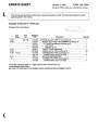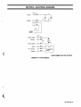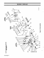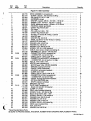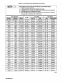
1
Millerfi
November 1994
Effective With
Form:
Style
OM-1580A
No. KE-5
OWNERS
MAN UA~L2~.
A1D-4RV
Read and follow these instructions and all
blocks carefully.
Give this manual to the operator.
safety
Have
cover
5194 8-134
761
and qualified persons
service this unit.
only trained
install, operate,
or
U
For
help,
MILLER Electric Mfg. Co., P.O. Box 1079,
WI 54912
414-734-9821
Call your distributor if you do not understand
or:
the directions.
Appleton,
'
1994 MILLER Electric
Mtg.
Co.
call your distributor
PRINTED IN USA
MILLERS
TRUE BLUETM LIMITED WARRANTY
(Equipment
This limited warranty
with
EffectIve January 1, 1995
serial number preface of KC
a
supersedes all previous MILLER
warranties snd is exclusive with
below, MILLER Electric
Subject
Mfg. Co., Appleton, Wisconsin, warrants to its original retail purcheser that new
MILLER equipment sold eher the effective date of this limited warranty is free of deI ecta in material and workmanship at the time it ia shipped by MILLER. Tills WAR
RANTY IS EXPRESSLY IN LIEU OF ALL OTHER WARRANTIES, EXPRESS OR
IMPLIED, INCLUDING THE WARRANTIES OF MERCHANTABILITY AND FITNESS.
*
to the terms end conditions
LIMITED WARRANTY
MILLER shall honor warranty claims
on
warranted
equipmenl
MILLERS
Original
2.
3 Years
or
warranties
expressed
True
BIueTM
Items furniahed
Limited Warranty shall not
by MILLER,
or
implied.
apply
to:
but manufactured
trade accessories. Theae items are covered
by others, such ax enginea or
by the manufacturers warranty, if
any.
2.
Consumable components; such as contact lips,
and relays or parts that fail due 10 normal wear.
3.
Equipment that
cutting nozzles,
has been modified
ment that has been
start on the dale that the
5 Years Parts 3
guarantees
contactors
listed below in the
warranty time periods. All warranty lime periods
equipment was delivered to the original retail purchaser, or
one year aher the equipment is sent to a North American distributor or eighteen
months aher the equipment is sent to an Intemational distributor,
event of such a failum within the
t.
other
Remote Controls
Accessory Kits
Replacement Parts
1.
Within the warranty periods listed below, MILLER will repair or replace any warmnted parta or components that fail due to such defects in material or workmanship.
MILLER must be notified in writing within thirty (30) days of such defecl or failure, at
which lime MILLER will provide instructiona on the warranty claim procedures to be
followed.
no
newer)
or
based upon
by any party other than MILLER,
improperly installed, improperfy operated or
or
equip
misused
equipment which has not had reasonable
and necessary maintenance, or equipment which has been used for operation
oulside of the specifications for the equipment.
industry standards,
or
Years Labor
MILLER PRODUCTS ARE INTENDED FOR PURCHASE AND USE BY COMMER
rectifiers
main power
CIAUINDUSTRIAL USERS AND PERSONS TRAINED AND EXPERIENCED IN
THE USE AND MAINTENANCE OF WELDING EOUIPMENT.
Parts and Labor
Transformer/Rectifier Power Sources
In the event of
Plasma Arc
Cutting
Power Sources
MILLER in
Robots
3.
2 years
Parts and Labor
Driven Wetding Generators
(NOTE; Engines are warranted separately by the engine manufacturer
a period of two years)
Engine
for
Air
Compressors
Year
4,
warranty claim covered by this warranty, the exclusive remedies
option; (t) repair; or (2j replacement; or, where authorized in
writing by
appropriate cases, (3) the reasonable cost of repair or replacement at an authorized MILLER service station; or (4) payment of or credit for the pur
chsse price (less reasonable depreciation based upon actual use) upon refum of the
goods at customers risk and expense. MILLERS option of repair or replacement
will be FOB., Factory at Appleton, Wisconsin, or FOB. at a MILLER authorized ser
vice facility us determined by MILLER. Therefore no compensation or reimbursement for transportation coats of any kind will be allowed.
a
shall be, at MILLERS
Semi-Automatic and Automatic Wire Feeders
TO THE EXTENT PERMItTED BY LAW, THE REMEDIES PROVIDED HEREIN
ARE THE SOLE AND EXCLUSIVE REMEDIES. IN NO EVENT SHALL MILLER BE
LIABLE FOR DIRECT, INDIRECT, SPECIAL, INCIDENTAL OR CONSEQUENTIAL
DAMAGES (INCLUDING LOSS OF PROFIT), WHETHER BASED ON CONTRACT, TORT OR ANY OTHER LEGAL THEORY.
Parts and Labor
Motor Driven Guns
Process Controllers
Water Coolant
Systems
HF Units
ANY EXPRESS WARRANTY NOT PROVIDED HEREIN AND ANY IMPLIED WARRANTY, GUARANTY OR REPRESENTATION AS TO PERFORMANCE, AND ANY
Grids
REMEDY FOR BREACH OF CONTRACT TORT OR ANY OTHER LEGAL
WHICH, BUT FOR THIS PROVISION, MIGHT ARISE BY IMPLICATION,
OPERATION OF LAW, CUSTOM OF TRADE OR COURSE OF DEALING. INCLUDING ANY IMPLIED WARRANTY OF MERCHANTABILITY OR FITNESS
FOR PARTICULAR PURPOSE, WITH RESPECT TO ANY AND ALL EQUIPMENT
FURNISHED BY MILLER IS EXCLUDED AND DISCLAIMED BY MILLER.
Spot Welders
THEORY
Load Bsnks
SDX Transformers
Running Gear/Trailers
Plasma Cuffing Torches (except APT, ZIPCUT
Field Options
& PLAZCUT
(NOTE Field options are covered under True BIueTM for
warranty period of the product they are installed in, or br
one year
5.
6 Months
6.
gO
Days
whichever
is
the
Models)
remaining
a minimum
greater.)
of
Some states in the U.S.A. do not allow limitations of how tong an implied warranty
lasts, or the exclusion of incidental, indirect, special or consequential damages, so
apply to you. This warranty provides apecit ic legal rights, and other rights may be available, but may vary from state to state.
I he above limitation or exclusion may not
Batteries
In Canada, legislation in some provinces provides for certain additional warranties
or remedies other than as stated herein, and to Ihe extent that they may not be
waived, the limitations and exclusions set out above may not apply. This Limited
Warranty provides specific legal rights, and other rights may be available, but may
Parts and Labor
MIG Guns/TIG Torches
APT, ZIPCUT & PLAZCUT Model Plasma Cutting Torches
~
from
province
to
province.
ii
RECEIVING-HANDLING
unpacking equipment, check carton for any damage that may have occurred during shipment. File any claims for loss or damage
delivering carrier. Assistance for filing or sett(ing claims may be obtained from distributor and/or equipment manufacturers
Transportation Department.
Before
with the
When
requesting
Use the
or
information about this
equipment, always provide Model Designation
and Serial
following spaces to record Model Designation and Serial or Style Number of your unit.
or
Style
Number,
The information is located
on
the
rating
label
nameplate.
Model
_________________________________________________________
Serial
or
Style
No,
_____________________________________________
Date of Purchase
________________________________________________
miller tt/g4
ERRATA SHEET
January 4,
FORM: OM-1580A
1995
Use above FORM number when
After this manual
appearing
was
printed,
extra manuals.
equipment design occurred. This sheet lists exceptions
to data
later in this manual.
CHANGES TO SECTION 9
Parts List
Change
refinements in
ordering
as
PARTS LIST
follows:
~
.
~
Dia.
**
Mkgs.
Part
No.
134 156
15-28
Replaced
With
...
15-29
172 995
172807
153491
153492
15-31
15-34
15-35
.
PLG3
*153493
153631
007826
134 858
15-37
134184
132611
15-
131 203
MOTOR, gear (Eff w/KE-51) (consisting of)
MOTOR, gear 1/Bhp 115V 2000RPM (consisting of)
KIT, brush replacement (consisting of)
CAP, brush
BRUSH, carbon
CIRCUIT CARD, digital tach
CABLE, port No. 18 3/c (order by ft)
CONNECTOR & PINS, (consisting of)
CONNECTOR, rect pin 20-l6ga
OPTICAL ENCODER DISC
CONNECTOR & PINS, (consisting
114656
**First
digit represents page no
Spare Parts.
Quantity
Description
digits following
CONNECTOR,
rect
dash represent item
1
1
1
2
2
1
2ff
1
6
1
of)
pin 24-lBga
no.
*Recommended
BE SURE TO PROVIDE STYLE NUMBER WHEN ORDERING REPLACEMENT PARTS.
1
3
EMF INFORMATION
Considerations About
Fields
N
Welding
And The Effects Of Low
Frequency
Electric And
Magnetic
____________________
The
To reduce
of the U.S.
procedures:
following is a quotation from the General Conclusions Section
Congress, Office of Technology Assessment, Biological
Effects of Power Frequency Electric & Magnetic Fields
Background Paper, OTA-BP-E-53 (Washington, DC: U.S.
Government Printing Office, May 1989): .
there is now a very
large volume of scientific findings based on experiments at the
.
magnetic
1.
Keep
2.
Arrange cables
3.
Do not coil
fields in the
cables close
workplace,
together by twisting
or
use
taping
to one side and away from the
the
following
them.
operator.
.
or
drape
cables around the
body.
cellular level and from studies with animals and
people which clearly
frequency magnetic fields can interact with, and
produce changes in, biological systems. While most of this work is
of very high quality, the results are complex. Current scientific
understanding does not yet allow us to interpret the evidence in a
single coherent framework. Even more frustrating, it does not yet
allow us to draw definite conclusions about questions of possible
flsk or to offer clear science-based advice on strategies to minimize
or avoid potential risks.
establish that low
Keep welding power
4.
source
and cables
as
far away
as
~ractical
Connect work clamp to workpiece
5.
as
close to the weld
as
possible.
About Pacemakers:
The above procedures are among those also normally
recommended for pacemaker wearers. Consult your doctor for
complete information.
modlo.1 4/93
TABLE OF CONTENTS
Section No.
SECTION 1
Page
SAFETY RULES FOR OPERATION OF ARC WELDING POWER SOURCE
1-1.
Introduction
1
1-2.
General Precautions
1
1-3.
Arc
4
1-4.
Standards Booklet Index
SECTION 2
No.
Welding
5
SAFETY PRECAUTIONS AND SIGNAL WORDS
2-1.
General Information And
2-2.
Safety
Alert
Symbol
And
Safety
Signal Words
6
6
SECTION 3SPECIFICATIONS
3-1.
Description
7
SECTION 4INSTALLATION
4-1.
Location
7
4-2.
Drive Motor
8
4-3.
Wire Guide And Drive Roll Installation For 4-Drive Roll Models
8
4-4.
Outlet Cable Connections
9
4-5.
Drive Motor Connections
9
SECTION 5
5-1.
SECTION 6
6-1.
6-2.
6-3.
SEQUENCE OF OPERATION
Welding
Wire
Threading
9
MAINTENANCE
Inspection And Upkeep
Cleaning Of Drive Rolls
Brush Inspection & Replacement
10
10
10
OM-1580A
-
11/94
Section No.
SECTION 7
7-1.
7-2.
SECTION 8
Page
TROUBLESHOOTING
General
Figure
11
Troubleshooting
Chart
11
ELECTRICAL DIAGRAMS
Diagram
SECTION 9
No.
8-1. Circuit
Diagram
13
PARTS LIST
9-1. Main
Assembly
14
LIST OF CHARTS AND TABLES
Table 7-1.
Troubleshooting
Table 9-1. Drive Roll And Wire Guide Kits
11
(4
Drive
Roll)
16
OM-1580A- 11/94
SECTION 1
SAFETY RULES FOR OPERATION OF ARC WELDING POWER SOURCE
INTRODUCTION
1.
welding
We learn by experience. Learning safety through per
sonal experience, like a child touching a hot stove is
harmful, wasteful, and unwise. Let the experience of oth
ers
teach you.
Safe practices developed from experience in the use of
welding and cutting are described in this manual. Re
development, and field experience have
evolved reliable equipment and safe installation, opera
tion, and servicing practices. Accidents occur when
equipment is improperly used or maintained. The rea
son for the safe practices may not always be given.
Some are based on common sense, others may require
search,
technical volumes to
explain. It is wiser
to follow the
rules.
cutting, (and chipping)
to
protect the eyes
Avoid
oily
or
greasy
clothing.
A
spark may ignite
Failure to observe these safe practices may cause seri
injury or death. When safety becomes a habit, the
ous
equipment
can
be used with confidence.
them.
Hot metal such as electrode stubs and workpieces
should never be handled without gloves.
Medical first aid and eye treatment. First aid facilities and
qualified first aid person should be available for each
shift unless medical facilities are close by for immediate
a
treatment of flash burns of the eyes and skin burns.
Ear
plugs should be worn when working on overhead or
in a confined space. A hard hat should be worn when
others work overhead.
Flammable hair preparations should not be used
Read and understand these safe practices before at
tempting to install, operate, or service the equipment.
Comply with these procedures as applicable to the par
ticular equipment used and their instruction manuals, for
personal safety and for the safety of others.
(L
or
from radiant energy and flying metal. Replace cover
glass when broken, pitted, or spattered. See 1 -3A.2.
sons
B.
intending
by per
to weld or cut.
Toxic Fume Prevention
Severe discomfort, illness or death can result from
fumes, vapors, heat, or oxygen enrichment or depletion
(orcutting) may produce. Prevent them with
ventilation
as described in ANSI Standard
adequate
Z49.1 listed in Standards index. NEVER ventilate with
that welding
oxygen.
These safe practices are divided into two Sections:
~eneral Precautions, common to arc welding and cut
~g: and 2-Arc Welding (and Cutting) (only).
Lead -,cadmium-, zinc-, mercury-, and beryllium-bear
ing and similar materials, when welded (or cut) may pro
duce harmful concentrations of toxic fumes. Adequate
Reference standards: Published Standards on safety
are also available for additional and more complete pro
cedures than those given in this manual. They are listed
in the Standards Index in this manual. ANSI Z49.1 is the
the area as well
most
complete.
The National Electrical Code, Occupational Safety and
Health Administration, local industrial codes, and local
inspection requirements also provide a basis for equip
ment installation, use, and service.
1-2.
GENERAL PRECAUTIONS
local exhaust ventilation must be used,or each person in
as the operator must wear an air-sup
plied respirator. For beryllium, both must be used.
Metals coated with orcontaining materials that emit toxic
fumes should not be heated unless coating is removed
from the work surface, the area is well ventilated and, if
necessary, while wearing an air-supplied respirator.
Work in
a
confined space
only while
and, if necessary, while wearing
an
it is being ventilated
air-supplied respira
tor.
Different arc welding processes, electrode alloys,
and fluxes can produce different fumes, gases, and
radiation levels. In addition to the information in this
Gas leaks in a confined space should be avoided.
Leaked gas in large quantities can change oxygen con
centration dangerously. Do not bring gas cylinders into a
confined space.
manual, be sure to consult flux and electrode manu
facturers Materiai Safety Data Sheets (MSDSs) for
to
specific technical data and precautionary measures
concerning their material.
A.
Burn Prevention
Wear protective clothing-gauntlet gloves designed for
use in welding, hat, and high safety-toe shoes. Button
shirt collar and pocket flaps, and wear cuff less trousers
qvoid entry of sparks and slag.
ar helmet with safety goggles and glasses with side
shields underneath, appropriate filter lenses or plates
(protected by clear cover glass). This is a MUST for
Leaving confined space,
shut OFF gas supply at source
prevent possible accumulation of gases in the space if
downstream valves have been accidentally opened or
left open. Check to be sure that the space is safe before
re-entering it.
Vapors from chlorinated solvents can be decomposed
by the heat of the arc (or flame) to form PHOSGENE, a
highly toxic gas, and other lung and eye irritating prod
ucts. The ultraviolet (radiant) energy of the arc can also
decompose trichioroethylene and perchloroethylene
vapors to form phosgene. DO NOT WELD or cut where
solvent vapors can be drawn into the welding or cutting
atmosphere or where the radiant energy can penetrate
OM-1580
Page
1
atmospheres containing even minute
trichioroethylene or perchioroethylene.
to
C.
amounts of
recommended in A6.O.
Waterfifling just
level may substitute for
inerting.
ment
explosion are: combustibles reached
by the arc, flame, flying sparks, hot slag or heated mate
rial; misuse of compressed gases and cylinders; and
Causes of fire and
(see preceding paragraph).
or sight to determine
smell
Hollow castings
welding
short circuits.
or
D.
To prevent fires and
Standard
explosion:
Keep equipment clean and operable, free of oil, grease,
(in electrical par(s) of metallic particles that can
and
short circuits.
If combustibles are in area, do NOT weld or cut. Move
the work if practicable, to an area free of combustibles.
Avoid
paint spray rooms, dip tanks, storage areas, venti
lators. If the work cannot be moved,
move
combustibles
at least 35 feet away out of reach of sparks and heat; or
protect against ignition with suitable and snug-fitting,
fire-resistant
Walls touching combustibles on opposite sides should
not be welded on (or cut). Walls, ceilings, and floor near
work should be protected by heat-resistant covers or
shields.
Fire watcher must be standing by with suitable fire extin
guishing equipment during and for some time afterweld
ing or cutting if:
appreciable combustibles (including building
construction) are within 35 feet
a.
b.
appreciable combustibles are further than 35
can be ignited by sparks
feet but
openings (concealed or visible) in floors orwalls
within 35 feet may expose combustibles to
c.
d.
Do NOT depend on
if it is safe to weld
of
cut.
containers must be vented before
cutting. They
can
explode.
Never weld or cut where the air
may contain flammable dust, gas,
as
sense
or
or
liquid vapors (such
gasoline).
Gas
Compressed
Equipment
precautions. Comply
with
precautions
in this
manual, and those detailed in CGA Standard P-i, SAFE
HANDLING OF COMPRESSED GASES IN CYLIN
DERS, listed ii in Standards Index.
i.
Pressure
Regulators
Regulator relief valve is designed to protect only the
regulator from overpressure; it is not intended to protect
any downstream equipment. Provide such protection
with
one or more
relief devices.
Never connect a regulator to a cylinder containing gas
other than that for which the regulator was designed.
shields.
covers or
or
Explosive atmospheres.
BE AWARE THAT flying sparks or failing slag can pass
through cracks, along pipes, throughwindows or doors,
and through wall or floor openings, out of sight of the
goggled operator. Sparks and slag can fly 35 feet.
cause
below
A container with unknown contents should be cleaned
Explosion Prevention
Fire and
as
working
Remove faulty regulatorfrom service immediately for re
pair (first close cylinder valve). The following symptoms
indicate a faulty regulator:
Leaks-if gas leaks externally.
Excessive Creep-if delivery pressure continues to rise
with downstream valve closed.
Faulty Gauge-if gauge pointer does not move off stop pin
when pressurized, nor returns to stop pin after pressure
release.
Repair.
Do NOT attempt to
repair. Send faulty regulators
for repair to manufacturers designated repair center,
where special techniques and tools are used by trained
personnel.
sparks
2.
combustibles adjacent to walls, ceilings, roofs,
or metal partitions can be ignited by radiant or
conducted heat.
Cylinders must be handled carefully to prevent leaks
and damage to their walls, valves, or safety devices:
Cylinders
Hot work
Avoid electrical circuit contact with cylinders
third rails, electrical wires, or welding circuits.
have been taken.
produce short circuit arcs that may lead to a serious acci
dent. (See i-3C.)
permit should be obtained before operation to
ensure supervisors approval that adequate precautions
After work is done, check that area is free of
glowing embers, and flames.
sparks,
An
empty container that held combustibles, or that can
produce flammable or toxic vapors when heated, must
be welded
cut, unless container has first
been cleaned as described in AWS Standard A6.O, listed
7 in Standards Index.
never
on or
This includes: a thorough steam or caustic cleaning (or a
solvent or water washing, depending on the combusti
bles solubility) followed by purging and inerting with ni
trogen or carbon dioxide, and using protective equipOM-1580
Page
2
ICC
or
DOT
assurance
including
They can
marking must be on each cylinder. It is an
safety when the cylinder is properly han
of
dled.
Identifying gas content. Use only cylinders with name of
gas marked on them; do not rely on color to identify gas
content. Notify supplier if unmarked. NEVER DEFACE
or alter name, number, or other markings on a cylinder, It
is illegal and hazardous.
Empties: Keep
mark MT;
promptly.
valves closed, replace caps securely;
keep them separate from FULLS and return
Prohibited
use.
Never use
a
cylinder
or
its contents for
other than its intended use, NEVER as a
roller.
support
or
outlet away from people and
with a clean lintless cloth.
sources
of
ignition. Wipe
Match
ocate or secure
cylinders
so
they
cannot be knocked
ver.
Passageways and work areas. Keep cylinders
where they may be struck.
clear of
regulator to cylinder. Before connecting, check
regulator label and cylinder marking area, and
that the regulator inlet and cylinder outlet match. N EVER
CONNECT a regulator designed for a particular gas or
gases to a cylinder containing any other gas.
that the
areas
Transporting cylinders. With a crane, use a secure sup
port such as a platform orcradle. Do NOT lift cylinders off
the ground by their valves or caps, or by chains, slings,
or
magnets.
Do NOT expose cylinders to excessive heat, sparks,
slag, and flame, etc. that may cause rupture. Do not al
low contents to exceed 130F.
where such exposure exists.
Protect
Cool with water spray
cylinders particularly valves
from
bumps, falls,
falling objects, and weather. Replace caps securely
when moving cylinders.
Stuck valve. Do NOT use a hammer or wrench to open a
cylinder valve that can not be opened by hand. Notify
your
supplier.
Mixing
gases. Never try to mix any gases in
Never refill any
a
cylinder.
cylinder.
Cylinderfittings should never be modified or exchanged.
Tighten
connections. When
retighten using properly fitting
Use ferrules or clamps designed for the hose (not ordi
nary wire or other substitute) as a binding to connect
hoses to fittings.
No copper
tings
to
tubing splices. Use only standard brass fit
splice hose.
Avoid
long runs to prevent kinks and abuse. Suspend
hose off ground to keep it from being run over, stepped
on, or otherwise damaged.
Coil excess hose to prevent kinks and
sparks, slag,
5.
Pressurizing Steps:
Drain regulator of residual gas through suitable vent be
fore opening cylinder (or manifold valve) by turning ad
justing screw in (clockwise). Draining prevents exces
sive compression heat at high pressure seat by allowing
seat to open on pressurization. Leave adjusting screw
engaged slightly on single-stage regulators.
and
Open cylinder valve slowly so that regulator pressure in
slowly. When gauge is pressurized (gauge
reaches regulator maximum) leave cylinder valve in fol
lowing position: For oxygen, and inert gases, open fully
to seal stem against possible leak. For fuel gas, open to
less than one turn to permit quick emergency shutoff.
creases
Use pressure charts (available from your supplier) for
safe and efficient, recommended pressure settings on
regulators.
Check for leaks on first pressurization and regularly
there-after. Brush with soap solution (capfull of Ivory Liq
uid* or equivalent per gallon of water). Bubbles indicate
leak. Clean off soapy water after test; dried soap is com
bustible.
and open flame.
area out
and
splic
ResponsibIlities
Remove leaky or defective equipment from service im
mediately for repair. See User Responsibility statement
in equipment manual.
F.
cylinder valve outlet of impurities that may clog
orifices and damage seats before connecting regulator.
Except for hydrogen, crack valve momentarily, pointing
Leaving EquIpment Unattended
Close gas
G.
Proper Connections
lean
User
by
Examine hose regularly for leaks, wear, and loose con
nections. Immerse pressured hose in water; bubbles indicate leaks.
4.
regulator while opening cylinder valve.
tangles.
damage by sharp edges,
Repair leaky or worn hose by cutting
ing (1-2D3). Do NOT tape.
wrench.
Regulator outlet (or hose) connections may be identified
by right hand threads for oxygen and left hand threads
(with grooved hex on nut or shank) for fuel gas.
E.
Protect hose from
con
LEFT HAND threads.
Stand to side of
gases.
threaded
Adapters. Use a CGA adapter (available from your sup
plier) between cylinder and regulator, if one is required.
use two wrenches to tighten adapter marked RIGHT and
Hose
rohibited use. Never use hose other than that designed
for the specified gas. A general hose identification rule
is: red forfuel gas, green for oxygen, and black for inert
assembling
nections, clean and smooth seats where necessary.
Tighten. If connection leaks, disassemble, clean, and
supply
at source and drain gas.
Rope Staging-Support
Rope staging-support should not be
cutting operation; rope may burn.
used for welding
or
OM-1580
3
*Trademark of Proctor & Gamble.
Page
Viewing
ARC WELDING
1-3.
Comply with precautions in 1-1, 1-2, and this section.
Arc Welding, properly done, is a safe process, but a
careless operator invites trouble. The equipment carries
high currents at significant voltages. The arc is very
bright and hot. Sparks fly, fumes rise, ultraviolet and in
frared energy radiates, weidments are hot, and com
pressed gases may be used. The wise operator avoids
unnecessary risks and protects himself and others from
accidents. Precautions are described here and in stan
Others working in
flash goggles.
area.
See that a~l persons
Before starting to weld, make
bay doors are closed.
sure
wearing
are
that screen
flaps
or
Toxic Fume Prevention
B.
Comply with precautions
in 1 -2B.
Generator engine exhaust must be vented to the outside
air. Carbon monoxide can kill.
dards referenced in index.
A.
the weld. Provide face shields for all persons
looking directly at the weld.
who will be
Burn Protection
FIre and
C.
Comply with precautions
Comply with precautions
bright. Its radiation
can damage eyes, penetrate lightweight clothing, reflect
from light-colored surfaces, and burn the skin and eyes.
Equipments
equipment.
Skin burns resemble acute sunburn, those from gasshielded arcs are more severe and painful. DONT GET
BURNED; COMPLY WITH PRECAUTIONS.
cause a
The welding arc is intense and visibly
Protective
1.
Clothing
Wear long-sleeve clothing (particularly for gas-shielded
arc) in addition to gloves, hat, and shoes (1 -2A). As nec
essary, use additional protective clothing such as
leatherjacket orsleeves,flame-proof apron, and fire-re
sistant leggings. Avoid outer garments of untreated cot
ton.
Bare skin protection. Wear dark, substantial clothing.
Button collar to protect chest and neck and button pock
ets to
2.
Prevention
in 1 -2C.
rated capacity. Do not overload arc welding
It may overheat cables and cause a fire.
Loose cable connections may overheat or flash and
fire.
Never strike an arc on a cylinder or other pressure ves
sel. It creates a brittle area that can cause a violent rup
ture or lead to such a rupture under rough handling.
Compressed Gas Equipment
D.
Comply with precautions
in 1 -2D.
Shock Prevention
E.
Exposed hot conductors or other bare metal in the weld
ing circuit, or in ungrounded, electrically-HOT equip
ment can fatally shock a person whose body becomes a
conductor. DO NOT STAND, SIT~ LIE, LEAN ON, OR
TOUCH a wet surface when welding, without suitable
prevent entry of sparks.
Eye
Explosion
in 1-2.
and Head Protection
protection.
Protect eyes from exposure to
electric arc without protection.
arc.
NEVER look at
an
To protect
against shock:
Wear
Welding
helmet or shield containing a filter plate shade
no. 12 or denser must be used when welding. Place over
face before striking arc.
Protect filter
plate with
Cracked
broken helmet
or
a
worn; radiation can pass
clear
or
cover
plate.
shield should NOT be
to cause burns.
through
Cracked, broken, or loose filter plates must be replaced
IMMEDIATELY. Replace clear cover plate when broken,
pitted, or spattered.
Flash goggles with side shields MUST be worn under
the helmet to give some protection to the eyes should the
helmet not be lowered over the face before an arc is
struck. Looking at an arc momentarily with unprotected
eyes
(particularly a high intensity gas-shielded arc)
retinal burn that may leave
in the field of vision.
cause a
area
3.
Protection of
a
can
permanent dark
Nearby Personnel
Enclosed welding area. For production welding, a sepa
rate room or enclosed bay is best. In open areas, sur
round the operation with low-reflective, non-combusti
ble screens or panels. Allow for free air circulation, par
ticularly at floor level.
OM-1580
Page 4
dry insulating gloves and body protection. Keep
body and clothing dry. Never work in damp area without
adequate insulation against electrical shock. Stay on a
dry duckboard, or rubber mat when dampness or sweat
can not be avoided. Sweat, sea water, or moisture be
tween body and an electrically HOT part or grounded
metal reduces the electrical resistance, and could en
dangerous and possibly lethal currents to flow
through the body.
able
A
voltage will exist between the electrode and any con
ducting object in the work circuit. Examples of conduct
ing objects include, but are not limited to, buildings, elec
trical tools, work benches, welding power source cases,
workpieces, etc. Never touch the electrode and any
metal object unless the welding power source Is off.
1.
Grounding
the
Equipment
Arc welding equipment must be grounded according to
the National Electrical Code, and the work must be
grounded according
And
to ANSI Z49.1
Safety
in
Welding
Cutting.
When
installing, connect the frames of each unit such as
welding power source, control, work table, and water cir
culatorto the building ground. Conductors must be ade
quate to carry ground currents safely. Equipment made
electrically HOT by stray current may shock, possiblyfa
tally. Do NOT GROUND to electrical conduit, orto a pipe
carrying ANY gas or flammable liquid such as oil or fuel.
hree-phase connection. Check phase requirements of
uipment before installing. If only 3-phase power is
vailable, connect single-phase equipment to only two
wires of the 3-phase line. Do NOT connect the equip
ment ground lead to the third (live) wire, or the equip
ment will become electrically HOT-a dangerous condi
tion that can shock, possibly fatally.
Before welding, check ground for continuity. Be sure
conductors are touching bare metal of equipment
frames at connections.
If a line cord with a ground lead is provided with the
equipment for connection to a switchbox, connect the
ground lead lathe grounded switchbox. If a three-prong
plug is added for connection to a grounded mating re
ceptacle, the ground lead must be connected to the
ground prong only. If the line cord comes with a threeprong plug, connect to a grounded mating receptacle.
Never remove the ground prong from a plug, or use a
plug with a broken off ground prong.
2.
Welding power sources used with shielded
metal arc welding (SMAW) and similar proc
esses may not be equipped with welding power
output on-oft control devices. With such equip
ment the electrode is electrically HOT when the
power switch is turned ON. Never touch the
electrode unless the welding power source is
off.
7.
Safety
Devices
Safety devices such as interlocks and circuit breakers
should not be disconnected or shunted out.
Before installation,
inspection, or service, of equipment,
remove line fuses (or lock or redtag switches) to prevent accidental turning ON of power.
Disconnect all cables from welding power source, and
pull all 115 volts line-cord plugs.
shut OFF all power and
Do not open power circuit or change polarity while weld
ing. If, in an emergency, it must be disconnected, guard
against shock burns, or flash from switch arcing.
Leaving equipment
unattended.
Always
shut OFF and
disconnect all power to equipment.
Power disconnect switch must be available
Electrode Holders
near
the
welding power source.
Fully insulated
NOT
3.
use
electrode holders should be used. Do
holders with protn.iding screws.
F.
Protection For Wearers of Electronic Life
Sup
port Devices (Pacemakers)
Connectors
Fully insulated lock-type connectors
~n welding cable lengths.
should be used to
Cables
Magnetic fields from high currents can affect pacemaker
operation. Persons wearing electronic life support
equipment (pacemaker) should consult with their doctor
before going near arc welding, gouging, or spot welding
operations.
Frequently inspect cables forwear, cracks and damage.
IMMEDIATELY REPLACE those with excessively worn
or damaged insulation to avoid possibly-lethal shock
from bared cable. Cables with damaged areas may be
For more information, ref erto the
their latest revisions and comply
taped
1.
ANSI Standard Z49.1, SAFETY IN WELDING AND
CUTTING obtainable from the American Welding
Society, 550 N.W. LeJeune Ad, Miami, FL 33126.
2.
NIOSH, SAFETY AND HEALTH IN ARC WELDING
AND GAS WELDING AND CUTI1NG obtainable
from the Superintendent of Documents, U.S. Gov
give
to
resistance
equivalent
to
original
Keep
dry, free of oil and grease, and
from hot metal and sparks.
cable
5.
cable.
1-4.
protected
Terminals And Other Exposed Parts
Terminals and other exposed parts of electrical units
should have insulating covers secured before operation.
6.
Electrode
a.
Equipment with output on/off control
ernment
Equipment
contactor)
without output on/oft control
(no
20402.
4.
ANSI Standard Z87.1, SAFE PRACTICES FOR
OCCUPATION AND EDUCATIONAL EYE AND
FACE PROTECTION obtainable from the American
National Standards Institute, 1430 Broadway, New
York, NY 10018.
5.
ANSI Standard Z41.1, STANDARD FOR MENS
SAFETY-TOE FOOTWEAR obtainable from the
American National Standards Institute, 1430 Broad
way, New York, NY 10018.
6.
ANSI Standard Z49.2, FIRE PREVENTION IN THE
USE OF CUTTING AND WELDING PROCESSES
mally are equipped with devices that permit on
off control of the welding power output. When so
b.
Printing Office, Washington, D.C.
OSHA, SAFETY AND HEALTH STANDARDS,
29CFR 1910, obtainable from the Superintendent of
Documents, U.S. Government Printing Office,
Washington, D.C. 20402.
Welding
equipped the electrode wire becomes electri
cally HOT when the power source switch is ON
and the welding gun switch is closed. Never
touch the electrode wire or any conducting ob
ject in contact with the electrode circuit unless
the welding power source is off.
following standards or
as applicable:
3.
(contactor)
power sources for use with the gas
metal arc welding (GMAW), gas tungsten arc
welding (GTAW) and similar processes nor
STANDARDS BOOKLET INDEX
OM-1 580
Page
5
7.
obtainable from the American National Standards
Institute, 1430 Broadway, New York, NY 10018.
fromthe Compressed Gas Association, 1235 Jeffer
son Davis Highway, Suite 501, Arlington, VA 22202.
AWS Standard A6.0, WELDING AND CUTTING
CONTAINERS WHICH HAVE HELD COMBUS
TIBLES obtainable from the American Welding So
ciety, 550 N.W. LeJeune Rd, Miami, FL 33126.
12. CSA Standard W117.2, CODE FOR SAFETY IN
WELDING AND CUTTING obtainable from the Ca
nadian Standards Association, Standards Sales,
178 Rexdale Boulevard, Rexdale, Ontario, Canada
M9W1R3.
8.
NFPA Standard 51, OXYGEN-FUEL GAS SYS
TEMS FOR WELDING, CUTTING, AND ALLIED
PROCESSES obtainable from the National Fire
Protection Association,
13. NWSA
Batterymarch Park, Quincy,
19103.
Standard 70, NATIONAL ELECTRICAL
CODE obtainable from the National Fire Protection
Association, Batterymarch Park, Quincy, MA
NFPA
Welding Society Standard AWSF4.1,
RECOMMENDED SAFE PRACTICES FOR THE
PREPARATION FOR WELDING AND CUTTING
OF CONTAINERS AND PIPING THAT HAVE HELD
HAZARDOUS SUBSTANCES, obtainable from the
American Welding Society, 550 N.W. LeJeune Rd.
14. American
02269.
10. NFPA Standard 51B, CUTTING AND WELDING
PROCESSES obtainable from the National Fire
Protection Association,
MA 02269.
11. CGA
Welding Supply
Association, 1900 Arch Street, Philadelphia, PA
MA 02269.
9.
booklet, WELDING SAFETY BIBLIOGRA
PHY obtainable from the National
Batterymarch Park, Quincy,
Pamphlet P-i, SAFE HANDLING OF COM
PRESSED GASES
IN
CYLINDERS obtainable
Miami, FL 33126.
15. ANSI Standard Z88.2, PRACTICE FOR RESPIRA
TORY PROTECTION, obtainable from the Ameri
can National Standards Institute, 1430 Broadway,
New York, NY 10018.
SECTION 2- SAFETY PRECAUTIONS AND SIGNAL WORDS
2-1.
A.
GENERAL INFORMATION AND SAFETY
General
Information
presented in this manual and on various la
plates on the unit pertains to equipment
installation,
design,
operation, maintenance, and
troubleshooting which should be read, understood, and
followed for the safe and effective use of this equipment.
bels, tags, and
2-2. SAFETY
WORDS
B.
Safety
The installation, operation, maintenance, and trouble
shooting of arc welding equipment requires practices
and procedures which ensure personal safety and the
safety of others. Therefore, this equipment is to be in
stalled, operated, and maintained only by qualified per
sons in accordance with this manual and all applicable
codes such as, but not limited to, those listed at the end
of Section 1
Safety Rules For Operation Of Arc Weld
ing Power Source.
OM-1580
Page
6
SYMBOL
AND
SIGNAL
The
following safety alert symbol and signal words are
used throughout this manual to call attention to and iden
tify different levels of hazard and special instructions.
AA
This safety alert symbol is used with the signal
words WARNING and CAUTION to call atten
tion to the safety statements.
a
WARNING statements identify procedures or
practices which must be followed to avoid seri
ous personal injury or loss of life.
a
CAUTION statements identify procedures or
practices which must be followed to avoid minor
personal injury or damage to this equipment.
The
nameplate of this unit uses international symbols for
labeling the front panel controls. The symbols also ap
pear at the appropriate section in the text.
ALERT
IMPORTANT statements identify special instructions
necessary for the most efficient operation of this equip
ment.
SECTION 3
SPECIFICATIONS
Table 3-1.
Speed Range
Per Minute
Specifications
Electrode Wire
Diameter Capacity
Dimensions
Height
.030 thru 1/8 in.
50 to 780 in.
(1.3
3-1.
to 1
9.8m)
(0.8
thru
3.2mm)
DESCRIPTION
with the MRV-6
arc
assembly is designed for use
welding robot. This is a four drive roll
SECTION 4
(225 mm)
(324 mm)
3/8 in. (238mm)
Width 123/4 in.
9
Length
unit with
The Al D-4RV wire drive
Weight
8 7/8 in.
a
mounting
18 lbs
(7.85 kg)
bracket. The drive
assembly is fac
tory installed onto the robot arm and functions as an inte
gral part of the robot welding system.
INSTALLATION
3.54 In.
(90 mm)
-~
12-3/4
~
~-
I
I
8.27 In.
(218 mm)
~
-
~-
9.3/8 In.
ST.134 761
Figure
4-1.
LOCATION
4-1. Overall Dimensions And
(Figure 4-1)
efficiency of this unit and associated
reduced when they are subjected to
The service life and
components
high
are
levels of dust, dirt, moisture, corrosive vapors, and
Mounting
Hole
Layout
extreme heat.
The drive
4-1
Figure
layouts.
assembly is factory installed onto the robot.
gives overall dimensions and mounting hole
OM-1 580
Page
7
DRIVE MOTOR
4-2.
a
ment of the
housing up or down in relation to the motor
adjustment has been factory set, but if
becomes
readjustment
necessary, loosen mount ing
drive gears. This
CAUTION: LOSS OF GEAR OIL OR DIRT EN
TERING GEAR CASE WILL DAMAGE MO
TOR.
bolts, weld terminal nuts and bolts. Slide the wire drive
The gear case of the drive motor is equipped
with two vent screws. Do not remove or discard
the vent screws before operation.
housing upward or downward until the gears on th
housing have a slight amount of clearance (backlash
from the motor gear. Tighten mounting bolts, weld termi
nal bolts and nuts.
WIRE GUIDE AND DRIVE ROLL INSTALLA
4-3.
IMPORTANT:
TION FOR 4-DRIVE ROLL MODELS
Proper clearance between the steel
important. The proper clearance is 0.003 inch
(0.076 mm). This is approximately the same thickness
as a sheet of standard writing paper. The easiest way to
obtain the proper alignment is to insert a piece of 0.003
in. (0.076mm) thick standard writing paper between the
motor and drive roll, and then tighten down the drive roll
assembly. If This proper clearance is not maintained in
the in the gears, they may wear severely, bind, cause er
gears is
Upon
initial installation,
or as a
result of
changes in wire
required wire
size and type, it is necessary to install the
guides and drive rolls. Select drive rolls
according
to
Table 9-1.
After
obtaining
rolls, proceed
A.
the appropriate wire
follows:
guides
Wire Guide Installation
(Figure 4-2)
Loosen the inlet and intermediate wire
1.
ing
and drive
as
ratic wire
B.
Wire guides should be installed so that
tip(s) of the guide is as close to the drive roll as
possible without touching. Recheck wire guides after
drive rolls are installed, and adjust if necessaly.
the
Figure
4-2. Secure
guides as illus
by tightening securing
Drive Roll Installation
Loosen pressure adjustment knobs and
free of the covers.
2.
Pivot gear
3.
with the drive roll gears, rotate the motor gear securing
bolt therebymoving the gearin or out to the desired posi
Cog
The wire drive
housing
is made with
adjust-
covers
Loosen and
4.
mounting holes of sufficient clearance to provide
4-2 and
1.
IMPORTANT: The alignment of the motor drive gear
with the drive roll gears has been factory set, but if read
justment becomes necessary, proceed as follows: Be
hind the motor drive gear (see Figure 4-2) is a spring
washer(s). To obtain proper alignment of the motor gear
tion.
(Figure
4-3)
feed the wire.
screws.
IMPORTANT:
break.
IMPORTANT: When the grooves become worn, reverse
each drive roll, locating the unused groove in position to
Install inlet and intermediate wire
trated in
or
guide secur
screws.
IMPORTANT:
2.
feed,
pivot
them
away to expose pressure gears.
remove
the three
securing
screws on
each gear.
drive roll onto each drive gear and pressure
and secure with screws.
Slide
a
gear,
align holes,
IMPORTANT:
To ensure proper gripping action of Udrive rolls, both rolls should be installed showing
slots on the side or both should show the side without
slots. Also, it is necessary to line up the blunted teeth on
the pressure gear roll directly over the spaces between
the teeth on the drive roll (see Figure 4-3).
Inlet Wire Guide
And Securing Screw
Outlet Cable
Connector
Securing Screw
ST.070 ~
Figure
OM-1560
PageS
4-2. Wire Guide And Drive Roll Installation
4-4.
1.
OUTLET CABLE CONNECTIONS
Loosen the outlet cable connector
(Figure 4-2)
securing
knob.
Pressure Drive Rolls
(Slotted Side)
IMPORTANT: Wire guides should be installed so that
the tip of the guide is as close to the drive roll as possible
without touching.
2.
Insert the outlet cable connector, which includes the
installed outlet guide, into the drive assembly oppo
site the inlet
the outlet cable connector
3.
Tighten
4.
Connect the 4-pin
4-socket receptacle
4-3.
knob.
from outlet cable to the
the motor
mounting
bracket.
ST-045 282-C
Make connections
Figure
plug
on
securing
DRIVE MOTOR CONNECTIONS
4-5.
Drive Rolls
Side Shown)
(Slotted
guide.
U-Cog
Drive Roll Installation
according to instructions in the
lation section of robot Owners
instal
Manual.
SECTION 5- SEQUENCE OF OPERATION
5-1.
WELDING WIRE THREADING
WARNING:
WELDING
wounds.
ELECTRIC
WIRE
can
4.
kill.
SHOCK
can
cause
puncture
faces to
5.
Do not touch live electrical parts.
Cut off any portion of the free end of the wire which is
not straight. If necessary, straighten wire to remove
cast. Be sure that the cut end is free from rough sur
and
ly
when
threading welding
6.
7.
2.
Install the wire (reel-type or spool-type)
structed in the robot Owners Manual.
3.
knob(s) on the drive roll pressure adjust
ment(s), pivot the pressure adjustment(s) free of the
cover(s), and pivot the pressure gear assembly(ies)
away to an open position.
assembly.
as
in
IMPORTANT: Spooled wire has a tendency to unravel
when loosened from the spool. Maintain a firm grip on
threading operation.
closed mak
Pivot the pressure adjustment knob(s) until the
washer(s) on the pressure adjustment(s) is seated
on
8.
top of the cover(s).
Turn the pressure adjustment knob(s) in clockwise
direction until the drive rolls are tight against the
welding
Loosen the
the
assembly(ies)
sure
also be in the grooves of the drive rolls.
in contact with it are
Connect the gun to the drive motor
during
Pivot the pressure gear
the teeth on the pressure gear mesh with
the teeth on the drive gear. The welding wire must
1.
the wire
on
4 in.
ing
wire.
welding wire and all metal parts
energized while welding.
The
through the inlet wire guide (and inter
guide, if applicable), past the drive rolls,
into the outlet wire guide. Feed approximate
(102 mm) of wire into the outlet wire guide.
Feed the wire
mediate
Do not energize welding power source and
robot control until instructed to do so.
Do not point gun toward any part of the body,
any conductive surface, or other personnel
permit proper feeding.
wire. Do not
overtighten. Further adjust
clamping pressure can be
welding power source and the weld
ment to attain desired
made after the
control are put into operation.
9.
Energize
the
welding
power
IMPORTANT: See robot Owners
source.
Manual for wire inch
ing procedures.
OM-1580
Page
9
SECTION 6- MAINTENANCE
IMPORTANT:
Even, six months inspect the labels on
legibility. All precautionary labels must be
maintained in a clearly readable state and replaced
ihis unit for
IMPORTANT: Failure to properly maintain the drive roll
can result in a buildup of wire particles which will de
crease the efficiency of the wire feeding operation.
when necessary See Parts List for part number of pre
cautionary labels.
6-3.
BRUSH
INSPECTION
6-1 and 6-2)
REPLACEMENT
&
(Figures
WARNING:
ELECTRIC SHOCK can kill;
MOVING PARTS can cause injury; WELDING
WIRE can cause puncture wounds; HOT
SURFACES can burn skin.
a
Do not touch live electrical parts.
Disconnect input power to the drive motorand
shut down the welding power source and robot
before inspecting or servicing.
Allow
6-1.
components
to cool before
servicing.
The brushes should be
ing
a
WARNING: Read and follow safety informa
tion at beginning of entire Section 6-1 before
proceeding.
Shut down unit and associated
2.
Open brush cap by sliding screwdriver
and lifting. Remove brush cap.
3.
Grasp spring retaining
Make
sure
welding
power
source
and robot is shut
4.
long-nose pli
Push spring retaining bracket in slightly and move
towards brush. This should release the spring asand it
can
be removed.
gun and outlet cable for broken areas,
cracks and loose parts; tighten, repair, and replace
Spring
required.
Brush
3.
any weld spatter or foreign matter
which may accumulate around the nozzle orifice.
Use a hardwood stick, never a metal tool.
4.
Repair or replace, as required, all hose and cable;
give particular attention to frayed and cracked insu
lation and areas where it enters equipment.
Carefully
remove
grime from components; mois
parts and cable.
)
rv(~4I
Remove grease and
ture from electrical
Blow out the gun wire guide liner with compressed
changing wire. This will remove any metal
and
dirt that may have accumulated.
chips
Spring Retainining
Figure
air when
6-2.
bracket with
Inspect
as
6.
under catch
ers.
sembly
5.
equipment.
INSPECTION AND UPKEEP
down.
2.
inspected periodically depend
usage and conditions.
1.
Usage and shop conditions will determine the frequency
and type of maintenance. Inspect equipment as follows:
1.
on
Bracket
6-1. View Of
Brush
Pigtail
Spring Assembly And
Cap Is Opened
S0088
Brush
When Brush
CLEANING OF DRIVE ROLLS
Long-Nose
Pliers
it will become necessary to clean the wire
the drive rolls. This cleaning operation can be
Occasionally
groove
on
performed
a
with
a
wire brush.
WARNING: Read and follow safety informa
tion at beginning of entire Section 6-1 before
proceeding.
To clean the wire grooves, disconnect input power from
unit before removing the drive roll(s) and see Sections
3-3 and 3-4 for removal and installation instructions.
a
WARNING:
cause
HIGH ROTATIONAL SPEED may
to drive rolls and injure per
damage
sonnel.
Do not allow drive rolls to rotate at high speed
if compressed air is used for cleaning the drive
roll assembly.
OM-1 580
Page
10
IMPORTANT: Spring
assembly hooks here.
Figure
6-2. View Of
S-oo8g
Spring Assembly
And Brush
From Armature End Of Motor
Pull brush out
5.
using
brush
10.
pigtail.
Using long-nose pliers, insert spring assembly be
sliding the spring retaining bracket along
the brush box wall. The spring retaining bracket
hooks on the brush box wall as illustrated in Figure
side brush
6.
If
is necessary (brushes are less than
6.4mm in length) disconnect the brush pig
replacement
1/4 in.
or
tail from the brush box tab and
7.. Connect
new
brush
pigtail
remove
brush.
6-2.
11. If the
spring retaining bracket is in place, it will
against the brush box wall when the pliers are
to brush box tab.
pigtail through slot in brush box. Ensure that
the pigtail will not come into contact with a metal sur
8.
leased.
Route
12. Ensure that the
face.
lustrated in
Insert brush into brush box. Ensure that the low end
9.
of the bevel
on
the
top of the brush is towards the
spring.
be
re
13.
Replace
spring is in the proper position
Figures 6-1 and 6-2.
as
il
and latch the brush cap.
14. Reconnect power to all
eration.
equipment
and
resume
op
SECTION 7- TROUBLESHOOTING
IMPORTANT:
Troubleshooting
this unit for
sons.
maintained
Every six months inspect the labels on
legibility. All precautionary labels must be
in a clearly readable state and replaced
when necessary. See Parts List for part number of pre
cautionary labels.
7-1.
The
following
remedies for
to be
chart is
some
performed only
be
qualified
per
designed to diagnose and provide
develop in
of the troubles that may
this unit.
Use this chart in
GENERAL
conjunction with the instructions in this
performing troubleshooting procedures. If
the trouble is not remedied after performing these pro
cedures, the nearest Factory Authorized Service Sta
tion should be contacted. In all cases of equipment mal
manual while
It is assumed that proper installation has been made,
to Section 4 of this manual, and that the unit
according
has been
7-2.
functioning properly
until trouble
developed.
function, the manufacturers
TROUBLESHOOTING CHART
a
WARNING:
be
ELECTRIC SHOCK
can
a
kill.
Do not touch live electrical parts.
Shut down unit, welding power source, and
robot, and disconnect input power employing
locko ut/tagging procedures before
Lockout/tagging procedures
disconnecting
Limit drive motor
repairs
to brush
replace
ment.
are very strong. If disassembly is at
tempted, injury to fingers and hands may result from a
magnet being drawn back into the motor. The field mag
nets are matched sets and operation may be affected if
the magnets are tampered with. Warranty is void if the
motor is tampered with.
The field magnets
consist of
padlocking
line
disconnect switch in open position, removing fuses from
fuse box, or shutting off and red-tagging circuit breaker
other
DISASSEMBLY OF MOTOR
CAUTION:
FIELD MAGNETS can result In personal Inju
ry and equipment damage.
inspecting or
seivicing.
or
recommendations should
strictly followed.
device.
OM-1 580
Page
11
Table 7-1.
TROUBLE
Wire Feeds
Troubleshooting
REMEDY
PROBABLE CAUSE
erratically.
Obstruction in gun contact tube.
Clear obstruction.
Drive motor
Secure
plug
not secure to cord
plug
connection.
plug.
Incorrect pressure
on
drive rolls.
~
Rotate pressure adjustment knob(s)
clockwise in 1/4 turn increments until
wire slippage stops. If excess pres
sure is required, check outlet cable
and gun contact tube for obstruc
tions.
Drive roll is too
ing used.
large for wire
size be-
Change to proper size drive
Sections 4-3).
Worn drive roll.
Replace drive
Dirt in drive roll.
Clean drive roll
tion 6-2.
Incorrect hub tension.
Readjust
Owners
Wire stops
feeding
while
welding.
Drive rolls
misaligned.
Operations Module servo light on,
Program Module display on, motor
servo light(s) off.
Page
12
servo
light(s).
Check
light(s)
Loose
OM-1 580
Replace
Burned out motor
servo
light
connection
(see Sections 4-3).
as
instructed in Sec
hub tension
Manual.
drive rolls
Realign
Motor.
roll
roll (see
(see
robot
(see Section 4-3).
motor.
and replace motor
PL1 and/or PL2.
servo
Secure servo light connection (see
robot Owners Manual.
SECTION 8- ELECTRICAL DIAGRAMS
PLG2
5-
.
+24VDC
I
1+
1+
C))
PL
COMMON
2
<
(2)
PL
CRN
6
3
4
SHOCK
SENSOR
PLG3
MOTOR POWER
~
<
.4HT
~+CW
2~BOARD
&cw
CHASSIS
MOTOR POWER
i-h
5<
MI
8LK
BLK
+5VDC
TACH
SIGNAL
COMMON
6
TACHOMETER
Circuit
Diagram 8-1.
Circuit
Diagram
No. SA-1 34 193-A
Diagram
OM.1580
Page
13
C/) m C, -l 0 z (0
-IU) I- U) -I
750-A
ST-134
36
37
38
)
36-38
Includes Items
40
28
Asembly
26
Includes Item
Main
13
21
9-1.
14
Figure
42
3
15
16
14
42
Kits
Guide 9-1
Wire
&
Includes
13-16
Items
43
I
44
Table
45
Roll See
Drive
I
52
For
0
7
0
51 50 49 48 47 46
Item
No.
Dia.
Mkgs.
Part
No.
Description
Figure
1
046 779
602 154
010 224
2
3
4
085
085
010
085
Assembly
DRIVE ASSEMBLY, (consisting of)
SCREW, .250-20 x .500 hexwhd sti
PIN, spring CS .187 x 1.000
1
slffmg
.
2
2
.
242
FASTENER, pinned
WASHER, cupped .328 ID x .812 OD x .125 lip stl
SPRING, cprsn .770 OD x .105 wire x 1.225 Ig
KNOB, adjustment tension 1 .25Odia x .312-18 thrd
HOUSING, adapter gun/feeder
LEVER, mtg pressure gear
2
2
2
5
6
7
8
9
10
11
12
244
231
243
166 337
166 071
079634
151828
166 338
13
144 172
14
15
166072
604538
16
079 772
17
134177
INSULATOR,driveassy
1
18
075 150
010910
602 213
079 624
WASHER, shldr .406 ID nyl
WASHER, fIat .406 ID stl
WASHER, lock .380 ID stl split
SCREW, .375-16 x 2.250 hexhd sti
CABLE, shock sensor & lights (consisting of)
GROMMET, rbr .375 ID x .500 mtg hole
1
1
19
20
21
22
23
24
134 171
PLG2
25
26
PLG1
27
28
29
30
31
32
33
34
35
PLG3
36
37
38
39
40
41
42
43
44
45
46
47
48
49
~-
9-1. Main
Quantity
50
51
52
PL1 ,2
010 116
134 860
134 184
604 571
048 282
079 534
092 865
134 156
080 802
049 033
134 157
049 029
049 032
007 826
134 858
134 184
049 030
110 733
049 031
134 176
117 160
*115 276
010142
053 842
079 626
605 518
044 735
602 207
602241
072 010
000 418
093 664
601872
602 243
.
.
.
2
1
1
.PIN,hinge
1
.PIN,cotterhair.042x.750
LEVER, mtg pressure gear
FITTING, brs barbed M 3/l6tbg
1
1
.
.
x
.250-20
1
.SPACER,gear
WASHER,
.
.
.
.
.
1
1
flat .344 ID stl
KNOB, T 2.000 bar w/.312-18 stud
CONNECTOR & PINS,
x
1.500
Ig
1
2
1
1
1
(consisting of)
1
CONNECTOR, rect pin 20-l6ga
CABLE, port No. 18 4/c (order by ft)
4
.
ift
1
CONNECTOR w/SOCKETS, (consisting of)
CONNECTOR, circ skt push-in 14-lBga
4
KEY, stl .1215/.1230 x .750
MOTOR, gear (consisting of)
MOTOR, gear 1/8hp 115VDC 2000RPM
SPACER, housing tachometer
CIRCUIT CARD, tachometer
HOUSING, tachometer feedback
CLAMP, strain relief
CABLE, port No. 18 3/c (order by ft)
CONNECTOR & PINS, (consisting of)
1
1
1
.
1
.
.
1
.
1
1
2ft
.
.
1
.
CONNECTOR, rect pin 20-l6ga
COVER, housing tachometer feedback
OPTICAL ENCODER, disc
SHAFT, extension armature
BRACKET, mtg motor
PILOT LAMP, (consisting of)
BULB, LED red 28V mm bayonet
6
1
.
.
1
.
1
.
1
2
1
.
CLAMP,nyl.3l2dia
1
GEAR, spur insulated w/bearing
SCREW, 10-32 x .875 filhd stl 1kg
BOLT, stl tap hexhd .250 x 1.250
SCREW, .250-28 x 1.750 hexhd stl
WASHER, lock .255 ID stl split
WASHER, fLat .281 lOst!
WASHER, shldr .316 ID nyl
SCREW, .250-20 x .500 hexhd 1kg
GEAR, spur insulated drive
NUT,.375-l6stI
WASHER, flat .438 ID stl
4
15
4
2
2
3
2
1
1
1
1
*Recommended Spare Parts.
BE SURE TO PROVIDE MODEL AND SERIAL NUMBER WHEN ORDERING REPLACEMENT PARTS.
OM-1580
Page
15
Table 9-1. Drive Roll And Wire Guide Kits
N OTE ~
_____________________
(4
Drive
Roll)
Base selection of drive rolls upon the following recommended usages:
1. V-Grooved rolls for hard wire.
2. U-Grooved rolls for soft and soft shelled cored wires.
3.
U-Cogged rolls
4.
V-Knurled rolls for hard shelled cored wires.
for extremely soft shelled wires
(usually hard surfacing types).
types may be mixed to suit particular
V-Knurled roll in combination with U-Grooved).
5. Drive roll
Drive Roll
Wire Diameter
Fraction
Decimal
.023/.025 in
.023/.025 in
Metric
Kit No.
Part No.
Type
requirements (example:
Wire Guide
Inlet
Intermediate
0.6
mm
087 132
087 130
V-Grooved
056 192
056 206
.030 in
.030 in
0.8
mm
046 780
053 695
V-Grooved
056 192
056 206
.035 in
.035 in
0.9
mm
046 781
053 700
V-Grooved
056 192
056 206
.045 in
.045 in
1.2
mm
046 782
053 697
V-Grooved
056 193
056 207
.052 in
.052 in
1.3
mm
046 783
053 698
V-Grooved
056 193
056 207
1/16 in
.062 in
1.6mm
046 784
053 699
V-Grooved
056 195
056 209
.035 in
.035 in
0.9
mm
044 750
072 000
U-Grooved
056 192
056 206
.045 in
.045 in
1.2 mm
046 785
053 701
U-Grooved
056 193
056 207
.052 in
.052 in
1.3
mm
046 786
053 702
U-Grooved
056 193
056 207
1/16 in
.062 in
1.6
mm
046 787
053 706
U-Grooved
056 195
056 209
5/64 in
.079 in
2.0mm
046788
053704
U-Grooved
056195
056209
3/32 in
.094 in
2.4
mm
046 789
053 703
U-Grooved
056 196
056 210
7/64 in
.110 in
2.8
mm
046790
053705
U-Grooved
056196
056210
1/8 in
.126 in
3.2
mm
046 791
053 707
U-Grooved
056 197
056 211
.035 in
.035 in
0.9
mm
046 792
132 958
V-Knurled
056 192
056 206
.045 in
.045 in
1.2
mm
046 793
132 957
V-Knurled
056 193
056 207
.052 in
.052 in
1.3mm
046 794
132 956
V-Knurled
056 193
056 207
1/16 in
.062 in
1.6
mm
046 795
132 955
V-Knurled
056 195
056 209
5/64 in
.079 in
2.0
mm
046 796
132 960
V-Knurled
056 195
056 209
3/32 in
.094 in
2.4
mm
046 797
132 961
V-Knurled
056 196
056 210
7/64 in
.110 in
2.8
mm
046 798
132 962
V-Knurled
056 196
056 210
1/8 in
.126 in
3.2
mm
046 799
132 963
V-Knurled
056 197
056 211
.045 in
.045 in
1.2
mm
083 319
083 489
U-Cogged
056 193
056 207
.052 in
.052 in
1.3
mm
083 320
083 490
U-Cogged
056 193
056 207
1/16 in
.062 in
1.6mm
046 800
053 708
U-Cogged
056 195
056 209
5/64 in
.079 in
2.0
mm
046 801
053 710
U-Cogged
056 195
056 209
3/32 in
.094 in
2.4
mm
046802
053709
U-Cogged
056196
056210
7/64 in
.110 in
2.8
mm
046 803
053 711
U-Cogged
056 196
056 210
1/8 in
.126 in
3.2
mm
046 804
053 712
U-Cogged
056 197
056 211
S-0025-D
OM-1 580 Page 16
I