1
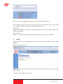
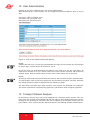
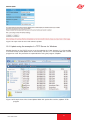
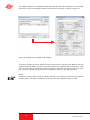
User Guide
U 262 ASI / IP Gateway
User Guide U 262
Copyright Notice
Parts of the software of this product is third-party software, which was developed under
several different licensing conditions. Detailed information concerning the licenses is provided using the webinterface of the device.
The source code of the free parts of the software is distributed on request for an administration fee.
Please contact:
[email protected]
ASTRO Strobel Kommunikationssysteme
Olefant 1-3
D-51427 Bergisch Gladbach (Germany)
Tel.: (+49) 2204 405-0
All other parts of the software of this product is Copyright by Astro Strobel Kommunikationssysteme GmbH.
Pictograms and safety instructions
Pictograms are graphical symbols with a defined meaning. You will find the following pictograms in these instructions for installation and use:
These symbols alert you to situations in which there is mortal danger as a result of dangerous voltage or noncompliance with these instructions.
This symbol alerts you to various health, environmental and material risks.
Recycling: all of our packaging (cardboard, paper inserts, plastic films and bags) is fully
recyclable.
Used batteries should be disposed of at approved recycling stations. This requires the batteries to be completely discharged when handed in.
Electronic equipment should not be placed in household garbage but rather - pursuant to
guideline 2002/96/EC FROM THE EUROPEAN PARLIAMENT AND THE COUNCIL dated
January 27, 2003 relating to old electrical and electronic appliances - should be disposed of
in a competent manner. Please hand in such equipment for disposal at the relevant public
collection stations when you have finished using it.
User Guide U 262
Inhaltsverzeichnis
1
2
3
4
5
6
7
8
9
10
11
12
13
14
15
16
17
18
19
20
Illustrations.............................................................................................................. 4
Introduction.............................................................................................................. 5
2.1 Safety instructions............................................................................................ 5
2.2 Assembly instructions....................................................................................... 5
2.3 Equipotential bonding/grounding....................................................................... 5
2.4 Servicing and repair...................................................................................... ....6
2.5 Technical data on the power supply................................................................. 6
General introduction..........................................................................................................7
3.1 Connecting the U 262 to a PC/Laptop............................................................... 7
3.2 The web browser user interface........................................................................ 7
Login...................................................................................................................................8
Settings..............................................................................................................................9
5.1 Setting the IP interfaces...........................................................................................9
5.2 Setting the IP Management interfaces..................................................................10
5.3 Storing and loading settings/reboot.......................................................................10
Test Generator................................................................................................................11
Configuring the input multiplexer...................................................................................11
IP setting for transmission and reception mode...........................................................12
IP setting for transmission port......................................................................................13
9.1 Transmit port............................................................................................................13
9.2 Destination IP..........................................................................................................13
9.3 Destination MAC......................................................................................................14
9.4 Type Of Service/Time To Live................................................................................14
9.5 LAN Tags.................................................................................................................14
9.6 TS Packets Per Frame/RTP/FEC............................................................................14
IP setting for reception ports..........................................................................................15
Configuring the output multiplexer.................................................................................17
User Administration.........................................................................................................18
Transport Stream Analysis.............................................................................................18
Licensing..........................................................................................................................20
Update..............................................................................................................................20
15.1 Update using (T)FTP Server.................................................................................20
15.2 Update using the example of a TFTP Server for Windows................................21
Log Book..........................................................................................................................23
Statistics...........................................................................................................................24
Network properties..........................................................................................................25
Logout..............................................................................................................................26
Technical Data.................................................................................................................27
User Guide U 262
3
1 Illustrations
Power LED
BNC ASI input
Warning LED
Failure LED
Display of
Management
IP addresses
MAC address sticker
Data ports
BNC ASI outputs
Mains supply
Grounding connection
Management ports
4
User Guide U 262
2Introduction
2.1 Safety instructions
Remove both mains plugs before opening the device!
Exercise caution when servicing the power supply unit. There is the risk of making contact with
parts which are live even when disconnected from the mains!
Operating indicators - where present - merely indicate the presence of DC voltages isolated from
the mains which supply power to the components of the device. However, operating indicators
which are not lit do not under any circumstances mean that the device is completely disconnected
from the mains or non-live.
Both mains switches or mains plugs are used as a mains isolator and must therefore be accessible and able to be used at any time. When just one power supply unit is connected to the operating voltage and the mains switch is set to „on“, the device is in operation. If the second power
supply unit is also put into operation, one operates in idle mode for as long as the other power
supply unit is supplying power to the device.
The device must be opened only by authorized specialist personnel inspected by the Chamber
of Industry and Commerce. The device must be repaired only by authorized specialist personnel
inspected by the Chamber of Industry and Commerce, or by sending it to ASTRO with the precise
description of the fault.
The mains cable(s) must be replaced only with original mains cables. Fuses must be replaced
only with fuses of the same type, value and melting characteristic.
Always observe:
DIN VDE 0701 - Parts 1 and 200, maintenance
EN 50 083 - Part 1, safety requirements
Do not carry out servicing work during thunderstorms
2.2 Assembly instructions
Protection from environmental influences:
The device must be connected and operated in dry rooms only. It must not be exposed to spray,
water droplets or similar influences. If condensation has formed, wait until the device has completely dried out. Objects filled with liquid must not be put down on the device.
The permitted ambient temperature is 0 ... 45°C.
Assembly environment:
The device is intended for operation in 19“ racks, which are preferably metallically conductive
and which have sufficient air convection. It should be operated away from radiant heat and other
heat sources. The device must be installed only in rooms in which the permitted ambient temperature can be maintained even if the climatic conditions change. To avoid trapped heat, it must be
ensured that air can circulate freely on all sides. Assembly in niches and unintentional covering of
the ventilation holes must be avoided at all times.
2.3 Equipotential bonding / grounding
User Guide U 262
5
The subscriber network must be and remain grounded as per the regulations in EN 60728 Part
11, even if the device is removed.
The equipotential bonding on the U 262 is provided by means of the fixing straps on the device
or by means of the grounding clamp on its back. Appliances within arm‘s reach must be mutually
integrated into the equipotential bonding.
Operation without connection to a protective conductor, device grounding or device equipotential
bonding is not permitted!
2.4 Servicing and repair
Caution:
The device must not be opened by the user, since the device does not contain any user-serviceable parts!
If all instructions are observed and the device is used as stipulated, no servicing is required.
Repairs must be carried out exclusively in the factory.
2.5 Technical data on the power supply (U 262)
Mains voltage: 100 – 240 V~
Mains frequency: 50 / 60 Hz
Power consumption:0,19 – 0,34 A per power supply unit
Degree of protection according to EN 60529: IP 20
Max. device ambient temperature: 45°C
Mains fuses: T2A L 250V
The U 262 must be operated only with the original power supply unit!
6
User Guide U 262
3
General introduction
3.1 Connecting the U 262 to a PC / Laptop
Applying the operating voltage turns on the U 262 automatically. Following the boot phase
(approx. 30 seconds), the display shows the two Management IP addresses (lines 2 & 3), and
any error messages (line 4).
If the device is connected to a PC / laptop by means of one of the network ports and once the PC/
laptop has been appropriately configured by means of the network settings, configuration of the U
262 can be started following input of the IP address in the address line of the Web browser.
3.2 The web browser user interface
The web browser user interface is split into a topframe, leftframe and mainframe.
The topframe
contains general information about the gateway.
Figure 1: General information in the topframe of the Web browser user interface
This information can be read as follows:
„SW: Jul 8 2008“ is the description of the software level on the U 262 Gateway,
„FW 1.4“ is the level of the firmware in the U 262 Gateway,
„HW: 2“ is the Gateway‘s hardware version,
„Up: 0d 00:03‘25““ is the connection time measured from the instant of logging in,
„Time (UTC):“ indicates the time on the U 262.
In the above figure, alignment with the SNTP server has not yet taken place, and the U 262
therefore indicates the year 1970. The bold line for „Location“ and „Contact“ is obtained from the
settings in the chapter „User Administration“.
The right-hand part of the topframe reflects the display and the status LEDs of the U 262, i.e. the
Web browser user interface reproduces the exact view of the U 262.
User Guide U 262
7
Figure 2: View of U 262 display and LEDs in the Web browser user interface
In the example for figure 2, the device is reporting the error „IP RX4A Data Loss“, and precisely
this error message can also be seen in the display of the U 262.
The leftframe
contains the navigation bar through the various submenus, which are described in detail in the
chapters which follow.
The mainframe
displays - in line with the selection in the navigation bar in the leftframe - the submenu.
4
Login
Before the Gateway can be configured, it is necessary to log in. This is done using the „Login“
submenu.
Figure 3: Input mask for login
Clicking on the „Login“ submenu opens the input mask for login (see figure 3). The standard
factory setting is:
„Username: admin and password: astro“
8
User Guide U 262
When the access data have been input correctly, it is possible to continue configuration. For
security reasons, the usernames and passwords as set by the factory should be changed. This
allows unauthorized access to be prevented. Only one user/BC 4 can ever be logged in on the U
262 Gateway. The very bottom of the leftframe of the Web browser user interface shows which
user is currently logged in.
5
Settings
Clicking on the „Main“ submenu takes you to the basic settings of the U 262.
NOTE:
All settings made must be transferred to the Gateway, and therefore activated, using the „Submit“ button. To save the data, make sure that you click on the „Save“ button after all parameters
have been configured, otherwise the settings which have been changed will be lost following a
reboot.
5.1 Setting the IP interfaces
The „IP Interface Settings“ area is used to make the settings for the four IP interfaces (Management A & B, and Data A & B).
The „MAC“ line displays the Mac address of the respective IP interface. The lowest Mac address
is required for licensing further features of the U 262 (see the chapter „Licensing“).
The „Active“ line can be used to activate and deactivate the individual IP interfaces, and the
„Mode“ line displays the bandwidth of the IP interface connected to the U 262. This bandwidth is
recognized by the U 262 automatically.
Figure 4: Detail from basic settings of the U 262: IP Interface Settings
The IP addresses („Address“ line), subnetwork masks („Subnet“ line) and standard Gateways
„Gateway“ line) are input using the keypad. Normally, it is only necessary to input a Gateway
under Management A.
NOTE:
Please use different IP addresses for every interface and different address ranges if the interfaces
are connected to different network segments. Input 0.0.0.0 for unused or unknown Gateways.
User Guide U 262
9
5.2 Setting the IP Management interfaces
The „IP Management Settings“ area is used to stipulate the DNS server, to configure up to four
SNMP Trap recipients and to input two SNTP servers for obtaining the time reference. The time
source used may then be „SNTP Server“ or „IP Rx 1“ to „IP Rx 16“ or „ASI TP“. Only the licensed
„IP Rx“ can be used.
Figure 5: Detail from the basic settings of the U 262 „IP Management Settings“
NOTE:
Please use different IP addresses. Input 0.0.0.0 for unused or unknown DNS, SNMP or SNTP
addresses.
5.3 Storing and loading settings / reboot
The „Save“ button is used to save all settings made in the flash memory and to restore them even
after mains failure or a reboot. The „Load“ button is used to restore the last operating parameters saved in the flash memory and to reject changes which were made previously and were not
stored.
Figure 6: Detail from the basic settings of the U 262 „Save, Load, Default & Reboot“
„Default“ is used to restore the factory settings, and „Reboot“ prompts the advice to restart with
the operating parameters saved in the flash memory.
10
User Guide U 262
6
Test generator
Clicking on the „Test Gen“ submenu takes you to the test generator settings. This internal test
generator is able to produce a test signal in order to perform a connection test, for example, and
to test this connection using a data stream.
Figure 7: Configuring the test generator
The generated data stream comprises zero packets with a length of 188 and can be configured
in a range from 1 - 197 Mbps. If the system contains several U 262 Gateways, a packet ID can
be allocated to distinguish the test signals.
7
Configuring the input multiplexer
Clicking on the „Input Mux“ submenu takes you to the input multiplexer settings. It is possible to
assign one ASI input stream to different IP TX. It is not possible to assign several ASI streams
to one IP TX (no multiplexing of IP multicast groups out of several ASI streams). The U 262 has
16 ASI inputs which can be used - depending on licensing - to convert a maximum of 16 IP data
streams.
Figure 8: Configuring the input multiplexer
User Guide U 262
11
The „Input Mux Settings“ are used to assign an IP TX port to each ASI input of the U 262 Gateway.
An ASI stream can also be routed to several IP TX, so that the U 262 can also be used as an IP
splitter. To provide a better overview, the respective row and column of the output matrix will get
a red background if the mouse pointer will be shifted over it. The ASI signal can also be inverted.
Please consider that the ASI signal has to be available in packet (burst) mode.
8 IP setting for transmission and reception mode
Clicking on the „IP TX & IP RX“ submenu takes you to the settings for the transmission and
reception modes of the U 262. This page provides an overview of the transmission port (IP TX) of
the U 262, the general settings of the reception ports (IP RX Common Settings) and the detailed
settings of the reception ports (IP RX Channel Settings).
Figure 9: Overview of the configured transmission ports
The overview shows the configuration of the individual transmission ports. The U 262 Gateway
in the above example is equipped with 16 reception licenses, i.e. 16 ASI input streams can be
converted to 16 IP multicast groups and be distributed over the network interface. The links “TX1”
to “TX16” take you to the detailed configuration of the respective port.
The transmission ports can be activated and deactivated in this mask, specifically differentiated
according to Data A and Data B interface. If the user has a redundant network infrastructure (e.g.
bidirectional backbone), it may make sense for the data to be transmitted via both data interfaces.
For the general settings of the reception port, it is possible to choose between “Data A” and “Data
B” as the active reception interface.
12
User Guide U 262
Figure 10: General settings for the reception ports (IP RX Common Settings)
If the network infrastructure is of redundant design and if “Data A” and “Data B” have the same
signal applied to them via a different supply line, the U 262 Gateway can be configured such that
in the event of a signal loss the active data port is automatically switched over (“Automatic” selection). If this redundant supply line does not exist, the “Static” option should be selected.
9
IP setting for transmission ports
NOTE:
The transmission ports should be configured in agreement with the network administrator in order
to ensure that no problems in the network occur!
Clicking on the “IP TX 1” to “IP TX 16” submenu takes you to the IP settings for the transmission
port.
9.1
Transmit port
The “Transmit Port” line can be used to select the port which is used to send the multicast
group.
A value ≥ 1024 should be set for this in order to avoid conflict with services (Port 21: FTP, Port
80:
http, Port 110: POP3 etc.).
9.2
Destination IP
The “Destination IP:Port” line is used to assign an IP address and a UDP port to the ASI transport
stream converted according to IP. Usually, a multicast address is input here, since this allows
the data stream to be received by several IP receivers. By contrast, a unicast address can be
received only by one IP receiver.
Multicast addresses are in the IP address space 224.0.0.0 to 239.255.255.255, the range
224.0.0.0 to 224.0.0.255 being reserved for administrative purposes.
User Guide U 262
13
Figure 11: Configuring the transmission port (IP TX1 to IP TX16 Channel Settings)
9.3
Destination MAC
The “Destination MAC” is obtained automatically from the input “Destination IP:Port” and is
displayed here as additional information.
9.4
Type of Service / Time to live
The “TOS/TTL” line provides the option of inputting the “Type Of Service” and the “Time To Live”.
Should the various services not be distinguished in the given network, it is not necessary to alter
the settings ex factory. The TTL indicates the permitted number of hops via a router and should
be defined such that the data packets cannot leave the network.
9.5
VLAN Tags
If the U 262 Gateway is intended to cover various VLANs, it is possible for the data packets to be
assigned different VLAN tags. This ensures that data packets are routed only to the desired
VLANs, or each VLAN receives only the data packets which are intended for it.
9.6
TS packets per frame / RTP / FEC
The format of the IP data stream can be determined in the bottom part of the table shown in figure
12. The number of transport stream packets per Ethernet frame can be stipulated between 1
and 7. In networks in which secure data transmission is ensured (e.g. proprietary backbone), the
number of packets can be set to 7, since the loss of an Ethernet frame is improbable. In networks
with nonsecure data transmission, a small value needs to be chosen in order to minimize the loss
of useful data in the event of an Ethernet frame being lost.
The “Protocol Encapsulation” line can be used to append an additional RTP header (Real Time
Transport Protocol) to the connectionless UDP/IP Ethernet frame. This header allows the individual transmitted Ethernet frames to be numbered in order to detect Ethernet frames which have
been lost or have arrived in the wrong order on a receiver. Error correction is not included by the
RTP header.
The U 262 Gateway is equipped with an optionally engageable FEC. This FEC forms checksums
from a matrix and transmits these checksums to the UDP ports + 2 and + 4 in the same multicast
group. When the data are recovered, these checksums are aligned and errors can be corrected.
Two different modes of FEC are possible: one-dimensional FEC, in which sums are formed only
over the columns, and two-dimensional FEC, in which the sums are formed over columns and
rows.
Figure 12: Configuring the FEC
14
User Guide U 262
The first drop-down selection field is used to stipulate the number of columns in the checking
matrix. There are 1 to 20 columns or the selection “Off” available here. The second drop-down
selection field is used to stipulate the number of rows in the checking matrix. There are 4 to 20
rows or the selection “Off” available here. The third selection field is used to select one-dimensional or two-dimensional FEC (Col+Row = two-dimensional/Col only = one-dimensional over
columns).
The mode of the FEC can be selected to be “Plain”, “Annex A” or “Annex B” in line with ProMpeg
COP3 (SMPTE 2022-1). Please note that plain FEC results in a burst behavior for the data rate,
and hence Annex A and Annex B are preferable. It should be noted that the product of the number
of columns (L) and the number of rows (D) is ≤ 100 (L x D ≤ 100).
10 IP setting for reception ports
Clicking on the „IP RX1-1 - IP RX16“ submenu takes you to the IP settings for the desired reception port.
Figure 13: Setting details for the reception port
The “Receive IP:Port” line is used to input the IP address and the UDP port at which the U 262
Gateway needs to receive the data stream.
User Guide U 262
15
The “Encapsulation” is selected according to the stipulation of how the input data stream has
been encapsulated by the transmission equipment. In RTP mode, every data packet must be
provided with an RTP header. This header contains numbering for the individual transmitted Ethernet frames in order to detect and possibly re-sought Ethernet frames which have been lost or
have arrived in the wrong order on the receiver. Error correction is not included in the RTP header
(RTP: can only receive RTP frames / UDP can receive both but cannot use the RTP header).
A data stream can arrive with a CBR (Constant Bit Ratio) in the U 262 Gateway, or with a VBR
(Variable Bit Ratio). In any case, CBR is used for MPTSs (Multiple Program Transport Stream)
but also for SPTSs (Single Program Transport Stream). However, SPTSs can also be sent with
a VBR.
Under “Packet Mode”, it is possible to select between “continuous” or “burst” for configuring the
respective ASI output connected downstream of the IP RX.
The TSIDs and ONIDs are displayed for information purposes in line with the selected transport
stream and, to provide a better overview of the transport streams, it is possible for an alias to be
input. If no alias is input, the name of the first service of the transport stream is entered automatically.
16
User Guide U 262
11 Configuring the output multiplexer
Clicking on the “Output Mux” submenu takes you to the output multiplexer settings
Figure 14: Example view of the output multiplexer
The received IP RX is supplied via the BNC socket on the front and can be inverted prior to conversion to ASI (inversion on / off). In addition the packet length can be determined to 188 or 204.
There is also the possibility to bypass one of the 16 ASI streams from the backplane to the BNC
socket on the front panel as well as the internal test generator signal (see chapter 6)
User Guide U 262
17
12 User Administration
Clicking on the „User“ submenu takes you to User administration.
When delivered, the U 262 Gateway can be configured using three different items of access
data.
Username: admin, password: astro
Username: user, password: astro
Username: bc4, password: astro
Figure 15: View of User Administration upon delivery
NOTE:
ASTRO does not have a master password! Should you forget your password, you will no longer
be able to log in and the device will need to be sent in.
No service levels are distinguished for the different users. Each user has the same rights. To
remove user accounts 2 to 4, it is merely necessary to input a blank username and click on the
„Submit“ button. New passwords which are input must not be shorter than 5 characters.
NOTE:
All settings made need to be transferred to the Gateway and activated using the „Submit“ button.
To save the data, make sure that you click on the „Save“ button in the „Main“ submenu, otherwise
the settings which have been changed will be lost following a reboot.
The data which have been input under „Location“ and „Contact“ are displayed in the topframe.
This makes it possible to avoid confusing appliances and locations when configuring remotely.
13 Transport Stream Analysis
By purchasing a license, the U 262 can be equipped with a transport stream analyzer. This analyzer shows the structure of the MPEG2 TS from the tables to the individual PID and its service.
Clicking on the „TS Analyzer“ submenu takes you to selection of the transport stream to be analyzed. When a TS is selected and the „Submit“ button hit, the following example window opens:
18
User Guide U 262
Figure 16: Analyzing the selected transport stream
Wait until the „...done!“ message appears. Clicking on the „+“ or „-“ symbols displays or hides the
details. Through selection of the „ASI TP“ as the TS to be analyzed, the TS analyzer also provides
the option of analyzing externally applied ASI signals.
User Guide U 262
19
14 Licensing
Clicking on the „License“ submenu takes you to licensing. The features of the U 262 can be
upgraded from the factory-delivered state (1 IP TX & 1 IP RX) through to the full complement of
equipment (16 IP TX, 1 IP RX and TS analyzer) by purchasing software licenses.
Figure 17: Input mask for software licenses
A prerequisite for ordering further licenses is provision of the Mac address of the device. The Mac
address can be found either on the sticker on the back of the device (see illustrations on page
3) or in the Web browser interface. In this respect, the lowest Mac address is the important one.
When the Mac address has been provided, ASTRO will generate the license keys and supply
them by E-mail or on CD.
The format of the license keys is a text document (e.g. Lic001772000222.txt). The key or keys can
be inserted into the input mask using „Copy/Paste“, and clicking on the „Submit“ button transfers
the license to the U 262 Gateway. If the license is valid, this is confirmed by a message. An invalid
license is indicated by an error message.
15 Update
15.1 Update using (T)FTP Server
Clicking on the „Update“ submenu takes you to the settings for the U 262 software update. The
„(T)FTP Server address“ line is used to input the (T)FTP server address at which the current
software for the U 262 Gateway is stored.
The „Protocol“ line provides the option of selecting „FTP“ (File Transfer Protocol) or „TFTP“ (Trivial File Transfer Protocol). If the „TFTP“ option is chosen, it is not necessary to input the username
and the password.
„Path“ is used to input the path on which the U 262 software update was stored. It is necessary to
ensure that the software is stored in the indicated path (preceded and followed by „/“), otherwise
the update will not take place. Furthermore, it must be ensured that any firewall installed permits
the (T)FTP communication. In the „Update“ submenu, it is also possible to store the configuration
of the U 262 Gateway on an FTP server, or else to load a configuration into the U 262 Gateway.
Loading a configuration into the U 262 Gateway does not affect the settings of the IP interfaces.
.
20
User Guide U 262
Figure 18: Input mask for the U 262 software update
15.2 Update using the example of a TFTP Server for Windows
Should there be no firm (T)FTP server set up for updating the U 262 Gateway, it is also possible
to transfer locally stored update files to the Gateway. For this, it is recommended that a TFTP
program be used. The procedure is explained below using the program „Tftpd32“.
Figure 19: Example view of the U 26x Update folder with update files and the „tftpd32“ TFTP
program
User Guide U 262
21
The „tftpd32“ program is started directly from the folder with the U 262 update files. In the window
that opens, click on the „Settings“ button first and make the settings as shown in Figure 21:
Figure 20: Settings for the tftpd32 TFTP program
To start the update, the server address which is input into the „(T)FTP Server address“ line now
needs to be the IP address of the local computer (Figure 19), and the protocol needs to be set to
TFTP. It is therefore also no longer necessary to input a username and a password. In the „File“
line, select the „Update“ option, and start the update by clicking on the „Submit“ button.
NOTE:
A reboot or network failure during an update procedure can result in the U 262 Gateway software
crashing fatally. The device would then need to be sent to the ASTRO factory for repair.
22
User Guide U 262
16 Log Book
Clicking on the „System Log“ submenu takes you to the U 262 Gateway‘s log book. This documents all processes which are relevant to operation.
Figure 21: Example view of the U 262 log book
The processes are sorted according to the time of occurrence. The logfile is erased by checking
„Check box to clear log on refresh“ and then clicking on the „Refresh“ button. The first entry in the
log book will then be the erase process with an indication of the time and the user account, and
also the IP address of the user.
NOTE:
Download the system settings using the „status.xml“ link; store the configuration as a table using
the „log.csv“ link.
Figure 22: View of the log book following erasure
User Guide U 262
23
17 Statistics
Clicking on the „Statistics“ submenu takes you to the statistics relating to the data transfer of the
U 262 Gateway. This displays all statistics which are relevant to operation and which can be used
for analysis.
Figure 23: Statistics for U 262 data transfer
24
User Guide U 262
18 Network properties
The network properties can be displayed by clicking on the „Network“ submenu. The displayed
characteristics are purely informative and serve to describe the network.
Figure 24: Example view of the network properties in the „Network“ submenu
User Guide U 262
25
19 Logout
Clicking on the „Logout“ submenu (only available when you are logged in) allows you to log out
from the U 262 Gateway.
Figure 25: Logging out from the U 262 Gateway
If you confirm the question using the „Yes“ button, you are logged out. It is not possible to make
any further settings without logging in again, but it is possible to view the U 262 Gateway‘s settings. The setting items are inactive, however.
26
User Guide U 262
20 Technical Data
Type
Order number
U 262
U 262 i
380 263
380 264
Transport stream interfaces
DVB ASI
16
Connectors
Bitrate
BNC jack
[Mbit/s]
213, maximum
Network interfaces
Interface type
1000 Base-T Ethernet
IEEE802.3 Ethernet, RTP, ARP, IPv4, TCP/UDP,
HTTP, SNTP, IGMP
Protocol
Connector
2 x RJ 45
Total bitrate
[Mbit/s]
700, maximum
Ethernet MTU-length
[bytes]
1500, maximum
Stream processing
TS Encapsulation
UDP, UDP+RTP, 1-7 packets, FEC
Stream processing
transparent (188 oder 204 packets)
Control and management
Type
10/100 Base-T Ethernet
Features
Element control through HTTP/WEB,
Protocol
HTTP, SNMP (error messages)
Connectors
2 x RJ 45
Common data
Input voltage
Power consumption
[VDC]
230 V
- 48 V
[W]
22
17
Dimensions
Ambient temperature
User Guide U 262
1 HE / 19“
[°C]
0…+50
27
82 293 400 07/2010 DE
ASTRO Strobel Kommunikationssysteme GmbH
Olefant 1–3, D-51427 Bergisch Gladbach (Bensberg)
Tel.: 0 22 04 / 4 05-0, Fax: 0 22 04 / 4 05-10
eMail: [email protected], www.astro-kom.de