1
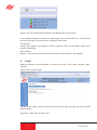
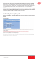
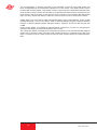
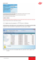
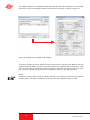
Figure 11: Configuring the transmission port (IP TX1 to IP TX16 Channel Settings)
9.3 Destination MAC
The “Destination MAC” is obtained automatically from the input “Destination IP:Port” and is
displayed here as additional information.
9.4
Type of Service / Time to live
The “TOS/TTL” line provides the option of inputting the “Type Of Service” and the “Time To Live”.
Should the various services not be distinguished in the given network, it is not necessary to alter
the settings ex factory. The TTL indicates the permitted number of hops via a router and should
be defined such that the data packets cannot leave the network.
9.5 VLAN Tags
If the U 262 Gateway is intended to cover various VLANs, it is possible for the data packets to be
assigned different VLAN tags. This ensures that data packets are routed only to the desired
VLANs, or each VLAN receives only the data packets which are intended for it.
9.6
TS packets per frame / RTP / FEC
The format of the IP data stream can be determined in the bottom part of the table shown in figure
12. The number of transport stream packets per Ethernet frame can be stipulated between 1
and 7. In networks in which secure data transmission is ensured (e.g. proprietary backbone), the
number of packets can be set to 7, since the loss of an Ethernet frame is improbable. In networks
with nonsecure data transmission, a small value needs to be chosen in order to minimize the loss
of useful data in the event of an Ethernet frame being lost.
The “Protocol Encapsulation” line can be used to append an additional RTP header (Real Time
Transport Protocol) to the connectionless UDP/IP Ethernet frame. This header allows the individual transmitted Ethernet frames to be numbered in order to detect Ethernet frames which have
been lost or have arrived in the wrong order on a receiver. Error correction is not included by the
RTP header.
The U 262 Gateway is equipped with an optionally engageable FEC. This FEC forms checksums
from a matrix and transmits these checksums to the UDP ports + 2 and + 4 in the same multicast
group. When the data are recovered, these checksums are aligned and errors can be corrected.
Two different modes of FEC are possible: one-dimensional FEC, in which sums are formed only
over the columns, and two-dimensional FEC, in which the sums are formed over columns and
rows.
Figure 12: Configuring the FEC
14
User Guide U 262