1
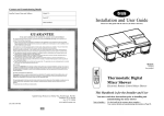
Selectronic
Premier
Thermostatic Instantaneous Electronic Shower
Handbook
Temperature
Selectronic
Premier
Temperature
Lock
After Sales Service
Warmer
We offer a technical advisory service on the telephone to installers and other customers with problems
in the field.
I
Cooler
RING 0844 372 7766 (UK ONLY)
I
Remember to quote type of shower, as written on the front of the shower and on this leaflet.
I
The model and serial number are located on the bottom face of the shower.
Make a note of those numbers here, and be sure to quote them if you call for advice.
I
Model Number: 53--__________________ / Serial Number:____________________
Note: You may be charged for a service call if you do not have the serial number.
Start/Stop
Full details of terms and conditions are available on request from:-
IMPORTANT
Applied Energy Product Ltd, Morley Way, Peterborough, PE2 9JJ
Website: www.redring.co.uk
A3:567-2300-01B
24
This booklet should be given to the customer
after installation and demonstration
01-07-2010
Selectronic Premier
Selectronic Premier Plus
(with 1.25m Hose)
(with 2m Hose)
1120 mm
264 mm
Temperature
Temperature
Selectronic
Premier
Temperature
Lock
Warmer
Cooler
Temperature
Lock
674 mm
364 mm
Selectronic
Premier
Warmer
Cooler
Start/Stop
Start/Stop
2
23
Contents
Installer Information;Product Dimensions
Installation Instructions
Plumbing Connections
Electrical Connections
Changing The Operation Mode
Templock/Normal
Changing ‘DIP Switch’ Default Setting
Commissioning
Trouble Shooting (Installer)
BEAB Care Wash Scheme
Spares
Page
2
3
5
7
User Information
Product Dimensions
How To Use Your Shower
How Your Shower Works
Handset Operation
Routine Maintenance
Periodical Maintenance
Trouble Shooting (User)
BEAB Care Wash Scheme
Guarantee
9
9
11
19
20
21
Installation Instructions
A TYPICAL INSTANTANEOUS ELECTRIC SHOWER INSTALLATION
ALL WIRING AND INSTALLATION MUST BE
SUPERVISED BY A SUITABLY QUALIFIED
PERSON.
We recommend that the installation be done in
the following sequence: a) Fix the shower to the wall
b) Plumbing
c) Electrical connections
d) Commissioning
Warning! Do Not Install The Shower In A
Room Where It May Be Subject To Freezing
a) Fix The Shower To The Wall
(To assist, a mounting template is printed on
the shower carton - “Selectronic-Plus” only)
When deciding where to place the unit a few
things need to be taken into consideration: 1) The unit must not be mounted directly in
the path of the spray from the handset
2) The handset could be used over a sink for
hair washing.
3) The handset does not come into contact
with the used water in the cubicle, bath or
basin.
A hose retainer is supplied with the
Accessories (See Diagrams 25 & 26).
4) The unit can be mounted at a lower level for
less able users combined with optional
extended hose and riser rail.
The installation must comply with BS 8300:
2001.(Design of buildings and their
approaches to meet the needs of disabled
people. Code of practice).Remembering to
Adhere to point 1.
5) Choose a flat piece of wall to avoid the
possibility of distorting the backplate and
making the front cover a poor fit.
22
Page
2
12
15
17
17
18
18
21
24
3
Remove the four cover screws and lift the
cover off.
Typical guideline dimensions used for
less- abled bathroom installations
Remove the four inlet cover screws and remove
inlet cover - also the two side access trimplate
section screws and remove complete with seal.
1000
Having determined the direction of the inlet
water mains supply and cable approach for
the installation (Top, Bottom, or Rear or any
combination) - it is necessary to remove the
appropriate section inserts. See Plumbing
Connections and Electrical Installation
sections (Pages 5 and 7) for detailed guidance.
Back
Rest
Hold the shower vertically against the wall and
mark the top hole first.
480
Drop-down rail on side wall
Drill the hole to take the rawl plug provided
(taking care to keep dust away from the
shower).
Alarm Pull Cord
Please Note:- The fitting of all spares should be supervised by a suitably qualified person
Part No,
Description
Part No.
Description
93594102
93594104
93594105
93594117
93594135
93594136
93594137
93594138
93594139
93594140
93594141
93594142
Triac PCB
Flow Valve Assy (No Outlet)
Valve Stepper Motor
Flow Transducer
Front Cover Complete
Heat Exchanger 8.5kW
Heat Exchanger 9.5kW
Heat exchanger 10.8kW
Thermal Cut-Out c/w Cables
Outlet Connector c/w Temp Sensor
Cable/Pipe Entry Set
PRV Housing Complete
93594143
93594144
93594145
93594146
93593578
93797641
93550865
93593522
93550834
93593526
93550864
93593580
Main Logic Board
Inlet Filter Housing Complete
Backplate Trimplate
Backplate Side Section
6-Mode Handset
1.25m Long Chrome Shower Hose
2m Long Chrome Shower Hose
Wall Bracket Set (Std Models)
Wall Bracket Set (Plus Models)
22mm x 455mm Bright Riser Rail
22mm x 1m Bright Riser Rail
Height Adjuster Assy
Elevation
Diagram 25
Shower
Unit
2000
Shower Riser
Rail
Towel / Grab Rail
1200
Tip Up Seat
500
Floor
Drain
350
Position the shower so that it is vertical then
mark and drill the other two holes. Then fix the
Shower to the wall.
Diagram 26
300
850
Put the top screw in first leaving it proud by
5mm approximately. The shower can now be
hung on this screw.
Assemble the accessories as shown in
Diagram 25 (or 26 for ‘Plus’ model Accessories).
Fix the riser rail with screws provided.
The fixing holes are revealed by removing the
plastic fronts.
Handset Height Adjustment
Spares (Ring 0844 372 7750 UK ONLY)
Drop-down
Rail
650
Shower Curtain
1200
Note: For “Plus model accessories” ensure that
the notch in the riser rail is fully engaged into
the corresponding lug in the wall bracket. This
has been made a firm fit to aid stability and stop
rotation.
Fall of Floor
Plan
1500x1500 Wheelchair Turning Space
All measurements shown are in millimetres. Drawing sizes are
not to scale. Shower model shown is a Selectronic Premier Plus.
4
21
I
I
g) Temperature buttons have a limited
adjustment range.
Unit is in Temp/Lock mode. Remove cover and change
position of templock switch to ‘4’ (see Diagram 8 for
location) or explain feature to user.
Note: For Care Wash installations the Temperature Lock
Switch MUST be set to 1 or 2.
I
I
h) Shower runs for about 5 seconds and
then switches OFF by itself.
Flow transducer fault.
Check that internal blade “spins” when the water flows:
If not, replace transducer.
Plumbing Connections
C
Plumbing to be carried out before wiring
DO NOT use jointing compounds on any pipe
fittings for the installation.
DO NOT solder fittings near the shower unit
as heat can travel along pipework and
damage components.
A
Compression fittings MUST be used to
connect to the inlet of the shower.
BEAB Care Wash Scheme
I
Note: For Care Wash Installations the Temperature Lock Switch
MUST be set to either 1 or 2.
I
For those installations where the BEAB Care Wash Scheme is required please refer to separate
handbook “Commissioning, In Service Testing and Maintenance if the Selectronic Premier Shower
for BEAB.
Diagram 2
Note: We recommended that a WRAS (Water
Regulations Advisory Scheme) listed isolating
valve be fitted between the rising main and
the unit. This will allow the unit to be serviced
without having to turn off the house water at
the stop valve.
The unit can be connected to the mains
COLD water supply. This must have a
minimum running pressure of 0.07 MPa
(0.7bar / 10 p.s.i.) and a maximum pressure
of 1MPa (10bar / 145 p.s.i.).
This unit can be fed from a header tank
provided this has a minimum head of 7 metres
(23ft).
B
Diagram 1
D
IMPORTANT: Before completing the
connection of the water supply to the inlet of the
shower, flush out the pipework to remove all
swarf and system debris. This can be achieved
by connecting a hose to the pipework and
turning on the mains water supply long enough
to clear the debris to waste.
A blockage in the waterways (particularly the spray
plate of the handset and solenoid valve) will prevent
the unit from working correctly.
The shower is designed to have an open outlet and
should ONLY be used with the fittings recommended
by the manufacture.
Installation Procedure
Turn off the water supply either at the mains
stopvalve or the isolating stopvalve.
For ease of access to the inlet fitting the right hand
side of the shower has a removable inlet cover. See
Diagram 1. Also remove the backplate side access
trimplate shown in Diagram 1.
20
5
Connect the mains water supply to the Inlet of the shower via 15mm copper, stainless steel or plastic
pipe using a 15mm compression fitting. See (Diagram 4) for advice on Rear Entry fitting.
The Inlet fitting is designed to rotate through 180° to allow for either Top or Bottom/Rear entry fitting
(See Diagrams 3).
Installation Note: The inlet fitting is designed to enter a compression fitting only. DO NOT use push
Fit connectors as full engagement cannot be guaranteed. DO NOT use excessive force when making
these connections.
Installation Note: If installing a water feed pipe from the back, the use of a soldered Elbow
Connector is recommended. It should be positioned approximately 87mm from the inlet connector
centre. The centre of the inlet connector to the wall surface is 21mm.
Diagrams 3
BOTTOM ENTRY
REAR ENTRY
If these fail to restore the performance you should seek professional help.
The person who installed the shower is probably the best one to repair it and is certainly the person
to contact if you have a problem in the guarantee period.
SELF HELP CHECK LIST
a) Water too HOT
Press the cooler button.
Clean spray plate holes on showerhead.
I
I
b) Water too COLD
Press the warmer button (See Page 9 For allowed
adjustment range) .
I
I
c) Spray pattern poor
Clean spray plate. Select Outer/Inner only.
I
I
d) Display behaves erratically
Switch OFF electricity at ceiling/wall isolating switch,
wait a few seconds, switch on again.
(Note: The shower should be switched OFF each
time after use at the ceiling/wall isolating switch.
I
I
REFIT THIS
SECTION
DISCARD
THIS
PART
e) Water does not flow when START/STOP Note: If there is no water flowing then the shower will
automatically switch OFF after about 5 seconds.
button is pressed.
I
I
Lights ON.
Check the water supply is turned ON.
I
I
“o” and “t” flashing in display.
Unit in over temperature mode see section on “purging”.
I
I
No lights.
Check ceiling/wall isolating switch is ON.
Check power is ON.
I
I
f) Warmer/Cooler buttons do not function.
Temperature range may be limited by Temp/Lock setting
setting (See Page 9)
I
I
g) Unit makes a whirring noise, especially
at the start of the shower session.
This is normal.
There is a motor inside the shower used to adjust the
flow and this always operates at the start of each shower.
PROFESSIONAL SERVICE CHECK LIST
This additional checklist is provided for the benefit of the qualified service representative.
WARNING! Switch Off The Electricity At The Isolator Before Removing The Front Cover To
Make Checks.
a) Poor temperature control.
REFIT THIS
SECTION
DISCARD
THIS
PART
IMPORTANT: The inlet
fitting MUST be used in the
Bottom fitting position for
Rear fitting. Under NO
circumstances must the
Inlet be rotated 90° and the
pipe fitted directly.
The shower has not been
designed for this method
of connection.
6
TOP ENTRY
Check inlet/outlet thermistors to see if they are in circuit.
Check for blockage in the inlet filter.
I
I
b) Water too COLD
Check circuit through thermal cut-out.
Check circuit through all 4 elements.
Test should be done using a low voltage resistance
meter whilst the power is switched OFF at the isolating
switch.
Check working voltage.
I
I
c) Poor or no control over water flow.
Replace inlet valve assembly.
I
I
d) No water when START/STOP button is
pressed.
Check water supply. Check circuit through solenoid coil.
If OK replace logic PCB.
I
I
e) Unit has been switched OFF using
START/STOP button but can be heard
heating the water.
Replace triac PCB.
I
I
f) Pressure relief valve operated.
Check for cause of high pressure and remove it.
Replace pressure relief valve. (Not covered under
Guarantee).
19
Shower Accessories :It is recommend that as well as checking the showerhead as detailed above, the shower unit, riser
rail, hose etc. be cleaned using a soft cloth and that the use of abrasive or solvent based cleaning
fluid be avoided, especially on any plated finishes.
We recommend that before any cleaning, the isolating switch be turned off, thus avoiding accidentally
switching on the shower.
You Must Regularly Inspect The Shower Hose For Wear And Damage. Replace If Necessary,
Or Every Two Years, With Our Approved Part.
Periodical Maintenance
Diagram 24
Cleaning the Filter
It is recommended that the filter is periodically
cleaned in order to maintain the performance
of the shower. It is essential that this operation
is carried out by a competent person.
If you are replacing an earlier model of the
Redring Selectronic you will need to remove
the appropriate backplate section subject to
whether the mains water plumbing approach
is either top or bottom entry. See Diagram 2
- Options ‘A’ or ‘B’.
For surface mounted Top entry for plumbing
remove and discard section ‘C’ and for the
Bottom entry option do likewise with section
‘D’.
Make sure the backplate is square on the wall
and tighten the retaining screws which hold it
to the wall.
87 mm
After use it is normal for some water to drip from the spray head for a few moments. This helps
prevent scale build up over prolonged use.
Turn ON the mains water supply and check for
leaks in the pipework connection to the
shower.
Note: At this stage no water can flow through
the unit.
IMPORTANT: Using a suitable sealant,
always seal around the incoming pipework
through the wall to prevent water entering
the wall.
WARNING! Switch OFF the electricity at
the isolating switch and the water supply
at the mains before removing the cover.
21 mm
Diagram 4
WARNING! The outlet of the shower
acts as a vent and MUST not be
connected to anything other than the
Hose and Showerhead supplied or
approved by the manufacturer
The inlet filter is situated inside the water inlet
fitting (See Diagram 24).
To gain access to the filter remove the cover
and right hand trim plate. When removing the
cover be careful that you DO NOT tug the
flying lead from the PCB which is attached to
the cover. Disconnect the flying lead from
the reverse of the front cover.
Electrical Connections
POWER
TRIAC
IN
OUT
TEMPS
The electrical installation must be in accordance with the current BS7671 (I.E.E. wiring
regulations) and “Part P” of the Building
Regulations and/or local regulations.
L
UMBILICAL
STEP
Inspect the ‘O’ rings on the filter body for any
damage when removed from the inlet assembly.
FLOW
N
The unit is designed for a single phase 50 Hz
a.c. electrical supply.
When cleaning the filter, DO NOT use a sharp
object, as it will cause damage. It is preferable
to use an old toothbrush or similar
SOLENOID
Refit the filter making sure it is screwed fully
home. Do not over tighten the filter cap on
reassembly.
HEAT EXCHANGER
A means for disconnection in all poles must
be incorporated in the fixed wiring in accordance with the wiring rules. We recommend
ceiling switches.
I
Troubleshooting
I
If the performance of the shower deteriorates in service, follow the checks in the “Self Help” table
below before calling out the contractor.
Any one of the simple adjustments could restore the performance.
18
INLET
THERMISTOR
FLOW
TRANSDUCER
The cable size required is determined by the
kW rating of the shower and the distance
between the shower and the consumer unit.
The table on Page 8 is for guidance only in
choosing the correct cable for your installation.
TRIAC PCB
COOLER
Please check the rating plate on the unit to
see what details apply to your unit.
Do not remove the filter mesh from the body
and clean whilst still in position.
E
TRIAC
Holding the filter body with a spanner across
the flats, unscrew the top cap on the water
inlet fitting using another spanner.
OUTLET
THERMISTOR
If on installation it is the intention to use YT2
conduit trunking to conceal the surface
electrical cable to either the Top or Bottom
STEPPER
MOTOR
Wiring Diagram
7
Handset Operation
entry points then the following backplate
component will need to be discarded allowing
for the conduit to fit into the backplate. See
Diagram 5 - Option ‘E’ or ‘F’.
Diagram 5
E
There are a number of defined spray plate
setting modes (patterns) adjustable by rotating
the spray plate (see Diagram 23).
CIRCUIT PROTECTION
Unit
Rating
MCB
These modes (patterns) have a positive click
to identify them.
Cartridge
Fuse
8.5kW
40A
I
I
I
9.5kW
40/45A
45A
I
I
I
10.8kW
45A
45A
The spray plate rotates through (360°) in either
direction to change the spray pattern.
45A
EXCITE
SENSUAL
(Single Centre Spray)
(Outer & Inner Spray)
Twin and earth PVC insulated cable
Current carrying capacity
Installed in an In conduit Clipped direct
insulated wall trunking or buried in a
non-insulated
wall
6 mm 2
32A
I
10 mm 2
43A
I
16 mm 2
57A
6 mm 2
38A
I
10 mm 2
52A
I
16 mm 2
69A
6 mm 2
46A
FRESH
ECSTASY
(Single Inner Spray)
(Outer Centre & Inner Spray)
I
10 mm 2
63A
I
16 mm 2
85A
Diagram 23
G
Note: Cable selection is dependent on
derating factors
If the installation requires the use of 10mm2 or
16mm2 cable up through the Bottom Entry
option, then you will need to remove the
appropriate backplate section ‘G’ shown in
Diagram 5.
F
TRANQUIL
ALLURE
(Single Outer Spray)
(Outer & Centre Spray)
Routine Maintenance
The cable connected to the appliance must be
fixed wiring, and should be stripped back as
shown in Diagram 7
Diagram 6
Handset:In Order To Maintain The Performance Of
Your Shower You Must Clean The Shower
Head Regularly.
Connect the cable to the terminal block.
Ensure that all the retaining screws are VERY
tight and that no cable insulation is trapped
under the screws.
All water contains particles of lime-scale,
which build up in the showerhead and unit
reducing the performance.
Warning! Failure To Comply With
These Instructions Could Result In
A Failure Of The Terminal Block.
It is therefore important to clean the
showerhead by simply rubbing the rubber
nozzles or soaking in proprietary lime-scale
remover and rinsing thoroughly before use.
Warning! This Appliance Must Be
Daily Cleaning
To break away scale on a
daily bases, rub your thumb
over the surface whilst the
shower is running.
Periodical Maintenance
If scale deposits are
stubborn, soak the shower
head in proprietary
limescale remover and rinse
thoroughly before use.
The frequency of this will vary from weekly to
quarterly depending on the water hardness and experience.
Earthed
Replace the inlet cover and side access
trimplate section complete with seal.
8
In some winter conditions, when the incoming mains water is particularly cold it may be necessary to
select the inner or outer spray pattern only; this will ensure correct operation of the shower with a
slightly lower water flow rate.
17
DIP
SWITCH
TERMINAL
BLOCK
WARNING
THIS
PRODUCT
MUST BE
EARTHED
IMPORTANT Connect flying lead from PCB
to rear of the front cover - see Diagram 6.
FIT EARTHING SLEEVE
Diagram 7
Replace the front cover and fasten in position
with four screws.
NEUTRAL
EARTH
LIVE
TEMPLOCK
SWITCH
LOGIC
PCB
THERMAL
CUTOUT
WARNING
HEAT
EXCHANGER
PRESSURE
RELIEF
VALVE
ENSURE POWER IS OFF BEFORE REMOVING COVER.
REPLACE THIS COVER PRIOR TO FRFITTING THE FRONT COVER.
5. A stabiliser is built into the flow
valve to automatically compensate
for small fluctuations in water
pressure that frequently occur in
households.
There are three further controls to
cater for exceptional reductions in
water pressure to prevent the
shower from getting too hot.
a) If the flow of water is less than
1.0 l/min the power to the
elements is switched off, but the
solenoid valve remains open
allowing water to flow through
the shower.
b) If the outlet temperature sensor
senses an excessive
temperature the flow of water
and the heating elements will
automatically switch off. The
electronics will signal over
Temperature condition (see
“over temperature shutdown”
section).
c) A two stage mechanical thermal
cut-out is mounted on the top of
the heat exchanger independent
of the electronics.
OUTLET
TEMP
SENSOR
55mm
SOLENOID
VALVE
INLET
COVER
POWER
PCB
BRASS
COOLER
FLOW
VALVE
OUTLET
Stage one switches the power
off to the elements if it senses
an excessive temperature.
The switch operates with an
audible click and will reset if
cold water is run through the
shower.
Stage two only operates if an
extreme temperature is sensed.
The cut out will permanently
switch off and it will then have
to be replaced.
FLOW
TRANSDUCER
10mm
MOTOR
Changing The Operating Mode
Templock/Normal
Diagram 8
LOCKED
POSITION
WARNING! Switch OFF the electricity
at the isolating switch before removing
the cover.
’1’
On the extreme right hand side of the PCB
mid way up is the ‘4 Way Temp Limit Slider
Switch’ (See Diagram 8).
LOCKED
POSITION
’2’
PLEASE NOTE! The Selectronic Premier is
factory set with the ‘Temp Limit Slider Switch’
set at ‘Locked Position 1’.
LOCKED
POSITION
’3’
After the unit is commissioned, you have the
option of choosing from any of three different
lockable temperature settings plus normal
operation position from left to right.
UNLOCKED
POSITION
’4’
Remove the front cover taking care not to strain
the flying lead.
Change the switch to the desired temperature
control position.
Locked Position 2
Locked Position 3
(Extreme Left)
(First ‘Click’ from
the Extreme Left)
34-41°C Nominal
(Second ‘Click’ from (Extreme Right)
the Extreme Left)
34-43°C Nominal 25-46°C Nominal
Temperature
34-40°C Nominal
Adjustment Range
6. A pressure relief device is fitted to
safeguard against abnormal
pressure conditions, and provides
a level of appliance protection
should an excessive build of
pressure occur within the shower.
If this operates a replacement part
will be required.
Unlocked Position 4
Locked Position 1
Replace and refasten the front cover.
Switch on electricity. Check that the unit operates correctly.
PLEASE NOTE! The Temperature Lock light on the front cover of the shower will not illuminate if
Normal Position 4 has been selected.
Changing ‘DIP Switch’ Default Setting
WARNING! Switch OFF the electricity at the isolating switch before removing the cover.
On the PCB directly to the left of the transformer there are two sets of vertically arranged ‘DIP
Switches’ (See Diagram 9) The top set of 3 are NOT TO BE CHANGED they are used for the shower
software configuration.
16
9
The second set of 3 mounted directly below are ‘Shower Control Feature Setting Options’ and can be
set to suit the requirements of user. The function and options for each ‘DIP Switch’ are shown below:Position ‘0’
(Switch to the Left)
Position ‘1’
(Switch to the Right)
DIP 1: Flow Optimiser Switch
Fixed Flow
Maximise Flow
DIP 2: Start-Up Temperature Setting
Preset Start-Up
Previous Setting
DIP 3: Maximum Flow Limiter
Flow Limited to 6 l/m max Flow Limited to 9 l/m max
PLEASE NOTE! The Selectronic Premier is
factory set with the ‘DIP Switch’ set as follows:I
I
Maximise Flow =
When the ‘DIP Switch’ is pushed to the
right the shower will use maximum
power at all temperature settings (Eco
Power OFF).
In order to stop the shower automatically
switching off, press either the warmer or cooler
button.
Diagram 9
Note: For Care Wash installations the
Temperature Lock Switch MUST be set to ON
(Templock Position 1 or 2) and must not be
overridden.
The temperature lock feature can be over
ridden, while the shower is running, by
pressing the warmer and cooler buttons
together for more than three seconds
(See Diagram 22).
The shower will revert back to normal operation
(Unlocked).
However, it will return to temperature lock mode
the next time it is used.
ON
I
X
1 2 3
Fixed Flow =
With the ‘DIP Switch’ pushed to the
left the shower will save power. As the
temperature is reduced, the shower
will use less power (Eco Power ON).
Diagram 22
Temperature Lock Override
ON
DIP 1:- This is used to select “Eco Power
Save”.
1 2 3
1 at ‘0’ (Fixed Flow)
2 at ‘0’ (Preset Start-Up)
3 at ‘0’ (Flow Limited to 6 l/m Max).
bleep several times and the display will change
to “t” (See Diagram 21).
DIP 2:- Preset Start-up =
With the ‘DIP Switch’ pushed to the
left the shower will start up at a preset
temperature every time it is used.
The start up temperature depends on
The setting of the ‘Temp Lock Switch’.
a) When set to 1 the start up = 40°C Nominal (Digit 5 on front cover display)
b) When set to 2 the start up = 41°C Nominal (Digit 6 on front cover display)
c) When set to 3 the start up = 43°C Nominal (Digit 8 on front cover display)
d) When set to 4 the start up = 41°C Nominal (Digit 6 on front cover display)
Previous Setting =
With the ‘DIP Switch’ is pushed to the right the shower will start up at the same temperature
as the last time the shower was used. E.g. If the shower was set to Digit 4 (39°C) when it was
switched off, then it will start up at Digit 4 the next time it is used.
DIP 3:- This is used to select “Eco Water Save”
Flow Limited to 6 l/m max =
When the ‘DIP Switch’ is pushed to the left the shower will prevent high water flow rates.
The shower will not supply water at a flow rate greater than 6 l/m (Eco Water Save ON)
Temperature unaffected. This selection meets the ‘Sustainable Home’ water consumption
requirement per person for showering.
Flow Limited to 9 l/m max =
When the ‘DIP Switch’ is pushed to the right the shower does not restrict the flow rate.
The shower is capable of supplying water at a flow rate greater than 6 l/m ‘DIP Switch’ (Eco
Water Save OFF).
10
How Your Shower Works
1. Water is heated instantaneously
as it flows over the heaters in the
heat exchanger assembly.
2. The thermostatic shower automatically adjusts the power to the
heating elements and flow of
water to achieve the selected
water temperature. The electronics senses the incoming water
temperature and the flow of water
through the heat exchanger.
It then works out how many
heaters to switch on so that the
shower temperature matches the
temperature selected by the
buttons.
3. The amount of hot water available
at the selected temperature is
limited by the total power of the
heater. The ideal flow rate is
calculated and adjusted
automatically.
DIGITAL
TEMPERATURE
RANGE
DISPLAY
TEMPERATURE
LOCK
INDICATOR
Temperature
Selectronic
Premier
Temperature
Lock
Warmer
Cooler
START/STOP
BUTTON
4. The water is turned on and off by
the solenoid valve built into the
Shower.
15
Start/Stop
TEMPERATURE
CONTROL
BUTTONS
Over Temperature Shutdown
Diagram 18
Commissioning
If an abnormal condition occurs which causes
the water to get too hot.
Ensure the water and electricity are switched
on to the unit.
The unit will automatically shutdown
straight away and the water will stop
flowing. This is to prevent any hot water
coming out of the handset.
Press and hold the Cooler button until
confirmed with one audible short bleep.
See Diagram 10
This is indicated by 8 short bleeps and the
display flashing a lowercase “o” and then “t”
(see Diagram 18). This will continue until the
water is at a safe temperature. The unit will
then switch off automatically and will need to be
restarted in the normal way (see “normal
operation” section)
Diagram 10
1
Audible Short
Audible Short
Bleep
Bleep
The digital display will illuminate with a capital
“C”. See Diagram 11
8
If the button does not respond, ensure that the
flying lead from the PCB has been connected
to the front cover. See Diagram 6
Audible Short Bleeps
Diagram 19
It can take a long time for the unit to reach a
safe temperature. To speed this temperature
reduction up, the hot water can be purged
from the unit.
3
Audible Short
Bleeps
Purging
While the unit is in “o” (Over) “t”
(Temperature) shutdown mode. Press the
cooler button for more than 3 seconds. (See
Diagram 19)
Allow the unit to fill and wait for the water to
come out of the handset then press the
Stop/Start button turning the shower OFF
(Confirm with three audible short bleeps).
See Diagram 12
Diagram 11
Re-start - Press Start /Stop Button in the
centre. (Confirmed with a single bleep) See
Diagram 12
Check that the outlet temperature increases to
a comfortable temperature.
This will switch the water on ONLY while the
button is pressed.
Check for leaks.
Caution!!
Water Will Be Hot stand clear of the spray
Diagram 20
from the handset.
Press START/STOP button to switch the unit
OFF (Confirm with three audible short
bleeps). See Diagram 12
Diagram 12
3
This completes the commissioning.
Keep pressing the button the unit will then
switch off automatically with 3 short
bleeps when a safe water temperature has
been reached.
Audible Short
Bleeps
Temperature Lock Operation
This mode is selected on installation to
prevent the temperature being set too Hot or
too Cold. See section in ‘Changing the
Operating Mode’ Page 9.
Diagram 21
All the controls are the same as previously
described.
However, the warmer and cooler adjustment
is locked to the digit range (Shown in table on
Page 9) and the temperature lock light will
come on (See Diagram 20).
Automatic Switch Off
With temperature lock selected, the shower
will automatically switch off after 30 minutes.
IMPORTANT! This appliance is not intended for use by persons (including
children and the infirm) with reduced physical, sensory or mental capabilities, or
lack of experience and knowledge, unless they have been given supervision or
instruction concerning use of the appliance by a person responsible for their
safety.
I
Children should be supervised to ensure that they do not play with the appliance.
Warning! Do Not Switch The Shower On If You Suspect It Of Being Frozen,
Wait Until You Are SureThat It Has Been Completely Thawed Out.
Near the end of the 30 minutes the shower will
14
11
How To Use Your Shower
temperature).
I
Your shower has four modes of operation, Normal and three Temperature Lock postions 1, 2 and 3.
(Please see Changing the Operating Mode Templock/Normal section on Page 9)
The Temperature Lock feature ensures a preset maximum temperature is not exceeded.
The shower is factory preset at Locked Position 1 (40°C maximum - temperature range 34 - 40°C).
This can be changed on installation / commissioning for any of the other three options.
Temperature Lock is achieved by limiting the adjustment of the temperature control buttons, so that
the less able, elderly and children cannot accidentally adjust the shower so that it is too Hot.
Location
Shape / Texture
Start / Stop
At The Bottom Of The
Shower
Large, A Raised Pip In The Centre, Made From
Soft Rubber
Towards Middle Of The
Shower
Textured Front And A Central Recess With A Raised Plus
Symbol In The Centre. Made From Hard Plastic
Directly Below The
Warmer Button
Same Shape As Warmer However Smooth With A
Central Recess With A Raised Minus Symbol. Made From
Hard Plastic
Cooler
1
The unit will only count up and double bleep
once per shower session.
Audible Short
Bleep
To Increase Temperature
Press the warmer button once in the centre
(Confirmed with a single bleep). The number
will change to the new setting. i.e. Display will
change from digit 6 to digit 7. See Diagram 14
Button
Function
Warmer
Diagram 14
When the unit has reached this setting it stops
flashing and sounds a double bleep and the
unit is ready for use.
Wait for a few seconds for the shower to
increase the temperature to the new setting.
Diagram 15
Repeat this for your ideal setting waiting
each time for the temperature to be achieved.
(Maximum setting is letter H).
1
Please Note! There are eleven temperature
options when the Operating Mode Templock is
set to “Unlocked” which are as follows:- L-1-2-34-5-6-7-8-9-H.
Audible Short
Bleep
To Decrease Temperature
Press the cooler button once in the centre
(Confirmed with a single bleep)
The number will change to the new setting i.e.
Display will change from digit 6 to digit 5. See
Diagram 15
Temperature
Selectronic
Premier
Temperature
Lock
Diagram 16
Wait for a few seconds for the shower to
decrease the temperature to the new setting.
Warmer
3
Audible Short
Bleeps
Repeat this for your ideal setting waiting
each time for the temperature to be achieved.
(Minimum setting is letter L)
Cooler
Please Note! There are eleven temperature
options when the Operating Mode Templock is
set to “Unlocked” which are as follows:- L-1-23-4-5-6-7-8-9-H.
Start/Stop
Switching OFF
Normal Operation
Diagram 13
Switch On Electricity at ceiling / isolating
switch.
1
Press Start /Stop Button in the centre.
(Confirmed with a single bleep) See Diagram
13
Audible Short
Bleep
The unit will start and the motorised valve will
reset. Display will show the target temperature
(6) for two seconds and then change to the
actual temperature (Usually “L”).
Diagram 17
When you have finished showering press
the start /stop button in the centre. See
Diagram 16 (Confirmed with 3 short bleeps)
The water will continue to run for a few seconds
so that the unit is cooled down ready for the
next time the shower is used.
While this is happening the display will circle
round and round (see Diagram 17).
The unit will then switch off automatically.
Switch Off Electricity at ceiling / isolating
switch.
The digit will flash and increase until display
shows number 6. (The average showering
12
13