1
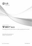
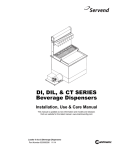
Operation Manual and Parts Directory
LC84
Conquest Post-Mix Remote Soda Line Chiller
Glastender, Inc. · 5400 North Michigan Road · Saginaw, MI · 48604-9780
800.748.0423 · 989.752.4275 · Fax 800.838.0888 / 989.752.4444 · www.glastender.com
Rev. 06-11-15
© 2006 Glastender, Inc.
Index
INSPECTION AND LOCATION
Inspection Upon Arrival..................................................... 1
Location of Remote Cooler................................................ 1
Removing the Top Cover................................................... 1
INSTALLATION
Electrical Hook-Up............................................................ 2
Refrigeration Start-Up....................................................... 2
Connection of Water Supply.............................................. 2
Connection of “Product Out” Lines................................... 2
Connection of “Product In” Lines..................................... 2
Connection of CO2 Cylinders........................................... 3
Start-Up of Dispensing System......................................... 3
Insulated Conduit............................................................... 3
CLEANING AND MAINTENANCE
Water Level........................................................................ 4
Cleaning Hints................................................................... 4
Water Bath Cleaning and Maintenance............................. 4
Sanitizing Water Circuits................................................... 4
Sanitizing Syrup Circuits................................................... 4
Preventative Maintenance Schedule.................................. 5
TROUBLE SHOOTING PROCEDURES
Poor Carbonation............................................................... 6
Bad Taste in Beverage....................................................... 6
Noisy Carbonator Pump..................................................... 6
Compressor Will Not Run.................................................. 6
Compressor Runs But Stops.............................................. 6
Compressor Runs But Will Not Cool................................ 6
Carbonator Pump Motor Will Not Run............................. 6
Carbonator Pump Motor Will Not Stop............................. 6
Carbonator Pump Running In Wrong Direction................ 6
Circulating Pump Motor Will Not Run............................. 6
Circulating Pump Running In Wrong Direction................ 6
Pump Leaking Water.......................................................... 6
Warm Beverage.................................................................. 6
Water Bath Freezing Completely....................................... 6
Noise In Water Bath........................................................... 6
SPECIFICATIONS...............................................................7-8
TYPICAL INSTALLATION DIAGRAMS............................ 9
WIRING DIAGRAM............................................................. 10
LC84 COMPRESSOR AND RELATED PARTS.........11 - 12
WARRANTY.......................................................................... 13
Glastender, Inc. • 5400 North Michigan Road • Saginaw, MI • 48604-9780
800.748.0423 • 989.752.4275 • Fax 800.838.0888 / 989.752.4444 • www.glastender.com
Inspection and Location
1.
INSPECTION UPON ARRIVAL
• Immediately upon receipt of the unit, make a visual inspection of the carton to determine if there is evidence of damage. Following un-crating, make an inspection for signs of damage.
• If damage is found, notify the carrier immediately.
• The Transportation Company is liable for damage sustained during shipment but claims must be made with in 15 days.
2.
LOCATION
OF REMOTE COOLER
• Unit can be placed up to 150 ft. (45.7m.) from the dispens-
ing station. The low profile design allows the unit to be located under counter.
• If unit is installed on the floor:
a) the cabinet must be sealed to the floor with an NSF listed silicon RTV applied around the entire periph-
ery of the cabinet (see fig.1)
b)optional 6” legs must be installed to the cabinet bottom.
CABINET BOTTOM
RTV
RTV TO FORM A FILL
ET WHEN
CABINET PLACED UP
RIGHT
Fig. 1 Sealing Cabinet with RTV
• If unit is installed on a countertop or shelf:
a)the cabinet must be sealed to the countertop or shelf with an NSF listed silicon RTV applied around the entire periphery of the cabinet. (see fig.1)
b) optional 4” legs must be installed to the cabinet bottom.
• Any location must have the ability to support the operat-
ing weight of the unit. (261 lbs./118 kg.)
• Avoid obstructions to the air intake and exhaust sections of the unit.
• Minimum clearance between the top, front, and back of unit
and any obstruction is 12 in. (30.5cm.)
• Proper unrestricted airflow is essential.
• After the unit is in place, check to be sure it is level.
3.
REMOVING THE FRONT COVER
• Remove the three-(3) screws in front of the unit, and two-
(2) screws on top rear. (see fig.2)
Fig. 2 Removal of Front Cover
• Lift cover up to disengage from rear of the unit, then pull forward.
• Do not remove the screws along the sides or back.
1
Glastender, Inc. • 5400 North Michigan Road • Saginaw, MI • 48604-9780
800.748.0423 • 989.752.4275 • Fax 800.838.0888 / 989.752.4444 • www.glastender.com
Installation
1. ELECTRICAL HOOKUP
• Unit is supplied with a 20-amp line cord on the left rear of the unit.
NOTE: THIS UNIT REQUIRES 20
AMP CIRCUIT PROTECTION
• Connect syrup out lines (3/8” male barb) to a color- coded conduit. (Note which numbered line goes to which colored tube.) (see fig. 4)
• Secure connections with proper sized “O” clamps.
• Connect the recirculating soda line (3/8” tubing) to
the barbed fitting coming from the insulated pump.
(see fig. 4) Labeled “Soda Return”.
• The main supply cord comes off the control box, located
on the pump deck. The refrigeration power cord plugs
• Connect the other 3/8” line to the barbed fitting on the
into the back of the control box, also located on the pump soda coil. Labeled “Soda Out”.
deck.
2. REFRIGERATION START-UP
• Remove top cover. Locate the black plastic water bath
fill-plug and remove it. (see fig.3)
• Fill the unit with clean water until water begins to come out of the overflow tube.
• Plug in main power cord and the condenser fan and
compressor should start. (see fig. 3) If not, refer to
“TROUBLESHOOTING PROCEDURES”.
Fig. 3
Control Box Switches
Filling the
Water Bath
NOTE: A small amount of water will flow out of the over
flow tube until the ice is fully formed.
3.
CONNECTION OF WATER SUPPLY
Syrup and Soda Lines
Water-in Tube
• Glastender, Inc. recommends that a 1/2” water line with
shut-off valve be installed within 10-ft. (3 M.) of the unit.
Incoming water pressure is not to be less that 20 P.S.I.
NOTE: If water pressure exceeds 60 P.S.I. or severely fluctuates, a water pressure regulator is required ahead of the
brass pump to avoid flooding the Carbonator. This regulator
is not supplied as standard equipment
• Before connecting water supply, drain approximately
two gallons of water from supply to flush out foreign
matter.
• It is recommended that a water filtering systems be
installed to reduce “off” tastes and odors. Use a system
that can filter out dirt particles 1 micron and larger.
Also amoebic and giardial cysts, asbestos fibers and
other similar contaminants.
• Connect water supply to the 3/8” barb of the fitting of
the water-in tube. (see fig. 4, Labeled Water Supply)
• Secure with proper sized “O” clamps.
4.
CONNECTION OF “PRODUCT OUT” LINES
• Install the insulated bundled tubes on the 3/8” barb fittings.
Fig. 4 Connection of Water in Line
5.
CONNECTION OF “PRODUCT IN” LINES
• Install the 1/4” I.D. braided tubing from the syrup
supply location to the 1/4” male barb connections on the unit. Use tie wraps to neatly bundle supply lines.
• Secure lines to product coils with “O” clamps.
Glastender, Inc. • 5400 North Michigan Road • Saginaw, MI • 48604-9780
800.748.0423 • 989.752.4275 • Fax 800.838.0888 / 989.752.4444 • www.glastender.com
2
Installation
6.
CONNECTION OF CO2 CYLINDERS
• Mount the regulator assembly conveniently near the product supply and CO2 cylinder.
• Use either a regulator with a wall mounting bracket or mount directly to the cylinder.
• An extension tube is mounted to the carbonator tank with 1/4” barb fitting for ease of connection. Measure and cut a length of 1/4” I.D. braided flexible tubing to go from the CO2 regulator to the carbonator extension tube (labeled C02). (Leave enough line to go through the top cover of the unit.)
• Measure and cut 1/4” I.D. braided flexible tubing for each syrup gas line. Connect one end to the regulator manifold and the other end to syrup supply.
7.
START-UP OF DISPENSING SYSTEM
• Open main water supply valve.
Purge air from carbonator by lifting relief valve.
• Turn on “CARB” switch. (see fig. 3)
• Close all CO2 regulators.
• Open the valve on the CO2 cylinder. (The high pres
sure gauge will read about 800 P.S.I.)
• Adjust the carbonator regulator to 100 P.S.I.
• Operate a valve until carbonated water flows freely (without spurting).
• Adjust the syrup regulator to 50 P.S.I.
• Adjust diet syrup regulator (if used) to 12 P.S.I.
• Check all connections for leaks.
• Insulate and tape all exposed refrigerated conduit lines.
• After refrigeration systems has cycled off once, turn on recirculating switch. (Full ice bank is required to cool
tower.) Replace top cover.
• Follow standard brixing procedures.
3
Fig. 5 GLASTENDER TEMPLOCK Insulated Conduit
8.
INSULATED CONDUIT (Figure 5)
• The GLASTENDER TEMPLOCK insulated tube con-
duit is recommended for this remote Post-Mix applica-
tion. This manufactured conduit maximizes the cooling performance of the system.
• Conduit may be run under floors, over ceilings, under
the counter or bar, and will not kink in an 18-inch radius
around a corner.
• When conduit is to be run across ceilings or under coun
ters, always place conduit straps every 3-ft. to prevent
sagging.
• On runs through ceilings that are also used for air con-
ditioning return ducts, check local fire codes. They may require that the conduit be covered with a fire rated metal flex duct.
• It is recommended that the chase protrude above the floor level a minimum of 2 inches and should be sealed off once the installation has been completed. By sealing off the floor chase, you eliminate the possibility of for-
eign matter being spilled into it, which could permeate the conduit.
Glastender, Inc. • 5400 North Michigan Road • Saginaw, MI • 48604-9780
800.748.0423 • 989.752.4275 • Fax 800.838.0888 / 989.752.4444 • www.glastender.com
Cleaning and Maintenance
1. WATER LEVEL
• Due to evaporation, it is necessary to periodically check the water level of the bath. Add water as required.
• A low water level results in noisy operation and reduces cooling capacity.
2.
CLEANING HINTS
• Clean external cabinetry with mild soap and warm water.
• Do not use strong bleaches or detergents.
• Do not use steel wool, scouring pads, abrasives, etc.
• Do not use hot water; this may damage certain materials.
• The refrigeration condenser should be cleaned with a soft bristle brush or a vacuum cleaner.
3.WATER
BATH CLEANING AND DRAINING
• Disconnect main power.
• Remove top cover.
• Remove drain tube holding clamps and drain water from bath.
Note: Because the water bath tank is well insulated, it may
take hours for the ice to melt naturally. The ice can be melted
faster by refilling the tank with warm water.
• Disconnect the refrigeration deck power cord from the control box.
• Remove six (6) hold-down screws (shipping screws).
• Clean coils and inside of tank with soap or detergent and
rinse with water.
• Replace motor and pump deck.
• Replace refrigeration deck. Plug cord from refrigeration
deck back into control box.
• Replace rear panel.
• Replace drain tube in holding clamps making sure hole in
plastic/copper elbow is on top.
• Refill tank until water comes out of the overflow tube.
• Replace top cover.
4. SANITIZING WATER CIRCUITS
• Turn on water and flush at least five gallons through entire
system (plain and carbonated water circuits).
• Fill a five-gallon pressure tank with a mild cleaning solution
(1 lb. baking soda to 5 gallon of water).
• Flush lines with this cleaning solution by connecting soda
water line to outlet of tank (baking soda) and pressurize with
CO2. • Fill a five-gallon pressure tank with a chlorine solution
(1-½ oz. Clorox to 5 gallons of water).
• Flush lines with this chlorine solution to prevent mold and
bacteria growth by connecting soda water line to outlet of
tank (chlorine) and pressurizing with CO2 Connect water
lines to the dispenser.
• Flush entire system with potable water (suitable for drink-
• After ice has melted, lift out the refrigeration deck by itsing) to remove all trace of chlorine solution.
handles.
• Clean the evaporator coil with soap or detergent using a soft brush. Rinse with clean water.
• Remove the rear panel for easier access to this base. This is accomplished by removing 2 screws on each side and 4 screws across the back.
• Make sure CO2, water and syrup supply are all shut off.
• Depressurize the carbonator by lifting its relief valve.
• Remove five (5) hold-down screws (shipping screws).
• Lift out motor and pump deck.
5.
SANITIZING SYRUP CIRCUITS
• Uncouple syrup line from syrup container.
• Connect syrup line to tank filled with potable water (suitable for drinking). Pressurize at least 2 gallons of water
through each syrup circuit.
• Connect 5-gallon pressure tank containing soda solution (1
lb. Baking soda to 5 gallons of water) and flush through
syrup circuits.
• Repeat above procedure using chlorine solution (1-½ oz. Clorox
to 5 gallons of water) to prevent mold and bacteria growth.
• Repeat above procedure using potable water (suitable for
drinking) to flush system of all trace of chlorine solution.
Glastender, Inc. • 5400 North Michigan Road • Saginaw, MI • 48604-9780
800.748.0423 • 989.752.4275 • Fax 800.838.0888 / 989.752.4444 • www.glastender.com
4
Cleaning and Maintenance
PREVENTIVE MAINTENANCE SCHEDULE
DailySyrup TankWhen Cleaning Tanks
ConnectorsRinse Both Quick Connects
In Clean Warm Water.
DailyDispensingWash Nozzle And Diffuser
ValvesIn Warm Soapy Water And
Rinse In Warm Water
DailyDispensing Wash With Mild Detergent
TowersAnd Warm Water, Then
Wipe Dry. Flush Drain
With Warm Water
Twice WeeklyDispensingFollow Standard Brixing
Tower BrixInstructions
Check
Weekly
Remote Cooler
Wash With Mild Detergent
And Wipe Dry
WeeklySystemReview Pressure Gauges
PressuresFor Proper Settings
MonthlyRemote CoolerClean Condenser With A
Air CooledSoft Bristled Brush Or
CondenserVacuum Cleaner
Every 6 Months
Syrup Lines
Follow “SANITIZING SYRUP CIRCUITS” Instructions
Every 6 Months
Water Lines
Follow “SANITIZING WATER CIRCUITS”
Every 6 Months
Water Bath
Follow “WATER BATH
DRAINING AND CLEANING”
Instructions
Every 6 Months
Lubrication
Lubricate Circulating And
Carbonator Pump Coupling With 3-5 Drops Of SAE 20 Non-Detergent Oil
5
Glastender, Inc. • 5400 North Michigan Road • Saginaw, MI • 48604-9780
800.748.0423 • 989.752.4275 • Fax 800.838.0888 / 989.752.4444 • www.glastender.com
Trouble Shooting Procedures
1.
POOR CARBONATION
• Verify that switch is in “ON” position.
Temperature of the soda water in cup affects the amount • Check all wire junctions and tighten any loose connections.
of carbonation retained in water. If drink is above 40
• Replace ice-bank control.
degrees F. only 92% is retained. When taking drink
temperature, always dispense at least 16 ounces of
product to get a true reading.
6.
COMPRESSOR RUNS BUT STOPS
Flooded carbonator caused by water being supplied at a • Air-cooled: Clean condenser
higher pressure than the CO2 pressure. Check pressure regulator system. Make sure it is at least 35 P.S.I. lower• Water-cooled: Verify adequate water supply.
than CO2 pressure. The CO2 pressure should be 100
P.S.I.G.
7. COMPRESSOR RUNS-WILL NOT COOL
Any substance with an oil base will knock out carbona- • Check for refrigerant leaks
tion. Make sure no pipe dope or compound is on any
fitting. Always use teflon tape.
• Replace condenser.
Ice that is super cold will cause foaming problems and 8. CARBONATOR PUMP MOTOR WILL a loss of carbonation. Bring ice to melt temperature (28
degrees) before using.
NOT RUN
• Check fuse and supply switch. Make sure switch is on.
• Make sure faucet and nozzle are clean.
•
•
•
•
5.
COMPRESSOR WILL NOT RUN
2.
BAD TASTE IN BEVERAGE • Pipe compound or pipe dope can impart a taste to the •
water. Remove piping and clean joints. Replace piping
using only teflon tape.
•
• Carbon dioxide (CO2) gas is odorless, colorless, and tasteless. If CO2 gas contains any oil or sludge from fill-
ing tanks, a bad taste could result.
• Soda water reacts to brass or copper and becomes toxic. •
Remove any brass or copper object coming in contact
with soda water. Replace with polyethylene or stainless •
steel.
3. NOISY CARBONATOR PUMP
Check switch on beverage system by disconnecting power supply. Remove 2 wires from switch. With switch in “ON”
Remove 2 wires from switch. With switch in “ON” position,
connect continuity tester to both terminals of switch. If no
continuity, replace switch.
Check circulating pump to be sure it turns freely by hand. If not, replace it.
With pump removed and proper voltage supplied to the motor and it fails to run, it is defective and must be
replaced.
• Check to see that filter and/or strainer are not clogged, 9. PUMP LEAKING WATER
and water valve to unit is wires from switch. With
• Check for worn seal. If so, replace pump
switch in “ON” fully opened.
• Incoming water supply to unit should be 3/8” I.D. • Pump must be insulated properly to prevent condensation.
minimums.
10. WARM BEVERAGE
• Be sure pump and pump motor are properly aligned and
• Check for defective circulating pump. If so, replace it.
the clamp is tight.
• Check water bath temperature (30º +/-2) and level.
• Broken vanes in pump requiring pump replacement.
• Clean condensor coil at air intake.
4.
NOISY RECIRCULATING PUMP
• Check for restrictions in recirculating lines.
11.
WATER
IN BATH FREEZING COMPLETELY
• Be sure pump and pump motor are properly aligned and • Ice-bank control defective and must is be replaced.
clamp is tight.
• Broken vanes in pump requiring pump replacement.
12.
NOISE IN WATER BATH
• Water level in bath low. Refill to proper level.
Glastender, Inc. • 5400 North Michigan Road • Saginaw, MI • 48604-9780
800.748.0423 • 989.752.4275 • Fax 800.838.0888 / 989.752.4444 • www.glastender.com
6
Specifications
1/3 HP Post-Mix Remote
LC84 CONQUEST
Standard Features
22.25”
LC84 CONQUEST
• Modular lift-out refrigeration system for easy in-field service
• High capacity refrigeration and recirculation for high volume and remote long distance installations
• CFC-free R134a refrigerant
• Light-weight, roto-molded water bath with drain
• Up to six (6) syrup circuits with recirculating soda and water
• Polyurethane foamed-in-place insulation
• Self-contained carbonation system
NOTE: Clearance of 12”
required around unit for
maintenance and air flow.
16
.5
0”
5”
26.7
Specifications
Dimensions
• Height - 22.25” (56.5 cm)
• Width - 26.75” (67.9 cm)
• Depth - 16.50” (41.9 cm)
Circuits
• Six (6) syrup, plus soda and water
Electrical
• 115V/60 Hz/16.0 Amps
• 230V/50 Hz/8.0 Amps
• 20 amp circuit required
• Includes a 6-foot grounded cord
Refrigeration
• 1/3 HP, R134a refrigerant
Water Bath
• Roto-molded polyethylene
Insulation
• Polyurethane foamed-in-place
7
Ice Bank
• 35 lbs (15.9 kg)
Maximum Draw Rate
• 6 oz drinks - 460 at 4 per min
• 12 oz drinks - 253 at 2 per minute
• Based on a 40ºF (4.4ºC) or below dispensed drink, ambient and incoming syrup and water at a tem-
perature of 75ºF (23ºC)
Recovery
• 3 six ounce drinks per minute
Pull Down
• 6.9 hours operational
Maximum Distance to Dispensers
• 150 ft (46 m)
Carbonator
• Integral cold carbonator
Carbonator Pump
• 100 gph (378 lph)
Carbonator Motor
• 1/3 HP (.25 kW)
Circulating Pump
• 70 gph (265 lph)
Circulating Motor
• 1/3 HP (.25 kW)
Shipping Weight
• 143 lbs (65 kg)
Operating Weight
• 261 lbs (119 kg)
Shipping Cube
• 9.8 cu ft (.278 cu m)
Options
• 4” Adjustable legs (up to 5-1/2”)
Glastender, Inc. • 5400 North Michigan Road • Saginaw, MI • 48604-9780
800.748.0423 • 989.752.4275 • Fax 800.838.0888 / 989.752.4444 • www.glastender.com
Specifications
Removable
Cover-Pull
towards you
to remove
Air Intake
26.75"
ISOMETRIC
Screws to
remove cover
On/Off
Switch
FRONT
Exhaust
16.50"
14.375"
TOP
Removable
Cover
10.125"
12.125"
REAR
1.625"
Exhaust
note: compressor failure due to restriction
or blockage of air flow will void warranty.
allow 20" clearance above unit to service compressor
Exhaust
Compressor Area
(Under cover)
Exhaust
Air Intake
22.25"
SIDE
NOTE: Air flow & proper ventilation required for compressor
12” gap on sides for ventilation & to remove cover, 3” gap in rear for recirculation line hook-up, and 20” gap on top for ventilation and servicing.
Top, front, & sides are one piece and are
removable for servicing the compressor.
Electrical
Cord & Plug
8
Glastender, Inc. • 5400 North Michigan Road • Saginaw, MI • 48604-9780
800.748.0423 • 989.752.4275 • Fax 800.838.0888 / 989.752.4444 • www.glastender.com
Typical Installation Diagrams
Typical Installation - Using bag-in-box syrup system
Typical Installation - Using product tank syrup system
9
Glastender, Inc. • 5400 North Michigan Road • Saginaw, MI • 48604-9780
800.748.0423 • 989.752.4275 • Fax 800.838.0888 / 989.752.4444 • www.glastender.com
Wiring Diagram
115v/60hz 20 amp RECEPTICAL REQUIRED
GREEN
BLACK
AGITATOR MOTOR
TEMPERATURE CONTROL
M
BLACK
WHITE
CONDENSER FAN
WHITE
RECEPTICAL
WHITE
BLACK
RECIRC SWITCH
WHITE
TERMINAL BLOCK
OVERLOAD
COMMON
BLACK
CARBONATOR
TANK
SWITCH
BLACK
GREEN
CARBONATOR
SWITCH
M
RELAY STARTER
M
M
CARBONATOR
MOTOR
RECIRC MOTOR
RUN START
COMPRESSOR
Glastender, Inc. • 5400 North Michigan Road • Saginaw, MI • 48604-9780
800.748.0423 • 989.752.4275 • Fax 800.838.0888 / 989.752.4444 • www.glastender.com
10
LC84 Compressor and Related Parts
2
3
7
6
1
9
4
5
8
11
10
12
13
14
17
15
16
20
18
21
11
19
Glastender, Inc. • 5400 North Michigan Road • Saginaw, MI • 48604-9780
800.748.0423 • 989.752.4275 • Fax 800.838.0888 / 989.752.4444 • www.glastender.com
LC84 Compressor and Related Parts
1.
2.
3.
4.
5.
6.
7.
8.
9.
10.
11.
12.
13.
14.
15.
16.
17.
18.
19.
20.
21.
Part No.
Old Part No.
Description
09000416
09000299
06001439
09000291
06001313
09000340
09000257
09000482
06001595
09000261
09000412
09000479
09000480
09000481
09000338
09000336
09000463
09000327
09000328
09000304
09000410
09000395
09000293
06001412
06001409
09000436
GT-037436
GT-032805
GT-035014
GT-032598
GT-031400
GT-035119
GT-006552
GT-006554
GT-031404
GT-037112
GT-034114
GT-031211
GT-032210
GT-035116
GT-035109
GT-041306
GT-034517
GT-034518
GT-033208
GT-037110
GT-036135
GT-032615
GT-033421
GT-033304
GT-036497
Refrigeration Deck Assembly Complete
Condenser Fan Blade
1/3 HP Compressor R-134A
Evaporator coil, LC83, 84 & 85, Copper
Condensing unit power cord
Recirculating pump
Complete basket assembly
Soda circuit only, tubing coil
Insulation, pump, white, set of 2 pieces
104” exterior power cord
Carbonator tank, 115V
Relay, compressor
Compressor overload
Compressor start capacitor
Agitator motor, stainless steel shaft
Condenser fan motor
Accumulator, cap tube assembly
Soda Water pump
Water pump
Ice bank control
Main cabinet tank
Complete cover, black vinyl clad
Condenser coil
Rocker switch
Snap-in receptacle
Plug, black plastic, 1 3/4” hole
Glastender, Inc. • 5400 North Michigan Road • Saginaw, MI • 48604-9780
800.748.0423 • 989.752.4275 • Fax 800.838.0888 / 989.752.4444 • www.glastender.com
Price
$985.00
10.50
405.00
110.00
20.00
350.00
508.00
139.00
9.00
20.00
415.00
20.00
11.50
10.00
170.00
85.00
40.00
350.00
190.00
100.00
130.00
78.00
125.00
4.00
5.00
.50
12
Warranty Statement
APPLICABLE TO ALL PRODUCTS SOLD WITHIN THE UNITED STATES AND CANADA
Glastender, Inc. warrants all products to be free of defects in material and workmanship. One-year labor and parts warranty applies to
all glasswashers, self-contained refrigeration models, and BDS model
bottle disintegration units. In established areas, a start up is included
with GT-24 and GT-30 model glasswashers. Warranty is effective for
one year from the date of installation or up to 18 months from date of
factory shipment, whichever occurs sooner. Glastender, Inc. will replace
any part or assembly found defective under normal use and service.
SECOND YEAR EXTENDED PARTS & LABOR WARRANTY:
For warranty labor claims beyond 15 months from the date of factory
shipment, proof of date of installation or occupancy must be provided.
Authorization for labor must be obtained from Glastender within the
warranty period and prior to the service being performed.
EXCEPT AS PROVIDED ABOVE, GLASTENDER MAKES
NO WARRANTIES, EXPRESS OR IMPLIED, INCLUDING,
BUT NOT LIMITED TO, ANY IMPLIED WARRANTY OF
MERCHANTABILITY, FITNESS FOR A PARTICULAR PURPOSE
OR NON-INFRINGEMENT.
Labor warranty applies to the United States and Canada only.
Remote refrigeration models and beer line chillers include a one-year
parts warranty only. There is no labor warranty on these products.
Field replacement parts not covered under the original warranty include
a 90-day part warranty from the date of installation.
FOUR YEAR ADDITIONAL COMPRESSOR WARRANTY:
Glastender will warrant to the original user the compressor for all selfcontained refrigeration models for an additional four years following the
regular one-year warranty period. This plan applies to the compressor
only.
A completed warranty claim form MUST accompany all returned defective parts or assemblies. Upon request, a defective part or assembly must
be returned to Glastender, Inc., Saginaw, Michigan, with all transportation and delivery charges prepaid. Warranty repairs or replacements
will be shipped FOB factory in Saginaw, Michigan. Reimbursement for
applicable freight charges covers ground service only.
Glastender provides in-warranty repairs during a service company’s
regular working days and hours. There is no provision for payment
of a premium rate during “overtime” hours. When warranty service is
requested during other than normal working hours, the end user will be
charged the premium portion of the overtime rate.
The warranty covers substantiated travel expenses for up to 2 hours /
100 miles round trip and a maximum of $150. Any additional costs due
to installations that require extra work, time, or travel to gain access
for service are the sole responsibility of the equipment purchaser. Any
exceptions to these travel and access limitations must be pre-approved
by a factory representative.
The warranty does not cover equipment subjected to accidents, freight
damage, alterations from the original design, improper power and/or
plumbing hookups, improper chemical use, general misuse, or lack
of routine required maintenance as determined by Glastender, Inc.
Installation, normal control adjustments, general maintenance, correcting an installation error, or service calls that reveal the unit is functioning normally will not be reimbursed under warranty.
Condenser coils on self-contained refrigeration products must be
cleaned regularly. Failure to provide adequate air flow to a refrigeration
unit will void the warranty.
Glastender shall not be liable for loss of use, revenue, or profit, or for
any other indirect, incidental, special, or consequential damage including, but not limited to, product spoilage or loss.
This warranty is conditioned upon Glastender receiving notice of any
defect subject to this warranty within sixty (60) days of its discovery
by the end user or dealer. All products are warranted only for the initial
place of installation. Removal of a product automatically terminates
this warranty.
13
Glastender’s one-year parts and labor warranty on self-contained refrigeration units, excluding beer line chillers, can be extended to two years
with the purchase of a two year parts and labor warranty. Specify part
number EWR2 ($150 net price) when ordering.
EXPORT WARRANTY - One year parts only.
EXCLUSION OF WARRANTIES
LIMITATION
OF
REMEDIES
AND
DAMAGES
If Buyer makes a valid and timely claim as outlined above, Glastender’s
liability and Buyer’s remedies under this agreement will be limited solely
to labor charges authorized and/or replacement or credit, at Glastender’s
option, with respect to Products returned at Buyer’s expense within thirty (30) days after warranty repair. GLASTENDER’S LIABILITY WILL
IN NO EVENT BE GREATER IN AMOUNT THAN THE PURCHASE
PRICE OF THE RETURNED PRODUCTS. GLASTENDER
WILL NOT BE LIABLE UNDER ANY CIRCUMSTANCE FOR
CONSEQUENTIAL OR INCIDENTAL DAMAGES, INCLUDING,
BUT NOT LIMITED TO, LABOR COSTS EXCEPT AS COVERED
UNDER OUR WARRANTY, LOST PROFITS OR THE LOSS OF
PERISHABLE PRODUCTS RESULTING FROM THE USE OF OR
INABILITY TO USE OUR PRODUCTS OR FROM OUR PRODUCTS’
INCORPORATION INTO OR BECOMING A COMPONENT OF
ANY OTHER PRODUCT. NEITHER PARTY WILL HAVE ANY
NEGLIGENCE OR OTHER TORT LIABILITY TO THE OTHER, OR
TO ANY THIRD PARTY, ARISING FROM ANY BREACH OF THIS
AGREEMENT.
GOVERNING LAW - JURISDICTION
The terms and conditions of an order are to be governed and construed
according to the laws of the State of Michigan, without regard to conflict
of laws principles. Buyer hereby consents to the jurisdiction and venue
of the courts located in Saginaw County, Michigan.
No representative, distributor, dealer, or any other person is authorized
to modify this warranty. This warranty replaces all other written or
verbal warranties.
NOTE: Glastender, Inc.’s policy of constant quality improvement
means that prices, specifications, and policies are subject to change
without notice. Questions regarding this warranty should be directed to
Glastender’s Warranty Administrator.
06-11-15
IMPORTANT!!
Attention Service Companies
Please review the important warranty information on this page. If you
believe a service call should be covered by the factory, please call
the factory for authorization between 8AM and 5PM EST, Monday
through Friday.
Glastender, Inc. • 5400 North Michigan Road • Saginaw, MI • 48604-9780
800.748.0423 • 989.752.4275 • Fax 800.838.0888 / 989.752.4444 • www.glastender.com