1
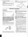
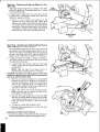
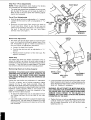
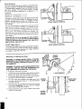
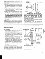
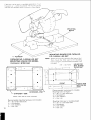
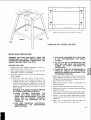
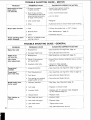
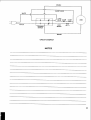
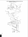
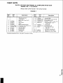
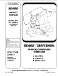
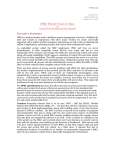
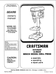
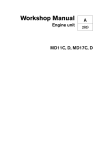
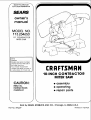
f'_ Save ThisManual
For Future Reference
owner's
manual
MODEL NO.
113.234650
I 0" CONTRACTOR
MITER SAW
Serial
Number
Model and serial numbers
may be found at the side of
the miler saw arm.
You should record both
model and serial number
in
a safe place for future use.
CRRFTSMRN
10-1NCH CONTRACTOR
MITER SAW
CAUTION:
• assembly
• operating
• repair parts
READ ALL
INSTRUCTIONS
CAREFULLY
J
Sold by SEARS, ROEBUCK AND CO., Chicago,
Part No. SP5229
J
IL 60684
U.S.A.
Printed
in Taiwan.
FULL ONE YEAR WARRANTY
ON CRAFTSMAN
MITER SAW
If within one year from the date of purchase, this Craftsman Miter Saw fails due to a defect
in material or workmanship, Sears will repair it, free of charge.
WARRANTY SERVICE iS AVAILABLE BY SIMPLY CONTACTING THE NEAREST SEARS SERVICE CENTER/DEPARTMENT THROUGHOUT THE UNITED STATES.
This warranty applies only while this product is used in the United States.
This warranty gives you specific legal rights, and you may also have other rights which
vary from state to state.
SEARS, ROEBUCK AND CO., Dept. 698/731A, Sears Tower, Chicago, IL 60684
GENERAL SAFETY INSTRUCTIONS
1. KNOW YOUR POWER TOOL
Read and understand the owner's manual and
labels affixed to the tool. Learn its application and
limitations as well as the specific potential hazards
peculiar to this tool.
2. This tool is DOUBLE INSULATED to give you
added protection. Double insulation does not take
the place of normal safety precautions when
operating this tool. When servicing this double insulated tool, use only identical parts.
3. KEEP GUARDS IN PLACE
In working order, and in proper adjustment and
alignment.
4. REMOVE ADJUSTING KEYS AND WRENCHES
Form habit of checking to see that keys and adjusting wrenches are removed from tool before turning
it on.
5. KEEP WORK AREA CLEAN
Cluttered areas and benches invite accidents. Floor
must not be slippery due to wax or sawdust.
6. AVOID DANGEROUS ENVIRONMENT
Don't use power tools in damp or wet locations or
expose them to rain. Keep work area well lighted.
Provide adequate surrounding work space.
7. KEEP CHILDREN AWAY
All visitors should be kept a safe distance from
work area.
8. MAKE WORKSHOP CHILD-PROOF
With padlocks, master switches, by removing starter keys, or storing tools where children can't get
them.
9. DON'T FORCE TOOL
It wil! do the job better and safer at the rate for
which it was designed.
10, USE RIGHTTOOL
Don't force tools or attachment to do a job it was
not designed for.
11. WEAR PROPER APPAREL
Do not wear loose clothing, gloves, neckties, or
jewelry (rings, wrist watches) to get caught in moving parts. NONSLIP footwear is recommended.
Wear protective hair covering to contain long hair.
Roll long sleeves above the elbow.
FOR POWER TOOLS
12. USE SAFETY GOGGLES (HEAD PROTECTION)
Wear safety goggles (must comply with ANSI
Z87.1) at all times. Everyday eyeglassess are not
safety glasses. They only have impact resistant
lenses. Also, use face or dust mask if cutting operation is dusty, and ear protectors (plugs or muffs)
during extended periods of operation.
13. SECURE WORK
Use clamps or a vise to hold work when practical.
It frees both hands to operate tool.
14. DON'T OVERREACH
Keep proper footing and balance at all times.
15. MAINTAIN TOOLS WITH CARE
Keep tools sharp and clean for best and safest
performance. Follow instructions for lubricating and
changing accessories.
16. DISCONNECT TOOLS
Before servicing; when changing accessories such
as blades, bits. cutters, etc.
17. AVOID ACCIDENTAL STARTING
Make sure switch is in "OFF" position before plugging in.
18. USE RECOMMENDED ACCESSORIES
Consult the owner's manual for recommended accessories. Follow the instructions that accompany
the accessories. The use of improper accessories
may cause hazards.
19. NEVER STAND ON TOOL OR ITS STAND
Serious injury could occur if the tool is tipped or if
the cutting tool is accidentally contacted. Do not
store materials above or near the tool such that it
_s necessary to stand on the tool or its stand to
reach them.
20. CHECK DAMAGED PARTS
Before further use of the tool, a guard or other part
that is damaged should be carefully checked to
ensure that it will operate properly and perform its
intended function. Check for alignment of moving
parts, binding or moving parts, breakage of parts,
mounting, and any other conditions that may affect
its operation. A guard or other part that is damaged
should be properly repaired or replaced.
21. NEVER LEAVETOOL RUNNING UNATTENDED
Turn power off. Don't leave tool until it comes to a
complete stop.
additional safety instructions for miter saw
Safety is a combination of common sense, staying alert
and knowing how your miter saw works.
BEFORE
USING THE SAW:
WARNING: TO AVOID MISTAKES THAT COULD
CAUSE SERIOUS, PERMANENT INJURY, DO NOT
PLUG THE SAW IN UNTIL THE FOLLOWING STEPS
HAVE BEEN SATISFACTORILY COMPLETED.
power tool can result in foreign objects being
thrown into the eyes, which can result in permanent eye damage. Safety goggles are available
at Sears retail catalog stores. Use of glasses or
use of goggles not in compliance with ANSI Z87.t
could result in severe injury from breakage of the
eye protection.
WEAR
YOUR
1. Assembly and alignment.
2. Learn the function and proper use of:
a. The on-off switch.
b. The upper and lower blade guards.
c. The arbor lock and handle latch.
d. The bevel clamp, fence clamps, and miter lock
handle.
3. Read and understand all safety instructions
operating procedures throughout the manual.
and
4. Read the following label on the miter saw:
WHEN INSTALLING
OR MOVINGTHE
b. For dusty operations,
with safety goggles.
along
c. To avoid injury from jams, slips or thrown pieces:
t. Choose the right 10-inch diameter blade for
the material and the type of cutting you plan
to do. Use this miter saw to cut only wood,
wood-like
products
or soft
metals
like
aluminum.
Other materials may shatter, grab
at the blade, or create other dangers.
SAW:
1. To avoid injury from unexpected saw movement:
a. Place the saw on a firm level surface where there
is plenty of room for handling and properly supporting the workpiece.
b. Support the saw so the table is level and the saw
does not rock.
2, Make sure the direction of rotation arrow on
the blade matches the direction arrow on the
saw. The blade teeth should always point
downward
at the front of the saw.
3.
c. Bolt or clamp the saw to its support.
2. Before moving the saw, lock the miter, bevel and
power-head positions. Unplug electric cord.
3. To avoid back injury, get help when you need to lift
the saw more than 10 inches. Hold the tool close to
your body. Bend your knees so you can lift with your
legs, not your back. Lift by using the hand-hold areas
at "the bottom of the base. Never carry the tool by
the cord or power head handle. Damage to insulation
could cause an electric shock. Damage to wire connections could cause a fire.
4. Place the saw so others will stay out from behind it.
Thrown debris could injure people in its path.
EACH USE:
Make sure the blade is sharp, undamaged
and properly aligned. With the saw unplugged,
push the power-head all the way down. Hand
spin the blade and check for clearace. Tilt the
power-head
to 45 degree bevel and repeat
the check. If the blade hits anything,
make
the adjustments
shown in the Maintaining
Maximum Cutting Capacity section.
4. Make sure the blade
clean,
5. Make sure the collars'
ing toward the blade.
and arbor
recessed
6. Make sure the recessed
side
washer
(just under the arbor
faces the collar.
collars
are
sides are facof the blade
screw head)
7. Using l_._-inch box end wrench, make sure the
arbor cap screw retaining the blade collars is
firmly hand tightened
8
BEFORE
wear a face shield
Make sure all clamps
there is no excessive
9. Never
and locks are tight and
play in any parts.
cut FREEHAND:
1. Inspect your saw. If any part of this miter saw is
missing, or bent, or has failed in any way, or any
electrical parts don't work properly, turn the saw off
and unplug the saw. Replace damaged, missing, or
failed parts before using the saw again.
2. Plan Your Work to protect your eyes, hands,
face, ears.
a
Brace your workpiece
solidly against the
fence and table top so it wil! not rock or
twist during the cut. Make sure no debris
is caught beneath the workpiece.
b
Make sure no gaps between
the workpiece, fence and table will let the workpiece
shift after it is cut in two.
a. Wear safety goggles (not glasses) that comply
with ANSI Z87.1 (shown on package). Using any
c
Use jigs, fixtures or a different
stable workpieces.
tool for un3
10. Never cut more than one workpiece at a time,
11. Make sure the cut off piece can move sideways after it's cut off, Otherwise, it could
get wedged against the blade and thrown
violently.
12. Use extra caution with large, very small or
awkward workpieces:
a. Use extra supports (tables, saw horses,
block& etc.) for any workpieces large
enough to tip when not held down to the
table top.
b. Do not use this saw to cut pieces too
small to let you easily hold the work while
you keep the thumb side of your index
(pointer) finger against the outside edge
of the fence.
c. When cutting irregularly shaped workpieces, plan your work so it will not slip
and pinch the blade. A piece of molding,
for example, must lie flat or be held by a
fixture or jig that will not let it twist, rock
or slip while being cut.
d. Properly support round material such as
dowel rods, or tubing. They have a tendency to roll while being cut. causing the
blade to "bite." To avoid this, always use
a fixture designed to properly hold your
work piece.
13, Make sure there are no nails or foreign objects in the part of the workpiece to be cut.
14. Make sure bystanders are clear of the tool
and workpiece Keep them clear of the area
behind the saw where debris wilt be thrown.
15. Never turn your miter saw "ON" before clearing everything except the workpiece and
related support devices off the table.
d. To avoid risk of hearing damage, wear ear plugs
or muffs during extended periods of operation.
e. To avoid being suddenly pulled into the blade:
1. Do not wear gloves.
2. Remove all jewelry and loose clothing.
3. Tie back long hair.
f. To avoid injury from accidental starting, always
unplug saw before disconnecting the guard, installing or removing any blade, accessory or
attachment, or making any adjustments.
g, To avoid an electrical shock, make sure your
fingers do not touch the metal prongs on the plug
when inserting or remowng the ptug to or from
a live outlet.
h. Never put lubricants on the blade while it's
spinning,
i. To avoid burns or other fire damage, never use
the saw near flammable liquids, vapors or gases.
j. To avoid injury from unsafe accessories, use only
accessories shown on the recommended accessories list in this manual.
WHENEVER
SAW IS RUNNING:
WARNING: DON'T ALLOW FAMILIARITY (GAINED
FROM FREQUENT USE OF YOUR MITER SAW) TO
CAUSE A CARELESS MISTAKE. ALWAYS REMEM BER THAT A CARELESS FRACTION OF A SECOND IS ENOUGH TO CAUSE A SEVERE INJURY.
1. Before actually cutting with the saw, let it run for a
while. If your saw makes an unfamiliar noise or if it
vibrates excessively, stop immediately. Turn the saw
off. Unplug the saw. Do not restart until finding and
correcting the problem.
2, Never confine the piece being cut off. Never hold it,
ctamp it, touch it, or use length stops against it. It
must be free to move sideways If confined, it could
get wedged against the blade and thrown violently.
3. Avoid awkward hand positions where a sudden slip
could cause a hand to move into the blade.
4. Let the blade reach full speed before cutting.
5. Feed the saw into the workpiece only fast enough
to let the blade cut without bogging down or binding.
6. Before freeing jammed material, release switch and
unplug the saw. Wait for all moving parts to stop,
7. After finishing a cut. keep holding the power-head
down, release the switch, and wait for all moving
parts to stop before moving your hands.
4. Roll long sleeves above the elbow.
glossary of terms for woodworking
Arbor
The shaft on which a cutting tool is mounted
Bevel Cut
An angle cutting operation made through the face of
the work piece.
Compound Cut
A simultaneous bevel and miter cutting operation.
Crosscut
A cutting operation made across the width of the workpiece.
Freehand
Performing a cut without the use of fence (guide), hold
down or other proper device to prevent the workpiece
from twisting during the cutting operation. Twisting of
the workpiece can cause it to be thrown.
Gum
A sticky, sap based residue from wood products.
Heel
Misalignment of the blade.
Kerr
The amount of material removed by the blade in a
through cut or the slot produced by the blade in a nonthrough or partial cut.
Miter Cut
An angle cutting operation made across the width of
the work piece.
Resin
A sticky, sap based substance that has hardened.
Revolutions Per Minute (RPM)
The number of turns completed by a spinning object in
one minute.
Sawblade Path
The area of the workpiece or table top directly in line
with either the travel of the blade or the part of the
workpiece which will be, or has been, cut by the blade.
Set
The distance that the tip of the sawblade tooth is bent
(or set) outward from the face of the blade.
Workpiece
The item on which the cutting operation is being performed. The surfaces of a workpiece are commonly
referred to as faces, ends, and edges.
END
_=_,
€1)
LEDGE
_J
electrical connections
POWER
SUPPLY
Motor Specifications
The AC motor used in this saw is a universal, nonreversible type having the following specifications:
H.P ....................................
3
Voltage .................................
120
Amperes ................................
15
Hertz (Cycles) ............................
60
Phase ................................
Single
RPM ..................................
4900
Rotation of Shaft ....................
Clockwise
Brake .............................
Automatic
outlet without
connection.
DOUBLE
INSULATED
The miter saw is double insulated to provide a double
thickness of insulation between you and the tool's electrical system. All exposed metal parts are isolated from
the internal metal motor components
with protecting
insulation.
Your unit has a plug that looks like the one shown below.
for
maintaining
a ground
CAUTION: Double insulation
does not take the
place of normal safety precautions when operating
this tool.
DANGER: To avoid electrocution:
1. Use only identical replacement parts when servicing
a tool with double insulation. Servicing should be
performed by a qualified service technician.
2. Do not use in rain or where floor is wet.
This tool is intended for indoor residential use only.
MOTOR
WARNING: TO AVOID ELECTRICAL
HAZARDS,
FIRE HAZARDS, OR DAMAGE TO THE TOOL, USE
PROPER CIRCUIT PROTECTION. YOUR SAW IS
WIRED AT THE FACTORY FOR 120V OPERATION.
CONNECT TO A 120V, 15-AMP, BRANCH CIRCUIT
AND USE A 15-AMP TIME DELAY FUSE OR CIRCUIT
BREAKER. TO AVOID SHOCK OR FIRE, IF POWER
CORD IS WORN OR CUT, OR DAMAGED IN ANY
WAY, HAVE IT REPLACED IMMEDIATELY.
necessity
SAFETY
PROTECTION
CAUTION: To avoid motor damage, this motor
should be blown out or vacuumed frequently to
keep sawdust from interfering with normal motor
ventilation.
1. Connect this tool to a 120V, 15-amp branch circuit
with a 15-amp time delay fuse or circuit breaker.
Using the wrong size fuse can damage the motor.
2. If the motor won't start, release the trigger switch
immediately. UNPLUG THE TOOL. Check the saw
blade to make sure it turns freely. If the blade is free,
try to start the motor again. If the motor still does
not start, refer to the "MotorTrouble-Shooting Chart."
3. If the motor suddenly stalls while cutting wood, release the trigger switch, unplug the tool, and free
the blade from the wood. The motor may now be
restarted and the cut finished
4. Fuses may "blow" or circuit breakers may trip frequently if:
a. MOTOR IS OVERLOADED--Overloading
can
occur if you feed too rapidly or make too many
start/stops in a short time.
b. Voltages not more than 10% above or below the
nameplate voltage can handle normal loads. For
heavy loads, however, the voltage at motor
terminals must equal the voltage specified on
nameplate.
This power tool is equipped with a 2-conductor cord
listed by Underwriters Laboratories (UL). The plug
permits you to use any conventional 120-volt electrical
5. Most motor troubles may be traced to loose or incorrect connections, overload, tow voltage (such as
small size wire in the supply circuit) or to overly long
supply circuit wire. Always check the connections,
the load and the suppy c_rcu_t whenever
motor
doesnt work well Check wire s_zes and length with
the Wire Size Chart below
WIRE
SIZES
The use of any extension cord will cause some _oss of
power To keep this to a minimum and to prevent overheating and motor burn-out, use the table below to
determine
the minimum wire s_ze iAWG)
extension
cord
For c_rcurts ',hat are farther than 100 f6et away from
electqca
se'wce box the wire size rnust :)e increased
proportionatey
n oraer to deliver ample voltage to the
saw motor
Length of the
•Conductor
Wire Sizes Required For 120V
',American Wire Gage Number)
O-25 Ft
26-100 Ft.
Over 100 Ft
14
12
8
contents
Page
Guarantee
...............................
General Safety Instructions
for Power Tools .....
Additional
Safety Instructions
for Miter Saws ....
Glossary of Terms for Woodworking
...........
Electrical Connections
......................
Unpacking
and Preassembly
.................
Knowing Your Miter Saw ...................
UNPACKING
2
2
3
4
5
6
7
Assembly
and Alignment
...................
Mounting the Saw
........................
Basic Saw Operations
.....................
Maintenance
and Lubrication
...............
Trouble Shooting
.........................
Repair Parts .............................
9
13
15
21
22
25
AND PREASSEMBLY
WARNING: TO AVOID INJURY FROM UNEXPECTED
STARTING OR ELECTRICAL
SHOCK, DO NOT PLUG
THE POWER CORD INTO A SOURCE OF POWER
DURING UNPACKING
AND ASSEMBLY, THIS CORD
MUST REMAIN UNPLUGGED
WHENEVER
YOU ARE
WORKING
ON THE SAW.
Model 113.234650, Miter Saw is shipped complete in
one box.
WARNING: ALTHOUGH SMALL, THIS SAW IS
HEAVY. TO AVOID BACK INJURY, GET HELP
WHENEVER YOU HAVE TO LIFT THE SAW MORE
THAN 10 INCHES.
/
Page
1. Remove the miter saw from the carton
saw by the base.
by lifting the
WARNING:
IF ANY PART IS MISSING OR DAMAGED,
DO NOT PLUG THE SAW IN UNTIL THE MISSING
OR DAMAGED
PART IS CORRECTLY
REPLACED.
TO AVOID ELECTRIC
SHOCK,
USE ONLY IDENTICAL
REPLACEMENT
PARTS WHEN
SERVICING
DOUBLE
INSULATED
TOOLS.
2. Place the saw on a secure stationary
and look the saw over carefully
work surface
tools needed
Tools required for assembly and alignment:
• Medium Screwdriver
• #2 Phillips Screwdriver
• Combination Square
• '_ Box End/Open End Wrench or Socket
• 2 - ls/!6 Box End/Open End Wrenches or Adjustable
Wrenches or Socket Wrenches
• %6" Hex 't" Wrench
COMBINATION
SQUARE MUST BE TRUE
DRAW LIGHT
LINE ON BOARD
ALONG THIS EDGE-C, ,m
"_.-'"
"_)_:_
SHOULD
SQUARE
STRAIGHT EDGE OF
BOARD 314" THICK
THIS EDGE MUST BE
//PERFECTLY
STRAIGHT
BE NO GAP OR OVERLAP WHEN
IS FLIPPED OVER IN DOTTED POSITION
c
MEDIUM
SCREWDRIVER
ADJUSTABLE WRENCH
.......
_:
_
1/2"WRENCH
#2 PHILLIPS SCREWDRIVER
W16" BOX END/OPEN END
WRENCHES
iii:iIi;1111111;:]:]
COMBINATION
SQUARE
'/2" SOCKET
5,46"HEX "1.:' WRENCH
/
1%6" SOCKETS &
SOCKET WRENCHES
=A-
knowing your miter saw
WARNING LABEL
1. Warning label,
2. Handle Latch--The miter saw can be locked in the
lowered position for compact storage.
3. Fence Lock Handles--The fence has two positions
for increased crosscut capacity. The lock handles
secure the fence to the base. The saw is shipped
with the fence in the front position.
2.
HANDLE LATCH
NOTE: If the fence is being used in the rear position,
the two fence lock handles must be loosened before
changing the miter angle. Then tighten the fence handle
at the desired miter angle before starting a cut.
4. Miter Lock Handle--The miter lock handle securely
locks the miter saw at a desired miter angle. Index
points have been provided at 0, 22.5 R/L, and 45 RiL.
5. Bevel Lock Handle--The bevel lock handle locks
the miter saw at a desired bevel angle.
6. Lower Blade Guard--The blade guard helps protect
your hands from the blade in the raised position. To
avoid binding on the workpiece, it retracts as the
blade is lowered.
7,
Miter Saw Handle--The saw handle contains the
trigger switch with a lock-off button. The blade is
lowered into the workpiece by pushing down on the
handle. The saw will return to its upright position
when the handle is released.
3,
°
FENCE LOCK
HANDLE
POWER CORD
BEVEL LOCK
HANDLE
BEVEL SCALE
UPPER BLADE
GUARD
LOCK OFF
BUTTON
,
MITER SAW
HANDLE
DUST
BAG
TRIGGER
SWITCH
°
LOWER BLADE
GUARD
FENCE
,
FENCE LOCK
HANDLE
4°
MITER LOCK
HANDLE
MITER
SCALE
/
assembly and alignment
ASSEMBLY
HANDLE
LATCH
AND ALIGNMENT
\
Assembling the Lower Blade Guard
NOTE: For compact shipment the lower blade guard
has been partially disconnected.
1. The miter saw is equipped with a handle latch used
to lock the miter saw in the lowered position. To
release, push the handle down slightly and turn the
handle latch to the other side.
2, Release the handle iatch and raise the saw to its
up position.
3. Slide the lower guard assembly down until the
groove in the mounting plate rests on the front screw.
Tighten the screw with a phillips screwdriver,
4. Remove the v4.20 shoulder screw from the pivot
casting as illustrated, Attach the blade guard link to
the pivot casting with a phillips screwdriver.
NOTE: With the blade guard link attached, the guard
should raise as the blade is lowered towards the work
table and drop to cover the blade as the power head
is raised. This link helps prevent guard hangups and
1/4-20 SHOULDER
SCRE_;_,
LINK
____
PIVOT
MOUNTING
BLADE GUARD
LINK
,--.-._.--,._ PLATE -.-
p.
8.'.'
.,vo.
CASTING
Assembly and Alignment
Step
One--Blade
Square
to Table
NOTE: The miter saw was assembled,
aligned, and
inspected
before
shipment.
Alignment
should
be
checked and any adjustments
made to insure accurate
cuts.
1. Check miter lock handle setting, The miter lock handle should be at the 0° position. To reset the miter
angle, turn the miter lock handle counter clockwise
and press down the index spring.
2. Lower the blade and lock the handle latch. Use the
combination
square to check blade squareness
to
table. If the blade does not contact the full length of
the square, follow the alignment procedure.
a. Loosen bevel lock handle.
b. Grasping
metal upper guard, move the cutting
head left or right until blade makes contact with
the full length of the square.
c. Tighten
the bevel IocX handle.
3, Check the bevel indicator. If indicator needs adjustment use a phi/lips
screwdriver
and slide the
indicator to the 0° on the scale.
f
Y--" .ow .
/71
_ JBLADE
GUARD
Step Two--Checking
Table Slot
and Aligning Blade with Turn
1. The blade should look like it's parallel to the sides
of the turn table slot. The blade should be W' closer
to left side than right.
2. If blade looks parallel with turn table slot proceed
to step three. If necessary, realign blade with turn
table slot, adjust as follows.
CAP
a. Use a 5/16"hex "U' wrench to loosen (but do not
remove) the two cap screws that attach pivot
support to turn table. Move blade power-head so
it is parallel with turn table slot. Securely tighten
cap screws. Recheck blade position and readjust
if necessary. Always check blade clearance to
table when the miter saw isfully tilted to the left.
TURN TABLE
SLOT
Step Three-- Checking and Adjusting Blade Squareness to Fence (Front Fence Position)
1. To check blade squareness to fence, use a combination square. Place the square against the fence and
next to the blade as illustrated. Place the square so
the set in the teeth won't hold it from the blade. The
blade should contact the full length of the square.
2. If blade contacts full length of square, proceed to
next step. If blade is not square to the fence, follow
the alignment procedure.
a. Loosen miter lock handle a half turn. The latch
handle should still be secured with blade in lowered position.
NOTE: Take the saw off its stand, bench or
plywood base if readjustment is necessary.
CAUTION: To keep from losing control of the unit,
steady the base with one hand while loosening the
two bolt.s with the other hand.
b. With the unit securely resting on a large stable
surface, tilt the unit by lifting up on one side or
the other of the base. Loosen the two miter arm
bolts on the underside of the turn table with a
W' wrench or socket. Tilt the unit by lifting up on
one side or the other of the base.
c. Return the saw to its normal resting position.
Make sure the miter lock handle is loose but do
not release the index spring.
d. Use the miter saw handle to turn the turn table
and saw so that the blade contacts the full length
of the square, Watch out for tooth set. Turn the
miter lock handle clockwise to lock saw square
to fence.
e. Tilt saw as in Step B and tighten bolts.
f. Recheck blade squarenesss to fence and readjust if necessary.
Adjustment
of Miter Scale Indicator
1. Loosen the phillips screws that hold the indicator in
place. Reposition the indicator and retighten screw.
10
/
Step Four--Pivot
Adjustments
PIVOT BOLT
NOTE: These adjustments were made at the factory
and normally do not require readjustment.
1. The miter saw should rise completely to the up position by itself. If the saw will not raise by itself or if
there is play in the pivot joints the following adjustments are necessary.
/
/
Travel Pivot Adjustments
a. Hold the pivot bolt with an adjustable or 1_A6"wrench.
Loosen the hex lock nut with an adjustable or Is/,6"
wrench.
HEX LOCK"
NUT
b,
Recheck the saw travel. Saw should
its up travel stop. Check to see that
raise from all positions and there is no
the pivot. If saw still won't fully rise,
Service check and repair it.
rise freely to
the saw will
looseness in
have Sears
ADJUSTABLE
WRENCH
DEPTH
STOP
Bevel Pivot Adjustment
1. The miter saw should bevel easily by loosening the
bevel lock handle and tilting the power head to the
left. If movement is tight or if there is looseness in
the pivot follow the adjustment procedure.
a. Loosen the bevel lock handle.
b. Turn the hex lock nut with an adjustable or _5/1_"
wrench.
\
-
c. Recheck bevel movement of the miter saw. Readjust if necessary.
Depth Stop
The depth stop limits the blades downward travel. It
allows the blade to go below the work table enough to
maintain full cutting capacities. The depth stop positions
the blade 1/_,,from the cast iron table support. The depth
stop is factory set and should never need adjustment.
Maintaining Maximum Cutting
Capacity
WARNING: TO AVOID INJURY FROM UNEXPECTED
STARTING OR ELECTRICAL SHOCK, DO NOTPLUG
THE SAW IN. THE POWER CORD MUST REMAIN
UNPLUGGED WHENEVER YOU ARE WORKING ON
THE SAW.
Unplug the saw before any adjustment is attempted.
This too! is factory set to provide maximum cutting
capacity for the 10" saw blade provided. When the
diameter of the blade has been reduced clue to sharpening, it may be necessary to adjust depth stop to provide
maximum cutting capacity. When a new blade is installed, it is necessary to check the clearance of the
blade to the turn table structure.
1. To adjust the depth stop use an adjustable wrench
and loosen the hex nut at the rear of the miter
saw arm.
2. Use a flat blade screwdriver to adjust the depth stop
adjusting bolt. The saw blade is lowered by turning
the bolt counterclockwise and raised by turning the
bolt clockwise.
BEVEL
LOCK
7
HANDLE
HEX LOCK
NUT
ADJUSTABLE
WRENCH
3. Lower the blade into the slot of the turn table. Check
blade clearance and maximum cutting distance (distance from fence where blade enters) to front of turn
table slot. Readjust if necessary.
WARNING: DO NOT START THE MITER SAW WITHOUT CHECKING FOR INTERFERENCE BETWEEN
THE BLADE AND THE TURN TABLE STRUCTURE.
DAMAGE COULD RESULT TO THE BLADE IF IT
STRIKES THE TURN TABLE STRUCTURE DURING
OPERATION OF THE SAW.
4. Tighten the hex nut with an adjustable wrench while
carefully holding the depth stop adjusting bolt with
the flat blade screwdriver
so it will not turn while
tightening
hex nut.
11
/
Fence Positions
The miter saw has two fence positions. The front fence
position is used for workpieces up to standard 2 x 4 for
.-',Jtoff and bevel operation, floor and ceiling moldings,
and door casings. The rear fence position is used
for cut off and beve_ operation for a standard 2 x 6
workpiece.
Standard 2 x 4 measures if/2 '' x 31/2"
Standard 2 x 6 measures 1'/_" x 5v2"
The base on either side of the work table has two sets
of holes for locating the fence. To change the fence
position, remove the two fence lock handles. Put the
fence in the other fence position and install the fence
lock handles.
FRONT FENCE POSITION
The rear fence position is designed to slide side to side
when the miter setting is changed This feature lets the
fence move to provide maxtmum support for the workpiece If it _snecessary to change the miter cut in the
rear position, first loosen the fence lock handles. Release the miter lock handle and move it to the desired
miter angle Tighten the miter lock handle and the fence
lock handles.
CAUTION: Do not try to change the miter position
while the fence is in the rear fence position before
loosening the fence lock handles. You might damage the fence alignment arm.
On/Off
Trigger
Switch
REAR FENCE POSITION
To prevent the trigger from being accidentally
engaged,
a lock-off button is provided. To start the tool, press in
the lock-off button and squeeze the trigger. Release
the trigger to stop the miter saw.
ARBOR
SCREW
Removing or Installing the Blade
WARNING: TO AVOID INJURY FROM A THROWN
WORKPIECE OR THROWN PIECES OF BLADE, DO
NOT USE A BLADE LARGER OR SMALLER THAN
10" DIAMETER.
WARNING: TO AVOID INJURY FROM UNEXPECTED
STARTING, UNPLUG THE SAW WHENEVER YOU
ARE REMOVING OR INSTALLING THE BLADE.
/
1. Unplug the saw from the outlet.
2. Loosen the screw holding the lower guard mounting
plate to the upper guard with phillips screwdriver,
1/2"BOX WRENCH
3. Lift the lower guard up and tilt the lower guard assembly back so the arbor screw is exposed.
4. Find the arbor lock between the upper guard and
the miter saw handle. Place a _/2"box end wrench
over arbor screw.
' F'-"
ARBOR
LOCK_
MITER SAW
_
5. Press the arbor lock and hold it in firmly while turning
the wrench clockwise. The arbor lock will engage
after some turning of the wrench.
6. Remove the arbor screw, arbor washer, outer blade
collar, and the blade.
I
UPPER /
BLADE
GUARD
12
/
HANDLE
I
NOTE: Pay attention to pieces removed, noting their
position and direction they face (see illustration). Wipe
the blade collars clean of any sawdust before installing
the new blades.
8, Install the new 10" blade (see recommended accessory list). Make sure the rotation arrow on the blade
matches the clockwise rotation arrow on the upper
guard.
9. Install the outer blade collar, arbor washer and
arbor screw. Press the arbor lock and turn the 1/2"
wrench counter clockwise to secure the blade.
Tighten arbor screw securely.
10. Lower the lower blade guard until the slot in mounting plate rests all the way down on the locking
screw. Tighten the screw with phillips screwdriver.
DANGER: NEVER USE SAW WITHOUT MOUNTING PLATE SECURELY IN PLACE. IT KEEPS
THE ARBOR SCREW FROM FALLING OUT IF
IT ACCIDENTALLY LOOSENS, AND PREVENTS
THE SPINNING BLADE FROM COMING OFF
THE MACHINE.
11. Be sure the arbor lock is released so the blade
turns freely.
NOTE: The arbor lock can be damaged by improper
use. If the arbor lock will not hold, lower the blade down
on to a scrap piece of wood positioned against the
fence. This will serve as an alternate locking means.
ARBOR
WASHER
ARBOR
SCREW
OUTER
BLADE COLLAR
BLADE
INNER BLADE
COLLAR
(DO NOT REMOVE)
WARNING: AFTER INSTALLING A NEW BLADE,
MAKE SURE THE BLADE CLEARS THE TABLE
SLOT AT THE 0 ° AND 45 ° BEVEL POSITIONS.
LOWER THE BLADE INTO THE LOWER TABLE AND
CHECK FOR ANY CONTACT WITH THE BASE OR
TURN TABLE STRUCTURE.
If blade contacts turn table, refer to assembly and alignment, step two, for adjustment.
If blade bottoms out on turn table structure, refer
to assembly and alignment, depth stop section for
adjustment.
(DUST
MOUNTING
111../10"
BAG: REMOVED
FOR
CLARITY)
THE SAW
WARNING: TO AVOID INJURY FROM UNEXPECTED
SAW MOVEMENT:
a_ Before moving the saw, lock the miter, bevel and
power-head positions, Unplug electric cord.
REAR MOUNTING
HOLES
REAR MOUNTING
HOLES
b. To avoid back injury, get help when you need to lift
the saw more than 10 inches. Hold the tool close to
your body. Bend your knees so you can lift with your
legs, not your back. Lift by using the hand-hold areas
at the bottom of the base.
O
c. Never carry the miter saw by the power cord or the
plastic handle. Carrying the tool by the power cord
could cause damage to the insulation or the wire
connections resulting in electric shock or fire.
d. Place the saw so other people cannot stand behind
it. Thrown debris could injure people in its path.
e, Place the saw on a firm. level surface where there
is plenty of room for handling and properly supporting the workpiece.
f, Support the saw so the table is level and the saw
does not rock.
g. Bolt or clamp the saw to its support,
Place the saw in the desired location either on a work
bench or the recommended leg set. The base of the
saw has four holes to mount the miter saw (see illustration). If the saw is to be used in one location, fasten it
to the work bench or leg set.
MOUNTING
HOLES
FOWARD
MOUNTING HOLES
NOTE: Fence has been moved forward for access to
rear mounting holes.
13
If the saw _sto be used naportabteapplicaton,
moun
the saw to a _" piece of plywood The mour'tm 9 board
can then be clamped down Io prevent ,t from t pplng
.._.-<
_J
"J
....
MOUNTING
BOLTS
MOUNTING
FrO. 9-22244
3/4" PLYWOOD
CATALOG
NO, 9-22246
MOUNTING
HOLES
113.234650
MITER
LEG
NOTE:
SET
I
FOR MODEL
0
o
i o
_6
0
°el°
4-1e'
o
=
o
;,m
o
0
o
O
Q
0
o
c (- }oOo
_"-STIFFENER--SIDE
Attach
STIFFENER--END
miter saw to holes _ndicated
Recommended
mounting
hardware
4-s ,,;-18 x 3 hex head bolts
4 -s _,_flat washers
4 -s _, lock washers
4 -_"_ hex nuts
14
/
r__12''_L1
TO LEG SET
I,
(not included)
1
__
14 ¸¸
5"
%-
i--'_4
o° 0
CATALOG
314"
0
o
FOR
LEG SET
Attach the mounting board to the leg set first.
Then mount the miter saw to the mounting
board usng the recommended
hardware (not
included
drill _.'dia. holes
HOLES FOR
MTG. BOARD
SAW
!
BOARD
i"-..
FRONT
_ _1,'_
15_,:/r
24"
1
I
l
Recommended
hardwaret(not
Mounting board to legset
4-s,_,-18 x 1 _*hex head bolts
4-_e fiat washers
4-o_5 lock washers
4-_' _, hex nuts
Mounting miter saw to mounting
4-_,s-18 x 3_._,hex head bolts
4-%6 flat washer
4-5,_6 lock washer
4-s_6 hex nuts
HOLES FOR
MTG. MITER
SAW
included)
board
0
0
o
o
0
II
II
C_
o
o
Q
II
0
0
10 ¸.
m
o
0
o
o
o
o
I
14'
I i
Attach
CATALOG
SAW
EACH
USE:
1. Inspect your saw. Replace damaged,
failed parts before using the saw.
2. Wear safety goggles (not glasses)
ANSI Z87.1 (shown on package).
3. For dusty operations,
safety goggles.
missing,
that comply
or
with
wear a face shield along with
4. To avoid injury from jams,
slips or thrown
pieces:
a. Choose the right 10-inch diameter blade for the
material and the type of cutting you plan to do.
Use this miter saw to cut only wood, wood-like
products or soft metals like aluminum. Other materials may shatter, grab at the blade, or create
other dangers.
WARNING:
IF PLANNING TO SAW ALUMINUM
OR OTHER NON-FERROUS
METALS:
•
•
NO. 9-22244
LEG SET
OPERATIONS
WARNING: FOR YOUR OWN SAFETY, READ AND
UNDERSTAND ALL SAFETY INSTRUCTIONS AND
OPERATING PROCEDURES THROUGHOUT THE
MANUAL BEFORE USING THIS TOOL.
BEFORE
board to holes indicated
SIDE
FRONT
BASIC
mounting
,I
UNDER
ADVERSE
CONDITIONS,
THE
BLADE
CAN GRAB
WORKPIECE
SUDDENLY AND UNEXPECTEDLY,
THIS PRESENTS
RISK OF SERIOUS
PERSONAL
INJURY
TO THE
OPERATOR
OR
BYSTANDERS.
USE
ONLY SAWBLADE
RECOMMENDED
FOR
METAL CUTTING.
SPECIFICALLY
NON-FERROUS
• THE BLADE PROVIDED WITH YOUR SAW
IS NOT RECOMMENDED
FOR METAL
CUTTING.
• DO NOT CUT METAL WORKPIECES THAT
MUST BE HAND HELD: USE AUXILIARY
CLAMPS
OR OTHER EQUIPMENT AS
APPROPRIATE.
• OPERATOR MUST BE EXPERIENCED IN
CIRCULAR SAWING OF NON-FERROUS
METALS OR UNDER SUPERVISION OF AN
EXPERIENCED PERSON.
b, Make sure the direction of rotation arrow on the
blade matches the direction arrow on the saw.
The teeth of the blade should always point downward at the front of the saw.
c. Make sure the blade is sharp, undamaged and
properly aligned.
d. Make sure the blade and arbor collars are clean.
e. Make sure the collars' recessed sides are facing
toward the blade.
f. Make sure the recessed side of the blade washer
(just under the arbor screw head) faces the collar.
g. Using a X_"box end wrench, make sure the arbor
screw retaining the blade collars is firmly hand
tightened.
h. Make sure all clamps and locks are tight and
there _s no excessive play in any parts.
15
3
m O
7. Never cut FREEHAND:
a. Brace your workpiece solidly against the fence
and table top so it will not rock or twist during
the cut. Make sure there is no debris caught
beneath the workpiece.
b. Make sure no gaps between the workpiece,
fence and table will cause shifting after the workpiece is cut in two.
c. Use jigs, fixtures or a different tool for unstable
workpieces.
8. Never cut more than one workpiece at a time.
9. Make sure the cut off piece can move sideways
after it's cut off. Otherwise, it could get wedged
against the blade and thrown violently.
10. Use extra caution with large, very small or awkward
workpieces:
a. Use extra supports (tables, saw horses, blocks,
etc.) for any workpieces large enough to tip
when not held down to the table top.
b. Do not use this saw to cut pieces too small to
let you easily hold the work while you keep the
thumb side of your index (pointer) finger against
the outside edge of the fence.
c. When cutting irregularly shaped workpieces.
plan your work so it will not slip and pinch the
blade. A piece of molding, for example, must lie
flat or be held by a fixture or jig that will not let
it twist, rock or slip while being cut.
d. Properly support round material such as dowel
rods, or tubing. They have a tendency to rol!
while being cuL causing the blade to "bite." To
avoid this, use a fixture designed to properly
hold your work piece.
11. Make sure there are no nails or foreign objects in
the part of the workpiece to be cut.
12. Make sure bystanders are clear of the tool and
workpiece. Keep them clear of the area behind the
saw where debris will be thrown.
Body and Hand Position
Proper positioning of your body and hands when operating the miter saw will make cutting easier and safer.
Never place hands near cutting area. Place hand at
least 4" from path of blade. Hold workpiece firmly to
the fence to prevent movement toward the blade. Keep
hands in position until trigger has been released and
the blade has completely stopped. Before making a
cut, make a "dry run" with the power off so you can see
the path of the blade.
WARNING: DO NOT TRY TO CUT SHORT PIECES,
YOU CANNOT PROPERLY SUPPORT THE WORKPIECE AND KEEP YOUR HOLD DOWN HAND THE
REQUIRED DISTANCE FROM THE BLADE.
16
13. Never turn your miter saw "ON" before clearing
everything except the workpiece and related support devices off the table.
14. To avoid risk of hearing damage, wear ear plugs
or muffs during extended periods of operation.
15. To avoid being sudden!y pulled into the blade:
a. Do not wear gloves.
b. Remove all jewelry and loose clothing.
c. Tie back long hair.
d. Roll long sleeves above the elbow.
16. To avoid burns or other fire damage, never use the
saw near flammable liquids, vapors or gases.
WHENEVER SAW IS RUNNING:
17, Before actually cutting with the saw, let it run for a
while. If your saw makes an unfamiliar noise or if
it vibrates excessively, stop immediately. Turn the
saw off. Unplug the saw. Do not restart until finding
and correcting the problem.
18. Never confine the piece being cut off. Never hold
it clamp it, touch it. or use length stops against it.
It must be free to move sideways. If confined, it
could get wedged against the blade and thrown
violently.
19. Avoid awkward hand positions where a sudden slip
could cause a hand to move into the blade.
20. Let the blade reach full speed before cutting.
21. Feed the saw into the workpiece only fast enough
to let the blade cut without bogging down or binding.
22. Before freeing jammed material, release switch and
unplug the saw. Wait for all moving parts to stop.
23. After finishing a cuL keep holding the power-head
down, release the switch, and wait for all moving
parts to stop before moving your hands.
Miter Cut
When a miter cut is required, move the saw to the
desired angle. Do not stand in front of the saw table.
Move with the handle to the miter angle to make the cut.
NOTE: Remember to loosen the fence lock handles
before changing the miter angle with the fence in the
rear position.
Bevel Cut
When a bevet cut is required, tilt the blade to desired
bevel angle. Stand to the left side of the handle to make
the cut.
0
03 3
ee
17
Compound Cut
When a compound cut is required, select the correct
bevel and miter position. Move with the handle to the
miter angle to make the cut. If the fence is in the rear
position, loosen the two lock handles before changing
the miter angle.
Cutting Bowed Material
Before cutting a workpiece, check to make sure it is
not bowed. If it is bowed the workpiece must be
positioned and cut as illustrated, Do not position workpiece incorrectly or try to cut the workpiece without the
support of the fence, This will cause pinching of the
workpiece on the blade. The workpiece could suddenly
jump or move and your hand could hit the blade,
CORRECT
18
INCORRECT
Workpiece Support
Long pieces need extra supports. The supports should
be placed along the workpiece so the workpiece does
not sag and your hand holding the workpiece is
positioned 4" or more from the blade path. The support
should let the workpiece lie fiat on the base and work
table during the cutting operation.
o
WORKPIECE
\
r
WORKPIECE
SUPPORT
Auxiliary Fence
Certain types of molding need a fence face extension
due to the size and position of the workpiece. HoPes
are provided in the fence to attach an auxiliary fence
made of straight wood typically v_ inch thick by 3 inches
high by 20 inches long. The auxiliary fence is used with
the saw in the 0° bevel position. If a bevel cut is desired,
the auxiliary fence will have to be removed.
it)
co
19
Filler Blocks
for Cutting
Crown
Moldings
placed
The majority of crown moldings have contact surfaces
of 52 ° and 38 to the rear surface of the molding. When
joining the face of the filler block these angles must be
maintained,
The
following
illustrations
show
two
methods that can be used when cutting crown moldings
depending
on how the filler block is attached
to the
fence.
When the filler blocks are attached with the face of the
filler blocks pointing upwards,
the moldin 9 must be
on the table L_ps_de down
When the filler blocks are attached to the fence with
the face of the filler blocks pointing downwards,
the
molding must be placed on the table right side up, This
is the same position as it would be when nailed between
the ceiling and wail.
Make 2 filler blocks 10 inches long, Fasten blocks securely to fence, For block face pointing downward, you
may need to drill new fastener holes in the fence.
FENCE
FENCE
FILLER
FILLER BLOCK FACE
POINTING UPWARD
FACE
BLOCK
POINTING
_52o /J
MOLDING
DOWNWARD
F_ /M°LD'NG
" RZ /
TABLE
?B,E
I
FENCE
Vertical Bevel Cutting
TO make a miter cut in a 2 x 4 workpiece (actual 1%"
x 31/2") in the vertical position (on edge) a spacer, such
as the auxiliary fence described on the previous page,
is required. Fence is located in the front fence position.
20
/
SPACE
BLOCK
_FI
_
(8f 31/2"
L mm)
maintenance and lubrication
Maintenance
Always unplug the power cord before any maintenance
check on this saw.
DANGER: Never put lubricants on the blade while
it's spinning.
WARNING: TO AVOID INJURY FROM UNEXPECTED
STARTING OR ELECTRICAL SHOCK, UNPLUG THE
POWER CORD BEFORE WORKING ON THE SAW.
WARNING: FOR YOUR SAFETY, THIS SAW IS DOUBLE INSULATED. TO AVOID ELECTRICAL SHOCK,
FIRE OR INJURY, USE ONLY PARTS IDENTICAL TO
THOSE IDENTIFIED IN THE PARTS LIST. REASSEMBLE EXACTLY AS ORIGINAL ASSEMBLY TO AVOID
ELECTRICAL HAZARDS.
Replacing Carbon Brushes
The carbon brushes furnished will last approximately
50 hours of running time or 10,000 on!off cycles. Replace both carbon brushes when either has less than
1,_-length of carbon remaining. To inspect or replace
first unplug the saw. Then remove the black plastic cap
on the side of the motor (caution, this cap is spring
loaded by the brush assembly). Then pull out the brush,
Repeat for the other side. To reassemble reverse the
procedure. The ears on the metal end of the brush
assembly go in the same hole the carbon part fits into,
Tighten the cap snugly but do not overtighten.
NOTE: To reinstall the same brushes, first make sure
the brushes go back in the way they came out. This
win avoid a break in period that reduces performance
and increases wear.
WARNING: IF BLOWING SAWDUST, WEAR PROPER
EYE PROTECTION
TO KEEP DEBRIS FROM BLOWING INTO EYES.
Recommended
Accessories
WARNING:
TO AVOID INJURY FROM UNSAFE ACCESSORIES,
USE ONLY ACCESSORIES
SHOWN
ON THE RECOMMENDED
ACCESSORIES
LIST IN
THIS MANUAL.
Prohibited Accessories--The
use of any cutting tool
except 10" saw blades which meet the requirement
under recommended
accessories
is prohibited. Do not
use accessories
such as shaper cutters or dado sets
Ferrous metal (metal with iron in it) cutting and the use
of abrasive wheels are prohibited. See DANGER NOTE
(BASIC SAW OPERATIONS)
if planning to saw non-ferrous metal.
Leg Sets ............................
Carbide-Tipped
Blades:
Trim Saw .......................
Cut-Off
........................
Combination
....................
Plywood/Particle
Board ............
Non-Carbide
Tipped Blades:
Cross Cut/Plywood
...............
Combination
....................
9-22244
9-22246
See
See
See
See
Catalog
Catalog
Catalog
Catalog
See Catalog
See Catalog
Basic Blade Requirements
10" Diameter
Blades marked for 5,500 RPM or higher.
5/8"Arbor Hole
Lower Blade Guard
Lubrication
Do not use the saw without the lower guard. The lower
blade guard is attached to the saw for protection. Should
the lower guard become damaged, do not use the saw
until damaged guard has been replaced. Develop a
regular check to make sure the lower guard is working
properly. Clean the lower guard of any dust or build up
with a damp cloth,
All the motor bearings in this tool are lubricated with a
sufficient amount of high grade lubricant for the life of
the unit under normal operating conditions,
therefore.
no further lubrication is required. (See below.)
CAUTION: Do not use solvents on the guard. They
could make the plastic "cloudy" and brittle.
WARNING: WHEN CLEANING LOWER GUARD UNPLUG THE SAW FROM THE OUTLET TO AVOID
UNEXPECTED START-UP.
Saw Dust
Periodically, sawdust will accumulate under the work
table and base. This could cause difficulty in the movement of the work table when setting up a miter cut.
Frequently blow out or vacuum up the sawdust
Infrequent Lubrication as Required:
1. Lubrication of arm pivot for free movement.
a. By loosening nut and applying oil to washer and
to contact face (minor).
b. Dis-assembly means required to grease pivot bolt
and contact faces (major).
NOTE: Disassembly should be done by an authorized service technician. Removal of the upper
guard and the bolt stop is necessary before pivot
can be disassembled. Pay close attention to the
spring-end positions in the castings....mark with
chalk to avoid later confusion.
t-.
8
2. Lubrication of mechanism which pivots lower guard:
Use light household oil (sewing machine oil) on
metal-to-metal or metal-to-plastic guard contact
areas as required for smooth, quiet operation, Avoid
excess oil, to which sawdust will cling.
21
TROUBLE
Brake does not stop
blade within
2-5 seconds.
2,
does
not start.
--Inspect/clean/replace
(see maintenance
Motor brake winding-overheated from use of notrecommended accessory
or rapid on/off cycling.
--Use
ACTION
brushes
section)
a recommended
blade
cool down.
4. Other.
--Authorized service. Check motor brake winding.
!, Fuse.
--15-Amp time delay fuse, or CKT. breaker.
Brushes
--See "Maintenance," page 21.
worn.
--Authorized
1. Normal--automatic
working properly.
service.
brake
SHOOTING
GUIDE
- GENERAL
SUGGESTED CORRECTIVE ACTION
PROBABLE CAUSE
1. Misalignment.
--See Assembly and Alignment, page 10.
2. Damaged depth stop.
--Get authorized Sears Service.
Angle of cut
not accurate.
1. Misalignment.
--See Assembly and Alignment, page 10.
Can't move
miter adjustment.
1. Fence in rear position
and clamp tight.
--Loosen fence clamps. Retighten before starting
next cut.
2. Sawdust
--Vacuum or blow out dust.
WEAR EYE PROTECTION
Blade hits table.
under table.
--See Assembly and Alignment, Step 4, page 12.
Power-head
wobbles.
1. Loose
Power-head
won't fully rise.
1, Pivot misadjustment.
-See
2. Part failure.
--Get authorized Sears Service.
3. Pivot spring not replaced
properly after service.
--Get authorized Sears Service.
1. Improper
-See
Blade binds, jams,
burns wood.
Tool vibrates or
shakes.
/
--Let
CORRECTIVE
-- Retighten
TROUBLE
22
SUGGESTED
Brushes not seated
or lightly sticking.
3. Other.
PROBLEM
- MOTOR
3. Arbor screw loose.
2.
Brush sparking when
switch released.
GUIDE
PROBABLE CAUSE
PROBLEM
Motor
SHOOTING
pivot points.
operation.
Assembly and Alignment, Step 4, page 12.
Basic Saw Operation, page 16.
2. Dull blade.
--Replace or sharpen blade.
3. Improper blade
--Replace with 10" diameter blade designed
for the material being cut.
4. Warped
-- Replace blade.
blade.
1. Saw blade
not round,
--Replace blade.
2. Saw blade damaged.
--Replace blade.
3. Saw blade loose
--Tighten arbor screw.
4. Other.
--Get authorized Sears Service
BRUSH
SHORT
BLUE
WHITE
LONG
BLACK
if'
_'_
BLUE
_
i,.v
BRAKE
TRIGGER
SWITCH
BRUSH
CIRCUIT DIAGRAM
NOTES
23
/
PARTS LIST FOR CRAFTSMAN
10 _'COMPOUND
MODEL NO. 113.234650
24
MITER SAW
repair parts
PARTS LIST FOR CRAFTSMAN 10" COMPOUND MITER SAW
MODEL NO. 113.234650
Always order by Part Number--Not
FIGURE
Key
No.
3
4
5
6
7
8
9
10
11
12
Part
No.
816688
816810
816673
816678
STD510802
STD551108
816716
816691
816690
816685
by Key Number
1
Description
Key
No.
Blade Guard Asm.
(see Fig. 4)
Motor Asm. (see Fig. 2)
Fence
Arm-Fence
Table
Base (Includes Scale)
Screw Pan HD, 8-32 x 5/16
Lockwasher #8
Indicator-Miter
Spring-Index
Plate-Clamp
Arm-Miter
13
14
15
16
17
816669
STD523108
STD551131
STD551031
809727-2
18
19
20
816863-1
STD551137
60032
21
22
23
818042
817182
*Standard Hardware Item--May
Part
No.
Description
Handle-Miter
*Bolt-Hex HD, 5/16-18 x 7/8
*Lockwasher 5/16
*Washer 11/32x 11/16x 1/16
Screw Flat HD. Type "T"
8-32 x 3/8
Clamp-Bolt
*Lockwasher 3/8
Screw Soc HD. Cap
3/8-16 x 1
Pivot Asm. (see Fig. 3)
Washer4x 10x0.8mm
Washer 10 x 19 x 1.Smm
Be Purchased Locally.
n
(f#
IZ
25
repair parts
PARTS
22
LIST FOR CRAFTSMAN
10" COMPOUND
MODEL NO. 113.234650
23
MITER SAW
2
1
21e
I
14
8
7
18
\
1,/
16
15
%
;
;lil_
11
12
Always order by Part Number--Not
FIGURE
2--ARM
by Key Number
AND MOTOR
ASSEMBLY
WARNING: For your safety, this miter saw is specially insulated. To avoid electrical shock, fire or injury,
use only parts identical to those identified in the parts list. Reassemble exactly as originally assembled.
•
Key
No.
Part
No.
1
2
3
4
5
6
7
8
9
10
11
816667
816704
816768
816770
816740
816697
816696
816679
46-57466-3
816700
817143
12
13
14
816680
56-100002
816755
/
Guard-Cord
eCord w/Plug
Brush
Cover-Brush
Protector-Wire
Lock-Switch
.1:Spring-Switch Lock
Handle-RH
* Screw Pan HD, M4 x 20
eSwitch
Screw Pan HD.
TY "AB" M4 x 12
Handle - L, H.
*Nut Hex M4 x 0,7
Screw Pan HD, M5 x 20
Part
No.
15
16
17
18
19
20
21
816701
816743
816725
816668
816698
56-100007
816689-1
22
23
24
25
--
60047
816723
STD551110
818043
SP5229
Description
Button-Switch
Screw Pan HD. M4 x 15
Clamp-Cord
Cushion
Screw-Set Slotted M10 x 1.5
*NutHex M10x 1,5
eMotor & Arm Asm (Includes
Keys 1,2,3,4,5,16,17)
Washer.630
x 1 x 1/32
NutLockM16
* Lockwasher
#10
Washer .350 x .170 x .03
Owner's Manual (Not Illus.)
Any attempt to repair or replace electrical parts on this unit may create a HAZARD
unless
a qualified service technician.
Repair service is available at your nearest Sears Store.
*Standard
26
Key I
No.
Description
Hardware
Item--May
Be Purchased
Locally.
:l:See Mechanical Assembly Caution on page 29.
repatr is done
by
repair parts
PARTS
LIST FOR CRAFTSMAN
10" COMPOUND
MODEL NO. 113,234650
MITER SAW
/
10
11
12
17
Always order by Part Number--Not
FIGURE
Key
No.
1
2
3
4
5
6
7
8
9
Part
No.
816664
816674
816671
STD510602
816686
816714
816722
STD551137
60032
3--PIVOT
Description
Plate-Lock
Screw Pan HD. Shoulder M6
:l:Spring-Torsion
*Screw Pan HD. 6-32 x 1/4
Indicator-Bevel
Pivot-Support
Bolt-Bevel
* Lockwasher 3/8
Screw Soc HD Cap
3/8-16 x 1
*Standard Hardware Item--May
by Key Number
ASSEMBLY
Key
No.
10
11
12
13
!4
15
16
17
18
Part
No.
816666
816721
60047
816723
816863
STD551031
816676
817182
STD551131
Description
Bolt-Stop
Bolt-Pivot
Washer ,630x I x 1/32
Nut Lock M 16
Clamp-Bolt
* Washer 11/32 x 11/16 x 1/16
Pivot
Washer 10 x 19 x 1.8
* Lockwasher 5/16
Be Purchased Locally.
:l:See Mechanical Assembly Caution on page 29.
D.
cO
Pt
27 n-_
/
repair parts
PARTS LIST FOR CRAFTSMAN 10" COMPOUND MITER SAW
MODEL NO. 113.234650
23
22
2O
21
19
3
4
18
t
14
16
17
10
9
.... _....
15
11
11
13
/
12
repair parts
PARTS
LIST FOR CRAFTSMAN
10" COMPOUND
MITER SAW
MODEL NO, 113.234650
Always order by Part Number--Not
FIGURE
Key
No.
Part
No.
1
2
3
4
5
6
7
8
9
10
11
507758
816706
STD511103
816708
816707
813094-3
STD551010
816849-1
46-58494-3
816755-2
507759
12
818078
by Key Number
4, Blade & Blade Guard Asm.t
Description
Key
No.
Guard Asm.
Plate-Retainer
Screw Pan HD. 10-32 x 3/8
Spring
Lock-Spindle
Screw Hex HD. 10-32 x 3/8
Washer 13/64 x 1/2x 1/16
Spacer 7/32 x 5/16 x 9/64
Lockwasher 5mm
Screw Pan HD. M5 x 15
Collar-Blade Set
(Includes Key # 13)
lO-in. Carbide Tip
Saw Blade
13
816703
14
15
16
17
18
19
20
21
816677
816711
60041
40465
507757
817144
816811
817145
22
23
816818
816812
*Standard Hardware Item--May
Part
No.
Description
Scr. Hex Washer HD.
L.H. M8 x 1.25
:_ Spring-Guard
:1:Guard-Lower
Washer 13/64 x 1/2 x 1/32
Nut Lock 10-32
Lever Asm.-Actuator
Screw-Shoulder 1/4-20 x 1/2
Bag-Dust
Screw-Shoulder
10-32 x 13/16
Sleeve-Rubber
Clamp-Bag
Be Purchased Locally.
:l:See following Mechanical Assembly Caution.
CAUTION: MECHANICAL ASSEMBLY, TO QUALIFIED SERVICE TECHNICIAN.
1. Wear approved eye protecUon when working with coil springs including spring, switch lock 816696.
2. Incorrect re-assembly of torsion spring 816671 can cause an unsafe condition because cutting head
fails to rise fully to stop, or because spring fails through over-stress.
3. Improper re-assembly of mechanisms controlling movement of lower guard 816711 can cause an
unsafe condition because guard fails to operate freely as cutting head is moved up and down; or
because, with cutting head up, manually rotated guard is not (lightly) restored to the closed position
by guard spring 816677.
1/4-20 SHOULDER SCREW
i
29
/
n_
NOTES
30
i
NOTES
31
f
owner's
manual
SERVICE
MODEL NO.
113.234650
10-1NCH CONTRACTOR
MITER SAW
Now that you have purchased
your 10-inch Contractor
Miter
Saw, should a need ever exist for repair parts or service,
simply contact
any Sears Service Center and most Sears,
Roebuck
and Co. stores. Be sure to provide
all pertinent
facts when you call or visit.
The model number of your 10-inch Contractor
Miter Saw
will be found on a plate attached
to your saw, at the side
of the Miter Saw arm.
I 0" CONTRACTOR
MITER SAW
WHEN ORDERING REPAIR PARTS,ALWAYS GIVE THE FOLLOWING
INFORMATION:
PARTNUMBER
HOW TO ORDER
REPAIRPARTS
PARTDESCRIPTION
MODEL NUMBER
113.234650
NAME OF ITEM
10" CONTRACTOR MITERSAW
All parts listed may be ordered from any Sears Service Center
and most Sears stores. If the parts you need are not stocked
locally, your order will be electronically
transmitted to a Sears
Repair Parts Distribution Center for handling.
Sold by SEARS, ROEBUCK AND CO., Chicago,
Part No, SP5229
Form
No. SP5229-
2
IL 60684
U.S.A.
Printed
in Taiwan
9/89