1
f
Save This Manual
"_
For Future Reference
___JRS
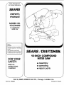
owner's
manual
MODEL NO.
113.234600
10" COMPOUND
MITER SAW
Serial
Number
Model and serial numbers
may be found on the motor
cover.
You should record both
model and serial number in
a safe place for future use.
FOR YOUR
SAFETY:
READ ALL
INSTRUCTIONS
CAREFULLY
_'_:_AIRS/ CRRFT$ IVlRN
10-1NCH COMPOUND
MITER SAW
• assembly
• operating
• repair parts
Sold by SEARS, ROEBUCK AND CO., Chicago,
Part No. SP5404
IL 60684
U.S.A.
Printed
in Taiwan.
FULL ONE YEAR WARRANTY
ON CRAFTSMAN
MITER SAW
If within one year from the date of purchase, this Craftsman Miter Saw fails due to a defect in
material or workmanship, Sears will repair it, free of charge.
WARRANTY SERVICE IS AVAILABLE BY SIMPLY CONTACTING THE NEAREST SEARS SERVICE CENTER/DEPARTMENT THROUGHOUT THE UNITED STATES.
This warranty
applies only while this product is used in the United States.
This warranty gives you specific legal rights, and you may also have other rights which vary
from state to state.
SEARS, ROEBUCK AND CO., D/817 WA Hoffman Estates, IL 60195
SAFETY INSTRUCTIONS
FOR MITER SAW
Safety is a combination of common sense, staying alert
and knowing how your miter saw works. Read this manual to understand this miter saw.
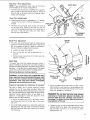
Place the miter saw so neither the user nor bystanders
are forced to stand in line with the blade. Thrown debris
could injure people in its path.
BEFORE
To avoid injury from unexpected saw movement:
• Put the miter saw on a firm level surface where there
is plenty of room for handling and properly supporting
the workpiece.
USING THE MITER
SAW:
WARNING: To avoid mistakes that could cause
serious, permanent injury, do not plug the miter
saw in until the following steps are completed.
• Assembly and alignment. (See pages 9-13)
• Learn the use and function of the ON-OFF switch,
upper and lower blade guards, handle latch, bevel
clamp, cover plate stop screw, and fence clamps.
(See page 8).
• Review and understand all safety instructions and
operating procedures in this manual,
• Review the maintenance methods for this miter saw.
(See page 23).
Read the following DANGER label found on the top of
the miter saw:
• Support the miter saw so the table is level and the
saw does not rock.
• Bolt or clamp the saw to its support.
• NEVER STAND ON TOOL. Serious injury could
occur if the tool tips or you accidentally hit the cutting
tool. Do not store anything above or near the toot
where anyone might stand on the tool to reach them.
To avoid injury or death from electrical shock:
• THIS TOOL IS DOUBLE INSULATED to give you
added protection. Double insulation does not take
the place of normal safety precautions when operating this tool. When servicing this double insulated
tool, use only identical parts.
• Make sure your fingers do not touch the plug's metal
prongs when plugging or unplugging the miter saw.
BEFORE
WHEN
INSTALLING OR MOVING
THE MITER SAW.
Before moving the saw, lock the miter, bevel and power
head positions. Unplug the power cord.
To avoid back injury, get help whenever you need to lift
the miter saw more than 10 inches.
NEVER carry the saw by the cord or power head handle.
Damage to insulation could cause an electric shock.
Damage to wire connections could cause a fire.
AVOID DANGEROUS ENVIRONMENT Use the miter
saw in a dry, indoor place protected from rain. Keep
work area well lighted.
EACH USE:
Inspect your miter saw,
DISCONNECT THE MITER SAW. To avoid injury from
accidental starting, unplug the saw, before changing
the setup, changing the blade or adjusting anything.
Compare the direction of rotation arrow on the guard
to the direction arrow on the blade. The blade teeth
should always point downward at the front of the saw.
Tighten the arbor screw.
Tighten the cover plate stop screw.
CHECK DAMAGED PARTS. Check for:
• Alignment of moving parts,
• Damaged electric cords.
• Binding of moving parts,
• Broken parts,
• Stable mounting,
• Function of arm return spring and lower guard: Push
the arm all the way down. then let it rise up until it
stops by itself. Check the lower guard to see if it
closed fully. If it did not, follow the instructions in the
Trouble Shooting section.
• Other conditions
saw works.
that may affect the way the miter
KEEP GUARDS IN PLACE, in working order, and in
proper adjustment.
If any part is missing, bent, or broken in any way, or
any electrical parts don't work, turn the saw off and
unplug it. REPLACE damaged, missing, or failed parts
before using the saw again.
MAINTAIN TOOLS WITH CARE. Keep the miter saw
clean for best and safest performance. Follow instructions for lubricating. DON'T put lubricants on the blade
while it's spinning.
REMOVE ADJUSTING KEYS AND WRENCHES from
tool before turning it on.
To avoid injury from jams, slips or thrown pieces:
• USE ONLY RECOMMENDEDACCESSORIES.
(See
page 23). Consult this Owner's manual for recommended accessories. Follow the instructions that
come with the accessories. The use of improper accessories may cause risk of injury to persons.
• Choose the right 10" inch diameter blade for the material and the type of cutting you plan to do.
• Make sure the blade is sharp, undamaged and properly aligned. With the saw unplugged, push the
power-head all the way down. Hand spin the blade
and check for clearance. Tilt the power-head to 45
degree bevel and repeat the check. If the blade hits
anything, make the adjustments shown in the Maintaining Maximum Cutting Capacity section.
• Make sure the blade and arbor collars are clean.
• Make sure the arbor collar's recessed sides are facing
the blade.
• Using a 1!2-inch box wrench, make sure the arbor
cap screw is firmly hand tightened.
• Make sure all clamps and locks are tight and no parts
have excessive play.
• KEEP WORK AREA CLEAN. Cluttered areas and
benches invite accidents. Floor must not be slippery.
To avoid burns or other fire damage, never use the
miter saw near flammable liquids, vapors or gases.
Plan ahead to protect your eyes,
hands, face, ears.
KNOW YOUR MITER SAW. Read and understand the
owner's manual and labels affixed to the tool. Learn its
application and limitations as well as the specific potential hazards peculiar to this tool.
To avoid injury from accidental contact with moving
parts, don't do layout, assembly, or setup work on the
miter saw while any parts are moving.
AVOID ACCIDENTAL STARTING. Make sure switch is
"OFF" before plugging miter saw into a power outlet.
Plan your work.
USE THE RIGHTTOOL Don't force toot or attachment
to do a job it was not designed to do. Use a different
tool for any workpiece that can't be held in a solidly
braced, fixed position.
CAUTION: This machine is not designed for cutting ferrous metals (steel, iron and iron based
metals). Use this miter saw to cut only wood,
wood like products or soft metals like aluminum.
Other materials may shatter, bind on the blade, or
create other dangers.
CAUTION: When cutting any metals, sparks or hot
I fragments could cause a fire. To avoid this, disI connect any dust collecting hose from the miter
I saw, and remove all traces of wood dust from
I inside dust traps n the miter saw.
Dress for safety.
WEAR
YOUR
SAFETY
Any power miter saw can throw foreign objects into the
eyes. This can cause permanent eye damage. Wear
safety goggles (not glasses) that comply with ANSI
Z87.1 (shown on package). Everyday eyeglasses have
only impact resistant lenses. They are not safety glasses. Safety goggles are available at Sears retail catalog
stores. Glasses or goggles not in compliance with ANSI
Z87.1 could seriously hurl you when they break.
• Do not wear loose clothing, gloves, neckties or
jewelry (rings, wrist watches) They can get caught
and draw you into moving parts.
• Wear nonslip footwear.
• Tie back long hair.
t-
_.,.O_
--!
o,_. __
• Roll long sleeves above the elbow.
• Noise levels vary widely. To avoid possible hearing
damage, wear ear plugs or muffs when using miter
saw for hours at a time.
• For dusty operations,
the safety goggles.
wear a dust mask along with
WARNING: If planning to cut aluminum or other
non-ferrous metals: Under adverse conditions, the
blade can grab and throw the workpiece suddenly
and unexpectedly. To avoid injury, follow all applicable safety instructions, as you normally would,
and:
Inspect your workpiece.
• Make sure there are no nails or foreign objects in
the part of the workpiece to be cut.
Plan your work to avoid THROWBACKS--when
the
workpiece binds on the blade and is torn from your
hands.
• Use only sawblades specifically recommended
for non-ferrous metal cutting.
•
Plan the way you will hold the workpiece from start to
finish:
Avoid awkward operations and hand positions where a
sudden slip could cause fingers or hand to move into
the blade.
Cut non-ferrous metals only if you are experienced or under the supervision
of an experienced person.
WHENEVER
DON'T OVERREACH. Keep good footing and balance.
• Keep the cut off piece free to move sideways after
it's cut off. Otherwise, it could get wedged against
the blade and thrown violently.
• Clear everything except the workpiece and related
support devices off the table before turning the miter
saw
on.
• SECURE WORK. Use clamps or a vise to help hold
the work when it's practical.
Use extra caution with large, very small or awkward
workpieces:
• Use extra supports (tables, saw horses, blocks, etc.)
for any workpieoes large enough to tip when not held
down to the table top.
• NEVER use another person as a substitute for a
table extension, or as additional support for a workpiece that is longer or wider than the basic miter saw
table, or to help feed, support or pull the workpiece.
• Do not use this saw to cut pieces too small to let you
easily hold the work while you keep the thumb side
of your index (pointer) finger against the outside edge
of the fence.
• When cutting irregularly shaped workpieces, plan
your work support so it will not slip, pinch the blade
and be torn from your hands. A piece of molding, for
example, must lie flat or be held by a fixture or jig
that will not let it twist, rock or slip while being cut.
• Properly support round material such as dowel rods,
or tubing. They have a tendency to roll while being
cut, causing the blade to "bite". To avoid this, always
use a fixture designed to properly hold your workpiece.
SAW
IS RUNNING.
WARNING: Don't let familiarity (gained from frequent use of your miter saw) cause a careless
mistake. A careless fraction
of a second is
enough to cause a severe injury.
Keep your face and body to one side, out of line with
a possible throwback.
Never cut FREEHAND:
• Brace your workpiece solidly against the fence and
table top so it will not rock or twist during the cut.
• Make sure there's no debris between the workpiece
and its supports.
• Make sure no gaps between the workpiece, fence
and table will let the workpiece shift after it is cut in
two.
Do not cut metal workpieces that must be hand
held. Use auxilliary clamps or other equipment
as needed.
Before starting your cut, watch the miter saw while it
runs. If it makes an unfamiliar noise or vibrates a lot,
stop immediately. Turn the miter saw off. Unplug the
miter saw. Do not restart until finding and correcting
the problem.
KEEP CHILDREN AWAY. Keep all visitors a safe distance from the miter saw. Make sure bystanders are
clear of the miter saw and workpiece.
Never confine the piece being cut off. Never hold it,
clamp it, touch it, or use length stops against it while
the blade is spinning. It must be free to move sideways
on its own. If confined, it could get wedged against the
blade and thrown violently.
Let the blade reach ful! speed before cutting.
DON'T FORCE TOOL. It will do the job better and safer
at its designed rate. Feed the blade into the workpiece
only fast enough to let it cut without bogging down or
binding.
Before freeing any jammed
• Turn switch "OFF".
material:
• Unplug the miter saw.
• Wait for all moving parts to stop.
After finishing a cut:
•
Keep holding the power head down.
•
Release the switch, and wait for al! moving parts to
stop before moving your hands.
•
If blade doesn't stop within 6 seconds, unplug the
saw and follow the instructions
in the Trouble
Shooting section for fixing the blade brake before
using the saw again.
BEFORE
LEAVING
THE SAW:
NEVER LEAVE TOOL RUNNING UNATTENDED. Turn
power off. Wait for all moving parts to stop.
Make workshop child-proof. Lock the shop. Disconnect
master switches. Remove the yellow switch key. Store
it away from children and others not qualified to use
the tool.
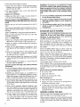
glossary of terms for woodworking
Arbor
The shaft on which
Bevel Cut
An angle cuthng
the work p_ece.
Resin
a cutting
operation
tool =s mounted
made
through
Compound
Cut
A simultaneous
bevel and m_ter cutting
Crosscut
A cutting
p_ece
operation
made across
A sticky, sap based
the face of
the width of the work
Freehand
Performing a cut without the use of fence (guide). hold
down or other proper device to prevent the workpiece
from twisting during the cutting operation
Twisting of
the workpiece can cause it to be thrown
Gum
A sticky
sap based
Heel
Misalignment
residue
from wood
that has hardened.
Revolutions
Per Minute (RPM)
The number of turns completed t_y a spinning
one minute
Sawblade
operalion
substance
obiect =n
Path
The distance that the tip of the sawblade tooth =s bent
ior set) outward from the face of the blade
Workpiece
The =tem on which the cutting operat=on _s being performed
The surfaces of a workp=ece are commonly
referred to as faces, ends, and edges
products.
of the blade
END
Miter Cut
LEDGE
An angle cutting
the work p=ece
operation
made
across
the width
of
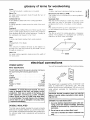
electrical connections
POWER
SUPPLY
Your unit has a plug that looks like the one shown below.
Motor Specifications
The AC motor used in this saw is a universal, nonreversible type having the following specifications:
H.R ......................................
3
Voltage .................................
120
Amperes .................................
15
Hertz (Cycles) ............................
60
Phase ................................
Single
RPM ..................................
5200
Rotation of Shaft ....................
Clockwise
Brake .............................
Automatic
WARNING: To avoid electrical hazards, fire hazards, or damage to the tool, use proper circuit
protection. Your saw is wired at the factory for
120V operation. Connect to a 120V, 15-AMP,
branch circuit and use a 15-AMP time delay fuse
or circuit breaker. To avoid shock or fire, if power
cord is worn or cut, or damaged in any way, have
it replaced immediately.
DOUBLE
INSULATED
The miter saw is double insulated to provide a double
thickness of insulation between you and the tool's electrical system, All exposed metal parts are isolated from
the internal metal motor components
with protecting
insulation,
This power tool is equipped
with a 2-conductor
cord
listed by Underwriters
Laboratories
(UL)The
plug
permits you to use any conventional
120-volt electrical
outlet without
necessity
for maintaining
a ground
connection.
CAUTION:
Double insulation
does not take the I
place of normal safety precautions
when operating this tool.
DANGER: To avoid electrocution:
1. Use only identical replacement parts when servicing a tool with double insulation. Servicing
should be performed by a qualified service
technician.
2. Do not use in rain or where floor is wet.
This tool is intended for indoor residential use
only.
{:=:
Oo
_==
ILl
The area of the workp_ece or table top directly in line
w_th e=ther the travel of the blade or the part of the
workpiece which will be or has been. cut by the blade
Set
Kerf
The amount of material
removed by the blade in a
through cut or the slot produced by the blade _n a nonthrough or partial cut
--
0
MOTOR
SAFETY
PROTECTION
CAUTION:
To avoid motor damage,
this motorl
should be blown out or vacuumed
frequently
to J
keep sawdust from interfering with normal motor I
ventilation.
J
1. Connect this tool to a !20V. 15-amp branch circuit
with a 15-amp time delay fuse or circuit breaker.
Using the wrong sbze fuse can damage the motor.
2. If the motor won't start, release the trigger switch
immediately
UNPLUG THE TOOL. Check the saw
blade to make sure it turns freely. If the blade is free,
try to start the motor again. If the motor still does
not start, refer to the 'Motor Trouble-Shooting
Chart."
3. If the motor suddenly stalls while cutting wood, release the trigger switch, unplug the tool, and free
the blade from the wood. The motor may now be
restarted and the cut finished.
4. Fuses may "blow"
quently if:
a
b.
or circuit
breakers
may trip fre-
MOTOR
IS OVERLOADED--Overloading
can
occur if you feed too rapidly or make too many
start/stops
in a short time.
Voltages not more than 10°o above or below the
nameplate voltage can handle normal loads For
heavy loads, however,
the voltage
at motor
terminals
must equai the voltage specified
on
nameplate
5. Most motor troubles may be traced to loose or incorrect connections,
overload,
low voltage
(such as
small size wire in the supply circuit) or to overly )ong
supply circuit wRre Always check the connections.
the load and the supply crcud whenever
motor
doesnt work well Check wre sizes and length _,,,th
the W,re Size (}hart beow
F(_ c_rcu_ls that
eectr cal service
proportonate
Saw rPotor
WIRE
are farther
than
100 feet away
_om
box
the ;,,_re s_ze must De _lcreased
y _rl order
to delwer
ampie
voltage
to the
SIZES
The alSO of any extension cord will cause some loss of
power To keel) this to a mm_mum anc to prevent overheating and motor burn-out
use the table beiow to
dete,m_ne the r's_nlmum wre s_ze IAWG
) extension
cord
Length of the
Conductor
Wire Sizes Required For 120V
(American Wire Gage Number)
0-25 Ft,
26-50 Ft.
51-100Ft.
16
14
12
contents
Page
Guarantee .................................
Safety Instructions for Miter Saw ...............
Glossary of Terms for Woodworking
............
Electrical Connections .......................
Unpacking and Preassembly ..................
Knowing Your Miter Saw .....................
2
2
5
5
7
8
Page
Assembly and Alignment .....................
Mounting the Saw .........................
Basic Saw Operations ......................
Maintenance and Lubrication .................
Trouble Shooting ..........................
Repair Parts ..............................
9
13
18
23
24
26
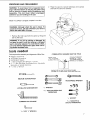
UNPACKING
AND PREASSEMBLY
WARNING: To avoid injury from unexpected starting or electrical shock, do not plug the power cord
into a source of power during unpacking and
assembly. This cord must remain unplugged
whenever you are working on the saw.
2. Place the saw on a secure stationary work surface
and look the saw over carefully.
Model 113.234600 is shipped complete in one box.
WARNING: Although small, this saw is heavy. To
avoid back injury, get help whenever you have to
ft the saw more than 10 inches.
1. Remove the miter saw from the carton by lifting the
saw by the base.
WARNING: If any part is missing or damaged, do
not plug the saw in until the missing or damaged
part is correctly replaced. To avoid electric shock,
use only identical replacement parts when servicing doub e nsu ated tools.
tools needed
Tools required
for assembly
and alignment
•
Medium
•
•
•
•
#2 Phillips Screwdriver
Combination
Square
':_ Box End/Open
End Wrench or Socket
2 - 1_6 Box End/Open End Wrenches or Adjustable
Wrenches or Socket Wrenches
-%6" Hex "L:' Wrench
•
Screwdriver
MEDIUM
COMBINATION
of Miter Saw:
SQUARE
DRAW
LIGHT
LINE ON BOARD
ALONG
THIS
EDGE_
MUST
BE TRUE
STRAIGHT
EDGE OF
BOARD
3t4" THICK
\
.-;
_',_ .A
7t')3_,P, ./
THIS EDGE MUST BE
PERFECTLY
SHOULD
BE NO GAP OR OVERLAP
SQUARE
IS FLIPPED
OVER
IN
STRAIGHT
WHEN
DOTTED
POSITION
SCREWDRIVER
ADJUSTABLE WRENCH
#2 PHILLIPS SCREWDRIVER
1/2"WRENCH
€_
Wld' BOX END/OPEN END
WRENCHES
I_"SOCKET
COMBINATION
%d' HEX "L'
SQUARE
WRENCH
c_
oz. _,,)
1%d'SOCKETS
&
SOCKET WRENCHES
knowing your miter saw
1.
WARNING
1. Warning label
2 Handle Latch--The
miter saw can be locked
lowered position for compact storage
LABEL
in the
3. Fence Lock Handles--The
fence has two positions
for increased
crosscut capacity. The lock handles
secure the fence to the base The saw is shipped
with the fence in the front position
2.
HANDLE
LATCH
NOTE: If the fence is being used in the rear position,
the two fence lock handles must be loosened before
changing the miter angle. Then tighten the fence handle
at the desired miter angle before starting a cut,
4
Miter Lock Handle
The miter lock handle securely
locks the miter saw at a desired miter angle. Index
points have been provided at0, 22,5 R!L and 45 RiL.
5. Bevel Lock Handle--The
bevel lock handle locks
the miter saw at a desired bevel angle.
6. Lower Blade Guard--The
blade guard helps protect
your hands from the blade in the raised position, To
avoid binding on the workpiece,
it retracts as the
blade is lowered,
7. Miter
Saw
Handle--The
saw
handle
contains
the
trigger switch with a lock-off button. The blade is
lowered into the workpiece by pushing down on the
handle, The saw will return to its upright position
when the handle is released.
5.
,
BEVEL LOCK
HANDLE
FENCE LOCK
HANDLE
POWER CORD
BEVEL
SCALE
UPPER BLADE
GUARD
LOCK OFF
BUTTON
,
MITER SAW
HANDLE
DUST
BAG
_ER
SWITCH
.
LOWER BLADE
GUARD
FENCE
c
=
FENCE LOCK
HANDLE
4.
LOCK
HANDLE
MITER
SCALE
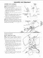
assembly and alignment
ASSEMBLY
Assembling
AND
HANDLE
LATCH
ALIGNMENT
the Lower
Blade
NOTE: For compact shipment
has been partially disconnected
\
Guard
the lower
blade
guard
1. The miter saw =s equipped with a handle latch used
to lock the miter saw in the lowered position,
To
release, push the handle down slightly and turn the
handle latch to the other side.
2
Release the handle
up position.
latch
and raise the saw to its
3. Slide the lower guard assembly
down until the
groove in the mounting plate rests on the front screw.
Tighten the screw with a phillips screwdriver
4
1/4-20
SHOULDER
LINK
PIVOT
SCREW
\
Remove the _4-20 shoulder screw from the pivot
casting as illustrated. Attach the blade guard link to
the pivot casting with a phillips screwdriver.
NOTE: With the blade guard link attached,
the guard
should raise as the blade is lowered towards the work
table and drop to cover the blade as the power head
is raised. This link helps prevent guard hangups and
MOUNTING
PLATE
BLADE GUARD
LINK
\
==....,I_
binding
while you are cutting
__
" ,'_
-_E
,,=I:
PIVOT
CASTING
Assembly
J
/_
/
,_
'_"
JJ
J
LOWER
BLADE GUARD
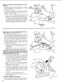
and Alignment
Step One--Blade
Square
to Table
NOTE: The miter saw was assembled,
aligned, and
inspected
before
shipment,
Alignment
should
be
checked and any adjustments
made to insure accurate
cuts.
1 Check miter lock handle setting. The miler lock handle should be at the 0 position
To reset the miter
angle, turn the miter lock handle counter clockwise
and press down the index spring
2. Lower the blade and lock the handle latch_ Use the
combination
square to check blade squareness
to
table. If the blade does not contact lhe full length of
the square, follow the alignment procedure
a
Loosen
bevel lock handle
b. Grasping
metal upper guard, move the culting
head left or right until blade makes contact with
the full length of tile square
c. Tighten
3
the bevel lock handle.
Check the bevel indicator. If indicator needs adjustment use a phillips
screwdriver
and slide the
indicator to the 0 on the scale.
\
\
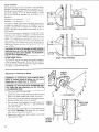
Step Two--Checking
Table Slot
and Aligning
Blade
with Turn
1. The blade should look like it's parallel to the sides
of the turn table slot. The blade should be 'W' closer
CAP
s(
to left side than right.
2
If blade looks parallel with turn table slot proceed
to step three. If necessary,
realign blade with turn
table slot, adjust as follows.
a.
Use a 516_'hex "lj' wrench to loosen (but do not
remove) the two cap screws that attach pivot
support to turn table. Move blade power-head so
it is parallel with turn table slot. Securely tighten
cap screws, Recheck blade position and readjust
if necessary.
Always check blade clearance
to
table when the miter saw is fully tilted to the left
TURN TABLE
SLOT
StepThree--Checking
and Adjusting
ness to Fence (Front Fence Position)
Blade Square-
1. To check blade squareness to fence, use a combination square
Place the square against the fence and
next to the blade as illustrated. Place the square so
the set in the teeth won't hold it from the blade. The
blade should contact the full length of the square
2. If blade contacts full length of square, proceed to
next step If blade is not square to the fence, follow
the alignment procedure.
a. Loosen miter lock handle a half turn. The latch
handle should still be secured with blade in lowered position.
NOTE: Take the
plywood
saw
off
its stand,
base if readjustment
CAUTION: To keep from losing control
steady the base with one hand while
the two bolts
with the other
bench
or
is necessary.
of the unit,
loosening
hand.
b. With the unit securely resting on a large stable
surface, tilt the unit by lifting up on one side or
the other of the base. Loosen the two miter arm
bolts on the underside
of the turn table with a
b{' wrench or socket. Tilt the unit by lifting up on
one side or the other of the base.
c. Return the saw to its normal resting position.
Make sure the miter lock handle is loose but do
not release the index spring.
d. Use the miter saw handle to turn the turn table
and saw so that the blade contacts the full length
of the square. Watch out for tooth set. Turn the
miter lock handle clockwise to lock saw square
to fence
e. Tilt saw as in Step B and tighten
f. Recheck blade squarenesss
just if necessary.
Adjustment
of Miter Scale
bolts.
to fence and read-
Indicator
1. Loosen the phillips screws that hold the indicator in
place. Reposition the indicator and retighten screw.
10
[I
Ii
Step Four--Pivot
Adjustments
PIVOT BOLT
NOTE: These adjustments were made at the factory
and normally do not require readjustment.
/
1. The miter saw should rise completely to the up position by itself. If the saw will not raise by itself or if
there is play in the pivot joints the following adjustments are necessary.
Travel Pivot Adjustments
/
\
a. Hold the pivot bolt with an adjustable or 1_.'16"
wrench.
Loosen the hex lock nut with an adjustable or 15_6"
wrench.
HEX LOCK"
NUT
b. Recheck the saw travel. Saw should rise freely to
its up travel stop Check to see that the saw will
raise from all positions and there is no looseness in
the pivoL If saw still won't fully rise, have Sears
Service check and repair it.
Bevel
Pivot
Adjustment
1. The miter saw should bevel easily by loosening the
bevel lock handle and tilting the power head to the
left. If movement
is tight or if there is looseness in
the pivot follow the adjustment
procedure.
a. Loosen
ADJUSTABLE
WRENCH
DEPTH
STOP
the bevel lock handle.
b. Turn the hex lock nut with an adjustable
wrench.
or _6"
c. Recheck bevel movement of the miter saw. Readjust if necessary.
Depth Stop
The depth stop limits the blades downward travel It
allows the blade to go below the work table enough to
maintain ful! cutting capacities. The depth stop positions
the blade "/4"from the cast iron table support. The depth
stop is factory set and should never need adjustment.
Maintaining Maximum Cutting
Capacity
WARNING: To avoid injury from unexpected starting or electrical shock, do not plug the power cord J
into a source of power during unpacking and
assembly. This cord must remain unplugged
BEVEL LOCK
HANDLE
HEX LOCK
NUT
ADJUSTABLE
WRENCH
whenever you are working on the saw.
Unplug the saw before any adjustment is attempted.
Lower the blade into the slot of the turn table. Check
This tool is factory set to provide maximum cutting
capacity for the !0" saw blade provided. When the
diameter ot the blade has been reduced due to sharpening, if may be necessary to adjust depth stop to provide
maximum cutting capacity. When a new blade is tnstalled, it is necessary to check the clearance of the
blade to the turn table structure.
blade clearance and maximum cutting distance (distance from fence where blade enters) to front of turn
table slot. Readjust if necessary.
1. To adjust the depth stop use an adjustable wrench
and loosen the hex nut at the rear of the miter
saw arm.
2
Use a flat blade screwdriver to adjust the depth stop
adjusting bolt. The saw blade is lowered by turning
the bolt counterclockwise
and raised by turning the
bolt clockwise.
WARNING: Do not start
checking for interference
the turn table structure.
the blade if it strikes the
ing operation of the saw.
the miter saw without
between the blade and
Damage could result to
turn table structure dur-
4. Tighten the hex nut with an adjustable wrench while
carefully holding the depth stop adjusting bolt with
the flat blade screwdriver so it will not turn while
tightening hex nut.
11
Fence
Positions
The miter saw has two fence positions, The front fence
position is used for workpieces
up to standard 2 x 4 for
cut off and bevel operation,
floor and ceiling moldings,
and door casings.
The rear fence position
is used
for cut off and bevel operation
for a standard 2 x 6
workpiece.
Standard
2 x 4 measures
1_,/' x 3_,/'
Standard
2 x 6 measures
1_,5'' x 5_''
]
......
The base on either side of the work table has two sets
of holes for locating the fence. To change the fence
position, remove the two fence lock handles. Put the
fence in the other fence position and instali the fence
lock handles.
The rear fence position is designed to slide side to side
when the miter setting is changed
Th_s feature lets the
fence move to provide maximum support for the workpiece If it _s necessary
to change the miter cut in the
rear position, first loosen the fence lock handles. Release the miter lock handle and move it to the desired
miter angle. Tighten the miter lock handle and the fence
lock handles.
CAUTION: Do not try to change the miter position
while the fence is in the rear fence position before
loosening the fence lock handles. You might damage the fence alignment arm.
On/Off
Trigger
Switch
REAR
FENCE
POSITION
To prevent the trigger from being accidentally
engaged,
a lock-off button is provided, To start the tool, press in
the lock-off button and squeeze the trigger
Release
the trigger to stop the miter saw
ARBOR
SCREW
Removing or Installing the Blade
WARNING: To avoid injury from a thrown workpiece or thrown pieces of blade, do not use a
blade arger or sma er than 10" diameter.
WARNING: To avoid injury from unexpected starting, unplug the saw whenever you are removing
or installing the blade.
1 Unplug
the saw from the outlet.
2. Loosen the screw holding the lower guard mounting
plate to the upper guard with phillips screwdriver.
_"BOX
3, Lift the lower guard up and tilt the lower guard assembly back so the arbor screw is exposed
t
4, Find the arbor lock between the upper guard and
the miter saw handle. Place a _'_" box end wrench
over arbor screw.
5. Press the arbor lock and hold it in firmly while turning
the wrench clockwise. The arbor lock will engage
after some turning of the wrench,
6. Remove the arbor screw, arbor washen
collar, and the blade
outer blade
UPPER
BLADE
GUARD
12
/
WRENCH
,L
:3
/
/
_
[
MITER SAW
HANDLE
NOTE: Pay attention to pieces removed, noting their
position and direction they face (see illustration)
Wipe
the blade collars clean of any sawdust before installing
the new blades.
8.
Install the new 10" blade (see recommended
accessory list). Make sure the rotation arrow on the blade
matches the clockwise rotation arrow on the upper
guard.
9.
Install the ouler blade collar, arbor washer and
arbor screw. Press the arbor lock and turn the '.,2"
wrench
counter
clockwise
to secure the blade.
Tighten arbor screw securely.
ARBOR
WASHER
ARBOR
SCREW
ing plate rests all the way down on the locking
screw. Tighten the screw with phillips screwdriver.
11. Be sure the arbor
turns freely
lock is released
so the blade
NOTE: The arbor lock can be damaged by improper
use. If the arbor lock will not hold, lower the blade down
on to a scrap piece of wood positioned
against the
fence. This will serve as an alternate locking means.
OUTER
BLADE COLLAR
l
INNER BLADE
COLLAR
(DO NOT REMOVE)
sure I
the blade clears the table slot at the 0 and 45 I
bevel positions. Lower the blade into the lower I
table
and check
any contact
base or
WARNING:
After for
installing
a new with
blade,the
make
turn table structure.
tf blade contacts turn table, refer to assembly
ment. step two, for adjustment
BAG:
REMOVED
FOR CLARITY)
THE SAW
REAR
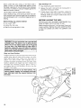
WARNING:movement:
To avoid
injury
from
unexpected
saw
a. Before moving the saw, lock the miter, bevel and
power-head
positions. Unplug electric cord
b. To avoid back injury, get help when
the saw more than 10 inches. Hold
your body. Bend your knees so you
legs, not your back. Lift by using the
at the bottom of the base.
REAR
e
o,J
HOLES
z
you need to lift
the tool close to
can lift with your
hand-hold areas
O
g
I
Place the saw so other people cannot stand behind
it. Thrown debris could injure people in its path.
Place the saw on a firm. level surface where there
is plenty of room for handling
ing the workpiece.
f
MOUNTING
HOLES
MOUNTING
c. Never carry the miter saw by the power cord or the
plastic handle. Carrying the tool by the power cord
could cause damage to the insulation
or the wire
connections
resulting in electric shock or fire.
d
and align-
If btade bottoms
out on turn table structure,
refer
to assembly
and alignment
depth stop section for
adjustment.
(DUST
MOUNTING
\
-
10, Lower the lower blade guard until the slot in mount-
DANGER: Never use saw without mounting plate
securely in place. It keeps the arbor screw from
falling out if it accidentally loosens, and prevents
the spinning blade from coming off the machine.
10" BLADE
and properly
support-
FORWARD
MOUNTING
HOLES
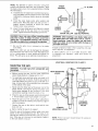
Support the saw so the table is level and the saw
does not rock.
Bolt or clamp the saw to its support.
Place the saw in the desired location
bench or the recommended
leg set
saw has four holes to mount the miter
tion), If the saw is to be used in one
to the work bench or leg set
either on a work
The base of the
saw (see illustralocation, fasten it
MOUNTING
NOTE: Fence
rear mounting
HOLES
has been
holes
moved forward
for access
to
13
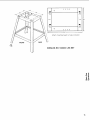
If the saw is to be used in a portable application,
mount
the saw to a 34" piece of plywood. The mounting board
can then be clamped down to prevent it from tipping.
MOUNTING
BOLTS
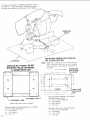
MOUNTING BOARD FOR CATALOG
NO. 9-22244 LEG SET
3/4"
PLYWOOD
NOTE:
CATALOG NO. 9-22246 LEG SET
MOUNTING HOLES FOR MODEL
113.234600 MITER SAW
0
o
__6,,_
o I
o
Attach the mounting board to the leg set first.
Then mount the mite_ saw to the mounting
board using the recommended
hardware inot
included)
drill ;_"dia. holes
HOLES FOR
MTG. BOARD
12,._1f
TO LEG SET
147'
©
o
o
t'4q-*
©
[
51_ '
O
?'
I
o
--
jA
0
___@
....
_D_
=
-4
o
i°o
o°i0
0 _0°o
o ;
STIFFENER--END
_--
STIFFENER
Attach
,÷
0
-- SIDE
miter saw to holes
Recommended
mounting hardware
4-%6-18 x 3 hex head bolts
4W_, flat washers
4-", _,lock washers
4-%_, hex nuts
indicated
r
-_
-....
FRONT
'4"+'_15
:'"
.!
I
HOLES FOR
MTG. MITER
SAW
--24"
Recommended
hardware (not included)
Mounting board to legset
4-_".;-18 x lV2 hex head bolts
4-._A,_flat washers
4-R.,e lock washers
4-'_, hex nuts
(not included)
Mounting miter saw to mounting
4-s _6-18 x 3W hex head bolts
4-5,_ flat washer
4-__ lock washer
4:" r hex nuts
board
o
o
o
o
14"
Attach
FRONT
mounting
board
.,,!
to holes
indicated
SIDE
CATALOG
NO. 9-22244
LEG SET
o
o"J ._,
._o
rn O
15
BEFORE
USING THE MITER
SAW:
WARNING: To avoid mistakes that could cause
serious permanent injury, do not plug the miter
saw n until the following
steps are completed.
• Assembly and alignment. (See pages 9-13 ).
To avoid injury from jams, slips or thrown pieces:
• USE ONLY RECOMMENDEDACCESSORIES.
(See
page 23). Consult this Owner's manual for recommended accessories. Follow the instructions that
come with the accessories. The use of improper accessories may cause risk of injury to persons.
• The saw is properly mounted. (See pages 13-15).
• Learn the use and function of the ON-OFF switch,
upper and lower blade guards, handle latch, bevel
clamp, cover plate stop screw, and fence clamps.
(See page 8).
• Review and understand all safety instructions and
operating procedures in this manual.
• Review the maintenance methods for this miter saw.
(See page 23).
• Choose the right 10" inch diameter blade for the material and the type of cutting you plan to do.
To avoid injury or death from electrical shock:
• Make sure the arbor collar's recessed sides are facing
the blade.
• Make sure your fingers do not touch the plug's metal
prongs when plugging or unplugging the miter saw.
BEFORE
EACH
USE:
Inspect your miter saw.
DISCONNECT THE MITER SAW. To avoid injury from
accidental starting, unplug the saw, before changing
the setup, changing the blade or adjusting anything.
Compare the direction of rotation arrow on the guard
to the direction arrow on the blade. The blade teeth
should always point downward at the front of the saw.
Tighten the arbor screw.
Tighten the cover plate stop screw.
CHECK DAMAGED PARTS. Check for:
• Alignment of moving parts,
• Damaged electric cords.
• Binding of moving parts,
• Broken parts,
• Stable mounting,
• Function of arm return spring and lower guard: Push
the arm all the way down, then let it rise up until it
stops by itself. Check the lower guard to see if it
closed fully. If it did not, follow the instructions in the
Trouble Shooting section.
• Other conditions that may affect the way the miter
saw works.
KEEP GUARDS IN PLACE, in working order, and in
proper adjustment.
If any part is missing, bent, or broken in any way, or
any electrical parts don't work, turn the saw off and
unplug it. REPLACE damaged, missing, or failed parts
before using the saw again.
MAINTAIN TOOLS WITH CARE. Keep the miter saw
clean for best and safest performance. Follow instructions for lubricating. DON'T put lubricants on the blade
while it's spinning.
REMOVE ADJUSTING KEYS AND WRENCHES from
tool before turning it on.
16
• Make sure the blade is sharp, undamaged and properly aligned. With the saw unplugged, push the
power-head all the way down. Hand spin the blade
and check for clearance. Tilt the power-head to 45
degree bevel and repeat the check. If the blade hits
anything, make the adjustments shown in the Maintaining Maximum Cutting Capacity section.
• Make sure the blade and arbor collars are clean.
• Using a 1/2-inch box wrench, make sure the arbor
cap screw is firmly hand tightened.
• Make sure all clamps and locks are tight and no parts
have excessive play.
• KEEP WORK AREA CLEAN. Cluttered areas and
benches invite accidents. Floor must not be slippery.
To avoid burns or other fire damage, never use the miter
saw near flammable liquids, vapors or gases.
Plan ahead to protect your eyes,
hands, face, ears.
KNOW YOUR MITER SAW. Read and understand the
owner's manual and labels affixed to the tool. Learn its
application and limitations as well as the specific potential hazards peculiar to this tool.
To avoid injury from accidental contact with moving
parts, don't do layout, assembly, or setup work on the
miter saw while any parts are moving.
AVOID ACCIDENTAL STARTING. Make sure switch is
"OFF" before plugging miter saw into a power outlet.
Plan your work.
USE THE RIGHTTOOL. Don't force tool or attachment
to do a job it was not designed to do. Use a different
tool for any workpiece that can't be held in a solidly
braced, fixed position.
CAUTION: This machine is not designed for cutting ferrous metals (steel, iron and iron based
metals). Use this miter saw to cut only wood,
wood like products or soft metals like aluminum.
Other materials may shatter, bind on the blade, or
create other dangers.
CAUTION: When cutting any metals, sparks or hot
fragments could cause a fire. To avoid this, disconnect any dust collecting hose from the miter
saw, and remove all traces of wood dust from
inside dust traps in the miter saw.
Dress for safety.
Any power miter saw can throw foreign objects into the
eyes. This can cause permanent eye damage. Wear
safety goggles (not glasses) that comply with ANSI
Z87.1 (shown on package). Everyday eyeglasses have
only impact resistant lenses. They are not safety glasses. Safety goggles are available at Sears retail catalog
stores. Glasses or goggles not in compliance with ANSI
Z87.1 could seriously hurt you when they break.
• Do not wear loose clothing, gloves, neckties or
jewelry (rings, wrist watches) They can get caught
and draw you into moving parts.
• Wear nonslip footwear.
• Tie back long hair.
• Roll long sleeves above the elbow.
• Noise levels vary widely. To avoid possible hearing
damage, wear ear plugs or muffs when using miter
saw for hours at a time.
• For dusty operations, wear a dust mask along with
the safety goggles.
Inspect your workpiece.
• Make sure there are no nails or foreign objects in
the part of the workpiece to be cut.
Plan your work to avoid THROWBACKS--when
the
workpiece binds on the blade and is torn from your
hands.
Plan the way you will hold the workpiece from start to
finish:
Avoid awkward operations and hand positions where a
sudden slip could cause fingers or hand to move into
the blade.
DON'TOVERREACH,
Keep good footing and balance.
Keep your face and body to one side, out of line with
a possible throwback.
Never cut FREEHAND:
• Brace your workpiece solidly against the fence and
table top so it will not rock or twist during the cut.
• Make sure there's no debris between the workpiece
and its supports.
• Make sure no gaps between the workpiece, fence
and table will let the workpiece shift after it is cut in
two.
• Keep the cut off piece free to move sideways after
it's cut off. Otherwise, it could get wedged against
the blade and thrown violently.
• Clear everything except the workpiece and related
support devices off the table before turning the miter
saw on.
• SECURE WORK. Use clamps or a vise to help hold
the work when it's practical.
Use extra caution with large, very small or awkward
workpieces:
• Use extra supports (tables, saw horses, blocks, etc.)
for any workpieces large enough to tip when not held
down to the table top.
• NEVER use another person as a substitute for a
table extension, or as additional support for a workpiece that is longer or wider than the basic miter saw
table, or to help feed, support or pull the workpiece.
• Do not use this saw to cut pieces too small to let you
easily hold lhe work while you keep the thumb side
of your index (pointer) finger against the outside edge
of the fence.
• When cutting irregularly shaped workpieces, plan
your work support so it will not slip, pinch the blade
and be torn from your hands. A piece of molding, for
example, must lie flat or be held by a fixture or jig
that will not let it twist, rock or slip while being cut.
• Properly support round material such as dowel rods,
or tubing. They have a tendency to roll while being
cut, causing the blade to "bite". To avoid this, always
use a fixture designed to properly hold your workpiece.
WARNING: If planning to cut aluminum or other
non-ferrous metals: Under adverse conditions, the
blade can grab and throw the workpiece suddenly
and unexpectedly. To avoid injury, follow all applicable safety instructions, as you normally would,
and:
•
Use only sawblades specifically recommended
for non-ferrous metal cutting.
•
Do not cut metal workpieces that must be hand
held. Use auxilliary clamps or other equipment
as needed.
• Cut non-ferrous metals only if you are experienced or under the supervision of an experienced person,
WHENEVER
SAW IS RUNNING.
WARNING: Don't let familiarity (gained from frequent use of your miter saw) cause a careless
mistake. A careless fraction
of a second is
enough to cause a severe njury.
Before starting your cut, watch the miter saw while it
runs. If it makes an unfamiliar noise or vibrates a lot,
stop immediately. Turn the miter saw off. Unplug the
miter saw. Do not restart until finding and correcting
the problem.
KEEP CHILDREN AWAY. Keep all visitors a safe distance from the miter saw. Make sure bystanders are
clear of the miter saw and workpiece.
17
Never confine the piece being cut off. Never hold it,
clamp it, touch it, or use length stops against it while
the blade is spinning. It must be free to move sideways
on its own. If confined, it could get wedged against the
blade and thrown violently.
After finishing
Let the blade reach full speed before cutting.
DON'T FORCE TOOL. It will do the job better and safer
at its designed rate. Feed the blade into the workpiece
only fast enough to let it cut without bogging down or
binding.
•
Keep holding the power head down
•
Release the switch, and wait for all moving parts to
stop before moving your hands.
•
If blade doesn't stop within 6 seconds, unplug the
saw and follow the instructions
in the Trouble
Shooting section for fixing the blade brake before
using the saw again.
BEFORE
Before freeing any jammed
• Turn switch "OFF".
material:
• Unplug the miter saw.
• Wait for all moving parts to stop.
a cut:
LEAVING THE SAW:
NEVER LEAVE TOOL RUNNING UNATTENDED. Turn
power off. Wait for all moving parts to stop.
Make workshop child-proof. Lock the shop. Disconnect
master switches. Remove the yellow switch key. Store
it away from children and others not qualified to use
the tool.
WARNING: For your convenient use, your saw has
a blade brake. The brake is not a safety device.
Never rely on it to replace proper use or the guard
on your saw. If the blade does not stop within 6
seconds, unplug the saw and follow the instructions in the Trouble Shooting section for fixing the
brake before using saw again.
Body and Hand Position
Proper positioning of your body and hands when operating the miter saw will make cutting easier and safer.
Never place hands near cutting area Place hand at
least 4" from path of blade, Hold workpiece firmly to
the fence to prevent movement towaro the blade Keep
hands in position until trigger has been released and
the blade has completely stopped, Before making a
cut, make a "dry run" with the power off so you can see
the path of the blade.
WARNING: Do not try to cut short pieces. You
cannot properly support the workpiece and keep
your hold down hand the required distance from
the b ade.
18
.--.
o_
s13
q3_
,-n o
MiterCut
Whena mitercut is required,movethe sawto the
desiredangle.Donot standin frontofthe sawtable.
Movewiththehandtetothemiterangletomakethecut
NOTE:Remember
to loosenthe fencelockhandles
beforechangingthe miteranglewiththe fencein the
rearposition.
\
Bevel
\
Cut
When a bevel cut is required, tilt the blade to desired
bevel angle. Stand to the left side of the handle to make
the cut.
\
O
.o ._
c_
mC:)
19
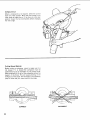
Compound
Cut
When a compound
cut is required, select the correct
bevel and miter position. Move with the handle to the
miter angle to make the cut if the fence is in the rear
position, loosen the two lock handles before changing
the miter angle
Cutting Bowed Material
Before cutting a workpiece, check to make sure it is
not bowed. If it is bowed the workpiece must be
positioned and cut as illustrated. Do not position workpiece incorrectly or try to cut the workpiece without the
support of the fence. This will cause pinching of the
workpiece on the blade. The workpiece could suddenly
jump or move and your hand could hit the blade.
CORRECT
20
INCORRECT
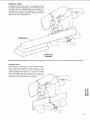
Workpiece
Support
Long pieces need extra supports• The supports should
be placed along the workpiece so the workpiece does
not sag and your hand holding
the workpiece
is
positioned 4" or more from the blade path. The support
should let the workpiece
lay flat on the base and work
table during the cutting operation
_
/-
\
WORKPIECE
SUPPORT
Auxiliary
Fence
Certain types of molding need a fence face extension
due to the size and position of the workpiece
Holes
are provided in the fence to attach an auxiliary fence
made of straight wood typically 1_ inch thick by 3 inches
high by 20 inches long. The auxiliary fence is used with
the saw in the 0 bevel position. If a bevel cut is desired,
the auxiliary fence will have to be removed.
o_
eoO
21
O,,)
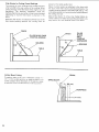
Filler
Blocks
for Cutting
Crown
Moldings
placed
The majority of crown moldings have contact surfaces
of 52: and 38 to the rear surface of the molding. When
joining the face of the filler block these angles must be
maintained.
The
following
illustrations
show
two
methods that can be used when cutting crown moldings
depending
on how the filler block is attached
to the
fence.
When the filler blocks
filler blocks pointing
are attached with the face of the
upwards, the molding must be
on the table upside
down
When the filler blocks are attached to the fence with
the face of the filler blocks pointing downwards,
the
molding must be placed on the table right side up. This
is the same position as it would be when nailed between
the ceiling and wall.
Make 2 filler blocks 10 inches long Fasten blocks securely to fence. For block face pointing downward, you
may need to drill new fastener holes in the fence.
FENCE
FILLER BLOCK FACE
POINTING UPWARD
FILLER
BLOCK
FACE
POINTING
_jFENCE
MOLDING
,_____
/
TABLE
/
Vertical
Bevel
I
FENCE
Cutting
To make a miter cut in a 2 x 4 workpiece Cactual 1_ ''
x 3_. '') in the vertical position (on edge) a spacer, such
as the auxiliary fence described on the prevfous page.
is required. Fence is located =nthe front fence position
MOLDING
SPACE
BLOCK
\
31/2" (89 mm)
I
I_WORKPIECE
I
--.-I 1%" (41 turn)
I
!
!
maintenance and lubrication
Maintenance
Always unplug the power cord before any maintenance
check on this saw.
DANGER: Never put lubricants on the blade while
it's spinning.
WARNING: If blowing sawdust, wear proper eye
protection to keep debris from blowing into eyes.
Recommended
WARNING: To avoid injury from unsafe accessories, use only accessories shown on the recommended accessories list in this manual.
WARNING: To avoid injury from unexpected starting or electrical shock, unplug the power cord
before working on the saw.
WARNING: For your safety, this saw is double
insulated. To avoid electrical shock, fire or injury,
use only parts identical to those identified in the
parts list. Reassemble exactly as original assembly to avoid electrical hazards.
Replacing
Carbon
Brushes
The carbon brushes furnished
will last approximately
50 hours of running time or 10.000 on/off cycles Replace both carbon brushes when either has less than
_.," length of carbon remaining.
To inspect or replace
first unplug the saw. Then remove the black plastic cap
on the side of the motor (caution, this cap is spring
loaded by the brush assembly). Then pull out the brush.
Repeat for the other side. To reassemble
reverse the
procedure.
The ears on the metal end of the Drush
assembly go in the same hole the carbon part fits into
Tighten the cap snugly but do not overtighten.
Prohibited Accessories--The
use of any cutting tool
except 10" saw blades which meet the requirement
under recommended
accessories
_s prohibited. Do not
use accessories
such as shaper cutters or dado sets.
Ferrous metal Imetal with iron in it) cutting and the use
of abrasive wheels are prohibited. See DANGER NOTE
(BASIC SAW OPERATIONS)if
planning to saw non-ferrous metal
Leg Sets
............................
Carbide-Tipped
Blades marked
8" Arbor Hole
Lower
Lubrication
Guard
Do not use the saw without the lower guard The lower
blade guard is attached to the saw for protection. Should
the lower guard become damaged, do not use the saw
until damaged
guard has been replaced.
Develop a
regular check to make sure the lower guard is working
properly. Clean the lower guard of any dust or build up
with a damp cloth.
CAUTION:
Do not use solvents
cou d make the plastic
WARNING:
c oudy
When cleaning
lower
Basic Blade
10" Diameter
Infrequent
9-22246
See
See
See
See
Catalog
Catalog
Catalog
Catalog
See Catalog
See Catalog
9-23469
Requirements
for 5500
Lubrication
1 Lubrication
a
and br tt e.
saw from the outlet to avo d unexpected
Blades:
RPM or higher
All the motor bearings _n this tool are lubricated with a
sufficient amount of high grade ubricant for the Ire of
the unit under normal operating conditions,
therefore.
no fuqher lubrication
is required. (See below _
on the guard. They
guard unplug
9-22244
Trim Saw .......................
Cut-Off
........................
Combination
....................
Plywood/Particle
Board ............
Non-Carbide
Tipped Blades:
Cross Cut/Plywood
...............
Combination
....................
Miter Saw Accessory
Pack
...........
NOTE: To reinstall the same brushes, first make sure
the brushes go back in the way they came out This
will avoid a break in period that reduces performance
and increases wear.
Blade
Accessories
as Required:
of arm pwot fo _ free movement
By loosening nut and applying
to contact face (minor).
oti to washer
and
b. Dis-assembly
means required to grease pwot bolt
and contact faces (major',,
the
start-up.
NOTE:
Disassembly
should be done by an authorized service technician.
Removal of the upper
guard and the bolt stop is necessary
before pivot
can be disassembied,
Pay close attention
to the
spring-end
positions
=n the castings....mark
with
chalk to avoid later confusion
Saw Dust
Periodically,
sawdust will accumulate
under the work
table and base. This could cause difficulty in the movement of the work table when setting up a miter cut
Frequently blow out or vacuum up the sawdust
2
t-
Lubrication of mechanism
which pivots lower guard
Use light household
oil (sewing machine oil) on
metal-to-metal
or metai-to-plastic
guard contact
areas as required for smooth, quiet operation. Avoid
excess oil, to which sawdust will cling
t-
(1_
_... -_oj t._
23
TROUBLE
PROBABLE
PROBLEM
Brake does not stop
blade within
2-3 seconds.
Motor does not start.
SHOOTING
1 Brushes
GUIDE
SUGG ESTED CORRECTIVE
CAUSE
not seated
-Inspect/clean/replace
(see maintenance
or lightly sticking.
2. Motor brake winding-overheated from use of notrecommended
accessory
or rapid on/off cycling.
--Use
3. Arbor screw
--Retighten
--Let
loose
brushes
section).
a recommended
blade
cool down.
--Authorized
service. Check motor brake winding,
switch, condition of commutator.
1. Fuse
--15-Amp
Brushes
worn
--See
time delay fuse, or CKT. breaker.
"Maintenance,"
--Authorized
3. Other
1. Normal--automatic
brake
page 21.
service.
i
i
working
properly.
TROUBLE
SHOOTING
GUIDE
- GENERAL
SUGGESTED CORRECTIVE ACTION
PROBLEM
PROBABLE
Blade hits table.
1. Misatignment.
--See Assembly and Alignment, page 10
2. Damaged
---Get authorized Sears Service.
CAUSE
depth stop.
Angle of cut
not accurate.
1. Misalignment.
-See
Can't move
miter adjustment.
1. Fence in rear position
and clamp tight,
--Loosen
fence
next cut.
2. Sawdust
--Vacuum
or blow out dust.
WEAR EYE PROTECTION
under table
Power-head
wobbles.
1. Loose
Power-head
won't fully rise.
1. Pivot misadjustment.
Blade binds, jams,
burns wood,
Retighten
Step 4. page 12.
See Assembly
and Alignment.
Step 4, page 12.
Service.
3. Pivot spring not replaced
properly after service.
--Get
authorized
Sears
Service.
1. Improper operation.
--See
Basic
2. Dull blade.
--Replace
blade
Saw Operation.
or sharpen
--Replace
blade
1. Saw blade not round
--Replace
blade.
2. Saw blade damaged
-- Replace
blade.
3. Saw blade loose
--Tighten
,
Z
arbor
Get authorized
.....
page 16
blade.
--Replace
with 10" diameter
for the material being cut.
blade.
starting
and Alignment.
Sears
Improper
before
Assembly
authorized
4. Other
.....
--See
clamps,
-Get
4. Warped
Tool vibrates or
shakes.
pivot points
Assembty and Alignment. page 10
2. Part failure
3.
24
ACTION
4. Other.
2,
Brush sparking when
switch released.
- MOTOR
blade designed
screw
Sears
Service.
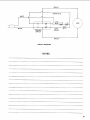
BRUSH
SHORT
BLUE
WHITE
LONG
II
II
BLACK
BRAKE
TRIGGER
SWITCH
BRUSH
CIRCUIT
DIAGRAM
NOTES
25
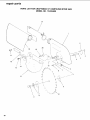
PARTS LIST FOR CRAFTSMAN
10" COMPOUND
MODEL NO. 113.234600
MITER SAW
1
2o._
19 ---,-_ _
23 "''_
\
\
26
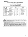
repair parts
PARTS LIST FOR CRAFTSMAN
10" COMPOUND
MODEL NO. 113.234600
Always order by Part Number--Not
FIGURE
Part
No.
Key
No.
2
3
4
5
6
7
8
9
10
11
12
Description
i
821664
820010
816673-1
816678
STD5108O2
STD551108
816716
816691
816690
816685
Blade Guard Asm.
(see Fig. 4)
Motor Asm. (see Fig. 2)
Fence
Arm-Fence
Table
Base (Includes Scale)
* Screw Pan H D, 8-32 x 5/16
* Lockwasher #8
Indicator-Miter
Spring-Index
Plate-Clamp
Arm-Miter
MITER SAW
by Key Number
1
Key
No.
Part
No.
13
14
15
16
17
816669
STD523108
STD551131
STD55!031
809727
18
19
20
816863-1
STD551137
141594-44
21
22
23
STD851004
817182
Description
Handle-Miter
,I]L* Bolt-Hex HD. 5/16-18 x 7/8
_* Lockwasher 5/16
_(_*Washer 11/32 x 11/16 x 1/16
Screw Flat HD. Type "T"
8-32 x 5/8
Clamp-Bolt
* Lockwasher 3/8
,_ ScrewSoc HD. Cap
3/8-16 x 1 1/2
Pivot Asm. (see Fig. 3)
* Washer 4 x 10 x 0.8mm
Washer 10x 19x 1.8mm
* Standard Hardware Item--May Be Purchased Locally
WARNING:
These Items Are Important To The Safety Of This Tool. Do Not Substitute Common
Parts.
0_
l..m
eD
OC
27
repa=r par-t
PARTS LIST FOR CRAFTSMAN
10" COMPOUND
MODEL NO. 113.234600
22
23
1
.-_+--
MITER SAW
2
\+
3
4
14
8
2
18
16
°
15
10
_
12
Always order by Part Number - Not by Key Number
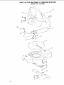
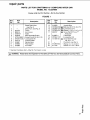
FIGURE 2 -- ARM AND MOTOR ASSEMBLY
WARNING: For your safety, this miter saw is specially insulated. To avoid electrical shock, fire or injury, use
only parts identical to those identified in the parts list. Reassemble exactly as originally assembled.
Key
No
Part
No.
1
2
3
4
5
6
7
8
9
10
1!
821122
816704
816768
816770
816740
816697
816696
818964
816743 1
816700
817143
12
13
14
15
818965
STD840407
816755
816701
•
Description
_. •
_, •
,_
_1_
Guard-Cord
Cord wlPlug
Brush
Cover-Brush
Protector-Wire
Lock-Switch
p.
iJJlL1- Spring-Switch Lock
Handle-R.H.
Screw Pan Hd M4 x 07-20
• Switch
Screw Pan Hd
TY "AB" M4 x 0.7-15
Handle-L.H
* Nut Hex M4 x 07
Screw Pan Hd M5 x 08-20
Button-Switch
Key
No
Pa_
No.
Description
16
17
18
19
816743
816725
816668
816698
2O
21
STD841015
*
_, •
816689-1
22
23
24
25
26
60047
816723
STD551110
818043
821121
SP5404
_*i,
,_
*
Screw Pan HD M4 x 0.7-15
Clamp-Cord
Cushion
Screw Set Slotted
M10 x 1.5
Nut Hex M10 x 1.5
Motor & Arm Asm.
(Includes Keys
1,2,34,5,16,17)
Washer .630 x 1 x 1/32
Nut Lock M16
Lockwasher #!0
Washer .350 x .170 x .03
Bushing
Owner"s Manual
(Not Illustrated)
WARNING: Any Attempt To Repair Or Replace Electrical Parts On This Unit May Create A HAZARD
Unless Repair Is Done By A Qualified Service Technician. Repair Service Is Available At Your Nearest
Sears Store.
* Standard Hardware Item--May Be Purchased Locally.
1- See Mechanical Assembly Caution on page 31
28
I _
I
WARNING:
These Items Are Important To The Safety Of This Tool. Do Not Substitute
Common Parts.
]
repair parts
PARTS
LIST FOR CRAFTSMAN
10" COMPOUND
MODEL NO. 113.234600
1
MITER SAW
2
9 16
J-f
4
14
11
13
12
11
10
9
8
Always order by Part Number--Not
FIGURE
Part
NO.
Key
No.
1
2
816664
816674
3
4
5
6
7
8
816671
STD510602
816686
507815
8 ! 6722
817182
*Standard
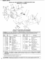
3-- PIVOT ASSEMBLY
Description
Plate-Lock
Screw Pan HD,
Shoulder M6
_:Spring-Torsion
* Screw Pan HD. 6-32 x 1/4
Indicator-Bevel
Pivot-Support
Bolt-Bevel
Washer 10 x 19x 1.8
Hardware Item--May
by Key Number
Key
No.
Part
No.
9
10
STD551137
141594-44
11
12
13
14
15
16
60047
816721
816666
816723
816863-2
818071
Description
&
* Lockwasher 3/8
Screw Soc HD. Cap
3/8-16 x 1-1/2
Washer .630x 1 x 1/32
Bolt-Pivot
Bolt-Stop
Nut Lock M16
Clamp-Bolt
Pivot
Be Purchased Locally.
1:See Mechanical Assembly Caution on page 29,
I_1_ WARNING:
These Items Are Important To The Safety Of This Tool. Do Not Substitute
Common Parts.
€_
t-,
29 cc
repair parts
PARTS LIST FOR CRAFTSMAN
10" COMPOUND
MODEL NO. 113.234600
/
MITER SAW
21
/
1
2O
18
19
1
3
16
12
15
7
/"
13
11
3O
repair parts
PARTS
LIST FOR CRAFTSMAN
10" COMPOUND
MODEL NO. 113.234600
Always order by Part Number--Not
FIGURE
Key
No.
1
2
3
4
5
6
7
8
9
Part
No.
507758
816706
STD511103
816708
816707
818962
STD852005
816755-2
507759
10
9-32668
11
816703
by Key Number
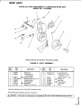
4. Blade & Blade Guard AsmJ;
Description
_
Key
NO.
Part
No.
Guard Asm.
Plate-Retainer
* Screw Pan HD 10-32 x 3/8
Spring
Lock-Spindle
Bushing Hex
* Lockwasher 5ram
12
13
14
15
816677
816711
60041
816333-1
16
17
507757
817144
Screw Pan HD.
Collar-Blade
SetM5 x 15
(Includes Key #13)
t 10-in. Chisel Tooth
Saw Blade
Scr. Hex Washer HD.
L.H, M8x 1.25
18
19
816811
817145
20
21
816818
816812
*Standard Hardware Item--May
MITER SAW
Description
:1:Spring-Guard
1:Guard-Lower
* Washer 13/64 x 7/16 x 1/32
Screw Pan HD. TY "-IT"
10-32 x 1/2
Lever Asm.-Actuator
Screw-Shoulder
1/4-20x 1/2
Bag-Dust
Screw-Shoulder
10-32 x 7/8
Sleeve-Rubber
Clamp-Bag
Be Purchased Locally.
$See following Mechanical Assembly Caution.
t Stock Item May Be Secured Through The Hardware Department Of Most Sears Retail Or Catalog Order
Houses.
I_
WARNING: These Items Are Important To The Safety Of This Tool. Do Not Substitute Common
Parts.
I
CAUTION: Mechanical assembly, to qualified service technician.
1. Wear approved eye protection when working with coil springs including spring, switch lock 816696.
2. Incorrect re-assembly of torsion spring 816671 can cause an unsafe condition because cutting head fails
to rise fully to stop, or because spring fails through over-stress.
3. Improper re-assembly of mechanisms controlling movement of lower guard 816711 can cause an unsafe
condition because guard fails to operate freely as cutting head is moved up and down; or because, with
cutting head up, manually rotated guard is not (lightly) restored to the closed position by guard spring
816677.
31
CARBIDE
SAFETY
TIPPED
INSTRUCTIONS
BLADES
& WARNINGS
OSHA required industrial
users to inspect tool prior to mounting
for cracks,
chipped
or bent teeth,
or cutting
edges that
are
not sharp. The tool must be completely
clean to allow proper
inspection.
See CFR § 1910.213
WOODWORKING
MACHINERY
REQUIREMENTS-ITEM
"All cracked saws shall be removed from service;'
S-7
Do not operate saw machine wit.hout proper saw blade guard in
place. Other important
instructions
and warnings regarding
your
safety are contained in saw machine owner's manual. If you do not
have such a manual, contact the machine manufacturer
to obtain
one before using the saw machine with this blade.
Carbide is a very hard but brittle material.
Care should be taken
while mounting,
using and storing
carbide
blades to prevent
accidental
damage.
Slight shocks,
such as striking
tip during
handling,
can seriously damage the blade. Foreign objects in the
workpiece, such as wire or nails, can also cause tips to crack or
break off.
Never use blade on saw
recoimnended
blade R.RM.
machine
that
will exceed
Always wear proper eye protection which complies
Standard Z87.1 when using any power tool.
maximum
with current
ANSI
Before using, Always:
• Visually examine blade and tips for cracks breakage, missing
or loose tips, or other damage.
DO NOT USE IF DAMAGE
IS SUSPECTED.
• Mount blade securely, in proper rotation direction.
• Never leave a running machine unattended.
FAILURE TO IIEED THESE INSTRUCTIONS
REGARDING
USE OF THIS
PRODUCT
SERIOUS
BODIIX INJURY.
AND _ARNINGS
CAN RESULT
IN
f
f
_AIRS
10-1NCH COMPOUND
MITER SAW
owner's
manual
SERVICE
MODEL NO.
113.234600
Now that you have purchased your 10-inch Compound
Miter
Saw, should a need ever exist for repair parts or service,
simply contact
any Sears Service Center and most Sears,
Roebuck
and Co. stores. Be sure to provide
all pertinent
facts when you call or visit.
The model number of your 10-inch Compound
Miter Saw
will be found on a plate attachment
to your saw, at the side
of the Miter Saw arm.
10" COMPOUND
MITER SAW
HOW TO ORDER
REPAIRPARTS
WHEN ORDERING REPAIR PARTS,ALWAYS GIVE THE FOLLOWING
INFORMATION:
PARTNUMBER
PARTDESCRIPTION
MODEL NUMBER
113.234600
NAME OF ITEM
!0 rr COMPOUND MITERSAW
All parts listed may be ordered from any Sears Service Center
and most Sears stores. If the parts you need are not stocked
locally, your order will be electronically
transmitted to a Sears
Repair Parts Distribution Center for handling.
....
Sold by SEARS, ROEBUCK AND CO., Chicago,
Part No. SP5404
Form No, SP5404-2
J
IL 60684 U.S.A.
Printed
in Taiwan
10/92