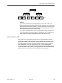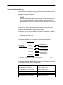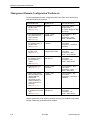
1
HOTWIRE DSLAM
FOR 8540 AND
8546 DSL CARDS
NETWORK CONFIGURATION GUIDE
Document No. 8000-A2-GB21-30
April 1998
Copyright 1998 Paradyne Corporation.
All rights reserved.
Printed in U.S.A.
Notice
This publication is protected by federal copyright law. No part of this publication may be copied or distributed,
transmitted, transcribed, stored in a retrieval system, or translated into any human or computer language in any form
or by any means, electronic, mechanical, magnetic, manual or otherwise, or disclosed to third parties without the
express written permission of Paradyne Corporation, 8545 126th Ave. N., Largo, FL 33773.
Paradyne Corporation makes no representation or warranties with respect to the contents hereof and specifically
disclaims any implied warranties of merchantability or fitness for a particular purpose. Further, Paradyne Corporation
reserves the right to revise this publication and to make changes from time to time in the contents hereof without
obligation of Paradyne Corporation to notify any person of such revision or changes.
Changes and enhancements to the product and to the information herein will be documented and issued as a new
release to this manual.
Warranty, Sales, and Service Information
Contact your local sales representative, service representative, or distributor directly for any help needed. For
additional information concerning warranty, sales, service, repair, installation, documentation, training, distributor
locations, or Paradyne worldwide office locations, use one of the following methods:
Via the Internet: Visit the Paradyne World Wide Web site at http://www.paradyne.com
Via Telephone: Call our automated call system to receive current information via fax or to speak with a
company representative.
— Within the U.S.A., call 1-800-870-2221
— Outside the U.S.A., call 1-727-530-2340
Trademarks
All products and services mentioned herein are the trademarks, service marks, registered trademarks or registered
service marks of their respective owners.
Printed on recycled paper
A
April 1998
8000-A2-GB21-30
Contents
About This Guide
H Document Purpose and Intended Audience . . . . . . . . . . . . . . . . . . . . . . . . . v
H Document Summary . . . . . . . . . . . . . . . . . . . . . . . . . . . . . . . . . . . . . . . . . . . . . vi
H Product-Related Documents . . . . . . . . . . . . . . . . . . . . . . . . . . . . . . . . . . . . . . vii
1
Introduction to the Hotwire DSLAM
H What is the Hotwire DSLAM? . . . . . . . . . . . . . . . . . . . . . . . . . . . . . . . . . . . . . 1-1
H Hotwire DSLAM Components . . . . . . . . . . . . . . . . . . . . . . . . . . . . . . . . . . . . . 1-4
Hotwire DSLAM Chassis . . . . . . . . . . . . . . . . . . . . . . . . . . . . . . . . . . . . . 1-4
MCC Card . . . . . . . . . . . . . . . . . . . . . . . . . . . . . . . . . . . . . . . . . . . . . . . . . . 1-6
DSL Cards . . . . . . . . . . . . . . . . . . . . . . . . . . . . . . . . . . . . . . . . . . . . . . . . . 1-6
H What is an RTU? . . . . . . . . . . . . . . . . . . . . . . . . . . . . . . . . . . . . . . . . . . . . . . . . 1-6
5170 RTU . . . . . . . . . . . . . . . . . . . . . . . . . . . . . . . . . . . . . . . . . . . . . . . . . . 1-7
5171 Remote PC NIC . . . . . . . . . . . . . . . . . . . . . . . . . . . . . . . . . . . . . . . . 1-8
5216 and 5246 RTUs . . . . . . . . . . . . . . . . . . . . . . . . . . . . . . . . . . . . . . . . 1-8
5446 RTU . . . . . . . . . . . . . . . . . . . . . . . . . . . . . . . . . . . . . . . . . . . . . . . . . . 1-10
5546 RTU . . . . . . . . . . . . . . . . . . . . . . . . . . . . . . . . . . . . . . . . . . . . . . . . . . 1-11
H Data Rates . . . . . . . . . . . . . . . . . . . . . . . . . . . . . . . . . . . . . . . . . . . . . . . . . . . . . 1-12
H Overview of the Hotwire DSLAM Network Model . . . . . . . . . . . . . . . . . . . . 1-12
H Understanding the Domain Types . . . . . . . . . . . . . . . . . . . . . . . . . . . . . . . . . 1-16
2
Service Domain Features
H Overview . . . . . . . . . . . . . . . . . . . . . . . . . . . . . . . . . . . . . . . . . . . . . . . . . . . . . . 2-1
H Protocols . . . . . . . . . . . . . . . . . . . . . . . . . . . . . . . . . . . . . . . . . . . . . . . . . . . . . . 2-1
H Proxy ARP (Theory of Operation) . . . . . . . . . . . . . . . . . . . . . . . . . . . . . . . . . 2-2
Scenario 1: Without Proxy ARP . . . . . . . . . . . . . . . . . . . . . . . . . . . . . . . 2-2
Scenario 2: With Proxy ARP . . . . . . . . . . . . . . . . . . . . . . . . . . . . . . . . . . 2-3
H Filtering . . . . . . . . . . . . . . . . . . . . . . . . . . . . . . . . . . . . . . . . . . . . . . . . . . . . . . . . 2-4
8000-A2-GB21-30
April 1998
i
Contents
3
Management Domain Features
H Overview . . . . . . . . . . . . . . . . . . . . . . . . . . . . . . . . . . . . . . . . . . . . . . . . . . . . . . 3-1
H Network Management Systems – SNMP and DCE Manager . . . . . . . . . . 3-1
H Applications for Management Domain . . . . . . . . . . . . . . . . . . . . . . . . . . . . . 3-2
Ping . . . . . . . . . . . . . . . . . . . . . . . . . . . . . . . . . . . . . . . . . . . . . . . . . . . . . . . 3-2
TraceRoute . . . . . . . . . . . . . . . . . . . . . . . . . . . . . . . . . . . . . . . . . . . . . . . . . 3-3
TFTP Client . . . . . . . . . . . . . . . . . . . . . . . . . . . . . . . . . . . . . . . . . . . . . . . . . 3-3
Telnet . . . . . . . . . . . . . . . . . . . . . . . . . . . . . . . . . . . . . . . . . . . . . . . . . . . . . . 3-3
4
Components of the Network Model
H Overview . . . . . . . . . . . . . . . . . . . . . . . . . . . . . . . . . . . . . . . . . . . . . . . . . . . . . . 4-1
H Service Domain Components . . . . . . . . . . . . . . . . . . . . . . . . . . . . . . . . . . . . . 4-1
Proxy ARP . . . . . . . . . . . . . . . . . . . . . . . . . . . . . . . . . . . . . . . . . . . . . . . . . 4-5
H Management Domain Components . . . . . . . . . . . . . . . . . . . . . . . . . . . . . . . . 4-7
Discovering Devices on the Network (Discovery) . . . . . . . . . . . . . . . . 4-8
MCC Card Proxy ARP . . . . . . . . . . . . . . . . . . . . . . . . . . . . . . . . . . . . . . . 4-9
5
IP Address Allocation
H Overview . . . . . . . . . . . . . . . . . . . . . . . . . . . . . . . . . . . . . . . . . . . . . . . . . . . . . . 5-1
H Port Naming Convention . . . . . . . . . . . . . . . . . . . . . . . . . . . . . . . . . . . . . . . . . 5-1
H Assigning IP Addresses . . . . . . . . . . . . . . . . . . . . . . . . . . . . . . . . . . . . . . . . . . 5-2
Host Addressing . . . . . . . . . . . . . . . . . . . . . . . . . . . . . . . . . . . . . . . . . . . . . 5-3
Structured Subnet Addressing . . . . . . . . . . . . . . . . . . . . . . . . . . . . . . . . 5-4
H Management IP Address Allocation . . . . . . . . . . . . . . . . . . . . . . . . . . . . . . . . 5-8
Peer IP Addresses . . . . . . . . . . . . . . . . . . . . . . . . . . . . . . . . . . . . . . . . . . . 5-9
H Service IP Address Allocation . . . . . . . . . . . . . . . . . . . . . . . . . . . . . . . . . . . . . 5-11
H Dynamic IP Addressing . . . . . . . . . . . . . . . . . . . . . . . . . . . . . . . . . . . . . . . . . . 5-12
H Recording Your Configuration Settings . . . . . . . . . . . . . . . . . . . . . . . . . . . . . 5-12
ii
April 1998
8000-A2-GB21-30
Contents
6
IP Routing
H Overview . . . . . . . . . . . . . . . . . . . . . . . . . . . . . . . . . . . . . . . . . . . . . . . . . . . . . . 6-1
H Routing Table . . . . . . . . . . . . . . . . . . . . . . . . . . . . . . . . . . . . . . . . . . . . . . . . . . . 6-1
H Static Routes for Static IP Addressing . . . . . . . . . . . . . . . . . . . . . . . . . . . . . 6-2
MCC Card Static Route Example . . . . . . . . . . . . . . . . . . . . . . . . . . . . . . 6-3
DSL Card Static Route Example . . . . . . . . . . . . . . . . . . . . . . . . . . . . . . . 6-4
H Dynamic Routes for Dynamic IP Addressing . . . . . . . . . . . . . . . . . . . . . . . . 6-5
How Does Dynamic IP Addressing Work? . . . . . . . . . . . . . . . . . . . . . . 6-6
H General DHCP Relay Agent Configuration . . . . . . . . . . . . . . . . . . . . . . . . . . 6-8
H Notes to the Authentication Server Administrator . . . . . . . . . . . . . . . . . . . . 6-9
RADIUS Authentication . . . . . . . . . . . . . . . . . . . . . . . . . . . . . . . . . . . . . . 6-9
XTACACS Authentication . . . . . . . . . . . . . . . . . . . . . . . . . . . . . . . . . . . . . 6-10
H Source-Based Routing . . . . . . . . . . . . . . . . . . . . . . . . . . . . . . . . . . . . . . . . . . . 6-10
Without Source-Based Routing . . . . . . . . . . . . . . . . . . . . . . . . . . . . . . . . 6-11
With Source-Based Routing . . . . . . . . . . . . . . . . . . . . . . . . . . . . . . . . . . . 6-12
7
IP Filtering
H Overview . . . . . . . . . . . . . . . . . . . . . . . . . . . . . . . . . . . . . . . . . . . . . . . . . . . . . . 7-1
H What is a Filter? . . . . . . . . . . . . . . . . . . . . . . . . . . . . . . . . . . . . . . . . . . . . . . . . 7-1
H Security Advantages . . . . . . . . . . . . . . . . . . . . . . . . . . . . . . . . . . . . . . . . . . . . 7-3
Management Traffic Leakage . . . . . . . . . . . . . . . . . . . . . . . . . . . . . . . . . 7-4
Service Security . . . . . . . . . . . . . . . . . . . . . . . . . . . . . . . . . . . . . . . . . . . . . 7-4
H Service Security Filtering Scenario . . . . . . . . . . . . . . . . . . . . . . . . . . . . . . . . 7-5
8
SNMP Agent
H Overview . . . . . . . . . . . . . . . . . . . . . . . . . . . . . . . . . . . . . . . . . . . . . . . . . . . . . . 8-1
H MIB Compliance . . . . . . . . . . . . . . . . . . . . . . . . . . . . . . . . . . . . . . . . . . . . . . . . 8-2
H Supported Traps . . . . . . . . . . . . . . . . . . . . . . . . . . . . . . . . . . . . . . . . . . . . . . . . 8-3
H General SNMP Agent Configuration . . . . . . . . . . . . . . . . . . . . . . . . . . . . . . . 8-4
9
Packet Walk-Throughs
H Overview . . . . . . . . . . . . . . . . . . . . . . . . . . . . . . . . . . . . . . . . . . . . . . . . . . . . . . 9-1
H Packet Walk-Through Using an 8540 DSL Card . . . . . . . . . . . . . . . . . . . . . 9-1
Service Domain Packet Walk-Through . . . . . . . . . . . . . . . . . . . . . . . . . 9-1
Management Domain Packet Walk-Through . . . . . . . . . . . . . . . . . . . . 9-3
H Packet Walk-Through Using an 8546 DSL Card . . . . . . . . . . . . . . . . . . . . . 9-3
Service Domain Packet Walk-Through . . . . . . . . . . . . . . . . . . . . . . . . . 9-3
Management Domain Packet Walk-Through . . . . . . . . . . . . . . . . . . . . 9-5
8000-A2-GB21-30
April 1998
iii
Contents
A
Network Configuration Worksheets
H Overview . . . . . . . . . . . . . . . . . . . . . . . . . . . . . . . . . . . . . . . . . . . . . . . . . . . . . . A-1
H Summarizing the Network Configuration . . . . . . . . . . . . . . . . . . . . . . . . . . . A-1
H Management Domain Configuration Worksheets . . . . . . . . . . . . . . . . . . . . A-2
TASK 1: Assign an IP Address to the MCC Card . . . . . . . . . . . . . . . . . A-3
TASK 2: Clear NVRAM . . . . . . . . . . . . . . . . . . . . . . . . . . . . . . . . . . . . . . . A-5
TASK 3: Assign an IP Address to the Backplane (s1b) . . . . . . . . . . . . A-6
TASK 4: Assign IP Addresses to the DSL Cards . . . . . . . . . . . . . . . . . A-7
TASK 5: Create a Default Route . . . . . . . . . . . . . . . . . . . . . . . . . . . . . . .
TASK 6: Reset the MCC Card . . . . . . . . . . . . . . . . . . . . . . . . . . . . . . . . .
TASK 7: (When Using an 8546 DSL Card) Configure the
Hotwire 5446 RTU Management Domain IP Addresses . . . . . . . . . . .
TASK 8: Create a Static Route to an NMS . . . . . . . . . . . . . . . . . . . . . .
H Service Domain Configuration Worksheets . . . . . . . . . . . . . . . . . . . . . . . . .
TASK 1: Assign IP Addresses to the DSL Card LAN
Interface (e1a) . . . . . . . . . . . . . . . . . . . . . . . . . . . . . . . . . . . . . . . . . . . . . .
TASK 2: Reset the DSL Card . . . . . . . . . . . . . . . . . . . . . . . . . . . . . . . . .
TASK 3: Create a Default Route or Source Route . . . . . . . . . . . . . . . .
TASK 4: Select RTU Type . . . . . . . . . . . . . . . . . . . . . . . . . . . . . . . . . . . .
TASK 5: Configure RTU Information . . . . . . . . . . . . . . . . . . . . . . . . . . .
TASK 6: Add or remove a static route to the RTU . . . . . . . . . . . . . . . .
TASK 7: Define DHCP Relay Features to Enable Dynamic
IP Address Configuration . . . . . . . . . . . . . . . . . . . . . . . . . . . . . . . . . . . . .
B
A-12
A-14
A-16
A-17
A-19
A-20
A-22
A-24
A-26
A-28
IP Filtering Configuration Worksheets
H Overview . . . . . . . . . . . . . . . . . . . . . . . . . . . . . . . . . . . . . . . . . . . . . . . . . . . . . .
H Summarizing How to Define a Filter . . . . . . . . . . . . . . . . . . . . . . . . . . . . . . .
H Filtering Configuration Worksheets . . . . . . . . . . . . . . . . . . . . . . . . . . . . . . . .
Defining the Filter and Rules . . . . . . . . . . . . . . . . . . . . . . . . . . . . . . . . . .
Binding the Filter . . . . . . . . . . . . . . . . . . . . . . . . . . . . . . . . . . . . . . . . . . . .
C
A-9
A-11
B-1
B-1
B-3
B-3
B-7
SNMP Configuration Worksheets
H Overview . . . . . . . . . . . . . . . . . . . . . . . . . . . . . . . . . . . . . . . . . . . . . . . . . . . . . .
H Summarizing the General SNMP Agent Configuration . . . . . . . . . . . . . . .
H SNMP Agent Configuration Worksheets . . . . . . . . . . . . . . . . . . . . . . . . . . . .
Defining a Community and Enabling Traps . . . . . . . . . . . . . . . . . . . . . .
Preventing Unauthorized Access . . . . . . . . . . . . . . . . . . . . . . . . . . . . . .
C-1
C-1
C-2
C-2
C-5
Glossary
Index
iv
April 1998
8000-A2-GB21-30
About This Guide
Document Purpose and Intended Audience
This guide describes the Hotwire Digital Subscriber Line Access Multiplexer
(DSLAM), its internetworking features, and how it supports the Hotwire 8540 and
8546 Digital Subscriber Line (DSL) cards. It also provides information on what
you need to know before planning your network. Use this guide to:
H
Obtain a basic understanding of the Hotwire DSLAM
H
Understand how the DSLAM operates within the network
H
Understand the network model, management domain, and service domain
H
Understand how to allocate Internet Protocol (IP) addresses
H
Understand dynamic IP addressing
NOTE:
The DSL Sourcebook, written by Paradyne Corporation, is about DSL
technology and opportunities. Read the DSL Sourcebook for the what, how,
and why of DSL-based service deployment. The book is available by calling
1-800-PARADYNE.
This guide is intended for network planners, network administrators, and network
maintainers. It is assumed that you have a basic understanding of
internetworking protocols and their features. Specifically, you should have a basic
familiarity with Simple Network Management Protocol (SNMP), Network
Management Systems (NMSs), and the following internetworking concepts:
8000-A2-GB21-30
H
TCP/IP applications
H
IP and subnet addressing
H
IP routing (also referred to as IP forwarding)
April 1998
v
About This xxxx
Document Summary
vi
Section
Description
Chapter 1
Introduction to the Hotwire DSLAM. Provides an
overview of the Hotwire DSLAM and its components. It
also briefly describes the network model and the
domain types.
Chapter 2
Service Domain Features. Describes the features that
are supported in the service domain.
Chapter 3
Management Domain Features. Describes the features
that are supported in the management domain.
Chapter 4
Components of the Network Model. Describes the
components of the service and management domains.
These domains comprise the network model.
Chapter 5
IP Address Allocation. Describes the IP address
allocation schemes for the components that make up
the network model. With these allocation schemes, IP
addresses can be assigned statically or dynamically. It
also describes the naming convention used for the
Hotwire DSLAM system ports.
Chapter 6
IP Routing. Provides information and examples of
destination-based routing (static and dynamic routes)
and source-based routing.
Chapter 7
IP Filtering. Describes IP filtering advantages and
scenarios.
Chapter 8
SNMP Agent. Describes the SNMP agent configuration
(community configuration and trap configuration).
Chapter 9
Packet Walk-Throughs. Provides examples of how
data packets are routed through the service and
management domains.
Appendix A
Network Configuration Worksheets. Provides
worksheets to record your configuration settings.
Appendix B
IP Filtering Configuration Worksheets. Provides
worksheets to help you define a filter for a specific
interface on an MCC or DSL card.
Appendix C
SNMP Configuration Worksheets. Provides worksheets
to help you set up community names and
enable/disable the generation of alarms.
Glossary
Defines acronyms and terms used in this document.
Index
Lists key terms, acronyms, concepts, and sections in
alphabetical order.
April 1998
8000-A2-GB21-30
About This Guide
Product-Related Documents
8000-A2-GB21-30
Document Number
Document Title
5020-A2-GN10
Hotwire 5020 POTS Splitter Central Office
Installation Instructions
5030-A2-GN10
Hotwire 5030 POTS Splitter Customer Premises
Installation Instructions
5034-A2-GN10
Hotwire 5034 Indoor POTS Splitter Customer
Premises Installation Instructions
5100-A2-GB21
Hotwire 5171 Remote PC Network Interface Card
User’s Guide
5100-A2-GB22
Hotwire 5170 Remote Termination Unit User’s Guide
5216-A2-GN10
Hotwire 5216 Remote Termination Unit (RTU)
Customer Premises Installation Instructions
5246-A2-GN10
Hotwire 5246 Remote Termination Unit (RTU)
Customer Premises Installation Instructions
5446-A2-GN10
Hotwire 5446 Remote Termination Unit (RTU)
Customer Premises Installation Instructions
5546-A2-GN10
Hotwire 5546 Remote Termination Unit (RTU)
Customer Premises Installation Instructions
7700-A2-GB23
OpenLane DCE Manager for HP OpenView for
Windows User’s Guide
7800-A2-GB26
OpenLane DCE Manager User’s Guide
8000-A2-GB20
Hotwire DSLAM for 8540 and 8546 DSL Cards
User’s Guide
8000-A2-GB24
Hotwire DSLAM Configuration for 8540 and 8546
DSL Cards Startup Instructions
8000-A2-GB25
Hotwire 8100/8200 Interworking Packet Concentrator
(IPC) Network Configuration Guide
8000-A2-GB29
Hotwire Management Communications Controller
(MCC) Card User’s Guide
8000-A2-GB90
Hotwire 8100/8200 Interworking Packet Concentrator
(IPC) User’s Guide
8000-A2-GN11
Hotwire Management Communications Controller
(MCC) Card Installation Instructions
8540-A2-GN10
Hotwire 8540 Digital Subscriber Line (DSL) Card
Installation Instructions
8546-A2-GN10
Hotwire 8546 Digital Subscriber Line (DSL) Card
Installation Instructions
April 1998
vii
About This Guide
Document Number
Document Title
8600-A2-GN20
Hotwire 8600 Digital Subscriber Line Access
Multiplexer (DSLAM) Installation Guide
8800-A2-GN21
Hotwire 8800 Digital Subscriber Line Access
Multiplexer (DSLAM) Installation Guide
Contact your sales or service representative to order additional product
documentation.
Paradyne documents are also available on the World Wide Web at:
http://www.paradyne.com
Select Service & Support → Technical Manuals
viii
April 1998
8000-A2-GB21-30
Introduction to the Hotwire
DSLAM
1
What is the Hotwire DSLAM?
The Hotwire Digital Subscriber Line Access Multiplexer (DSLAM) is a
multiservices DSL platform that provides high-speed Internet or Intranet access
over traditional twisted-pair telephone wiring. The DSLAM chassis houses DSL
cards that interoperate with multiple types of Hotwire Remote Termination Units
(RTU) to deliver applications at multimegabit speeds in support of packet services
over a Digital Subscriber Line (DSL) link.
High-speed service traffic types from the DSL links are groomed and then
concentrated for efficient forwarding to backbone routers. By enabling very high
speeds using DSL technology and then concentrating Internet Protocol (IP)
traffic, greater performance is realized. Backbone service nodes can be placed
deeper into the network, dramatically improving the economics of service
provisioning while taking advantage of the substantial speed increases of DSL.
When used in combination with a Hotwire 8200 Interworking Packet Concentrator
(IPC), the Hotwire DSLAM provides high-speed IP service concentration over a
wide array of Local Area Network (LAN) architectures as well as an
Asynchronous Transfer Mode (ATM) interface to Wide Area Networks (WANs).
In addition, the Hotwire DSLAM with a Hotwire RTU can be multiplexed with Plain
Old Telephone Service (POTS) over the same copper line providing simultaneous
usage of POTS and digital applications to separate locations. That is, the optional
POTS splitters allow simultaneous voice and data connections over a standard
telephone line.
NOTE:
If you would like more information on DSL-based services, applications, and
network deployment, refer to Paradyne’s DSL Sourcebook. The book may be
ordered by calling 1-800-PARADYNE.
8000-A2-GB21-30
April 1998
1-1
Introduction to the Hotwire DSLAM
The following illustration shows a high-level view of a Hotwire configuration:
NOTE:
The cable connection from a DSL card to a Main Distribution Frame (MDF)
can either be a direct connection to the MDF or a connection through a POTS
splitter to an MDF, but not both. Refer to the appropriate Hotwire DSLAM
Installation Guide for more information.
Central Office (CO)
Network
Service
Provider
Customer Premises (CP)
Hotwire
8200
IPC
Data
Interface
Ethernet
DSL
CARD
DSLAM
MDF
POTS
CO
POTS
Splitter
Optional
RTU
POTS/DSL
CO
Switch
CP
POTS
Splitter
Voice
Interface
Optional
Legend: DSL - Digital Subscriber Line
RTU - Remote Termination Unit
MDF - Main Distribution Frame POTS - Plain Old Telephone Service
IPC - Interworking Packet Concentrator
97-15674-01
The Hotwire DSLAM can be configured to work with multiple types of RTUs
installed at the customer end of the local telephone loop. RTUs terminate the
DSL line and allow users at remote locations to access Network Service
Providers (NSPs) or corporate networks by means of the DSL phone line.
When using an 8540 DSL card in the DSLAM, the DSLAM can be configured to
interoperate with any one of the following RADSL RTUs on each of its four DSL
ports:
1-2
H
5170 RTU – Operates at speeds up to 7 Mbps with a simple bridge that
supports up to 32 end-user systems.
H
5171 Remote PC Network Interface Card (NIC) – Operates at speeds up to
2.5 Mbps supporting a single user’s PC.
H
5216 RTU – Operates at speeds up to 1.28 Mbps supporting a single user.
H
5246 RTU – Operates at speeds up to 7 Mbps with a transparent learning
bridge that supports up to 32 end-user systems.
April 1998
8000-A2-GB21-30
Introduction to the Hotwire DSLAM
When using an 8546 DSL card with the 5446 RTU in the DSLAM, the DSLAM
can be configured to interoperate with up to four 5446 RTUs. The 5446 RTU
operates as an IP forwarder at speeds up to 7 Mbps. This RTU supports up to 32
end-user systems with individual IP addresses or subnets.
When using an 8546 DSL card with the 5546 RTU in the DSLAM, the DSLAM
can be configured to allow an end-user to utilize an external router with a
V.35/EIA-530 interface. The 5546 RTU operates at speeds up to 7 Mbps
supporting up to 32 hosts or subnets behind the external router connected to the
5546 RTU. As most serial interface speeds are set at the T1/E1 rate, the 5546
operational speed should be set accordingly.
The following illustration shows a Hotwire network configuration from the
8800 DSLAM to multiple RTUs. (Stacked 8600 DSLAMs can also be used in
place of an 8800 DSLAM.)
5546 RTU
V.35 or EIA-530
TM
PWR
ALM
TST
DSL
ETHERNET
TM
Router
ES 1
5446 RTU
10BT
TM
PWR
ALM
TST
DSL
ETHERNET
TM
ES 32
Hub
ES 1
5170 RTU
TM
PWR
ALM
TST
DSL
ETHERNET
TM
10BT Hub or
Router
ES 32
8546
DSL
Card
8540
DSL
Card
PC With
Internal
5171 PC NIC
5246 RTU
POWER
A
B
ALARMS
Fan Major Minor
10BT
TM
PWR
ALM
TST
DSL
ETHERNET
ES 1
Hub
TM
ES 32
8800 DSLAM
ES 1
5246 RTU
8546
DSL
Card
8540
DSL
Card
TM
PWR
ALM
TST
DSL
ETHERNET
TM
10BT
Hub or
Router
ES 32
5216 RTU
TM
PWR
ALM
TST
DSL
ETHERNET
TM
ES = End-user System
RTU = Remote Termination Unit
10BT= 10BaseT
NIC = Network Interface Card
8000-A2-GB21-30
April 1998
97-15793
1-3
Introduction to the Hotwire DSLAM
Hotwire DSLAM Components
The Hotwire DSLAM resides in a central office (CO) or wire center. It consists of
the following components:
H
Hotwire DSLAM chassis
H
MCC card
H
DSL cards
In addition, optional POTS splitters can be installed at the CO. For information
about a CO POTS Splitter, see the Hotwire 5020 POTS Splitter Central Office
Installation Instructions.
Hotwire DSLAM Chassis
There are two types of chassis:
H
Hotwire 8600 DSLAM chassis
..
RADSL
8546
RADSL
8546
4
3
D
ol
C
X
R
8000
D
RT
2
SL
1
PO
ol
C
X
ET
N
ALM
MCC
4
3
1
PO
SL
2
RT
ET
ol
C
N
X
TX
ER
H
ET
1
B
.
.
3
2
1
A
STACK
POSITION
LINE
LAN/WAN SLOT
MANAGEMENT
PWR
FAN
4 5 6
3
2
A
R
H
ET
ET
N
DC FUSES
T4A, MIN. 48V
48VDC CLASS 2 OR
LIMITED PWR SOURCE
TX
H
ER
EM
K
Alr
m
Te
st
O
ST
B A B
ET
A
AC
INPUT
TX
ER
EM
K
Alr
m
Te
st
O
ST
SY
ESD
RTN
SY
48V
R
K
Alr
m
Te
st
O
SY
ST
EM
The Hotwire 8600 DSLAM is a low-cost alternative to the Hotwire
8800 DSLAM. The 8600 DSLAM is an independent, standalone system. A
stackable design provides for up to six 8600 DSLAMs to share management
access through a single MCC card. In a stacked configuration, the first or
base chassis is equipped with an MCC card in Slot 1, leaving Slots 2 and 3
available for up to two DSL cards with a maximum of eight DSL ports. Each
additional chassis houses up to three DSL cards. This stacking capability
allows you to incrementally expand your DSL access service.
B
IN
OUT
SERIAL
MCC
1
2
3
98-15350-02
For more information about the Hotwire 8600 DSLAM chassis, see the
Hotwire 8600 Digital Subscriber Line Access Multiplexer (DSLAM) Installation
Guide.
1-4
April 1998
8000-A2-GB21-30
Introduction to the Hotwire DSLAM
H
Hotwire 8800 DSLAM chassis
The Hotwire 8800 DSLAM is a 20-slot chassis designed to house up to
18 DSL cards and one MCC card. (The remaining slot is reserved for future
use.) The Hotwire 8800 DSLAM chassis requires one MCC card and at least
one DSL card.
POWER
A
B
ALARMS
Fan Major Minor
SYST
SYST
EM
EM
OK
OK
Alm
Alm
Test
Test
ETHE
RNET
ETHE
RNET
TX
TX
RX
RX
Coll
DSL
Coll
PORT
1
2
3
4
RADSL
MCC
-48V INPUT
SLOTS 13-18
2
4
6
8
1
3
5
7
LAN/WAN SLOT
10
14
12
16
18
15
17
20
MGT
SERIAL
FR GND
RET (B)
SLOTS 1 - 6
RET (A)
LINES
-48V (B)
SLOTS 7-12
-48V (A)
Interface
Module
11
9
LAN/WAN SLOT
13
19
MGT
10BT
ALARM
Ground
Lug
98-15280-02
For information about the Hotwire 8800 DSLAM chassis, see the Hotwire
8800 Digital Subscriber Line Access Multiplexer (DSLAM) Installation Guide.
8000-A2-GB21-30
April 1998
1-5
Introduction to the Hotwire DSLAM
MCC Card
The MCC card is a single resource in the Hotwire DSLAM that provides
consolidated management access for the DSL cards and the Hotwire RTU from
any one of the following:
H
SNMP management systems, such as HP OpenView with Paradyne’s
OpenLanet DCE Manager (via the MCC card’s Ethernet port),
H
Remote telnet sessions (via the MCC card’s Ethernet port),
H
Local asynchronous terminal (via the MCC card’s VT100 serial port), or
H
Remote asynchronous terminal connected to a modem (via the MCC card’s
serial port).
The MCC card performs alarm monitoring of the Hotwire DSL cards, the DSLAM
power and cooling systems, and interfaces to the CO alarm system. It also
interfaces with external managers and servers (e.g., Trivial File Transfer Protocol
servers) for system configuration and management.
DSL Cards
Each 8540 or 8546 DSL card in the Hotwire DSLAM chassis contains four DSL
ports with on-board IP packet forwarding functionality. The outputs of the four
DSL ports are combined onto one 10BaseT interface for connecting to the
Internet or Intranet by means of the Network Access Provider’s network.
For a list of the supported features of the 8540 and 8546 DSL cards, see the
Hotwire DSLAM for 8540 and 8546 DSL Cards User’s Guide.
What is an RTU?
A Hotwire Remote Termination Unit (RTU) resides at the customer premises. The
RTU connects to the local loop to provide high-speed connectivity to the Hotwire
DSLAM. In addition, the RTU and your telephone can function simultaneously
over the same pair of copper wires when a POTS splitter is used at both ends of
the local loop. The POTS splitter filters out the DSL signal and allows the POTS
frequencies to pass through.
If you have an . . .
Your DSL card interoperates with a . . .
8540 DSL Card
5170 RTU
5171 Remote PC NIC
5216 RTU
5246 RTU
8546 DSL Card
5446 RTU
5546 RTU
The following sections describe these RTUs.
1-6
April 1998
8000-A2-GB21-30
Introduction to the Hotwire DSLAM
5170 RTU
The Hotwire 5170 RTU is a standalone unit designed for the home-office users
with a LAN. The RTU communicates with any computer equipment or router
using its Ethernet network interface card (NIC).
Control of the 5170 RTU is supplied by a windows-based diagnostics utility which
enables users to check RTU status, network transmission status, and run
diagnostic tests.
You can connect the 5170 RTU directly to your PC using an 8-pin modular
Ethernet cable.
The following illustration shows the Hotwire 5170 RTU with its 10BaseT interface
connected to multiple end-user systems (typically a PC with a LAN card).
End-user
System 1
Optional
POTS
POTS
Splitter
POTS
POTS/DSL
NID
From Network
Access Provider
DSL
End-user
System 2
5170
RTU
10BaseT
HUB
.
.
.
NID = Network Interface Device
End-user
System 32
97-15455c
For more information about the Hotwire 5170 RTU, see the Hotwire
5170 Remote Termination Unit User’s Guide.
8000-A2-GB21-30
April 1998
1-7
Introduction to the Hotwire DSLAM
5171 Remote PC NIC
The Hotwire 5171 PC Network Interface Card (NIC) is a 16-bit ISA, add-on card
with a 6-pin telephone modular jack connector used for the DSL network
connection. The 5171 PC NIC edge connector plugs into a 16-bit expansion slot
in an IBM-compatible 80486 (or higher) system board and conforms to ISA bus
standards.
The following illustration shows a PC with an internal Hotwire 5171 PC NIC.
Optional
POTS
POTS
Splitter
POTS
POTS/DSL
NID
From Network
Access Provider
PC with Internal
Hotwire 5171 PC
NIC
DSL
NID = Network Interface Device
98-15713-01
For more information about the Hotwire 5171 Remote PC NIC, see the Hotwire
5171 Remote PC Network Interface Card User’s Guide.
5216 and 5246 RTUs
The Hotwire 5216 and 5246 RTUs are each composed of a DSL modem and a
bridge.
The Hotwire 5216 RTU is designed for home office/residential applications and
supports a single end user system. The 5216 RTU supports limited DSL line
rates.
The following illustration shows the Hotwire 5216 RTU with its 10BaseT interface
connected directly to an end-user system (typically a PC or workstation with a
LAN card).
Optional
POTS
POTS
Splitter
POTS
POTS/DSL
NID
From Network
Access Provider
DSL
NID = Network Interface Device
1-8
April 1998
5216
or
5246
RTU
End-user
System
10BaseT
97-15455a
8000-A2-GB21-30
Introduction to the Hotwire DSLAM
The Hotwire 5246 RTU is designed for small office or home office (SOHO)
applications and supports up to 32 end-user systems with a LAN. The Hotwire
5246 supports full speed DSL line rates and filters local LAN traffic from
traversing the DSL link by incorporating learning bridge functionality.
The following illustration shows the 5246 RTU with its 10BaseT interface
connected to multiple end-user systems (typically a PC or workstation with a LAN
card) via an Ethernet 10BaseT hub.
End-user
System 1
Optional
POTS
POTS
Splitter
POTS
POTS/DSL
NID
From Network
Access Provider
DSL
End-user
System 2
5246
RTU
10BaseT
HUB
.
.
.
NID = Network Interface Device
End-user
System 32
97-15456a
For more information about these RTUs, see the Hotwire 5216 Remote
Termination Unit (RTU) Customer Premises Installation Instructions and the
Hotwire 5246 Remote Termination Unit (RTU) Customer Premises Installation
Instructions.
8000-A2-GB21-30
April 1998
1-9
Introduction to the Hotwire DSLAM
5446 RTU
The Hotwire 5446 RTU is composed of a DSL modem supporting full speed DSL
line rates and an IP forwarder that can support multiple end-user systems.
The 5446 RTU can be connected directly to an end-user system or to multiple
end-user systems via an Ethernet (10BaseT) hub.
The following illustration shows the Hotwire 5446 RTU with its 10BaseT interface
connected directly to an end-user system (typically a PC or workstation with a
LAN card) with a crossover cable:
Optional
POTS
POTS
Splitter
POTS
POTS/DSL
NID
From Network
Access Provider
DSL
NID = Network Interface Device
End-user
System
5446
RTU
10BaseT
97-15455b
A 5446 RTU supports multiple service domains and can be configured with up to
four IP subnets. Each of the four IP subnets can be comprised of multiple users
by appropriately sizing the respective IP subnet.
In addition, each 5446 RTU supports up to 32 end-user systems that dynamically
acquire their IP addresses or have static IP addresses. The Dynamic Host
Configuration Protocol (DHCP) is used for dynamic addressing. In both cases
(dynamic and static), these 32 end-user systems must be in one of the configured
IP subnets.
The following illustration shows a Hotwire 5446 RTU with its10BaseT interface
connected to multiple end-user systems (typically a PC or workstation with a LAN
card) via an Ethernet (10BaseT) hub.
1-10
April 1998
8000-A2-GB21-30
Introduction to the Hotwire DSLAM
End-user
System 1
Optional
POTS
POTS
Splitter
POTS
POTS/DSL
NID
From Network
Access Provider
DSL
End-user
System 2
5446
RTU
10BaseT
HUB
.
.
.
NID = Network Interface Device
End-user
System 32
97-15456b
For more information about the 5446 RTU, see the Hotwire 5446 Remote
Termination Unit (RTU) Customer Premises Installation Instructions.
5546 RTU
The Hotwire 5546 RTU is composed of a DSL modem port and a frame forwarder
that connects to an end-user router with a V.35/EIA-530 interface using PPP
protocol.
The 5546 RTU does not need an IP address, so therefore an IP address is not
injected. In addition, up to 32 hosts or subnets behind the external router can be
connected. The 5546 may be configured via a VT-100 console connected to the
RTU console port.
Optional
POTS
POTS
Splitter
POTS
POTS/DSL
NID
From Network
Access Provider
DSL
NID = Network Interface Device
8000-A2-GB21-30
April 1998
5546
RTU
V.35 or EIA-530 Router
97-15794
1-11
Introduction to the Hotwire DSLAM
Data Rates
The Hotwire DSL card employs Rate Adaptive Digital Subscriber Line (RADSL)
devices based on Carrierless Amplitude & Phase (CAP) technology. The RADSL
speed is asymmetric. This means that the downstream rate (from the DSLAM to
the RTU) is faster than the upstream rate (from the RTU to the DSLAM).
You can manually set the speed (providing the line you are using can support the
specified speed) or set the mode to rate adaptive. When the mode is set to rate
adaptive, the Hotwire DSLAM determines the line speed during the initial
handshaking session between the DSLAM and the RTU based on the local loop
length, the amount of noise on the loop, and the user-configurable upper and
lower speed limits.
The following are the maximum upstream and downstream data rates:
H
Maximum upstream data rate: 1088 kbps (1.088 Mbps)
H
Maximum downstream data rate: 7168 kbps (7.168 Mbps)
Data rates and data transmission distances vary depending on existing telephone
line conditions (i.e., the DSL cards measure performance during operation and
can adjust the upstream or downstream rate to match changing local loop
characteristics because of temperature, humidity, or electrical interference). Also,
the maximum data rate will be dependent on the RTU in use.
For a complete listing of the DSL card data rates and information on how to set
the line speed, see Chapter 5, DSL Card Configuration, of the Hotwire DSLAM for
8540 and 8546 DSL Cards User’s Guide.
Overview of the Hotwire DSLAM
Network Model
The Hotwire DSLAM and the Hotwire RTUs provide high-speed connectivity to
the Internet, corporation, or other network service from the end-user system.
The Hotwire DSLAM network model can be implemented in a number of ways.
For example:
1-12
H
A Small Office/Home Office (SOHO) implementation with one or more users
connected to a LAN needing high-speed connectivity to an Internet Service
Provider (ISP).
H
A SOHO implementation with one or more users connected to a LAN needing
high-speed connectivity to the corporate LAN or Intranet.
H
A campus implementation needing internetworking between several sites,
each with a LAN.
April 1998
8000-A2-GB21-30
Introduction to the Hotwire DSLAM
The network model for these examples can be partitioned into the following
building blocks:
H
Network Service Provider (NSP)
H
Network Access Provider (NAP)
H
Service Subscriber
Network
Service
Provider
Network
Access
Provider
Service
Subscriber
97-15457
The following illustration shows a detailed view of the network model:
Network Service Provider
ISP Router
Network Access Provider
Wire
Center
Access to
Point-ofPresence
RTU
WAN
Wire
Center
Access to
Point-ofPresence
Internet
Service Subscriber
RTU
Wire Center
Router
Corporate
Intranet
RTU
WAN-C
(Router or
VLAN Switch)
DSLAM
DSL
RTU
RTU
97-15499-02
8000-A2-GB21-30
April 1998
1-13
Introduction to the Hotwire DSLAM
H
The Service Subscriber is the user (or set of users) that has contracted to
receive networking services (e.g., Internet access, remote LAN access) for
the end-user system from one or more Network Service Providers (NSPs).
Service Subscribers may be:
— Residential users connected to public network services (e.g., the Internet)
— Work-at-home users connected to their corporate Intranet LAN
— Commercial users at corporate locations (e.g., branch offices) connected
by a LAN to other corporate locations or connected to public network
services
RTUs must be installed at the customer premises to provide the Service
Subscriber access by way of DSL to any of the above services.
H
The Network Access Provider (NAP) is typically the network provider (e.g.,
a Regional Bell Operating Company, an Alternate Local Exchange Carrier)
that has access to the copper twisted pairs over which the DSL-based
service operate. The NAP provides a transit network service permitting
connection of service subscribers to NSPs.
Typically, the NAP network is organized into three components:
— Wire center
The wire center is usually a local serving office where the wiring from the
service subscribers is terminated on the Hotwire DSLAM. This could be a
CO.
— Wide Area Network (WAN)
The WAN concentrates and switches data traffic from multiple wire
centers to one or more Regional Centers where service providers have
access to the network.
— Regional center
The NSP’s Point-of-Presence (POP) is the access point to the NAP
network for an NSP and is located at the regional center. The connection
from the NAP to the NSP network is typically across a WAN connection
to the NSP router at the regional center. This router acts as a next-hop
location to the NSP’s network.
H
1-14
The Network Service Providers (NSPs) can be either public access
providers to the Internet (i.e., Internet Service Providers) or private access
providers to corporate LANs, providing services based on the Internet
Protocol (IP). In some cases, the NSP and the NAP can be a single
organization.
April 1998
8000-A2-GB21-30
Introduction to the Hotwire DSLAM
One or more Hotwire DSLAMs are connected to a Wide Area Network
Concentrator (WAN-C) via a LAN. The WAN-C concentrates data traffic from one
or more DSLAMs into facilities providing access to the WAN. The WAN-C can be
either a router (a layer 3 networking device) or a VLAN switch (a layer 2
networking device).
H
If WAN-C is a router, the WAN must be a routed IP network (i.e., a network
of interconnected IP routers).
In this case:
— The router at the wire center is required to support routing policies which
permit packets arriving from the local DSLAMs to be routed based on the
service subscriber source IP address. The packets are routed to the
subscribed service providers’ POP based on the source IP address.
— The routing tables in the DSLAM are configured such that the next-hop
router is the IP address of the wire center router for all authorized
subscriber IP source addresses. (See the discussion on source-based
routing in Chapter 6, IP Routing.)
In addition, the router at the regional center may need to participate in an
exterior gateway protocol, such as the Border Gateway Protocol, to
exchange routing information between the NSP and NAP routing
networks.
— Packets flowing from the NSP network to the end-user systems are
routed within the NAP network based on the packet destination IP
address.
H
If WAN-C is a VLAN switch, the WAN must be a layer 2 switching network
supporting a Virtual LAN overlay.
In this case:
— Each NSP would be a member of a different Virtual LAN.
— The VLAN switch at the wire center would support either port-based
VLAN switching (i.e., switching all MAC frames received on a specific
port to a specific NSP VLAN on the WAN) or port-based VLAN switching
with MAC-based attributes (i.e., switching frames received on a specific
port to a specific NSP VLAN on the WAN based on the destination MAC
address) for packets sent from the DSLAMs.
— The router at the NSP premises would either be front ended by a VLAN
switch or have an integrated VLAN card that supports protocols
consistent with the wire center VLAN switch (e.g., ATM Forum LAN
Emulation Protocol).
— The routing tables in the DSLAM are configured such that the next-hop
address field points to the IP address of the NSP premises router for all
authorized subscriber IP source addresses. (See the discussion on
source-based routing in Chapter 6, IP Routing.)
8000-A2-GB21-30
April 1998
1-15
Introduction to the Hotwire DSLAM
— A different next-hop router is specified for each NSP address domain in
contrast to the routed network case where a single next-hop router was
specified for all NSP domains. If the DSLAM does not know the MAC
address of the NSP premises router, it uses ARP to obtain the MAC
address from the NSP premises router prior to forwarding the packet (i.e.,
the wire center VLAN switch forwards an ARP request over the WAN to
the NSP router).
— Packets flowing from the NSP network to the subscribers are routed to
the subscriber based on the destination IP address of the subscriber as is
most common for IP-routed networks. In this case, the LAN on which the
DSLAM resides appears to be part of a local subnet connected directly to
the NSP premises router. If the NSP router does not know the MAC
address of the subscriber, it uses ARP to obtain the MAC address from
the DSLAM that acts as a proxy for the subscriber. (See the discussion
on proxy ARP in Chapter 2, Service Domain Features.)
Understanding the Domain Types
Functionally, the Hotwire DSLAM network model can be divided into:
H
Features supporting customers
Features integral to supporting customers are the DSL cards and Hotwire
RTUs.
H
Features supporting overall system management
The central point of access for overall system management is the MCC card.
However, the features integral to supporting overall system management are
also distributed throughout the Hotwire DSLAM and the Hotwire RTUs.
To monitor and control the operation of the overall system, the IP addresses of
the Hotwire DSLAM and the Hotwire RTU must be partitioned into two distinct
domains.
H
Service domain(s)
The service domain (also known as the NSP domain) resides in a mutually
exclusive domain from that of the management domain. (There should be
one service domain for each NSP served by the Hotwire DSLAM.) One
service domain encompasses an NSP and all of the end-user systems that
subscribe to that NSP.
For more information about the service domain, its features and components,
see Chapter 2, Service Domain Features, and Chapter 4, Components of the
Network Model.
H
Management domain
The management domain resides in a mutually-exclusive domain from that of
the service domains. The NAP provisions IP addresses for the management
domain.
For more information about the management domain, its features and
components, see Chapter 3, Management Domain Features, and Chapter 4,
Components of the Network Model.
For more information about assigning IP addresses, see Chapter 5, IP Address
Allocation.
1-16
April 1998
8000-A2-GB21-30
Service Domain Features
2
Overview
This chapter describes the following features that are supported in the service
domain:
H
Protocols
H
Address Resolution Protocol (ARP) with Proxy ARP
H
Filtering
Protocols
The Hotwire DSLAM and Hotwire RTUs forward IP packets between the end-user
system and the Network Service Provider using the following protocols:
H
Point-to-Point Protocol/High-level Data Link Control (PPP/HDLC)
Packets transmitted over DSL links on an 8546 DSL card are encapsulated in
PPP/HDLC frames. PPP/HDLC is not supported on the 8540 DSL card.
H
MAC
Packets transmitted over LAN ports are encapsulated in Ethernet II MAC
frames.
H
IP
IP packets arriving over the DSL interface are forwarded to the LAN interface.
IP packets arriving over the LAN interface are forwarded to the appropriate
DSL interface.
NOTE:
Directed broadcasts (also referred to as subnet broadcasts — all
1s (ones) in the host field) are forwarded upstream, but are not forwarded
downstream.
Multicast is not supported.
8000-A2-GB21-30
April 1998
2-1
Service Domain Features
H
Internet Control Management Protocol (ICMP)
In general, ICMP is supported. However, the options field is not reflected
back if the Hotwire DSLAM is the destination address (i.e., the Hotwire
DSLAM receives the data and then returns the packet without the options
field). The Hotwire DSLAM does, however, pass the packet with the options
field to the next hop if the DSLAM is not specified as the destination address.
H
Dynamic Host Configuration Protocol (DHCP)
DHCP is the protocol used for automatic IP address assignment. A DHCP
discover or request message from an end-user system is transmitted over
DSL ports and forwarded to the designated DHCP server, which is typically
maintained and operated by the NSP for its address domain. The DHCP
server assigns an IP address to the end-user system. The Hotwire RTU
routing tables and the DSLAM routing tables are automatically updated with
the IP address information by the DSLAM.
Proxy ARP (Theory of Operation)
An Address Resolution Protocol (ARP) request is used to dynamically bind an IP
address to a MAC address. Proxy ARP is a technique by which a router answers
ARP requests intended for another machine by supplying its own MAC address
(also referred to as the physical address). By answering for another device, the
router accepts responsibility for forwarding packets to that device.
ARP is supported by the Hotwire DSLAM and the Hotwire RTU. Proxy ARP
allows the end users to appear to be directly connected to the router or VLAN
switch providing access to the NSP network. This is an advantage because
routers connected to a device running proxy ARP require less configuration. The
following scenarios show why this is an advantage.
Scenario 1: Without Proxy ARP
In this scenario, Router B does not have proxy ARP software and the networks of
the default router (Router A) for workstation 1 (175.1.2.3) and workstation 2
(135.1.3.45) are different.
LAN A
Router A
LAN B
Router B
175.1.2.6
WS1
175.1.2.3
WS2
135.1.3.45
135.1.3.9
97-15458-02
2-2
April 1998
8000-A2-GB21-30
Service Domain Features
Workstation 1 (WS1) needs to send a packet to workstation 2 (WS2). For the
packet to arrive successfully at WS2:
H
There is a static route on Router A for WS2. The next hop is Router B and
the destination is WS2.
H
WS1 sends a packet to Router A.
H
Router A consults its routing table to determine the next hop address (i.e.,
router IP address) for WS2 because WS2 is on another network (135.1.0.0).
Now that it knows the next hop address to Router B, Router A then ARPs for
Router B. Router B receives the ARP request for its IP address and does an ARP
reply with its MAC address. After Router A receives the ARP reply, it sends the
packet to the Router B which, in turn, forwards it to WS2.
Scenario 2: With Proxy ARP
In this scenario, Router B is running the proxy ARP software, and WS2 and
Router A for WS1 are on the same network (135.1.0.0).
LAN A
Router A
WS1
135.1.2.3/
255.255.0.0
LAN B
Router B
WS2
135.1.2.6/
255.255.255.0
135.1.3.45/
255.255.255.0
135.1.3.9/
255.255.255.0
97-15459-02
WS1 again needs to send a packet to WS2. This time, however, Router B is
running proxy ARP and knows that WS2 lies on LAN B on the same logical
subnetwork as Router A (135.1.0.0). Router B uses proxy ARP to maintain the
illusion that only one physical network exists. Router B keeps the location of WS2
hidden from Router A, allowing Router A to communicate as if directly connected
to WS2.
NOTE:
Router A does not need a static route entry for the WS2 route because the
two LANs appear to be one.
8000-A2-GB21-30
April 1998
2-3
Service Domain Features
Therefore, when WS1 needs to send a packet to WS2, this is the sequence of
events:
H
WS1 sends a packet to Router A.
H
Router A invokes ARP to map the WS2’s IP address into a MAC address,
because WS2 appears to Router A to be on the same 135.1 subnet.
H
Router B running proxy ARP software receives the broadcast ARP request
from Router A, knows that WS2 is on LAN B, and responds to Router A’s
ARP request with its own MAC address.
H
Router A receives the ARP reply, then sends the packet to the MAC address
of Router B.
H
Router B then forwards the packet destined for WS2 on LAN B.
NOTE:
The proxy ARP capability is card- or system-dependent and detailed
examples for the MCC card, DSL card, and Hotwire RTU are given in
Chapter 4, Components of the Network Model.
Filtering
By default, filtering is disabled on the Hotwire DSLAM system, but you can enable
filtering to selectively filter source or destination packets being routed through the
MCC or DSL cards. Filtering provides security advantages on LANs by restricting
traffic on the network and hosts based on the IP source and/or destination
address.
For more information about filtering, see Chapter 7, IP Filtering. For more
information about dynamic IP addressing and the dynamic access control option,
see Chapter 5, IP Address Allocation, and the Hotwire DSLAM for 8540 and 8546
DSL Cards User’s Guide.
2-4
April 1998
8000-A2-GB21-30
Management Domain Features
3
Overview
This chapter describes the following features that are supported in the
management domain:
H
Network Management Systems (NMSs)
H
Applications for Diagnostics
Network Management Systems – SNMP and
DCE Manager
You may want to use an SNMP NMS to simplify the operation and management
of very large networks. In a UNIX environment you may use HP OpenView
(UNIX) as your NMS with Paradyne’s OpenLane DCE Manager, or in a Windows
environment, HP OpenView (MS-Windows) with Paradyne’s OpenLane DCE
Manager. The Hotwire DSLAM and Hotwire RTUs provide features for the
OpenLane DCE Manager to allow you to monitor and manage your network from
a central point.
The following lists some of the features of DCE Manager:
8000-A2-GB21-30
H
Graphical User Interface (GUI) showing physical representation of the
Hotwire DSLAM and each active card
H
Multiple integrated functions to provide on-demand health and status
information
H
Color-coded graphic representations to provide instant visual status
H
Loopback and pattern tests via Telnet to help isolate problems quickly
H
Integrated management optimizes network performance and availability
H
Direct Telnet support
April 1998
3-1
Management Domain Features
These SNMP capabilities provided by Paradyne’s OpenLane DCE Manager
provide access to MIB II, Entity MIB, and private-enterprise MIB extensions to
monitor information.
The DSLAM uses a processor card called the MCC card in conjunction with DCE
Manager. The MCC card provides the single management interface to the
Hotwire DSLAM cards and RTUs. The MCC card gathers operational status for
each of the Hotwire DSL cards in the DSLAM and RTUs, and reports events and
alarms to the DCE Manager. For more information, see the OpenLane DCE
Manager for HP OpenView for Windows User’s Guide or the OpenLane DCE
Manager User’s Guide.
Applications for Management Domain
The Hotwire DSLAM user interface provides the following management
applications:
H
Ping
H
TraceRoute
H
Trivial File Transfer Protocol (TFTP) client
H
Telnet
Ping
The Ping program is an IP-based application used to test reachability to a specific
IP address by sending an ICMP echo request and waiting for a reply. It is
supported from both the DSL and MCC cards. As a diagnostic tool, the Ping
program from the MCC card can be used to verify reachability in the
management domain to the DSL card, the Hotwire RTU, and the DCE manager.
Similarly, invoking the Ping program from the DSL card can test the service and
management domains by verifying reachability downstream to the Hotwire RTU
and the end-user system (ES), and to verify reachability upstream to the NSP.
NOTE:
Record route and other ICMP options facilitating trace route are also
supported. However, the options field is not reflected back if the Hotwire
DSLAM is the destination address (i.e., the Hotwire DSLAM receives the data
and then returns the packet without the options field). The Hotwire DSLAM
does, however, pass the packet with the options field to the next hop if the
DSLAM is not specified as the destination address.
For more information, see Chapter 7, Diagnostics and Troubleshooting, of the
Hotwire DSLAM for 8540 and 8546 DSL Cards User’s Guide.
3-2
April 1998
8000-A2-GB21-30
Management Domain Features
TraceRoute
The TraceRoute program is a TCP/IP diagnostic tool that allows you to learn the
path a packet takes from its local host to its remote host. If you are unable to ping
a device in a Hotwire network configuration, you may want to run TraceRoute to
identify the links (destinations up to 64 hops) between the DSL card and an RTU
as well as which device is not forwarding the ping message.
For more information, see Chapter 7, Diagnostics and Troubleshooting, of the
Hotwire DSLAM for 8540 and 8546 DSL Cards User’s Guide.
TFTP Client
The MCC card and DSL cards in the DSLAM provide client TFTP applications
that work with the firmware download and configuration upload or download
features. TFTP sessions are established between the MCC card or the DSL card
to a TFTP server accessible through the LAN interface. In the case of a firmware
download to an RTU, a TFTP session is established between the corresponding
DSL card and the TFTP server.
A recommended use for configuration transfers is to upload a DSL card
configuration to save (archive) the configuration set. Then, if necessary, you can
recover the configuration by downloading (restoring) the saved configuration.
You can also initiate configuration downloads from the SNMP manager to the
MCC and DSL cards. If the SNMP-initiated configuration download succeeds,
then the DSL card will reset after the completion of the configuration download
and a Configuration Change Notice (CCN) trap is sent. If the SNMP initiated
configuration download fails, a download failure trap is sent. These traps are sent
only if they have been configured on the SNMP Communities/Traps screen.
For more information, see Chapter 5, DSL Card Configuration and Appendix C,
Download Code and Apply Download, of the Hotwire DSLAM for 8540 and 8546
DSL Cards User’s Guide.
Telnet
The Hotwire DSLAM system provides support for Telnet, which is a simple remote
terminal protocol that is part of the TCP/IP protocol suite. With Telnet, a network
administrator can establish a virtual access connection to the Hotwire DSLAM
from a remote client to configure or monitor the Hotwire DSLAM. The user
interface presented for a Telnet session is the same as that used with the
DSLAM’s local serial port.
A Telnet connection from the Hotwire DSLAM to another Hotwire DSLAM or
remote server is also supported. This feature is supported from the Ethernet
(10BaseT) interface on the MCC card.
For more information, see Chapter 7, Diagnostics and Troubleshooting, of the
Hotwire DSLAM for 8540 and 8546 DSL Cards User’s Guide.
8000-A2-GB21-30
April 1998
3-3
Management Domain Features
This page intentionally left blank.
3-4
April 1998
8000-A2-GB21-30
Components of the Network
Model
4
Overview
The service and management domains logically comprise the network model.
This chapter describes the components that comprise these domains.
Service Domain Components
The primary purpose of the service domain network is to provide IP routing of
customer data between the Network Service Provider (NSP) and the end-user
system (ES).
The basic service domain configuration consists of the following components:
8000-A2-GB21-30
H
An end user (PC or workstation) or multiple users on an Ethernet LAN
connected to the Hotwire RTU, which in turn, is connected to one of the DSL
card ports of the Hotwire DSLAM.
H
In the case of a 5546, the end user will be connected to a router attached to
the RTU.
H
The 10BaseT port of the Hotwire DSLAM DSL card connected to a router or
switch that may also reside in the central office (CO) or wire center.
H
The router or switch is then connected to the NSP typically over a Wide Area
Network (WAN).
H
The NSP may also be directly connected to the same LAN as the DSL card.
April 1998
4-1
Components of the Network Model
WAN
NSP
End-user
System
10BaseT
Router
or VLAN
Switch
DSL DSL/POTS
Card
DSL/
POTS
5446
RTU
5546
RTU
Router
10BaseT
End-user
LAN System
End-user
System
End-user
System
97-15461-03
4-2
April 1998
8000-A2-GB21-30
Components of the Network Model
The following illustration shows another internetworking configuration. This
configuration has multiple end users connected to the Hotwire RTU using a hub.
The number of supported end-user systems depends on whether you use a host
or structured subnetting. For more information, see Chapter 5, IP Address
Allocation.
NOTE:
This illustration does not apply to the 5171 PC NIC and 5216 RTU. The 5171
PC NIC and 5216 RTU are for single end-user system configurations only.
They do not support multiple end-user system configurations.
WAN
NSP
10BaseT
LAN
10BaseT
Router
or VLAN
Switch
DSL
Card
DSL/POTS
Hotwire
RTU*
End-user
System 1
End-user
System 2
.
.
.
End-user
System 32
* This RTU can be a 5170 RTU,
5246 RTU or 5446 RTU.
97-15462-02
When multiple end users are connected, they may opt to access different NSPs,
as illustrated on page 4-4. When all 18 DSL cards are used, the Hotwire DSLAM
can support simultaneous access up to 288 different NSPs or private intranets by
the end users (16 NSPs or private intranets per DSL card).
8000-A2-GB21-30
April 1998
4-3
Components of the Network Model
A maximally configured Hotwire DSLAM system will have 18 DSL cards with each
DSL card having its four ports connected to a Hotwire RTU for a total of
72 modem ports. Each modem can connect via a hub to 32 active end-user
systems to support a total of 2304 users.
NOTE:
The following illustration does not apply to the 5171 PC NIC and 5216 RTU.
The 5171 PC NIC and 5216 RTU are for single end-user system
configurations only.
WAN
10BaseT
LAN
10BaseT
NSP1
Router
or VLAN
Switch
NSP2
.
.
.
DSL
Card
DSL/POTS
Hotwire
RTU*
End-user
System 1
End-user
System 2
.
.
.
NSP16
End-user
System 32
* This RTU can be a 5170 RTU,
5246 RTU or 5446 RTU
97-15463-02
Additionally, by setting up structured subnets behind each Hotwire RTU,
hundreds of active end-user systems can be supported by each 5446 RTU
instead of 32. Careful network traffic analysis must be performed to determine if
very large networks will have acceptable response times. For information on how
to set up structured subnets, see Chapter 5, IP Address Allocation.
NOTE:
Usually a user is active only in one service domain at a time. However, if the
end user’s system can be multihomed, it may be possible to be active in
more than one NSP domain at a time. A multihomed system is a system
with connections to two or more logical networks, which may be assigned to
one or more physical networks.
4-4
April 1998
8000-A2-GB21-30
Components of the Network Model
Proxy ARP
Proxy ARP is supported by the DSL cards and the Hotwire 5446 RTU. It allows
the end users to appear to be directly connected to the router providing access to
the NSP network. This is an advantage because routers connected to a device
running proxy ARP require less configuration. The following scenarios show why
this is an advantage.
DSL Card Proxy ARP
When an ARP request is sent by an NSP connected to the DSL card 10BaseT
interface for a downstream end-user system (one on the same IP network), the
DSL card will proxy ARP for the ES. The following figure shows the packet flow
when the NSP wants to send a packet to the ES.
Local Router
155.1.2.1/
255.255.255.0
NSP
155.1.2.2/
255.255.0.0
155.1.3.1/
255.255.255.0
DSL Card
155.1.3.2/
255.255.255.0
RTU
135.1.3.3
NSP: Sends packet to
Local Router
Local Router: ARP Request for ES
DSL: Proxy ARP (for ES)
Local Router: Sends packet to DSL
card, which forwards it to ES
ES
155.1.3.4
97-15470-02
In this illustration:
H
The local router receives the IP packet and does an ARP request for the ES.
H
The DSL card receives the broadcast ARP request. The DSL card does an
ARP reply for the ES by replying with its own MAC address. Addresses for
which the DSL card will proxy ARP must be configured as part of static route
configuration. See the Hotwire DSLAM for 8540 and 8546 DSL Cards User’s
Guide for more information.
H
When the local router receives the ARP reply, it sends the packet to the DSL
card, and the DSL card forwards it to the ES.
NOTE:
In certain network configurations, the use of proxy ARP on the DSL cards will
cause HP OpenView to log a major event. This will happen since HP
OpenView received the same IP address from two different MAC addresses.
By default, the HP OpenView system logs and displays all events. However,
you may elect to filter specific unwanted events. Instructions on how to filter
out these events are dependent on the release of HP OpenView/Netview that
you are running. For detailed instructions, see the appropriate HP OpenView
user documentation.
8000-A2-GB21-30
April 1998
4-5
Components of the Network Model
5446 RTU Proxy ARP
The Hotwire 5446 RTU utilizes proxy ARP to enable connectivity between end
systems that are attached to separate RTUs, but reside on the same subnetwork.
The Hotwire 5446 RTU will proxy ARP for the end-user system that is physically
connected to another Hotwire 5446 RTU where the destination end-user system
is logically connected to the same subnetwork as the sender end-user system.
5546 RTU
If structured subnetting is used and end systems need to communicate with
systems in the same natural subnet, the router attached to the 5546 RTU must
enable Proxy ARP on the interface to which the end system is connected.
4-6
April 1998
8000-A2-GB21-30
Components of the Network Model
Management Domain Components
The following illustration shows the components of the network management
domain. Note that the router between the MCC card’s 10BaseT interface and the
DCE Manager is optional. The MCC card, as previously noted, provides
consolidated management for the DSL cards and Hotwire RTUs from remote
network management workstations by means of SNMP, telnet, or by local access
through its VT100-serial interface.
Router
*
DCE Manager
* Ordinarily, when DCE Manager
is on a separate subnetwork, it
will not be in the 135.1.3 or
135.1.2 subnetwork.
135.1.3.254/255.255.255.0
135.1.2.1/255.255.255.0
10BaseT
DSLAM
135.1.2.2/255.255.255.0
MCC Card
135.1.3.1/255.255.255.0
Backplane
RTU1
RTU2
RTU3
RTU4
135.1.3.3/255.255.255.0
135.1.3.2/255.255.255.0
8540 DSL Card
8546 DSL Card
DSL Port 1
DSL Port 1
RTU1**
135.1.3.4
DSL Port 2
DSL Port 2
RTU2**
135.1.3.5
DSL Port 3
DSL Port 3
RTU3**
135.1.3.6
DSL Port 4
DSL Port 4
RTU4**
135.1.3.7
** Applies only to the 5446 RTU
8000-A2-GB21-30
April 1998
97-15464-03
4-7
Components of the Network Model
To facilitate management of the DSL cards and Hotwire RTUs through the MCC
card:
H
Assign IP addresses from the management domain to the internal backplane
interfaces of each DSL card and 5446 RTU interface in the same subnet as
the MCC card’s backplane interface (as shown in the previous illustration).
This is a separate subnetwork from the MCC card’s 10BaseT port.
In the case of the 5546 RTU, the IP address of the router interface connected
to the RTU should reside in the same subnet as the MCC card’s backplane
address.
These IP addresses are stored in the Entity MIB on the MCC card where they
can be accessed by the NMS.
NOTE:
Management functions of RTUs associated with an 8540 DSL card are
performed by an internal agent on the 8540 DSL card. Management
functions of the 5546 RTU are performed by an internal agent on the
8546 DSL card.
H
Provide IP addresses on the router’s interface attached to the MCC card for
both subnetworks, so that the router appears to be directly connected to the
MCC card’s Ethernet interface as well as the Hotwire DSLAM system
backplane.
In other words, the router’s interface to the MCC can be multihomed to
support proxy ARP.
Discovering Devices on the Network (Discovery)
In the illustration on page 4-7, the IP addresses assigned for the router’s
interface to the MCC card are 135.1.2.1 and 135.1.3.254. The second IP address
(135.1.3.254) is on the same subnetwork (135.1.3.0) as the internal addresses of
the DSL cards and the Hotwire RTUs. The MCC card will not forward broadcasts
on the management network (135.1.2.n) across the Hotwire DSLAM system
backplane because it is a separate subnetwork, as the DSL cards do not need to
be discovered by the management system.
How does an NMS learn the address of a device beyond the MCC card?
H
DCE Manager gets the IP address of a DSL card from the Entity MIB on the
MCC card.
After the DCE Manager has learned the IP address of a DSL card through
the Entity MIB, it addresses management traffic directly to that card.
H
DCE Manager gets the IP address of the 5446 RTU from the Entity MIB on
the DSL card.
After the DCE Manager has learned the IP address of the RTU through the
Entity MIB, it addresses management traffic directly to that RTU.
When the Hotwire DSLAM and Hotwire RTU systems networks are configured as
described above, the DCE Manager provides a view of the entire network from
information contained in the MCC card’s entity MIB.
4-8
April 1998
8000-A2-GB21-30
Components of the Network Model
MCC Card
DSL Card 1
RTU
RTU
DSL Card 2
RTU
RTU
RTU
RTU
97-15492
NOTE:
It is not recommended that the DCE Manager access a DSL card via its
Ethernet port because the Entity MIB on the DSL card does not reflect a view
of the entire Hotwire DSLAM system. It reflects only the view of the DSL card
discovered. Also, in a fully configured DSLAM, 18 additional devices will be
discovered and appear on your network map.
If you want to manage DSL devices across the NSP network, use telnet. For
more information on telnet see Chapter 7, Diagnostics and Troubleshooting,
of the Hotwire DSLAM for 8540 and 8546 DSL Cards User’s Guide.
MCC Card Proxy ARP
Proxy ARP is also supported by the MCC card. In a Hotwire DSLAM network
configuration, when an ARP request is sent by a device (such as a router) to the
MCC card’s 10BaseT interface to resolve either the DSL card or Hotwire 5446
RTU MAC address, the MCC card will proxy ARP for those devices so long as
their IP addresses are on the same network (135.1.3.n) as the backplane
interface of the MCC card. The MCC card responds to these ARP requests with
its own MAC address (proxy ARP). Incoming packets are then forwarded to that
appropriate DSL card across the Hotwire DSLAM system backplane.
8000-A2-GB21-30
April 1998
4-9
Components of the Network Model
The following illustration shows the packet flow when the DCE Manager wants to
send a packet to the Hotwire 5446 RTU using proxy ARP.
Local Router
135.1.1.2/
255.255.0.0
DCE
Manager
135.1.1.1/
255.255.0.0
DCE Manager:
Sends packet to
Local Router
MCC Card
135.1.2.1/
255.255.255.0
e1a:135.1.2.2/
255.255.255.0
s1b:135.1.3.1/
255.255.255.0
135.1.3.254
8546 DSL
Card
5446
RTU
s1b:135.1.3.2/
255.255.255.0
135.1.3.3
Local Router:
ARP Request for RTU
MCC: Proxy ARP (for RTU)
Local Router: Sends packet to
RTU via the MCC and DSL cards
97-15465-02
In this illustration:
H
The local router does an ARP request to acquire the Hotwire 5446 RTU MAC
address.
H
The MCC card is in the same network (135.1.3.1) and sees the ARP request.
The MCC card contains a route to the Hotwire RTU and knows the RTU is
downstream (generally a host route). The MCC card does an ARP reply for
the Hotwire 5446 RTU by responding with its own MAC address.
H
When the local router receives the ARP reply, it forwards the packet to the
MCC card. The MCC card forwards it to the DSL card which forwards it to the
Hotwire 5446 RTU.
For security reasons, a separate management domain is recommended.
However, the management and service domains can share the same subnet.
Separation can be maintained by extending the subnet mask down to the fourth
octet (255.255.255.255).
For example, one management subnet and three service domain subnets could
use the combined subnet mask: 135.1.2.0/255.255.255.0. The management
subnet could be 135.1.2.192/255.255.255.192 and service domain subnets could
be 135.1.2.0/255.255.255.192, 135.1.2.64/255.255.255.192, and
135.1.2.128/255.255.255.192. With these subnet masks, management addresses
use the top quarter of the range (135.1.2.192 through 135.2.2.254) and service
addresses use the lower three-quarters (135.1.2.1 through 135.1.2.191).
4-10
April 1998
8000-A2-GB21-30
IP Address Allocation
5
Overview
IP addresses are assigned throughout the network model for components
comprising both the service and management domains. This chapter describes
the IP address allocation schemes for the components that make up the Hotwire
DSLAM network model. It also describes the naming convention used for the
Hotwire DSLAM system interfaces.
Port Naming Convention
The following is the naming convention used for the Hotwire DSLAM interfaces:
NOTE:
Interfaces are sometimes referred to as ports. The term ports, however,
usually is reserved for referring to the physical layer attributes of an interface.
H
e1a – Interface name of the DSLAM system 10BaseT interface on the MCC
and each DSL card.
H
s1b – Interface name of each card’s interface to the DSLAM system
backplane bus.
H
s1c, s1d, s1e, and s1f – Interface names of the four DSL ports on a DSL
card.
NOTE:
These names are used throughout the remainder of this guide to reference
the Hotwire DSLAM interfaces. These are also the names used in the
Hotwire DSLAM software when configuring the Hotwire DSLAM system.
8000-A2-GB21-30
April 1998
5-1
IP Address Allocation
The following illustrates the logical interface naming convention.
WAN
NSP
End-user
System
10BaseT
Router
or VLAN
Switch
DSL DSL/POTS
Card
DSL/
POTS
5446
RTU
5546
RTU
10BaseT
End-user
LAN System
End-user
System
Router
End-user
System
97-15461-03
Assigning IP Addresses
In the Hotwire DSLAM network model, there are two distinct domains:
H
a management domain
H
a service domain
Within the management domain, there are two subnets as described in
Management Domain Components in Chapter 4, Components of the Network
Model. Within the service domain, one of two IP address allocation schemes can
be followed: host addressing or structured subnet addressing. The following
sections describe these schemes.
5-2
April 1998
8000-A2-GB21-30
IP Address Allocation
Host Addressing
Host addresses within the service domain are assigned to end-user systems.
Because they are host addresses, they have a subnet mask of 255.255.255.255
and can be geographically dispersed. (When structured subnet addressing is
discussed in the next section, you will see how IP addresses are allocated to
certain areas.) This conserves address space, but may not scale well to large
numbers of end-user systems. Manual configuration is required for every host
address and routing performance may be decreased.
The following illustration is an example of host addressing.
200.200.200.1 /
255.255.255.255
ES1
200.200.200.2 /
255.255.255.255
ES2
200.200.200.3 /
255.255.255.255
ES3
200.200.200.4 /
255.255.255.255
ES4
DSL Card
200.200.200.n /
255.255.255.0
RTU2
DSL Port 3
RTU3
DSL Port 4
RTU4
n = Any valid IP address
8000-A2-GB21-30
RTU1
DSL Port 1
LAN Port
DSL Port 2
97-15501-01
April 1998
5-3
IP Address Allocation
Structured Subnet Addressing
As an alternative to using host routes for end-user systems, structured subnetting
can be used. It scales better and performs better, but it does not allow
geographically dispersed subnets.
NOTE:
Structured subnetting is supported on the 8546 DSL card and the 5446 RTU.
It is not supported, however, on the 8540 DSL card and its corresponding
RTUs on the DSL ports. For 5546 RTUs, the router attached to the RTU must
be configured with structured subnets.
The Network Service Provider’s IP address itself is a host IP address which uses
a subnet mask. This subnet mask includes all interfaces from the 5446 RTU.
Structured subnet addressing uses the following method:
H
Within the service domain, the NSP would provision a subnet of its domain to
a DSL card and all devices behind it.
H
The NSP would further subdivide that subnet into four additional subnets
(one behind each DSL port).
The following illustration is an example of structured subnet addressing.
DSL Card
200.200.200.n /
255.255.255.0
RTU1
DSL Port 1
LAN Port
DSL Port 2
RTU2
DSL Port 3
RTU3
DSL Port 4
RTU4
200.200.200.240 /
255.255.255.240
200.200.200.224 /
255.255.255.240
200.200.200.208 /
255.255.255.240
200.200.200.192 /
255.255.255.240
n = Any valid IP address, but not within the other subnets
97-15466-01
To understand why this subnetting scheme works, you may want to consider the
IP addresses and subnet masks in hexadecimal:
5-4
Dotted Decimal
Dotted Hexadecimal
200.200.200.00 / 255.255.255.0
C8.C8.C8.00 / FF.FF.FF.00
200.200.200.240 / 255.255.255.240
C8.C8.C8.F0 / FF.FF.FF.F0
200.200.200.224 / 255.255.255.240
C8.C8.C8.E0 / FF.FF.FF.F0
200.200.200.208 / 255.255.255.240
C8.C8.C8.D0 / FF.FF.FF.F0
200.200.200.192 / 255.255.255.240
C8.C8.C8.C0 / FF.FF.FF.F0
April 1998
8000-A2-GB21-30
IP Address Allocation
In the previous illustration:
H
Each of the four DSL ports is on a different subnetwork of size 16, and the
subnet mask for the four ports is 255.255.255.240.
H
The LAN port (10BaseT port) IP address is 200.200.200.n (where n can be
any valid IP address, but cannot be an IP address within the other subnets),
and its subnet mask is 255.255.255.0.
The illustration on page 5-6 shows one NSP connected to one DSL card, while
the illustration on page 5-7 shows 16 NSPs connected to one DSL card. On
page 5-7, the NSP router is multihomed to support all 16 NSPs. Also, each RTU
has 32 end-user systems (ES).
In summary, if 32 end-user systems are connected to the DSL card’s port 1 (s1c)
and all are using host addressing, then 32 host routes must be configured on the
RTU. If they are using structured subnet addressing, then only one route is
configured on the 5446 RTU or the router attached to a 5546 RTU. Remember
that structured subnet addressing applies only to the 5446 and the 5546 RTUs.
8000-A2-GB21-30
April 1998
5-5
5-6
NSP Router
155.1.3.1/
255.255.255.0
155.1.2.1/
255.255.255.0
April 1998
IP Interface
e1a: 155.1.3.2/
255.255.255.0
DSL Card*
s1b: 135.1.3.2/
255.255.255.0
s1f
s1e
s1d
s1c
DSL
DSL
DSL
DSL
RTU*
RTU
155.1.3.36/
255.255.255.0
135.1.3.4/
255.255.255.255
RTU*
155.1.3.3/
255.255.255.0
135.1.3.3/
255.255.255.255
10BaseT
ES32
..
.
ES4
ES3
ES2
ES1
97-15475a-01
ES32
..
.
ES4
ES3
ES2
ES1
ES32: 155.1.3.68/255.255.255.0
..
.
ES4: 155.1.3.40/255.255.255.0
ES3: 155.1.3.39/255.255.255.0
ES2: 155.1.3.38/255.255.255.0
ES1: 155.1.3.37/255.255.255.0
ES32: 155.1.3.35/255.255.255.0
..
.
ES4: 155.1.3.7/255.255.255.0
ES3: 155.1.3.6/255.255.255.0
ES2: 155.1.3.5/255.255.255.0
ES1: 155.1.3.4/255.255.255.0
RTU
10BaseT
10BaseT
Note: This diagram does not apply to 5546 RTUs.
DSLAM
System Backplane
s1b: 135.1.3.1/
255.255.255.0
e1a: 135.1.2.2/
255.255.255.0
MCC Card
10BaseT
DCE Manager
Server
10BaseT
* If DSL card is an 8540 DSL card,
associated RTUs will not have an IP address.
NSP1
155.1.2.2/
255.255.0.0
WAN
135.1.3.254/255.255.255.0
135.1.2.1/255.255.255.0
DCE Manager
Router
IP Address Allocation
8000-A2-GB21-30
8000-A2-GB21-30
April 1998
NSP16
170.1.1.1/
255.255.0.0
..
.
170.1.3.1/
255.255.255.0
..
.
155.1.3.1/
255.255.255.0
170.1.3.2/
255.255.255.0
..
.
s1d
s1c
s1f
IP Interface
e1a: 155.1.3.2/
255.255.255.0
s1e
156.1.3.2/
255.255.255.0
DSL Card
s1b: 135.1.3.2/
255.255.255.0
DSL
DSL
DSL
DSL
RTU
RTU
159.1.3.3/
255.255.255.0
160.1.3.3/
255.255.255.0
161.1.3.3/
255.255.255.0
162.1.3.3/
255.255.255.0
135.1.3.4/
255.255.255.255
RTU
155.1.3.3/
255.255.255.0
156.1.3.3/
255.255.255.0
157.1.3.3/
255.255.255.0
158.1.3.3/
255.255.255.0
135.1.3.3/
255.255.255.255
RTU
10BaseT
ES32
..
.
ES4
ES3
ES2
ES1
97-15475-02
ES32
..
.
ES4
ES3
ES2
ES1
ES32: 162.1.3.11/255.255.255.0
..
.
ES4: 162.1.3.4/255.255.255.0
ES3: 161.1.3.4/255.255.255.0
ES2: 160.1.3.4/255.255.255.0
ES1: 159.1.3.4/255.255.255.0
ES32: 158.1.3.11/255.255.255.0
..
.
ES4: 158.1.3.4/255.255.255.0
ES3: 157.1.3.4/255.255.255.0
ES2: 156.1.3.4/255.255.255.0
ES1: 155.1.3.4/255.255.255.0
10BaseT
10BaseT
NSP8
162.1.1.1/
255.255.0.0
NSP7
161.1.1.1/
255.255.0.0
NSP6
160.1.1.1/
255.255.0.0
NSP5
159.1.1.1/
255.255.0.0
NSP4
158.1.1.1/
255.255.0.0
NSP Router
155.1.2.1/
255.255.255.0
DSLAM
System Backplane
s1b: 135.1.3.1/
255.255.255.0
e1a: 135.1.2.2/
255.255.255.0
MCC Card
10BaseT
DCE Manager
Server
10BaseT
NSP3
157.1.1.1/
255.255.0.0
NSP2
156.1.1.1/
255.255.0.0
NSP1
155.1.2.2/
255.255.0.0
WAN
135.1.3.254/255.255.255.0
135.1.2.1/255.255.255.0
DCE Manager
Router
IP Address Allocation
5-7
IP Address Allocation
Management IP Address Allocation
The primary functionality of the management domain is monitoring and
configuring the network. To provide this capability, IP addresses must be
allocated for the components that are monitored and configured by an NMS and
MCC card.
Component
IP Address Requirement
MCC Card
The MCC card must have two IP addresses:
H One IP address for connectivity to the NMS or Router
(connecting to the NMS). This address is also known as
the Router ID.
H One IP address to communicate to the DSL cards (over
the s1b system backplane interface) in the Hotwire
DSLAM chassis.
These two IP addresses must be on separate
subnetworks of the NMS domain. That is, they can be on:
H Completely separate networks (e.g., 135.1.0.0/16 and
143.1.0.0/24),
H Completely separate subnets (e.g., 135.1.1.0/24 and
135.1.2.0/24), or
H Subnets of the management domain (e.g., 135.1.0.0/16
and 135.1.2.0/24).
DSL Card
Each DSL card must have one management IP address in
the same subnetwork as the MCC card’s system
backplane IP address.
NOTE:
Hotwire 5446 RTU
Each 5446 RTU must have one management IP address
in the same subnetwork as the MCC card’s system
backplane IP address.
NOTE:
Hotwire 5546 RTU
The backplane subnet cannot be set to the
same e1a subnet on that DSL card.
Since there could be four Hotwire 5446 RTUs
per DSL card and 18 DSL cards per Hotwire
DSLAM, a maximally configured system
would have 72 Hotwire 5446 RTU
management IP addresses. These must be in
the same subnetwork as the MCC card’s
system backplane interface and the 18 DSL
cards’ management IP addresses (total of
91 addresses).
The IP address of the router interface connected to the
5546 RTU should reside in the same subnet as the MCC
card’s backplane.
NOTE:
Management functions of RTUs associated with an 8540 DSL card are
performed by an internal agent on the 8540 DSL card. Management functions
of the 5546 RTU are performed by an internal agent on the 8546 DSL card.
5-8
April 1998
8000-A2-GB21-30
IP Address Allocation
To configure the MCC card, the DSL card management IP addresses, and the
Hotwire 5446 RTU management IP addresses, use the Hotwire DSLAM user
interface. For step-by-step instructions, see Chapter 4, Configuring the Hotwire
DSLAM, of the Hotwire DSLAM for 8540 and 8546 DSL Cards User’s Guide.
Peer IP Addresses
The s1b backplane ports are configured with peer IP addresses. Peer IP
addresses are used to indicate directly-connected systems.
H
For the MCC card’s s1b (backplane) interface, the peer IP address should be
set to indicate the subnet encompassing the DSL cards and RTUs.
The following illustration shows a Hotwire DSLAM system configured with
one MCC card and four DSL cards.
DSLAM System
System Backplane Bus
DSL Card 1
s1b: 135.1.3.2/255.255.255.0
DSL Card 2
MCC Card
s1b: 135.1.3.7/255.255.255.0
s1b base address:
135.1.3.1/255.255.255.0
peer IP address:
135.1.3.0
net
DSL Card 3
s1b: 135.1.3.12/255.255.255.0
DSL Card 4
s1b: 135.1.3.17/255.255.255.0
97-15468-01
— The IP address of the MCC card’s s1b interface is 135.1.3.1.
— The IP addresses of the DSL card’s s1b interfaces are all in the same
subnet (135.1.3).
— Therefore, the directly connected peer subnet is its peer IP address,
135.1.3.0.
NOTE:
For structured subnetting on the backplane, the peer IP address must be the
first in the subnet. For example, if s1b has an IP address of 135.1.3.65 and a
subnet mask of 255.255.255.192, then the peer IP address must be
135.1.3.64.
8000-A2-GB21-30
April 1998
5-9
IP Address Allocation
H
For the DSL card’s s1c through s1f interfaces, the peer IP address should be
set to indicate the management IP address of the directly connected 5446
RTU. In the case of a 5546 RTU, the peer IP address should match the IP
address of the router interface connected to the RTU. (Peer IP addresses
need to be set for 5446 and 5546 RTUs only. They do not apply to any other
RTU type.)
The peer address for the DSL card is a host route because the peer address
identifies a specific 5446 RTU. Specifically, the peer address of each DSL
card’s DSL port is the Hotwire 5446 RTU’s management IP address. The
peer address is assigned to the 5446 RTU through Internet Protocol Control
Protocol (IPCP) negotiation.
The following illustration shows the DSL card with four 5446 or 5546 RTUs
connected to its DSL ports. The peer address for the four DSL card ports are:
— s1c = 135.1.3.3
— s1d = 135.1.3.4
— s1e = 135.1.3.5
— s1f = 135.1.3.6
DSL Card
5-10
DSL Port 1 (s1c)
5446 RTU1
135.1.3.3
DSL Port 2 (s1d)
5446 RTU2
135.1.3.4
DSL Port 3 (s1e)
5546 RTU3
Router
135.1.3.5
DSL Port 4 (s1f)
5546 RTU4
Router
135.1.3.6
April 1998
97-15469-02
8000-A2-GB21-30
IP Address Allocation
Service IP Address Allocation
Each NSP allocates IP addresses for the components in each service network as
described below. How the IP addresses are allocated is also noted.
Component
IP Address Requirement
Service Domain Router
The router that routes NSP traffic to the Hotwire DSLAM
DSL cards must have one IP address in each service
domain. The router should be multihomed on its LAN port
connection to the Hotwire DSLAM.
Since 16 service domains are supported per DSL card
and there can be 18 DSL cards per Hotwire DSLAM, up to
288 NSP IP addresses may be required on the router’s
interface to support a maximally configured Hotwire
DSLAM system. However, typically you would organize
your domains in such a way that fewer IP addresses
would be needed.
DSL Card
Each DSL card can support 16 NSP domains (four for
each Hotwire RTU). For each different NSP supported by
the DSL card, there must be an IP address in the same
domain for the DSL card 10BaseT interface (e1a).
Therefore, the total number of DSL card IP addresses
required is determined by the number of NSPs supported
by the Hotwire RTUs.
Hotwire 5446 RTU
Each Hotwire 5446 RTU can support four NSP domains.
Each Hotwire 5446 RTU with an end-user system in the
domain of an NSP must have one service domain IP
address in the same subnetwork.
There could be:
H Four service domain IP addresses per Hotwire 5446
RTU,
H Four Hotwire 5446 RTUs per 8546 DSL card, and
H 18 DSL cards per Hotwire DSLAM.
This means that a maximally configured Hotwire DSLAM
system with 72 Hotwire 5446 RTUs could have 288
service domain IP addresses.
To configure the Hotwire 5446 RTU service domain IP
addresses, see Chapters 4 and 5 of the Hotwire DSLAM
for 8540 and 8546 DSL Cards User’s Guide.
End-User System (ES)
Each end-user system must have an IP address.
The IP address is assigned by the NSP either statically or
dynamically. For information about dynamic IP addressing,
see the following section.
8000-A2-GB21-30
April 1998
5-11
IP Address Allocation
Dynamic IP Addressing
The Hotwire DSLAM system allows the use of Dynamic Host Configuration
Protocol (DHCP) to facilitate the automatic assignment of end-user system IP
addresses. With the dynamic IP addressing feature, NSPs can administer IP
addresses to the end users dynamically (automatically) rather than statically
(manually). An IP address can be reused once the end user no longer requires
the address (i.e., the end-user system no longer requires access to the NSP) or
the lease time has expired. This feature allows NSPs to maintain a pool of IP
addresses that services many end users rather than one fixed IP address per
end-user system.
In addition, an authentication feature can also be configured to confirm an enduser system’s access location.
For more information about dynamic routes, see Chapter 6, IP Routing.
Recording Your Configuration Settings
It is recommended that you keep a record of your configuration settings when
assigning IP addresses to the devices on your network. Appendix A, Network
Configuration Worksheets, contains the worksheets to help you record those
settings. Store the worksheets for reference, as needed.
You may also save your configuration settings (upload your configuration) on the
TFTP server. For more information, see Chapter 5, DSL Card Configuration of
the Hotwire DSLAM for 8540 and 8546 DSL Cards User’s Guide.
5-12
April 1998
8000-A2-GB21-30
IP Routing
6
Overview
This chapter presents information regarding the theory behind the configuration
of routes (static and dynamic) on the Hotwire DSLAM, as well as examples. Both
standard destination-based routes and source-based routes are described.
Routing Table
The routing table stores information about possible destinations for packets that
are routed through the Hotwire DSLAM. It also identifies the next hop address to
which to send the packet. The MCC, DSL cards, and RTUs maintain their own
routing tables. There are two types of routes: static and dynamic. A static route
is a permanent entry into the routing table that is manually entered. A dynamic
route is an automatic (assigned) entry into the routing table; it does not need to
be manually entered. Static routes can be destination based or source based.
However, dynamic routes can be only destination based.
Although the Hotwire DSLAM routing table supports both destination-based
routing and source-based routing, this section discusses destination-based
routing only. (Source-based routing is discussed later in this chapter.)
The routing table is comprised of:
8000-A2-GB21-30
H
Configured routes (static and/or dynamic)
H
Routes learned by implication of directly connected hosts/networks
H
Routes learned by the MCC card from the DSL about its directly connected
hosts (RTUs)
April 1998
6-1
IP Routing
With destination-based routing, the destination address of the packet being sent
is compared to the destination address entries in the routing table. The
destination address could possibly match one or more of three types of
addresses in the routing table. It could match a:
H
Host route address (that is, a specific destination IP address) e.g., 135.1.3.5,
or
H
Subnet route, e.g., 135.1.3.0, or
H
Network route, e.g., 135.1.0.0.
If a match is found for more than one destination address, the order of
precedence is:
1. Host route
2. Subnet route
3. Network route
4. Default route
Therefore, the packet is sent to the next-hop address specified for that
destination which matches and has the highest precedence.
A packet routed through the Hotwire DSLAM that has a destination address not
matching any entry in the routing table is dropped unless a default route is
specified. If a default route is specified using the conventional address 0.0.0.0 as
the destination IP address, the packet is sent to the associated next-hop address.
Static Routes for Static IP Addressing
If you plan to use static addressing, then you will need to create static routes to
route to the end-user systems. Use the following routing table form:
Host/Net, Subnet Mask, Next Hop, Pref, S/D, PA
Where:
H
The Host/Net is one of the following:
— A host address (for example, the specific IP address of an RTU or
end-user system), or
— A subnet or network portion of a destination or source IP address, or
— The default route, which is defined to be 0.0.0.0.
6-2
H
The Subnet Mask for host, subnet, or network. This is not applicable to
default routes.
H
The Next Hop is the IP address to which the given datagram should be
forwarded. For example, the IP address of the router connected to the LAN or
the Hotwire RTU.
April 1998
8000-A2-GB21-30
IP Routing
H
Pref indicates the measurement of preference of one route to another, if you
have two routes going to the same destination. (The lower the number the
more preferable.) This route is compared to others for the same address.
H
S/D indicates if the address in the Host/Net field is a source address or a
destination address.
H
PA (proxy ARP) indicates whether or not the DSLAM card or RTU answers
ARP requests intended for another machine.
For more information about the routing table, see the Hotwire DSLAM for 8540
and 8546 DSL Cards User’s Guide.
MCC Card Static Route Example
The following illustration shows an example of the MCC card routing table.
DCE
Manager
Router
135.1.1.1
135.1.1.2
MCC Card
135.1.2.1
135.1.3.254
e1a:135.1.2.2
DSL Card
s1b:135.1.3.1
Unnumbered
Interface
RTU
135.1.3.4
MCC Routing Table
Host/Net
Subnet Mask
Next-Hop Address
S/D (Source/Destination)
1) 135.1.3.4*
2) 0.0.0.0
255.255.255.255
0.0.0.0
135.1.3.1
135.1.2.1
dst (destination)
dst (destination)
* This entry is automatically generated and does not need to be statically configured. The entry also
automatically activates proxy ARP.
97-15478-02
In this example, the IP address of the MCC card’s management e1a IP address is
135.1.2.2.
H
A packet being routed from the RTU to the NMS is routed using route #2
because no routes for the packet (i.e., destination 135.1.1.1) are specified.
Therefore, the default route is used as the next hop address.
H
A packet sent by NMS to the RTU is routed using route #1 because the
destination IP address of the packet matches the route’s Host/Net/Subnet
entry (135.1.3.4). Therefore, the next-hop address would be the DSL card
(135.1.3.1).
Note also that the router is multihomed so that both the MCC card’s and the
DSL card’s (management domain) subnetworks appear local (i.e., 135.1.2
and 135.1.3).
8000-A2-GB21-30
April 1998
6-3
IP Routing
DSL Card Static Route Example
The following illustration shows an example of how static routes configured on a
DSL card are used in its routing table:
NMS
Ethernet
Interface
155.1.2.2/
255.255.0.0
MCC Card
135.1.3.1/
255.255.0.0
Router
NSP
135.1.2.2/
255.255.0.0
155.1.2.1/
255.255.0.0
DSL Card*
Unnumbered
DSL
RTU*
Interface
s1c
135.1.3.3
155.1.3.1/
255.255.255.0
155.1.3.2/
255.255.0.0
ES
155.1.3.4
*If DSL card is an 8540 DSL card,
associated RTU will not have an IP address.
DSL Routing Table
Host/Net
Subnet Mask
8540 DSL
Card NextHop
Address
1) 155.1.3.4
2) 135.1.2.0
3) 0.0.0.0
255.255.255.255
255.255.255.0
0.0.0.0
s1c
135.1.3.1
155.1.3.1
8546 DSL
Card NextHop
Address
S/D (Source/
Destination)
PA
(Proxy
ARP)
135.1.3.3
135.1.3.1
155.1.3.1
dst (destination)
dst (destination)
dst (destination)
Y (yes)
N (no)
N (no)
97-15471-02
In this example:
H
The DSL card’s Ethernet port is connected to the router’s port, which has an
IP address of 155.1.3.1.
Packets being routed in the upstream direction (to an NSP) would use the
third routing table entry; i.e., Host/Net IP address 0.0.0.0 (by definition) and a
Next Hop address of 155.1.3.1.
They would use this route because no other destination would match.
6-4
H
The management domain IP address of the RTU is 135.1.3.3 and the IP
address of the ES is 155.1.3.4. Packets being routed downstream use the
first routing table entry, i.e., Host/Net IP address of 155.1.3.4 and a Next Hop
address of 135.1.3.3. Note that this is a host route.
H
The second routing table entry is for upstream routing to the NMS via the
MCC card. Note that this is a subnet route.
April 1998
8000-A2-GB21-30
IP Routing
Dynamic Routes for Dynamic IP Addressing
Alternatively, NSPs can administer IP addresses to the end users dynamically
(automatically) rather than statically (manually).
The dynamic IP addressing feature consists of the following components:
H
DHCP relay agent
The DSL card in the DSLAM acts as a DHCP relay agent. The DHCP relay
agent is an intermediary function between the end-user system and the
DHCP server. Its functions are to:
— Detect and forward a DHCP request message from an end-user system
to the appropriate DHCP server.
— If you configure the system for optional authentication:
1. Hold the DHCP request message.
2. Send an authentication request to the authentication server in
RADIUS or XTACACS format.
3. Receive the authentication response. If negative, drop the held
DHCP message. If positive, relay the held DHCP message to the
DHCP server.
— Track the end-user system dynamically allocated IP address and lease
time from the DHCP acknowledgement by updating the routing table
automatically.
H
Local host (DSLAM) route injection
The DSL card’s routing table is used to determine the DSL port on which to
forward incoming packets. This is achieved by examining the packet’s
destination IP address and comparing it to the list of IP addresses in the
routing table. The subnet masks are set to 255.255.255.255 for host routes.
The IP address and subnet mask are then used to determine the end-user
system destination port. The DHCP relay agent adds (injects) the end-user
system IP address and subnet mask into the routing table automatically.
H
Remote host (RTU) route injection (when using an 8546 DSL card and a
5446 RTU only)
The DSLAM also injects the end-user system’s IP addresses into the 5446
RTU. The routing table in the 5446 RTU is used to determine if traffic on its
10BaseT (Ethernet) port is local or if it should be sent over the DSL. It
determines this by checking if any of the addresses match the addresses in
its local host routing table. This routing table is automatically updated by the
8546 DSL card after the DHCP relay agent has intercepted the end-user
system’s IP address in the DHCP reply message.
8000-A2-GB21-30
April 1998
6-5
IP Routing
H
Automatic dynamic access control
The DSL card supports IP filters to validate user access to the NSP network.
If the automatic dynamic access control feature is enabled, filters are
configured automatically. The IP filters examine the IP source address of the
upstream traffic to validate the end-user system’s IP address. This feature
enhances security by preventing an end user from spoofing the IP address of
another user on a different DSL port. The DSLAM checks the end-user’s IP
address. If it does not match any valid IP addresses in the routing table, then
the packet is dropped. Use the DHCP Relay Servers screen to enable this
feature.
NOTE:
The DHCP server is typically maintained and operated by the NSP for its
address domain. The Hotwire RTU routing tables and the DSLAM routing
tables are automatically updated by the DSLAM.
Also, an RTU will not be able to obtain its address dynamically if the DHCP
server assigns an address for which there is a static route (destination)
already configured on the card.
How Does Dynamic IP Addressing Work?
The following illustration shows an example of a basic IP address request and
assignment. This illustration assumes there are no problems associated with the
request or assignment of the IP address.
DSLAM
2 A
2 B
Authentication
Server(s)
Yes
2 C
End-user
System
1 DHCP Request
6 DHCP ACK
7 DHCP Release
Authentication
3 Response
DHCP
Server(s)
4
Up to two original
DHCP Requests
5 DHCP ACK
6-6
No
April 1998
98-15721-01
8000-A2-GB21-30
IP Routing
1. The end-user system requests an IP address by broadcasting a DHCP
request message to the DHCP server.
2. The DSLAM performs a DHCP relay by acting as a DHCP relay agent. The
DHCP relay function of the DSLAM acts as an intermediary between the
end-user system and the DHCP server, and works with DHCP servers that
support structured subnetting. At this point, the following events occur:
A. The DHCP relay within the DSLAM intercepts the end user’s DHCP
request for an address.
B. If a domain name is detected, the DHCP relay determines if the
domain has been configured to the DHCP server.
C. It determines if authentication is required.
If authentication is not required, it injects a gateway address into the
message and forwards it to up to two DHCP servers.
If authentication is required, the DSLAM sends the authentication
message to the first authentication server. If no response is received, the
message is sent to the second authentication server (using the same
authentication type and same “Secret” as the first request).
3. An authentication response is received by the DSLAM. If the authentication is
confirmed, the DHCP relay agent inserts the gateway address (i.e., the e1a
IP address associated with the domain name) into the original DHCP request
message.
4. The DSLAM forwards the message to up to two DHCP servers within the
configured service domain.
5. The DHCP relay function of the DSLAM intercepts the DHCP ACK
(acknowledge) message. At this point, the following events occur:
— The DHCP relay agent extracts the IP address and lease time
information from the DHCP ACK message.
— The IP address is injected to the RTU (if the DHCP relay agent is an
8546 DSL card and the RTU is a 5446 RTU).
— The DHCP relay agent injects the IP address, subnet mask of
255.255.255.255, lease time, and port number into the routing table. The
routing tables are updated automatically.
6. After successful completion of these events, the DHCP ACK message is
forwarded to the end user.
7. The IP addresses are automatically deleted from the DSLAM routing tables
when the end user releases the IP address (by sending a DHCP release
message) or the lease time expires without a renewal. Once the DHCP relay
has deleted the configuration information, the end user will no longer be able
to access the NSP.
To regain access to the NSP, the end user must initiate a DHCP discover or
request again to the DHCP server, and a new IP address will be assigned.
8000-A2-GB21-30
April 1998
6-7
IP Routing
NOTE:
If an end user has a static configuration (that is, the user manually enters
an IP address and the DSLAM and the RTU have a static host route),
then the end user will not be allowed to obtain the same IP address via
DHCP.
If an end user obtains an IP address via DHCP, then that IP address is
bound to a particular DSL port (behind which the end user resides) on the
DSLAM. In this case, the DSLAM will reject DHCP
requests/renewals/releases for the same IP addresses from ports other
than the one from which the IP address was bound.
General DHCP Relay Agent Configuration
To configure a DHCP relay agent, you must do the following:
1. Make sure that the gateway address used in relaying DHCP requests is
configured as an e1a address on the IP Network screen
(Configuration → Interfaces→ IP Network).
2. Assign domain names to the e1a addresses that will be used as DHCP
gateway addresses. Assign these domain names on the Domain Names
screen (Configuration→ DHCP Relay→ Domain Names).
3. Configure the first four NSP domain names on the Servers 1– 4 screen
(Configuration→ DHCP Relay Servers→ Servers 1–4) and the remaining NSP
domain names on the Servers 5–8, 9–12, and 13–16 screens.
On the appropriate DHCP Relay Servers screen, you will need to enter up to
two DHCP Server IP addresses for each domain. You will also need to
determine whether or not you want to use the authentication feature. There
are several fields that must be completed if you plan to use the authentication
feature. In addition, you must also give the administrator of the authentication
server some necessary information. See Notes to the Authentication Server
Administrator for more information.
For detailed information about the various DHCP relay screens, see the Hotwire
DSLAM for 8540 and 8546 DSL Cards User’s Guide. Also Appendix A, Network
Configuration Worksheets, in this guide provides worksheets to help you plan and
record your network configurations for dynamic IP addressing.
6-8
April 1998
8000-A2-GB21-30
IP Routing
Notes to the Authentication Server Administrator
If the authentication process is to be invoked as part of dynamic addressing, the
authentication request from the DSLAM must be in either RADIUS or XTACACS
format. The authentication server will receive an authentication request from the
Hotwire DSLAM before the end-user’s request for an address is relayed to the
DHCP server.
NOTE:
The IP source address for these requests will be the e1a interface IP address
associated with the domain.
The following sections describe the contents of the authentication request
message for a RADIUS authentication server and an XTACACS authentication
server.
RADIUS Authentication
If the authentication server is a RADIUS server, an Access-Request message will
have the following format:
H
The user_name will be the end-user’s user ID as received by the DSLAM in
the type 0 client ID field of the DHCP request.
If the end-user request does not contain a user ID, the corresponding domain
name is used as the user_name.
H
The password will always be Hotwire.
The passwords configured at the authentication server should not be set with
an expiration time.
H
The NAS-IP will be the DSL card’s e1a address (gateway address)
associated with this domain.
H
The NAS-PORT will be the port number that received the end-user’s request.
H
The service type will be Authentication-Only.
H
The RADIUS Secret value used for encryption is configured on the DHCP
Relay Server screen.
The authentication request is sent to UDP port 1812 (as specified in RFC 2138).
If an Access-Accept message is returned, the DHCP request is relayed to the
DHCP server.
8000-A2-GB21-30
April 1998
6-9
IP Routing
XTACACS Authentication
If the authentication server is an XTACACS server, a Login message will have the
following format:
H
The user_name will be the end-user’s user ID as received by the DSLAM in
the type 0 client ID field of the DHCP request.
If the end-user request does not contain a user ID, the corresponding domain
name is used as the user_name.
H
The password will be the e1a IP address (gateway address) associated
with this domain in ASCII dotted decimal format.
The passwords configured at the authentication server should not be set with
an expiration time.
H
The local_line will be the port number that received the end-user’s
request.
The authentication request is sent to UDP port 49 (as specified in RFC 1492).
If the authentication request is successful, the DSLAM sends a LOGOUT message
to the XTACACS server and the DHCP request is relayed to the DHCP server.
Source-Based Routing
In addition to destination-based routing, the Hotwire DSLAM system also
supports source-based routing. Source-based routing is a security feature for
preventing ES-to-ES routing when they are attached to different RTUs that are
attached to the same DSL card. That is, sourced-based routing can ensure that
all upstream traffic within a service domain is sent to the NSP.
6-10
April 1998
8000-A2-GB21-30
IP Routing
Without Source-Based Routing
The following illustration shows that with destination routing ES1 can send
packets to ES2 based on the static route table. That is, when ES1 sends a packet
to ES2, the destination route is 155.1.3.5 and the next hop address for this
destination is 135.1.3.4 (RTU 2).
DSL Card*
RTU 1*
s1c
ES1
155.1.3.4
135.1.3.3
Packet Flow
Router
155.1.3.1
RTU 2*
135.1.3.4
s1d
ES2
155.1.3.5
*If DSL card is an 8540 DSL card,
associated RTU will not have an IP address.
DSL Routing Table
Host/Net
Subnet Mask
8540 DSL
Card Next-Hop
Address
1) 155.1.3.4
2) 155.1.3.5
3) 0.0.0.0
255.255.255.255
255.255.255.255
0.0.0.0
s1c
s1d
155.1.3.1
8546 DSL
Card Next-Hop
Address
S/D (Source/
Destination)
135.1.3.3
135.1.3.4
155.1.3.1
dst (destination)
dst (destination)
dst (destination)
97-15472-02
8000-A2-GB21-30
April 1998
6-11
IP Routing
With Source-Based Routing
With source-based routing, the source address of upstream packets sent from an
ES are compared to the source address listed in the static route table. If a match
is found, the packet is sent to the next-hop address specified for that source
address.
The following illustration shows the packet flow when ES1 sends to ES2, and
when source-based routes are defined for ES1 and ES2 (indicated by the S/D
flag).
DSL Card*
Router
RTU 1*
s1c
ES1
155.1.3.4
135.1.3.3
Packet Flow
e1a
155.1.3.1
RTU 2*
155.1.2.1
s1d
ES2
155.1.3.5
135.1.3.4
155.1.2.2
*If DSL card is an 8540 DSL card,
associated RTU will not have an IP address.
NSP
Partial DSL Routing Table
Host/Net
Subnet Mask
Next-Hop Address
S/D (Source/Destination)
1) 155.1.3.4
2) 155.1.3.5
255.255.255.255
255.255.255.255
155.1.3.1
155.1.3.1
src (source)
src (source)
97-15473-02
Upstream packets from ES1 (and ES2) are sent to 155.1.3.1, where in turn the
router would forward them to the NSP. Downstream packets from the NSP are
sent to ES2.
For upstream packets only (i.e., packets arriving over the DSL ports), the order of
routing precedence is:
1. Source host route
2. Source subnet route
3. Source network route
4. Destination host route
5. Destination subnet route
6. Destination network route
7. Default route
NOTE:
When using source routing, do not use the default route.
6-12
April 1998
8000-A2-GB21-30
IP Routing
The following illustration shows the packet flow when ES1 sends to ES3, ES1
and ES3 are in different service domains, and source-based routes are defined
for ES1 and ES2 (indicated by the S/D flag).
ES1
155.1.3.4
NSP1
155.1.2.2
DSL Card*
155.1.2.1
s1c
Router
Packet
Flow
RTU 1*
135.1.3.3
ES2
155.1.3.5
Network
155.1.3.1
159.1.3.1
e1a
RTU 2*
159.1.2.1
s1d
ES3
159.1.3.4
135.1.3.4
159.1.2.2
NSP2
*If DSL card is an 8540 DSL card,
associated RTU will not have an IP address.
Partial DSL Routing Table
Host/Net
Subnet Mask
Next-Hop Address
S/D (Source/Destination)
1) 155.1.3.4
2) 155.1.3.5
3) 159.1.3.4
255.255.255.255
255.255.255.255
255.255.255.255
155.1.3.1
155.1.3.1
159.1.3.1
src (source)
src (source)
src (source)
97-15560-01
8000-A2-GB21-30
April 1998
6-13
IP Routing
This page intentionally left blank.
6-14
April 1998
8000-A2-GB21-30
IP Filtering
7
Overview
A filter is a useful mechanism and can be used to:
H
Secure a network by implementing security rules (policies).
H
Prevent unauthorized network access without making authorized access
difficult.
By default, filtering is not active on the Hotwire DSLAM system. However, you
can enable filtering to selectively filter source or destination packets being routed
through the MCC or DSL cards. Appendix B, IP Filtering Configuration
Worksheets, provides worksheets to help you plan and record your filter
configurations.
This chapter provides an overview of packet filters and describes why you may
want to set filters on your network.
What is a Filter?
An IP filter is a rule (or set of rules) that is applied to a specific interface to
indicate whether a packet can be forwarded or discarded.
A filter works by successively applying its rules to the information obtained from
the packet header until a match is found. (Host rules have precedence over
network rules.) The filter then performs the action specified by the rule on that
packet, which can be either to forward or discard. If the packet header
information does not match any of the rules, then the user-specified default filter
action is performed. The filter does not change any state or context, and the
decision is made based only on the packet contents.
8000-A2-GB21-30
April 1998
7-1
IP Filtering
NOTE:
If your system is set up for dynamic IP addressing and you have enabled the
dynamic access control feature, you do not need to configure filters because
this is done automatically. However, you will need to bind the filters to the
appropriate interface if you have unbound them. The dynamic access control
feature is configurable on the DHCP Relay Servers screen. See Chapter 5,
DSL Card Configuration, of the Hotwire DSLAM for 8540 and 8546 DSL
Cards User’s Guide for more information.
You can create the following filter types:
H
An input filter to prevent packets entering the DSL card through a specified
interface from being forwarded. You may want to set up filtering on input to
protect against address spoofing. Use the IP Network screen
(Configuration → Interfaces → IP Network) to specify binding of an input filter
to a particular interface.
H
An output filter to prevent packets from going out of the DSL card through a
specified interface. Use the IP Network screen (Configuration → Interfaces →
IP Network) to specify binding of an output filter to a particular interface.
For each filter type, you must set up one or more of the following rule types on
the IP Filter Configuration screen (Configuration → IP Router → IP Router Filters):
H
A network address rule type to discard or forward packets/traffic from a
specified network or a segment of the network. This rule type can also be
used to enhance security by allowing access only to certain networks. The IP
address and subnet mask specified in the Destination address and
Destination address mask fields, or the Source address and
Source address mask fields of the IP Filter Configuration screen are
compared to the destination/source address contained in the IP header of the
packet.
H
A host address rule type to discard or forward packets/traffic from a
specified host. This rule type can also be used to enhance security by
allowing access only to certain hosts. The IP address and subnet mask
specified in the Destination address and Destination address
mask fields, or the Source address and Source address mask fields of
the IP Filter Configuration screen are compared to the destination/source
address contained in the IP header of the packet.
NOTE:
Host address rules have precedence over network address rules. All host
address rules will be invoked sequentially before the first network
address rule is invoked.
7-2
April 1998
8000-A2-GB21-30
IP Filtering
H
A socket address rule type to limit certain applications. This rule type is
used primarily when filtering TCP or UDP packets, and may be used in
conjunction with a network address rule type or a host address rule type. The
destination (socket) port number specified in the Destination Port No.
field and source (socket) port number specified in the Source Port No.
field of the IP Filter Configuration screen are compared to the destination and
source port numbers in the TCP or UDP header of the packet.
NOTE:
If both the source and destination port numbers are 0s (zeros), the system
filters ICMP packets in addition to the packet types defined in the rule.
In this release, you can configure up to two filters on the MCC card and up to
eight filters on each DSL card. Also, up to 33 rules can be configured for each
filter. Keep in mind that for each filter, you will need to configure the default filter
action (either to forward or discard packets).
For detailed information on the IP Filter Configuration screen and the IP Network
screen, see Chapter 5, DSL Card Configuration and Chapter 6, Monitoring the
Hotwire DSLAM, of the Hotwire DSLAM for 8540 and 8546 DSL Cards User’s
Guide.
Security Advantages
Filtering provides security advantages on LANs as described in the following
subsections.
NOTE:
All upstream traffic from an ES is forwarded by a Hotwire 5246 or 5446 RTU
to the DSL card unless it is addressed to another ES (in the same subnet) on
the same LAN.
8000-A2-GB21-30
April 1998
7-3
IP Filtering
Management Traffic Leakage
Filtering can be used to prevent unwanted traffic from leaking into the
management domain. That is, filtering prevents NSP packets with management
IP destinations from being accepted for local delivery or routing.
For example, if the NSP network is 155.1.00.00 and the management network is
135.1.00.00, filters can be defined that would prevent any traffic entering from the
10BaseT port from being forwarded to the 135.1.00.00 network through the DSL
card.
MCC Card
155.1.00.00
135.1.00.00
X
Router
NSP
10BaseT
DSL Card
97-15460-01
NOTE:
Filters reduce packet throughput.
For instructions on how to set filters to prevent unwanted traffic from leaking into
the management domain, see Chapter 5, DSL Card Configuration, of the Hotwire
DSLAM for 8540 and 8546 DSL Cards User’s Guide.
Service Security
Filtering on the upstream DSL ports can be used to ensure that only end-user
systems with valid IP addresses are able to route traffic to the service domain.
That is, filtering would block traffic from being routed upstream by another
end-user system that spoofs (attempts to gain access to another system by
posing as an authorized user) an IP address of an end-user system connected to
a different Hotwire RTU.
The following illustration is an example of this type of filtering:
End-user
System 1
155.1.3.4
RTU
End-user
System 2
DSL Card
X
155.1.3.4
RTU
97-15491
For information on how to set filters on the upstream DSL ports, see Chapters 5
and 6 of the Hotwire DSLAM for 8540 and 8546 DSL Cards User’s Guide.
7-4
April 1998
8000-A2-GB21-30
IP Filtering
Service Security Filtering Scenario
The following is an example of filtering to ensure service security:
155.1.2.2
DSL Card*
Router
NSP1
s1c
155.1.2.1
RTU 1*
135.1.3.3
ES1
155.1.3.4
155.1.3.2
155.1.3.1
RTU 2*
s1d
135.1.3.5
ES2
155.1.3.6
*If DSL card is an 8540 DSL card,
associated RTU will not have an IP address.
DSL Routing Table
Host/Net
Subnet Mask
1) 155.1.3.4
2) 155.1.3.4
3) 155.1.3.6
4) 155.1.3.6
255.255.255.255
255.255.255.255
255.255.255.255
255.255.255.255
8540 DSL
Card Next-Hop
Address
s1c
s1d
8546 DSL
Card Next-Hop
Address
S/D (Source/
Destination)
155.1.3.1
135.1.3.3
155.1.3.1
135.1.3.5
src (source)
dst (destination)
src (source)
dst (destination)
97-15476-02
The RTU forwards upstream any traffic on its LAN interface for which it does not
know the host.
8000-A2-GB21-30
April 1998
7-5
IP Filtering
In the following illustration, ES2 spoofs ES1’s IP address (that is, ES2 assumes
ES1’s IP address of 155.1.3.4):
Router
NSP1
155.1.2.2
DSL Card*
RTU 1*
s1c
135.1.3.3
155.1.2.1
ES1
155.1.3.4
155.1.3.2
155.1.3.1
RTU 2*
s1d
135.1.3.5
*If DSL card is an 8540 DSL card,
associated RTU will not have an IP address.
ES2
155.1.3.4
ES2 spoofing
ES1’s address
DSL Routing Table
Host/Net
Subnet Mask
8540 DSL
Card Next-Hop
Address
1) 155.1.3.4
2) 155.1.3.4
3) 155.1.3.6
4) 155.1.3.6
255.255.255.255
255.255.255.255
255.255.255.255
255.255.255.255
155.1.3.1
s1c
155.1.3.1
s1d
8546 DSL
Card Next-Hop
Address
S/D (Source/
Destination)
155.1.3.1
135.1.3.3
155.1.3.1
135.1.3.5
src (source)
dst (destination)
src (source)
dst (destination)
97-15477-02
With no input filtering on the DSL ports, ES2 can successfully send traffic to the
NSP identifying itself as ES1 (155.1.3.4).
Now, consider that the following filter rules are applied to s1d:
IP Address
Subnet Mask
Source/Destination
Action
155.1.3.6
255.255.255.255
Source
Forward
Default
—
—
Discard
With these filter rules active on s1d, when ES2 tries to send packets to ISP1, the
filter on the DSL card blocks the packets from being forwarded, because only
packets with a source IP address of 155.1.3.6 are forwarded.
7-6
April 1998
8000-A2-GB21-30
SNMP Agent
8
Overview
The Simple Network Management Protocol (SNMP) is an application-level
protocol used in network management. A Network Management System (NMS),
such as Paradyne’s OpenLane DCE Manager, communicates to an SNMP agent
via SNMP in order to obtain (get) specific parameters or variables within control
of the SNMP agent.
When DCE Manager is configured properly, it can communicate with the Hotwire
DSLAM SNMP agent. Almost all communications between the DCE Manager and
the Hotwire DSLAM SNMP agent originate with a request message from the DCE
Manager to the Hotwire DSLAM. When the DSLAM receives the request, the
Hotwire DSLAM SNMP agent processes the request message and transmits a
response (positive or negative) message back to the DCE Manager. When
certain significant events occur within the SNMP agent, this can result in
transmission of unprompted SNMP trap messages to the DCE Manager. (Note
that the Hotwire DSLAM SNMP agent is SNMP Version 1 (V1) compliant with
community-based management.)
This chapter describes what you need to know to configure the SNMP agent
within the Hotwire DSLAM. This chapter does not, however, describe the
procedures on how to configure the SNMP agent. For those procedures, see the
Hotwire DSLAM for 8540 and 8546 DSL Cards User’s Guide.
8000-A2-GB21-30
April 1998
8-1
SNMP Agent
MIB Compliance
Various pieces of configuration, status, and statistical data within the Hotwire
DSLAM SNMP agent form a database of information that is accessible from the
DCE Manager. This collection of information is called a Management Information
Base (MIB). The basic definitions of the content of an SNMP agent’s MIB are
defined within various Internet Request for Comments (RFC) documents.
An HP OpenView MIB browser requires the operator to load the appropriate MIB
files into its database before it can manage the Hotwire DSLAM network. For
more information about DCE Manager, see the OpenLane DCE Manager for HP
OpenView for Windows User’s Guide or the OpenLane DCE Manager User’s
Guide.
The Hotwire DSLAM supports the following MIBs:
H
MIB II – System Group (described in RFC 1213)
H
MIB II – ICMP Group (described in RFC 1213)
H
MIB II – UDP Group (described in RFC 1213)
H
MIB II – Transmission Group (described in RFC 1213)
H
MIB II – SNMP Group (described in RFC 1213)
H
MIB II – Definitions of Managed Objects for the Ethernet-like Interface Types
(described in RFC 1398)
H
MIB II – Definitions of Managed Objects for the Link Control Protocol of the
Point-to-Point Protocol (described in RFC 1471)
H
MIB II – Definitions of Managed Objects for the IP Network Control Protocol
of the Point-to-Point Protocol (described in RFC 1473)
H
MIB II – Evolution of Interfaces Group (described in RFC 1573)
H
MIB II – Ethernet Interface MIB (described in RFC 1643)
H
Entity MIB (described in RFC 2037)
H
Paradyne DSL Enterprise MIBs:
— Hotwire System MIB (hot_sys.mib)
— Hotwire xDSL MIB (hot_xdsl.mib)
— Security MIB (devSecurity.mib)
— Device Health and Status MIB (devHealthAndStatus.mib)
— DHCP Relay Agent MIB (hot_dhcp.mib)
— Hotwire 5446 RTU Traps MIB (trapdefs.mib)
— Diagnostics MIB (hot_diag.mib)
— IP Injection MIB (injection.mib)
8-2
April 1998
8000-A2-GB21-30
SNMP Agent
Supported Traps
SNMP defines six basic or standard traps. These messages are identified with a
value of 0 through 5 within the generic-trap field of the trap message. (Note that
the Hotwire DSLAM SNMP agent does not support trap messages with a
value of 5.) The specific-trap field of standard trap messages is set to 0 (zero).
The specific-trap field of enterprise-specific messages defines the trap.
The Hotwire DSLAM SNMP agent supports generation of the following standard
trap messages (specific-trap=0):
H
coldStart(0) – The sending SNMP agent reinitializes itself such that the
agent’s configuration may be altered.
H
warmstart(1) – The sending SNMP agent is reinitialized without altering the
agent’s configuration.
H
linkDown(2) – A link on the sending SNMP agent is no longer operational.
H
linkUp(3) – A link on the sending SNMP agent has become operational.
H
authenticationFailure(4) – The sending SNMP agent has received an
SNMP message specifying a community name which it does not recognize,
or requesting an action not permitted for the specified community.
There are additional Hotwire Enterprise supported traps, which can be found in
the Paradyne DSL Enterprise MIBs. See the MIBs for a complete list of traps.
MIBs can be accessed through the Paradyne Power Pages (www.paradyne.com).
Select: Service & Support MIBs Hotwire DSL pdndce.mib
The generation of SNMP trap messages can be selectively enabled per
configured community. Additionally, the authenticationFailure trap can be
selectively enabled for all configured communities that have traps enabled. If any
communities have the generation of trap messages enabled, then the generation
of authenticationFailure traps is determined by the state of the global
authenticationFailure switch.
8000-A2-GB21-30
April 1998
8-3
SNMP Agent
General SNMP Agent Configuration
Depending on your specific network configuration, various aspects of the Hotwire
DSLAM SNMP agent may need to be configured. For example, you may want to
set up your system to send SNMP traps to a specific SNMP NMS manager. The
Hotwire DSLAM system provides four default community names (two read/write
community names and two read-only community names) per MCC or DSL card.
These community names are similar to passwords.
Make sure that the SNMP NMS manager that will receive SNMP trap messages
knows and uses the correct community name, as specified on the Hotwire
DSLAM. You can change the default community names to match the name of the
SNMP NMS manager. Without the correct community name, the NMS manager
will not be able to communicate with the DSLAM.
As a minimum configuration, you must do the following on the SNMP
Communities/Traps screen in order for an NMS to receive SNMP traps:
H
Assign an SNMP NMS manager to a R/W (Read-Write) or R/O (Read-only)
community by specifying the SNMP NMS manager’s IP address. You can
specify up to three SNMP NMS managers for each community name.
H
Configure the generation of trap messages by specifying E (for Enable) on
the SNMP Communities/Traps screen.
H
Enable/Disable the generation of authenticationFailure trap messages.
To enable the set capability, the NMS manager needs the correct Read/Write
(R/W) community name. If security is enabled, the NMS manager’s IP address
must be specified with R/W privileges on the SNMP Security screen. This applies
to both the MCC and DSL card SNMP security menus.
For detailed information about the various SNMP Agent screens mentioned in this
chapter, see Chapter 5, DSL Card Configuration, and Chapter 6, Monitoring the
Hotwire DSLAM, of the Hotwire DSLAM for 8540 and 8546 DSL Cards User’s
Guide. Also Appendix C, SNMP Configuration Worksheets, in this guide provides
worksheets to help you plan and record your SNMP configurations.
NOTE:
The Hotwire RTUs that operate with the 8540 DSL card do not have their own
SNMP agent. Therefore, limited SNMP support is provided by the
8540 DSL card in the DSLAM (limited support including remote system object
ID, remote system description, and remote system services).
To configure RTU information for an 8540 DSL card, use the Hotwire DSLAM
user interface (RTU Config screen). On this screen, you can enter the RTU
type, system name, contact, and location. For detailed information, see the
Hotwire DSLAM for 8540 and 8546 DSL Cards User’s Guide.
8-4
April 1998
8000-A2-GB21-30
Packet Walk-Throughs
9
Overview
This chapter provides examples of how data packets are routed through the
service and management domains.
Packet Walk-Through Using an 8540 DSL Card
Service Domain Packet Walk-Through
To examine how data packets flow through the service domain, an example of
ES1 issuing a ping to NSP1 will be used. The following assumptions are made:
8000-A2-GB21-30
H
A source domain IP entry exists for ES1
H
A static route exists between the DSL card and ES1
H
Filtering is disabled
April 1998
9-1
Packet Walk-Throughs
The following illustration shows how data packets flow through the service
domain. In this illustration ES1 is connected to the same LAN as the Hotwire
RTU.
6
7
Router
NSP1
155.1.2.2
155.1.2.1
155.1.3.1
1
2
3 4
ES1 pings NSP1
4 3 2 1
5
Unnumbered
8540 DSL DSL
Card
Interface
s1c
155.1.3.2
5
6
7
ES1
155.1.3.4
RTU*
8
NSP1 issues reply to ping
* The RTU can be a 5170, 5171, 5216, or 5246 RTU.
Partial DSL Routing Table
Host/Net
Subnet Mask
Next-Hop Address
S/D (Source/Destination)
1) 155.1.3.4
2) 155.1.3.4
255.255.255.255
255.255.255.255
155.1.3.1
s1c
src (source)
dst (destination)
97-15474-02
When ES1 pings NSP1:
1. ES originates a packet addressed to 155.1.2.2. Because they are both on the
155.1 network, ES1 ARPs to map NSP1’s IP address into a MAC address.
2. The RTU forwards the ARP to the 8540 DSL card over its DSL interface
(e.g., s1c).
3. The 8540 DSL card replies to the ARP request with its own MAC address
(proxy ARP).
4. After ES1 receives the ARP reply, it sends the packet to the MAC address of
the 8540 DSL card.
5. Upon receiving this packet, the RTU forwards it to the 8540 DSL card over its
DSL interface.
6. When the 8540 DSL card receives this packet, the 8540 DSL card consults
its routing table to determine how to route the packet. Since a source route is
defined for ES1 (route #1), the 8540 DSL card forwards the packet to the
router (151.1.3.1), which is the next hop.
7. The router then forwards the packet to NSP1.
9-2
April 1998
8000-A2-GB21-30
Packet Walk-Throughs
NSP1 then issues a reply to the ping.
1. The NSP sends the ping reply packet addressed to 155.1.3.4.
2. By normal means, the packet arrives at the router.
3. Because the router has an interface with an address 155.1.3.1 (on 155.1.3
subnet), it ARPs for 155.1.3.4.
4. Because the 8540 DSL card has a host route (marked PA=y) for 155.1.3.4, it
responds to the ARP request with its own MAC address (proxy ARP).
5. Then, the ping reply is sent directly to the 8540 DSL card.
6. The 8540 DSL card then consults its routing table to identify the next hop to
forward the packet. Since a host route is defined for ES1 (route #2), the DSL
interface is used as the next hop.
7. The 8540 DSL card then forwards the packet over the DSL port to that RTU.
8. Upon receiving the packet, the RTU forwards the packet to its 10BaseT port.
Management Domain Packet Walk-Through
For an 8540 DSL card and its associated RTUs, all management functions are
performed by an agent on the DSL card.
Packet Walk-Through Using an 8546 DSL Card
Service Domain Packet Walk-Through
To examine how data packets flow through the service domain, an example of
ES1 issuing a ping to NSP1 will be used. The following assumptions are made:
8000-A2-GB21-30
H
A host route entry has been configured in the Hotwire RTU for ES1
H
A source domain IP entry exists for the Hotwire RTU
H
A static route exists between the 8546 DSL card and the Hotwire RTU
H
Filtering is disabled
April 1998
9-3
Packet Walk-Throughs
The following illustration shows how data packets flow through the service
domain. In this illustration ES1 is connected to the same LAN as the Hotwire
RTU.
155.1.2.2
155.1.2.1
155.1.3.1
1
Unnumbered
DSL
Interface
8546 DSL
Card
Router
NSP1
2
3 4
ES1 pings NSP1
4 3 2 1
5
6
7
155.1.3.2
5
6
RTU
135.1.3.3
ES1
155.1.3.4
8
7
NSP1 issues reply to ping
Partial DSL Routing Table
Host/Net
Subnet Mask
Next-Hop Address
S/D (Source/Destination)
1) 155.1.3.4
2) 155.1.3.4
255.255.255.255
255.255.255.255
155.1.3.1
135.1.3.3
src (source)
dst (destination)
97-15474a
When ES1 pings NSP1:
1. ES originates a packet addressed to 155.1.2.2. Because they are both on the
155.1 network, ES1 ARPs to map NSP1’s IP address into a MAC address.
2. The RTU receives the broadcast ARP request from ES1.
3. The RTU replies to the ARP request with its own MAC address (proxy ARP).
4. After ES1 receives the ARP reply, it sends the packet to the MAC address of
the RTU.
5. Upon receiving this packet, the RTU forwards it to the 8546 DSL card over its
DSL interface.
6. When the 8546 DSL card receives this packet, the 8546 DSL card consults
its routing table to determine how to route the packet. Since a source route is
defined for ES1 (route #1), the 8546 DSL card forwards the packet to the
router (151.1.3.1), which is the next hop.
7. The router then forwards the packet to NSP1.
9-4
April 1998
8000-A2-GB21-30
Packet Walk-Throughs
NSP1 then issues a reply to the ping.
1. The NSP sends the ping reply packet addressed to 155.1.3.4.
2. By normal means, the packet arrives at the router.
3. Because the router has an interface with an address 155.1.3.1 (on 155.1.3
subnet), it ARPs for 155.1.3.4.
4. Because the 8546 DSL card has a host route (marked PA=y) for 155.1.3.4, it
responds to the ARP request with its own MAC address (proxy ARP).
5. Then, the ping reply is sent directly to the 8546 DSL card.
6. The 8546 DSL card then consults its routing table to identify the next hop to
forward the packet. Since a host route is defined for ES1 (route #2), the RTU
135.1.3.3 is used as the next hop.
7. The 8546 DSL card then forwards the packet over the DSL port to that RTU.
8. Upon receiving the packet, the RTU forwards the packet to its 10BaseT port
because it has a host route for ES1.
Management Domain Packet Walk-Through
To examine how data packets flow through the management domain, an example
of the DCE Manager workstation 1 (WS1) performing a ping to the Hotwire RTU
is used. The following is assumed:
H
A host route to the RTU (135.1.3.4) exists on the MCC card. (This is
generated automatically.)
H
A static route to WS1 (135.1.1.1) is configured on the 8546 DSL card.
In the following illustration, WS1 is connected to the same LAN as the NMS.
8000-A2-GB21-30
April 1998
9-5
Packet Walk-Throughs
5
4
RTU issues reply to ping
1
2
MCC Card
Router
DCE
Manager
WS1
135.1.1.1
3
8546 DSL
Card
135.1.1.2
135.1.2.1
135.1.3.254
e1a:135.1.2.2
s1b:135.1.3.1
RTU
s1b:135.1.3.2
135.1.3.4
Unnumbered
Interface
1
2 3 4
5
6
7
8
WS1 pings the RTU
MCC Routing Table
Host/Net
Subnet Mask
Next-Hop Address
S/D (Source/Destination)
1) 135.1.3.4
2) 0.0.0.0
255.255.255.255
0.0.0.0
135.1.3.2
135.1.2.1
dst (destination)
dst (destination)
Partial DSL Routing Table
Host/Net
Subnet Mask
Next-Hop Address
S/D (Source/Destination)
1) 135.1.2.0
2) 135.1.1.0
3) 135.1.3.4
255.255.255.0
255.255.255.0
255.255.255.0
135.1.3.1
135.1.3.1
135.1.3.4
dst (destination)
dst (destination)
dst (destination)
97-15479-02
When WS1 pings a Hotwire RTU:
1. The packet addressed to 135.1.3.4 is routed to the router by normal means.
2. The router then does an ARP request for the RTU because the router’s IP
address of 135.1.3.254 is on the same subnetwork as the RTU (with an IP
address of 135.1.3.4).
Note that the router’s interface to the MCC is multihomed (i.e., it has two IP
addresses (135.1.2.1 and 135.1.3.254) assigned to the one interface).
3. The MCC does an ARP reply with its own MAC address (proxy ARP).
4. The router then forwards the ping packet to the MCC card.
5. Upon receiving the ping, the MCC card consults its routing table to identify to
which 8546 DSL card to forward the ping.
In this case, route #1 contains a host route for 135.1.3.4 with a next hop of
DSL 135.1.3.2.
6. The ping request is then forwarded to the 8546 DSL card from the MCC
card’s s1b interface to the 8546 DSL card’s s1b interface (which is over the
DSLAM system backplane).
7. From the routing table, the 8546 DSL card determines that 135.1.3.4 is
directly connected over s1c (one of the 8546 DSL card’s DSL ports).
8. The 8546 DSL card then forwards the ping to the RTU over s1c.
9-6
April 1998
8000-A2-GB21-30
Packet Walk-Throughs
The Hotwire RTU then issues a ping reply to IP address 135.1.1.1.
1. The RTU forwards the ping reply to the 8546 DSL card.
2. The 8546 DSL card consults its routing table to identify how to forward the
reply. Route #2 is used because the destination address (135.1.1.1) is the
135.1.1 subnet. Therefore, the next-hop address is the MCC card’s s1b
interface (135.1.3.1).
3. Similarly, upon receiving the packet, the MCC card consults its routing table
to identify how to forward the packet. Since the destination IP address of the
ping is WS1 (135.1.1.1) and this does not match any entry in the route table,
the next-hop IP address (135.1.2.1) of the default route is used.
4. The MCC card then forwards the packet to its 10BaseT interface to the
router.
5. The router forwards the packet toward WS1 by normal means.
8000-A2-GB21-30
April 1998
9-7
Packet Walk-Throughs
This page intentionally left blank.
9-8
April 1998
8000-A2-GB21-30
Network Configuration
Worksheets
A
Overview
This appendix summarizes the minimum configuration steps and provides
worksheets to assist you in preparing for the configuration of your Hotwire
DSLAM network. Use the worksheets to record configuration settings such as IP
addresses and subnet masks for the MCC card, DSL cards, and RTUs. After the
worksheets are completed, you can then configure your network with the
assigned settings.
These worksheets are based on the network model and theories described in this
guide. They map the network theories to the Hotwire user interface screens. For
an explanation of the network model and theories, review the chapters in this
guide. For specific information about the user interface screens and fields, see
the Hotwire DSLAM for 8540 and 8546 DSL Cards User’s Guide.
Summarizing the Network Configuration
In summary, to configure the network:
8000-A2-GB21-30
H
The management domain and service domain IP addresses and static routes
are assigned to the Hotwire DSLAM system using the Hotwire user interface.
H
If using a Hotwire 5446 RTU, the RTU’s management IP address is also
assigned from the Hotwire user interface. In addition, the service domain IP
addresses and host routes on the Hotwire 5446 RTU are assigned by using
the DSL Configuration RTU screens.
H
The IP addresses of the end-user systems are assigned by the NSP.
April 1998
A-1
Network Configuration Worksheets
Management Domain Configuration Worksheets
For the management domain, configure the MCC card, DSL cards, and Hotwire
5446 and 5546 RTUs as follows:
Perform this task . . .
On this screen . . .
To access the screen . . .
1. Assign an IP address to
the MCC card.
(See page A-3.)
Who Am I
Power on the Hotwire
DSLAM system.
2. Clear NVRAM if the Who
Am I screen does not
appear in Task 1.
(See page A-5.)
(Hotwire – MCC)
NVRAM Clear
From the Hotwire – MCC
menu, select:
Configuration → Card
Status → NVRAM Clear
3. Assign an IP address to
the backplane (s1b) on
the MCC card.
(See page A-6.)
(Hotwire – MCC)
IP Network
From the Hotwire – MCC
menu, select:
Configuration → Interfaces →
IP Network
4. Assign IP addresses to
the DSL cards.
(See page A-7.)
(Hotwire – MCC)
Configure DSL IP Addr
From the Hotwire – MCC
menu, select:
Configuration → DSL
Cards → Set IP Address
5. Create a default route to
the upstream router in
the management
domain.
(See page A-9.)
(Hotwire – MCC)
Static Routes
From the Hotwire – MCC
menu, select:
Configuration → IP
Router → Static Routes
6. Reset the MCC card.
(See page A-11.)
(Hotwire – MCC)
Card Reset
From the Hotwire – MCC
menu, select:
Configuration → Card
Status → Card Reset
7. (When Using an 8546
DSL Card) Assign an IP
address within the
management
subnetwork for each
Hotwire 5446 RTU or
router connected to a
5546 RTU.
(See page A-12.)
(Hotwire – DSL)
IP Network
From the Hotwire – DSL
menu, select:
Configuration → Interfaces →
IP Network
The system displays the Who
Am I screen.
8. Configure a static route
(Hotwire – DSL)
to an NMS (on each DSL Static Routes
card).
(See page A-14.)
From the Hotwire – DSL
menu, select:
Configuration → IP
Router → Static Routes
Use the worksheets in the following sections to record your network configuration
settings. Photocopy the worksheets as needed.
A-2
April 1998
8000-A2-GB21-30
Network Configuration Worksheets
TASK 1: Assign an IP Address to the MCC Card
On the Who Am I screen, assign an IP address to the MCC card.
8000-A2-GB21-30
Access the . . .
By . . .
Who Am I screen
Powering on the Hotwire DSLAM system.
April 1998
A-3
Network Configuration Worksheets
Who Am I Screen
Prompt
Your Configuration Setting
1. Enter the IP address to the MCC card
(e1a) at the (nnn.nnn.nnn.nnn):
prompt.
NOTE: If you enter two consecutive
dots (.) in the IP address, the system
will interpret this as dot-zero-dot (.0.).
IP Address =
2. Enter the subnet mask at the
(nnn.nnn.nnn.nnn): prompt.
Note that the system automatically
calculates the subnet mask. Press
Return to accept the default value or
enter a new value at the prompt.
Subnet Mask =
3. Reboot the system by typing yes at the
yes/no: prompt, when the system
highlights OK to restart?.
NOTE:
To continue configuring the management domain, you must select the MCC
card.
After the system reboots, press Return to display the Hotwire Chassis menu.
— From the Hotwire Chassis menu, select Card Selection.
The Card Selection screen appears.
— At the Goto Card (M for MCC or slot# for DSL): prompt,
enter M and press Return.
The Hotwire – MCC menu appears.
A-4
April 1998
8000-A2-GB21-30
Network Configuration Worksheets
TASK 2: Clear NVRAM
On the Clear NVRAM screen, clear the non-volatile RAM if the Who Am I screen
does not appear after power up (in Task 1) by entering yes at the Initialize
NVRAM: yes/no prompt.
NOTE:
An answer of yes causes the loss of all static configuration information. Any
changed parameters will return to default values, including user accounts,
filtering information, interface configurations, and port configurations.
8000-A2-GB21-30
Access the . . .
By . . .
Clear NVRAM screen
Selecting Configuration → Card Status → NVRAM
Clear from the Hotwire – MCC menu.
April 1998
A-5
Network Configuration Worksheets
TASK 3: Assign an IP Address to the Backplane (s1b)
On the IP Network screen, assign an IP address to the backplane (s1b).
NOTE:
You will need to create a separate and distinct network or subnetwork for the
8546 DSL cards and 5446 RTUs, or for 8540 DSL cards. However, the RTUs
associated with the 8540 DSL cards are not included in the network. Also, if
you enter two consecutive dots (.) in the IP address, the system will interpret
this as dot-zero-dot (.0.).
Access the . . .
By . . .
IP Network screen
Selecting Configuration → Interfaces → IP Network
from the Hotwire – MCC menu.
IP Network Screen
A-6
A-C-B
Prompt
Your Configuration Setting
1. Enter the interface name at the Input
Interface Name: prompt.
IP Interface = s1b
2. Enter the base IP address at the
(nnn.nnn.nnn.nnn): prompt.
Base IP Addr =
3. Enter the base subnet mask at the
(nnn.nnn.nnn.nnn): prompt.
Base Subnet Mask =
4. Enter the peer IP address at the
(nnn.nnn.nnn.nnn)or
address-pool: prompt.
Peer IP Address =
5. Enter route type NET (for network) at
the Route to peer (host/net):
prompt.
Route to Peer= NET
April 1998
8000-A2-GB21-30
Network Configuration Worksheets
TASK 4: Assign IP Addresses to the DSL Cards
On the Configure DSL IP Addr screen, assign an IP address to each DSL card in
the system.
NOTE:
If you enter two consecutive dots (.) in the IP address, the system will
interpret this as dot-zero-dot (.0.).
8000-A2-GB21-30
Access the . . .
By . . .
Configure DSL IP Addr screen
Selecting Configuration → DSL Cards → Set IP
Address from the Hotwire – MCC menu.
April 1998
A-7
Network Configuration Worksheets
Configure DSL IP Addr Screen
A-G-A
Prompt
Your Configuration Setting
1. Enter the DSL card subnet mask at
the (nnn.nnn.nnn.nnn):
prompt.
DSL Card Subnet Mask =
(Read-only in future release.)
This must be the same as the
subnet mask for the backplane
(s1b) management subnet.
2. Enter the IP address for each DSL
card in the system. Select the
appropriate slot number by using
the arrow keys to move from one
field to another.
Once the slot number is selected,
enter the IP address for that DSL
card at the (nnn.nnn.nnn.nnn):
prompt.
Slot 1 IP Address =
Slot 2 IP Address =
Slot 3 IP Address =
Slot 4 IP Address =
Slot 5 IP Address =
Slot 6 IP Address =
Slot 7 IP Address =
Slot 8 IP Address =
Slot 9 IP Address =
Slot 10 IP Address =
Slot 11 IP Address =
Slot 12 IP Address =
Slot 13 IP Address =
Slot 14 IP Address =
Slot 15 IP Address =
Slot 16 IP Address =
Slot 17 IP Address =
Slot 18 IP Address =
A-8
April 1998
8000-A2-GB21-30
Network Configuration Worksheets
TASK 5: Create a Default Route
On the Static Routes screen, create a default route to the management domain
next hop router. This default route will be used when no other routes in the
routing table apply.
Access the . . .
By . . .
Static Routes screen
Selecting Configuration → IP Router → Static
Routes from the Hotwire – MCC menu.
Static Routes Screen
A-E-A
Prompt
Your Configuration Setting
1. Enter 0 or press Return at the Item
Number (0 to add new
record): prompt to add a new
record.
8000-A2-GB21-30
2. Enter 0.0.0.0 at the Destination
(or space to delete route):
prompt.
Host/Net = 0.0.0.0
3. Enter 0.0.0.0 or press Return at
the Subnet:(nnn.nnn.nnn.nnn):
prompt.
Subnet Mask = 0.0.0.0
4. Enter the management domain
next-hop router’s IP address at the
Next Hop IP Address
(nnn.nnn.nnn.nnn): prompt.
Next Hop =
April 1998
A-9
Network Configuration Worksheets
Static Routes Screen
A-E-A
Prompt
Your Configuration Setting
5. Enter 50 at the Input Number:
prompt to specify the preference for
this route.
1 has the highest preference. The
greater the number the lower the
preference.
Pref= 50
6. Enter dst or press Return at the
Source (Src)/
Destination(dst): prompt.
S/D= dst
7. Enter no or press Return at the
yes/no: prompt to keep the NO value
under the PA (proxy ARP) column.
PA= no
8. When the system highlights Save
Changes?, enter yes at the yes/no:
prompt.
A-10
April 1998
8000-A2-GB21-30
Network Configuration Worksheets
TASK 6: Reset the MCC Card
After configuring the MCC card for the management domain, reset the card to
install the configuration setting. On the Card Reset screen (Configuration → Card
Status → Card Reset), reset the MCC card by entering yes at the yes/no:
prompt.
NOTE:
After resetting the MCC card, select a DSL card to continue with the
management domain configuration. To select a DSL card:
— Press Return to display the top-level menu (Hotwire Chassis menu).
— Select Card Selection from the Hotwire Chassis menu.
The Card Selection screen appears.
— Verify that the DSL card you want to configure appears on the Card
Status screen.
— At the Goto Card (M for MCC or slot# for DSL): prompt,
enter the number of the slot. Then, press Return. For example, if you
want to configure the DSL card in slot 4, enter 4.
The Hotwire – DSL menu appears.
8000-A2-GB21-30
April 1998
A-11
Network Configuration Worksheets
TASK 7: (When Using an 8546 DSL Card) Configure the Hotwire 5446
RTU Management Domain IP Addresses
On the IP Network screen, configure the Hotwire 5446 RTU IP addresses on
each 8546 DSL card, which are the RTU’s management domain IP addresses.
Access the . . .
By . . .
IP Network screen
Selecting Configuration → Interfaces → IP Network
from the Hotwire – DSL menu.
IP Network Screen
A-C-B
Prompt
Your Configuration Setting
For DSL port 1 (s1c):
A-12
1. Enter the interface name at the Input
Interface Name: prompt.
IP Interface = s1c
2. Enter the port 1 5446 RTU’s IP
address or the IP address of the router
connected to the 5546 RTU at the
(nnn) prompt.
Peer IP Address =
3. Enter route type HOST at the Route
to peer (host/net): prompt.
Route to Peer= HOST
April 1998
8000-A2-GB21-30
Network Configuration Worksheets
IP Network Screen
A-C-B
Prompt
Your Configuration Setting
For DSL port 2 (s1d):
1. Enter the interface name at the Input
Interface Name: prompt.
IP Interface = s1d
2. Enter the port 2 5446 RTU’s IP
address or the IP address of the router
connected to the 5546 RTU at the
(nnn) prompt.
Peer IP Address =
3. Enter route type HOST at the Route
to peer (host/net): prompt.
Route to Peer= HOST
For DSL port 3 (s1e):
1. Enter the interface name at the Input
Interface Name: prompt.
IP Interface = s1e
2. Enter the port 3 5446 RTU’s IP
address or the IP address of the router
connected to the 5546 RTU at the
(nnn) prompt.
Peer IP Address =
3. Enter route type HOST at the Route
to peer (host/net): prompt.
Route to Peer= HOST
For DSL port 4 (s1f):
8000-A2-GB21-30
1. Enter the interface name at the Input
Interface Name: prompt.
IP Interface = s1f
2. Enter the port 4 5446 RTU’s IP
address or the IP address of the router
connected to the 5546 RTU at the
(nnn) prompt.
Peer IP Address =
3. Enter route type HOST at the Route
to peer (host/net): prompt.
Route to Peer= HOST
April 1998
A-13
Network Configuration Worksheets
TASK 8: Create a Static Route to an NMS
On the Static Routes screen, create a static route to the NMS (on each DSL
card). Use this screen to enable the management traffic from the 8540 DSL
cards, or the 8546 DSL cards and their downstream 5446 RTUs to be routed
back through the MCC card.
A-14
Access the . . .
By . . .
Static Routes screen
Selecting Configuration → IP Router → Static
Routes from the Hotwire – DSL menu.
April 1998
8000-A2-GB21-30
Network Configuration Worksheets
Static Routes Screen
A-E-A
Prompt
Your Configuration Setting
1. Enter 0 or press Return at the Item
Number (0 to add new
record): prompt to add a new
record.
2. Enter the IP address of the NMS at the
Destination (or space to
delete route): prompt.
1) Host/Net =
2) Host/Net =
3) Host/Net =
4) Host/Net =
5) Host/Net =
6) Host/Net =
7) Host/Net =
8) Host/Net =
9) Host/Net =
10) Host/Net =
11) Host/Net =
12) Host/Net =
3. Do one of the following at the
Subnet:(nnn.nnn.nnn.nnn):
prompt:
– Enter 255.255.255.255 if you want
to create a host route to the IP
address specified in Step 2, or
– Enter the appropriate subnet mask if
you want to enter a network or
subnet route.
1) Subnet Mask =
2) Subnet Mask =
3) Subnet Mask =
4) Subnet Mask =
5) Subnet Mask =
6) Subnet Mask =
7) Subnet Mask =
8) Subnet Mask =
9) Subnet Mask =
10) Subnet Mask =
11) Subnet Mask =
12) Subnet Mask =
4. Enter the backplane IP address of the
MCC card (s1b) at the Next Hop IP
Address (nnn.nnn.nnn.nnn):
prompt.
Next Hop =
5. Enter 50 at the Input Number:
prompt to specify the preference for
this route.
1 has the highest preference. The
greater the number the lower the
preference.
Pref= 50
Up to 12 Network Management Systems (NMSs) can be specified per DSL card.
8000-A2-GB21-30
April 1998
A-15
Network Configuration Worksheets
Service Domain Configuration Worksheets
For the service domain, select the DSL card you want to configure, and then
configure the following for each of the DSL cards in the Hotwire DSLAM:
Perform this task . . .
On this screen . . .
To access the screen . . .
1. Assign IP addresses to
the DSL card LAN
interface (e1a).
(See page A-17.)
(Hotwire – DSL)
IP Network
From the Hotwire – DSL
menu, select:
Configuration → Interfaces
→ IP Network
2. Reset the DSL card.
(See page A-19.)
(Hotwire – DSL)
Card Reset
From the Hotwire – DSL
menu, select:
Configuration → Card
Status → Card Reset
Perform the following tasks only if assigning addresses statically
3. Create default route or a
source route.
(See page A-20.)
(Hotwire – DSL)
Static Routes
From the Hotwire – DSL
menu, select:
Configuration → IP
Router → Static Routes
4. Select RTU type
(See page A-22.)
(Hotwire – DSL)
RTU
From the Hotwire – DSL
menu, select:
Configuration → RTU
→ Selection
5. Configure RTU
information
(See page A-24.)
(Hotwire – DSL)
RTU
From the Hotwire – DSL
menu, select:
Configuration → RTU
→ Configuration
6. Add or remove a static
route to the RTU
(See page A-26.)
(Hotwire – DSL)
RTU
From the Hotwire – DSL
menu, select:
Configuration → RTU
→ Static Routes
Perform the following task only if assigning addresses dynamically
7. Define DHCP relay
features to enable
dynamic IP address
configuration.
(See page A-28.)
(Hotwire – DSL)
DHCP Relay
From the Hotwire – DSL
menu, select:
Configuration → DHCP
Relay
Use the worksheets in the following sections to record your network configuration
settings. Photocopy the worksheets as needed.
A-16
April 1998
8000-A2-GB21-30
Network Configuration Worksheets
TASK 1: Assign IP Addresses to the DSL Card LAN Interface (e1a)
On the IP Network screen, assign IP addresses to the DSL card LAN interface
(e1a). Up to 16 ISP domains can be supported per DSL card.
8000-A2-GB21-30
Access the . . .
By . . .
IP Network screen
Selecting Configuration → Interfaces → IP Network
from the Hotwire – DSL menu.
April 1998
A-17
Network Configuration Worksheets
IP Network Screen
A-C-B
Prompt
Your Configuration Setting
1. Enter the interface name at the Input
Interface Name: prompt.
IP Interface = e1a
2. Enter the IP address at the
1) IP Addr =
(nnn.nnn.nnn.nnn): prompt.
2) IP Addr =
This address must be different than the
3) IP Addr =
management domain IP address.
4) IP Addr =
5) IP Addr =
6) IP Addr =
7) IP Addr =
8) IP Addr =
9) IP Addr =
10) IP Addr =
11) IP Addr =
12) IP Addr =
13) IP Addr =
14) IP Addr =
15) IP Addr =
16) IP Addr =
3. Enter the subnet mask at the
(nnn.nnn.nnn.nnn): prompt.
1) Subnet Mask =
2) Subnet Mask =
3) Subnet Mask =
4) Subnet Mask =
5) Subnet Mask =
6) Subnet Mask =
7) Subnet Mask =
8) Subnet Mask =
9) Subnet Mask =
10) Subnet Mask =
11) Subnet Mask =
12) Subnet Mask =
13) Subnet Mask =
14) Subnet Mask =
15) Subnet Mask =
16) Subnet Mask =
Up to 16 IP addresses and subnet masks can be entered. Enter the IP addresses and
subnet masks for each ISP domain supported by the specified DSL card.
A-18
April 1998
8000-A2-GB21-30
Network Configuration Worksheets
TASK 2: Reset the DSL Card
After configuring the e1a interface, reset the card. On the Card Reset screen
(Configuration → Card Status → Card Reset), reset the DSL card by entering yes
at the yes/no: prompt.
8000-A2-GB21-30
April 1998
A-19
Network Configuration Worksheets
TASK 3: Create a Default Route or Source Route
On the Static Routes screen, create a default route or source route for each DSL
card (upstream direction). If creating a default route, fill out one worksheet. If
creating source routing, complete one worksheet per domain (up to 16 domains;
four domains per port).
Access the . . .
By . . .
Static Routes screen
Selecting Configuration → IP Router → Static
Routes from the Hotwire – DSL menu.
Static Routes Screen
A-E-A
Prompt
Your Configuration Setting
1. Enter 0 or press Return at the Item
Number (0 to add new
record): prompt to add a new
record.
2. Do one of the following:
– To create a default route, enter
0.0.0.0 at the Destination (or
space to delete route):
prompt, or
– To create a source route, enter the
source route address at the
Destination (or space to
delete route): prompt.
A-20
April 1998
Host/Net =
8000-A2-GB21-30
Network Configuration Worksheets
Static Routes Screen
A-E-A
Prompt
Your Configuration Setting
3. Do one of the following:
– To create a default route, enter
0.0.0.0 at the Subnet:
(nnn.nnn.nnn.nnn): prompt, or
– To create a source route, enter a
host or subnet mask at the
Subnet:(nnn.nnn.nnn.nnn):
prompt.
Subnet Mask =
4. Enter the IP address of the next hop
at the Next Hop IP Address
(nnn.nnn.nnn.nnn): prompt.
Next Hop =
5. Enter a number at the Input
Number: prompt to specify the
measurement of preference for this
route over other routes for the same
destination.
1 has the highest preference. The
greater the number the lower the
preference.
Pref=
6. Enter dst or src at the Source
(Src)/ Destination(dst):
prompt. (Not for default routes.)
S/D=
7. Enter no or press Return at the
yes/no: prompt to keep the NO value
under the PA (proxy ARP) column.
(Not for default routes.)
PA= no
8. When the system highlights Save
Changes?, enter yes at the yes/no:
prompt.
8000-A2-GB21-30
April 1998
A-21
Network Configuration Worksheets
TASK 4: Select RTU Type
On the RTU Selection screen, select the RTU type.
Access the . . .
By . . .
Selection screen
Selecting Configuration → RTU → Selection from
the Hotwire – DSL menu.
RTU Selection Screen
A-H-A
Prompt
Your Configuration Setting
1. Enter 1 to 4 at the Port # prompt.
Port number =
2. Enter the RTU type of the endpoint.
For Model 8540:
For Model 8540, selections are 5170,
5171, 5246, or 5216.
RTU type =
For Model 8546, selections are
5446r1, 5446r2, or 5546. The default is
5446r2.
For Model 8546:
RTU type =
Default is 5446r2.
A-22
3. Enter the RTU system name at the
System Name prompt.
System name =
4. Enter the RTU system contact at the
System Contact prompt.
System contact =
5. Enter the RTU system location at the
System Location prompt.
System location =
April 1998
8000-A2-GB21-30
Network Configuration Worksheets
RTU Selection Screen
Prompt
A-H-A
Your Configuration Setting
6. Model number, serial number, firmware
revision, hardware revision, and CAP
release fields will appear. These fields
are read only.
7. When the system highlights Save
Changes?, enter yes at the yes/no:
prompt.
8000-A2-GB21-30
April 1998
A-23
Network Configuration Worksheets
TASK 5: Configure RTU Information
On the RTU Information screen, configure RTU information only if the RTU type
is 5446r1 or 5446r2..
Access the . . .
By . . .
Configuration screen
Selecting Configuration → RTU → Configuration
from the Hotwire – DSL menu.
RTU Configuration Screen
A-24
A-H-B
Prompt
Your Configuration Setting
1. Enter the interface name at the DSL
Interface Name (s1a, s1d,
s1e, or s1f): prompt.
Interface name =
2. Enter the community name at the
Community Name (up to 32
characters): prompt.
Community name =
3. Enter the Remote Service Domain
Host at the IP Host Address
(nnn.nnn.nnn.nnn or space to
delete): prompt.
Remote Serve Domain IP Host Address =
4. Enter the Subnet Mask at the
Network Subnet Mask
(nnn.nnn.nnn.nnn) prompt.
Subnet Mask =
5. Enter the Trap Manager IP Host at the
IP Host Address
(nnn.nnn.nnn.nnn or space to
delete): prompt.
Trap Manager IP Host Address=
April 1998
8000-A2-GB21-30
Network Configuration Worksheets
RTU Configuration Screen
A-H-B
Prompt
Your Configuration Setting
6. Enter the Destination Interface name
at the Destination Interface:
(DSL/Ether): prompt.
Destination Interface Name =
7. When the system highlights Save
Changes?, enter yes at the yes/no:
prompt.
8000-A2-GB21-30
April 1998
A-25
Network Configuration Worksheets
TASK 6: Add or remove a static route to the RTU
On the RTU Static Routes screen, add and remove static routes to the RTU.
Access the . . .
By . . .
Configuration screen
Selecting Configuration → RTU → Static Routes
from the Hotwire – DSL menu.
RTU Static Routes Screen
A-26
A-H-C
Prompt
Your Configuration Setting
1. Enter the interface name at the DSL
Interface Name (s1a, s1d,
s1e, or s1f): prompt.
Interface name =
2. Enter the Host/Net address at the
Destination (nnn.nnn.nnn.nnn
or space to delete route):
prompt.
Host/Net Address =
3. Enter the Subnet Mask at the Subnet
Mask (nnn.nnn.nnn.nnn) prompt.
Subnet Mask =
April 1998
8000-A2-GB21-30
Network Configuration Worksheets
RTU Static Routes Screen
A-H-C
Prompt
Your Configuration Setting
4. Do one of the following at the at the
DSLAM yes/no: prompt.
– Enter yes to automatically create
the corresponding DSLAM route for
the end system.
– Enter no to not automatically create
the corresponding DSLAM route for
the end-system.
DSLAM = Yes
5. When the system highlights Save
Changes?, enter yes at the yes/no:
prompt.
NOTE:
When the 8546 card is upgraded to the latest software that supports the
A-H-B and A-H-C screens, the card will automatically retrieve the RTU
configuration from the 5446 RTU, provided that the 5446 RTU has first been
upgraded to the latest software.
If the 8546 card is upgraded prior to the upgrade of the 5446 RTU endpoints,
then the A-H-B and A-H-C screens (for those DSL ports), are not applicable.
However, the 8546 card will automatically retrieve the RTU configuration
information upon upgrading the 5446 RTU to the latest software.
CAUTION:
For the latest revision 5446 RTU, the RTU configuration cannot be
modified by an external SNMP Manager or the Paradyne IP Injection
tool. Also, the RTU configuration of older revision 5446 RTU endpoints
should not be modified by an SNMP Manager or the Paradyne IP
Injection tool. If modified, the 8546 card may not be able to
automatically retrieve the RTU configuration information upon
upgrading the 5446 RTU to the latest software.
8000-A2-GB21-30
April 1998
A-27
Network Configuration Worksheets
TASK 7: Define DHCP Relay Features to Enable Dynamic IP Address
Configuration
NOTE:
Perform this task only if you are planning to have IP addresses assigned to
the end-user systems dynamically by a DHCP server. If you are assigning
addresses statically, make sure you have completed the worksheets for
Task 3: Create a Default or Source Route.
On the Domain Names screen, assign a domain name to each service domain IP
address.
On the DHCP Relay 1-4, 5-8, 9-12, or 13-16 screen, configure the DHCP relay
agent to:
H
Insert IP addresses that were assigned via DHCP
H
Determine whether or not an authentication must be performed prior to
passing the DHCP request
H
Determine whether or not you want to create filters automatically
H
Select default domains
Access the . . .
By . . .
The IP Network screen
Configuration →Interfaces →IP Network
(A-C-B) from the Hotwire – DSL Menu.
Make sure that the Next Hop Address used
in relaying DHCP requests is configured as
an e1a address on the IP Network screen.
To determine which DHCP Relay Server
screen to use, access the Domain Names
screen.
Select Configuration→DHCP
Relay→Domain Names (A-G-A)
From that screen, search for the NSP
domain name you want to configure for
dynamic IP addressing. For example, if the
domain name is number 4 on the list, then
you will need to go to the Servers 1-4 screen
to configure that NSP domain name.
Enter the NSP Domain Name that you want
to associate with the gateway address, and
press Return.
Press Ctrl-z and confirm the save.
Select DHCP Relay (Servers 1-4,
Selecting Configuration → DHCP
Servers 5-8, Servers 9-12, or Servers 13-16) Relay → Servers 1-4 , Servers 5-8,
screen
Servers 9-12, or Servers 13-16 from the
Hotwire – DSL menu.
NOTE: The DHCP Relay Servers 1-4 screen
is used for configuring the first four NSP
domain names. The DHCP Relay Servers
5-8 screen is used for configuring the next
four NSP domain names, etc.
A-28
April 1998
8000-A2-GB21-30
Network Configuration Worksheets
You will need to assign a set of domain names that correspond with the already
configured Ethernet IP addresses (e1a interface) for the service domains on the
Domain Names screen.
The domain names are numbered 1 through 16 in the order in which they are
entered on this screen. Search for the domain name you want to configure for
dynamic IP addressing. Remember the number (1–16) for the specific domain
name you want to configure. You will need to configure the DHCP relay agent for
the domain name on the appropriate Servers screen (Servers 1-4, Servers 5-8,
Severs 9-12, or Servers 13-16). For example, if you want to configure the fourth
domain name on the Domain Names screen, then you will need to configure that
domain on the Servers 1-4 screen.
NOTE:
The full domain name will be displayed at the bottom of the page if the
character “n” is entered in any of the associated IP address fields.
In addition, for each port that has a DHCP end user, you should configure a
default domain in the Default DHCP Domain Index field. In this field, enter
the number associated with a configured DHCP server that you want to specify
as the default domain.
8000-A2-GB21-30
April 1998
A-29
Network Configuration Worksheets
A-30
April 1998
8000-A2-GB21-30
Network Configuration Worksheets
8000-A2-GB21-30
April 1998
A-31
Network Configuration Worksheets
Servers 1- 4, 5-8, 9-12, and 13-16 screens
A-G-B,
A-G-C, A-G-D, or A-G-E
Prompt
Your Configuration Setting
1. Enter the IP addresses
(nnn.nnn.nnn.nnn) of the DHCP
servers for this domain.
NOTE: If you do not enter a value in
these fields (i.e., the field is null), then
all DHCP requests (with domain name
information) from this NSP domain’s
end users will be dropped.
DHCP Server =
2. (Optional) Enter the IP addresses
Authen Server =
(nnn.nnn.nnn.nnn) of the
Authentication servers for this domain
if you want to confirm the location of
the end users before forwarding the
message to the DHCP server.This step
is required if RADIUS or XTACACS is
specified.
3. (Optional) If you are using the RADIUS RADIUS Secret =
authentication type, you must fill in this
field. The RADIUS secret is the key
used to encrypt the RADIUS message
sent to the server. This field accepts up
to 16 characters.
4. Do one of the following to specify the
Authen Type =
authentication type:
– Enter N (None) if you do not want to
perform an authentication, or
– Enter R (RADIUS) if you want to
forward the message to a RADIUS
server to confirm the location of the
end user before sending the
message to the DHCP server, or
– Enter T (XTACACS) if you want to
forward the message to a XTACACS
server to confirm the location of the
end user before forwarding the
message to the DHCP server.
NOTE: Passwords configured on the
authentication servers must not be
configured with an expiration date.
Make sure the appropriate
administrators are notified.
A-32
5. (Optional) Enter the length of time (in
seconds) that the system waits for a
response before timing out. (Default
value is 3 seconds.)
Authentication wait time=
6. (Optional) Enter the number of
attempts to the authentication server.
(Default value is 2 attempts.)
Number of Authentication attempts =
April 1998
8000-A2-GB21-30
Network Configuration Worksheets
Servers 1- 4, 5-8, 9-12, and 13-16 screens
8000-A2-GB21-30
A-G-B,
A-G-C, A-G-D, or A-G-E
Prompt
Your Configuration Setting
7. (Optional) Enter E (enable) or
D (disable) to turn on or turn off
dynamic access control security.
NOTE: If you choose to enable this
feature, the system will automatically
create filters that will validate end
users accessing the NSP network.
Dynamic access control security =
8. Specify the default domain by entering
the number associated with the
domain name on the screen, or enter 0
if you do not want to specify a default
domain.
NOTE: If the end-user system sends a
DHCP request that does not contain
the domain name information in the
message, then the DHCP request will
go to the designated default domain
server as specified in this field.
Port 1 Default DHCP Domain Index =
April 1998
Port 2 Default DHCP Domain Index =
Port 3 Default DHCP Domain Index =
Port 4 Default DHCP Domain Index =
A-33
Network Configuration Worksheets
This page intentionally left blank.
A-34
April 1998
8000-A2-GB21-30
IP Filtering Configuration
Worksheets
B
Overview
This appendix provides worksheets to assist you in creating filters for your
Hotwire DSLAM network. Use the worksheets to record filter parameters such as
IP filter types and rule types for the MCC card and DSL cards. Photocopy the
worksheets as needed. After the worksheets are completed, define the filters and
rule types via the Hotwire DSLAM user interface.
The worksheets are based on the network model and IP filtering theory described
in this guide. For an explanation of the network model and IP filtering theory,
review the chapters in this guide. For specific information about the user interface
screens and fields, see the Hotwire DSLAM for 8540 and 8546 DSL Cards User’s
Guide.
Summarizing How to Define a Filter
To define a filter for a specific interface to indicate whether a packet can be
forwarded or discarded on that interface:
H
Go to the appropriate IP Filter Configuration screen to define a filter and set
up one or more rule types (network address rule type, host address rule type,
and/or socket address rule type) for that filter.
H
Go to the appropriate IP Network screen to bind the filter (i.e., specify the
filter type (input filter or output filter) by specifying the name of the filter in the
appropriate field and binding it to a specific interface).
NOTE:
If your system is set up for dynamic IP addressing and you have enabled the
dynamic access control feature (on the DHCP Relay Servers screen), you do
not need to define filters because this is done automatically. Make sure,
however, that the predefined filters are bound to their appropriate interfaces.
8000-A2-GB21-30
April 1998
B-1
IP Filtering Configuration Worksheets
NOTE:
In this release, you can configure up to two filters on the MCC card and
up to eight filters on each DSL card. Also, up to 33 rules can be
configured for each filter. Keep in mind that for each filter, you will need to
configure the default filter action (either to forward or discard packets).
For each DSL card, the Hotwire DSLAM provides the following default
filter names:
— lan1 – bound to e1a
— dsl1 – bound to DSL port #1
— dsl2 – bound to DSL port #2
— dsl3 – bound to DSL port #3
— dsl4 – bound to DSL port #4
For the MCC card, lan1 (bound to e1a) is the only default filter.
When using these filter names as input filters, by default, these filters are
already bound to their corresponding interfaces. To use these filter
names as output filters, you must manually bind them on the IP Network
screen.
B-2
April 1998
8000-A2-GB21-30
IP Filtering Configuration Worksheets
Filtering Configuration Worksheets
The following sections provide worksheets for configuring filters. Use these
worksheets when creating filters on the MCC or DSL cards.
Defining the Filter and Rules
On the IP Filter Configuration screen, create a filter and define its rules. Complete
one worksheet for each rule.
NOTE:
In this release, up to 33 rules can be configured for each filter. If you do not
specify rules, the system will forward or discard packets based on the value
you set for the default filter action (on the Def Action field). By default, the
value of this field is set to forward.
8000-A2-GB21-30
Access the . . .
By . . .
Filter Table screen
Selecting Configuration → IP Router → IP Router
Filters from the appropriate menu (Hotwire – MCC
menu or the Hotwire – DSL menu).
April 1998
B-3
IP Filtering Configuration Worksheets
Access the . . .
By . . .
IP Filter Configuration screen
Entering the line number of the desired filter name
on the Filters Table screen (see page B-3).
IP Filter Configuration
Prompt
A-E-C
Your Configuration Setting
1. At the Action:
(Add/Delete/Edit): prompt, type
A to add a rule.
2. At the discard/forward: prompt, type
the desired filter action.
B-4
April 1998
Default Filter Action =
8000-A2-GB21-30
IP Filtering Configuration Worksheets
IP Filter Configuration
Prompt
A-E-C
Your Configuration Setting
3. Enter the name of the filter for which
Filter Name =
you want to define rules at the Enter
Filter Name: prompt.
The DSLAM provides the following
filter names that are already bound to
the appropriate interface:
– For the e1a interface, enter lan1.
– For the DSL port #1 interface, enter
dsl1.
– For the DSL port #2 interface, enter
dsl2.
– For the DSL port #3 interface, enter
dsl3.
– For the DSL port #4 interface, enter
dsl4.
NOTE: You cannot delete these default
filter names from the system. However,
you can specify another filter by
overwriting the existing filter name with
the name of the filter you want to use.
If you change the filter on this screen,
you must remember to change the
name specified in the Input Filter
field on the IP Network screen. If you
use the default filter name, you do not
need to go to the IP Network screen,
because the default filter names are
already bound to the appropriate
interface.
8000-A2-GB21-30
April 1998
B-5
IP Filtering Configuration Worksheets
IP Filter Configuration
A-E-C
Prompt
Your Configuration Setting
4. Depending on the rule type (or
combination of rule types) you want to
define, do one or more of the following:
– To define a network address rule
type, specify either an IP address or
subnet mask in the Source
Address and Source Address
mask fields, or the Destination
Address and Destination
Address mask fields.
– To define a host address rule type,
specify either an IP address or
subnet mask in the Source
Address and Source Address
mask fields, or the Destination
Address and Destination
Address mask fields.
– To define a socket address rule
type, specify the source (socket)
port number at the Source Port
No. field and the destination
(socket) port number at the
Destination Port No. field.
This rule type may be used in
conjunction with a network address
or host address rule type.
NOTE: Host address rules have
precedence over network address
rules. All host address rules will be
invoked sequentially before the first
network address rule.
If defining a socket address rule
type, you must also specify the
comparison type you want to
perform in the Comparison Type
field. Enter IGNORE if you do not
want to do a comparison, or one of
the following to do a comparison on
the port number specified in the
packet and the rule: EQ (equal to),
NEQ (not equal to), GT (greater
than), LT (less than), IN_RANGE
(within the specified range),
OUT_RANGE (outside of the
specified range).
Rule # ____
Source Address =
Source Address mask =
Source Port No. =
Comparison Type =
Destination Address =
Destination Address mask =
Destination Port No. =
Comparison Type =
For a description of these rule types,
see Chapter 7, IP Filtering.
5. Enter forward at the Filter
Filter Action =
Action: prompt to activate filtering for
the specified filter name, or discard to
prevent packets that match the rule(s)
from passing through.
B-6
April 1998
8000-A2-GB21-30
IP Filtering Configuration Worksheets
Binding the Filter
On the IP Network screen, indicate whether you want to use the filter you have
just defined on the IP Filter Configuration screen as an input filter or an output
filter for a specific interface on the MCC or DSL card.
NOTE:
When using the default input filter names, you do not need to complete a
worksheet. The default filter names are already bound to their corresponding
interfaces, and no further action needs to be done.
However, you will need to complete the following worksheet if you:
— Changed the default input filter name(s) on the IP Filter Configuration
screen, or
— Defined an output filter and that filter needs to be bound to a specific
interface.
8000-A2-GB21-30
Access the . . .
By . . .
IP Network screen
Selecting Configuration → Interfaces → IP Network
from the appropriate menu (Hotwire – MCC menu
or the Hotwire – DSL menu).
April 1998
B-7
IP Filtering Configuration Worksheets
IP Network Screen
A-C-B
Prompt
Your Configuration Setting
1. Enter the interface name at the Input
Interface Name: prompt.
IP Interface = s1b
2. Enter one of the following:
Input Filter =
– For the Input Filter field, enter the
or
desired filter name at the Filter
Output Filter =
Name (blank to disable
NOTE: Remember, if you are using the
filtering): prompt.
default filter names as input filters, the
Use an input filter to prevent packets
filters are already bound to their
entering the DSL card through a
corresponding interface.
specified interface from being
forwarded.
– For the Output Filter field, enter the
desired filter name at the Filter
Name (blank to disable
filtering): prompt.
Use an output filter to prevent
packets from going out of the DSL
card through a specified interface.
B-8
April 1998
8000-A2-GB21-30
SNMP Configuration Worksheets
C
Overview
This appendix provides worksheets to assist you in setting up general SNMP
configurations for your Hotwire DSLAM network, such as defining communities,
enabling traps, and preventing unauthorized access to the DSLAM. Use the
worksheets (when configuring both MCC and DSL cards) to record SNMP
configuration parameters such as community names and IP addresses for
associated SNMP NMS managers for a specific card. After the worksheets are
completed, configure the SNMP agent via the Hotwire DSLAM user interface.
The worksheets are based on the network model and SNMP agent configuration
theory described in this guide. For an explanation of the network model and
SNMP agent configuration theory, review Chapter 4, Components of the Network
Model, and Chapter 8, SNMP Agent. For specific information about the user
interface screens and fields, see the Hotwire DSLAM for 8540 and 8546 DSL
Cards User’s Guide.
Summarizing the General SNMP Agent
Configuration
In summary, to configure the SNMP agent:
H
On the SNMP Communities/Traps screen, do the following:
— Assign an SNMP NMS manager to a community by specifying the SNMP
NMS manager’s IP address to a community name.
— Configure the generation of all trap messages (except for the
Authentication Failure Trap messages, which can be enabled or disabled
independently).
— Enable or disable the generation of Authentication Failure trap
messages.
H
8000-A2-GB21-30
On the SNMP Security screen, you can enter the IP addresses of specific,
approved SNMP NMS managers to prevent other managers from browsing
the Hotwire DSLAM network. Use this screen to prevent unauthorized access
to the DSLAM.
April 1998
C-1
SNMP Configuration Worksheets
SNMP Agent Configuration Worksheets
The following sections provide worksheets for configuring the SNMP agent. Use
these worksheets when preparing SNMP configuration on both the MCC and DSL
cards.
Defining a Community and Enabling Traps
On the SNMP Communities/Traps screen, define a community by specifying the
SNMP NMS manager who will receive traps. Up to three managers can be
assigned for each community. Also, on this screen, you can enable or disable the
generation of traps.
Access the . . .
By . . .
SNMP Communities/Traps screen
Selecting
Configuration → SNMP → Communities/Traps
(A-F-D) from the Hotwire – MCC menu if
configuring the MCC card.
Selecting
Configuration → SNMP→Communities/Traps
(A-F-C) from the Hotwire – DSL menu if
configuring a DSL card.
NOTE:
The following screen is the SNMP Communities/Traps screen from the
Hotwire – MCC menu. The SNMP Communities/Traps screen from the
Hotwire – DSL menu is not shown. However, it displays the same fields and
prompts.
C-2
April 1998
8000-A2-GB21-30
SNMP Configuration Worksheets
SNMP Communities/Traps
Prompt
Your Configuration Setting
1. Determine whether you want to enable
or disable Authentication Failure traps:
– Enter enable at the
Enable/Disable: prompt to
forward authentication failure traps
to all SNMP NMS managers
assigned to a community name.
– Enter disable at the
Enable/Disable: prompt to
prevent the forwarding of
authentication failure traps to all
SNMP NMS managers assigned to
a community name.
Authentication Failure Trap =
2. Change the default community names
at the Community Name: prompt if
desired. Hotwire DSLAM provides the
following default community names:
– public (RO – Read Only)
– mcc (RW – Read Write)
– nms (RW – Read Write)
– nms - 2 (RO – Read Only)
Record the Community Names (default or
new names) and their access permissions.
public or ____________________
Access permission =
mcc or
____________________
Access permission =
nms or
____________________
Access permission =
You can also change the access
nms – 2 or ____________________
permission for these communities. At
Access permission =
the ReadOnly (ro)/ReadWrite
(rw)/NoAccess (na): prompt,
specify the desired permission for each
community.
NOTE: Make sure the SNMP NMS
manager knows the correct community
name. It will need the correct
permission to access/browse the
Hotwire DSLAM.
8000-A2-GB21-30
April 1998
C-3
SNMP Configuration Worksheets
SNMP Communities/Traps
Prompt
Your Configuration Setting
3. For each community name, you can
enter IP addresses of up to three
SNMP NMS managers.
– At the (nnn.nnn.nnn.nnn):
prompt, enter the IP addresses of
the SNMP NMS managers.
– At the Input Number: prompt,
enter the port number for each
SNMP NMS manager specified. All
traps will go to the specified port.
– At the Enable/Disable: prompt,
indicate whether or not you want to
enable or disable the generation of
traps. Enter E to enable traps. This
will forward traps to the specified
SNMP NMS manager. Enter D to
disable traps. This prevents the
forwarding of traps.
public (RO) or
____________________:
H IP address =
Port =
Forward traps (E or D) =
H IP address =
Port =
Forward traps (E or D) =
H IP address =
Port =
Forward traps (E or D) =
mcc (RW) or
____________________:
H IP address =
Port =
Forward traps (E or D) =
H IP address =
Port =
Forward traps (E or D) =
H IP address =
Port =
Forward traps (E or D) =
nms (RW) or
____________________:
H IP address =
Port =
Forward traps (E or D) =
H IP address =
Port =
Forward traps (E or D) =
H IP address =
Port =
Forward traps (E or D) =
nms – 2 (RO) or ____________________:
H IP address =
Port =
Forward traps (E or D) =
H IP address =
Port =
Forward traps (E or D) =
H IP address =
Port =
Forward traps (E or D) =
C-4
April 1998
8000-A2-GB21-30
SNMP Configuration Worksheets
Preventing Unauthorized Access
Use the SNMP Security screen to enable SNMP security (i.e., prevent
unauthorized managers from browsing or configuring the Hotwire DSLAM
network).
H
If address security is to be activated, it should be activated on the MCC and
all DSL cards.
H
If the NSP wants to allow an ISP or customer access to a limited set of DSL
cards, that NMS’s IP address should only be entered on those DSL cards in
the limited set.
Access the . . .
By . . .
SNMP Security screen
Selecting Configuration → SNMP → Security
(A-F-A) from the Hotwire – MCC menu if
configuring the MCC card.
Selecting Configuration → SNMP → Security
(A-F-A) from the Hotwire – DSL menu if
configuring a DSL card.
NOTE:
The following screen is the SNMP Security screen from the Hotwire – DSL
menu. The SNMP Security screen from the Hotwire – MCC menu is not
shown. Note, however, the Hotwire – MCC SNMP Security screen does not
show the bottom half of the screen (i.e., the RTU security section).
8000-A2-GB21-30
April 1998
C-5
SNMP Configuration Worksheets
NOTE:
To completely disable SNMP access, do one of the following:
— Set the IP Address Security field to enable and do not enter any IP
addresses on the screen, or
— Set the IP Address Security field to enable and make sure that the IP
addresses entered on the screen are set to No Access.
SNMP Security
Prompt
Your Configuration Setting
1. Determine whether you want to enable
or disable IP address security:
– Enter enable at the
Enable/Disable: prompt to
enable (turn on) security.
– Enter disable at the
Enable/Disable: prompt to
disable (turn off) security.
IP Address Security =
2. At the (nnn.nnn.nnn.nnn) prompt,
enter the IP address of an SNMP NMS
manager(s).
For each manager, specify the access
permission: NA (No Access), RO
(Read Only), or RW (Read Write).
NOTE: You can enter up to five SNMP
NMS managers.
H IP Address =
Access =
H IP Address =
Access =
H IP Address =
Access =
H IP Address =
Access =
H IP Address =
Access =
3. At the End Point Cookie: prompt,
enter the security string for host route
injection. This is necessary for RTU
security. The default value is nosets.
To disable SNMP sets, make sure you
enable SNMP security by specifying E
(Enable) for each RTU.
NOTE: This feature is not applicable
and will be ignored for ports connected
to the new 5446 RTUs, which always
disallow SNMP Sets from the SNMP
Manager. The feature is being
provided for backward compatibility
with older version 5446 RTU units that
allow SNMP Sets.
C-6
April 1998
Endpoint Cookie =
No SNMP Sets at RTU on Port 1 =
No SNMP Sets at RTU on Port 2 =
No SNMP Sets at RTU on Port 3 =
No SNMP Sets at RTU on Port 4 =
8000-A2-GB21-30
Glossary
10BaseT
A 10-Mbps Ethernet LAN that works on twisted-pair wiring.
address
A symbol (usually numeric) that identifies the interface attached to a network.
ARP
Address Resolution Protocol. Part of the TCP/IP suite, ARP dynamically links an IP
address with a physical hardware address.
authentication server
An authentication server can either be a RADIUS server or an XTACACS server and can
be used to confirm an end-user system’s access location.
backplane
A common bus at the rear of a nest or chassis that provides communications and power to
circuit card slots.
bandwidth
The range of frequencies that can be passed by a transmission medium, or the range of
electrical frequencies a device is capable of handling.
BootP
Bootstrap Protocol. Described in RFCs951 and 1084, it is used for booting diskless nodes.
bps
Bits per second. Bits per second. Indicates the speed at which bits are transmitted across
a data connection.
byte
A sequence of successive bits (usually eight) handled as a unit in data transmission.
CAP
Carrierless Amplitude Modulation and Phase Modulation. A transmission technology for
implementing a Digital Subscriber Line (DSL). The transmit and receive signals are
modulated into two wide-frequency bands using passband modulation techniques.
central office
CO. The PSTN facility that houses one or more switches serving local telephone
subscribers.
Community name
An identification used by an SNMP manager to grant an SNMP server access rights to
MIB.
default route
The address used for routing packets whose destination is not in the routing table. In
Routing Information Protocol (RIP), this is IP address 0.0.0.0.
DHCP
Dynamic Host Configuration Protocol. A Microsoft protocol for dynamically allocating IP
addresses.
DHCP Relay Agent
A system that detects and forwards DHCP discover or request messages to the
appropriate DHCP server.
DHCP Server
A server which uses DHCP to allocate network addresses and deliver configuration
parameters to dynamically configured hosts.
domain
A block of IP addresses. Syntactically, all IP addresses within a given domain would share
a common IP address prefix of some length.
downstream
In the direction of the customer premises.
DSL
Digital Subscriber Line. DSL is a copper loop transmission technology enabling high-speed
access in the local loop.
DSL card
Digital Subscriber Line Card. The primary card in the Hotwire DSLAM system. It has one
Ethernet port and four DSL ports.
DSLAM
Digital Subscriber Line Access Multiplexer. DSLAM provides simultaneous high-speed
digital data access and analog POTS over the same twisted-pair telephone line.
8000-A2-GB21-30
April 1998
GL-1
Glossary
e1a
Name of the DSL card’s and MCC card’s 10BaseT (Ethernet) interface.
Ethernet
A type of network that supports high-speed communication among systems. It is a
widely-implemented standard for LANs. All hosts are connected to a coaxial cable where
they contend for network access using a Carrier Sense, Multiple Access with Collision
Detection (CSMA/CD) paradigm.
Ethernet address
A six-part hexadecimal number in which a colon separates each part (for example,
8:0:20:1:2f:0). This number identifies the Ethernet communications board installed in a PC
and is used to identify the PC as a member of the network.
filter
A rule or set of rules applied to a specific interface to indicate whether a packet can be
forwarded or discarded.
FTP
File Transfer Protocol. A TCP/IP standard protocol that allows a user on one host to
access and transfer files to and from another host over a network, provided that the client
supplies a login identifier and password to the server.
gateway address
The subnet that the end-user system is on.
host
A computer attached to a network that shares its information and devices with the rest of
the network.
host routes
An IP address having a subnet mask of 255.255.255.255.
HDLC
High-Level Data Link Control. A communications protocol defined by the International
Standards Organization (ISO).
ICMP
Internet Control Message Protocol. An Internet protocol that allows for the generation of
error messages, test packets, and information messages related to IP.
Internet
The worldwide internetwork that predominantly uses the TCP/IP protocol.
intranet
A private network or internet using Internet standards and software, but protected from
public access.
IP
Internet Protocol. An open networking protocol used for internet packet delivery.
IP Address
Internet Protocol Address. The address assigned to an Internet host.
ISP
Internet Service Provider. A vendor who provides direct access to the Internet.
LAN
Local Area Network. A privately owned and administered data communications network
limited to a small geographic area.
MAC
Media Access Control. The lower of the two sublayers of the data link layer, the MAC
sublayer controls access to shared media.
MAC Address
Media Access Control Address. The unique fixed address of a piece of hardware, normally
set at the time of manufacture, and used in LAN protocols.
margin (DSL)
The additional noise, measured in dB, that would need to be added to the existing noise on
a given DSL loop to bring the Bit Error Rate to IE–7 (107).
MCC Card
Management Communications Controller Card. The DSLAM circuit card used to configure
and monitor the DSLAM.
MIB
Management Information Base. A database of managed objects used by SNMP to provide
network management information and device control.
NAP
Network Access Provider. The provider of the physical network that permits connection of
service subscribers to NSPs.
NMS
Network Management System. A computer system used for monitoring and controlling
network devices.
GL-2
April 1998
8000-A2-GB21-30
Glossary
NSP
Network Service Provider. A local telephone company or ISP that provides network
services to subscribers.
packet
A group of control and data characters that are switched as a unit within a communications
network.
PING
An IP-based application used to test reachability of destinations by sending an ICMP echo
request and waiting for a reply. The ping program is supported from both the DSL and
MCC cards.
POTS
Plain Old Telephone Service. Standard telephone service over the PSTN with an analog
bandwidth of less than 4 Hz.
POTS Splitter
A device that filters out the DSL signal and allows the POTS frequencies to pass through.
PPP
Point-to-Point Protocol. as specified by Internet RFC 1661.
proxy ARP
Proxy Address Resolution Protocol (ARP). A technique for using a single IP address for
multiple networks. A device responds to ARP requests with its own physical address, then
routes packets to the proper recipients.
Router
A device that connects LANs by dynamically routing data according to destination and
available routes.
Routing Table
A table used by a node to route traffic to another node in the multiplexer network.
RTU
Remote Termination Unit. A DSL device installed at the customer premises.
s1c
Interface name of a DSL card’s DSL port #1.
s1d
Interface name of a DSL card’s DSL port #2.
s1e
Interface name of a DSL card’s DSL port #3.
s1f
Interface name of a DSL card’s DSL port #4.
Service Node
Endpoint modem at the customer premise, also known as a Remote Termination Unit
(RTU). There are two model types. See RADSL and MVL.
SNMP
Simple Network Management Protocol. Protocol for open networking management.
SNMP agent
An application level program that facilitates communication between an SNMP
management system and a device. See NMS.
SNMP trap
A message sent to an SNMP manager to notify it of an event, such as a device being
reset.
static route
A user-specified permanent entry into the routing table that takes precedence over routes
chosen by dynamic routing protocols.
subnet address
The subnet portion of an IP address. In a subnetted network, the host portion of an IP
address is split into a subnet portion and a host portion using an address (subnet) mask.
This allows a site to use a single IP network address for multiple physical networks.
subnet mask
A number that identifies the subnet portion of a network address. The subnet mask is a
32-bit Internet address written in dotted-decimal notation with all the 1s in the network and
subnet portions of the address.
TCP
Transmission Control Protocol. An Internet standard transport layer protocol defined in
STD 7, RFC 793. It is connection-oriented and stream-oriented.
Telnet
Virtual terminal protocol in the Internet suite of protocols. Allows the user of one host
computer to log into a remote host computer and interact as a normal terminal user for that
host.
8000-A2-GB21-30
April 1998
GL-3
Glossary
terminal emulation
Software that allows a PC to mimic the signals of a specific type of terminal, such as a
VT100 or 3270, to communicate with a device requiring that terminal interface.
TFTP
Trivial File Transfer Protocol. A standard TCP/IP protocol that allows simple file transfer to
and from a remote system without directory or file listing. TFTP is used when FTP is not
available.
TraceRoute
A program that lists the hosts in the path to a specified destination.
upstream
In the direction of the telephone network.
XTACACS
See Authentication Server.
GL-4
April 1998
8000-A2-GB21-30
Index
Numbers
B
10BaseT interface on the MCC and DSL cards (e1a),
5-1
5170 RTU, 1-7
5171 Remote PC NIC, 1-8
5216 RTU, 1-8
5246 RTU, 1-8
5446 RTU
configuring the management domain IP addresses,
A-12
description, 1-10
proxy ARP, 4-6
5546 RTU, 4-6
8600 DSLAM, 1-4
8800 DSLAM, 1-5
binding a filter, B-7
A
address allocation schemes
host addressing, 5-3
structured subnet addressing, 5-4
Address Resolution Protocol (ARP), 1-15
address types in routing table, 6-2
applications for management
ping, 3-2
telnet, 3-3
TFTP client, 3-3
TraceRoute, 3-3
assigning
IP address to the backplane (s1b), A-6
IP address to the MCC card, A-3
IP addresses for the management domain, 5-8
IP addresses for the service domain, 5-11
IP addresses to the DSL cards, A-7, A-17
Asynchronous Transfer Mode (ATM), 1-15
audience, v
authentication
RADIUS, 6-5, 6-9
XTACACS, 6-5, 6-10
automatic dynamic access control, 6-6
8000-A2-GB21-30
C
chassis types
Hotwire 8600 DSLAM, 1-4
Hotwire 8800 DSLAM, 1-5
circuit cards
DSL card, 1-6
MCC card, 1-6
clear NVRAM, A-5
Components of the DSLAM
DSL card, 1-6
MCC card, 1-6
components of the DSLAM, chassis, 1-4
configuration of the SNMP agent, 8-4
configuration worksheets
filtering configuration, B-1
minimum network configuration, A-1
SNMP configuration, C-1
configuring
5446 RTU management domain IP addresses,
A-12
DHCP Relay Agent, 6-8, A-28
creating
a default route (management domain), A-9
a default route or source route (service domain),
A-20
a static route to the NMS, A-14
static routes to end-user systems, A-22, A-24,
A-26
April 1998
IN-1
Index
D
F
DCE Manager, 3-1, 8-1
default route, 6-2, A-9, A-20
defining
a community, C-2
a filter, B-3
destination-based routing, 6-1
DHCP relay agent, 6-5
directed broadcasts, 2-1
discovering devices on the network, 4-8
discovery, 4-8
document
purpose, v
summary, vi
domain types, 1-16
DSL card
assigning IP addresses, A-17
assigning IP addresses to the DSL cards, A-7
description, 1-6
proxy ARP, 4-5
resetting the card, A-19
static route example, 6-4
DSL ports (s1c, s1d, s1e, and s1f)
naming convention of ports on the DSL card, 5-1
setting the peer IP address, 5-10
DSLAM
8600 chassis, 1-4
8800 chassis, 1-5
components, 1-4
description, 1-1
overview of the network model, 1-12
supported MIBs, 8-2
system backplane interface (s1b), 5-1, 5-9
Dynamic Host Configuration Protocol (DHCP), 2-2
dynamic IP addressing, 5-12, 6-5, A-28
dynamic routes, 6-1, 6-5
filter
binding a filter, B-7
configuration worksheets, B-1
defining a filter and rules, B-3
description, 7-1
rule types, 7-2
security advantages, 7-3
service security scenario, 7-5
types of filters, 7-2
E
e1a, 5-1
enabling SNMP traps, C-2
IN-2
H
High level Data Link Control (HDLC), 2-1
host address rule type, 7-2
host addressing, 5-3
host route address, 6-2
host route injection
local, 6-5
remote, 6-5
Hotwire 8600 DSLAM chassis, 1-4
Hotwire devices
5170 RTU, 1-7, 1-8
5216 RTU, 1-8
5246 RTU, 1-8
5446 RTU, 1-10
8600 DSLAM, 1-4
8800 DSLAM, 1-5
DSL card, 1-6
MCC card, 1-6
Hotwire DSLAM Chassis, 1-4
I
input filter, 7-2
interface naming convention, 5-1
Internet Control Management Protocol (ICMP), 2-2
Internet Protocol (IP), 2-1
IP address allocation schemes
host addressing, 5-3
structured subnet addressing, 5-4
April 1998
8000-A2-GB21-30
Index
L
local host route injection, 6-5
M
MAC, 2-1
MAC address, 1-15
management domain
assigning an IP address to the MCC card, A-3
assigning IP address to the backplane (s1b), A-6
assigning IP addresses to the DSL cards, A-7
components, 4-7
configuration worksheets, A-2
configuring the 5446 RTU management domain IP
addresses, A-12
creating a default route, A-9
creating a static route to the NMS, A-14
discovering devices on the network, 4-8
IP address allocation, 5-8
MCC card proxy ARP, 4-9
packet walk-through (8540 DSL card), 9-3
packet walk-through (8546 DSL card), 9-5
peer IP addresses, 5-9
resetting the MCC card, A-11
using a filter, 7-4
management domain features
network management, 3-1
ping, 3-2
Telnet, 3-3
TFTP client, 3-3
TraceRoute, 3-3
MCC card
assigning an IP address to the MCC card, A-3
clear NVRAM, A-5
description, 1-6
proxy ARP, 4-9
resetting the card, A-11
static route example, 6-3
MIB compliance, 8-2
multicasting, 2-1
N
Network Access Provider (NAP), 1-14
network address rule type, 7-2
network configuration worksheets, A-1
Network Management System (NMS), 8-1
8000-A2-GB21-30
network model
discovering devices on the network, 4-8
domain types, 1-16
management domain components, 4-7
service domain components, 4-1
network model
Network Access Provider (NAP), 1-14
Network Service Provider (NSP), 1-14
overview, 1-12
service subscriber, 1-14
network route address, 6-2
Network Service Provider (NSP), 1-14
O
organization of document, vi
output filter, 7-2
P
peer IP addresses, 5-9
ping program, 3-2
Point-of-Presence (POP), 1-14
Point-to-Point Protocol (PPP), 2-1
port naming convention, 5-1
POTS splitter, 1-1, 1-6
preventing unauthorized access, C-5
preventing unwanted traffic from leaking, 7-4
product-related documents, vii
proxy ARP, 2-2, 4-5, 4-9
R
RADIUS authentication, 6-5, 6-9
recording your configuration settings, 5-12
regional center, 1-14
related documents, vii
remote host route injection, 6-5
Remote Termination Unit (RTU)
5170 RTU, 1-7
5171 Remote PC NIC, 1-8
5216 RTU, 1-8
5246 RTU, 1-8
5446 RTU, 1-10
configuring the 5446 RTU management domain IP
addresses, A-12
general description, 1-6
proxy ARP (5446 RTU), 4-6
April 1998
IN-3
Index
resetting
the DSL card, A-19
the MCC card, A-11
routing
destination-based, 6-1
dynamic routes, 6-5
source-based, 6-10
static routes, 6-2
routing table, 6-1
description, 6-1
types of addresses, 6-2
rule types
host address, 7-2
network address, 7-2
socket address, 7-3
S
s1b, 5-1, 5-9, A-6
service domain
5446 RTU proxy ARP, 4-6
assigning IP addresses to the DSL card LAN
Interface (e1a), A-17
components, 4-1
configuration worksheets, A-16
configuring the DHCP relay agent, A-28
creating a default route or source route, A-20
creating static routes to end-user systems, A-22,
A-24, A-26
DSL card proxy ARP, 4-5
IP address allocation, 5-11
packet walk-through (8540 DSL card), 9-1
packet walk-through (8546 DSL card), 9-3
resetting the DSL card, A-19
using a filter, 7-4
service domain features
filtering, 2-4
protocols, 2-1
proxy ARP, 2-2
service security filtering scenario, 7-5
service subscriber, 1-14
setting the peer IP addresses, 5-9
Simple Network Management Protocol (SNMP), 8-1
SNMP agent
configuration summary, C-1
defining a community, C-2
enabling traps, C-2
general configuration, 8-4
overview, 8-1
preventing unauthorized access, C-5
IN-4
SNMP configuration worksheets, C-1
SNMP traps, 8-3, C-2
socket address rule type, 7-3
source route, A-20
source-based routing, 6-10
spoofing, 7-4
static IP addressing, 6-2
static routes
creating static routes to end-user systems, A-22,
A-24, A-26
description, 6-1
DSL card static route example, 6-4
MCC card static route example, 6-3
structured subnet addressing, 5-4
subnet broadcasts, 2-1
subnet route address, 6-2
summary of
filter configuration, B-1
general SNMP agent configuration, C-1
network configuration, A-1
supported MIBs, 8-2
system backplane interface (s1b), 5-1, 5-9
T
telnet, 3-3
TFTP client, 3-3
TraceRoute program, 3-3
V
VLAN switch, 1-15
W
Wide Area Network (WAN), 1-14
Wide Area Network concentrator (WAN-C), 1-15
wire center, 1-14
X
XTACACS authentication, 6-5, 6-10
April 1998
8000-A2-GB21-30