1
Watson SHDSL Router
Operating Manual
Document Identification
Document Version
Document Revision
Distribution
Watson-SHDSL-Router-Manual.doc
1.1-07
2012-02-15
Customer
Watson SHDSL Router
Operating Manual
Watson-SHDSL-Router-Manual.doc
Version 1.1-07
Revision History
Revision
Date
Author
Remarks
1.0-07
1.0-06
1.0-05
1.0-04
1.0-02
1.0-01
120215
090918
071113
070817
070117
061108
MHb
MLr
MLr
MLr
MLr
MLr
Added TC-PAM 64, TC-PAM 128 support
Added VLAN stacking
Minor updates
Some correction for production release
First customer version
First version
Copyright 2012 by Schmid Telecommunication, Zurich, Switzerland. All rights reserved. Reproduction of part or all of
the contents in any form is expressly prohibited without the prior written consent of Schmid Telecommunication.
Schmid Telecommunication has used its discretion, best judgments and efforts in preparing this document. Any information contained in this document is provided without any warranty of any kind. Schmid Telecommunication
hereby disclaims any liability to any person for any kind of damage. Schmid Telecommunication may make improvements and/or changes of this document at any time.
ii
Revision: 2012-02-15
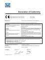
Declaration of Conformity
Watson SHDSL Router, 2 pair, 8x Ethernet
Watson SHDSL Router, 4 pair, 8x Ethernet
SZ.441.V400
SZ.441.V800
Schmid Telecom AG, Binzstrasse 35, CH-8045 Zurich
Manufacturer:
The products mentioned above comply with the regulations of the following European Directives:
The compliance of the above mentioned product with the re89/336/EEC
quirements of the directive 89/336/EEC and 2004/108/EC is
2004/108/EC
ensured by complete application of the following harmonized
Directive containing requirements regarding
European Standards:
electromagnetic compatibility.
EN 300386 v1.3.1
The compliance of the above mentioned product with the re73/23/EEC
quirements
of the directive 73/23/EEC and 2006/95/EC is en2006/95/EC
sured by complete application of the following harmonized
Directive containing requirements regarding
European Standards:
safety.
EN 60950-1:2006 (IEC 60950-1:2005)
The compliance of the above mentioned product with the re99/5/EEC
quirements of the directive 99/5/EEC is ensured by complete
Directive containing requirements regarding
application of the following harmonized European Standards:
Radio & Telecommunication Terminal
EN 300386 v1.3.1
Equipment.
EN 60950-1:2006 (IEC 60950-1:2005)
The compliance of the above mentioned products with the specified requirements of the applicable directives
and harmonized and non-harmonized standards is shown in the following internal and external test reports:==
WNGN_SHDSL_CPE_4_pair_EMC_Report_preseries.doc
EMCKP803A Schmid Telecom.pdf
WNGN_SHDSL_CPE_4_pair_EE_Report_preseries.doc
ir3570_2_LDAP_SMTP_12182006-020928.pdf
CE Label attached to the product(s):
Issued by:
Place and date:
Signatures:
Revision: 2012-02-15
moulded into backplane
Schmid Telecom AG, Binzstrasse 35, CH-8045 Zurich
Zurich, 14/05/2007
Signature 1
Signature 2
Ronny Colotto
Rolf Frey
Important Safety Precautions
To reduce the risk of fire, bodily injury, and damage to the equipment, observe
the following precautions:
Read and follow all warning notices and instructions marked on the product
or included in the manual.
This product is to be used with telecommunications circuits. Take the following precautions:
Never install telephone wiring during a lightning storm.
Never install telephone jacks in wet locations unless the jack is specifically designed for wet locations.
J Never touch un-insulated telephone wires or terminals unless the telephone line has been disconnected at the network interface.
J Use caution when installing or modifying telephone lines.
J Avoid using a telephone (other than a cordless type) during an electrical
storm. There may be a remote risk of electric shock from lightning.
J Do not use the telephone to report a gas leak in the vicinity of the leak.
Condensation may occur externally or internally if this product is moved from
a colder room to a warmer room. When moving this product under such conditions, allow ample time for this product to reach room temperature and to
dry before operating.
J
J
This product is intended for use in environments as stated in the technical
specifications. Do not use this product in areas classified as hazardous locations. Such areas include patient care areas of medical and dental facilities,
oxygen-laden environments, or industrial facilities. Contact your local electrical authority governing building construction, maintenance, or safety for more
information regarding the installation of this product.
Slots and openings in this product are provided for ventilation and should
never be blocked or covered, since these ensure reliable operation of this
product and protect it from overheating. This product should not be placed in
a built-in apparatus such as a rack unless the apparatus has been specifically
designed to accommodate the product, proper ventilation is provided for the
product, and the product instructions have been followed.
This product should be placed away from radiators, heat registers, stoves, or
other pieces of equipment that produce heat. Allow sufficient air circulation
around the product during use to ensure adequate cooling of the device.
Do not use this product in a wet location.
This product should be operated only from the type of power source indicated
on the product's electrical ratings label. Contact your local Schmid Distributor
or local power company if you have questions about the type of power source
to use
Revision: 2012-02-15
Watson SHDSL Router
Operating Manual
Watson-SHDSL-Router-Manual.doc
Version 1.1-07
Operate this product only from power outlets protected by a fuse rated 10
Amps or less
Be sure that the power outlet you plug the power cord into is easily accessible and located as close to the equipment as possible. When you need to
disconnect power to this product, be sure to unplug the power cord from the
electrical outlet.
Do not allow anything to rest on any of the attached cables and do not position this product where persons will walk or trip on the cables.
Unplug this product from the wall outlet before cleaning. Do not use liquid
cleaners or aerosol cleaners. Use a damp cloth for cleaning.
Never push a foreign object through an opening in this product.
Unplug the product from the electrical outlet and contact your local Schmid
Distributor under the following conditions:
The power cord, extension cord, or plug is damaged.
Liquid has been spilled or an object has fallen into this product.
This product has been exposed to water.
This product has been dropped or damaged in any way.
There are noticeable signs of overheating.
This product does not operate normally when you follow the operating instructions.
Do not attempt to service this product yourself, as opening or removing covers may expose you to dangerous high voltage points or other risks. Refer
all servicing to your local Schmid Distributor.
J
J
J
J
J
J
Upon completion of any service or repairs to this product, have your local
Schmid Distributor perform any safety checks required by the repair procedure or by local codes to determine that the product is in proper operating
condition.
vi
Revision: 2012-02-15
Watson-SHDSL-Router-Manual.doc
Version 1.1-07
Watson SHDSL Router
Operating Manual
Installation Precautions
For safety reasons observe the following installation configurations:
•
Shelf or desktop
Watson SHDSL router can be installed on a shelf or desktop, as a
standalone unit. The unit should only be put into position on its rubber
feet. If the installation includes more than one unit, they should not be
stacked on top of one another to prevent overheating.
•
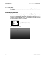
Wall mount
Wall mounting using the original wall mounting kit (not included in the
package) should only be done the following way: Orient the unit so that
the top is facing you, the front panel is at the top and the back panel with
the connectors is at the bottom. Cables should only be connected to the
unit when the wall mounting installation is completed.
This product is designed for operation in the electromagnetic environment typically found in commercial, domestic and telecommunication installations:
The electromagnetic compatibility (EMC) requirements for this product have
been selected to ensure an adequate level of immunity to electromagnetic interference in the typical operating environment. The levels do not, however
cover extreme cases which may occur in any location but with a low probability of occurrence. In special cases, situations may arise where the levels of
interference may exceed the immunity levels. In these situations, special mitigation measures may have to be employed.
Revision: 2012-02-15
vii
Limited Product Warranty
Schmid Telecom warrants that for two (2) years from the date of shipment to the
Customer, all products manufactured by Schmid Telecom will be free from defects in materials and workmanship. Schmid Telecom also warrants that products
will conform to the applicable specification and drawings for such products, as
contained in the Product Manual or in Schmid Telecom internal specifications
and drawings for such products (which may or may not be reflected in the Product Manual). This warranty only applies if Customer gives Schmid Telecom written notice of defects during the warranty period. Upon such notice, Schmid Telecom will, at its option, either repair or replace the defective item.
If Schmid Telecom is unable, in a reasonable time, to repair or replace any
equipment to a condition as warranted, Customers is entitled to a full refund of
the purchase price upon return of the equipment to Schmid Telecom. This warranty applies only to the original purchaser and is not transferable without
Schmid Telecom express written permission. This warranty becomes null and
void if Customer modifies or alters the equipment in any way, other than as specifically authorized by Schmid Telecom.
Except for the limited warranty described above, the foregoing constitutes the
sole and exclusive remedy of the Customer and the exclusive liability of Schmid
Telecom and is in Lieu of any and all other warranties (expressed or implied).
Schmid Telecom specifically disclaims all other warranties, including (without limitation), all warranties of merchantability and fitness for a particular purpose.
Some states do not allow the exclusion of implied warranties, so this exclusion
may not apply to Customer.
In no event will Schmid Telecom or its suppliers be liable to Customer for any incidental, special, punitive, exemplary or consequential damages experienced by
either Customer or a third party (including, but not limited to, loss of data or information, loss of profits, or loss of use). Schmid Telecom is not liable for damages for any cause whatsoever (whether based in contract, tort, or otherwise) in
excess of the amount paid for the item. Some states do not allow the limitation or
exclusion of liability for incidental or consequential damages, so the above limitation or exclusion may not apply to Customer.
Revision: 2012-02-15
ix
Table of Contents
Declaration of Conformity ......................................................................................................................... iii
Important Safety Precautions ..................................................................................................................... v
Installation Precautions ............................................................................................................................ vii
Limited Product Warranty .......................................................................................................................... ix
Table of Contents ....................................................................................................................................... xi
1
Related Documents ......................................................................................................................... 1-1
2
Overview ........................................................................................................................................... 2-1
2.1 Introduction .............................................................................................................................. 2-1
2.2 Applications ............................................................................................................................. 2-1
2.3 Router Types ........................................................................................................................... 2-2
2.4 Architecture.............................................................................................................................. 2-3
2.4.1 Block Diagram ............................................................................................................... 2-3
2.4.2 Ethernet Switch ............................................................................................................. 2-3
2.4.3 IP Router ....................................................................................................................... 2-3
2.4.4 SHDSL Modem ............................................................................................................. 2-4
3
Features ............................................................................................................................................ 3-1
3.1 Network connections ............................................................................................................... 3-1
3.1.1 Bridging ......................................................................................................................... 3-1
3.1.2 Routing .......................................................................................................................... 3-1
3.1.3 Dynamic Host Configuration Protocol (DHCP) .............................................................. 3-2
3.1.4 Point-to-Point Protocol over Ethernet (PPPoE) ............................................................. 3-2
3.1.5 IPSEC VPN ................................................................................................................... 3-3
3.1.6 Point-to-Point Tunneling Protocol (PPTP) ..................................................................... 3-3
3.2 Security .................................................................................................................................... 3-4
3.2.1 Access Control .............................................................................................................. 3-4
3.2.2 Port Forwarding ............................................................................................................. 3-4
3.2.3 DMZ Host ...................................................................................................................... 3-5
3.2.4 Port Triggering ............................................................................................................... 3-5
3.2.5 Website Restrictions ..................................................................................................... 3-6
3.2.6 Network Address Translation (NAT) ............................................................................. 3-6
3.2.7 Advanced Filtering ......................................................................................................... 3-6
3.2.8 Security Log ................................................................................................................... 3-7
3.3 VLAN ....................................................................................................................................... 3-7
3.3.1 Switch VLAN modes ...................................................................................................... 3-7
3.3.2 VLAN interfaces ............................................................................................................ 3-7
3.3.3 VLAN Stacking .............................................................................................................. 3-7
3.3.4 VLAN Examples ............................................................................................................ 3-8
3.4 Quality of Service (QoS) .......................................................................................................... 3-8
3.4.1 Traffic Priority ................................................................................................................ 3-9
3.4.2 Traffic Shaping .............................................................................................................. 3-9
Revision: 2012-02-15
xi
Watson SHDSL Router
Operating Manual
Watson-SHDSL-Router-Manual.doc
Version 1.1-07
3.4.3 Differentiated Services Code Point (DSCP) .................................................................. 3-9
3.4.4 IEEE 802.1p priority..................................................................................................... 3-10
3.4.5 DSCP Remark According to 802.1p CoS .................................................................... 3-10
3.4.6 Class Statistics ............................................................................................................ 3-10
3.5 DSL ........................................................................................................................................ 3-11
3.5.1 Linerates and DSL sync rates ..................................................................................... 3-11
3.5.2 Multi-pair operation ...................................................................................................... 3-11
3.5.3 Ethernet over SHDSL .................................................................................................. 3-12
3.5.4 Power Backoff ............................................................................................................. 3-14
3.5.5 DSL Performance ........................................................................................................ 3-14
3.5.6 Master / Slave.............................................................................................................. 3-15
3.5.7 DSL Clocking ............................................................................................................... 3-15
3.6 Firmware update .................................................................................................................... 3-15
3.7 Management .......................................................................................................................... 3-15
3.7.1 Management interfaces ............................................................................................... 3-15
3.7.2 Accessing the Web-based Management .................................................................... 3-16
3.7.3 Management VLAN configuration ............................................................................... 3-16
3.8 DSL Performance Monitoring ................................................................................................ 3-17
3.9 Password protection .............................................................................................................. 3-17
3.10 Restoring the default configuration ........................................................................................ 3-17
4
LEDs and Alarms ............................................................................................................................. 4-1
4.1 LEDs ........................................................................................................................................ 4-1
4.1.1 Front Panel LEDs .......................................................................................................... 4-1
4.1.2 Back Panel LEDs .......................................................................................................... 4-1
4.2 Alarm Conditions ..................................................................................................................... 4-2
5
Front and Rear Panels ..................................................................................................................... 5-1
5.1 Front Panel .............................................................................................................................. 5-1
5.2 Rear Panel ............................................................................................................................... 5-1
6
Connectors and Cables ................................................................................................................... 6-1
6.1 DSL Interface ........................................................................................................................... 6-1
6.1.1 Connector ...................................................................................................................... 6-1
6.1.2 DSL Cable ..................................................................................................................... 6-2
6.2 Ethernet Interfaces .................................................................................................................. 6-2
6.3 Power and Grounding .............................................................................................................. 6-3
6.3.1 Power Connector ........................................................................................................... 6-3
6.3.2 Ground Connector ......................................................................................................... 6-3
7
Technical Specifications ................................................................................................................. 7-1
7.1 Interfaces ................................................................................................................................. 7-1
7.1.1 DSL Line Interface ......................................................................................................... 7-1
7.1.2 Ethernet Interfaces ........................................................................................................ 7-1
7.2 Power Consumption ................................................................................................................ 7-1
7.3 Ethernet ................................................................................................................................... 7-1
7.4 Management Functions ........................................................................................................... 7-2
7.5 Environment............................................................................................................................. 7-2
7.5.1 Climatic Conditions ........................................................................................................ 7-2
7.5.2 Safety ............................................................................................................................ 7-2
7.5.3 EMC............................................................................................................................... 7-2
7.6 Physical dimensions and weight .............................................................................................. 7-2
8
Terminology ..................................................................................................................................... 8-1
xii
Revision: 2012-02-15
Watson-SHDSL-Router-Manual.doc
Version 1.1-07
Watson SHDSL Router
Operating Manual
Figures
Figure 2-1: Point-to-Multipoint Ethernet Services .............................................................................. 2-1
Figure 2-2: Point-to-point Ethernet Services ...................................................................................... 2-2
Figure 2-3: Watson SHDSL router block diagram ............................................................................. 2-3
Figure 3-1: VLAN configuration for traffic concentration .................................................................... 3-8
Figure 3-1: G.SHDSL.bis linerates ................................................................................................... 3-11
Figure 3-3: Ethernet over DSL with HDLC encapsulation ................................................................ 3-13
Figure 3-4: EFM fragmentation and framing .................................................................................... 3-13
Figure 5-1: Front panel ...................................................................................................................... 5-1
Figure 5-2: Rear panel ....................................................................................................................... 5-1
Figure 6-1: DSL Connector ................................................................................................................ 6-1
Figure 6-2: Ethernet Connector ......................................................................................................... 6-2
Figure 6-3: Power Connector ............................................................................................................. 6-3
Figure 6-4: Ground Connector ........................................................................................................... 6-3
Tables
Table 2-1: Watson SHDSL Router types ........................................................................................... 2-2
Table 3-1: Naming of DSL ports and wire pairs ............................................................................... 3-12
Table 3-2: Power Backoff................................................................................................................. 3-14
Table 4-1: Tabletop front LED indications.......................................................................................... 4-1
Table 4-2: Ethernet LED Indicators .................................................................................................... 4-2
Table 6-1: DSL connector pin assignment ......................................................................................... 6-1
Table 6-2: Ethernet Connector........................................................................................................... 6-2
Revision: 2012-02-15
=
xiii
1
Related Documents
[1] Schmid Telecom, Watson SHDSL Router GUI Manual
[2] Schmid Telecom, Watson SHDSL Router Application Manual
[3] Schmid Telecom, Watson SHDSL CLI Manual
[4] ETSI TS 101 524, 2004
[5] EN 30059
Revision: 2012-02-15
1-1
2
Overview
2.1 Introduction
Watson SHDSL router is an innovative Next-Generation DSL solution designed
for enabling high-speed Internet or point-to-point connectivity to business customers.
Watson SHDSL router uses Ethernet in the First Mile (EFM) technology, which is
a transparent extension of Ethernet-base LANs into wide area networks. No conversion of packet formats is required when transiting between LAN and WAN.
This transparency greatly simplifies network operations, reduces deployment
costs, and increase service levels. EFM includes maintenance functions that
make the operation of large wide-area Ethernets feasible.
Watson SHDSL router features either two or four SHDSL ports. Symmetrical data rates up to 15.3 Mbit/s are available on each copper pair. Using EFM pair
bonding, data rates of 49 Mbit/s over 4 copper pairs can be achieved.
Watson SHDSL router integrates an eight port Ethernet switch, an SPI Firewall
and a VPN gateway, which protects networks by providing robust security features and standard IPSec Virtual Private Network tunneling.
Watson SHDSL router features a user-friendly graphical Web-based management interface. This highly intuitive GUI is easily mastered by the novice user,
but is also highly flexible and offers sophisticated users and system administrators full control of the system. A description of the GUI can be found in the “Watson SHDSL Router GUI Manual” [1]
2.2 Applications
Figure 2-1 shows deployment of Watson SHDSL router to deliver Point – to –
Multipoint Ethernet Services:
peapiI=NJQ=é~áêë
t~íëçå=peapi=êçìíÉê
EpwKQQNKsQMMI=
pwKQQNKsUMMF
kdk
Ä~ÅâÄçåÉ
t~íëçå=bíÜÉêåÉí=
éäìÖJáå=
EpwKUSSKsSRQF
Figure 2-1: Point-to-Multipoint Ethernet Services
Revision: 2012-02-15
2-1
Watson SHDSL Router
Operating Manual
Watson-SHDSL-Router-Manual.doc
Version 1.1-07
Several Watson Ethernet plug-in cards (SZ.866.V654) are installed in a subrack
at the central office or the point of presence. Depending on the service offered
each plug-in can serve between one and four customers. At the customer premises a Watson SHDSL router is installed. Traffic from each customer is available
at a dedicated Ethernet interface in the central office. Alternatively traffic from
several customers can be aggregated to a single Ethernet port. Advanced VLAN
functions allow for customer isolation and traffic management. Depending on the
distance and the number of wire pairs linerate up to 49 Mbps are available.
Watson SHDSL router can also be deployed point-to-point as shown in Figure
2-2:
peapiI=NJQ=é~áêë
t~íëçå=peapi=êçìíÉê
EpwKQQNKsQMMI=
pwKQQNKsUMMF
t~íëçå=peapi=êçìíÉê
EpwKQQNKsQMMI=
pwKQQNKsUMMF
Figure 2-2: Point-to-point Ethernet Services
For these applications two Watson SHDSL routers are connected back to back
with one of the modems being configured as DSL master and the other one as
DSL slave. Depending on the distance and the number of wire pairs available
linerate up to 49 Mbps are available. VLAN and MAC Address filtering functions
allow for traffic management and optimal use of the available DSL bandwidth.
Refer to the “Watson SHDSL Router Application Manual” [3] which described
several applications that can be realized with the Watson SHDSL router.
2.3 Router Types
The following Watson SHDSL routers are available:
Description
Order Code
Watson SHDSL Router, 2 pair, 8x Ethernet
Watson SHDSL Router, 4 pair, 8x Ethernet
SZ.441.V400
SZ.441.V800
Table 2-1: Watson SHDSL Router types
2-2
Revision: 2012-02-15
Watson-SHDSL-Router-Manual.doc
Version 1.1-07
Watson SHDSL Router
Operating Manual
2.4 Architecture
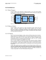
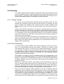
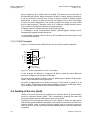
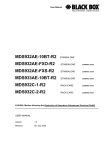
2.4.1 Block Diagram
ETH1
Port1
ETH2
Port2
ETH3
Port3
ETH4
Port4
ETH5
Port5
ETH6
Port6
ETH7
Port7
ETH8
Port8
Ethernet
Switch
Trunk
LAN
Packet
Processor
WAN
SHDSL
modem
Port1
DSL1
Port2
DSL2
Port3
DSL3
Port4
DSL4
DSL Wire pairs
Ethernet User Interfaces
Watson SHDSL router integrates an Ethernet Switch, an IP router and a SHDSL
modem which transport and process Ethernet/IP packets between the Ethernet
user interfaces and the DSL wire pairs:
Figure 2-3: Watson SHDSL router block diagram
2.4.2 Ethernet Switch
Watson SHDSL router features an eight port Ethernet switch. Eight LAN ports
(ETH1 .. ETH8) are available at the back of Watson SHDSL router. The switch
trunk port (Trunk) is connected internally to the packet processor LAN port
(LAN). The Ethernet switch features a 2 Gbps non-blocking core which guarantees wire-speed performances.
2.4.3 IP Router
The IP router features bridging, routing, security, VPN and many other functions.
Bridging bases the forwarding decision on the MAC (Media Access Control) address, while routing does it on the network layer (IP) address. Bridging allows
transporting packets of network layer protocols that it does not route. In bridge
mode all non-local packets are bridged to the WAN.
The IP router includes comprehensive and robust security services: Statefull
Packet Inspection Firewall, user authentication protocols and password protection mechanisms. These features together allow users to connect their computers to the Internet and simultaneously to be protected from the security threats of
the Internet.
IPSEC VPN capability allows to establish a Virtual Private Network (VPN) to connect with business partners and branch offices using data encryption through the
Internet. It provides secure communications without the expense of leased lines.
Watson SHDSL router VPN implementation is based on the IPSec standard and
is fully interoperable with other IPSec-based VPN products.
Revision: 2012-02-15
=
2-3
Watson SHDSL Router
Operating Manual
Watson-SHDSL-Router-Manual.doc
Version 1.1-07
2.4.4 SHDSL Modem
The SHDSL modem is responsible for transporting the Ethernet packets over the
DSL wire pairs. The Packet Transport Mode (PTM TPS-TC layer) of the SHDSL
ETSI TS 101 524 / ITU-T G.991.2 standards is used for this purpose. The modem supports the following two standardized packet mode encapsulation: HDLC
and IEEE EFM 64b/65b framing.
2-4
Revision: 2012-02-15
3
Features
3.1 Network connections
Watson SHDSL router supports various network connections. Besides the physical LAN and WAN connections, other logical connections, using tunneling protocols over existing connections, such as PPP and VPN can be configured.
Every network connection in Watson SHDSL router can be configured as one of
three types: WAN, LAN or DMZ. This provides high flexibility and increased functionality.
For example a network connection can be defined as a DMZ (Demilitarized) network. Although the network is physically inside Watson SHDSL router, it will
function as an unsecured, independent network, for which Watson merely acts
as a router.
3.1.1 Bridging
With the network bridging feature several network connections can be combined
together under one virtual network.
For example, creating one network for LAN Ethernet and WAN Ethernet devices.
3.1.2 Routing
Watson SHDSL router can be setup to use static or dynamic routing. Dynamic
routing automatically adjusts how packets travel on the network, whereas static
routing specifies a fixed routing path to neighboring destinations.
Watson SHDSL router supports two different routing modes:
In ROUTE mode Watson functions as a router between two networks.
In NAPT mode Watson performs Network Address and Port Translation. NAPT
refers to network address translation involving the mapping of port numbers, allowing multiple machines to share a single IP address. NAPT should be used if
the LAN encompasses multiple devices, a topology that necessitates port translation in addition to address translation.
Revision: 2012-02-15
3-1
Watson SHDSL Router
Operating Manual
Watson-SHDSL-Router-Manual.doc
Version 1.1-07
3.1.3 Dynamic Host Configuration Protocol (DHCP)
Watson SHDSL router’s WAN connection can be configured to act as a DHCP
client. The server that assigns the router with an IP address also assigns a subnet mask that can be overridden if necessary.
Watson SHDSL router’s Dynamic Host Configuration Protocol (DHCP) server
makes it possible to easily add computers that are configured as DHCP clients to
the local network. It provides a mechanism for allocating IP addresses and delivering network configuration parameters to such hosts. Watson SHDSL router’s
default DHCP server is the LAN bridge.
A client (host) sends out a broadcast message on the LAN requesting an IP address for itself. The DHCP server then checks its list of available addresses and
leases a local IP address to the host for a specific period of time and simultaneously designates this IP address as `taken'. At this point the host is configured
with an IP address for the duration of the lease.
The host can choose to renew an expiring lease or let it expire. If it chooses to
renew a lease then it will also receive current information about network services,
as it did with the original lease, allowing it to update its network configurations to
reflect any changes that may have occurred since it first connected to the network. If the host wishes to terminate a lease before its expiration it can send a
release message to the DHCP server, which will then make the IP address available for use by others.
Watson SHDSL router's DHCP server:
Displays a list of all DHCP host devices connected to it
Defines the range of IP addresses that can be allocated in the LAN
Defines the length of time for which dynamic IP addresses are allocated
Provides the above configurations for each logical LAN connection which can
be configured and enabled/disabled separately
Can assign a static lease to a LAN PC so that it receives the same IP address each time it connects to the network, even if this IP address is within
the range of addresses that the DHCP server may assign to other computers.
Provides the DNS server with the host name and IP address of each PC that
is connected to the LAN
Additionally, Watson SHDSL router can act as a DHCP relay, escalating DHCP
responsibilities to a WAN DHCP server.
In this case, Watson SHDSL router will act merely as a router, while its LAN
hosts will receive their IP addresses from a DHCP server on the WAN.
3.1.4 Point-to-Point Protocol over Ethernet (PPPoE)
Watson SHDSL router supports the Point-to-Point Protocol over Ethernet
(PPPoE).
PPPoE enables your local network PCs that communicate on an Ethernet network to exchange information with PCs on the Internet. PPPoE supports the protocol layers and authentication widely used in PPP and enables a point-to-point
connection to be established in the normally multipoint architecture of Ethernet. A
discovery process in PPPoE determines the Ethernet MAC address of the remote device in order to establish a session.
3-2
Revision: 2012-02-15
Watson-SHDSL-Router-Manual.doc
Version 1.1-07
Watson SHDSL Router
Operating Manual
Watson SHDSL router’s Point-to-Point Protocol (PPP) currently supports four authentication protocols: Password Authentication Protocol (PAP), Challenge
Handshake Authentication Protocol (CHAP), and Microsoft CHAP version 1 and
2.
PPP supports encryption facilities to secure the data across the network connection. A wide variety of encryption methods may be negotiated, although typically
only one method is used in each direction of the link. Please note that PPP encryption can only be used with MS-CHAP or MS-CHAP-V2 authentication protocols.
Also supported is the PPP Compression Control Protocol (CCP) which is responsible for configuring, enabling, and disabling data compression algorithms on
both ends of the point-to-point link. It is used to signal a failure of the compression/ decompression mechanism in a reliable manner.
3.1.5 IPSEC VPN
Watson SHDSL router integrates IPSEC VPN capabilities. It allows establishing
a Virtual Private Network (VPN) to connect with business partners and branch offices using data encryption through the Internet. It provides secure communications without the expense of leased lines. Watson SHDSL router VPN implementation is based on the IPSec standard and is fully interoperable with other IPSecbased VPN products.
VPN, IPSec and PPTP features enable Watson SHDSL router to act as a VPN
client, allowing a user to securely connect with remote computers without needing to run any additional PC-based VPN software; or as a VPN server, allowing a
user to connect to a home or office network from a remote location.
In addition, Watson's VPN pass-through support enables a user to establish a
VPN connection from a PC-based VPN client by allowing the connection to pass
transparently through the router's firewall and Network Address Translation
(NAT).
3.1.6 Point-to-Point Tunneling Protocol (PPTP)
Point-to-Point Tunneling Protocol (PPTP) is a protocol developed by Microsoft
targeted at creating VPN connections over the Internet. This enables remote users to access the router via any ISP that supports PPTP on its servers. PPTP
encapsulates network traffic, encrypts content using Microsoft's Point-to-Point
Encryption (MPPE) protocol that is based on RC4, and routes using the generic
routing encapsulation (GRE) protocol.
With Watson SHDSL router, PPTP is targeted at serving two purposes:
Connection to the Internet using user name and password authentication.
Connection to a remote network using a Virtual Private Network (VPN) tunnel
over the Internet. This enables secure transfer of data to another location
over the Internet, using user name and password authentication.
Watson SHDSL router can also act as a Point-to-Point Tunneling Protocol Server
(PPTP Server), accepting PPTP client connection requests.
Revision: 2012-02-15
=
3-3
Watson SHDSL Router
Operating Manual
Watson-SHDSL-Router-Manual.doc
Version 1.1-07
3.2 Security
The firewall supports advanced filtering, designed to allow comprehensive control
over the firewall's behavior. Additional features, including surfing restrictions and
access control, can also be easily configured locally by the user through a userfriendly Web-based interface, or remotely by a service provider.
3.2.1 Access Control
The access control features allow blocking specific computers within the local
network from accessing certain services on the Internet. For example, you may
want to prohibit one computer from surfing the Web, another computer from
transferring files using FTP, and the whole network from receiving incoming email.
Access control defines restrictions on the types of requests that may pass from
the local network out to the Internet, and thus may block traffic flowing in both directions. It can also be used for allowing specific services when maximum security is configured. In the e-mail example given above, you may prevent computers
in the local network from receiving e-mail by blocking their outgoing requests to
POP3 servers on the Internet.
There are numerous services that should be considered blocking, such as online
games and file sharing servers. For example, the firewall can be configured to
block certain P2P and file sharing applications not to put business at risk from illegally traded copyright files.
3.2.2 Port Forwarding
In its default state, Watson SHDSL router blocks all external users from connecting to or communicating with the local network. Therefore the system is safe
from hackers who may try to intrude on the network and damage it. However,
you may want to expose your local network to the Internet in certain limited and
controlled ways in order to enable some applications to work from the LAN and
to enable Internet-access to servers in the LAN. The Port Forwarding feature
supports both of these functionalities.
For example, if you want to use a File Transfer Protocol (FTP) application on one
of your PCs, you would simply select 'FTP' from the list and enter the local IP
address or host name of the designated computer. All FTP-related data arriving
at Watson SHDSL router from the Internet will henceforth be forwarded to the
specified computer.
Similarly, you can grant Internet users access to servers inside your local network, by identifying each service and the PC that will provide it. This is useful, for
example, if you want to host a Web server inside your local network. When an Internet user points his/her browser to Watson SHDSL router external IP address,
the router will forward the incoming HTTP request to your Web server.
With one external IP address (Watson SHDSL router main IP address), different
applications can be assigned to the LAN computers, however each type of application is limited to use one computer. For example, you can define that FTP will
use address X to reach computer A and Telnet will also use address X to reach
computer A, but attempting to define FTP to use address X to reach both computer A and B will fail. Watson SHDSL router therefore provides the ability to add
3-4
Revision: 2012-02-15
Watson-SHDSL-Router-Manual.doc
Version 1.1-07
Watson SHDSL Router
Operating Manual
additional public IP addresses to port forwarding rules, and enter into the 'NAT IP
Addresses Pool'. You will then be able to define FTP to use address X to reach
computer A and address Y to reach computer B.
Additionally, port forwarding enables you to redirect traffic to a different port instead of the one to which it was designated. Lets say, that you have a Web server running on your PC on port 8080 and you want to grant access to this server
to anyone who accesses Watson SHDSL router via HTTP. To accomplish this,
do the following:
Define a port forwarding rule for the HTTP service, with the PC's IP or host
name.
Specify 8080 in the 'Forward to Port' field.
All incoming HTTP traffic will now be forwarded to the PC running the Web
server on port 8080.
When setting a port forwarding service, you must ensure that the port is not already in use by another application, which may stop functioning.
Note: Some applications, such as FTP, TFTP, PPTP and H323, require the support of special specific Application Level Gateway (ALG) modules in order to
work inside the local network. Data packets associated with these applications
contain information that allows them to be routed correctly. An ALG is needed to
handle these packets and ensure that they reach their intended destinations.
Watson SHDSL router is equipped with a robust list of ALG modules in order to
enable maximum functionality in the local network.
The ALG is automatically assigned based on the destination port.
3.2.3 DMZ Host
The DMZ (Demilitarized) Host feature allows one local computer to be exposed
to the Internet. Designate a DMZ host when:
You wish to use a special-purpose Internet service, such as an on-line application or video-conferencing program, that is not present in the Port Forwarding list
and for which no port range information is available.
You are not concerned with security and wish to expose one computer to all services without restriction.
Warning: A DMZ host is not protected by the firewall and may be vulnerable to
attack. Designating a DMZ host may also put other computers in the local network at risk. When designating a DMZ host, you must consider the security implications and protect it if necessary.
An incoming request for access to a service in the local network, such as a Webserver, is fielded by Watson SHDSL router. It will forward this request to the DMZ
host (if one is designated) unless the service is being provided by another PC in
the home network (assigned in Port Forwarding), in which case that PC will receive the request instead.
3.2.4 Port Triggering
Port triggering can be used for dynamic port forwarding configuration. By setting
port triggering rules, you can allow inbound traffic to arrive at a specific LAN
host, using ports different than those used for the outbound traffic. This is called
Revision: 2012-02-15
=
3-5
Watson SHDSL Router
Operating Manual
Watson-SHDSL-Router-Manual.doc
Version 1.1-07
port triggering since the outbound traffic triggers to which ports inbound traffic is
directed.
For example, consider a server that is accessed using UDP protocol on port
2222. The server responds by connecting the user using UDP on port 3333 when
starting sessions. In such a case you must use port triggering, since this scenario conflicts with the following default firewall settings:
The firewall blocks inbound traffic by default.
The server replies to Watson SHDSL router IP, and the connection is not
sent back to your host, since it is not part of a session.
In order to solve this you need to define a Port Triggering entry, which allows inbound traffic on UDP port 3333, only after a LAN host generated traffic to UDP
port 2222. This will result in accepting the inbound traffic from the server, and
sending it back to the LAN Host which originated the outgoing traffic to UDP port
2222.
3.2.5 Website Restrictions
Watson SHDSL router can be configured to block specific Internet websites so
that they cannot be accessed from computers in the local network. Moreover, restrictions can be applied to a comprehensive and automatically-updated table of
sites to which access is not recommended.
3.2.6 Network Address Translation (NAT)
Watson SHDSL router features a configurable Network Address Translation
(NAT) and Network Address Port Translation (NAPT) mechanism, allowing to
control the network addresses and ports of packets routed through the router.
When enabling multiple computers on the local network to access the Internet
using a fixed number of public IP addresses, you can statically define which LAN
IP address will be translated to which NAT IP address and/or ports.
By default, Watson SHDSL router operates in NAPT routing mode. However, you
can control your network translation by defining static NAT/NAPT rules. Such
rules map LAN computers to NAT IP addresses.
The NAT/NAPT mechanism is useful for managing Internet usage in your LAN,
or complying with various application demands. For example, you can assign
your primary LAN computer with a single NAT IP address, in order to assure its
permanent connection to the Internet. Another example is when an application
server with which you wish to connect, such as a security server, requires that
packets have a specific IP address - you can define a NAT rule for that address.
3.2.7 Advanced Filtering
Advanced filtering is designed to allow comprehensive control over the firewall's
behavior. You can define specific input and output rules, control the order of logically similar sets of rules and make a distinction between rules that apply to WAN
and LAN interfaces
3-6
Revision: 2012-02-15
Watson-SHDSL-Router-Manual.doc
Version 1.1-07
Watson SHDSL Router
Operating Manual
3.2.8 Security Log
The Security Log displays a list of firewall-related events, including attempts to
establish inbound and outbound connections, attempts to authenticate through
an administrative interface (Web-based management or Telnet terminal), firewall
configuration and system start-up..
3.3 VLAN
Watson SHDSL router supports VLAN functions according to IEEE 802.1q.
3.3.1 Switch VLAN modes
The switch supports two VLAN modes: 802.1q and transparent.
In 802.1q mode each of the eight Ethernet switch ports (Port1 .. Port8) and the
switch trunk port (Trunk), can be member of one or several VLANs. Each port
can be member of maximum 15 VLANs. Each VLAN has a VLAN Identifier (VID)
between 1 and 4094.
Upon reception of an Ethernet packet at a port its VID is checked against the
VIDs of all VLANs this port is a member of. Packets that do not carry one of these VIDs will be discarded.
For untagged packets the default VID for the port is used to determine VLAN
membership.
Packets are only forwarded to ports that are a member of the VLAN of this packet.
Upon transmission the packet will be tagged with the VLAN tag originally received. If the packet was untagged then the default tag of the receiving port is
added to the packet. The port can also be configured to send the packets untagged.
In VLAN transparent mode all Ethernet switch ports are member of all VLANs
and untagged packets will not be tagged with a default VID. The packet forwarding is only based on MAC addresses.
3.3.2 VLAN interfaces
Watson SHDSL router allows you to create Virtual LAN (VLAN) interfaces on the
router in order to connect to external virtual networks.
It is also possible to create a dedicated VLAN management interface that can be
used for managing the Watson SHDSL router.
3.3.3 VLAN Stacking
A service provider can use VLAN stacking to allow it to distinguish multiple customers VLANs, even those with the same (customer-assigned) VLAN ID, within
its network.
Use VLAN stacking to add an outer VLAN tag to the inner IEEE 802.1Q tagged
frames that enter the network. By tagging the tagged frames ("double-tagged"
frames), the service provider can manage up to 4,094 VLAN groups with each
Revision: 2012-02-15
=
3-7
Watson SHDSL Router
Operating Manual
Watson-SHDSL-Router-Manual.doc
Version 1.1-07
group containing up to 4,094 customer VLANs. This allows a service provider to
provide different service, based on specific VLANs, for many different customers.
A service provider's customer may require a range of VLANs to handle multiple
applications. A service provider's customer can assign his own inner VLAN tags
on ports for these applications. The service provider can assign an outer VLAN
tag for each customer. Therefore, there is no VLAN tag overlap among customers, so traffic from different customers is kept separate.
In Bridge mode the Watson has two VLAN stacking mode:
In ‘Transparent’ mode VLAN stacked frames (“double-tagged” frames) will be
transparently bridged through the device
In ‘Rule Based’ mode an outer VLAN tag will be added to the frames when a set
of rules will be matched.
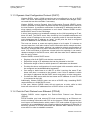
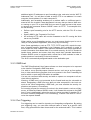
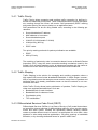
3.3.4 VLAN Examples
Figure 3-1 shows how the VLAN function can be used for traffic separation:
Ethernet Switch
ETH1
ETH3
1
1
ETH4
ETH5
2
2
ETH6
ETH7
3
3
VLA
N1
VLAN 2
VL A
1, 2, 3
WAN
Tagged
Untagged
ETH2
N3
ETH8
1
Default VLAN Tag
1
VLAN Port Membership
Figure 3-1: VLAN configuration for traffic concentration
In this example the Switch is configured as 802.1q mode and three Ethernet
ports are configured with different VLAN tags.
Upon ingress into Watson SHDSL router the packets get a default VLAN tag between 1 and 3 based on their ingress port.
All traffic is aggregated to the Switch trunk port (Trunk) which is member of all
three VLANs. The packets egress Watson SHDSL router with VLAN tags, allowing to separate traffic streams from the three Ethernet ports.
3.4 Quality of Service (QoS)
Quality of Service refers to the capability of a network device to provide better
service to selected network traffic. This is achieved by shaping the traffic and
processing higher priority traffic before lower priority traffic.
Typically the most significant bottleneck of the network is where the high speed
LAN meets limited broadband bandwidth. Special QoS mechanisms are built into
Watson SHDSL router to ensure that this sudden drop in connectivity speed is
taken into account when prioritizing and transmitting real-time service-related data packets.
3-8
Revision: 2012-02-15
Watson-SHDSL-Router-Manual.doc
Version 1.1-07
Watson SHDSL Router
Operating Manual
3.4.1 Traffic Priority
Traffic Priority allows managing and avoiding traffic congestion by defining inbound and outbound priority rules. These rules determine the priority that packets, traveling through the router, will receive. QoS parameters (DSCP marking
and packet priority) are set per packet, on an application basis.
QoS parameters can be set using flexible rules, according to the following parameters:
Source/destination IP address,
MAC address or host name
Source/destination ports
VLAN ID (S-VLAN and/or C-VLAN)
VLAN priority (802.1p)
DSCP value
Two priority marking methods for packet prioritization are available:
DSCP
802.1p Priority
The matching of packets by rules is connection-based, known as Stateful Packet
Inspection (SPI), using the same connection-tracking mechanism used by the
firewall. Once a packet matches a rule, all subsequent packets with the same attributes receive the same QoS parameters, both inbound and outbound.
3.4.2 Traffic Shaping
Traffic Shaping is the solution for managing and avoiding congestion where a
high speed LAN meets limited broadband bandwidth. A traffic shaper is essentially a regulated queue that accepts uneven and/or bursty flows of packets and
transmits them in a steady, predictable stream so that the network is not overwhelmed with traffic.
While Traffic Priority allows basic prioritization of packets, Traffic Shaping provides more sophisticated definitions. Such are:
Bandwidth limit for each interface
Bandwidth limit for classes of rules
Prioritization policy
TCP serialization
3.4.3 Differentiated Services Code Point (DSCP)
Differentiated Services (DiffServ) is a Class of Service (CoS) model that enhances best-effort Internet services by differentiating traffic by users, service requirements and other criteria. Packets are specifically marked, allowing network
nodes to provide different levels of service, as appropriate for voice calls, video
playback or other delay-sensitive applications, via priority queuing or bandwidth
allocation, or by choosing dedicated routes for specific traffic flows.
Revision: 2012-02-15
=
3-9
Watson SHDSL Router
Operating Manual
Watson-SHDSL-Router-Manual.doc
Version 1.1-07
DiffServ defines a field in IP packet headers referred to as DSCP. Hosts or routers passing traffic to a DiffServ-enabled network will typically mark each transmitted packet with an appropriate DSCP. The DSCP markings are used by DiffServ
network routers to appropriately classify packets and to apply particular queue
handling or scheduling behavior.
Watson SHDSL router provides a configurable table of predefined DSCP values,
which are mapped to 802.1p priority marking method.
3.4.4 IEEE 802.1p priority
The IEEE 802.1p priority marking method is a standard for prioritizing network
traffic at the data link/Mac sub-layer. 802.1p traffic is simply classified and sent to
the destination, with no bandwidth reservations established.
The 802.1p header includes a 3-bit prioritization field, which allows packets to be
grouped into eight levels of priority. Watson SHDSL router maps these eight levels to three main priorities: high, medium and low. By default, values six and
seven are mapped to high priority, which may be assigned to network-critical traffic. Values four and five are mapped to medium priority, which may be applied to
delay-sensitive applications, such as interactive video and voice. Values three to
zero are mapped to low priority, which may range from controlled-load applications down to "loss eligible" traffic. The zero value is normally used for best-effort
traffic. It is the default value for traffic with unassigned priority.
3.4.5 DSCP Remark According to 802.1p CoS
When creating a VLAN interface over a LAN connection, it is possible to determine the IP header's Differentiated Services Code Point (DSCP) priority value
according to the VLAN header's 802.1p Class of Service (CoS) tag. The DSCP
value can then be used for Quality of Service (QoS) traffic prioritization.
3.4.6 Class Statistics
Watson SHDSL router provides accurate, real-time information on the traffic
moving through the defined device classes. For example, the amount of packets
sent, dropped or delayed, are just a few of the parameters that can be monitored
per each shaping class.
3-10
Revision: 2012-02-15
Watson-SHDSL-Router-Manual.doc
Version 1.1-07
Watson SHDSL Router
Operating Manual
3.5 DSL
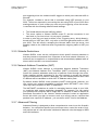
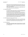
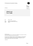
3.5.1 Linerates and DSL sync rates
Watson EFM Plug-in modems support symmetrical DSL transmission as specified in ETSI TS 101 524 (SDSL) and ITU-T G.991.2 Annex B/G (G.SHDSL.bis).
The linecode used is either TC-PAM 16 or TC-PAM 32. With TC-PAM 16 the
supported linerate rates per pair are from 192 kbit/s to 3’840 kbit/s (3 - 60
timeslots of 64 kbit/s). TC-PAM 32 uses a 32-level linecode and allows a linerate
per pair from 768 kbit/s to 10’176 kbit/s (12 - 159 timeslots).
G.SHDSL, ETSI TS 101 524
16 TC -PAM
G.SHDSL.bis, e -SDSL
16 TC -PAM
32 TC -PAM
192 768
2'304
3'840
5'696
Linerate
kBps
Figure 3-2: G.SHDSL.bis linerates
For certain linerates either TC-PAM 16 or TC-PAM 32 can be configured in the
modem. TC-PAM 16 has better DSL performance than TC-PAM 32. However
with linerates rates higher than 2’304 kbit/s (36 timeslots) and TC-PAM 16 the
symbol rate over the DSL becomes higher than what was specified in the original
version of ETSI TS 101 524. Higher symbol rates mean wider PSDs which in turn
can lead to higher interference to other DSL systems in the same cable binder,
e.g. ADSL, ADSL2, ADSL2+, VDSL2.
Beside the standards the Watson SHDSL router does as well support a 64- and
128-level linecode (TC-PAM 64 and TC-PAM 128). The number of timeslots per
pair when using TC-PAM 64 is from 160 to 199, the line rate when using TCPAM 64 is from 10’240 kbit/s to 12’736 kbit/s. The number of timeslots per pair
when using TC-PAM 128 is from 200 to 240, the line rate when using TC-PAM
128 is from 12’800 kbit/s to 15’360 kbit/s.
Please note that the linecodes PAM 64 and PAM 128 are much more sensitive
for interferences and noise and are therefore more difficult to apply in the real
network. For the same reason the line distances applicable for PAM 64 and PAM
128 are normally much shorter than with PAM 16 or PAM 32.
3.5.2 Multi-pair operation
Watson SHDSL router supports multi-pair operation. This allows aggregation of
individual DSL wire pairs for higher speeds or increased reach at a given speed.
Watson SHDSL router supports two different multi-pair aggregation methods: the
IEEE 802.3ah EFM PAF and the ETSI / ITU-T SHDSL M-pair mode.
EFM PAF allows configuring different linerate on the different DSL wire pairs with
a maximum linerate ratio of 1 to 4. It is also resilient to DSL wire pair failure. If
one pair fails the link is maintained using the other pairs. The data service is running at a lower speed, but is kept uninterrupted.
Revision: 2012-02-15
=
3-11
Watson SHDSL Router
Operating Manual
Watson-SHDSL-Router-Manual.doc
Version 1.1-07
The SHDSL M-pair mode is used for backwards compatibility reason when Watson SHDSL router is connected to Watson Ethernet plug-in (SZ.866.V654) as
showed in Figure 2-1. In this mode each wire pair of Watson SHDSL router must
be configured with the same linerate. If one pair fails then the entire link must be
restarted.
A multi-pair DSL link is called a span. Watson SHDSL router has only one span.
The span can have 1, 2, 3 or 4 DSL wire pairs.
The following naming convention is used in multi-pair operation on Watson
SHDSL router:
DSL ports within the span are named 1, 2, 3 and 4. Depending on the number of wire pairs within the span the DSL ports 2, 3 or 4 might not be used.
Physical wire pairs available at the DSL connector are named a, b, c and d
(see Table 3-1 for the DSL connector pin assignment).
Depending on the configuration of Watson SHDSL router the following combinations are possible:
default
DSL
ports
Wire pairs
1
2
3
1
1, 2
1, 2, 3
4
1, 2, 3, 4
(a1, a2)
(a1, a2), (b1, b2)
(a1, a2), (b1, b2), (c1, c2)
(a1, a2), (b1, b2), (c1, c2), (d1,
d2)
Table 3-1: Naming of DSL ports and wire pairs
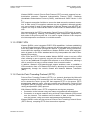
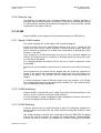
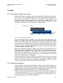
3.5.3 Ethernet over SHDSL
Watson SHDSL router uses the Packet Transport Mode (PTM TPS-TC layer) of
the ETSI TS 101 524 / ITU-T G.991.2 standards for transporting the Ethernet
packets over the DSL wire pairs. As encapsulation method HDLC and IEEE EFM
64b/65b framing are supported.
The HDLC packet encapsulation mode is used for connecting a Watson SHDSL
router to a Watson Ethernet plug-in (SZ.866.V654), which supports only the
HDLC encapsulation mode.
3-12
Revision: 2012-02-15
Watson-SHDSL-Router-Manual.doc
Version 1.1-07
PRE
0x7E
SFD
DA
DA
Watson SHDSL Router
Operating Manual
SA
SA
DATA
L/T TCI ML/T
L/T TCI ML/T
stripped off before transmission over DSL
generated before transmission over DSL
HDLC Framing (Flag character)
DATA
PAD
CRC-16
PRE
SFD
DA
SA
L/T
TCI
ML/T
DATA
PAD
CRC
CRC-32
0x7E
MAC frame format with
IEEE 802.1p/q VLAN tags
Transmitted on DSL
Preamble
Start-of-frame Delimiter
Destination address
Source address
Length or type indicator = 802.1 QTagType
Tag control information
MAC client length/type
MAC client data
Padding bytes
Cyclic redundancy check sequence
Figure 3-3: Ethernet over DSL with HDLC encapsulation
The EFM 64/65b framing mode is used when two Watson SHDSL routers are
connected point-to-point together or for connecting a Watson SHDSL router to
another IEEE 802.3ah EFM compliant device.
Figure 3-4: EFM fragmentation and framing
Revision: 2012-02-15
=
3-13
Watson SHDSL Router
Operating Manual
Watson-SHDSL-Router-Manual.doc
Version 1.1-07
3.5.4 Power Backoff
The transmit power of the modem can be decreased by activating the power
back-off mode. This reduces interference to other transmission systems operating on adjacent pairs bundled in the same cable.
With enabled power back-off the transmit power will be reduced adaptively in
function of the estimated cable attenuation:
Estimated Power
Loss(*)
< 1 dB
< 2 dB
< 3 dB
< 4 dB
< 5 dB
< 6 dB
≥ 6 dB
Power Backoff
6 dB
5 dB
4 dB
3 dB
2 dB
1 dB
no backoff
(*) Calculated as Tx Power –
Estimated Rx Power
Table 3-2: Power Backoff
3.5.5 DSL Performance
Watson SHDSL router provides information about the current Signal Quality and
Attenuation of a DSL link.
Signal Quality
The Signal Quality is the noise margin calculated by the modem:
SQ = SNR1 - SNR0
Where
pn
is the calculated noise margin
pkoN is the signal to noise ratio calculated by the transceiver by analyzing
the error correction bits (Trellis bits) in the line code.
pkoM is the signal to noise ratio that gives a bit error rate of 10-7 in presence of average white Gaussian noise. For TC-PAM16 the theoretical
value for pkoM is 27.7 dB.
Attenuation
The link attenuation is calculated by the modem assuming 0.4mm PE cable without bridged taps and measured at 150 kHz (for linerates of 200 kbit/s up to 1'992
kbit/s) or 200 kHz (for linerates of 2'056 kbit/s and above). This calculated attenuation may differ from the attenuation measured by other equipment for other
cable configurations (other cable diameter, splices, bridged taps).
Both Signal Quality and Attenuation are effective maintenance tools for determining inadequate or bad cable pairs. They are available in the Web Based Management or in the Monitor with the “shdsl diagnostic” command.
3-14
Revision: 2012-02-15
Watson-SHDSL-Router-Manual.doc
Version 1.1-07
Watson SHDSL Router
Operating Manual
3.5.6 Master / Slave
To start up a DSL link, one system unit must be configured as master modem
(STU-C) and the other one as slave (STU-R). The master controls the link
startup procedure. If both system units are configured as master or as slave, no
startup will occur.
Usually, the Watson Ethernet plug-in is configured as master and the Watson
SHDSL router as slave (default setting). However, it is possible to set up a DSL
link with two Watson SHDSL router as long as one is configured as master and
the other one as slave.
3.5.7 DSL Clocking
Watson SHDSL router have a crystal controlled DSL clock that does not depend
on the clocking of the Ethernet user interfaces (clockmode 1 of TS 101 524).
3.6 Firmware update
Watson SHDSL router offers a built-in mechanism for upgrading its firmware,
without losing any custom configurations and settings. There are two methods
for upgrading the firmware:
Upgrading from a local computer - use a firmware image file pre-downloaded
to your PC's disk.
Upgrading from the Internet - also referred to as Remote Update, use this
method to upgrade the firmware by remotely downloading an updated software image file.
3.7 Management
3.7.1 Management interfaces
Watson SHDSL router has several management possibilities:
Web based management (WBM) locally through the Ethernet user interfaces
or remotely through the DSL link. The full management possibilities (configuration, monitoring and alarming) are accessible using the WBM.
SNMP management locally through the Ethernet user interfaces or remotely
through the DSL link. SNMP management is very limited, because it supports
only following MIBs: RFC 1213 (MIB-II), RFC 2011 (MIB for IP), RFC 2012
(MIB for TCP) and RFC 2013 (MIB for UDP).
Telnet and SSH management locally through the Ethernet user interfaces or
remotely through the DSL link.
DSL Embedded Operation Channel (DSL EOC): A Watson Ethernet plug-in
(SZ.866.V654) when configured as DSL master modem (STU-C) can manage the Watson SHDSL router through the DSL EOC.
Revision: 2012-02-15
=
3-15
Watson SHDSL Router
Operating Manual
Notes:
Watson-SHDSL-Router-Manual.doc
Version 1.1-07
Local or remote WBM, SNMP and Telnet management can be disabled if
necessary. A dedicated management VLAN can be used if necessary.
t~íëçå= peapi= êçìíÉê= áë= éêáåÅáé~ääó= ÇÉëáÖåÉÇ= íç= ÄÉ= ã~å~ÖÉÇ= ìëáåÖ= íÜÉ= tÉÄ=
Ä~ëÉÇ=ã~å~ÖÉãÉåíK=jçëí=çÑ=íÜÉ=ã~å~ÖÉãÉåí=Å~é~ÄáäáíáÉë=~êÉ=çåäó=~ÅÅÉëëáÄäÉ=
ìëáåÖ=íÜÉ=t_j
3.7.2 Accessing the Web-based Management
The Web-based management (WBM) allows you to control various system parameters, using a user-friendly graphical interface. The Web-based management
includes a connection wizard, a graphic network map, multiple sessions, authentication data kept on router, multiple user support, multilingual support, a connection diagnostics screen and more.
To access the Web-based management:
1) Launch a Web-browser on a PC in the LAN.
2) Type the router's IP address or name as provided with your router in the address bar (Internet Explorer) or location bar (Firefox). The default IP address
is 192.168.1.1.
3) Enter your username and password to log on to the WBM. For security reasons, you should change these settings after the initial login. The default user
name and password are:
•
User name: admin
•
Password: admin
The session will automatically time-out after a few minutes of inactivity. If you try
to operate the Web-based management after the session has expired the 'Login
screen will appear and you will have to reenter your user name and password
before proceeding. This feature helps to prevent unauthorized users from accessing the web-based management and changing Watson SHDSL router's settings.
Refer to the “Watson SHDSL Router GUI Manual” [1]to know how to configure
the Watson SHDSL router using the Web-based management interface.
3.7.3 Management VLAN configuration
Watson SHDSL router supports Ethernet inband management, i.e. it is possible
to manage the router through the Ethernet user interfaces or through the Ethernet payload carried over the DSL.
To configure Ethernet inband management and to isolate management traffic
from user traffic a dedicated management VLAN interface has to be set up.
To access the management VLAN interface from a user interface the Ethernet
ports of the Switch (ETH1.. ETH8 and Trunk) and the LAN port of the router
(LAN) have to be member of the management VLAN.
To access the management VLAN interface through the DSL Ethernet payload
the WAN port of the router has to be member of the management VLAN.
3-16
Revision: 2012-02-15
Watson-SHDSL-Router-Manual.doc
Version 1.1-07
Watson SHDSL Router
Operating Manual
3.8 DSL Performance Monitoring
Watson SHDSL router support DSL performance monitoring as specified in
G.SHDSL standard. The DSL performance parameters provide quantitative performance information of a specific DSL link. They are intended to be used for
long-term evaluation of operating DSL links.
The DSL statistics are available with the “shdsl statistic show” command and in
the Web-base management.
3.9 Password protection
Watson SHDSL router features password protection to management functions to
prevent unauthorized access e.g. on a modem that is installed at a customer site
but is owned and managed by the service provider.
Password protection is global i.e. once the correct password is entered access to
all commands is granted.
after each LOGOFF
after 5 minutes of inactivity
after a restart of the modem
The default user name and password are both set to 'admin'. It is recommended
to change these default values. Make sure you remember your user name and
password, since this is the only way you will be able to manage Watson SHDSL
router.
3.10 Restoring the default configuration
If the password has been lost the following procedure has to be applied:
Press the reset button located at the back of the device. After approximately
5 seconds, the LED 1 starts to blink orange, the button can be released.
The default configuration will be restored; all previous configurations will be
lost.
Revision: 2012-02-15
=
3-17
4
LEDs and Alarms
4.1 LEDs
4.1.1 Front Panel LEDs
Watson SHDSL router is fitted with two LEDs on the front panel, the LED “1”
(Power status LED) and the LED “2” (DSL status LED). Each LED can be off,
red, green, or amber:
Status
LED 1
LED 2
Power failure
Powering-up
Memory Selftest Failure
Booting complete
All DSL links down
DSL link initialization
All DSL links up
CLI command “reboot”
Reset button pressed
Reset button released <5s
Reset button pressed >5s
Reset button released >5s
Duplex-Mismatch detected
Off
Amber
Red
Green
Off
Amber
Off
Amber, flashing
Off
Green, flashing
Off
Red
Red
Red
Red
Amber
Green
Off
Off
Off
Table 4-1: Tabletop front LED indications
4.1.2 Back Panel LEDs
Each Ethernet ports on the back panel of Watson SHDSL router is fitted with 2
LEDs indicating the status of the Ethernet interface (activity ACT and speed HS
indicator):
Status LED
ACT (Green)
HS (Amber)
Link down
Link up, 10 Mbps, no activity
Link up, 100 Mbps, no activity
Off
On
On
Off
Off
On
Revision: 2012-02-15
4-1
Watson SHDSL Router
Operating Manual
Link up, 10 Mbps, activity
Link up, 100 Mbps, activity
Watson-SHDSL-Router-Manual.doc
Version 1.1-07
Blinking
Blinking
Off
On
Table 4-2: Ethernet LED Indicators
4.2 Alarm Conditions
An alarm condition is displayed on the LEDs if one of the following conditions occurs:
Hardware or software failure
Loss of signal / frame alignment on the DSL side (LOSW)
Signal to noise ration too low (SNR =< 3dB)
Attenuation too high (Att. >= 20 dB)
Refer to Table 4-1 for a description of the front panel LEDs
4-2
Revision: 2012-02-15
5
Front and Rear Panels
5.1 Front Panel
Figure 5-1: Front panel
5.2 Rear Panel
Figure 5-2: Rear panel
Revision: 2012-02-15
5-1
Watson-SHDSL-Router-Manual.doc
Version 1.1-07
6
Watson SHDSL Router
Operating Manual
Connectors and Cables
6.1 DSL Interface
6.1.1 Connector
Connector Type RJ45-8
1
8
Front View
Figure 6-1: DSL Connector
The connector pin assignment is as shown below:
SZ.441.V400
Pin
1
2
3
4
5
6
7
8
DSL SigPort nal
2
1
1
2
b1
a1
a2
b2
-
SZ.441.V800
Description
DSL SigPort nal
Description
Wire pair b, tip
Wire pair a, tip
Wire pair a, ring
Wire pair b, ring
-
4
4
2
1
1
2
3
3
Wire pair d, tip
Wire pair d, ring
Wire pair b, tip
Wire pair a, tip
Wire pair a, ring
Wire pair b, ring
Wire pair c, tip
Wire pair c, ring
d1
d2
b1
a1
a2
b2
c1
c2
Table 6-1: DSL connector pin assignment
Revision: 2012-02-15
=
6-1
Watson SHDSL Router
Operating Manual
Watson-SHDSL-Router-Manual.doc
Version 1.1-07
6.1.2 DSL Cable
The DSL cable should be a 4-pair unscreened cable (UTP) with RJ45 connector
on one end
6.2 Ethernet Interfaces
The Ethernet cables should be 4 pair unshielded (U/UTP Cat 5e) patch cable,
which is needed for optimal immunity to surges and ESD. Any allowed cable
construction may be used for the building installation if the patch cable nearest to
the CPE is of an unshielded construction. Ethernet patch cables up to 50 m in
length are recommended. Both crossed and normal wiring styles are supported
by the auto-crossover feature of the product.
8
1
Type: RJ45-8 (Front View)
Figure 6-2: Ethernet Connector
Pin No
Signal Name
1
2
3
4
5
6
7
8
Transmit Data +
Transmit Data Receive Data +
Not used
Not used
Receive Data Not used
Not used
Table 6-2: Ethernet Connector
6-2
Revision: 2012-02-15
Watson-SHDSL-Router-Manual.doc
Version 1.1-07
Watson SHDSL Router
Operating Manual
6.3 Power and Grounding
6.3.1 Power Connector
Watson SHDSL router is designed to be powered from an AC mains power supply voltage of 110 VAC to 240 VAC at a frequency of 50 Hz to 60 Hz. The circuit
fuse rating must not exceed 10 Amps. The socket outlet shall be installed near
the equipment and shall be easily accessible.
A power cable with an IEC320-C7 style connector can be used for this purpose.
Figure 6-3: Power Connector
6.3.2 Ground Connector
Watson SHDSL router is fitted with a ground connector (Functional Earth). The
functional earth does not serve the purpose of providing protection against electrical shock, but instead enhances surge suppression on the SHDSL lines for installations where suitable bonding facilities exist.
Do not connect this terminal to the protective earth (PE) at the socket outlet
where the CPE is plugged in. This terminal may be left unconnected where no
suitable bonding facilities exist.
Figure 6-4: Ground Connector
The connector type is Faston 4.8 x 0.5 mm connector (DIN 46244) The hole in
the rear panel is dimensioned for non-insulated Faston ferrules (DIN 46245).
Revision: 2012-02-15
=
6-3
7
Technical Specifications
7.1 Interfaces
7.1.1 DSL Line Interface
Standard referred:
Number of Pairs:
Line Rate per Pair:
Line Code:
Nominal Line Impedance:
Transmit Power @ 135Ω:
Overvoltage Protection:
Connector Type:
ETSI TS 101 524, ITU-T G.991.2 Annex B (Revision 2004)
1, 2, 3 or 4
192 – 15'360 kbit/s
Trellis-coded PAM-16, PAM-32, PAM-64, PAM-128
135Ω
According to TS 101 524
ITU-T K.21 (07/03) K.44(7/03)
RJ-45, 8 pin
7.1.2 Ethernet Interfaces
Standard referred:
Crossover
Bitrate
Duplex Mode
IEEE 802.3
Auto-Crossover
10/100 Mbps (Auto-negotiation)
Half/Full Duplex (Auto-negotiation)
7.2 Power Consumption
Model
Power Consumption
SZ.441.V400
SZ.441.V800
< 10 Watts
< 10 Watts
7.3 Ethernet
Maximum Frame Size
Number of VLANs
Traffic Shaping
Number of Queues
Revision: 2012-02-15
1'526 bytes
15 with Switch in 802.1Q mode
Configurable
8
7-1
Watson SHDSL Router
Operating Manual
Watson-SHDSL-Router-Manual.doc
Version 1.1-07
CoS Classifiers
Layer 2 Priority, Layer 3 DSCP, IP-based filter
7.4 Management Functions
Management Protocols
Supported MIBs
Firmware Upgrade
SNMPv1 (RFC 1155-1157), SNMPv2c (RFC 2578-2580,
3416-3418), SNMPv3 (RFC 3411-3418, 3584), Telnet (RFC
854)
MIB-II, RFCs 1213, 2011, 2012, 2013
TFTP (RFC 1350)
7.5 Environment
7.5.1 Climatic Conditions
Storage:
Transportation:
Operation:
ETS 300 019-1-1 Class 1.2
ETS 300 019-1-2 Class 2.3
ETS 300 019-1-3 Class 3.2
-25°C … +55°C, 10% .. 100% RH
-40°C … +70°C, max. 95% RH
-5°C … +45°C, 5% .. 95% RH
7.5.2 Safety
According to EN 60950-1:2006 (IEC 60950-1:2005)
7.5.3 EMC
According to EN 300 386 V1.3.3
7.6 Physical dimensions and weight
Height 43mm
Width 220mm
Depth 195mm
Weight 800g
7-2
Revision: 2012-02-15
8 Terminology
Throughout this document the following terminology is used:
Term
Meaning
CoS
CPE
DSCP
VLAN
Class of Service
Customer Premises Equipment
Differentiated Services Code Point. Code contained in the IP
header used to determine the priority of IP packets.
Data rate of a DSL span available to the application
Synonymous for DSL Span
Synonymous for STU-C
Synonymous to DSL Linerate
Synonymous for STU-R
Connection between STU-C and STU-R, composed of one or
more wire pairs.
Physical synchronization rate of a DSL wire pair
Embedded Operations Channel, an overhead channel available in
SHDSL for management purposes
cf. DSL Linerate
Line Termination Unit, functionally equivalent to STU-C
Network Termination Unit, functionally equivalent to STU-R
Synonymous to linerate
Synchronous Terminal Unit – Central Office Side. The end of a
DSL link that starts up and controls the link. Typically installed at
the central office
Synchronous Terminal Unit – Remote Side. The end of a DSL link
that is controlled by the STU-C. Typically installed at the customer
premises
Cf. DSL Sync rate
Virtual LAN Identifier, a.k.a "VLAN Number". The unique identifier
of a VLAN. Carried in the VLAN Tag of an Ethernet frame.
Virtual LAN (IEEE 802.1q)
C-VLAN
Customer VLAN
S-VLAN
Serviced Provider VLAN
DSL Linerate
DSL Link
DSL Master
DSL Payload rate
DSL Slave
DSL Span
DSL Sync rate
EOC
Linerate
LTU
NTU
Payload rate
STU-C
STU-R
Sync rate
VID
Revision: 2012-02-15
8-1