1
®
MODEL NUMBER 917.255981
OWNER'SMANUAL
o Assembly
o Operation
o Customer Responsibilities
o Service and Adjustments
o Repair Parts
CAUTION:
!!!!r!r!l
Read
and follow
all safety
rules and instructiOnS
r
before
operating
,
this equipment.
SAFETY
Practices RULES
for Ride-On
Safe Operation
Mowers
IMPORTANT: THIS CUTTING MACHINE IS CAPABLE OF AMPUTATING HANDS AND FEETAND THROWING OBJECTS.
FAILURE TO OBSERVE THE FOLLOWING SAFETY INSTRUCTIONS COULD RESULT 1NSERIOUS INJURY OR DEATH.
Io
GENERAL
•
Read, understand, and follow all instructions in the manual
and on the machine before starting
Only allow responsible adults, who are familiar with the
instructions, to operate the machine
Clear the area of objects such as rocks, toys, wire, etc,
which could be picked up and thrown by the blade
Be sure the area is clear of otherpeople before mowing Stop
machine if anyone enters the area
•
°
•
•
•
•
•
•
•
•
II.
OPERATION
II1. CHILDREN
Tragic accidents can occur if the operator is not aEert to the
presence of children Children are often attracted to the machine
and the mowing activity. Neverassume that children will remain
where you last saw them
,,
•
Never carry passengers
Do not mow in reverse unless absolutely necessary Always
look down and behind before and while backing
Be aware of the mower dlsci_arge direction and do not point
it at anyone Do not operate the mower without either the
entire grass catcher or the guard in place
Slow down before turning.
Never leave a running machine unattended. Always turn off
blades, set parking brake, stop engine, and remove keys
before dismounting
Turn off blades when not mowing.
Stop engine before removing grass catcher or unclogging
chute
SLOPE
•
°
IV,
SERVlCE
•
Use extra care in handling gasoline and other fuels They are
flammable and vapors are explosive.
Use only an approved container
Never remove gas cap or add fuel with the engine
running Allow engine to cool before refueling Do not
smoke
Never refuel the machine indoors
Never store the machine or fuel container inside where
there is an open flame, such as a water heater
Never run a machine inside a closed area
•
•
•
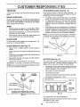
Mow up and down slopes, not across
Remove obstacles such as rocks, tree limbs, etc
•
•
Watch for holes, ruts, or bumps.
Uneven terrain could
overturn the machine
Talt grass can hide obstacles.
=
Use slow speed Choose a low gear so that you will not have
to stop or shift while on the slope.
•
Fot[ow the manufacturer's
recommendations
for wheel
weights or counterweights to improve stability
•
Use extra care with grass catchers or other attachments
These can change the stability of the machine.
•
Keep all movement on the slopes stowand gmduat Do not
make sudden changes in speed or direction.
•
Avoid starting or stopping on a slope, if tires lose traction,
disengage the blades and proceed slowly straight down the
slope.
DO NOT:
•
Never carrychildren.They may fall
offand be seriously
injured or interfere with safe machine operation_
Never allow children to operate the machine.
Use extra care when approaching blind corners, shrubs,
trees, or other objects that may obscure vision
OPERATION
•
•
•
•
DO:
•
Before and when backing, look behind and down for small
children
•
Slopes are a ma or factor related to loss-of-control and tipover
accidents, which can resu t n severe njury or death. A s opes
require extra caution. Ifyou cannot back up the slope or if you feel
uneasy on it, do not mow it.
•
•
•
•
*
Mow only in daylight or good artificial light
Do not operate the machine while under the influence of
alcohot or drugs
Watch for traffic when operating near or crossing roadways
Use extra care when loading or unloading the machine into
a trailer or truck
Keep children out of the mowing area and under thewatchfut
care of another responsible adult
Be alert and turn machine off if children enter the area
•
°
Keep nuts and bolts, especially blade attachment bolts, tight
and keep equipment in good condition
Never tamper with safety devices_ Check their proper
operation regularly.
Keep machine free of grass, leaves, or other debris build-up
Clean oil or fuel spillage
Allow machine to cool before
storing
Stop and inspect the equipment if you strike an object
Repair, if necessary, before restarting
Never make adjustments or repairs with the engine running
Grass catcher components are subject to wear, damage, and
deterioration, which could expose moving parts or allow
objects to be thrown. Frequently check components and
replace with manufacturer's recommended parts, wizen necessary
Mower bEades are sharp and can cut Wrap the blade(s) or
wear gloves, and use extra caution when servicing them
Check brake operation frequently
Adjust and service as
required
&
Donotturnonslopesunlessnecessary,
andthen, turnslowly
and gradually downhill, if possible
Do not mow near drop-offs, ditches, or embankments
The
mower could suddenly turn over if a wheel is over the edge
of a cliff or ditch, or if an edge caves in.
Do not mow on wet grass_ Reduced traction could cause
sliding,
Do not try to stabilize the machine by putting your foot on the
ground
Do not use grass catcher on steep slopes
&
2
Look for this symbol to point out important safety precautions,
tt means
CAUTION!!! BECOME ALERT!!! YOUR
SAFETY IS INVOLVED.
CAUTION:
Always disconnect spark
plug wire and place wire where it cannot
contact spark plug in order to prevent
accidental starting when setting up,
transporting,
adjusting
or making
repairs.
PRODUCT
CONGRATULATIONS
on your purchase ef a Sears
Tractor.. It has been designed, engineered and manufactured to give you the best possible dependability and
performance,.
Should you experience any problem you cannot easily
remedy, please contact your nearest Sears Authorized
Service Center/Department.
We have competent, welltrained technicians and the proper tools to service or repair
this unit..
Please read and retain this manual. The instructions will
enable you to assemble and maintain your unit properly.
Always observe the "SAFETY RULES"°
MODEL
NUMBER
917.255981
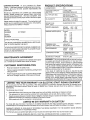
SPECIFICATIONS
HORSEPOWER:
18 0
GASOLINECAPACITY
AND TYPE:
3 5 GALLONS
UNLEADED REGULAR
OtLTYPE
SAE 30 (above 32°F)
SAE 5W-30 (below 32°F)
(API-SG):
OILCAPACITY:
W/FILTER:
W/O FILTER:
SPARK PLUG:
(GAP: ..025")
CHAMPION RV15YC
VALVE CLEARANCE:
INTAKE:
EXHAUST:
GROUND SPEED (MPH):
Forward
1st
2nd
3rd
4th
5th
6th
Reverse
SERIAL
NUMBER
DATEOFPURCHASE
THEMODELANDSERIALNUMBERSWILLBEFOUND
ON A PLATE UNDER THESEATo
YOU SHOULD RECORD BOTH SERIAL NUMBER AND
DATE OF PURCHASE AND KEEP IN A SAFE PLACE
--OR FUTURE REFERENCE..
MAINTENANCE
AGREEMENT
A Sears Maintenance
Agreement
uct. Contact your nearest Sears
CUSTOMER
RESPONSIBILITIES
Read and observe
the safety
•
FolIow a regular schedule
using your unit.
-
Fellow the instructions
under"Customer
Responsibili
ties" and "Storage" sections of this owner's manual,.
i,,1111
rules..
in maintaining,
caring for and
, I'"IHI
075
1 50
2 50
150
3.5O
5.75
2.25
TRANSAXLE OIL
CAPACITY AND TYPE:
4 QUARTS
SAE 30 APFSG
TIRE PRESSURE:
FRONT:
REAR:
CHARGING SYSTEM:
3 AMPS BATTERY
15 AMPS HEADLIGHTS
BLADE BOLT TORQUE:
30_35 FT LBS
_
I I'11111
LIMITED TWO YEAR WARRANTY
003" - 006"
.016" - 019"
14 PSI
10 PSI
WARNING: This unit is equipped with an internal combustion engine and should not be used on or near any unimproved forest-covered, brush-covered or grass-covered
land unless the engine's exhaust system is equipped with
a spark arrester meeting applicable local or state laws (if
any). if a spark arrester is used, it should be maintained in
effective working order by the operator,.
In the state of California the above is required by law
(Section 4442 of the California Public Resources Code).
Other states may have similar laws. Federal laws apply on
federal lands. A spark arrester for the muffler is available
through your nearest Sears Authorized Service Center/
Department (See REPAIR PARTS section of this manual).
is available on this prodstore for details.
•
4.0 PINTS
35 PINTS
"11 "
ON ELECTRIC
START RIDING EQUIPMENT
For two (2) years from the date of purchase, if this riding equipment is maintained, lubricated and tuned up according to the
instructions in the owner's manual, Sears wiil repair or replace, free of charge, any parts found to be defective in material or
workmanship.
This Warranty does not cover:
o
°
•
o
Expendable items which become worn during normal use, such as blades, spark plugs, air cleaners and belts.
Tire replacement or repair caused by punctures from outside objects, such as nails, thorns, stumps, or glass
Repairs necessary because of operator abuse, negligence, improper storage or accident or the failure to maintain the
equipment according to the instructions contained in the owner's manual
Riding equipment used for commercial or rentat purposes.
LIMITED
90 DAY WARRANTY
ON BATTERY
For ninety (90) days from date of purchase, if any battery included with this riding equipment proves defective in material or
workmanship and our testing determines the battery will not hold a charge, Sears wilt replace the battery at no charge
WARRANTY SERVICE
CENTER/DEPARTMENT
IS AVAILABLE BY RETURNING
IN THE UNITED STATES.
THE RIDING EQUIPMENT
TO THE NEAREST
SEARS SERVICE
This Warranty gives you specific legal rights, and you may also have other rights which may vary from state to state
SEARS,
ROEBUCK
i
AND CO., D/817 WA, HOFFMAN
i ,11,1,,i
3
ESTATES,
ILLINOIS
60179
i .n
...i.....
, ...
i ..
_l.u.......
,"' 'u
,.vnnl i ..
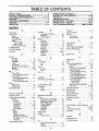
"fABLE OF CONTENTS
..nn
ul.
,111,11
i ..............................
SAFETY RULES ............................................................
2
PRODUCT
SPECIFICATIONS
......................................
3
CUSTOMER
RESPONSIBILITIES
.....................
3, 16-18
WARRANTY
..................................................................
3
TRACTOR
ACCESSORIES
..........................................
5
ASSEMBLY
..............................................................
7-10
OPERATION
.............................
_............................
11-14
.u,H
i
_.r.................... i.ll
i
ir'm.,i
ii
nl
MAINTENANCE
SCHEDULE
......................................
15
SERVICE AND ADJUSTMENTS
............................
19-25
STORAGE
...................................................................
26
TROUBLESHOOTING
...........................................
27-28
REPAIR PARTS - TRACTOR
................................
31-47
REPAIR PARTS - ENGINE ....................................
48-57
PARTS ORDERING/SERVICE
................ BACK COVER
JNDE×
A
Accessories ................................................. 5
Adjustments:
Brake ................................................. 21
Carburetor ....................................
25
Gauge Wheels ................................. 13
Mower
Front-To-Back ............................ 20
Side-To-Side ........................... 19
Throttle Control Cable .................... 25
Air Filter, Engine .........................................18
Air Screen, Engine ................................. 18
Assembly ............................................. 7-10
B
E
Operation ............................................ 1lq4
Electrical:
Operating Mower ................................
13
lntedocks and Relays ................... 23
Options:
Schematic ...................................... 30
Accessodes ..................................... 5
Wiring Diagram ............................ 32
Spark Attester ........................... 3,40
Engine:
Air Filter .......................................... 18
P
Air Screen .................................... 18
Pa_king Brake ................................... 11-12
Cooling Fins ......................................
18
PartsBag ...................................
6
Oil Change .........................................17
Oil Level ........................................
17
Parts, Replacement/Repair,.
31-47
Oil Type ........................................ 13,17
Product Specifications ............................... 3
Preparation ...................................... 13
Repair Parts ............................... 48-57
R
Starting .......................................... I4
Repair Parts ....................................... 31-47
Storage .................................................
26
.............
Battery:
Charging .......................................... 8
Cleaning ............................................. 18
Installation ............:........................... 10
Levels ............................................ 8,t 6
Preparation ....................................... 8
Starting with Weak Battery ..............23
Storage .......................................... 26
Terminals ....................................... 16
Bell:
Motion Drive
Removal/Replacer[lent
..............22
Mower Drive
Removal/Replacement
............ 20
Mower Blade Drive
Removal/Replacement
............. 21
Blade:
Sharpening ........................................ t6
Replacement ................................. t6
Brake Adjustment ................................ 21
S
F
Safety Rules ............................................... 2
Filter:
Seat
Air Filter ...........................................
18
Fuel ................................................ 18
Service and Adjustments
19°25
Oil .........................................................18
Carburetor ..................................... 25
Fuel:
Fuse ....................................................23
Hood Removal/Installation
..............24
Storage ............................................ 26
Motion Drive Beit
Type ..............................................
13
Removal/Replacement
........... 22
Fuse ......................................................... 23
Mower Drive Belt
Removal/Replacement
............ 20
H
Mower Blade Drive Belt
Headlights ............................................
23
Remova!/Replacement
...............21
Hood Removal/Installation
.....................24
MowerAdjustment
Front4o-Back ......................... 20
L
Side-to-Side .............................. 19
Mower RemovaIllnstallation
......... lg
Leveling Mower Deck
19
Tire Care ................................. 8,t 5,23
Lubrication:
Slope Guide Sheet ................................. 59
Ohart .............................................
15
Spark Piug(s) ..............................................18
Engine ...........................................
17
C
Specifications
3
CarburetorAdjustment
........................ 25
Starting the Engine ...............................
13-14
Maintenance Schedule ........................... 15
Controls, Tractor .................................. 1 I
Steering Wheel .........................................
7,22
Mower:
Customer Responsibilities .................16-18
Stopping the Tractor ...................................
12
Adjustment, Front-to-Back ........... 20
Engine:
Storage
26
Air Filter. ........................................ 18
Adjustment, Side-to-Side .............
19
Air Screen ................................... 18
Blade Replacement .........................21
T
Blade Sharpening ......................... 16
Cooling Fins ............................... 18
Throttle
Control
Cable
Adjustment ......
25
Cutting Height ................................. 12
Engine Oil .,_;....................... 13,18
Installation ...................................... t9
Fuel Filter ................................. t8
Tires .................................................. 8,16,23
Operation
13
Spark Plug(s) ............................ t8
Troubleshooting Chart ...................... 28-29
Removal ........................................ 19
Tractor:
Transaxle ................................................ 17
Battery .......................................
16
Mowing Tips ........................................
14
Blade ...........................................
16
Muffler ..................................................
18
W
Lubrication Chart ....................... 17
Spark
Arrester
............................
3,40
Maintenance Schedule ............. 15
Warranty ...................................
3
..................................................................
8
...................
..........................
...............................................
............................................................
.......................................
Tire Care .......................... 8,16,23
Transaxle ...................................... 17
Cutting Height, Mower ........................... 12
O
Oil:
Wiring Diagram ....................................... 32
Wiring Schematic
30
.......................................
Cold Weather Conditions ........ 13,17
Engine ............................................. 17
Storage
26
.........................................
4
iiiiil,llr
i IIIIHI'I'
'1....
II,
AND ATTACHMENTS
i,i ......................
,11,1,
,i
These accessories
and attachments
we re available through most Sears retail outlets and service centers
Most Sears stores can order these items for you when you provide the model number of your tractor.
MAINTENANCE
ENGINE
"_sPABK PLUG
when the tractor was purchased
GAS CAN
ENGINE OIL
FUEL STABILIZER
BLADES
BELTS
PERFORMANCE
Sears offers a wide variety of attachments that fit your tractor.. Many of these are listed below with brief explanations of how they can help
you This list was current at the time of publication however, it may change in future years - more attachments may be added, changes
may be made in these attachments, or some may no longer be available or fit your model r Contact your nearest Sears store for the
accessories and attachments
that are available for your tractor,
Most of these attachments do not require additional hitches or conversion kits (those that do are indicated) and are designed for easy
attaching and detaching
AERATOR promotes deep root growth for a heatthy lawn Tapered
2 5-inch steel spikes mounted on 10-inch diameter discs puncture
holes in soil at close Intervalsto Iet moisture soak in. Steel weight tray
for increased penetration
BUMPER protects front end of tractor from damage
CARTS make hauling easy. Variety of sizes available, ptus accessodes such as side panel kits, toot caddy, cart cover, protective mat and
dolly.
CORING AERATOR takes small plugs out of soil to atlow moisture
and nutrients to reach grass roots. 36-inch swath. 24 hardened steel
coring tips. 150 Ib capacity weight tray
DISC HARROW has 2 gangs of 4 steel blades that angle from 10 to
20 degrees, 40 inches wide. Can hook 2 units in tandem (Requires
sleeve hitch-)
DOZER BLADE removes snow; grades dirt, sand and gravel. 48
inches wide, 17 incheshigh, clears 44-inch path when angled Master
lift control lever for operator ease Spring trip for snow removal on
uneven pavement; bui[tqn float for blade to follow ground contour.
Reversible, repfaceable scraper bar (Use with tire chains and wheel
weights and/or rear drawbar weight )
EASY OIL DRAIN VALVE makes oil changes easier, faster
FRONT END LOADER system includesdoubte wide rear tires, rear
weight box, and hydraulically operated 5 26 cu.ft bucket
FRONT NOSE ROLLER canters in front of mower deck to reduce
chances of "scalping" on uneven terrain
GANG HITCH lets you tow 2 or 3 putt-behind attachments at
once, such as sweepers, dethatchers, aerators (not for use with
rollers, carts or other heavy attachments)
MULCH RAKE/DETHATCHER loosens soil and flips thatch and
matted Ieaves to lawn surface for easy pickup Twenty spring line
teeth Usefuf to prepare bare areas for seeding. Available for front or
rear mounting. HIGH PERFORMANCE REEL-ACTION SPRING
TINE DETHATCHER covers 36-inch wide path and tossesthatch into
large hopper. Mounts behind tractor
PLOW turns soif 6 inches deep, cuts 10-inch furrow Crank adjustment controls depth, 3-position yoke sets width. Heavy steel landside
for straight furrowing (Requires sleeve hitch )
RAMP TOPS AND FEET let you load and unload tractor from a
pickup truck Use with 2 x 8 or 2 x 10 lumber
REAR GRADER BLADE is 42 incheswide and operated from driver's
seat. Reversible steel blade can be angled at 30 degrees for grading
Reverses for pushing snow backwards. (Requires sleeve hitch.)
ROLLER for smoother lawn suflace. 36-inch wide, 18-inch diameter
water-tight drum holds up to 390 tbs. of weight. Rounded edges
prevent harm to turf Adjustable scraper automatically cleans drum.
SLEEVE CULTIVATOR
is 43 inches wide. Prepares
ground for
seeding, helps weed control. Steel frame hotds 5 adjustable sweeps.
Adjusts vertically, horizontally
(Requires sleeve hitch ) Optional
accessory:
steef furrow opener for wider openings for potatoes,
corn, and other deep-seeded
crops
SLEEVE HITCH for use with master lfft system
uncouples.
Single pin couples/
SNOWTHROWER
has 40-inch swath,
Drum-type auger handles
powdery and we'Jheavy s now Mounts easily with simple pin arrangement. Discharge chute adjusts from tractor seal
6-inch diameter
spout discharges snow 10 to 50 feet Lift controlled at tractor seat
(Use with chains and wheel weights and/or rear drawbar weighL)
SPRAYERS
use 12-vott DC electric motor that connects
to the tractor
battery or other 12-veil source,
Includes
booms for automatic
spraying and hand held wand for spot spraying. Wand has adjustable
spray pattern
For applying herbicides, insecticides, fungicides and
liquid fertilizers
SPREADER/SEEDERS
make seeding, fertilizing, and weed killing
easy. Broadcast spreaders are also useful for granular de-icers and
sand
SWEEPERS
let you collect grass clippings
and leaves
TILLER has 8 hp engine to prepare seed beds, cultivate, and compost
garden residue, Chain-drive transmission
Six 11-inch diameter one
piece heat-treated steel tines, Tills 30-inch path, (Requires sleeve
hitch ,) Or use 5 hp tow-behind TILLER with 36-inch swath to prepare
seed beds, cu!livate and compost garden residue. Tiller has its own
built-in lift and depth control system and does NOT require a sleeve
hitch Fits any lawn, yard or garden tractor
Simply hook up to the
tractor drawbar and go! Optional
accessories
for 5 hp tiller convert
unit for dethatching, aerating, hilling
without tools
TIRE CHAINS are heavy duty; closely spaced
give smooth ride, outstanding traction
extra-large
cross links
TRACTOR CAB has heavy duty vinyi fabric over tubular steel frame,
ABS p_astic top; clear plastic windshield offers 360 degree visibility
Hinged metal doors with catch,
Keeps operator warm and dry
Remove vinyl sides and windshields
for use as sun protector in
summer,
Optional
accessories
include:
tinted/tempered
solid
safety glass windshield
with hand operated wiper; 12-volt amber
caution light for mounting on cab top,,
VACS for powerful collection of heavy grass clippings and leaves
Optional wand attachment
to pick up debris in hard-to-reach
places
VACICHIPPER
includes a chipper-shredder
WEIGHT BRACKET for drawbar for snow removal applications.
Can
be mounted on front of tractor for p_owing applications
Uses (1) 55
lb weight
WHEEL WEIGHTS for rear wheels
remova! or dozing heavy materials
provide
needed traction
for snow
H..II..I
......................
, ,,!ll '
,1""'11"11"11
I....
H.. i
.
CONTENTS
==.... _1
......
.....
OF HARDWARE
I1
I1'
'I
H"
I
shown full size
,
.
..11...i
PACK
.....II '
............................. H,,=..I.=
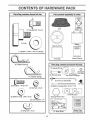
Parts Bag contents
H.
'"....
r',',"
...=
................
Parts packed separately in carton
÷
Seat
Battery acid
(1) Shoulder Bolt 5/16-18
(I) Knob
Battery
Steering Wheel
(1) Washer t7/32 x 1-3/16 x 12 Gauge
,,.,H.=.1.1.i"11'1'
"111'.1.. i '
i
Owner's Manual
Parts Bag
'IH,'NI '1 I
(3) Retainer Springs
Parts bag contents
not shown full size
(2) Gauge Wheels!_
(2) Crown
(2) Washers
(2) Shoulder Bolts
Lock Nuts
3/8 x 3/4 x 14 Gauge
(4) Retainer Springs
i
H.
,H..iii1., i
ii
i
_-----_°_,
(2) Hex Bolts 1/4-20 x 3/4
_ _ _
_
,_
(2) Battery Carriage Bolts 1/4-20 x 7-1/2
(2) Hex Nuts 1/4-20
(2) Washers 9/32 x 5/8 x 16 Ga,
®
(2) Lock Washers 1/4
(2) Wing Nuts 1/4-20
6
(2) Keys
i=,1
"='H",H .................
LY
i
,,
H =1,=,=,,=1,=
i
,1111=
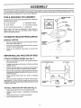
Your new tractor has been assembled at the factory with exception of those parts left unassemb}ed for shipping purposes.
To ensure safe and proper operation of your tractor alt parts and hardware you assemble must be tightened secure[yo Use
the correct tools as necessary to insure proper tightness
TOOLS
REQUIRED
FOR ASSEMBLY
STEERING
A socket wrench set wiII make assembly easier° Standard
wrench sizes are tisted.
(2) 7/16" wrenches
(1) Adjustable wrench
(1) 9/16" wrench
(1) Tire pressure gauge
(1) 3/4" socket w/drive ratchet
(1) Utility knife
When right or left hand is mentioned in this manual, it
means when you are in the operating position (seated
behind the steering wheel)
WHEEL
'_ INSERT
FLAT
WASHER
STEERING
__1__
-'_
TO REMOVE TRACTOR FROM CARTON
UNPACK
CARTON
o
Remove all accessible loose parts and parts cartons
from carton (See page 6).
=
Cut, from top to bottom, along lines on all four corners
of carton, and lay panels flat.
=
Check for any additional
remove°
STEERING
SHAFT
WHEEL
STEERING
__
ADAPTER
t
•/i
. :S ;_:."_
loose parts or cartons and
t, ¸
!
I
/
/
!
/
BEFORE ROLLING TRACTOR OFF SKID
ATTACH
,
•
•
STEERING
WHEEL
Remove hex bolt, lock washer and large flat washer
from steering shaft.
Position front wheels of the tractor so they are pointing
straight forward.
Position steering wheel so cross bars are horizontal
([eft to right) and slide onto steering wheel adapter_
o
Secure steering wheel to steering shaft with hex bolt,
lock washer and large flat washer previously removed.
Tighten securely.
o
Snap steering
wheel
CLUTCH/BRAKE
PEDAL
LIFT LEVER
wheel insert into center of steering
,
Remove protective plastic from tractor hood and grill..
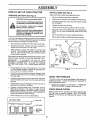
IMPORTANT: CHECK FOR AND REMOVE ANY STAPLES
iN SKiD THAT MAY PUNCTURE TIRES WHERE UNiT IS
TO ROLL OFF SKID
TO ROLL TRACTOR
OFF SKID (See Fig. 2)
o
Raise attachment lift lever to its highest position.
•
Release parking brake by depressing clutch/brake
pedal..
Place gearshift lever in neutral (N) position°
Roll unit backwards off skid.
•
=
FIG. 1
(See Fig. 1)
GEARSHIFT
LEVER
FIG, 2
,
INSTALL
PREPARE
BATTERY
SEAT (See Fig. 4)
Adjust seat before tightening adjustment knob.
(See Fig. 3)
o
o
Remove cardboard packing on seat pan,
Place seat on seat pan and assemble shoulder bolt.
Wash hands or clothing immediately if
accidentally in contact with batteryacid.
.
Assemble adjustment
Do not tighten°
Do not smoke. Fumes from charged
battery acid are explosive.
°
Tighten shoulder' bolt securely°
•
Lower seat into operating position and sit on seat.
Read the instructions included with the
battery vent caps. Alwayswear gloves,
clothing and goggles to protect your
hands, skin and eyes.
o
Slide seat until a comfortable position is reached which
allows you to press clutch/brake pedal all the way
down.
=
Get off seat without moving its adjusted position_
=
Raise seat and tighten adjustment knob securely.
.......
=
CAUTION:
,11, i,
Wear eye and face shield.
i
ii
knob and flat washer loosely,
iiii,
Your unit has a battery charging system which is sufficient
for normal use. However, periodic charging of the battery
with an automotive charger will extend its life.
.
-
See instructions packed with vent caps in parts bag.
Fill battery with acid. Fitl each cell until it reaches the
bottom of the vent wells° Do not overfill
•
Allow battery to stand and settle for at least thirty
minutes
After standing, check the battery cell acid
level, if below the vent wells, add more acid until the
correct level is reached°
While battery is standing (after adding acid) and later, while
battery is being charged, continue with assembly of unit.
IMPORTANT:
TO MAXIMIZE THE LIFE OF YOUR
BATTERY, IT IS NECESSARY THAT THE BATTERY BE
CHARGED
BEFORE USE FAILURE TO CHARGE
BATTERY CAN RESULT IN A SHORTENED BATTERY
LIFE.
-
Charge battery at a rate of 6 amperes for' 1 hour. Use
a 12 volt battery charger. Observe all safety precautions required for battery charging°
•
Check the acid level after the battery is charged, If the
acid has fallen below the correct level, add distilled or
iron free water,
°
Install the vent caps to cover the vent wells. Wash the
top of the battery with water' to remove any acid, then
wipe dry,
o
Check battery case for leakage to make sure that no
damage has occurred in handling
•
Dispose of excess battery acid. Neutralize acid for
disposal by adding it to two gallons of water in a five
gallon plastic container. Stir' with a wooden or plastic
paddle while adding baking soda until the addition of
more soda causes no more foaming.
•
Follow instructions
FIG, 4
CHECK
y
PRESSURE
The tires on your unit were overinflated at the factory for
shipping purposes° Correct tire pressure is important for
best cutting performance,
o
Reduce tire pressure to PSI shown in "PRODUCT
SPECIFICATIONS" on page 3 of this manual.
CHECK
BRAKE
SYSTEM
After you learn 5ow to operate your tractor, check to see
that the brake is properly adjusted_ See "TO ADJUST
BRAKE" in the Service and Adjustments section of this
manual
on how to install battery,
CUT AWAY VIEW
TIRE
VENTCAP
WELL
BATTERY
CELL ACID
LEVEL
FIG. 3
8
_11,=
,,J i
ASSEMBLY
iii
i,.11,,.11, ,i,i,
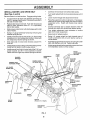
INSTALL
i.....................................
MOWER
AND DRIVE BELT
i
i,
,
•
Carefully remove block from behind idler pulley,,
•
Turn height adjustment knob counterclockwise
stops,
o
Lower mower linkage with attachment lift lever°
-
Relieve idler tension from belt. Push idler forward and
place a block (standard wood 2 x 4 or equivalent)
behind idler pulley°
Place the suspension arms on deck pins,, tf necessary,
raise front of mower to align deck pins with the holes in
suspension arms,. Retain with double loop retainer
springs,,
o
Slide mower under tractor with discharge guard to right
side of tractor.
Connect anti-sway bar to chassis bracket under left
footrest and retain with double loop retainer spring,
°
o
Swing L, Hogauge wheel bar forward by removing rear
retainer spring and pin°
Turn height adjustment knob clockwise
slack from mower suspension.
°
Raise deck to highest position,
•
Install one front link in top hole of the L.H. front mower
bracket and LHo front suspension bracket, Retain with
two single loop retainer springs as shown°
•
Swing Loll. gauge wheei bar back towards rear of
mower and secure with pin and retainer spring removed eadier.
,,
Slide right side of mower deck forward, toward R.H.
front tire,
.
Assemble gauge wheets as shown using long shoulder
bolts, 3/8 washers and nuts, Tighten securely.,
o
Checkbelt for proper routing in all mowerpulleygrooves,
Install belt into electric clutch pulley groove.
.
Adjust gauge wheels before operating mower as shown
in the Operation section of this manual.
.
Install second front link in the top hole of the RH front
mower bracket and R.H front suspension bracket°
Retain with two single loop retainer springs as shown,
(See Figs. 5 and 8)
Be sure tractor is on level surface, Engage parking brake
o
Cut and remove tie down wire between anti-sway bar
and R.H gauge wheel bracket. Swing anti-sway barto
left side of mower deck,,
.
o
SUSPENSION
ARMS
CHASSIS
BRACKET
to remove
FRONT
SUSPENSION
BRACKET
ELECTRIC
CLUTCH
PULLEY
DOUBLE LOOP
RETAINER SPRING
DOUBLE LOOP
RETAINER SPRING
FRONT
LINKS
until it
LH. GAUGE
WHEEL BAR
FRONT
SUSPENSION
BRACKET
SINGLE
LOOP RETAINER
SPRINGS
SHOULDER
BOLT
MOWER
BRACKET
NUT
ANTI-SWAY
BAR
318 WASHER
IDLER
PULLEY
GAUGE
WHEEL
BLOCK
(Wood 2 x 4 or equiv,)
DISCHARGE
GUARD
9
CHECK DECK LEVELNESS
''":_
"-- ......
;_
FLAT WASHER
For best cutting resuits, mower housing should be properly
Ieveledo See "TO LEVEL MOWER HOUSING" in the
Service and Adjustments section of t his manual.
CHECK
BELTS
FOR PROPER
POSITION
OF ALL
See the figures that are shown for replacing motion, mower
drive, and mower blade drive belts in the Service and
Adjustments section of this manual. Verifythat the belts are
routed correctly.
INSTALL
BATTERY
OLAOKOAO
(See Figs. 6 and 7)
i
CAUTION: Do not short battery terminals. Before Installing battery, remove
TERMINAL
ACCESS
DOORS
BATTERY
rings,
metal etc.
bracelets, wristwatch bands,
Positive terminal must be connected
first to prevent sparking from accidental grounding.
CAPS
iii1,,11,1111
i,i,
'BATTERY
-
Lift hood to raised position..
°
Be sure battery drain tube has not come foose and is
securely attached to drain in battery tray.
o
Lower' battery into battery tray with terminals to front of
tractor°
-
First connect RED battery cable to positive (+) battery
terminal with hex bolt, flat washer, Iockwasher and hex
nut as shown Tighten securely.
=
Connect BLACK grounding cable to negative (-) battery
terminal with remaining hex bolt, fiat washer, lock
washer and hex nut. Tighten securely.
TRAY
KEYHOLE
FIG. 7
v" CHECKLIST
BEFORE YOU OPERATE AND ENJOY YOUR NEW
TRACTOR, WE WISH TO ASSURE THAT YOU RECEIVE
THE BESTPERFORMANCE AND SATISFACTION FROM
THIS QUALITY PRODUCT
PLEASE REVIEW THE FOLLOWING
CHECKLIST."
=
Slide the two battery bolts through the terminal guard
and start the wing nuts onto the threads.
,/
All assembly instructions have been completed.
,/
No remaining loose parts in cartonu
•
Position terminal guard over battery as shown lower
battery bo ts nto key holes and slide square shafts of
battery bolts into slots of key holes..
v"
Battery is properly prepared and charged°
1 hour at 6 amps)o
.
Tighten wing nuts by hand making sure battery bolts
remain in slots of the key holes in the battery support,
Be sure terminal access doors are closed.
,/
Seat is adjusted comfortably
,/
All tires are properly inflated. (For shipping purposes,
the tires were overinflated at the factory).
,1'
Be sure mower deck is properly leveled side-to-side/
front-to-rear for' best cutting results. (Tires must be
properly inflated for leveling).
v'
Check mower and drive belts. Be sure they are routed
properly around pulleys and inside all belt keepers.
,/
Check wiring. See that all connections are still secure
and wires are properly clamped.
°
Use terminal access doors for:
o
Inspection for secure connections
ware).
•
Inspection for corrosion.
=
Testing battery
o
Jumping (if required)_
•
Periodic charging.
(to tighten hard-
(Minimum
and tightened securely,
WHILE LEARNING HOW TO USE YOUR TRACTOR, PAY
EXTRAA TTENTION TO THE FOLLOWtNG IMPORTANT
ITEMS:
10
v"
Engine oil is at proper level.
,/
Fuel tank is filted with fresh, clean, regular unleaded
gasoline.
,,/
Become familiar with all controls - their location and
function. Operate them before you start the engine,
v'
Be sure brake system is in safe operating condition,
ii
,,
iii1,11111iii
i
iiii
,11,11
,i
OPERATION
KNOW YOUR TRACTOR
READ THIS OWNER'S
MANUAL
AND SAFETY
RULES BEFORE
OPERATING
YOUR TRACTOR.
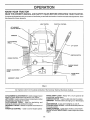
Compare the i11ustrations with you r tractor to familiarize yourself with the location of various controls and adjustments
this manual for future reference_
LIGHT SWITCH
THROTTLE
Save
CONTROL
ATTACHMENT
CLUTCH SWITCH
AMMETER
CLUTCHIBRAKE
PEDAL
LIFT LEVER
/
IGNITION SWITCH
CHOKE CONTROL
PARKING
LEVER
BRAKE
HEIGHT ADJUSTMENT
KNOB
RANGE SHIFT
LEVER
GEARSHIFT
LEVER
FIG. 8
Our tractors conform to the safety standards of the American National Standards lnstitute_
RANGE SHIFT LEVER - Allows "HI" or "LO" speed for all
forward and reverse gears,
IGNITION SWITCH - Used to start and stop the engine.,
AMMETER - indicates battery charging (+) or discharging
ATI'ACHMENT CLUTCH SWITCH - Used to engage mower
blades or other attachments mounted to your tractor°
LIFT LEVER- Used to raise and lower mower deck or other
attachments mounted to your tractor,
CLUTCH/BRAKE
PEDAL - Used for declutching and
braking the tractor and starting the engine.
GEARSHIFT LEVER -SeIects the speed and direction of
tractor.
THROTTLE CONTROLUsed to control engine speed
(-),
LIGHT SWITCH _Turns the headlights on and ofL
PARKING BRAKE LEVER- Locks clutch/brake pedal into
the brake position.
CHOKE CONTROL - Used when starting a cold engine_
HEIGHT ADJUSTMENT KNOB- Used to adjust the mower
heighL
11
,
,u
....
•.........................
,,,i, i,
,,.,
OPERATmON
, u,ll,,
u
u,l_m,
=_
The operation of any tractor can result in foreign objects thrown into the eyes, which can
result tn severe eye damage. AlWays wear safety glasses or eye shields while operating your
tractor or performing any adjustments or repairs. We recommend a wide vision safety mask
for over the spectacles or standard safety glasses.
,,u,
HOW TO USE YOUR TRACTOR
pletely, as described above, before leaving
the operator's
to empty
CAUTION:
Always position;
stop tractor
comgrass catcher, etc.
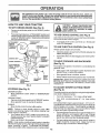
TO SET PARKING BRAKE (See Fig. 9)
,
Depress clutch/brake
and hold.
o
i,,, ,i ....
pedal into full "BRAKE" position
i
Place parking brake lever in"ENGAGED" position and
release pressurefrom clutch/brake pedal Pedal should
remain in "BRAKE" position. Makesure parking brake
will hold vehicle secure.
ATTACHMENT
CLUTCH
TO USE CHOKE
(See Fig. 9)
Use choke control whenever you are starting a cold engine.
Do not use to start a warm engine
o
"DISENGAGED"
swrrcH
"ENGAGED"
POSITION
CONTROL
THROTTLE
CONTROLLEVER
To engage choke control, pull knob out. Slowly push
knob in to disengage.
TO USE THROTTLE
CONTROL;
(See Fig. 9)
Always operate engine at full throttle.
PARKING
BRAKE
"ENGAGED"
POSITION
IGNITION
CHOKE
Operating engine at less than futl throttle reduces the
battery charging rate_
o
Full throttle offers the best bagging and mower performance.
TO MOVE FORWARD
AND BACKWARD
(See Fig. 9)
CLUTCH/BRAKE
PEDAL "BRAKE"
POSITION
"DRIVE"
POSITION
o
The direction and speed of movement
gearshift lever.
HEIGHT
ADJUSTMENT
KNOB
GEARSHIFT
LEVER
RANGE
SHIFT
LEVER
is controlled by the
°
Start tractor with clutch/brake pedal depressed and
gearshift lever' in neutral (N) position.
=
Move gearshift lever to desired position.
o Slowly release clutch/brake pedalto start movement.
IMPORTANT: BRING TRACTOR TO A COMPLETE STOP
BEFORE SHIFTING OR CHANGING GEARS. FAILURE
TO DO SOWtLLSHORTENTHEUSEFUL
LIFE OF YOUR
TRANSAXLE.
FIG, 9
STOPPING
TO ADJUST
(See Fig. 9)
(See Fig. 9)
MOWER BLADES o Move attachment
position,
Depress clutch/brake pedal intofutI"BRAKE" position_
Move gearshift lever to neutral (N) position.
Move throttle control to sfow (,_)
position.
NOTE:
Failure to move throttIe control to slow (,_)
position and allowing engine to idle before stopping may
cause engine to "backfire".
,
o
Turn ignition key to "OFF" position and remove key,
Always remove key when leaving tractor to prevent
unauthorized use.
Never use choke to stop engine.
NOTE: Under certain conditions when tractor is standing
idle with the engine running, hot engine exhaust gases may
cause "browning" of grass, To eliminate this possibility,
always stop engine when stopping tractor on grass areas.
HEIGHT
•
Turn knob clockwise (t_l)
to raise cutting height.
o
Turn knob counterclockwise
height.
(P-_) to lower cutting
The cutting height range is approximately 1-1/4" to 4-1/4".
The heights are measured frem the ground to the blade tip
with the engine not running. These heights are approxF
mate and may vary depending upon soil conditions, height
of grass and types of grass being mowed=
ENGINE o
CUTTING
The cutting height is controlled by tu rning the height adjust _
ment knob in desired direction.
clutch switch to "DISENGAGED"
GROUND DRIVEo
o
MOWER
12
•
The average lawn should be cutto approximately2-1/2
inches during the cool season and to over 3 inches
during hot months. For healthier and better looking
lawns, mow often and after moderate growth
o
For' best cutting performance, grass over6 inches in
height should be mowed twice_ Make the first cut
relatively high; the second to desired height.
OPERATION
TO ADJUST
GAUGE
WHEELS
TO OPERATE
(See Fig. 10)
i,ul
....
ON HILLS
lU ..........
ilnlU,U,,nl,,i i
I
•
o
Adjust mower to desired cutting height.
Lower mower with lift control. Remove rear retainer
spring and clevis pin which secure each gauge wheel
,
Lower gauge wheels to ground. Raise gauge wheels
slightly to align holes in bracket and gauge wheel bar
and insert clevis pins Gauge wheels should be slightly
off the ground.
o
Choose the slowest speed before starting up or down
hills°
°
Avoid stopping or changing speed on hills
Replace retainer springs into clevis pins.
°
If slowing is necessary, move throttle control lever to
slower position.
o
If stopping is absolutely necessary, push clutch/brake
pedal quickly to brake position and engage parking
brake.,
hills with slopes
CAUTION:
Do not
greater
drive than
up or15down
° and
do not drive across any slope.
_;,_;
RETAINER
SPRING
_
!
•
Move gearshift lever to 1st gear and range shift lever to
low (L) position, Be sure you have allowed room for unit
to roll slightly as you restart movement,
•
To restart movement, slowly release parking brake and
clutchtbrake pedal
°
Make all turns slowly.
GAUGE
WHEEL BAR
GAUGE
WHEEL
,,U,l,nn
l
TO TRANSPORT
TO OPERATE
BRACKET
o
Raise attachment
ment lift control,
FIG. 10
-
When pushing or towing your tractor, be sure gearshift
lever is in neutral (N) position..
=
Do not push or tow tractor at more than five (5) MPH
MOWER
(See Fig. 8 and 9)
NOTE: To protect hood from damage when transporting
your tractor on a truck ora trailer, be sure hood is closed and
secured to tractor° Use an appropriate means of tying hood
to tractor (rope, cord, etco)..
Your tractor is equipped with an operator presence sensing
switch. Any attempt by the operator to leave the seat with
the engine running and the attachment clutch engaged will
shut off the engine,
BEFORE
o
°
Select desired height of cut,
Lower mower with attachment lift control,
•
Start mower blades by engaging attachment
control.
.
TO STOP MOWER BLADES _disengage attachment
clutch control
CHECK
clutch
I
CAUTION:
Do not operate the mower
without either the entire grass catcher,
on mowers so equipped, or the discharge guard in place.
lift to highest position with attach-
ENGINE
THE ENGINE
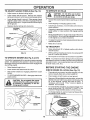
OIL LEVEL (See Fig, 12)
o
The engine in your tractor has been shipped, from the
factory, already filled with summer weight oil
o
Check engine oi! with tractor on level ground_
,
Remove oiffill cap/dipstick and wipe clean, reinsert the
dipstick and push it all the way down into the tube, wait
for a few seconds, remove and read oil level. If
necessary, add oil until "FULL" mark on dipstick is
reached. Do not overfill°
°
For cold weather operation you should change oil for
easier starting (See "OIL VISCOSITY CHART" in the
Customer Responsibilities section of this manual)..
•
To change engine oil, see the Customer Responsibilities section in this manual..
i
I
STARTING
ENGINE OIL
FILLER CAPIDIPSTICK
RUNNER
DISCHARGE
GUARD
FIG. 11
13
FIG. 12
ADD GASOLINE
MOWING
o
Fill fuel tank. Use fresh, clean, regular unleaded
gasoline. (Useof leaded gasoline will increasecarbon
and lead oxide deposits and reduce valve life)o
IMPORTANT: WHEN OPERATING IN TEMPERATURES
BELOW 32°F(0°C), USE FRESH, CLEAN WINTER GRADE
GASOLINE TO HELP INSURE GOOD COLD WEATHER
STARTING
WARNING:
Experience indicates that alcohol blended
fuels (called gasohot or using ethanol or methanol) can
attract moisture which leads to separation and formation of
acids during storage. Acidic gas can damage the fuel
system of an engine while in storage., To avoid engine
problems, the fuel system should be emptied before storage of 30 days or longer. Drain the gas tank, start the
engine and let it run until the fuel lines and carburetor are
empty. Use fresh fuel next season_ See Storage Instructions for additional information.
Never use engine or
carburetor cleaner products in the fue_ tank or permanent
damage may occur.
filler neck. Do not overfill. Wipe off any
CAUTION:
bottom
of gas
spilled oil or Fill
fuel.to Do
not store,
spilltank
or
use gasoline near an open flame.
TO START
ENGINE
=
Tire chains cannot be used when the mower housing
is attached to tractor..
,,
Mower should be properly leveled for best mowing
performance. See "TO LEVEL MOWER HOUSING" in
the Service and Adjustments section of this manual
•
Use the runner on the right hand side of mower as a
guide, The blade cuts approximately an inch outside
the runner (See Fig. 11)_
.
The left hand side of mower should be used for trimming..
°
Drive so that clippings are discharged onto the area
that has been cut. Have the cut area to the right of the
tractor_ This will result in a more even distribution of
clippings and more uniform cutting°
o
When mowing large areas, start by turning to the right
so that clippings will discharge away from shrubs,
fences, driveways, etc. After' one or two rounds, mow
in the opposite direction making left hand turns until
finished (See Fig. 13)_
•
If grass is extremely tall, it should be mowed twice to
reduce load and possible fire hazard from dried clippings. Make first cut relatively high; the second to the
desired height_
,,
Do not mow grass when it is wet. Wet grass witl plug
mower' and leave undesirable clumps. Allow grass to
dry before mowing.
o
Always operate engine at ful! throttle when mowing to
assure better mowing performance and proper discharge of material Regulate ground speed by selecting a low enough gear' to give the mower cutting
performance as wetl as the quality of cut desired°
•
When operating attachments, select a ground speed
that will suit the terrain and give best performance of
the attachment being used.
(See Fig, 9)
When starting engine for the first time or if engine has run
out of fuel, it wil! take extra cranking time to move fuel from
the tank to the engine
•
Depress clutch!brake
o
Place gearshift lever in neutral (N) position.
o
Move attachment clutch to "DISENGAGED"
pedal and set parking brake.
-
Pull choke control out to choke (t\1) position for cold
engine start For warm engine start do not use choke
control°
=
Move throttle control to midway between fast (.f_) and
slow (,_.) positions.
°
Insert key into ignition and turn key clockwise to"START'
position and release key as soon as engine starts. Do
not run starter continuously for more than fifteen
seconds per minute° if engine does not start after
several attempts, move throttle control to fast (,1_)
position, wait a few minutes and try again°
position_
o
When engine starts, slowly push choke control in.
o
Move throttle control to fast (.f_) position°
.
Allow engine to warm up for a few minutes before
engaging drive or' attachments.
TIPS
f
NOTE: If at a high altitude (above 3000 feet) or in cold
temperatures (below 32°F), the carburetor fuel mixture
may need to be adjusted for best engine performance. See
"TO ADJUST CARBURETOR" in the Service and Adjustments section of this manual.
FIG. 13
14
n,un,
.
.....
CUSTO
i1,1,,i,,,,i,,11,,,
u,
i,
,
MAINTENANCE
F,,L
iNO,,TES
ii
RESPONSIB L TIES
,
........
SCHEDULE
iiii
,llll,,inu,i u
.,___
'
_.,_ '._,e_
.n
1,,_o_
.........................
'f
........
AsYOU
COMPLETE
REGULAR SERVICE
;_./_ _._?_. _.<,_ _<,_._ _._._ _'4_
Check Brake Operation
Check Tire Pressure
= €,iieck for Loose Fasteners
T
Sharpen/Replace
Lubrication c"h'a'rt ............
T
Check Baiiery Level/Rech arg e
R
....
I
_'
_/'
_#'
DATES
.-.........i_
.......
_
_.__.
6#44 .....................
6/
....
_'
Clean Battery and Terminals
....
_#'
.......
6/
6/'
.........
,,,t
....AdJUSt Blade Belt(s) Tension
,
,
6/'5
Drive Be,[!,!,S,!
Te,nsion
Check Engine Oil Level
SERV{CE
...........
""Check Transaxte Cooling
AdjustMttion
;_u
'
_/
Mower Blades
C
0
_'
£,4_
6##s ........
_
,,Change Engine Oil
6/
_
,, _1,2,a
6/
i ........
E
N
G
,,,,C,!eanAir Filter
_2
Clean Air Screen
Inspect Mu'filer/Spark Arresier ........
.....................
_#'2
......
I
N
Replace Oil Filter (If equipped)
Clean
Engine coo!,!ng"F'ins
,,
I,
'.......
Replace.SPark Plug
! $##_t
_
_Rep!ace Air FiJter Paper Cartridge
RECOMiVlENDATIONS
6/'
All adjustments in the Service and Adjustments section of
this manual should be checked at least once each season_
Check
brake operation,
Check
tire pressure_
,
Check
for loose fasteners°
(_) FRONT WHE
BEARING ZERK
WHEEL (_)
BEARING ZERK
ENGINE (_)
G
TRANSAXLE
FLUID
oil level,
"
SPINDLE ZERK (_)
SECTOR GEAR
TEETH
EACH USE
,
(_) SPINDLE
(_) STEERING
Once a year you should replace the spark plug, clean
or replace air filter, and check blades and belts for
wear° A new spark plug and clean air filter assure
proper air-fuel mixture and help your engine run better
and last longer
engine
CHART
(_TIE ROD BALL JOINTS
Some adjustments will need to be made periodically to
properly maintain your tractor.
Check
3 - It equipped with oi_ fi_ter, change off every 50 hours
4 - Repiace blades mere often when mowing in sandy soil
5 - tf equipped with adjustable system
LUBRICATION
The warranty on this tractor does not cover items that have
been subjected to operator abuse or negligence.
To
receive full value from the warranty, operator must maintain
tractor as instructed in this manual.
BEFORE
"
6/
! - Change more often when operating under a heavy load or in high ambient temperatures
2 - Service more often when operating in dirty or dusty conditions
.
,
6/##2
Replace Fuel Filter
GENERAL
,
64_1_2
(_ SAE 30 MOTOR OIL API - SG
IMPORTANT:
DO NOT OIL OR GREASE THE PIVOT POINTS
WHICH HAVE SPECIAL NYLON BEARINGS
VISCOUSLUBRICANTS WILL ATTRACT
DUST AND DIRT THAT WILL SHORTEN
THE LIFE OF THE SELF-LUBRICATING
BEARINGS,
IF YOU
FEEL THEY MUST BE LUBRICATED,
USE ONLY A DRY, POWDERED GRAPHITE
TYPE LUBRICANT
SPARINGLY,
(_ GENERAL PURPOSE GREASE
(_) REFER TO CUSTOMER RESPONSIBILITIES "ENGINE" SECTION
(_) SPRAY SILICONE LUBRICANT (MOVE BOOTS TO LUBRICATE)
15
TRACTOR
TO SHARPEN
Always observe safety rules when performing any maintenance.
Care should be taken to keep the blade balanced, An
unbalanced blade will cause excessive vibration and eventual damage to mower and engine°
BRAKE
o
The blade can be sharpened with a file or on a grinding
wheel Do not attempt to sharpen while on the mower.
=
To check blade balance, you will need a 5/8" diameter
steel bolt, pin, or a cone balancer (When using a cone
balancer, follow the instructions supplied with balanGer).
o
OPERATION
If tractor requires more than six (6) feet stopping distance
at high speed in highest gear', then brake must be adjusted°
(See "TO ADJUST BRAKE" in the Service and Adjustments section of this manual)°
TIRES
BLADE
(See Fig. 15)
.
Maintain proper' air pressure in all tires (See "PRODUCT SPECIFICAT!ONS" on page 3 of this manual).
.
Keep tires free of gasoline, oit, or insect control chemicals which can harm rubber..
Slide blade on to an unthreaded portion of the steel bolt
or pin and hold the bolt or pin parallel with the ground.
If blade is balanced, it should remain in a horizontal
position, tf either end of the blade moves downward,
sharpen the heavy end until the blade is balanced.
°
Avoid stumps, stones, deep ruts, sharp objects and
other hazards that may cause tire damage.
NOTE: Do not use a nail for balancing blade. The lobes of
the center hole may appear to be centered, but are not.
CENTER
BLADE CARE
HOLE
For best results mower blades must be kept sharp_ Replace bent or damaged biades_
BLADE
REMOVAL
(See Fig. 14)
•
Raise mower to highest position to allow access to
btades_
.
Remove hex bolt, lcckwasher
blade_
•
Install new or resharpened blade with trailing edge up
towards deck as shown.
•
Reassemble hex bolt, lock washer and flat washer in
exact order' as shown.
and flat washer securing
FIG. 15
BATTERY
°
Tighten bolt securely (30-35 Ft. Lbs. torque),
IMPORTANT: BLADE BOLT tS GRADE 8 HEAT TREATED.
_
_
_
MANDREL
_, ASSEMBLY
=
Acid solution levef in each battery cetl should be even
with bottoms of vent wells. Add onty distilled or'iron free
water if necessary. Do not overfill
°
Keep battery and terminals clean,
•
Keep battery bolts tight.
•
Keep vent caps tight and small vent holes in caps open,
=
Recharge at 6 amperes for 1 hour°
CUT AWAY VIEW
_AILING
--_._
FLAT WASHER_"_
_L_
_
(See Fig. 16)
Your tractor has a battery charging system which is sufficient for normal use° However, periodic charging of the
battery with an automotive charger will extend its life.
NOTE: We do not recommend sharpening blade- but ifyou
do, be sure the blade is balanced.
B" .
LADE
BLADE
5_"BOLT
OR
EDGE UP
f''"' _
i
_
L._._._J
I/VENTcAp
VENT
/
BATTERY
CELL ACID
LEVEL
FIG= 16
FIG. 14
TO CLEAN BATTERY AND TERMINALS
Corrosion and dirt on the battery and terminals can cause
the battery to "leak" power,
•
16
Open battery box door,
.......
i,,unu,l,u,,,u
u'
,
i
Ul
CUSTOMER
RESPONSBBmL
.................
in i, inlll
=
Disconnect BLACK battery cable first then RED battery cable and remove battery from tractor.
o
Wash battery with solution of four tablespoons of
baking sodato one gallon of water, Be careful netto get
the soda solution into the cells.
o
Rinse the battery with plain water and dry
o
Clean terminals and battery cable ends with wire brush
until bright.
=
°
i,,n,,,,i,
i
nl,,,,n,,nn,,
SAE VISCOSITY GRADES
J
_'F"
-20 _
°c -3'oo
Coat terminals with grease or petroleum jel{y.
Reinstall battery (See "INSTALL BATTERY"
Assembly section of this manual).
ES
ii u
0_
30 °
32 _
40"
-2_o .1_,o _,o
TEMPERATURE
RANGE ANTICIPATED
60 _
80 _
1'oo
BEFORE
2oo
100 _
3oo 40°
NEXT OJL CHANGE
FIG. 18
NOTE: Although multi-viscosity oils (5W30, 10W30, etc.)
improves starting in cold weather, these multi-viscosity oils
will result in increased oil consumption when used above
32=Co Check your engine oil level more frequently to avoid
possible engine damage from running low on oil
in the
V-BELTS
Check V-belts for deterio ration and wear after 100 hours of
operation and replace if necessary. The belts are not
adjustable. Replace belts if they begin to slip from wear.
Change the oil after the first two hours of operation and
every 50 hours thereafter or at least once a year if the
tractor is not used for 50 hours in one year,
TRANSAXLE
Check the crankcase oil level before starting the engine
and after each eight (8) hours of continuous use.
COOLING
Keep transaxle free from build-up of dirt and chaff which
can restrict cooling,,
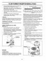
TO CHANGE ENGINE OIL (See Fig.. 18 and 19)
CHECK
Determine temperature range expected before oil change_
All oil must meet API service classification SG
TRANSAXLE
OIL LEVEL
(See Fig. 17)
°
Be sure tractor is on level surface,
•
Block up rear axle securely or use a tractor jack
=
Remove left rear wheel by removing hub bolts.
o
o
Oil will drain more freely when warm.
Catch oil in a suitable container
,,
Remove oil fiII cap/dipstick. Be careful not to allow dirt
to enter the engine when changing oil
=
Remove filler plug from transaxle, Oil level must be
even with plug threads, if necessary, fill with SAE 30
motor oil, API-SG,, Replace filler plug,,
Reassemble wheel to hub°
o
Remove drain plug,
=
After oil has drained completely, replace oil drain plug
and tighten securely°
•
Refill engine with oil through oil fill dipstick tube, Pour
slowly+ Do not overfiIL For approximate capacity see
"PRODUCT SPECIFICATIONS"
on page 3 of this
manual,,
o
For approximate capacity see "PRODUCT
CATIONS" on page 3 of this manual,
SPECIFI-
TRANSAXLE
FILLER PLUG
0
O
Use gauge on oil fill cap/dipstick for checking level. Be
sure dipstick is in all the way for accurate reading°
Keep oil at "FULL" line on dipstick.,
O
OIL DRAIN PLUG
ENGINE OIL
FILLER CAPIDIPSTICK
FIG, 17
ENGINE
LUBRICATION
Only use high quality detergent oil rated with APt service
classification SG. Select the oil's SAE viscosity grade
according to your expected operating temperature,
FIG. 19
17
CUSTOM
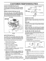
CLEAN
AIR SCREEN
RESIPO
ILmTUlE$
(See Fig. 20)
Air screen must be kept free of dirt and chaff to prevent
engine damage from overheating_ Clean with a wire brush
or compressed air to remove dirt and stubborn dried gum
fibers
FOAM
ENGINE
COOLING
FINS (See Fig. 20)
PRE_CLEANER,...,__...._._
Remove any dust, dirt or oil from engine cooling fins to
prevent engine damage from overheating. Engine blower
housing must be removed. Remove side panels and hood
(See"TO REMOVE HOOD AND GRILL ASSEMBLY" in the
Service and Adjustments section of this manuaL)
_.__
G
CARTRIDGE
FIG. 21
AIR SCREEN
ENGINE
COOLING FINS
(BOTH SIDES)
OIL FILTER
Replace the engine oil fitter every season or every other oil
change if the tractor is used more than 100 hours in one
year.
_i_.
MUFFLER
Inspect and replace corroded muffler and spark arrester (if
equipped) as it could create a fire hazard and/or damage.
SPARK
Replace spark plugs at the beginning of each mowing
season or after every 100 hours of operation, whichever
occurs first. Spark plug type and gap setting are shown in
"PRODUCT SPECIFICATIONS" on page 3 of this manual.
\
IN-LINE
(See Fig. 21)
Your engine witl not run properly using a dirty air filter.
Clean the foam pre-cleaner after every 25 hours of operation or every season. Service paper cartridge every 100
hours of operation or every season, whicheve r occurs first.
Service air cleaner more often under dusty conditions.
=
Remove wing nut and cover.
o
Remove seal and cartridge plate.
FUEL FILTER
(See Fig. 22)
The fuel filter should be replaced once each season, if fuel
filter becomes ctogged, obstructing fuel flow to carburetor,
replacement is required.
FIG. 20
AIR FILTER
PLUGS
.
With engine cool, remove filter and plug fuel line
sections.
-
Place new fuel filter in position in fuel line with arrow
pointing towards carburetor;"
•
Be sure there are no fuel line leaks and clamps are
properly positioned.
°
Immediately wipe up any spilled gasoline.
CLAMP
TO SERVICE PRE_CLEANER
.
Slide foam pre-cleaner off cartridge_
o
Wash it in liquid detergent and water.
-
Squeeze it dry in a clean cloth
.
Saturate it in engine oil. Wrap it in clean, absorbent
cloth and squeeze to remove excess oil.
CLAMP
- FUEL FILTER
FIG. 22
TO SERVICE CARTRIDGE
CLEANING
=
•
Clean engine, battery, seat, finish, etc, of all foreign
matter°
.
Keep finished surfaces and wheels free of all gasoline,
oil, etc.
.
Protect painted surfaces with automotive type wax.
Gently tap the fiat side of the paper cartridge to dislodge dirt. Do not wash the paper cartridge or use
pressurized air, as this wilt damage the cartridge.
Replace a dirty, bent, or damaged cartridge,
*
Reinstall the pre-cleaner
paper cartridge_
(cleaned and oiled) over the
=
Reassemble air cleaner, cartridge plate, and seal.
.
install the air cleaner cover and wing nut° Tighten wing
nut 1/2 turn to 1 full turn after nut contacts cover_ Do not
overtighten.
18
We do not recornmend using a garden hose to clean your
tractor unless the electrical system, muffler, air filter and
carburetor are covered to keep water ouL Water in engine
can result in a shortened engine life.
w,
i',
,,,,, ............
,
,
,
I,,H ,,,
,,,,,,,,, ,,
ir,lr,,,
,H,,, ¸
,
,
SERVDCE AND ADJUSTMENTS
, r , ,,',
,,,H,,,,
,
,,
,
,,,
i,mrvN,,ir
....
,H,,
_,HHr'H
CAUTION: BEFORE PERFORMING ANY SERVICE OR ADJUSTMENTS:
•
Depress clutch/brake
pedal fully and set parking brake.
•
-o
o
o
iii1,,,111, i
Place attachment clutch in "DISENGAGED"
position.
Place ignition
gearshift keylever
in neutral
(N) position.
Turn
"OFF"
and remove
key.
Make sure the blades and all moving parts have completely stopped°
Disconnectsparkplugwirefromsparkplugandplacewirewhereitcannotcomeincontactwith
p,ug.
,i
TO REMOVE
i........................
MOWER
TO LEVEL MOWER
(See Fig. 23)
o
Place attachment c_Jtch in "DISENGAGED"
.
Turn height adjustment knob to lowest setting.
position_
°
Lower mower to its lowest position,
•
Remove retainer spring holding anti-swaybar to chassis bracket and disengage anti-swaybar from bracket
•
Remove retainer springs from suspension
deck and disengage arms from deck.
o
Raise attachment Iift to its highest position.
.
Remove two retainer springs from each front link and
remove IJnkso
•
Slide mower forward and remove be_t from electric
clutch pulley,
Adjust the mower while tractor is parked on _evelground or
driveway,
Make sure tires are properly inflated (See
"PRODUCT SPECIFICATIONS"on
page 3 of this manual).
If tires are over or underinflated, you will not properly adjust
your mower,
SIDE-TO-SIDE ADJUSTMENT (See Figs. 23 and 24)
•
Raise mower to its highest position°
arms at
•
Slide mower out from under right side of tractor
IMPORTANT: IF AN ATTACHMENT OTHER THAN THE
MOWER DECKIS TO BE MOUNTED ON THE TRACTOR,
RE,MOVE THE FRONT LINKS
TO INSTALL
HOUSING
•
Measure height from bottom of deck curl to ground
level at front corners of mower_ Distance "A" should be
the same°
o
If distance "A" needs to be changed, make adjustment
on one side of mower only_
°
Raise one side of mower by tightening lift link adjustment nut on that side.
o
Lower one side of mower by loosening lift link adjustment nut on that side.
NOTE: Each half turn of adjustment nut wilt change deck
level about 1/4".
MOWER
o
Follow procedure described in "INSTALL MOWER AND
DRIVE BELT" in the Assembiy section of this manual,
Recheck level after adiusting.
BOTTOM
ADJUSTMENT
NUTS
LIFT
LINKS
SUSPENSION
ARMS
OF C_
FRONT
SUSPENSION
BRACKET_
RONo OWER
\
CHASSIS
BRACKET
FIG, 24
ELECTRIC
CLUTCH
PULLEY
FRONT
SUSPENSION
BRACKET
RETAINER
RETAINER
SPRING
FRONT MOWER
BRACKET
ANTI,,SWAY
BAR
RETAINER
SPRINGS
FIG. 23
!9
..................................................................
SERVICE AN
i
,,
IH''N'IIII
...................... I1'
i
......................
ADJUSTMENTS
r
I'
'
I
I
I
TO REPLACE
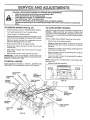
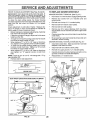
FRONT-TO-BACK ADJUSTMENT (See Figs. 25 and 26) IMPORTANT: DECK MUST BE LEVEL SIDE-TO-SIDE, IF
THE FOLLOWING FRONT-TO-BACK ADJUSTMENT tS
NECESSARY, BE SURE TO ADJUST BOTH FRONT LINKS
EQUALLY SO MOWER WILL STAY LEVEL SIDE-TO*SIDE.
MOWER
DRIVE
I
'1
I
BELT
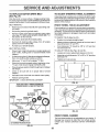
MOWER DRIVE BELT REMOVAL (See Fig_ 27) o
Park tractor' on a level surface. Engage parking brake°
Remove four screws from L,H. mandrel cover and
remove cove ro
o
Roll belt over the top of L,H_ mandrel pulley,
-
Remove belt from electric clutch pulley.
Check adjustment on right side of tractor. Measure distance "F" directly in front of and behind the mandrel at
bottom edge of mower housing as shown.
o Before making any necessary adjustments, checkthat
both front links are equal in length_
o
If links are not equal in length, adjust one link to same
length as other' link
°
To lower front of mower housing, loosen nut"G" on both
front links an equal number' of turns
°
When distance "F" is 1/8" to 1/2" lower at front than
rear, tighten nut"H" against trunnion on both front links,
To raise front of mower housing, loosen nut"H" from
trunnion on both front links. Tighten nut "G" on both
front links an equal number of turns,
o When distance "F" is 1/8" to 1/2" lower at front than
rear', tighten nut "H" against trunnion on both front
links
o
Remove belt from idler pulleys_
°
Remove any dirt or grass ctppings which may have
accumulated around mandrels and entire upper deck
surfacer
°
Check primary idler arm and two idlers to see that they
rotate freely.
°
Be sure spring is securely hooked to primary idler arm
and bolt in mower housing.,
NOTE: Each ful! turn of nut "G" will change dim. "F" by
approximately 3/8%
Recheck side-to-side adjustment.
=
e
To obtain the best cutting results, the mower housing
should be adjusted so the front is approximately 1/8" to 1/2"
lower than the rear when the mower is in its highest
position
MOWER DRIVE BELT INSTALLATIOt_ (See Fig. 27) °
Install belt in both idlers, Make sure belt is in both belt
keepers at the idlers as shown,
=
Install new belt onto electric clutch pulley.
=
Roll belt into upper groove of LH. mandrel pulley.
°
Carefully check belt routing making sure belt is in the
grooves correctly and inside belt keepers.
Reassemble LH mandrelcover.
L.H.
MANDREL
COVER
SPRING
IDLER
PULLEYS
'_
,,p,,f
i
ELECTRIC
CLUTCH
PULLEY
PRIMARY
IDLER
ARM
f,,=,,
GROUND
2!77777727/17<ttiltlt71ttifi7tlli')tl1!11_
LINE
I "
FIG. 25
BOLT IN
MOWER
HOUSING
BOTH FRONT LINKS SHOULD BE EQUAL IN LENGTH
MANDREL
MOWER
DRIVE BELT
NUT "G"
FIG, 27
NUT "H
FRONT LINKS
FIG= 26
20
SERVICE AND ADJUSTMENTS
lunl
TO REPLACE
(See Fig. 28)
MOWER
BLADE
DRIVE
BELT
Park the tractor on level surface. Engage parking brake,
Remove mowerdrive belt (See'_FO REPLACE MOWER
DRIVE BELT" in this section of this manual).
o
Remove mower (See "TO REMOVE MOWER" in this
section of this manual)
•
Remove four screws from Roll mandrel cover and
remove cover° Unhook spring from bolt on mower
housing°
.
Carefully roll belt off Roll. mandrel pulley.,
Remove belt from center mandrel pulley, idler pulley,
and LH, mandrel pulley
.
Remove any dirt or grass which may have accumulated around mandrels and entire upper deck surface.
•
Check secondary idler arm and idler to see that they
rotate freely,
.
Be sure spring is hooked in secondary idler arm and
sway-bar bracket°
=
Install new belt in lower groove of LH, mandrel puiley,
idler pulley, and center mandrel pulley as shown.
Roll belt over R,,H.,mandrel pulley. Make sure belt is in
all grooves propefly_
.
Reconnect spring to bolt in mower housing and reinstall R.Ho mandrel cover.
.
Reinstall mower to tractor (See "iNSTALL MOWER
AND DRIVE BELT' in the Assembly section of this
manual)o
@
Reassemble mower drive belt (See "TO REPLACE
MOWER DRIVE BELT" in this section of this manual).
L.H.
MOWER BLADE
DRIVE
CENTER
MANDREL
MANDREL
COVER
SECONDARY
IDLER ARM
SPRING
SWAY-BAR
BRACKET
IDLER
PULLEY
FIG. 28
TO ADJUST ATTACHMENT
(See Fig, 29)
CLUTCH
The electric clutch should provide years of service° The
clutch has a built-in brake that stops the pulley within 5
seconds,, Eventually, the internal brake will wear which
may cause the mower blades to not engage, or, to not stop
as required. Adjustments should be made by your nearest
authorized service center/department.
.
Make sure attachment clutch and ignition switches are
in "OFF" position.
o Adjust the three nylon Iocknuts until space between
clutch plate and rotor measures .012" at all three slot
locations cut inside of brake plate_
NOTE: After installing a new electric clutch, run tractor at
full throttle and engage and disengage electric c_utch 10
cycles to wear in clutch plate
21
iiiiii
ROTOR\
CLUTCH
SLOT (3_ '-'--' -_
PLATE
_
'--"
NYLON LOCKNLIT {3)
BRAKE PLATE
FIG. 29
TO ADJUST
BRAKE
(See Fig. 30)
Your tractor is equipped with an adjustable brake system
which is mounted on the left side of the transaxle.
If tractor requires more than six (6) feet stopping distance
at high speed in highest gear, then b rake must be adjusted°
IMPORTANT: DO NOT OVER TIGHTEN BRAKE. WHEN
DEPRESSING CLUTCH BRAKE PEDAL, THE MOTION
DRIVE BELT MUST STOP MOVING (DECLUTCH FROM
ENGINE
PULLEY)
BEFORE
BRAKE ENGAGES.
IMPROPER ADJUSTMENT WILL CAUSE HARD SHIFTING
AND EXCESSIVE WEAR TO BRAKE LINING,
•
Park and turn off the tractor on a level surface, Place
gear shift lever in neutral (N) position., Disengage
parking brake and be sure tractor does not rotl in either
direction_
o Lower mower deck (if installed on tractor)
.
Snap out access hole cover on te{t side o{ tractor above
footrest,
o Loosen jam nut at clevis which wilt allow brake rod to be
rotated,,
•
With pliers, from underside of frame, unscrew brake
rod from clevis four (4) to six (6) full turns,
•
Start tractorwith gear shift lever in neutra_ (N) position.
•
Slowly depress clutch/brake pedal to the point where
the motion drive belt stops moving., Hold clutch/brake
peda_ in this position and engage parking brake. !{belt
begins to move after engaging parking brake, reset
parking brake by depressing clutch/brake pedal slightfy
to next notch on parking brake.
°
Stop engine. Screw brake rod back into clevis until
clevis pin is against rear edge of slot in brake arm, Do
not over tighten (see "IMPORTANT' above)
•
Tighten jam nut against clevis_
.
Replace access hole cover,
•
Road test tractor for proper stopping distance and
declutching as stated above Readjust if necessary. If
proper adjustment cannot be attained, further maintenance is necessary° Contact your nearest authorized
se rvice center/department.
CLEVt s
_ JAM N\UT
__._._
_
PIN
BR.,. E I
ARM
/
\
LOJ' J
BR_,KE_)
_LE__C_LE.Y.L_
ROD
--
_
FIG. 30
(_
___7
=, Hi
,
i, i,, ,,=
$
CE AN
....................
TO REPLACE
MOTION
ADJUSTMENTS
ii
DRIVE
BELT
TO ADJUST
(See Fig. 31)
STEERING
WHEEL
ALIGNMENT
Park the tractor on level surface. Engage parking brake.
For ease of service there is a belt installation guide decal on
bottom of Ieft footresto It isnot necessaryto rernove mower.
If steering wheel crossbars are not horizontal (left to right)
when wheels are positioned straightforward, remove steering wheel and reassemble per instructions in the Assembly
section of this manual
BELT REMOVAL
FRONT
=
Raise hood and disconnect BLACK (grounding) battery cable,,
•
Set parking brake (to get belt slack).
=
Remove mower drive belt from electric clutch pulley
only (See "TO REPLACE MOWER DRIVE BELT" in
this section of this manual).
Front wheel toe-in is required for proper steering operation,_
Toe-in was set at the factory and adjustment should not be
necessary. If parts in the front axle or steering mechanism
have been replaced or damaged, check toe-in and adjust
if necessary
°
Roll motion drive belt off transaxle pulley,
=
Roll belt off clutching idler pulleys, then off engine
pulley and front V-idler pulley,
-
Pull belt out of all belt keepers.
BELT INSTALLATION
=
•
-
Place V part of belt into grooves on engine pulley and
front V-idler, making sure to route belt inside of belt
keepers.
o
Put belt coming from V-idter above midspan belt keeper,
then onto clutching idler pulleys as shown.
o
Make sure "V" part of belt engages"V"
•
Place belt around transaxle pulley, beginning at top.
"V" part of belt should engage transaxle pulley.
•
Place long lower section of belt through loop in midspan
belt keeper,,
-
Check to be sure belt is on proper side of all belt
keepers.
o
Reinstall mower drive belt onto electric clutch pulley.
ADJUSTMENT
TO CHECK TOE-IN (See Fig,, 32) -
.
•
WHEEL TOE-IN
Position front wheels straight ahead.
Measure distance between wheels at front and rear of
tires (dimensions "A" and "B"),
Front dimension "A" should be 1/_" to 1/4" less than
rear dimension "B"v
TO ADJUST TOE-IN (See Figs,,32 and 33) *
.
Loosen jam nuts at adjustment sleeves on tie rod.
idler.
•
Adjusttieroduntildimension"A"isl/8"tol/4"lessthan
dimension "B".
,
Tighten jam nuts securely,
FRONT
OF TRACTOR
= Release parking brake.
IMPORTANT: CHECK BRAKE ADJUSTMENT.
FIG. 32
TRACTOR V-BELT DRIVE SCHEMATIC
VIEWED FROM L,H. SIDE OF TRACTOR
CLUTCHING
IDLER
ADJUSTMENT
SLEEVES
BELT
CLUTCHING
FLAT IDLER
ENGINE
PULLEY
V-IDLER
JAM NUTS
KEEPER
BELT
TWISTS
BELT
KEEPER
ENGINE
PULLEY
TRANSAXLE
PULLEY
FIG. 33
FRONT
ASVIEWED
FROM
WHEEL
CAMBER
The front wheel camber is not adjustable on your tractor. If
damage has occurred to affect the front wheel carnber,
contact your nearest authorized service center/department.
BOTTOM
FIG. 31
22
ii1,, i
iiii i ,,11
ii
iii
$ERVHCE AND ADJUSTMENTS
i
,,111
i1,11111,1,,
TO REMOVE
,i i
WHEEL
ii, i ii
iii
i1,,i,,11
FOR REPAIRS
FRONT WHEEL (See Fig. 34) °
BIockup axle securely_
•
Remove axle cover, retaining ring and washers to allow
wheel removal
•
Repair tire and reassemble.
•
Replace washers and snap retaining ring securely in
axle groove.
•
Replace axle cover.
"POSITIVE"(+)
"NEGATIVE"(-)
o
PANEL
WASHERS
RETAINING
RIN(
AXLE
COVER
\
FIG. 35
TO REPLACE
FIG. 34
°
Pull bulb holder out of the hole in the backside of the
grill°
•
Replace bulb in holder and push bulb holder securely
back into the hole in the backside of the grill
CIosehood.
•
Block rear axle securely..
.
Remove five (5) hub bolts to allow wheel removal..
°
°
Repair tire and reassemble.
bolts securely_
INTERLOCKS
TO START ENGINE
'See Fig. 35)
o
i1,11,1,111
i,ii
CAUTION: [.ead-acid batteries generate explosive gases. Keep sparks, flame
and smoking materials away from batteries.
Always wear eye protection
when around batteries.
IMPORTANT:
YOUR UNIT IS EQUIPPED WITH A 12
VOLT NEGATIVE GROUNDED SYSTEM THE OTHER
VEHICLE MUST ALSO BE A 12 VOLT NEGATIVE
GROUNDED SYSTEM. DO NOT USE YOUR TRACTOR
BATTERY TO START OTHER VEHICLES
TO ATTACH JUMPER CABLES -
=
Connect one end of the BLACK cable to the NEGATIVE (_) terminal of fuliy charged battery.
°
Connect the other end of the BLACK cable to good
CHASSIS GROUND, away from fuel tank and battery.
TO REMOVE CABLES, REVERSE ORDER =
BLACK cable first from chassis and then from the fully
charged battery.
•
RED cable last from both batteries
FUSE
Replace with 30 amp automotive-type plug-in fuse
fuse holder is located behind the dash.
If your battery is too weak to start the engine, it should be
recharged.. If "jumper cables" are used for emergency
starting, follow this procedure:
Connect each end of the RED cable to the POSITIVE
(+) terminal of each battery, taking care not to short
against chassis.
Check wiring. See electrical wiring diagram in the
Repair Parts section of this manual..
TO REPLACE
i,iiiiiii, iii
°
AND RELAYS
Loose or damaged wiring may cause your tractor to run
poorly, stop running, or prevent it from starting.
WITH A WEAK BATTERY
i
BULB
Raise hood.
REAR WHEEL
Replace and tighten hub
HEADLIGHT
°
23
The
TO ADJUST ATTACHMENT
(See Fig. 36)
LIFT SPRING
,,
While holding spring bushing with wrench, loosen jam
nut.
,,
Turn adjustment bolt clockwise to extend spring and
reduce lift effort for heavier attachments.
o
Turn adjustment bolt counterclockwise
tachments.
ADJUSTMENT
SPRING
for lighter ato
JAM NUT
Retighten jam nut against spring bushing.
IMPORTANT: DO NOTADJUST FOR MAXIMUM SPRING
TENSION WHEN USING LIGHT ATTACHMENTS SUCH
ASA MOWER. ADJUST LIFT LEVER SPRING TO AID IN
LIFTING ATTACHMENT DO NOT OVERPOWER SPRING.
WHEN REMOVING ATTACHMENT, ALWAYS ADJUST
SPRING TENSION TO ITS LOWEST POSITION
TO REMOVE
HOOD
BUSHING
°_
ATTACHMENT
LIFT SPRING
o
FIG. 36
AND GRILL ASSEMBLY
(See Fig. 37)
o
Raise hood.
°
Unsnap headlight wire connector°
HOOD
WIRE
CONNECTION
\
Stand in front of tractor. Grasp hood at sides, tilt toward
engine and lift off of tractor.
=
To replace, reverse above procedures.
FIG. 37
24
,..i .....
i
.IL.I. i
_mlll.........i
........
i1..i...i, i
ii
SERVICE AN
......................................
i
.
..r....11.1
i
Jl
_
i
iiiii i
ii ii
CONTROL
,,
CABLE
The throttle control has been preset at the factory and
adjustment should notbe necessary, Checkadjustment as
described below before loosening cable. If adjustment is
necessary, proceed as foilows:
°
With engine not running, move throttle control leverto
fast 0 position°
°
Check that speed control Iever is against stop screw. If
it is not, loosen casing clamp screw and pull throttle
cable until lever is against screw_ Tighten clamp screw
securely.
.............
,.i......i.i
m_lll..i..
..................
CARBURETOR
(See
Move throttle control lever from slow 0 to fast 0
position. If engine hesitates or dies, turn idle mixture
screw out (counterclockwise)
t/8 turn. Repeattestand
continue to adjust, if necessary,
until engine accelerates smoothly.
High speed stop is factory adjusted,
may result.
Do not adjust-damage
IMPORTANT;
NEVER
TAMPER
WITH THE ENGINE
GOVERNOR,
WHICH IS FACTORY
SET FOR PROPER
ENGINE SPEED_ OVERSPEEDING
THE ENGINE ABOVE
THE
FACTORY
HIGH
SPEED
SETTING
CAN BE
DANGEROUS.
IF YOU THINK THE ENGINE-GOVERNED
HIGH SPEED NEEDS ADJUSTING,
CONTACT
YOUR
NEAREST
AUTHORIZED
SERVICE
CENTER/
DEPARTMENT,
WHICH HAS PROPER EQUIPMENTAND
EXPERIENCE
TO
MAKE
ANY
NECESSARY
ADJUSTMENTS.
Fig. 40)
The carburetor has been present at the factory and adjustmerit should not be necessary. However, minor adjustment
may be required to compensate for differences in fuel,
temperature, altitude or load. If the carburetor does not
need adjustment, proceed as follows:
CASING
CLAMP
In general, turning the adjusting needles in (clockwise)
decreases the supply of fuel to the engine giving a leaner
fuel/air mixture_ Turning the adjusting needles out (counterclockwise) increases the supply of fuel to the engine
giving a richer fueVair mixture.
IMPORTANT:
DAMAGE TO THE NEEDLES AND THE
SEATS IN CARBURETOR MAY RESULT IF SCREW IS
TURNED _NTOO TIGHT_
STOP SCREW
SPEED CONTROL
LEVER
THROTTLE
CONTROL
CABLE
SETTING -
=
Be sure you have a clean air filter, and the throttle
control cabie is adjusted properly (see above).
o
With engine off turn idle fuel adjusting needle in (cfockwise) c[ostng it finger tight and then turn out (counterclockwise) 1-1/4 turns°
-
Turn main fuel adjusting needle in (clockwise) closing
linger tight and then turn out (counte rclockwise) 1 turn.
FIG. 38
STOP
SCREW
SPEED
CONTROL
LEVER
FINAL SETTING =
Start engine and allow to warm for five minutes., Make
final adjustments with engine running and shift/motion
control lever in neutral (N) position.
=
With throttle control lever in fast 0 position, turn main
fuel adjusting needle in (clockwise) until engine begins
to die then turn out (cotJnterclockwise) until engine
runs rough. Turn needle to a point midway between
those two positions.
,,
-
ACCELERATION
TEST-
TO ADJUST THROTTLE
(See Fig. 38 & 39)
PRELIMINARY
.................
ADJUSTMENTS
E N GIN E
TO ADJUST
ii i.i
FIG. 39
!dle speed setting - With throttle control lever in slow 0
position, engine should idle at 1400 RPM If engine
idies too slow or fast, turn idle speed adjusting screw in
or out until correct idle is attained
IDLE FUEL
ADJUSTING
EEDLE
o
!die fuel needle setting - With throttle contro_ lever in
slow () position, turn idle fuel adjusting needle in
(clockwise) unti_ engine begins to die and then turn out
(counterclockwise) until engine runs rough. Turn needle
to a point midway between those two positions..
=
Recheck idle speed. Readiust if necessary
25
FIG. 40
.....................
i
,
i,,
=, 'mH"H"
STORAGE
l
,
1, Hm
,11,,,,1,1
ENGINE
Immediately prepare your tiactor for storage at the end of
the season or if the tractor will not be used for 30 days or
lore,
.................
1..1 = 1.1.1,.
11
FUEL SYSTEM
.mi=_
IMPORTANT:
iT IS iMPORTANT TO PREVENT GUM
DEPOSITS FROM FORMING IN ESSENTIAL FUEL
SYSTEM PARTS SUCH AS CARBURETOR, FUEL FILTER,
FUEL HOSE, OR TANK DURING STORAGE.
ALSO,
EXPERIENCE INDICATES THAT ALCOHOL BLENDED
FUELS (CALLED GASOHOL OR USING ETHANOL OR
METHANOL) CAN ATTRACT MOISTURE WHICH LEADS
TO SEPARATION AND FORMATION OF ACIDS DURING
STORAGE,
ACIDIC GAS CAN DAMAGE THE FUEL
SYSTEM OF AN ENGINE WHILE [N STORAGE.
I
CAUTION: Never store the tractor with
gasoline in the tank inside a building
i
where fumes may reach an open flame
I
or spark.
Allow the engine to cool
before storing in any enclosure.
.................
11
=mi=
11m=..==
.1.1.
TRACTOR
Remove mower from tractor for winter storage_ When
mower is to be stored for a period of time, clean it thor =
oughly, remove alt dirt, grease, leaves, etc. Store in a
clean, dry area.
o
Clean entire tractor (See"CLEANfNG" in the Customer
Responsibilities section of this manual).
•
Inspect and replace belts, if necessary (See belt replacement instructions in the Service and Adjustments
section of this manual),
Lubricate as shown in the Customer Responsibilities
section of this manual
=
o
Be sure that all nuts, bolts and screws are securely
fastened. Inspect moving parts for damage, breakage
and wear Replace if necessary,.
.
Touch up all rusted or chipped paint surfaces; sand
lightly before painting.
Fully charge the battery for storage°
•
After a period of time in storage, battery may require
recharging
.
•
Drain the fuel tank.
o
Start the engine and let it run until the fuel lines and
carburetor are empty_
o
Never use engine or carburetor cleaner products in the
fuel tank or permanent damage may occur.
Use fresh fuel next season.
.
NOTE: Fuel stabilizer is an acceptable alternative in
minimizing the formation of fuel gum deposits during storager Add stabilizer to gasoline in fuel tank or storage
container, Always follow the mix ratio found on stabilizer
container', Run engine at least 10 minutes after adding
stabilizer to allow the stabilizer to reach the carburetor. Do
not drain the gas tan k and carburetor if using fuel stabilizer.
ENGINE
OIL
Drain oil (with engine warm) and replace with clean engine
oilo (See "ENGINE" in the Customer Responsibilities
section of this manual).
BATTERY
o
*
CYLINDERS
To help prevent corrosion and power leakage during
long periods of storage, battery cables should be
disconnected and battery cleaned tho roughly (see"TO
CLEAN BATTERY AND TERMINALS" in the Customer Responsibilities section of this rnanual)o
o
Remove spark plug(s),
•
Pour one ounce of oil through spark plug hole(s) into
cylinder(s).
Turn ignition keyto"START"
to distribute oil,
°
After cleaning leave cables disconnected and place
cables where they cannot come in contact w th battery
terminals.
position for a few seconds
Replace with new spark plug(s).
OTHER
°
Be sure battery drain tube is securely attached.
.
Do not store gasoline from one season to another_
.
If battery is removed from tractor for storage, do not
store battery directly on concrete or damp surfaces.
o
Replace your gasoline can if your can starts to rust.
Rust and/or dirt in your gasoline will cause problems.
°
If possible, stole your tractor indoors and cover it to
give protection from dust and dirt.
•
Cover' your tractor with a suitable protective covet'that
does not retain moisture. Do not use plastic. Plastic
cannot breathe which allows condensation to form and
win cause your tractor to rust.
IMPORTANT: NEVER COVERTRACTOR WHILE ENGINE
AND EXHAUST AREAS ARE STILL WARM.
26
SERVICE NOTES
27
TROUBLESHOOTING
IPOJNT$
i1,1,1,1,11111111,
,,11
PROBLEM
Wilt not start
CAUSE
i
iiii
CORRECTION
1
Out of fuel
2
3
4
5
6.
7.
Engfne not "CHOKED"
Engine flooded
Bad spark plug
Dirty air filter
Didy fuel fitter
Water in fuel.
8,
Loose or damaged wiring.
Carburetor out of adjustment.
Engine valves out of adjuslmenL
9
10
iii
propedy
1
Fill fuel tank
2.
3.
4
5.
6
7
See "TO START ENGINE" in Operation section
Wait several minutes before attempting to start.
Reptace spark plug.
Clean!replace air fitter
Replace fuel filter
Drain fuel tank and carburetor, refill tank with fresh
gasoline and replace fuel filter
Check all wiring
Contact an authorized service center/department.
Contact an authorized service center/department.
8
9
10.
ii .....................
Hard to start
t
2
3
4.
5
Dirty air filter
Bad sparkptug
Weak or dead battery
Dirty fuel filter
Stale or dirty fuet
6.
7,.
8
Loose or damaged wiring
Carburetor out of adjustment
Engine valves out of adjustment
1
2.
3.
4
Clutch/brake pedat not depressed,
Attachment clutch is engaged,
Weak or dead battery.
Blown fuse
5.
6
7
8
9
Engine clicks but will not
start
Loss of power
Engine will not turn over
1
2
3
4_
5
6
7
8.
Cteardreplace air filter,
Replace spark plug
Recharge or replace battery
Replace fuel filter.
"it'
Drain fuel tank and refill with fresh gasoline
Check all wiring
Contact an authorized service center/department
Contact an authorized service center/department.
Corroded battery terminals
Loose or damaged widng
Faulty ignilion switch
Faulty solenoid or starter
Faulty operator presence switch(es)
1
2
3
4
5
6
7
8
9.
Depress clutch!brake pedal
Disengage attachment clutch
Recharge or replace battery
Replace fuse
Clean battery terminals
Check eli wiring
Check/replace ignifion switch
Check/replace solenoid or slarter.
Conlact an authorized service centeddepartment
1
2
3
4
Weak or dead battery,,
Corroded battery terminals
Loose or damaged wiring
Faulty solenoid or starter.
1
2.
3,
4,,
Recharge or replace battery
Clean battery terminals.
Check all wiring
Check/replace solenoid or starter.
t
2
3
4
5
6.
7,
8.
9.
Cutting too much grass/too fast,
Throttle tn "CHOKE" position.
Build-up of grass, leaves and trash under mower
Dirty air filter,
Low oil tevelldJrty oil.
Faulty spark plug
Dirty fuel filter,
Stale or dirty fuel,
Water in fuel
1
2
3_
4_
5.
6.
7_
8_
9.
Set in "Higher Cut" posttlon/reduce speed.
Adjust throttle controi
Clean underside of mower housing.
Clean/replace air filter
Check oil leveVchange oil
Clean and regap or change spark plug
Replace fuel filter
Drain fuel tank and refill with fresh gasoline.
Drain fuel tank and carburetor, refill tank with fresh
gasoline and replace fuel filter.
Conhect and ttghlen spark plug wire
Clean engine air screen/fins
Clean/replace muffisL
Check all wiring,
Contact an authorized service center/department.
Contact an authorized sewlce center/department.
10
11
12
13
14
15
Excessive
vibration
1
2
3
Spark plug wireloose
Dirty engine atr sereedlins
Didy/clogged muffler
Loose or damaged wiring
Carburetor out of adjustment
Engine valves out of adjustment
10
11
12.
13
14
15.
Worn, bent or loose btade
Bent blade mandrel.
Loose/damaged pert(s)
1
2
3
28
Replace blade Tighten biade bolt.
Replace blade mandrel
Tighten loose part(s) Replace damaged parts,
..
' '
,,
,,,,,i,i
........
i,,,i,,_,,,,,,ii
TROUBLESHOOTmNG
.....
PROBLEM
i,,, ,,,,i .....
,.......
, ,,,
i
........ i,,i,i, ,
POINTS
_
..............................
CAUSE
CORRECTION
................
Engine continues to run
when operator leaves seat
with attachment clutch
1
Faulty operator-safety
presence
control system
,,,,,
,
,
,
Check wiring, switches and connections
tf not
corrected, contact an authorized service center/
depadmen!
engaged
Poor cut-
uneven
Mower blades wif! not
rotate
1
2
Worn, bent or loose blade
Mower deck not level
1
2
Replace blade Tighten blade bolt
Level mower deck
3
4
5
Buildup of grass, leaves, and trash under mower
Bent blade mandrel
Clogged mower deck vent holes from buildup of
grass, leaves, and trash around mandrels
3
4
5
Clean underside of mower housing
Replace blade mandrel
Clean around mandrels to open vent hoies
1.
Obstruction
2
3,
4
Wornldamaged mower drive belt
Frozen idler pulley
Frozen blade mandrel,
1
2
3
4
Remove
Replace
Replace
Replace
in clutch mechanism
obstruction.,
mower drive belt
idler pulley
blade mandre{
....i,,,11111,,
,,,,,i,1,11,,,,i
,,,,i,,,11,i
Poor grass discharge
1.
2.
3
4
5
6
Engine speed too slow
Travel speed too fast
Wet grass
Mower deck not level
Low/uneven tire air pressure
Worn, bent or loose blade
7
8
Buildup of grass, leaves and trash under mower
Mower drive belt worn
, 9
10
t1
!
2
3,
4
Blades improperly installed
Improper blades used
Clogged mower deck vent holes from buildup of
grass, leaves, and trash around mandrels
5
6
7
8
9
!0
tl
,
Place lhrotHe control tn "FAST" position
Sl_ift to siower speed
Allow grass to dry before mowing
Level mower deck
Check tires for proper air pressure,
Replace/sharpen blade Tighten blade bolt
Clean underside of mower housing
Replace mower drive belt
Reinstall blades sharp edge down
Replace with blades listed tn this manual
Clean around mandrels to open vent holes
Headlight(s) not worklng
(if so equipped)
t,,
Switch is "OFF"
!
Turn switch "ON"
2
3
4
5
Bulb(s) burned out
Faulty light switch
Loose or damaged wiring
Blown fuse
2
3
4
5
Replace bulb(s)
Check/replace light switch
Check wiring and connections
Replace fuse
Battery
I
2
Bad battery celi(s)
Poor cable connections
1
2.
Replace battery
Check/clean all connections
3
4
Faulty regulator (if so equipped)
Faulty alternator
3
4
Replace regulator
Replace alternator
1
Engine throttle control not set at "SLOW"
position for 30 seconds before stopping engine,,
1
Move throttle controi to "SLOW" position and allow
will not charge
Engine "backfires"
when turning engine
"OFF"
29
to idle for 30 seconds before stopping engine
30