1
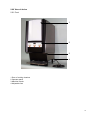
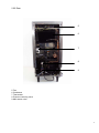
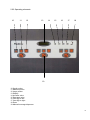
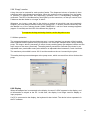
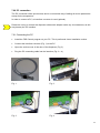
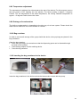
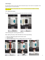
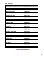
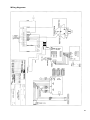
Beverage Dispensing Technology
Friedhelm Selbach GmbH
Heisenbergstr. 5
42477 Radevormwald
Germany
Tel. +49/ (0) 21 95 / 68 01-0
Fax +49/ (0) 21 95 / 68 01-188
E-mail [email protected]
Internet: http://www.selbach.com
Operating Manual
60-0431-0000
28.09.07
Fruit Juice Dispenser
The device described in this manual may only be put into operation provided the operators are suitably
trained and the operating and maintenance personnel have studied the instructions closely.
Table of Contents
1.00
1.10
1.20
1.30
1.40
1.50
1.51
1.52
1.60
2.00
2.01
2.00
2.01
2.02
2.03
2.04
3.00
4.00
4.01
4.02
4.03
5.00
5.01
5.02
5.03
5.04
5.05
5.06
5.07
5.08
5.09
5.10
6.00
7.00
7.01
7.02
7.03
8.00
9.00
10.00
11.00
12.00
12.01
12.02
12.03
13.00
13.01
13.02
13.03
14.00
15.00
16.00
Safety instructions
Assembly/start-up
Safety instructions
Safety risks
Safety directives
Spare parts
Transportation/storage
Electrical connection
Water connection
Operation
Service
View of device
Front
Rear
Operating elements
Key switches
Status LED of controller main board
Controller software
Menu structure
Code number
Editing the menu options
Variable parameters
No. of pulses per 100 ml of syrup
No. of pulses per litre of water
Mixing ratio
Portion size
Manual limitation
Water pre- and post-feed
Language
Dispensing of product
“Empty“ monitor
Motor protection
Display
PC connection
Connecting the PC
Reading out parameters with the PC
Editing parameters with the PC
Temperature adjustment
Drainage of condensation
Bag container
Inserting bag containers in the device
Pumps
Opening the pump
Inserting and connecting the feed hose
Water flush
Maintenance
Opening the rear panels
Cleaning
Cleaning the condenser
Troubleshooting
Technical data
Spare part list
Wiring diagramm
Page
3
3
3
4
4
4
4
4
4
5
5
6
6
7
8
9
9
9
9
9
10
11
11
11
11
11
12
12
12
12
13
13
13
14
14
15
15
16
16
16
16
17
17
17
18
18
18
18
18
19
19
20
22
2
1.00 Safety instructions
1.10 Assembly/start-up
Place the device on an even, dry and clean surface. Make sure the connecting cable leads
directly to the socket, and that it cannot be bent or squashed.
Only use the original hoses for the water supply.
The device must be adequately ventilated at all times! Make sure no objects are placed on or
under the device!
The device can be assembled horizontally using the height-adjustable feet.
The following safety measures must be observed without fail:
Never exceed the input limits in the parameter list in either direction
Operating temperature range +10 to +40 degrees Celsius
Maximum assembly height 1000m above sea level
Do not allow dirt (dust, fibres, etc.) to get inside the device
Only connect to the prescribed supply voltage
If using in extreme electrical conditions, ensure adequate filtration of the mains voltage
Protect the assemblies from moisture, especially penetrating liquids
Observe the hazard warnings and safety instructions on the electrical components and in
this manual
Observe the generally applicable safety regulations when laying cables (minimum distances,
insulation, strain relief, etc.)
Observe the warnings and service instructions in this manual
1.20 Safety instructions
The device described in this manual may only be operated and connected by suitably trained
personnel. Adjustments, maintenance and repair work on the open or live device may only be
performed by a specialist.
As with all technical equipment, this device is only guaranteed to work properly and safely
provided the generally applicable safety precautions and the specific safety instructions in this
manual are observed during operation and service.
Serious damage to persons and property can be caused by:
Improper use
Incorrect installation or operation
Unauthorised removal of the necessary protective coverings or housing
Unauthorised opening of the device during operation
3
1.21 Safety risks
If a safety risk is considered to exist for any reason, the device must be taken out of operation
and suitably marked in order to prevent it from being started up again inadvertently by a third
party. The customer service department must also be notified accordingly.
Examples of safety risks include failure to operate in the prescribed manner or visible signs of
damage.
1.22 Safety directives
The device may only be operated with a properly connected PE conductor.
1.30 Spare parts
Assemblies or components may only be replaced with identical spare parts. Do not use different
sized fuses to those prescribed under any circumstances.
1.40 Transportation/storage
Any damage discovered after delivery must be reported immediately to the transport company.
If necessary, take suitable measures to prevent the device from being put into operation. The
device may only be stored in a dry, dust-free environment at a temperature between 0 and 60
degrees. After transporting the device to the site of installation, make sure it is not put into
operation for at least 24 hours in order to eliminate any condensation in the electrical
components.
1.50 Electrical connection
Electrical tasks may only be carried out once:
The electrical system has been disconnected from the voltage supply and prevented from
being switched on again accidentally
The absence of voltage has been checked
You have make sure that additional monitoring and protective devices for the control system
are correctly installed.
When connecting the wires, make sure that
The applicable standards and regulations are observed
A permanent electrical connection is guaranteed
1.51 Water connection
The device has a built-in, permanently adjusted water pressure reducing valve. The system
water pressure must not exceed a maximum of 7 bar or a minimum of 1.9 bar. If the water
pressure is higher, please contact the responsible service department. The water supply is
connected via an adapter with a 5/8“ thread on the underside of the device. The water
connecting nipple on the device is included in the scope of delivery.
4
1.52 Operation
Should the device deviate in any way from its normal operation, always take it out of operation if
in doubt and mark it suitably in order to prevent it from being started up again by a third party.
Also notify the customer service department.
1.60 Service
All service instructions contained in the manual(s) must be observed without fail.
Special attention should be paid to the safety instructions in the electrical
documentation supplied with the external devices.
5
2.00 View of device
2.01 Front
1
2
3
4
1 Door of cooling chamber
2 Operator panel
3 Machine interior
4 Adjustable feet
6
2.02 Rear
5
6
7
8
9
5 Fan
6 Condenser
7 Thermostat
8 Pressure reducing valve
9 Main water valve
7
2.03 Operating elements
10
11
12
13
14
15
16
17
18
19
10 Small portion
11 Medium portion
12 Large portion
13 Display
14 Increase value
15 Decrease value
16 One digit to left
17 One digit to right
18 Enter
19 Manual beverage dispenser
8
2.04 Key switches
The dispenser can be switched off via the key switch located on the inside of the door. In this
case, it is no longer possible to dispense portions or edit parameters. The refrigeration function
of the device is not affected, however.
Keep the key in a safe place, and never leave it in the device!
3.00 Status LED controller main board
The status LED indicates the following state during operation:
Status
LED extinguished
Flashing
Continuous light
State
A fault has occurred. Please check the fuses and voltage supply
Normal operating state
The controller is waiting for new software to be loaded by the PC
4.00 Controller software
4.01 Menu structure
4.02 Code number
Sensitive settings are protected by a code number. The software distinguishes between
different access levels, however, so that not all menu options can be accessed by entering a
single number. The code number input is basically the same for all areas. Since the dispenser is
not equipped with a numeric keypad, the input is performed using the plus and minus key.
Input example:
For the purposes of our example, we will use the code number 3241.
First press the Enter key (E) until the message text (FSD V1.xxx) appears. Do not release the
key yet!! Always begin your input with the plus key, pressing it until the respective digits of the
code number are reached. In this example, press the plus key 3 times [3241] (keeping the Enter
key pressed all the time!). Then press the minus key twice [3241], then the plus key 4 times
again [3241] and finally the minus key once more [3241]. Only now can you release the Enter
key. The entered code number (3241) will now be evaluated by the controller. If the number is
correct, you will now find yourself in the menu at the appropriate access level.
The code numbers for the individual access levels are not given in this manual but are
communicated to you separately.
9
4.03
Editing menu options
You can move through the menu with the +/- keys. If you wish to change a value, press the
Enter key. The cursor will now begin to flash, and you can change the desired values by
pressing the + or – key in order to increase/decrease the selected digit. To move from one
number to another, use the arrow keys. Once you have entered the value, save it and exit again
with the Enter key.
To exit the menu (i.e. quit the input function), press the + and – keys SIMULTANEOUSLY.
Access level 1
Access level 2
Language
Small portion
Medium portion
Small portion
Medium portion
Large portion
Manual max.
Large portion
Manual max.
Total (port.) small
Total (port.) medium
Total (port.) large
Total (port.) small
Total (port.) medium
Total (port.) large
Access level
Language
Water pulses
Syrup pulses
Mixing ratio
Small portion
Medium portion
Large portion
Manual max.
Pre-feed small
Pre-feed medium
Pre-feed large
Post-feed small
Post-feed medium
Post-feed large
Bag size
Bag res.
Total (port.) small
Total (port.) medium
Total (port.) large
10
5.00 Variable parameters
The same pump parameters are available for all 4 pumps. The description of the parameters
therefore only refers to the general operating principle and not any one particular pump. To
change the values of the individual pumps (feeders), select the menu option with the
corresponding feeder number (L1,L2,L3,L4).
5.01 No. of pulses per 100ml of syrup
Fitted to the motor shaft of the pump is a sensor which measures the number of motor
revolutions. This sensor guarantees that the dispensed beverage always contains the same
amount of syrup. By entering the number of pulses per 100ml of syrup, it is possible to calibrate
the pump to a different feed hose or differently tuned gear.
The syrup pulses are adjusted at the factory and do not need to be readjusted except during
servicing!
5.02 No. of pulses per litre of water
The flow rate of the water is measured with the aid of a liquid turbine. This sensor guarantees
that the dispensed beverage always contains the same amount of water. By entering the
number of pulses per litre of water, it is possible to adjust the system to a different type of
turbine.
The water pulses are adjusted at the factory and do not need to be readjusted except during
servicing!
5.03 Mixing ratio
With this type of dispenser, you can enter the mixing ratio of your beverage numerically. Since
the flow rate of the water and syrup is recorded by sensors, a constant mixing ratio is
guaranteed at all times regardless of any fluctuations in the water pressure. The mixing ratio is
entered in the form of the number of parts of water per part of syrup, i.e. a mixing ratio of 4,0
means 4 parts water to one part syrup per beverage size.
5.04 Portion size
The dispenser is equipped with a keyboard at the front. In each feeder section, there are 4 keys
for dispensing the product. The top three keys are used to dispense portions of different sizes.
The portion sizes can be defined individually: simply enter the dispensed volume in ml.
11
5.05 Manual limitation
At the bottom of the product dispensing keys you will find the Manual key. Press this key if you
want to dispense the product without portioning. Dispensing will stop as soon as you release the
key. In order to prevent a product from being dispensed continuously due to a faulty key or the
removal of more product than allowed, the dispensed volume is limited to the value set here.
Please note that the Manual key interrupts the portioning procedure. If the
operator has selected one of the 3 portion sizes accidentally, he can therefore
stop the dispensing process by pressing the Manual key.
5.06 Water pre- and post-feed
In order to dispense syrup-based beverages, a small amount of water has to be dispensed
before the syrup itself. This is designed to prevent the syrup from sticking to the bottom of the
glass and thus ensures a more even distribution.
The water post-feed is designed to ensure that the syrup is fully rinsed out of the mixing spout in
order to prevent a build-up of germs.
Please enter the appropriate pre- and post-feed volumes here in ml.
If you are not sure which pre- and post-feed volumes to enter, please contact the responsible
service department.
5.07 Language
The device can be set to 3 different languages. If your language is not covered, please contact
the responsible service department.
5.08 Product dispensing operations
The number of product dispensing operations is stored in a non-volatile memory. This value is
recorded separately per feeder for each beverage size. The total throughput for a particular
feeder is also recorded. Not all of these values are displayed in the menu: to check all the
values, please use the PC software.
Note on memory:
In order to extend the life of the internal memory module, the data are not
loaded into the non-volatile memory after every dispensing operation, but
are initially stored in a buffer. The control system only saves the data to
the backing memory if no product is dispensed for 5 minutes or no saving
takes place for an hour. If you want to make sure the data of the last
dispensed beverage are saved, wait approx. 5 minutes before removing
the mains plug.
The setting data cannot be lost, as they are transferred to the backing memory immediately on
input.
12
5.09 “Empty” monitor
A bag size can be entered for each product feeder. The dispensed volume of product is then
subtracted after each dispensing operation. When the residual volume reaches zero, the feeder
in question is blocked after the dispensing operation and a corresponding message is
generated. The LED of the Manual key also lights up at the same time, so that you can tell from
a distance that the feeder is no longer in action.
Whenever you insert a new bag in the device or replace a bag which was not completely
emptied, you must always reset the counter for the bag size. To do this, press the Enter key and
the Manual key of the relevant feeder SIMULTANEOUSLY until the reset message appears
(approx. 5 seconds) and the LED of the Manual key lights up.
To suppress the bag monitoring function, set the bag size to zero.
5.10 Motor protection
The computer determines the required motor rpm ( = motor impulses) on account of the incoming
water impulses and the passed on syrup impulses. The motor rpm collapses with a heavy-working
pump. The torque, which is necessary to move a heavy-working pump rpm-adjusted, climbs over the
max. torque of the motor (Overload). The safety device prevents an overload of the motor by an
adjustable max. permissible motor-pulse-width for an adjustable time between 0,5 and 4 seconds.
The maximum pulse-width is set at 100 % and the maximum time at 1 second by the plant.
This safety device prevents damages at the pump motor, which can result from dirt or faults at the
pump.
6.00 Display
When the adapter box is connected to the display, the word “LOCK“ appears in the display, and
all information is relayed to the PC. In this case, the display is no longer used for display or
input purposes.
If a PC is connected to the display, the keyboard is also locked. The device is then operated via
the PC software.
13
7.00 PC connection
The PC connection offers quick access and is a convenient way of editing all device parameters
except for the temperature.
In order to connect a PC, an interface converter is used (optional).
Please do not try to connect the dispenser without this adapter under any circumstances, as this
may destroy the PC interface.
7.01 Connecting the PC
•
Install the FSD Control program on your PC. This is performed via an installation routine.
•
Connect the interface converter (Fig. 1) to the PC
•
Open the service cover in the door of the dispenser (Fig. 2)
•
Plug the PC connecting cable into the interface (Fig. 3 + 4)
Fig. 1
Fig. 2
Fig. 3
Fig. 4
14
7.02 Reading out parameters with the PC
The parameters are transferred to the PC by pressing the “Readout“ button.
Readout
7.03 Editing parameters with the PC
Change the parameters according to your requirements, then save the data in the dispenser.
Save
The parameters may only be changed by trained personnel !
15
8.00 Temperature adjustment
The temperature is adjusted via a thermostat at the rear of the device. For this purpose, remove
the rear panels (13.01 Opening the rear panels). The factory setting is approx. 3 degrees
Celsius. The set temperature is the water temperature; the cooling chamber temperature is
approx. 1.5 degrees Celsius above this value.
9.00 Drainage of condensation
The built-up condensation is channelled to the drip tray via a hose system. Please check the
drain hose to make sure it is never blocked or covered.
10.00 Bag container
In order to ensure safe storage of the syrups inside the device, the syrup bags are placed in the
bag containers.
Open the bag container
• Place the syrup bag in the container so that the dispensing spout can be inserted through
the hole in the container
• Push the bag adapter into the retaining device
• Close the bag container
11.00 Inserting the bag containers in the device
Insert the bag containers in the device so that the hoses make contact with the pump.
16
12.00 Pumps
The wave-like motion of the pump frame causes the syrup in the hose to be pumped to the
dispensing spout in measured doses.
Take care to keep the pump blades clean. Juice concentrate between the blades will distroy
pump and gear!
12.01 Opening the pump
The pump cover can be released by pushing the open button at the side.
12.02 Inserting and connecting the feed hose
After opening the pump, insert the feed hose in the pump housing.
•
•
•
Mount the dispensing spout on the water nozzle
Close the pump
Open the dispensing spout by rotating it half a turn to the right
17
12.03 Water flush
This key on the pump is used to flush the syrup out of the mixing spout completely in order to
prevent a build-up of germs.
Only activate the water flush once the dispensing spout is mounted and pointing downwards !
13.00 Maintenance
13.01 Opening the rear panels
The rear panels of the device can be removed without the use of a tool. They are removed from
the retainer by simply pulling them out from behind.
Never operate the device with the rear panels removed!
Ventilation of the condenser is only possible when the rear
panels are mounted!
13.02 Cleaning
Only use mild detergents and a damp cloth for cleaning.
The water cooling element and water-conducting components may only be cleaned with
beverage dispenser approved detergents.
If the pump-lamella is dirty, it is necessary that the pump is dismantled and cleaned into warm
water by the service.
Do not allow any moisture to get inside the device.
13.03 Cleaning the condenser
The condenser should be cleaned of the accumulated dust at regular intervals (half-yearly). For
this purpose, remove the rear panels and vacuum-clean the condenser from below.
18
14.00 Troubleshooting
Device not cooling
Check the mains connection.
Is the thermostat switched on?
Has the thermostat switched itself off?
Error message “No syrup pulses“
Notify the service department.
Error message “No water pulses“
Is the water connection OK?
Is the water hose bent/ interrupted?
Syrup dripping
Is the water connection OK?
Is there a minimum water pressure of 2
bar?
No beverage dispensed
Is the syrup bag sufficiently filled?
Has the “empty” monitor blocked the
pump?
Heavy condensation
Is the relative air humidity > 60%?
Is the door opened very often?
Is the door seal OK?
No internal cooling
Is the thermostat switched on?
Has the thermostat switched itself off?
Is the air circulation OK?
If you are unable to rectify a fault, please notify the responsible service department.
15.00 Technical data
Voltage
240 V 50 Hz
Current
4.0 A
Power
370 W
Height
840 mm
Width
345 mm
Depth
575 mm
Weight
65 kg
19
16.00 Spare parts
Article
Art. no.
Adjustable feet
26-0182-0000
Bag container
35-1528-0000
Blind stopper
26-0076-0000
Capacitor compressor
11-0195-0005
Condenser
11-0032-0000
Connection plate, acrylic glass
26-0918-0000
Detachable-key switch
52-0115-0000
Display board
51-0932-0000
Door luting
26-0227-0000
Door of cooling chamber
35-1603-0000
Drip tray to put in
41-0110-1000
Expansion valve
11-0783-0000
Flat-type fan, condenser
50-0170-0000
Flat-type fan, cooling chamber
50-0050-0001
Flow monitor
52-0114-0000
Geared motor, compl.
50-0163-0001
Main board
51-0933-0000
Main lead
51-0002-0000
Main water valve, compl.
21-0331-0000
Operator panel
26-0187-0000
Pressure regulator
50-0145-0000
Pump
50-0051-0000
Pump power board
51-0934-0000
Solenoid valve
11-0192-0000
Soldering dryer
11-0016-0000
Starting device compressor
11-0097-0000
Thermostat
50-0133-0000
Thermostat knob
50-0103-0000
Transformer
51-0935-0000
Water nozzle
21-0327-0000
Please use original spare parts only
20
Photos Spare Parts (Front)
1
2
3
4
5
6
1
2
3
4
5
6
Door of cooling chamber – Art.-No. 35-1603-0000
Milk acrylic glass for illumination – Art.-No. 26-0918-0000
Operator panel – Art.-No. 26-0187-0000
Adjustable feet – Art.-No. 26-0182-0000
Drip-tray to put in – Art.-No. 41-0110-1000
Main lead – Art.-No. 51-0002-0000
21
Wiring diagramm
22