1
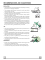
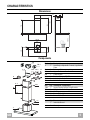
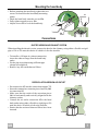
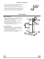
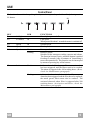
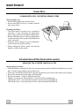
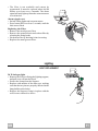
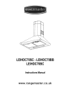
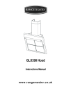
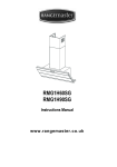
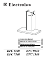
GB Instruction Manual
3
ES Manual de instrucciones
12
DE Bedienungsanleitung
21
PT Manual de Instruções
30
EFC 6540
EFC 7540
EFC 9540
EFC 1540
Dear Customer,
If you follow the recommendations
contained in this Instruction Manual, your
appliance will give you constant high performance and will remain efficient for
many years to come.
CONTENTS
RECOMMENDATIONS AND SUGGESTIONS
4
CHARACTERISTICS
5
INSTALLATION
6
USE
9
MAINTENANCE
GB
10
3
RECOMMENDATIONS AND SUGGESTIONS
INSTALLATION
• The manufacturer will not be held liable for any damages resulting
from incorrect or improper installation.
• The minimum safety distance between the cooker top and the
extractor hood is 650 mm.
• Check that the mains voltage corresponds to that indicated on the
rating plate fixed to the inside of the hood.
• For Class I appliances, check that the domestic power supply
guarantees adequate earthing.
Connect the extractor to the exhaust flue through a pipe of minimum
diameter 120 mm. The route of the flue must be as short as possible.
• Do not connect the extractor hood to exhaust ducts carrying
combustion fumes (boilers, fireplaces, etc.).
• If the extractor is used in conjunction with non-electrical appliances
(e.g. gas burning appliances), a sufficient degree of aeration must
be guaranteed in the room in order to prevent the backflow of exhaust
gas. The kitchen must have an opening communicating directly with
the open air in order to guarantee the entry of clean air.
USE
• The extractor hood has been designed exclusively for domestic use
to eliminate kitchen smells.
• Never use the hood for purposes other than for which it has ben
designed.
• Never leave high naked flames under the hood when it is in operation.
• Adjust the flame intensity to direct it onto the bottom of the pan only,
making sure that it does not engulf the sides.
• Deep fat fryers must be continuously monitored during use:
overheated oil can burst into flames.
• The hood should not be used by children or persons not instructed in
its correct use.
650 mm min.
MAINTENANCE
• Switch off or unplug the appliance from the mains supply before
carrying out any maintenance work.
• Clean and/or replace the Filters after the specified time period.
• Clean the hood using a damp cloth and a neutral liquid detergent.
GB
4
CHARACTERISTICS
650 min.
60
740
870
1200
64
42
Dimensions
598-898
300
490
260
108
150
Components
15
14.1
7.3
12a 7.2.1
9
2.1
12c
2
2.2
11
12a
11
Ref.
1
2
2.1
2.2
9
14.1
15
Q.ty Product Components
1 Hood Body, complete with: Controls, Light, Blower,
Filters
1 Telescopic Chimney comprising:
1 Upper Section
1 Lower Section
1 Reducer Flange ø 150-120 mm
2 Air Outlet Connection Extension
1 Air Outlet Connection
Ref. Q.ty Installation Components
7.2.1
2 Upper Chimney Section Fixing Brackets
7.3
1 Air Outlet Connection Support
11
6 Wall Plugs
12a
6 Screws 4,2 x 44,4
12c
6 Screws 2,9 x 9,5
Q.ty Documentation
1 Instruction Manual
1 Warranty
1
GB
5
INSTALLATION
1÷2
Wall drilling and bracket fixing
650 min.
12a
116 116
320
11
X
7.2.1
Wall marking:
• Draw a vertical line on the supporting wall up to the ceiling, or as high as practical, at the centre of
the area in which the hood will be installed.
• Draw a horizontal line at 650 mm above the hob.
• Place bracket 7.2.1 on the wall as shown about 1-2 mm from the ceiling or upper limit aligning the
centre (notch) with the vertical reference line.
• Mark the wall at the centres of the holes in the bracket.
• Place bracket 7.2.1 on the wall as shown at X mm below the first bracket (X = height of the upper
chimney section supplied), aligning the centre (notch) with the vertical line.
• Mark the wall at the centres of the holes in the bracket.
• Mark a reference point as indicated at 116 mm from the vertical reference line and 320 mm above
the horizontal reference line.
• Repeat this operation on the other side.
• Drill ø 8 mm holes at all the centre points marked.
• Insert the wall plugs 11 in the holes.
• Fix the lower bracket 7.2.1 using the 12a screws (4,2 x 44,4) supplied.
• Fix the upper bracket 7.2.1 and the air outlet connection support 7.3 together using the 2 screws
12a (4,2 x 44,4) supplied.
• Insert the two screws 12a (4,2 x 44,4) supplied in the hood body fixing holes, leaving a gap of 5-6
mm between the wall and the head of the screw.
GB
6
Mounting the hood body
• Before attaching the hood body, tighten the two
screws Vr located on the hood body mounting
points.
• Hook the hood body onto the screws 12a
• Fully tighten support screws 12a
• Adjust screws Vr to level the hood body.
Vr
12a
Connections
DUCTED VERSION AIR EXHAUST SYSTEM
When installing the ducted version, connect the hood to the chimney using either a flexible or rigid
pipe ø 150 or 120 mm, the choice of which is left to the installer.
• To install a ø 120 mm air exhaust connection,
insert the reducer flange 9 on the hood body
outlet.
• Fix the pipe in position using sufficient pipe
clamps (not supplied).
• Remove any activated charcoal filters.
ø 150
ø 120
9
RECIRCULATION VERSION AIR OUTLET
• Put connection 15 into the connection support 7.3.
• Insert the connection extension pieces laterally 14.1
in connection 15.
• Make sure that the outlet of the extension pieces
14.1 is horizontally and vertically aligned with the
chimney outlets.
• Connect the air outlet connection 15 to the hood
body outlet using either a flexible or rigid pipe ø 150
mm, the choice of which is left to the installer.
• Ensure that the activated charcoal filters have been
inserted.
GB
14.1
15
ø 150
7
ELECTRICAL CONNECTION
• Connect the hood to the mains through a two-pole
switch having a contact gap of at least 3 mm.
• Remove the grease filters and verify that the
connector of the feeding cable is correctly inserted
in the socket placed on the side of the fan Enlever
les filtres à graisse et s'assurer que le connecteur
Flue assembly
Upper exhaust flue
• Slightly widen the two sides of the upper flue
and hook them behind the brackets 7.2.1, making
sure that they are well seated.
• Secure the sides to the brackets using the 4
screws 12c (2,9 x 9,5) supplied.
• Make sure that the outlet of the extensions pieces
is aligned with the chimney outlets.
Lower exhaust flue
• Slightly widen the two sides of the flue and hook
them between the upper flue and the wall, making
sure that they are well seated.
• Fix the lower part laterally to the hood body using
the 2 screws 12c (2,9 x 9,5) supplied.
GB
7.2.1
12c
2.1
2
2.2
12c
8
USE
Control Panel
The hood can be switched on pushing directly onto the requested speed without firstly having to select
0/1 button.
S1
L
KEY
L
T1
0/1 Light
0/1 Motor
LED
T2
T3
T4
Speed
Speed
Speed
on
on
Fixed
Flashing
S1
Led
Fixed
on
Flashing
GB
T1
T2
T3
T4
FUNCTIONS
Turns lighting on and off.
First speed.
When pressed for about 1 seconds the motor is switched off.
Second speed.
Third speed.
Max. speed
Intensive speed.
Suitable for the strongest cooking vapours and odours.
The function becomes active when the button is pushed
for about 2 seconds. After 10 minutes of functioning it
turns off automatically. This function can be interrupted
by means of pressing any of the buttons.
Indicates that the Metal grease filters saturation alarm
has been triggered, and the filters need to be washed.
The alarm is triggered after 100 working hours. (Reset;
check the Maintenance-paragraph)
indicates that the activated charcoal odour filter saturation
alarm has been triggered, and the filter has to be replaced;
the metal grease filters must also be washed. The
activated charcoal odour filter is triggered after 200
working hours. (Activation and Reset; check the
Maintenance-paragraph)
9
MAINTENANCE
Grease filters
CLEANING METAL SELF- SUPPORTING GREASE FILTERS
Alarm signal reset
• Switch off the lights and extractor motor.
• Press button T3 for at least 3 seconds, until the
leds start to flash.
Cleaning the filters
• The filters must be cleaned every 2 months of
operation, or more frequently for particularly
heavy usage, and can be washed in a dishwasher.
• Remove the filters one at a time by pushing them
towards the back of the group and pulling down
at the same time.
• Wash the filters, taking care not to bend them.
Allow them to dry before refitting.
• When refitting the filters, make sure that the
handle is visible on the outside.
Activated charcoal filter (Recirculation version)
REPLACING THE ACTIVATED CHARCOAL FILTER
Alarm signal activation
• In Recirculation version Hoods, the Filter saturation alarm can be enabled on installation or at a later
date. Turn the Lights and the suction Motor off.
• Disconnect the Hood using the Main switch or the double-pole switch on the mains power supply.
• Restore the connection by pressing and holding T1.
• Release the button. All five LEDs are turned on
• Within 3 seconds press T1 until LEDs T1 and T4 flash in confirmation:
LED flashes twice - Activated charcoal filter saturation alarm ENABLED
LED flashes once - Activated charcoal filter saturation alarm DISABLED
GB
10
• The filter is not washable and cannot be
regenerated. It must be replaced when led S1
flashes or at least every 4 months. The alarm
signal will only light up when the extractor motor
is switched on.
Alarm signal reset
• Switch off the lights and extractor motor.
• Press button T3 for at least 3 seconds, until the
leds start to flash.
Replacing the Filter
• Remove the metal grease filters
• Remove the saturated activated carbon filter by
releasing the fixing hooks
• Fit the new filter by hooking it into its seating
• Replace the metal grease filters.
Lighting
LIGHT REPLACEMENT
20 W halogen light.
• Remove the 2 Screws fixing the Lighting support,
and pull it out of from the Hood.
• Extract the Lamp from the Support.
• Replace with another of the same type, making
sure that the two pins are properly inserted in the
lamp holder socket holes.
• Replace the Support, fixing it in place with the
two Screws removed as above.
GB
11
This appliance conforms to European Low Voltage Directive 73/23/CEE governing electrical safety, European Directive 89/
336/CEE on Electromagnetic Compatibility and Directive 93/68/CEE regarding CE Marking.
Este aparato es conforme con la normativa europea sobre baja tensión C.E.E. 73/23 correspondiente a la seguridad eléctrica
y a las normativas europeas : C.E.E. 89/336 sobre la compatibilidad electromagnética y C.E.E. 93/68 sobre la marca CE.
Dieses Gerät entspricht folgenden EG-Richtlinien: Niederspannungsrichtlinie EWG 73/23 hinsichtlich elektrischer Sicherheit, Richtlinie Elektromagnetische Verträglichkeit EWG 89/336 und Richtlinie EWG 93/68 hinsichtlich der CE-Kennzeichnung.
Este aparelho está em conformidade com a norma europeia acerca da baixa tensão C.E.E. 73/23, respeitante à segurança
eléctrica e com as normas europeias: C.E.E. 89/336 respeitante à compatibilidade electromagnética e C.E.E. 93/68 respeitante
à marcação CE.
436002073_01 - 040204