1
Operator's Manual
ICRRFTSMRN'I
Industrial Electronic
Plunge Router
Double Insulated
Model No.
315.268350
m
Save this manual
future reference
_1_CAUTION:
m
for
• Warranty
f_k_..
Read
• Introduction
•
•
•
•
and
follow all Safety Rules and
Operating Instructions before
first use of this product.
Customer
Help
Line:
972000-989
4-02
• Repair Parts
1-800-932-3188
Sears, Roebuck
and Co., 3333 Beverly Rd. Hoffman
Visit the Craftsman web page: www.Sears.com/craftsman
Unpacking
Adjustments
Operation
Maintenance
Estates,
IL 60179
USA
®
Printed In U.S.A.
DOUBLE INSULATION
is a safety concept in electric
power tools which eliminates the need for the usual
three wire grounded power cord and grounded
supply system. Wherever there is electric current in
the tool there are two complete sets of insulation to
protect the user. All exposed metal parts are isolated
from internal metal motor components
with
protecting insulation.
A
WARNING:
IMPORTANT - Servicing of a tool with double
insulation requires extreme care and knowledge of
the system and should be performed only by a
qualified service technician. For service we suggest
you return the tool to your nearest Sears Store for
repair. Always use original factory replacement parts
when servicing.
A
The double insulated system is
intended to protect the user from shock resulting
from a break in the tool's internal wiring. Observe
all normal safety precautions related to avoiding
electrical shock.
WARNING:
Do not attempt to operate this
tool until you have read thoroughly and
understand completely all instructions, safety
rules, etc. contained in this manual. Failure
to comply can result in accidents involving
fire, electric shock, or serious personal
injury. Save operator's manual and review
frequently for continuing safe operation, and
instructing others who may use this tool.
READ ALLINSTRUCTIONS
•
KNOW YOUR POWER TOOL. Read operator's
manual carefully. Learn its applications and
limitations as well as thespecific potential
hazards related to this tool.
•
GUARD AGAINST
ELECTRICAL
SHOCK by
preventing body contact with grounded surfaces.
For example: Pipes, radiators, ranges,
refrigerator enclosures.
•
•
KEEP GUARDS IN PLACE and in working
order.
KEEP WORK AREA CLEAN. Cluttered areas
and benches invite accidents.
DANGEROUS
•
Everyday eyeglasses have only impact-resistant
lenses; they are NOT safety glasses.
PROTECT YOUR LUNGS. Wear a face or dust
mask if operation is dusty.
•
PROTECT YOUR HEARING. Wear hearing
protection during extended periods of operation.
•
DON'T ABUSE CORD. Never carry tool by cord
or yank it to disconnect from receptacle. Keep
cord from heat, oil and sharp edges.
•
AVOID
•
•
use power tool in damp or wet locations or
expose to rain. Keep work area well lit.
KEEP CHILDREN
AND VISITORS
AWAY. All
visitors should wear safety glasses and be kept
a safe distance from work area. Do not let
visitors contact tool or extension cord.
SECURE WORK. Use clamps or a vise to hold
work. Both hands are needed to operate the
tool.
•
DON'T OVERREACH.
Keep proper footing and
balance at all times. Do not use on a ladder or
IDLE TOOLS.
ENVIRONMENT.
•
gloves and non-skid footwear are recommended
when working outdoors. Wear protective hair
covering to contain long hair and keep it from
being drawn into nearby air vents.
ALWAYS WEAR SAFETY GLASSES.
Don't
•
STORE
When not in use tools
•
•
should be stored in a dry and high or locked-up
place - out of the reach of children.
DON'T FORCE TOOL. It will do the job better
and safer at the rate for which it was designed.
USE RIGHT TOOL. Don't force small tool or
•
attachment
to do the job of a heavy duty tool.
Don't use tool for purpose not intended - for
example - A circular saw should never be used
for cutting tree limbs or logs.
WEAR PROPER APPAREL. Do not wear loose
clothing or jewelry that can get caught in tool's
moving parts and cause personal injury. Rubber
•
•
unstable support.
MAINTAIN TOOLS WITH CARE. Keep tools
sharp at all times, and clean for best and safest
performance.
Follow instructions for lubricating
and changing accessories.
DISCONNECT
TOOLS. When not in use, before
servicing, or when changing attachments,
blades, bits, cutters, etc., all tools should
•
be
disconnected
from power supply.
REMOVE ADJUSTING
KEYS AND
WRENCHES.
Form habit of checking to see that
keys and adjusting wrenches are removed from
tool before turning it on.
Look
for this
symbol toYour
pointsafety
out important
safety precautions.
It means
attention!!!
is involved.
•
•
•
•
•
•
•
•
•
•
•
AVOID ACCIDENTAL STARTING. Don't carry
plugged-in tools with finger on switch. Be sure
switch is off when plugging in.
MAKE SURE YOUR EXTENSION CORD IS IN
GOOD CONDITION. When using an extension
cord, be sure to use one heavy enough to carry
the current your product will draw. An
undersized cord will cause a drop in line voltage
resulting in loss of power and overheating. A
wire gage size (A.W.G.) of at least 14 is
recommended for an extension cord 25 feet or
less in length. A cord exceeding 25 feet is not
recommended. If in doubt, use the next heavier
gage. The smaller the gage number, the
heavier the cord.
OUTDOOR USE EXTENSION CORDS. When
tool is used outdoors, use only extension cords
suitable for use outdoors. Outdoor approved
cords are marked with the suffix W-A, for
example - SJTW-A or SJOW-A.
KEEP CUTTERS CLEAN AND SHARP. Sharp
cutters minimize stalling and kickback.
KEEP HANDS AWAY FROM CUTFING AREA.
Keep hands away from cutters. Do not reach
underneath work while cutter is rotating. Do not
attempt to remove material while cutter is
rotating.
NEVER USE IN AN EXPLOSIVE
ATMOSPHERE. Normal sparking of the motor
could ignite fumes.
INSPECT TOOL CORDS PERIODICALLY and
if damaged, have repaired at your nearest
Sears Repair Center. Stay constantly aware of
cord location.
INSPECT EXTENSION CORDS PERIODICALLY and replace if damaged.
KEEP HANDLES DRY, CLEAN, AND FREE
FROM OIL AND GREASE. Always use a clean
cloth when cleaning. Never use brake fluids,
gasoline, petroleum-based products or any
strong solvents to clean your tool.
STAY ALERT. Watch what you are doing and
use common sense. Do not operate tool when
you are tired. Do not rush.
CHECK DAMAGED PARTS. Before further use
of the tool, a guard or other part that is damaged should be carefully checked to determine
that it will operate properly and perform its
intended function. Check for alignment of
moving parts, binding of moving parts, breakage of parts, mounting, and any other conditions that may affect its operation. A guard or
other part that is damaged should be properly
repaired or replaced by an authorized service
•
•
•
•
•
•
•
•
center unless indicated elsewhere in this
instruction manual.
DO NOT USE TOOL IF SWITCH DOES NOT
TURN IT ON AND OFF. Have defective
switches replaced by an authorized service
center.
INSPECT FOR and remove all nails from
lumber before muting.
DRUGS, ALCOHOL, MEDICATION. Do not
operate tool while under the influence of drugs,
alcohol, or any medication.
WHEN SERVICING USE ONLY IDENTICAL
CRAFTSMAN REPLACEMENT PARTS.
POLARIZED PLUGS. To reduce the risk of
electric shock, this tool has a polarized plug
(one blade is wider than the other). This plug
will fit in a polarized outlet only one way. If the
plug does not fit fully in the outlet, reverse the
plug. If it still does not fit, contact a qualified
electdcian to install the proper outlet. Do not
change the plug in any way.
DO NOT USE TOOL UNDER "BROWN-OUT"
OR OTHER LOW VOLTAGE CONDITIONS.
Also, do not use with any device that could
cause the power supply voltage to change.
WHEN USING THIS ROUTER WITH A
ROUTER TABLE, HELP PREVENT POSSIBLE SERIOUS INJURY BY KEEPING THE
CUTTER GUARDED AT ALL TIMES. Use only
router tables, with guards, that have been
designed for use on routers that are of this
type, size, and weight.
SAVE THESE INSTRUCTIONS. Review them
frequently and use them to instruct others who
may use this tool. If you loan someone this
tool, loan them these instructions also.
,a, WARNING:
Some dust created by power
sanding, sawing, grinding, drilling, and other
construction activities contains chemicals
known to cause cancer, birth defects or other
reproductive harm. Some examples of these
chemicals are:
• lead from lead-based paints,
• crystalline silica from bricks and cement and other
masonry products, and
• arsenic and chromium
lumber.
from chemically-treated
Your risk from these exposures varies, depending on
how often you do this type of work. To reduce your
exposure to these chemicals: work in a well ventilated
area, and work with approved safety equipment, such
as those dust masks that are specially designed to
filter out microscopic particles.
CONGRATULATIONS
AND THANK YOU FOR BUYING
THIS CRAFTSMAN ROUTER. It has been designed,
engineered and manufactured to provide you with Sears
high standard of dependability, ease of operation, and
operator safety. Properly cared for, it will give you years of
rugged, trouble-frae performance.
A
SPECIFICATIONS:
Depth Of Cut
CAUTION: Carefully
read through this entire
operator's manual before using your new muter.
Pay close attention to the Rules For Safe
Operation, Wamings and Cautions. If you use
your muter propedy and only for what it is
intended, you will enjoy years of safe, reliable
service.
Your muter has many features for making muting
operations more pleasant and enjoyable. Safety,
performance and dependability have been given top
pdority in the design of this muter making it easy to
maintain and operate.
FULL ONE YEAR WARRANTY
ON CRAFTSMAN
0-2-1/2 in.
Collet
1/2 in.
Adapter
1/4 in.
Horsepower
Rating
3.5
120 volts, 60 Hz, AC only, 15.0 AMPS
No Load Speed
10,000 - 22,000 RPM
Power Cord
I Net Weight
_,
INDUSTRIAL
10 Ft.
12.8 Lbs.
ELECTRONIC PLUNGE ROUTER
If this Craftsman Industrial Electronic Plunge Router fails due to a defect in material or workmanship within one year
from the date of purchase, Sears will repair it free of charge.
WARRANTY SERVICE IS AVAILABLE
IN THE UNITED STATES.
BY SIMPLY RETURNING THE TOOL TO THE NEAREST SEARS STORE
This warranty gives you specific legal rights, and you may also have other dghts which vary from state to state.
SEARS, ROEBUCK AND CO.
DEPT. 817 WA
HOFFMAN ESTATES, iL 60179
1.
Rules for Safe Operation
............................................................................
2.
Introduction and Product Specifications .........................................................
4
3.
Warranty and Table Of Contents ....................................................................
4
4.
Unpacking ......................................................................................................
5
5.
Features ......................................................................................................
6.
Adjustments
7.
Operation ................................................................................................
13-18
8.
Maintenance ...........................................................................................
19-23
9.
Exploded View and Repair Parts List ......................................................
24-25
10.
Parts Ordering / Service ...............................................................................
..............................................................................................
2-3
5-7
8-12
26
Your new plunge router comes fully assembled. After removing it from the box, inspect it carefully to make sure that it is
not damaged and that no parts are missing. See Figure 1. The following accessodes should also be included in the box:
1.
15/16 in. Wrench
2.
1/4 in. Adapter
=,_
WARNING:
If any parts are missing, do not
operate your router until the missing parts are
replaced. Failure to do so could result in
possible sedous personal injury.
Your electronic router is a versatile woodworking tool which will give you years of trouble-free performance. It is engineered with the professional in mind, but its ease of operation allows the amateur to produce work which is beautiful and
precise.
3.5 HORSEPOWER
MOTOR
Your router has a powerful 3.5 horsepower motor with
sufficient power to handle the toughest routing jobs. The
motor also has extemally accessible brushes for ease of
servicing.
SOFT
START
The soft start feature builds motor RPM gradually to
minimize start-up torque. Pressing or releasing the "onoff" tdgger will turn your router on or off.
DEPTH
CONTROL
KNOB
A large depth control knob makes precise depth of cut
changes possible. It also is very helpful when making
depth of cut changes with your router mounted upside
down on a router table.
DEPTH STOP SYSTEM
The depth stop block located on the base of your router
provides three adjustable stops and three fixed stops for
quick depth of cut changes. A depth adjustment scale
makes quick adjustments to depth of cut changes possible. The spring loaded adjustment knob quick releases
stop bar by depressing center of knob.
1/4 IN. AND 1/2 IN. SHANK CAPACITY
Your router has a 1/2 in. diameter collet that accepts
cutters with 1/2 in. shanks. A 1/4 in. adapter has been
provided so that cutters with 1/4 in. shank bits can also be
used.
CHIP
SHIELD
A clear plastic see-through chip shield has been provided
on the base of your router for protection against flying
dust and chips. It is designed to fit the front opening of the
router base.
POSILOCK
SPINDLE
LOCK
A posilock spindle lock secures the spindle so that only
one wrench is needed to loosen collet nut and change
cutters. A spindle lock indicator light alerts you that
spindle is locked if you connect router to power supply
before unlocking spindle. Note: Your router will not run if
spindle is locked.
"LOCK-ON"
FEATURE"
Your router is equipped with a "lock-on" feature that is
convenient when continous operation for extended
periods of time is required.
LARGE HANDLES
Your router has large oversized handles for easy handling
and maintaining proper control when routing. The left
handle allows you to set cutter depth of cut when making
plunge cuts, while the right handle provides easy access
to the "on-off" trigger, "lock-on" button, and vadable speed
control selector. The handles have also been designed so
that they are comfortable and easy to grasp when
operating in different positions or at different angles.
VARIABLE SPEED SWITCH WITH
ELECTRONIC SPEED CONTROL
(Feedback
Switch)
Your router has advanced electronic features, designed to
assist you in getting the maximum use from your router.
By making proper speed selections, your router can be
adjusted to specfic routing needs. This eliminates much of
the guess work previously needed to perform a given job.
Both the experienced and inexperienced router users
benefit, obtaining professional like results with fewer job
errors.
The variable speed control allows the router speed to be
adjusted from 10,000 to 22,000 rpm. The variable speed
control selelctor is conveniently located inside the dght
handle near the operator's thumb or hand.
The electronic feature of your router introduces the
flexibility of adjusting the motor speed to required job
conditions. An electronic speed control module senses the
load applied to the motor, and increases or decreases
motor voltage to compensate for and maintain desired
RPM
Speed can be set according to the approximate cutter
diameter you will be using and to the hardness of the
material being cut. The best cuts are made when the
cutter is fed through material at the proper rate of feed.
KNOW YOUR
ELECTRONIC
ROUTER
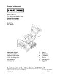
Beforeattemptingto useyour router,familiarize yourselfwith all operatingfeatures and safety requirements.See Figures
1 and 2.
WARNING:
Do not allow familiarity with your router to make you careless, Remember that a careless
fraction of a second is sufficient to inflict severe injury.
DEPTH CONTROL KNOB
FRONT VIEW OF ROUTER
SPINDLE LOCK
INDICATOR LIGHT
POSILOCK
SPINDLE LOCK
LOCKHANDLE
SWITCH HANDLE
PLUNGE
RELEASE
ACTUATOR
VARIABLE SPEED
CONTROLSELECTOR
SCALE
(INCH AND METRIC)
RESET
INDICATOR
ADJUSTMENT KNOB
(DEPRESSING CENTER OF KNOB
QUICK RELEASES STOP BAR)
STOP BAR
STOP SCREW
CHIP SHIE
5/16-18 I
NUT
ADAPTER
1/4 in.
15/16 in. WRENCH
DEPTH STOP BLOCK
_URRE_
DEPTH STOP BLOCK ROTATES
FOR DEPTH OF CUT CHANGES
Fig. 1
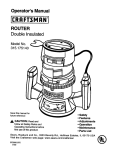
REAR VIEW OF ROUTER
DEPTH CONTROLKNOB
VARIABLE SPEED
CONTROL SELECTOR
POWER CORD
LOCK
HANDLE
"LOCK-ON'
BUTTON
"ON-OFF
TRIGGER
SWITCH HANDLE
PLUNGE
SPEED
SELECTION CHART
ACTUATOR
5116-18 UNC-2B
ROUTER BASE
FLANGE
SUBBASE
COLLETNUT
Fig. 2
ELECTRICAL
CONNECTION
Your router has a precision built electric motor. It should be connected to a power supply that Is 120 volts, 60 Hz, AC
only (normal household current). Do not operate this tool on direct current (DC). A voltage drop of more than 10
percent will cause a loss of power and the motor will overheat. If your tool does not operate when plugged into an outlet,
double-check the power supply.
WARNING:
The operation of any power tool can result in foreign objects beingthrown into your eyes,
which can result in severe eye damage. Before beginning power tool operation, always wear
safety goggles or safety glasses with side shields and a full face shield when needed. We
recommend Wide Vision Safety Mask for use over eyeglasses or standard safety glasses
with side shields, available at Sears Retail Stores. Always wear eye protection which Is
marked to comply with ANSI Z87.1.
Page 7
A
WARNING:
Your router should never be
connected to power supply when you are
assembling parts, making adjustments,
installing or removing cutters, or when not in
use. Disconnecting your router will prevent
accidental starting that could cause sedous
injury.
INSTALLING/REMOVING
SPINDLE LOCK
INDICATOR LIGHT POSILOCK
SPINDLE LOCK
TOLOCK
TO
CUTrERS
See Figures 3, 4, and 5.
• UNPLUG YOUR ROUTER.
WARNING:
Failure to unplug your router
could result in accidental starting causing serious
injury.
•
Place the posilock spindle lock into lock position. See
Figure 3. Note: If spindle does not lock, turn collet nut
with wrench, applying pressure at the same time to the
spindle lock with your thumb or finger. When lock
mechanism engages with notch in spindle, spindle lock
will slide into lock position.
A
CUTTER
COMBINA_ON
WRENCH
COLLET
NUT
WARNING:
To prevent damage to the
spindle or spindle lock, do not attempt to engage
spindle lock while motor is running. Always allow
motor to come to a complete stop and unplug it
before engaging spindle lock.
•
Place router upside down on workbench or lay it face
down on its side in order to gain easy access to collet
nut.
•
Place 15/16 in. wrench provided through back of router
base onto collet nut and turn counterclockwise to
loosen, See Figure 4.
A
Fig. 3
WARNING:
If you are changing a cutter
immediately after use, be careful not to touch the
cutter or collet with your hands or fingers. They will
get burned because of the heat buildup from
cutting.
®
TO TIGHTEN
COLLET NUT,
TO LOOSEN
COLLET NUT
Fig. 4
INSTALLING/REMOVING
(Continued)
•
1/2 In. COLLET
ASSEMBLY
CUI"I'ERS
If installing cutter for the first time, it can be installed
once collet nut is loose. If changing cutters, cutter will
easily slip from collet after loosening collet nut.
COLLET
•
The 112 in. collet is machined to precision tolerances to
fit cutters with 1/2 in. diameter shanks. As previously
mentioned, a 1/4 in. adapter has also been provided
with your router so that cutters with 1/4 in. shank bits
can be used.
•
To use cutters with 1/4 in. shank bits, insert the 1/4 in.
adapter provided inside 1/2 in. collet. See Figure 5.
•
Insert shank of cutter into collet until shank bottoms
out, then pull it out 1/16 in. to allow for expansion when
the bit gets hot.
•
Tighten the collet nut securely by turning with the
wrench provided. See Figure 4.
WARNING:
Do not use cutters with
undersized shanks. Undersized shanks will not
tighten properly and could be thrown from tool
causing injury,
•
Place posilock spindle lock back in unlock position.
Otherwise, interlocking mechanism of spindle lock will
not let you turn your router on. If you forget, the
spindle lock Indicator light will alert you that
spindle is still locked when you connect router to
power supply.
1/4 In.
ADAPTER
CUTTER WITH
1/4 In. SHANK DIAMETER
Fig. 5
A
Page 9
WARNING:
Do not use cutters with
undersized shanks. Undersized shanks will not
tighten properly and could be thrown from tool
causing injury,
DEPTH OF CUT ADJUSTMENTS
See Figures 6, 7, and 8.
PLUNGE
RELEASE
ACTUATOR
When routinga groove thatis too deep to safelycut in one pass,
itis bestto make the cut in several pasees. We recommendthat
severalpasses be made to reach deeper cuts.
Proper depth of cut depends on several factors: horeepower of router motor, type of cutter being used, and type
of wood being routed. A lightweight, low horsepower
router is designed for making shallow cuts. A router with
high horsepower rating can safely cut deeper. Small bits,
such as 1/4 in. shank veining bits with 1/16 in. cutting
diameters, are designed to remove only small amounts of
wood. Large bits, such as 1/2 in. shank straight-flute bits,
are made to remove larger amounts of wood in a single
pass. Cuts can be made deeper in soft woods, such as
white pine, than in tough hardwoods, like oak or maple.
Based upon these considerations, choose a depth of cut
that will not place excessive strain on router motor. If you
find that extra force is needed or that the motor speed
slows down considerably, turn off router and raise the bit.
Then, make the cut in two or more passes.
/
HANDLE
Fig. 6
DEPTH
CONTROL
KNOB
TO SET DEPTH OF CUT
•
HANDLE
UNPLUG YOUR ROUTER.
PLUNGE
LOCK
ACTUATOR
WARNING:
Failure to unplug your router
could result in accidental starting causing
serious injury.
•
•
•
•
•
•
•
•
•
•
•
SQUEEZE
TO LOCK
STOP
FLANGE
Raise cutter by depressing plunge release actuator.
See Figure 6.
Adjust depth control knob until cutter is inside router
subbase. See Figure 7.
Place router on a flat surface..
INSIDE SUBBASE
Lower router until tip of cutter barely touches flat
surface. See Figure 8.
Squeeze plunge lock actuator to lock cutter at "zero"
depth of cut. Note: If desired, adjust depth control knob
until hex nut comes in contact with stop flange. This
will provide a positive stop at "zero" depth of cut.'
Rotate depth stop block to desired position, loosen lock
knob, then turn adjustment knob until stop bar touches
stop screw on depth stop block.
Slide zero-reset indicator up or down the scale on stop
bar until white line on zero-reset indicator aligns with a
desired reference point. For example, align white line
with 1 in. mark on the scale.
Next, turn adjustment knob in the opposite direction,
lifting stop bar to obtain desired depth of cut. See
Figure 8. For example, if setting 1/8 in. depth of cut, the
zero-reset indicator will move 1/8 in. from the 1 in.
reference point. Tighten knob securely.
Position your router so that the cutter can extend below
the subbase for desired depth setting.
Depress plunge release actuator.
Grasp handles and lower router until stop bar contacts
stop screw. Squeeze plunge lock actuator, locking
cutter at desired depth of cut. See Figure 9.
Paoe 10
DEPTH
Fig. 7
ZERO
RESET
INDICATOR
KNOB
SCALE
LOCK
KNOB
DEPTH STOP BLOCK
(TURRET)
Fig. 8
DEPTH CONTROL KNOB
DEPTH
CONTROL
See Figure 9.
Fine adjustments can be made to the depth of cut by use of
the depth control knob. Another primary use of the depth
control knob is setting depth of cut when router is mounted
upside down on a router table. Note: The weight of the
router plus the awkward position it is in when mounted to a
router table make it necessary to use depth control knob.
TO SET DEPTH OF CUT WITH DEPTH
CONTROL
KNOB
B UNPLUG YOUR ROUTER.
WARNING:
Failure to unplug your router
could result in accidental starting causing serious
injury.
STOP
B Loosen lock knob and turn adjustment knob so that
stop bar is not touching stop screws or fixed stops.
• Depress plunge release actuator and allow router to
retum to it's uppermost position against hex nut.
• Plunge router until cutter reaches the approximate
desired depth of cut. Then squeeze plunge lock
actuator, temporarily locking cutter at desired depth of
cut.
• Turn depth control knob clockwise until hex nut seats
against stop flange. DO not overtlghten hex nut
against stop flange.
• Depress plunge release actuator and turn depth control
knob until cutter reaches desired depth of cut. Always
make sure plunge lock is released and router Is
free before setting depth of cut with depth control
knob.
•
•
•
CUTTER EXTENDED
BELOW SUBBASE
HEX NUT
I
Fig. 9
SWITCH
HANDLE
ESET
INDICATOR
I
;K KNOB
ADJUSTMENT
KNOB
STOP BAR
Squeeze plunge lock actuator, locking cutter at desired
depth of cut.
Turn adjustment knob and adjust stop bar until it
touches the desired stop screw or fixed stop.
Tighten lock knob securely.
E STOP SCREW
JT
D STOP
STOP BLOCK(TURRE_
Depth control knob is spring loaded against hex nut. If you
adjust it too far and it pops off threaded rod, refer to
DEPTH CONTROL KNOB ADJUSTMENTS in
ROUTER BASE
Fig. 10
maintenance section for proper reassembly.
TO SET DEPTH
DEPTH
•
UNPLUG YOUR ROUTER.
•
Loosen lock knob and turn adjustment knob clockwise,
raising stop bar to it's highest position.
Determine which stop, adjustable or fixed, to use for
the desired depth of cut. A combination of the two stop
types can be used if required for a specific job. If using
the adjustable stops, the stop screw on each stop can
be adjusted to the desired height by loosening hex nut
with a 3/8 in. wrench, and turning it in or out with your
fingers. Secure stop screw in position by retightening
hex nut with wrench. Do not overtighten hex nut. Set
stops to desired heights, spreading the entire depth of
cut over the number of stops used.
Rotate depth stop block until the highest depth stop is
aligned with the stop bar.
STOP SYSTEM
See Figure 10.
The depth stop block located on the base of your router
makes it possible to make deep or heavy cuts in
successive passes by use of preset depth of cut changes.
Both fixed and adjustable stops are provided, making
depth of cut changes quick and easy. The depth stop
block, also known as a revolving turret, rotates on a ball
detent design in the router base.
A preset cutting depth is achieved by plunging router until
stop bar comes in contact with the stop screw or fixed
stop on depth stop block.
The fixed stops are approximately 1/8 in. apart. The
adjustable stops have screws that may be adjusted
approximately 1/2 in,
•
STOP BLOCK SETTINGS
DEPTH STOP SYSTEM (Continued)
•
•
•
•
•
•
Raise cutter by depressing plunge release actuator.
Place router on flat surface, and lower router until tip of
cutter barely touches flat surface.
Squeeze plunge lock actuator to lock cutter at "zero"
depth of cut.
Turn adjustment knob counterclockwise to lower stop
bar against the stop, then tighten lock knob securely.
The highest stop now becomes the "zero' depth of cut
setting.
Depress plunge release actuator and raise router.
Rotate stop block so that next highest depth stop aligns
with stop bar. This locates cutter for the initial pass.
Rotate depth stop block after each pass. Make as many
sucessive passes as needed to obtain desired depth of
cut, progressively lowering router to next depth of cut
RESET
INDICATOR
-STOP
BAR
)E POINT
ADJUSTMENT KNOB
(PUSHIN TO QUICK
RELEASE STOP BAR)
setting with each pass.
ZERO
RESET
Fig. 11
INDICATOR
See Figure 11.
SPEED
The zero reset indicator allows you to use the scale
provided on the housing to make quick depth of cut
changes to existing depth of cut settings. Simply choose a
reference point on the scale and slide zero reset indicator
up or down scale the distance required for new depth of
cut. Then change stop bar position by loosening lock knob
and turning adjustment knob until white line on zero reset
indicator moves back to reference point. Tighten lock
knob securely to lock stop bar in new position. The cutter
position will now increase or decrease the exact distance
the stop bar was adjusted.
Remember: Each mark on the inch scale indicates a 1/32
SELECTION
CHART
CUTTER SIZE
I
MAT'L
SOFT
I
I
I
I I
MED,U.
HARP
VERY
II I/4 . 3/8. ,/2 n 3/4 1
I
HARD
II
II
II
I
D'E
I
C-D
I
R'C
E
I
O-E I
D
I
F
E
c
I
I
_
c;
I
I
s-¢
c
A-B
I
A
TOINCREASE
I
B
I
I
I
TO DECREASE
inch change in depth setting while each mark on the metdc
scale equals a lmm change in depth setting; depth control
knob should be used for making precise adjustments to
depth of cut; and depressing center of depth adjustment
knob quick releases stop bar.
VARIABLE
SPEED
CONTROL
SELECTOR
CONTROLSELECTOR
See Figure 12.
Your router has a variable speed control selector designed
to allow operator control of speed and torque limits. You
can make speed selections best suited to the type of cut,
the material being cut, and the size of bit being used. The
variable speed control selector allows you to adjust router
speed from 10,000 to 22,000 rpm. There is a six step scale
lettered A to F on the vadable speed control selector. To
increase the speed and torque of your router, turn the
vadable speed control selector to a higher setting.Turn to a
lower setting to decrease speed and torque. Note: If you
do not want to use the vadable speed control selector, turn
to the highest possible setting, and the feature will not be
active.
The speed selection chart shown gives suggested speed
settings based on the diameter of the cutter and the type
of material being routed.
Fig. 12
PRACTICE
BEFORE
ACTUAL
USE
See Figure 12.
We suggest that you practice with the vadable speed
feature of your router before installing a cutter and making
cuts in wood.
PAne 1; )
A
WARNING:
Always wear safety goggles or
safety glasses with side shields when using
router. Failure to do so could result in dust,
shavings, chips, loose particles, or foreign objects
being thrown in your eyes causing possible
sedous injury. If operation is dusty, also wear a
face or dust mask.
SWITCH HANDLE
"LOCK-ON"
BUTTON
See Figure 13.
The "on-off" trigger of your muter is equipped with a "lockon" feature which is convenient when operating for extended pedods of time. The "look-on" button is located in
the upper portion of the "on-off"tdgger. It works similar to
a rocker switch. To lock on, fully depress "on-off" tdgger,
then depress 'lock-on" button in top of "on-o_ tdgger and
release. You will feel the "lock-on" button as it snaps "onoff' tdgger into lock position. To release the lock, depress
protruding portion of the 'lock-on" button.
A
WARNING:
TO RELEASE
LOCK-ON
ON-OFF
"ON-OFF"
TRIGGER
Before connecting muter to
power supply source, always check to be sure
switch is not in "lock-on" position. Failure to do so
could result in accidental starting of your router
causing possible serious injury.
ROUTING
See Figure 14.
For ease of operation and maintaining proper control, your
router has two handles, one on each side of the router
base. When using your router hold it firmly with both
hands as shown in figure 14.
Before starting router, make sure cutter is securely
tightened in collst nut and that depth of cut is propedy set.
Turn router on and let motor build to its full speed, then
gradually plunge or feed cutter into workpiece. DO NOT let
the cutter contact workpiece before turning on muter and
allowing it to develop full speed.
Remain alert and watch what you are doing. DO NOT
operate muter when fatigued.
FEED DIRECTION
When routing, the cutter rotates clockwise. Therefore, you
should feed the router into the workpiece from left to dght.
When fed from left to dght, the rotation of the cutter pulls
the router against the workpiece. If fed in the opposite
direction, the rotation forces of the spinning bit will tend to
throw the router away from the workpiece. This could
cause loss of control of your router.
RATE OF FEED
IMPORTANT: The whole "secret" of professional muting
and edge shaping lies in making a careful set-up for the
cut to be made and in selecting the proper rate of feed.
The proper rate of feed depends on several factors: the
hardness and moisture content of the wood, the depth of
Fig. 14
cut, and the cutting diameter of the bit. When cutting
shallow grooves in soft woods such as pine, a faster rate
of feed can be used. When making deep cuts in hardwoods such as oak, a slower rate of feed will be required.
The best rate of feed is one that does not slow down the
router motor more than one-third of its no-load speed. If
the muter is fed too fast, it will take large chips out of the
wood and leave gouge marks. If the router is fed too slow,
it will scorch or burn the wood.
Page 13
PROPER
FEEDING
The right feed is neither too fast nor too slow. It is the rate
at which the bit is being advanced firmly and surely to
produce a continuous spiral of uniform chips -- without
hogging into the wood to make large individual chips or, on
the other hand, to create only sawdust. If you are making a
small diameter, shallow groove in soft, dry wood, the
proper feed may be about as fast as you can travel your
router along your guide line. On the other hand, if the bit is
a large one, the cut is deep or the wood is hard to cut, the
proper feed may be a very slow one. Then, again, a
cross-grain cut may require a slower pace than an identical with grain cut in the same workpiece.
TOO FAST
There is no fixed rule. You will learn by experience from
practice and use. The best rate of feed is determined by
listening to the sound of the router motor and by feeling
the progress of each cut. If at all possible, always test a
cut on a scrap piece of the workpiece wood, beforehand.
SPEED
SELECTION
In general, if the material being cut is hard, the cutter size
is large, or the depth of cut is deep, then your router
should be run at slower speeds. When these situations
exist, turn the variable speed control selector until the
desired speed is reached. NOTE: Carbide cutters cut at
higher speeds than steel cutters and should be used when
cutting very hard materials.
FORCE
FEEDING
Clean, smooth routing and edge shaping can be done only
when the bit is revolving at a relatively high speed and is
taking very small bites to produce tiny, cleanly severed
chips. If your router is forced to move forward too fast, the
RPM of the bit becomes slower than normal in relation to
its forward movement. As a result, the bit must take bigger
bites as it revolves. "Bigger bites" mean bigger chips, and
a rougher finish. Bigger chips also require more power,
which could result in the router motor becoming overloaded.
Under extreme force-feeding conditions the relative RPM
of the bit can become so slow -- and the bites it has to
take so large -- that chips will be partially knocked off
(rather than fully cut off), with resulting splintering and
gouging of the workpiece. See Figure 15.
Your Craftsman router is an extremely high-speed tool
(10,000 - 22,000 RPM no-load speed), and will make
clean, smooth cuts if allowed to run freely without the
overload of a forced (too fast) feed. Three things that
cause "force feeding" are bit size, depth-of-cut, and
workpiece characteristics. The larger the bit or the deeper
the cut, the more slowly the router should be moved
forward. If the wood is very hard, knotty, gummy or damp,
the operation must be slowed still more.
TOO SLOW
Fig. 15
You can always detect "force feeding" by the sound of the
motor. Its high-pitched whine will sound lower and stronger
as it loses speed. Also, the strain of holding the tool will be
noticeably increased.
TOO SLOW FEEDING
It is also possible to spoil a cut by moving the router
forward too slowly. When it is advanced into the work too
slowly, a revolving bit does not dig into new wood fast
enough to take a bite; instead, it simply scrapes away
sawdust-like particles. Scraping produces heat, which can
glaze, burn, or mar the cut -- in extreme cases, san even
overheat the bit so as to destroy its hardness.
In addition, it is more difficult to control a router when the
bit is scraping instead of cutting. With practically no load
on the motor the bit will be revolving at close to top RPM,
and will have a much greater than normal tendency to
bounce off the sides of the cut (especially, if the wood has
a pronounced grain with hard and soft areas). As a result,
the cut produced may have rippled, instead of straight
sides. See Figure 15.
"Too-slow feeding" can also cause your router to take off in
a wrong direction from the intended line of cut. Always
grasp and hold your router firmly with both hands
when routing.
You can detect "too-slow feeding" by the runaway
too-highly pitched sound of the motor; or by feeling the
"wiggle" of the bit in the cut.
DEPTH
OF CUT
DEPTH
OF CUT
As previously mentioned, the depth of cut is important
because it affects the rate of feed which, in tum, affects
the quality of a cut (and, also, the possibility of damage to
your bit). A deep cut requires a slower feed than a shallow
one, and a too deep cut will cause you to slow the feed so
much that the bit is no longer cutting, it is scraping, instead.
Making a deep cut is never advisable. The smaller bits -especially those only 1116 inch in diameter -- are easily
broken off when subjected to too much side thrust. A large
enough bit may not be broken off, but if the cut is too deep
a rough cut will result -- and it may be very difficult to
guide and control the bit as desired. For these reasons, we
recommend that several passes be made to reach deeper
cuts. See Figure 16.
WIDTH OF CUT
Fig.16
2ND.
2ND. iASs_IS
To make deeper cuts it is therefore necessary to make as
many successive passes as required, Iowedng the bit for
each new pass. In order to save time, do all the cutting
necessary at one depth setting, before Iowedng the bit for
the next pass. This will also assure a uniform depth when
the final pass is completed. See Figure 17.
DIRECTION
_'-
i
PASS
PASS
Fig. 17
ROUTER FEED
OF FEED AND THRUST
See Figure 18.
The router motor and bit revolve in a clockwise direction.
This gives the tool a slight tendency to twist (in your
hands) in a counterclockwise direction, especially when
the motor revs up (as at starting).
Because of the extremely high speed of bit rotation dudng
a "proper feeding" operation, there is very little kickback to
contend with under normal conditions. However, should
the bit strike a knot, hard grain, foreign object, etc. that
would affect the normal progress of the cutting action,
there will be a slight kickback -- sufficient to spoil the
trueness of your cut if you are not prepared. Such a
kickback is always in the direction opposite to the direction
of bit rotation.
D
ROUTER FEED
ROTATION
DIRECTION
Fig. 18
GUIDE OUTSIDE
ROTATION
_
THRUST_
To guard against such a kickback, plan your set-up and
direction of feed so that you will always be thrusting the
tool -- to hold it against whatever you are using to guide
the cutin the same direction that the leading edge of
the bit is moving. In short, the thrust should be in a direction that keeps the sharp edges of the bit continuously
biting straight into new (uncut) wood.
FEED
)
GUIDE
GUIDE INSIDE
ROUTING
Whenever you are routing a groove, your travel should be
in a direction that places whatever guide you are using at
the right-hand side. In short, when the guide is positioned
as shown in the first part of Figure 19, tool travel should be
left to right and counterclockwise around curves. When the
guide is positioned as shown in the second part of Figure
19 tool travel should be dght to left and clockwise around
curves. If there is a choice, the first set-up is generally the
THRUST
ROTATION __
/
FEED
Fig. 19
easiest to use. In either case, the sideways thrust you use
is against the guide.
Page 15
EDGEROUTING
Race muter on workpiece, making sure the muter bit does
not contact workpiece. Turn muter on and let motor build to
its full speed. Begin your cut, gradually feeding cutter into
workpiece.
A
WARNING:
Keep a firm grip on router with
both hands at all times. Failure to do so could
result in loss of control leading to possible serious
injury.
PILOT
TOP EDGE SHAPING
Upon completion of cut, turn motor off and let it come to a
complete stop before removing router from work surface.
ROUTER
WORK
WARNING:
Never pull router out of work and
place upside down on work surface before the cutter
stops.
EDGING
WITH
PILOT
BITS
See Figure 20.
Rabbets and molded edges can be cut using piloted
cutters. The pilot extends below the cutter. Some pilots
are solid extensions of the cutter. Others are ball beadng
guides that are fastened to the end of the cutter. The pilots
allow the cutters to tum while the pilot follows the edge of
the workpiece.
GUIDE
WHOLE
Arbor-type bits with pilots are excellent for quick, easy,
edge shaping. They will follow workpiece edges that are
either straight or curved. The pilot prevents the bit from
making too deep a cut; and holding the pilot firmly in
contact with the workpiece edge throughout prevents the
cut from becoming too shallow.
,.
I-
EDGE
SHAPING
Fig. 20
°
Whenever the workpiece thickness together with the
desired depth of cut (as adjusted by router depth setting)
are such that only the top part of the edge is to be shaped
(leaving at least a 1/16 inch thick uncut portion at bottom),
the pilot can dde against the uncut portion, which will serve
to guide it. See Figure 20. However, if the workpiece is
too thin or the bit set too low so that there will be no uncut
edge to ride the pilot against, an extra board to act as a
guide must be placed under the workpiece. This "guide"
board must have exactly the same contour -- straight or
curved -- as the workpiece edge. If it is positioned so that
its edge is flush with the workpiece edge, the bit will make
a full cut (in as far as the bit radius). On the other hand, if
the guide is positioned as shown in Figure 20 (out from the
workpiece edge), the bit will make less than a full cut -which will alter the shape of the finished edge.
NOTE: If desired, any of the piloted bits can be used
without a pilot for edge shaping with guides, as preceding.
Also, the size (diameter) of the pilot that is used determines the maximum cut width that can be made with the
pilot against the workpiece edge (the small pilot exposes
all of the bit; the large one reduces this amount by 1/16
inch).
"m'l
6
rl
1/4 IN.TO 1IN.
Fig. 21
When routing all the edges of a panel or board, rout the
end grain first. Any splintedng that occurs at the comers
will then be removed when routing the edge. Start each
side 1/4 in. away from the end. Feed the cutter into the
wood until the pilot contacts the uncut edge. Then, slowly
back the router to shape the comer. Next, move the router
forward to shape the rest of the edge. Be careful to keep
the pilot pressed against the uncut edge. Repeat this
procedure on each side of the panel. Figure 21 shows the
proper sequence of cuts to make when edge muting four
sides of a panel.
Page 16
ROUTING
GROOVES
See Figure 22.
When routing across the face of boards, set router at
desired depth of cut, place the edge of router base against
workpiece, and turn on your router. Slowly feed the cutter
into the workpiece along desired cutline.
DIRECTION
OF CUT I_
WORKPIECE
RABBET
WARNING:
If desired depth of cut is greater
than can be safely cut in one pass, make cuts in two
or more passes.
When routing straight cuts across stock, clamp a
straightedge to the workpiece to use as a guide. Position
the straightedge parallel to the cutline and offset the
distance between the cutting edge of the cutter and the
edge of the router base. Hold the router base against the
straightedge and rout the groove.
UNCUTEDGE
When routing a groove wider than the diameter of the
cutter, clamp a straightedge on both sides of the cutting
line. Position both guides parallel to the desired cutline and
spaced equal distances from the desired edges of the
groove. Rout along one guide; then, reverse direction and
rout along the other guide. Clean out any remaining waste
in the center of the groove freehand.
Page 17
BIT PILOT
Fig. 22
FREEHAND ROUTING
See Figure 23.
When used freehand, your plunge router becomes a
flexible and versatile tool This flexibility makes it possible
to easily rout signs, relief sculptures, etc.
There are two basic techniques for freehand routing:
•
Routing letters, grooves, and pattems into wood.
•
Routing out the background, leaving the letters or
pattern raised above the surface as shown in figure 23.
When freehand routing, we suggest the folowlng:
•
Draw or layout the pattern on workpiece.
•
Choose the appropnate cutter. Note: A core box or Vgroove bit is often used for routing lettem and engraving
objects. Straight bits and ball mills are often used to
make relief carvings. Veining bits are used to carve
small, intricate details.
•
Rout the pattern in two or more passes. Make the first
pass at 25% of the desired depth of cut. This will
provide better control as well as being a quide for the
next pass.
Freehand routing Is an excellent example of how to
use the plunge routing feature of your router:
•
Choose the appropdate cutter, set desired depth of cut,
carefully check set-up, and secure workpiece.
•
Make a test cut in a scrap piece of wood from the same
workpiece if possible.
•
Depress plunge release actuator and raise cutter from
any preset depth of cut. This also permits raising cutter
inside router subbase.
•
Place router on workpiece inside pattern to be muted.
•
Grasp handles securely and depress "on-off" trigger to
start your router.
•
Let motor build to full speed, then gradually plunge
cutter into workpiece until stop bar comes into contact
with stop screw on depth stop block.
•
Squeeze plunge lock actuator to secure depth of cut
setting.
•
Begin routing out the pattern, continuing until a complete pass at this depth of cut has been made.
•
Several cuts that require repositioning of router may be
needed for a particular job. If this situation exists,
depress plunge release actuator and raise cutter inside
muter subbase after each cut, reposition router for next
cut, gradually plunge cutter into workpiece until stop bar
contacts stop screw, squeeze plunge lock actuator and
continue routing.
•
After all cuts have been made, depress plunge release
actuator, raise cutter inside relJter subbase, remove
router from workpiece, release "on-off" trigger, and
allow cutter to come to a complete stop.
Page 18
Fig. 23
A
WARNING:
When servicing use only
identical Craftsman replacement pads, Use of any
other parts may create a hazard or cause product
damage,
GENERAL
Only the parts shown on parts list, page 25, are intended
to be repaired or replaced by the customer. All other parts
represent an important part of the double insulation system
and should be serviced only by a qualified Sears se_ce
technician.
Avoid using solvents when cleaning plastic parts. Most
plastics are susceptible to various types of commercial
solvents and may be damaged by their use. Use clean
cloths to remove dirt, carbon dust, etc.
A
WARNING:
Do not at any time let brake
fluids, gasoline, petroleum-based products,
penetrating oils, etc. come in contact with plastic
pads. They contain chemicals that can damage,
weaken, or destroy plastic.
When electric tools are used on fiberglass boats, sports
cars, wallboard, spackling compounds, or plaster, it has
been found that they are subject to accelerated wear and
possible premature failure, as the fiberglass chips and
grindings are highly abrasive to bearings, brushes,
commutators, etc. Consequently it is not recommended
that this tool be used for extended work on any fiberglass
material, wallboard, spackling compounds, or plaster.
During any use on these materials, it is extremely
important that the tool is cleaned frequently by blowing
with an air jet.
A
WARNING:
Always wear safety goggles, or
safety glasses with side shields dudng power tool
operation or when blowing dust if operation isdusty,
also wear a dust mask.
LUBRICATION
All of the beadngs in this tool are lubricated with a sufficient amount of high grade lubricant for the life of the unit
under normal operating conditions. Therefore, no further
lubrication is required.
Paae lg
BRUSH REPLACEMENT
See Figure 24.
BRUSH ASSEMBLY
Your router has extemally accessible brush assemblies
that should pedodically be checked for wear.
PROCEED AS FOLLOWS
REQUIRED:
•
WHEN REPLACEMENT
BRUSH CAP
IS
BRUSHCAP
UNPLUG YOUR ROUTER.
WARNING:
Failure to unplug your router
could result in accidental starting causing serious
injury.
•
•
Remove brush cap with a screwdriver. Brush assembly
is spdng loaded and will pop out when you remove
brush cap.
Remove brush assembly (brush and spring).
•
Check for wear. If wom, always replace in pairs. Do not
replace one side without replacing the other.
•
Reassemble using new brush assemblies. Make sure
curvature of brush matches curvature of motor and that
brush moves freely in brush tube.
•
Replace brush cap and tighten securely.
Fig. 24
PROPER
EXTENSION CORDS
CARE OF CUTTERS
Get faster more accurate cutting results by keeping cutters
clean and sharp. Remove all accumulated pitch and gum
from cutters after each use.
When sharpening cutters, sharpen only the inside of the
cutting edge. Never grind the outside diameter. Be sure
when sharpening the end of a cutter to gdnd the clearance
angle the same as odginally ground.
PROPER
CARE OF COLLET
The use of any extension cord will cause some loss of
power. To keep the loss to a minimum and to prevent tool
overheating, use an extension cord that is heavy enough to
carry the current the tool will draw.
A wire gage size (A.W.G.) of at least 14 is recommended
for an extension cord 25 feet or less in length. When
working outdoors, use an extension cord that is suitable for
outdoor use. The cord's jacket will be marked WA.
CAUTION: Keep extension cords away from
any routing area and position the cord so that it
will not get caught on lumber, tools, etc., during
routing operation.
From time to time, it also becomes necessary to clean your
collet and collet nut. To do so, simply remove collet/nut
assembly from motor shaft and clean the dust and chips
that have collected. Then return collet/nut assembly to its
original position.
A
Page 20
WARNING:
Check extension cords before
each use. If damaged replace immediately.
Never use tool with a damaged cord since
touching the damaged area could cause
electrical shock resulting in sedous injury.
PLUNGE LOCK ACTUATOR
See Figure25.
COMPRESSION
SPRIN(
ADJUSTMENTS
The plunge lock actuator has been properly set at the
factory and no initial adjustments should be required.
However, after extended use slight readjustment may be
required. If this situation occurs, make adjustments as
follows:
RELEASE
ACTUATOR
PLUNGE
L\ PLUNG_
|I
LOCK"
___.
•
UNPLUG YOUR ROUTER.
WARNING: Failure to unplug your router
could result in accidental starting causing serious
injury.
•
•
•
•
•
•
•
Remove lock handle cover screws and lock handle
cover. See Figure 25.
NOTE THE LOCATION
OF PLUNGE RELEASE
ACTUATOR
AND COMPRESSION
SPRING
IN
HANDLE. Reaeaembly of all parts removed must be
identical In order for plunge lock and plunge release
actuators to function properly,
Loosen hex nut on bottom of plunge lock actuator with a
7116 in. open end wrench.
Loosen socket head screw with a 1/8 in. hex key (allen
wrench). This step is needed to make sure screw is not
making contact with rod in base assembly.
Depress plunge lock actuator until it is flush with handle
as shown in figure 26.
Continue to hold plunge lock actuator flush with handle,
then turn hex key clockwise until socket head screw
touches base assembly rod. IMPORTANT: Do not overtighten screw.
Make sure hex nut remains loose while tightening socket
head screw.
•
Once socket head screw touches base assembly rod,
secure it by tightening hex nut against plunge lock actuator.
•
Do not let socket head screw slip or turn while tightening
hex nut.
/SOCKET
HEAD SCRI
HANDLE
LOCK
HANDLE
COVER
'/16 IN.
WRENCH
HEX NUT
1/8 IN. HEX KE_
(ALLEN WRENCH)
PLUNGE
LOCK
ACTUATOR
Fig. 25
COMPRESSION
SPRING
PEG
PLUNGE
RELEASE
ACTUATOR
ACTUATOR
SLIDE
GROOVE
PLUNGE LOCK
ACTUATOR SHOWN
FLUSH PosmoN
•
Slip compression spring over peg on plunge release
actuator. Then locate tabs on actuator in slide grooves.
Make sure that end of compression spring rests against
wall of stop pocket.
• Carefully replace handle cover and handle cover screws.
Make sure plunge release actuator and compression
spring are properly seated.
• Tighten handle cover screws securely.
When properly adjusted, plunge lock actuator will make
contact with base assembly rod when it is flush with
handle. By squeezing plunge lock actuator past this point,
a friction lock situation occurs. This is what locks your
router at desired depth of cut settings.
The plunge release actuator is spring loaded. When
engaged, it pushes the plunge lock actuator past the flush
point in the opposite direction. This loosens socket head
screw, releasing pressure from rod in base assembly.
Page 21
SOCKET
HEADSCREW
HEX NUT
7/161N.
WRENCH
I_IN.
DUSTBOOT
COVERS BASE
ASSEMBLYROD
HEX KEY
!WRENCH)
Fig. 26
DEPTH CONTROL KNOB ADJUSTMENTS
See Figure 27.
The depth control knob is spring loaded against hex nut to
prevent router motor from accidentally separating from
router base. If depth control knob is tumed too far up
depth adjustment rod, the spring will cause depth control
knob to pop off before hex nut. Do not remove hex nut.
It should remain on depth adjustment rod at all times. This
is especially important when using router upside down on
a router table.
DEPTH
CONTROL
KNOB
TO REPLACE DEPTH CONTROL KNOB:
•
UNPLUG YOUR ROUTER.
WARNING:
Failure to unplug your router
could result in accidental starting causing serious
injury.
•
•
DEPTH
ADJUSTMENT
ROD
Turn hex nut counterclockwise until 1/4 in. of threads
are remaining at the top of depth adjustment rod.
COMPRESSION
SPRIN(
Place compression spring on top of hex nut as shown in
figure 27.
•
Place depth control knob on top of compression spdng
and align tabs on depth control knob with flats on hex
nut.
•
Carefully compress spring by pushing down on top of
depth control knob.
•
With spdng compressed, thread depth control knob
clockwise onto depth adjustment rod.
•
Turn depth control knob until desired depth of cut is
reached.
1/4 IN.
WASHER
TABS
Fig. 27
Do not replace depth control knob without compression
spdng.
A
HEX NUT
WARNING:
Replacing depth control knob
without compression spring could result in depth
control knob and hex nut vibrating off depth ,
adjustment rod during use. This situation could
cause motor to separate from router base, resulting in possible serious personal injury.
P_n_
9_
ROUTER
A
TABLES
WARNING:
Do not use with router tables
that fail to conform to safe wood working
practices and offer proper guarding for the cutter.
Failure to comply can result in an accident
causing possible serious injury.
If mounting your router to a router table, use only the
three 5/16-18 UNC-2B tapped holes provided in the
router base. Use 5/16-18 UNC-2A flat head screws that
are 1-1/8 in. or 1-1/4 in. long when mounting router to a
router table. NOTE: Router subbase must be removed
in order to gain access to the 5/16-18UNC tapped
holes.
,a, WARNING:
DO not use the four 8-32 UNC-2B
subbase screws or the 8-32 UNC-2B tapped
subbase screw holes for mounting router to a
router table. These screws and screw holes will
not secure router to router table properly and
could result in an accident causing possible
serious injury.
The use of Craftsman routers in router tables offered
by other manufacturers
has not been investigated for
compliance with applicable safety standards.
,a, WARNING:
Do not use large router bits for
freehand routing. Use of large router bits when
freehand routing could cause loss of control or
create other hazardous conditions that couldcause
possible serious personal injury.When usingrouter
table, large router bits should be used for edging
only.
HELPFUL HINTS
J
Always wear eye protection when routing.
,/
A safe operator is one who thinks ahead.
•/
Plan each operation before you begin.
,f
Study all safety rules and do the job safely.
J
Don't let familiarity make you careless.
,f
NEVER place your hands in jeopardy.
,f
Always clamp workpiece securely before routing.
J
Make certain clamps can't loosen while in use.
•/
Make set-up adjustments carefully. Then double check. Measure twice and cut once.
J
ProVidef_rsm__ther_perati_nbyc_eaningy_urmuterfrequent_y_Shaker_uter_rb__Wwithanairjett_rem_Ve
sawdust build-up.
J"
Keep cutters clean and properly sharpened.
,f
Check depth of cut settings carefully. Don't waste lumber by making too deep a cut. Make several shallow
passes, lowering the cutter for each new pass.
,/" Test difficult set-ups on scrap = Don't waste lumber.
_/
THINK SAFETY BY THINKING AHEAD,
Page 23
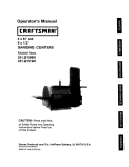
CRAFTSMAN
ROUTER - MODEL NUMBER 315.268350
SEENOTE"A"
15.._
54 -_
-_
28
/
D-.--43
._/
2?
"
I//.
41
NOTE: "A"- The assembly shown represents an important part of the Double Insulated System. To avoid the possibility of alteration or damage to the
system, service should be performed by your nearest Sears Repair Center. Contact your nearest Sears Retail Store.
Page 24
CRAFTSMAN ROUTER - MODEL NUMBER 315.268350
!
The
ROUTER
model ornumber
when ordering
will be found
repairon
pads.
a plate attached to the motor housing. Always mention the model number in all correspondence regarding your i
PARTS LIST
Key
No.
1
2
3
4
5
6
7
8
9
10
11
12
13
14
15
16
17
18
19
20
21
22
23
24
25
26
27
28
29
30
31
32
33
34
35
Part
Number
622167-028
970738-002
970742-001
974433-001
970743-001
970740-001
931744-006
622171-055
970760-001
970758-001
971094-001
970762-001
970736-001
617966-030
970764-001
970875-001
983207-001
981252-001
622167-071
970770-001
931744-063
703493-820
970720-202
622931-008
970734-001
970717-002
970715-002
622347-017
622167-070
970718-002
970719-001
989177-000
970866-002
971137-001
607406-005
DescrlpUon
*
*
*
*
*
Key
No.
Quan.
Retaining Ring ........................................... ".. 1
Torsion Spring ..............................................
1
Stop Plug ......................................................
1
Clamp Bolt ....................................................
1
Keyed Washer ..............................................
1
Screw (#1/4-28 x 1-5/8 in, Hex Soc. Hd.) .... 1
Washer **STD551225 .................................. 1
Hex Hut (#1/4-28) .........................................
1
Lock Actuator ...............................................
1
Lock Handle Cover ....................................... 1
Posirock Label ..............................................
1
Release Actuator ........................ ; ................. 1
Compression Spring ..................................... 1
Screw (#8-10 x 5/8 in. Pan Hd.) ................... 5
Brush Cap ....................................................
2
Brush Assembly ...........................................
2
Data Plate .....................................................
1
Logo Plate ....................................................
1
Retaining Ring ..............................................
4
Zero Reset Indicator ..................................... 1
Washer .........................................................
1
Washer .........................................................
1
Retainer Plate ...............................................
1
Screw (#6-32 x 3/8 in. Fil. Hd.) .................... 2
Compression Spring ..................................... 1
Adjustment Knob ..........................................
1
Lo_:kKnob ....................................................
1
Spring Washer ..............................................
1
Retaining Ring ..............................................
1
Depth Stop Bar .............................................
1
Stop Bar Pinion ............................................
1
Retaining Ring kit .........................................
1
Depth Control Knob ......................................
1
Compression Spring ..................................... 1
Hex Nut (#3/8-16) ......................................... 2
Part
Number
Description
36
37
38
39
706382-817
970732-001
970864-001
614658-010
40
41
970865-001
622183-042
42
43
44
45
46
47
48
49
50
51
52
53
54
55
56
57
58
59
970755-204
970772-001
967711-000
970722-005
705404-801
940021-006
706239-830
622347-019
970712-001
970741-001
970754-001
970723-001
982860-001
982859-001
982897-108
982987-001
982889-001
060721-630
***
60
61
62
060721-530
060721-430
060721-030
***
***
***
63
64
65
972160-001
969357-002
972421-000
972000-989
***
***
***
*
*
*
*
Washer .........................................................
Depth Adjustment Rod .................................
Chip Shield ...................................................
Screw (#8-32 x 3/8 in. Pan Hd.)
**STD510803 ...............................................
Subbase .......................................................
Screw (#8-32 x 3/8 in. Flat Hd.)
**STD510803 ...............................................
Base Assembly .............................................
Compression Spring .....................................
1/4 in. Steel Ball ...........................................
Depth Stop Block (Turret) ............................
Hex Nut (#10-24) ..........................................
Screw (#10-24 x 1/2 in. Cap Soc. Hd.) ........
Washer .........................................................
Spring Washer ..............................................
Shoulder Screw ............................................
Dust Boot ......................................................
Compression Spring .....................................
Guide Pin ......................................................
1/2 in. Collet .................................................
1/2 in. Collet Nut ...........................................
Retaining Ring ..............................................
1/4 in. Adapter ..............................................
Wrench .........................................................
Guide Bushing w/Nut
(1/4 in. x 5/16 in.) .........................................
Guide Bushing w/Nut (1/4 In. x 3/8 in.) ........
Guide Bushing w/Nut (1/2 In. x 518 in.) ........
Guide Bushing w/Nut
(11/32 in. x7/16 in.) .....................................
Guide Bushing Adapter ................................
Optional Roller Guide Assembly ..................
Optional Guide Holder w/Hardware .............
Operator's Manual
* Standard Hardware Item -- May Be Purchased Locally
** Available From DIv. 98 -- Source 980.00
Optional Accessory (Not Shown) -- May Be Purchased For Use On Your New Plunge Router
P_n_
_K
Quan.
1
1
1
1
1
4
1
1
1
1
3
3
1
1
1
2
2
2
1
1
1
1
1
1
1
1
1
1
1
1
For repair of major brand appliances in your own home...
no matter who made it, no matter who sold it!
1-800-4-MY-HOM EsMAnytime, day or night
(1-800-469-4663)
www,sears.com
To bring in products such as vacuums, lawn equipment and electronics
for repair, call for the location of your nearest Sears Parts & Repair Center.
1-800-488-1222
Anytime,
day or night
www.sears.com
For the replacement parts, accessories and owner's manuals
that you need to do-it-yourself, call Sears PartsDirect SM!
1-800-366-PART 6a.m.
- 11p.m.
CST,
(1-800-366-7278)
7 days a week
www.sears.com/partsdirect
To purchase or inquire about a Sears Service Agreement:
1-800-827-6655
7 a.m. - 5 p.m. CST, Mon. - Sat.
Para pedir servicio de reparacibn a domicilio,
y para ordenar piezas con entrega a domicilio:
1-888-SU-HOGAR
SM
Au Canada
pour service
en franc,,ais:
1-877-LE-FOYER _"
(1-877-533-6937)
(1-888-784-6427)
_.a
® Registered
® Sears,
Roebuck
and
Co.
® Marca
Trademark
Registrada
I
wa
/
Marca
Trademark
de F_brica
of Sears,
de Sears,
Roebuck
Roebuck
and
and
Co,
Co.
Manual del Usuario
Tupi Electrbnico Industrial con
Efecto de Embolo
Aislamiento Doble
Modelo N°
315.268350
Garanfia
Introducci6n
Conserve este manual
para referencia futura
A
ATENClON:
Desempaque
Caracterfsticas
Lea cuidadosamente
Ajustes
Funcionamiento
Mantenimiento
todas las Reglas de Seguddad y las
Instrucciones antes de usar esta
herramienta.
Repuestos
N _ de tel_fono
Sears,
Visite
de ayuda a los clientes:
Roebuck
la pdgina
972000-989
4-02
and
Web
Co.,
3333
de Craftsman:
1-800-932-3188
Beverly
Rd.
Hoffman
www.sears.com/craftsman
Estates,
IL 60179
USA
®
Impreso en EE.UU.
EL AISLAMIENTO
DOBLEes unconceptodeseguridad,
en las herramientas mecdnicas eldctricas, que elimina la
necesidad del cordbn normal de tres hilos puesto a tierra
y el sistema de suministro de energfa puesto a tierra. En
cualquier parte en que haya corriente el_ctrica en la
herramienta hay dos juegos completos de aislamiento
para proteger al usuario. Todas las piezas metalicas
expuestas estan aisladas de los componentes mec_nicos
intemos con aislamiento protector.
A
ADVERTENCIA:
IMPORTANTE - La reparacibn de las herramientas con
aislamiento doble requiere extremo cuidado y
conocimiento del sistema y debe ser realizada solamente
pot un t_cnico de servicio calificado. Pare toda
reparaci6n, le sugerimos que Ileve la herramienta a su
Almacdn Sears rods cercano. Siempre use repuestos de
f_brica originales cuando efect0e alguna reparaci6n.
A
El sistema de aislamiento
doble esta destinado a proteger at usuario contra
los choques elOctricos que resultan de una rotura
en el cableado interno de la herramienta. Observe
todas las precauciones de seguddad normales
para evitar choques electricos.
LEA TODAS LASINSTRUCClONES
•
•
•
•
•
•
•
•
•
•
CONOZCA SU HERRAMIENTA MECANICA. Lea
cuidadosarnente el manual del usuado. Aprenda sus
aplicaciones y limitaciones asi come tambi_n los riesgos
potenciales especfficos relacionados con esta
herramienta.
PROTEJASE CONTRA CHOQUE ELEGTRICO evitando
contacto del cuerpo con las superficies puestas a tierra.
Por ejemplo: las tuberfas, radiadores, estufas y las cajas
de refrigeradores.
MANTENGA LOS PROTEGTORES EN SU LUGAR yen
buen estado de funcionamiento.
MANTENGA EL AREA DE TRABAJO LIMPIA. Los
lugares y bancos de trabajo deserdenados invitan a los
accidentes.
EVITE TODOS LOS AMBIENTES PELIGROSOS. No
use su herramienta mecbnica donde haya humedad, en
lugares mojados o donde est6 expuesta ala Iluvia.
Mantenga el lugar de trabajo bien iluminado.
MANTENGA A LOS NII_IOSY A LOS ESPECTADORES
ALEJADOS. Todos los espectadores deben usar lentes
de seguridad y ser mantenidos a una distancia prudente
del _,rea de trabajo. No deje que los espectadores
toquen la herramienta o el cordbn de extensi6n.
ALMACENAMIENTO DE LAS HERRAMIENTAS QUE
NO SE USAN. Cuando no estan en uso las herramientas
deben ser guardadas en un lugar seco, alto o bajo Ilave fuera del alcance de los ni_os.
NO FUERCE LA HERRAMIENTA. El trabajo quedara
hecho mejor y de manera mbs segura si la herramienta
trabaja ala velocidad ala cual rue diseSada.
USE LA HERRAMIENTA CORRECTA. No fuerce a una
herramienta o a un accesorio peque_o que haga el
trabajo de una herramienta de servicio pesado. No use la
herramienta para propbsitosque no ha sido diseSada por ejemplo - no use una sierra circular para cortar
troncos o ramas de brboles.
USE VESTIMENTA ADECUADA.
No use ropa o joyas
ADVERTENCIA:No
intente hacer funcionar
esta herramienta si antes haber leido y
comprendido bien todas las instrucciones, las
reglas de seguridad, etc., indicadas en este
manual. El incumplimiento de estas instrucciones
puede ocasionar accidentes, incendio, choque
electrico o lesiones personales graves. Conserve
el manual del usuario y estedielo frecuentemente
para poder utilizar la herramienta con seguridad y
poder comunicar las instrucciones apropriadas a
otras personas que utilicen esta herramienta.
sueltas, pues pueden quedar atrapadas en las piezas
m6viles de ta herramienta y causar lesibn personal. Se
recomienda cuando se trabaja al aire libre usar guantes y
calzado antirresbaladizo. Tambi_n, prot_jase el cabello
largo y suj_telo a fin de evitar que quede atrapado en los
respiraderos de aire cercanos.
•
•
•
•
•
•
•
•
•
USE SlEMPRE LENTES PROTECTORES. Los anteojos
regulares tienen solamente lentes resistentes al impacto;
ellos NO son lentes de seguridad.
PROTEJA SUS PULMONES. Utilice una m&scara
contra el polvo siva a trabajar en un ambiente de mucho
polvo.
PROTEJA SU AUDIClON. Utilice protecci6n para los
ofdosdurante periodos prolongadosde funcionamiento.
NO ABUSE DEL CORDON. Nunca transporte la
herramienta por el cord6n o la tire del cordbn para
desconectada del tomacorriente. Mantenga el cord6n
alejado del calor, del aceite y de los bordes afilados.
SUJETE EL TRABAJO. Use mordazas o un torniUode
banco para sujetar el trabajo. Se necesitan ambas
manes para hacer funcionar esta herramienta.
NO USE LA HERRAMIENTA A UNA DISTANClA
DEMASIADO ALEJADA. Mantenga siempre un buen
equilibrioy una posici6nfirme. No la utilice en una
escalera o en un apoyo inestabie.
MANTENGA BIEN CUIDADA LA HERRAMIENTA.
Mantenga la herramienta afilada en todo momento y
limpia para un rendimientomejor y rndsseguro. Siga las
instruccionesde lubricacibny de cambio de accesorios.
DESCONECTE LAS HERRAMIENTAS. Cuando no
esten en uso, antes del servicio o cuando cambia
accesorios, hojas, brocas, fresas, lijas, etc., todas las
herramientas deben de estar desconectadas de la fuente
de alimentaci6n.
SAQUE LAS LLAVES DE AJUSTE Y I.AS LLAVES DE
TUERCAS. Acost0mbrese a reviserpara verificar si las
Este simbolo le indica importantes
reglas de seguridad.
iSignifica atencibn! Existe riesgo para su seguridad.
P&gina 2
•
Ilaves de ajuste y las Ilaves de tuercas han sido sacadas
de la herramienta antes de ponerla en marcha.
EVITE LA PUESTA EN MARCHA ACCIDENTAL. No
transporle las herramientas que estan enchufadas con el
dedo sobre el interruptor. Aseg_rese de que el
interrupter este en la posici6n "OFF" (apagado) al
enchufarlas.
I ASEGURESE DE QUE SU CORDON DE EXTENSION
ESTE EN BUEN ESTADO. Cuando use un cord6n de
extensi6n, asegOrese de que su didmetro sea suficiente
para portar la corriente que necesita su herramienta. Un
cordon de calibre inferior causard una p_rdida en el
voltaje de Iinea resultando en p_rdida de potencia y
sobrecalentamiento. Se recomienda un cordbn de per to
menos calibre 14 (A.W.G.) para un cordbn de extension
de 25 pies o menos de largo. No se recomienda el uso
de un cord6n que sobrepase los 25 pies de largo. Si
tiene dudas, use el siguiente calibre de un didmetro
mayor. Mientras mas pequefio es el nOmerodel calibre,
mayor es el dibmetro del cord6n.
• USE CORDONES DE EXTENSION APROPIADOS PARA
EL EXTERIOR. Cuando la herramienta es usada af aire
libre, use solamente cordones de extensibn adecuados
para uso al aire libre. Los cordones aprobados para use
al aire libre estan marcados con el sufijo W-A, por
ejemplo - SJTW-A o SJOW-A.
• MANTENGA LAS FRESAS UMPIAS Y AFILADAS. Las
fresas afiladas reducen a un minimo la perdida de
velocidad y el contragolpe.
• MANTENGA LAS MANOS ALEJADAS DEL AREA DE
CORTE. Mantenga las manos alejadas de las fresas. No
trate de a|canzar por debajo del trabajo cuando el
cortador estd girando. No intente sacar material cortado
cuando la hoja est& en movimiento.
• NUNCA USE EN UNA ATMOSFERA EXPLOSlVA. Las
chispas normales del motor pueden hacer explotar los
vapores.
• INSPECClONE LOS CORDONES DE LA
HERRAMIENTA PERIODICAMENTE y si estdn dafiados
hbgalos reparar en su Centro de Reparacibn Sears m&s
cercano. Siempre est_ atento de la ubicaci6n del cord6n.
• INSPECClONE LOS CORDONES DE EXTENSION
PERIODICAMENTE y reemplacelos si estdn dafiados.
• MANTENGA LAS MANIJAS SECAS, LIMPIAS Y SIN
ACEITE NI GRASA. Siempre use un patio limpiopara
efectuar la limpieza. Nunca use liquido de frenos,
gasolina, productos a base de petr61eoo solventes para
limpiar su herramienta.
•
•
MANTENGASE ALERTA. Ponga atencibn a Io que estd
haciendo y use sentido com_3n.No haga funcionar la
herramienta cuando este cansado. No se apresure para
realizar el trabajo.
INSPECClON DE PIEZAS DAI_IADAS. Antes de seguir
utilizando la herramienta, inspeccione para determinar si
algOnprotector o cualquier pieza que est6 dafiada
funcionard debidamente. Verifique el alineamiento de las
piezas m6viles, si estbn atascadas o si hay rotura de
piezas, revise ademas el montaje y cualquier otto estado
que pueda afectar su funcionamiento. Si se dafia un
protector o cualquier otra pieza debe ser reparada o
reemplazada por un centre de servicio autorizado, a
menos que se indique en otro lugar en este manual del
usuario.
•
NO USE LA HERRAMIENTA Sl EL INTERRUPTOR NO
FUNCIONA DEBIDAMENTE. Haga reemplazar el
interruptordefectuoso por un distribuidor autorizado.
•
INSPECClONE y saque todos los clavos de la madera
antes de efectuar un corte.
•
DROGAS, ALCOHOL, MEDICINAS, No haga funcionar la
herramienta cuando este bajo la influencia de drogas,
alcohol o haya tornado medicina.
CUANDO EFECTUE LABORES DE MANTENIMIENTO
USE SOLAMENTE REPUESTOS CRAFTSMAN
AUTENTICOS.
•
•
•
•
•
ENCHUFES POLARIZADOS. Para reducir el riesgo de
choque el6ctrico, el cargador tiene un enchufe polarizado
(una hoja de contacto es mbs ancha que la otra). Este
enchufe puede colocarse en un cordbn de extensibn en
una sola direcci6n solamente. Si el enchufe no calza bien
en el cord6n de extensibn, invierta el enchufe del cordbn
de extensi6n. Si todavia no calza, no use este cord6n de
extensibn, obtenga otro que acepte enchufes polarizados.
No modifique el enchufe de ninguna manera.
NO USE LA HERRAMIENTA SI SE PRODUCE
PERDIDA DE TENSION U OTRAS SITUACIONES EN
QUE EL VOLTAJE SEA BAJO. Tampoco use con
ning_n otro dispositivoque pueda provocar cambio en el
voltaje de la fuente de energ{a.
CUANDO USE ESTE TUPI CON UNA MESA PARA
TUPI, AYUDE A EVITAR POSIBLES LESIONES
GRAVES MANTENIENDO LA FRESA PROTEGIDA EN
TODO MOMENTO. Use solamente mesas para tup{s
con protectores que ban sido disefiados para usar con
tupis de este tipo, tamafio y peso.
CONSERVE ESTAS INSTRUCCIONES. Cons,',ltelas con
frecuencia y Oselas para ayudar a otros que puedan usar
esta herramienta. Si usted presta esta herramienta a otra
persona, entregue tambi_n las instrucciones.
,a, ADVERTENCIA:
Eapolvocreado por el
lijado mecdnico, aserrado, rectificado, taladrado
y otras actividades empleadas en construccibn
contiene productos qufmicos que se sabo
causan cdncer, defectos cong_nitos u otros
dafios al sistema reproductor. Algunos de estos
productos quimicos son:
• plomo proveniente de pinturas a base de plomo
• sflice cristalizada de ladrillos y cemento y
otros productos de albafiileria y,
• ars_nico y cromo de madera tratada
quimicamente.
Su riesgo de exposicibn a estos productos varfa
dependiendo de cuan a menudo usted hace este tipo
de trabajo. Para reducir su exposicibn a estos
productos quimicos: trabaje en lugares bien ventilados
y utilice equipo de seguddad aprobado, tal como
mdscaras contra el polvo especialmente disefiadas
para filtrar part(culas microsc6picas.
Pdgina 3
FELIClTAClONES Y NUESTRO AGRADECIMIENTO
POR HABER COMPRADO ESTE TUP! CRAFTSMAN.
Ha sido diseSado y fabricado de acuerdo con las altas
normas de Sears de fiabilidad, facilidad de
funcionamiento y seguridad para el usuario. Siesta
herramienta es mantenida en la forma debida, le
proporcionard muchos a_os de rendimiento sin
problemas.
A
ATENClON:
ESPEClFICAClONES:
Profundidad del Corte
0 - 2-1/2 Pulg.
Portafresa
1/2 pulg.
Adaptador
1/4 pulg.
HP
Lea cuidadosamente todos
este manual antes de usar su nuevo tupL
Preste mucha atencibn alas Reglas de
Seguridad asi como alas Advertencias y
Avisos. Si usted utiliza el tupi debidamente y
solamente para el prop6sito que ha sido
diseSado, usted disfrutar& de muchos afios de
servicio seguro.
3,5
Potencia Nominal
120 Voltios, 60 Hz,
CA Solamente, 15 Amperios
Velocidad Sin Carga
10.000 - 22.000 RPM
CordOn de Energia
Peso Neto
10 Pies
12,8 Libras
Su tup| tiene muchas caracterfsticas que contribuyen a
facilitar y hacer mds agradable su trabajo. Se ha dado
prioridad m_xima a la seguridad, rendimiento y
dependabilidad en el diseSo de este tupf por Io cual es
f-4cil de mantener y operar.
GARANTIA COMPLETA DE UN AI_IO DEL TUPI ELECTRONICO
CRAFTSMAN
INDUSTRIAL CON EFECTO DE EMBOLO
Si este Tupi Electrbnico Industrial con Efecto de Embolo Craftsman falla debido a un defecto de material o mano de
obra dentro de un aSo de la fecha de compra, Sears Io reparard gratuitamente.
EL SERVIClO BAJO GARANTIA PUEDE OBTENERSE DEVOLVIENDO LA HERRAMIENTA AL ALMACEN
SEARS O CENTRO DE SERVIClO SEARS MAS CERCANO A TRAVES DE LOS ESTADOS UNIDOS.
Esta garantia le otorga derechos legales especificos y usted puede adem&s tener otros derechos que varfan de un
estado a otro.
Sears, Roebuck and Co.,
DEPT. 817 WA,
Hoffman Estates, IL 60179
1.
Reglas para Funcionamiento
2.
Introducci6n y Especificaciones del Producto ................................................
4
3.
Garantia y Tabla de Materias .........................................................................
4
4.
Desempaque .................................................................................................
5
5.
Caracterfsticas ............................................................................................
6.
Ajustes ......................................................................................................
8-12
7.
Funcionamiento ......................................................................................
13-18
8.
Mantenirniento ........................................................................................
19-23
9.
Vista Esquem&tica y Lista de Repuestos ................................................
24-25
10.
Seguro .........................................................
Pedidos de Repuestos/Servicio ...................................................................
P_gina 4
2-3
5-7
26
Su nuevo tupi con efecto de dmbolo viene totalmente armado. Despu6s de sacado de la caja, inspecci6nelo cuidadosamente para
asegurarse de que no estd dafiado y que no falta ninguna pieza. Vet Figura 1. Los siguientes accesodos deben tambi6n estar
inciuidos en la caja:
1. Llave (15/16 Pulg.)
2.
Adaptador de 1/4 Pulg.
_i,
_
ADVERTENCIA:
si fa=ta cualquiera
de las piezas, no haga fucionar su tupf hasta
que las piezas no hayan sido reemplazadas.
De Io contrario puede resultar en una posible
lesi6n personal grave.
Su tupf es una herramientaversdtilpara trabajar en madera que le dardaSosde rendimientosin problemas. Estddise_adapara uso
profesional,pero debidoa la facUidadde funcionamiento es posibleque los aficionados puedanutilizarlapardproducirtrabajos
hermososy a la vez precisos.
MOTOR
DE 3,5 HP
Su tupf tiene un potente motor de 3,5 HP con suficiente
potencia para manejar trabajos de recorte diffciles. El motor
tambidn tiene escobillas accesibles extemamente para facUidad
del servicio.
ARRANQUE
SUAVE
DE CONTROL
DE PROFUNDIDAD
Un bot6n grande de control de profundidad permite hacer
cambios precisos de la profundtdad del code. Ademds es muy
t_tilcuando se hacen cambios a la profundidad de code cuando
su tupf estd instalado invertido en una mesa de tupf.
SlSTEMA
DE TOPE DE PROFUNDIDAD
El tope de profundidad situado en la base de su tupf provee tres
topes ajustables y tras topes fijos pare efectuar cambios rdpidos
de la profundidad de code. Una escala de regulacidn de la
profundidad permite el ajuste rdpido de los cambios de
profundidad de los cortes. El bot6n de ajuste a resorte permite
desenganchar rdpidamente la barra de tope al oprimir el centro
del bot6n.
CAPAClDAD
Y 1/2 PULG.
PARA VASTAGOS
DE 1/4 PULG.
Su tupf tiene un portafresa de 1/2 pulg. de didmetro que permite
el uso de fresas con vdstagos de 1/2 pulg. Se ha suministrado
ademds un adaptador de 1/4 pulg. a fin de que tambidn se
puedan usar fresas con vdstagos de 1/4 pulg.
PROTECTOR
CONTRA
ASTILLAS
En la base de su tupf se ha instalado un protector contra astillas
de pldstico transparente para protecci6n contra el polvo y las
astUlas que saltan. Ha sido dise_ado para que calce en la
abertura delantera en la base del tupf.
BLOQUEO
DEL HUSILLO
'POSILOCK'
El bloqueo del husillo 'posilock' permite asegurar el husillo de
manera que s61osea necesada una Ilave para soltar la tuerca
del portafresa y cambiar las fresas. Una luz indicadora de
bloqueo del husillo le advierte que el husillo estd bloqueado si
es quo usted enchufa el tupf antes de desbloquear el husillo.
NOTA: El tupf no funcionar_, si el husillo estd bloqueado.
DE "BLOQUEO
EN
Su tupf estd equipado con una caracterfstica de "bloqueo on
marcha =que es conveniente cuando se necesita operacidn
continua por pedodos largos de tiempo.
MANIJAS
La caracterfstica de arranque suave aumenta gradualmente las
RPM del motor a fin de reducir a un mfnimo la torsi6n de
arranque. AI apratar o soltar el gatillo se pondrd en marcha o se
apagard su tupf.
BOTON
CARACTERISTICA
MARCHA"
GRANDES
El tupl"tiene manijas de gran tamai_o para su fdcil manejo y
mantenci6n del control apropiado cuando est6 ranurando. La
manija izquierda le permite ajustar la profundidad de corte de la
fresa cuando se hacen codes por penetraci6n, a la vez qua la
manija derecha permite fdcil acceso al gatino, al bot6n de
bloqueo y al selector de velocidad variable. I.as manijas
tambidn han sido dise_adas de modo que sean f_,ciles y
confortables de sujetar cuando se trabaja en las diferentes
posiciones o en dngulos diferentes.
INTERRUPTOR DE VELOClDAD VARIABLE CON
CONTROL ELECTRONICO DE VELOCIDAD
(Bucle Cerrado)
Su tupt"tiene caracterfsticas electr6nicas modemas, dise5adas
para ayudade a obtensr el mdximo uso posible de su
herramienta. Haciendo las selsociones de velocidad adecuadas,
su tupf puede ser ajustado alas necesidades especfficas de su
trabajo. Esto elimina en gran parte el trabajo anterior de tenor
que adivinar para realizar un trabajo determinado. Tanto el
recortador con expedencia como el aficionado se benefician,
obteniendo resultados profesionales con muchos menos errores.
El control de velocidad variable permite que el tupf desarrolle
una velocidad sin carga que puede set ajustada de 10.000 a
22.000 RPM. El selector del control de velocidad variable estd
convenientemente situado en el intedor de la manija derecha,
cerca del pulgar o mano del usuado.
La caracterl'stica elsotr6nica de su tupf ofrsoe la flexibilidad de
ajustar la velocidad del motor alas condiciones de trabajo
requeddas. Un m6dulo electr6nico del control de velocidad
detecta la carga aplicada al motor y aumenta o disminuye el
voltajo del motor para compensar y mantener las RPM
deseadas.
La velocidad puede sor ajustada de acuerdo con el didmetro
aproximado de la fresa que vaya a usar y la duroza del material
que est_ siendo cortado. Los mejores cortes son hechos cuando
la fresa es avanzada a trav_s del material a la velocidad
adecuada.
Pdgina 5
CONOZCA
SU TUPI ELECTRONICO
Antesdeintentarusarsutupi_fami_iadcesec_nt_das_ascaracterfsticasde_peraci_ny__srequedmient_sdeseguddad.
Vet
Figuras I y 2.
ADVERTENCIA:
permita
su familiaridad
con su una
tupf interfiera
con su atenci6n
que un descuido de unaNo
fracci6n
deque
segundo
puede causar
lesibn grave.
y prudencia. Recuerde
VISTA DE FRENTE DEL TUPI
BOTONDE CONTROL
DE PROFUNDIDAD
LUZ INDICADORADE
BLOQUEODEL HUSlLLO
BLOQUEODEL
HUSILLO'POSILOCK'
MANIJADE BLOQUEO
MANIJACON ELGATILLO
BOTONDE
DESBLOQUEO
DELEMBOLO
SELECTORDELCONTROL
DEVELOCIDADVARIABLE
ESCALA
(EN PULGAOASY METRICA)
INDICADORDE
REPOSICIONA CERO
BOTONDEAJUSTE
• BOTONSE
DESENGANCHARAPIDAMENTELA
BARRADE TOPE)
BARRA
PROTECTOR
CONTRAASTILLAS
5/16-18UNC-2B
DE TOPE
ADAPTADOR
DEI_ PULG.
TORNILLODETOPE
TUERCAHEX.
BLOQUEDETOPES
DE PROFUNDIDAD
LLAVEDELA 15/16PULG.
EL BLOQUEDE TOPESGIRAPAPA
CAMBIARLA PROFUNDIDADDE LOSCORTES
Pdgina 6
Fig. 1
VISTADEATRASDELTUPI
BOTON
DECONTROL
DEPROFUNDIDAD
SELECTOR
DELCONTROL
DEVELOCIDAD
VARIABLE
CORDON
ELECTRICO
MANIJA
DE BLOQUEO
BOTONDE BLOQUEO
ENMARCHA
GA_LLO DE
MARCHA_ARADA
MANIJACONEL GATILLO
BOTONDE
BLOQUEO
DELEMBOLO
TABLADE
SELECCIONDEVELOCIDAD
_1_18UNC-2B
BASEDELTUPI
SUBBASE
TUERCADEL PORTAFRESA
Fig. 2
CONEXION ELECTRICA
Su tupf tiene un motor ek_:tdco construido a precisi6n. Debe ser conectado a una fuente de allmentacl6n
de 120 voltloa, 60 Hz, CA
solamente (la eorHente normal del hogar). No haga funcionar esta herramienta con corriente continua (CC). Una cafda de voltaje
de mds de un 10 por ciento puede causar p_rdida de potencia y sobrecalentamiento. Si su herramienta no funciona cuando estd
enchufada, vuelva a veriflcar la fuente de alimentaci6n.
ADVERTENCIA:
La utillzacl6_ de cualquler hermmlenta mecdnica puede causer la proyeccldn de materies extrafias a sus
oJos, Io cual puede ocaslonar dafios ocularas graves. Antes de comenzar a usar la herramlenta
mecdnlca, slempra use sus lentes protectores o gafse de seguridad con proteccl6n lateral y una mdscara
completa cuando sea necesarlo. Recomendamos una Mdscara de Vlsldn Amplla para usar aobre sus
lentes protectores o lentes de segurldad estdndar, con protecci6n lateral, disponlble en los Almacenes
Sears. Slempre use proteccldn para los ojos que cumpla con la norma ANSI Z87.1.
Pdgina 7
LUZ INDICADORADE
BLOQUEODEL HUSILLO
ADVERTENCIA:
tup_ no debecuando
estar
enchufado a la fuente deSu
alimentacibn
estd instalando las piezas, haciendo ajustes,
instalando o sacando fresas o cuando no estd en
uso. AI desenchufar el tupf evitard la puesta en
marcha accidental que podrfa provocar una lesi6n
personal grave.
INSTALACION/CAMBIO
BLOQUEODEL
HUSILLO'POSILOCK'
PARA
PARA6LOQUEAR
DE FRESAS
Ver Figura 3, 4y5.
•
DESENCHUFE SU TUPI
A
•
ADVERTENCIA: Si no se desenchufa el
tup{, se puede producir la puesta en marcha
accidental causando una lesi6n personal grave.
Fig. 3
Coloque el bloqueo del husUlo'posilock' en la posici6n
de bloqueo. VerFigum 3. Nota: Si el husillo no queda
bloqueado, gire la tuerca del portafresa con la gave,
aplicando a la vez presi6n al bloqueo del husillo con su
pulgar o con su dedo. Cuando el mecanismo de
bloqueo engancha la entalladura del husillo, el husillo
quedard en la posici6n de bloqueo.
FRESA
LLAVECOMBINADA
TUERCADEL
,PORTAFRESA
ADVERTENCIA:
Para evitar que se dave
el husillo o el bloqueo del husillo, no intente
®
enganchar el bloqueo del husillo cuando el motor
estd.funcionando. Siempre deje que el motor pare
completamente y desenchufe la herramienta
antes de enganchar el bloqueo del husillo.
•
Coloque el tuN invertido en el banco de trabajo o
p6ngalo boca abajo de lado para tener fdcil acceso a la
tuerca del portafresa.
•
Coloque el extremo de 15/16 pulg. de la Ilave provista a
travds de la parte trasera de la base del tupf en la
tuerca del portafresa y gire a la izquierda para aflojada.
Vet Figura 4.
A
ADVERTENCIA:
PARAAPRETAF
LATUERCADEL
PORTAFRESA
Si usted estd cambiando
una fresa inmediatamente despuds de haber
usado la herramienta, tenga cuidado de no tocar
la fresa o el portafresa con sus manos o con sus
dedos. Se puede quemar debido a la
acumulaci6n de calor producida por el code.
Siempre use la Ilave que se proporciona.
Pdgina 8
PARAAFLOJAR
LATUERCADEL
PORTAFRESA
Fig. 4
INSTALACION/CAMBIO
(Continuaci6n)
•
•
PORTAFRESA
DEI_ PULG.
DE FRESAS
Si estd instalando la fresa po_"primera vez, puede
instalarla una vez que la tuerca del portafresa est_
suelta. Si estd cambiando fresas, la fresa se deslizard
fdcilmente fuera del portafresa despuds que se ha
aflojado la tuerca.
TUERCA DEL
PORTAFRESA
El portafresa de 1/2 pulg. estd labrado a tolerancias
muy precisas para poder recibir fresas con vdstagos de
1/2 pulg. de didmetm. Como se mencion6
anteriormente, se ha suministrado ademds con su tupi
un conjunto de adaptador de 1/4 pulg. de modo que se
pueden usar fresas que tengan vdstagos de 1/4 pulg.
•
Para usar fresas con vdstagos de 1/4 pulg. de
didmetro, inserte en el portafresas de 112 pulg. el
adaptador de 114 pulg. provisto.
•
Inserte el vdstago de la fresa en el portafresa hasta que
el vdstago toque el fondo, luego tfrela hacia afuera
1/16 pulg. para permitir expansi6n cuando la fresa se
calienta.
•
Apdete firmemente la tuerca del portafresa girdndola a
la derecha con la Ilave provista. VerFigura 4.
A
•
PORTAFRESA
ADAPTADOR
DEI_ PULG.
FRESA CON VASTAGO
DEI_ PULG. DE DIAMETRO
Fig. 5
ADVERTENCIA:
RTENClA: No
fresas
ADVE
useLos vdstagos
que tengan
vdstagos demasiado peque_os.
rods
personales graves.
peque_os no quedardn debidamente apretados y
pueden salirse de la herramienta causando
lesiones.
Si la tuerca del portafresa
no estd firmemente apretada, la fresa puede
salirse durante el uso causando lesiones
Coloque el bloqueo del husillo 'posilock' nuevamente
en la posici6n de desbloqueo. De Io contrado, el
mecanismo de enclavamiento del bloqueo del husillo
no le dejard poner en marcha su tupi. Sl usted se
olvlda de hacerlo, la luz de advertencla de bloqueo
del huslllo le Indlcard que el huslllo estd bloqueado
cuando enchufe el tupf en el tomacorrlente.
Pdgina 9
AJUSTES
DE LA PROFUNDIDAD
DE CORTE
Vet Figuras 6, 7 y 8.
BOTONDE
DESBLOQUEO
DELEMBOLO
Cuando se estd recortando una ranura que es demasiado profunda
para cortada de una sola pasada, es mejor hacer el corte en varias
pasadas. Recomendamos que se hagan varias pasadas para Ilegar
a codes mds profundos.
La profundidadadecuada del code depende de varios factores: la
potencia del motor del top[, el tipo de fresa que se estd usandoy el
tipo de madera que estd siendo recortada. Un tupi Iivianode baja
potancia est_ dise_ado para hacer codes poco profundos. Un tupf
con mucha potencia puede cortar m_s profundamentacon toda
seguddad. Las fresas peque_as tales como las fresas de acanalar
con vdstagos de 1/4 pulg. con didmetrosde corte de 1/16 pu[g. est_n
dise_ades para sacar solamenta pequeSas cantidades de madera.
Las fresas grandes tales como las fresas para ranuras rectas con
vdst_gos de 1/2 pulg., estdn hechas para sacar grandes cantidades
de madera de una sola pasada. Los codes pueden hacerse rods
profundosen maderas blandas tales como pino blanco, queen
maderas duras tales como roble o arce. Basdndose en estas
consideraciones seEeccioneuna profundidadde corte que no ponga
demasiado esfuerzo en el motor del tupf. Si considera que se
necesita mds fuerza o que la velocidad del motor est& d[sminuyendo
considerablemente, apague el tupi y reduzca la profundided del
code. Luego, haga el corte en dos o rods pasadas.
PARA ESTABLECER
CORTE
•
LA PROFUNDIDAD
/
DEBLOQUEO
Fig. 6
BOTONDE
CONTROLDE
PROFUNDIDAD
DE
DEBLOQUEO
DESENCHUFE SUTUPI.
BOTONDE
ADVERTENCIA:
Si no
se desenchufa
se puede producir la puesta en
marcha
accidentalel tupf,
DELEMBOLO
causando una lesi6n personal grave.
•
•
•
•
•
•
•
•
•
•
•
Levanta la fresa oprimiendo el bot6n de desbloqueo del 6mbolo.
Ver Figura 6.
Ajuste el bot6n de control de profundidadhasta que la fresa est6
dentro de la subbase del tupf. Vet Figura 7.
Coloque el tupi en una supedicie plana.
Haga descender el tupf hasta que la punta de la fresa apenas
toque la superficie plana. Vet Figura 8.
Apriete el bot6n de bloqueo del dmbolo para bloquear la fresa en
la profundidadde corte "cero'. Nota: Si se desea, ajusta el bot6n
de control de profundidadhasta que la tuerca hexagonal toque la
brida de tope. Esto proporciona un tope positivoen la
profundidadde corte "cero".
Gire el bloquede topes de profundidada la posici6ndeseada,
afloje el bot6n de bloqueo, luego gire el bot6n de ajuste hasta
que la barra de tope toque el tomillo de tope en el bloque de
topes de profundidad.
Deslice el indicador de reposicibna cero hacia arriba o hacia
abajo en la escala en la barra de tope hasta que la Ifnea blanca
en el indicadorde reposici6n a cero coincida conel puntode
reterencia deseado. Pot ejemplo, alinee la linea blanca con la
mama de 1 pulg. en la escala.
A continuaci6n levante la barra de tope para obtener la
profundidadde corte deseada. Ver Figura 8. Por ejemplo, si se
determina el ajusta de profundidad de code a 1/8 pulg. el
indicador de reposici6n a cero se moverd a 1/8 pulg. desde el
punto de mferencia de 1 pulg. Apriete firmemente el bot6n.
Coloque su tupf de manera que la fresa pueda pasar rods alld de
la subbase para el ajusta de profundidaddeseado.
Oprima el bot6n de desbloqueo del dmbolo.
Sujate las manijas y haga descender el tupf hasta que la barra de
tope toque el tomillo de tope. Apriete el botbnde bloqueo del
dmbolo, bloqueando la fresa en la profundidadde code deseada.
Vet Figura 9.
'ARA
BLOQUEAR
E
FRESADENTRO
DELASUBBASE
BOTONDE
CONTROLDE
PROFUNDIDAD
Fig. 7
INDICADORDE
REPOSICION
ACERO
ESCALA
BOTONDE
BLOQUEO
' BOTON DE
BLOQUEDETOPESDE
PROFUNDIDAD(TORRECILLA)
Pdgina 10
=
Fig. 8
BOTON
DE CONTROL
DE PROFUNDIDAD
BOTONDE
CONTROLDE
Ver Figura 9.
Se pueden hacer ajustes finos a la profundidad del code
mediante el uso del bot6n de control de profundidad. Otro uso
pdmario del bot6n de control de profundidad es ajustar la
profundidad del code cuando el tupf estd instalado invertide en
una mesa de tupf. NOTA: El peso del tupl" ademds de la extrafia
posici6n en que estd cuando se instala en una mesa de tupf,
exigen el uso del bot6n de control de profundidad.
PARA ESTABLECER
LA PROFUNDIDAD
DE
CORTE CON EL BOTON DE CONTROL DE
PROFUNDIDAD
•
DESENCHUFESUTUPI.
ADVERTENCIA:
Sipuesta
no se desenchufa
tupf, se puede producir la
en marcha
el
BRIDA "_
DETOPE ,_
accidental causando una lesi6n personal grave.
•
Afloje el bot6n de bloqueo y gire el bot6n de ajuste de mode
que la barra de tope no est6 tocando los tomillos de tope o
los topes fijos.
• Opdma el bot6n de desbloqueo del 6mbolo y hags volver el
tupf a su posicibn m_.s alta contra la tuerca hexagonal.
•Haga
descender el tupf hasta que la fresa Ilegue a la
profundiclad de code aproximada deseada. Luego oprima el
bot6n de desbloqueo del dmbolo, bloqueando temporalmente
la fresa en la profundidad de code deseada.
• Gire el bot6n de control de profundidad a la derecha hasta
que la tuerca hexagonal se asiente contra la bdda de tope.
No aprlete demaslado la tuerca hexagonal contra la brida
de tope.
• Oprima el bot6n de desbloqueo del dmbolo y gire el bot6n de
control de profundidad hasta que la fresa Ilegue a la
profundidad de corte daseada. Slempre ssagdrese de que
el dmbolo estd desbloqueado y el tupl" est6 libre antes de
aJustar la profundidad de corte con el bot6n de control de
profundldad.
• Optima el botbn de bloqueo del 6mbolo, Io coal bloquea la
fresa en la profundidad de code deseada.
• Gire el bot6n de ajuste y ajuste la barra de tope hasta que
toque el tomillo de tope desaado o el tope fijo.
• Apriete firmemente el bot6n de bloqueo.
El bot6n de control de profundidad estd apoyado per un resode
contra la tuerca hexagonal. Si Io ajusta ha.sta muy ardba y se
sale de la varilla roscada, consulte AJUSTES DEL BOTON DE
CONTROL DE PROFUNDIDAD en la secci6n Mantenimiento,
para la reinstalaci6n adecuada.
SlSTEMA
DE TOPES
DE PROFUNDIDAD
Vet Figura 10.
El bloque de topes de profundidad estd ubisado en la base de su
tupf y permite hacer codes profundos o dificiles en pasadas
sucesivas usando cambios preajustados de profundidad de
code. Se proveen tanto topes fijos como ajustables, Io cual
permite que los cambios de profundidad de los codes sean
hechos en forma rdpida y con facilidad. El bloque de topes de
profundidad, tambi6n conocido como la,torrecilla giratoria, gira
en la base del tupf con posicionamiento de retdn de bola.
Para Ilegar a una profundidad de code preajustada, hags
descender el tupf hasta que la barra de tope toque el tomillo de
tope o el tope fijo en el b!oque de topes de profundidad.
Los topes fijos estdn aproxirnadamente a 1/8 pulg. de
separaci6n. Los topes ajustables tienen tomillos que pueden sar
ajustados aproximadamente 1/2 pulg.
FRESAEXTENDIDAMAS
ABAJODELA SUBBASE
TUERCAHEX. Fig. 9
MANIJACON
EL GATILLO
REPOSICIONA CERO
I
BOTONDE BLOQUEO
BOTON
BARRADETOPE
OETOPEAJUSTABLE
tEX.
FIJO
ffORRECILLA)
Fig. 10
AJUSTEDELBLOQUEDETOPESDE
PROFUNDIDAD
•
DESENCHUFE
•
Afloje el bot6n de bloqueo y gire el bot6n de ajuste a la
derecha, elevando la barra de tope a su pesici6n mds
elevada.
Determine coal tope usar, ajustable o fijo, pars la profundidad
de corte deseada. Se puede usar una combinaci6n de los dos
tipos de topes si es roquerido para un trabajo especffico. Si
se usan los topes ajustables, el tomillo dsl tope en cads tope
puede ser ajustado a la altura deseada aflojando la tuerca
hexagonal con de la Ilave de 3/8 pulg. y girdndola hacia
adentro o hacia afuera con los dedos. Asegure el tomillo del
tope en su lugar apretando nuevamente la tuerca hexagonal
con la Ilave. No aprlete demaslado la tuerca hexagonal.
Ajuste los topes alas alturas deseadas, repartiendo la
profundicladde corte total entre el n0mero de topes usados.
Gire el bloque de topes de profundidad basts que el tope de
profundidad rods alta est6 alineado con la barra de tope.
•
•
Pdgina 11
SUTUPI.
SISTEMA
DE TOPES
DE PROFUNDIDAD
(Continuaci6n)
•
•
•
•
•
•
INDICADORDE
Elevelafresaopdmiendoelbotbndedesbloqueodeldmbolo.
Coloque el tupf en una superflcio piano y hdgalo descender
hasta que la punta de la fresa apenas toque la superficie plana.
Optima el bot6n de bloqueo del _mbolo para bloquear la
fresa en la profundidad de corte "cero".
Gire e_bot_ de ajuste a la izquierdapare bajar la bana de tope
ccotra e_tope, luego aprieteflrmernenteel bot6nde bloqueo.[]
tope m&saltose ahora la profundidedde corte"cero".
Oprima el bot6n de desbloqueo del dmbolo y levanto el tup{.
Gire el bloque de topes de modo que el siguionte tope de
profundidad rods alta so alineo con la barra de tope. Esto
posiciona a la fresa para la pasada inicial.
Giro el bloque de topes de profundidad despu_s de cada
pasada. Haga tantas pasadas sucesivas como sea necesario
para obtener la profundidad de corto dessada,
progresivamente bajando el tupf al siguiente ajuste de
profundidad de corte en coda pasada.
I
BARRADETOPE
DE REFERENCIA
BOTONDEBLOQUEO
BOTONDEAJUSTE
(OPRIMIRPARADESBLOQUEO
RAPIDODE LA BARRADE TOPE)
INDICADOR DE REPOSICION A CERO
Fig. 11
Ver Figura 11.
El indicador de reposici6n a cero le permite usar la escala
provista en la caja para hacer cambios rdpidos de profundidad
de los cortes a ajustes existentes de profundidad de code.
Simplemente selecoiono un punto de referenda en la escala y
deslice el indicador de reposici6n a cero hacia arriba o hacia
abajo en la escala a la distancia requedda pora la nueva
profundidad de code. Luego cambie la posici6n de la barra de
tope afiojando el bot6n de bloqueo y girando el bot6n de ajuste
hasta que la Ifnea blanca en el indicador de reposici6n a cero se
mueva de vuelta al punto de referenda. Apriote el bot(_nde
bloqueo firmomente para bloquear la barra de tope en la nueva
pesici6n. La posici6n de la fresa ahora aumentard o disminuird la
distancia exacta a que fu6 ajustada la barra de tope.
Recuerde: Coda marco en la eseala de pulgades indica un
cambio de 1132 de pulgada en el ajuste de la profundidad
mientras que code maroa on la oscala mdtrica oquivale a un
cambio de 1 mm en el ajusto de la profundidad; el bot6n de
control de profundidad debe ser usado para hacer ajustes
precisos a la profundidad dol corte; y al opdmir el contro del
bot6n de ajusto de profundidad se dosbloquea rdpidamente la
barra de tope.
SELECTOR
VARIABLE
DE CONTROL
TABLADE SELECCIONDEVELOCIDAD
i
TAMAIgO DE LA FRESA
MATERIAL
BLANDO
MEDIANO
DURO
MUY DURO
n
n
n
3m 11,2-o
314II
i ioi.-o
E
D-E
II 1/4
PARAAUMENTAR
D
E
C
A-B
I
C
C
A
I
I
B-C
C
B
PARADISMINUIR
LA VELOCIOAD
SELECTORDECONTROL
DEVELOCIDADVARIABLE
DE VELOCIDAD
Ver Flgura 12.
Su tupf tiene un selector de control de volocidad variable que
permite al opemdor controlar los Ifmitos de tomi6n y velocidad.
Usted puede seleccionar la veloc_dadquo mejor se adapto 81tfpo
de corto, al material que esffi siendo cortado y al tama_o de la
frsea que se est_ osando. El selector de control de veloddad
vadablo le pen'nito ajustar la valocided del tupf de 10.000 a 22.000
rpm. El selector de control de velcoidad variable tiene una escala
de seis graduaciones deede la A a la F. Pare aumentar la
velocided y la torsid_nde su tup|, gire el selector de control de
valocided variable a un ajuste alto. Para disminuir la velcoidad y la
torsk:_lgire el control a un ajusto mds bajo. Nolo: Si no desea usar
el selector de control de velocidad variable, gfmlo a la valocidad
mds alta posible y dsto dseactivard al selector.
La tabla de solecck_t de velocidad muestra los ajustes de
veloddad sugerides, basdndose en el didmetro de la fresa yen
el tipe de material que estd siendo cortado.
Fig. 12
PRACTIQUE ANTES DE USAR LA HERRAMIENTA
Ver Ftgura 12.
Sugerimos que usted practique con la caracterfstica de valocidad
variable de su tupf antes de instalar una fresa y hacer cortes en
la madera.
Pdgina 12
ADVERTENCIA:
Usesiempre gafas
protectoras o lentes de seguridad con protecci6n
lateral euando haga funcionar su tupf. De to contrario
puede que le salte polvo, virutes, partl'culas sueltas u
objetos extrafios a sus ojos causando una pesible
lesi6n grave. En los ambientes con demasiado polvo
use tambidn una mdscara antipolvo.
BOTON DE "BLOQUEO
EN MARCHA"
Ver Figure 13.
El gatillo de "mamha-pamda" ('on-off') de su tupf estd dotado de
un bot6n de "bloqueo en marcha" que es conveniente cuando se
hace funcionar por perfodos de tiempo pmlongados. El bot6n de
"bloqueo en marcha" estd situado en la parte superior del gatillo
de "mamha-parada" ('on-off'). Es similar a un interruptor
basculante. Para bloquear en marcha, optima a rondo el gatillo
de "mamha-pamda", luego oprima el bot6n de "bloqueo en
marcha" situado en la parte superior del gatillo de "mamhaparada" y su61telo. Usted oir_ cuando el bot6n de "bloqueo en
marcha =coloca el gatillo en la posici6n de bloqueo. Pare
desbloquear, oprima la parte saliente del bot6n de "bloqueo an
marcha'.
ADVERTENCIA:
Antes de conectar su tupf a
la fuente de energfa el6ctrica, siempra verifique si no
Fig. 13
estd en la posici6n de "bloqueo en marcha'. De Io
contrario usted puede proqucir la puesta en marcha
accidental de su tup[ resultande en una posible lesi6n
MANIJACON EL GATILLO
seria.
UTILIZACION
DEL TUPI
Ver Figure 14.
BOTON
Pare facilidad de operaci6n y mantenimiento de control
apropiado su tupf tiene dos manijes, una a cede lado de la base.
Cuando use su tupf, suj6telo firmemente con ambes manos
como se muestra en la Figure 14.
Antes de poner en marcha el tupf, desencht_felo pare esegurarse
de que la fresa estd firmemente colocada en el portafresa y que
la profundidad del corte est,. adecuadamente establesida.
€)
PARA
DESBLOQUEAR
P6ngalo en mamha y deje qua el motor adquiera veloddad,
luego gradualmente baje o avance el dmbolo o la fresa hacia la
pieza de trabajo. NO deje que la fresa toque la pieza de trabajo
antes de poner en marcha el tupf y que haya desarmllado
bestante velocidad.
MARCHA-PARADA
GA_LLODE
MARCHA-PARADA
Permanezcaalerta y observeIo que estd haciendo.NO haga
funcionar el tupf cuandoest6 fatigado.
SENTIDO DE AVANCE
Cuando estd recortando la fresa gira hacia la derecha. Per Io
tanto usted debe avanzar el tupl"hacia la pieza de trabajo de la
izquierda ala derecha. Cuando se avanza de la izquierda ala
dei'echa, la mtacibn de la fresa tira al tupf contra la pieza de
trabajo. Si es avanzado en la diresci6n opuesta las fuerzas de
rotac;=bnde ta fresa que gira intentarb alejar el tupi de la pieza de
trabajo. Esto Io puede hacer perder el control de la herramienta.
VELOCIDAD
DE AVANCE
IMPORTANTE:
El "sesreto" pmfesional de los buenos re<odes
y labmde de hordes yace en hacor una cuidadosa prepamci6n
pare el corte que va a efectuarse yen seleccionar la velocidad
de avarice adecuada.
0
Fig. 14
La velocidad de avarice adecuada depende de varios factores:
la dureza y contenido de humedad de la madera, la profundided
del corte y el didmetro de code de la fresa. Cuando code
ranuras poco profundas an maderas suaves como pino, se debe
user una velocidad de avanco mds rdpide. Cuando se hacen
cortes en madera dum tales coma roble, se debe usar una
velocidad de avanco m_tslenta.
La mejor velocidad de avanco es equella que no disminuye la
velocidad del motor rnds de un tercio de su velocidad sin carga.
Si el tupf es avanzado demesiado r_tpido,sacard grandes estillas
de la madera y dejard mamas como de escoplo. Si el tupl"es
alimentado demasiado lento, quemard o chamuscard la madera.
Pdgina13
"
AVANCECORRECTO
El avance correcto no debe serni demasiado rdpido ni
demasiado lento. Es la velocidad ala cual la fresa est,. siendo
avanzada firme y seguramente para producir un espiml continua
de astillas uniforrnes - sin formar astillas demasiado grandes
cuando recorta la madera o por otro lade, produciendo
solamente aserffn. Si usted estd haeiendo una ranura poco
profunda de didmetm pequeSo en madera seca blanda, el
avanee adeeuado puede ser mds o menos tan rdpido como
usted pueda baser el tupi a Io largo de la Iinea de guia. Pot otro
lado, si la frese es grande, el code es profundo o la madera es
dificU de cotter, el avanee adecuado serd uno lento. Pot Io tanto,
un recorte en eontra del grano de la madera, puede requerir un
dtmo rods lento que uno iddntico a favor del grano en el mismo
trabajo,
DEMASIADO RAPIDO
No hay una regla fija. Usted aprenderd por experiencia adquirida
de la prdctica y el uso. La mejor velocidad de avance se
determina escuchando el ruido que hace el motor del tupi y
sintiendo el progreso de cada code. Siempre pruebe en un
pedazo sobrante de madera con anterioddad.
SELECCION
DE LA VELOCIDAD
En general, si el material que est_ siendo cortado es duro, el
tamaSo de la fresa es grande o el code es profundo, entonces su
tupi debe hacerse funcionar a velocidades mds bajas. Cuando
se presenta esta situaeiOn, gire el selector de control de
velocidad variable hasta que se Iogre la velocidad deseada.
Nota: Las fresas de carburo cortan a velocidades mds altas que
las frasas de acero y deben utilizarse cuando se cortan
matedales muy duros.
AVANCEFORZADO
El mcorte Umpio, suave y el modelado de hordes puede ser
solamente hecho cuando la fresa estd girando a una vetoeidad
relativamente alta y estd sacando pedazos muy pequeSos pare
producir astillas pequeSas y muy bien cortadas. Si su tupf es
forzado a moverse hacia adelante demasiado rdpido, las
revoluciones pot minuto de la fresa son rods lentas que Io normal
en relacibn a su movimiento haeia adelante. Como resultado, la
fresa puede tomar mascadas mds grandes a medida que va
girando, Las mascadas rods grandes significan astillas rods
pequehas y un acabado rods _.spero. Las astillas md.sgrandes
tambidn requieran rods potencia Io cual podda resultar en que el
motor del tupi se sobresergara.
Bajo condiciones de extremo avanee forzado las revoluciones
por minuto relatives de la frese pueden hacerse demasiado
lentas y las mascadas que saca pueden ser tan grandes - que
las astillas pueden ser parcialmente golpeadas pare hacerlas
salir (en vez de que totalmente cortadas) produciendo astillado y
escoplado de la pieza de trabajo. VerFigura 15.
Su tupf Craftsman es una herramienta de velocidad
extremadamente alta (10.000 - 22.000 RPM con velocidad sin
carga) y hard codes limpios y suaves si se permite funcionar
libremente sin la sobreserga de un avance forzado (demasiado
rdpido). Tres cosas que causen alimentacidn forzada son el
tama_o de la fresa, la profundidad del corte y las camcterfsticas
de la pieza de trabajo. Mientras mds grande sea la fmse o rods
profundo sea el code, rods lento se moverd hacia adelante el
tupf. Si la madera es muy dura, nudosa, gomosa o ht_meda, la
operacibn puede ser at_n m_.slenta.
DEMASIADO
LENTO
Fig. 15
Usted siempre puede detectar el "avance forzado' oyendo el
sonido del motor. Su sonido de tono alto se escuchard rods bajo
y fuerte a medida que pierde velocidad. Ademds el esfuerzo de
sostener la herramienta serd notablemente mayor.
AVANCE
DEMASIADO
LENTO
Es posible echar a perder un code al mover el tupi hacia
adelante muy lentamente. Cuando avanza lentamente hacia el
trabajo una frasa que gira no puede pesetrar en la madera nueva
Io suficientemente rdpido come para sacar una mascada; en vez
simplemente raspa partfculas similaras a aserfin. El raspado
produce calor, que puede quemar o manchar el corte - en cases
extremos, puede sobrecalentar la fresa y destruir su dureza.
Ademds, es rods dificil controlar un tupf cuando la frasa estd
raspando en vez que recodando. Prdctisemente sin carga en el
motor, la fresa girard aproximadamente al mdximo de
revoluciones por minuto y tendrd una mayor tendencia normal a
rebotar de los lados del code (especialmente si la madera tiene
un grano pronunciado con _.reas duras y blandas). Como
resultado, el corte producido puede quedar con lot lades
ondulados en vez que rectos. Ver Figura 15.
El "avence demasiado lento" tambidn puede causer que el tupf
se salga de la linea que se intenta cortar. Slempre eujete y
mantenga flrmemente su tupf con ambas manos cuando
est6 us=tndolo,
Usted puede detectar el avance demasiado lento pot el sonido
demasiado elevado del motor o sintiendo el "vaivdn" de la fresa
en el code.
Pd.gina 14
PROFUNDIDAD
DELCORTE
ANCH0
DELCORTE
Como se mencion6 anteriormente, la profundidad del corte es
importante porque afecta la velocidad de avance la cual a su vez
afecta la calidad del corte (y ademds la posibilidad de dafiar el
motor de su tupf y la fresa). Un corte profundo requiem un
avarice mds lento que un corte poco profundo y un code
demasiado profundo puede causar que el avarice sea tan lento
que la fresa ya no coda mds sino que solamente estd raspando
la superficie.
No es aconsejable hacer un corte profundo. Las fresas rods
pequefias - especialmente aquellas que tienen un didmetm de
1/16 pulg. - se rompen fdcilmente cuando se someten a
demasiado empuje lateral. Una fresa Io suficientemente grande
no se mmperd pero si el corte es demaslado profundo, puede
resultar en un code poco dspero - y puede ser muy diffcil guiar y
controlar la fresa como se desea. Pot esas razones,
recomendamos que se hagan varias pasadas para Ilegar a
codes mds profundos. Ver Figura 16.
Para hacer codes mds profundos es por Io tanto necesario hacer
tantas pasadas sucesivas coma sea requerido haciendo descender la fresa hacia abajo en cada nueva pasada. Para
ahorrar tiempo, haga todo el corte necesario en un ajuste de
profundidad, antes de bajar la fresa para la siguiente pasada.
Esto le asegurard una profundidad uniforme cuando se complete
la _iltima pasada. VerFigura 17.
SENTIDO
DEL AVANCE
Fig,16
PRIMERAPASADA
SEGUNDA
PASADA
PRIMERA
PASADA
Fig. 17
ROUTER FEED
DIRECTION
Y EMPUJE
IT"o
uJul
Ver Figura 18.
La fresa y el motor del tupf giran hacia la derecha. Esto da a la
herramienta una leve tendencia a torcerse (en sus manos) en
direcoidn opuesta especialmente cuando el motor empieza a
girar (como cuando recidn se pone en marcha).
Debido a la extremadamente alta velocidad de rotaci(Snde la
frasa durante una operaci6n de avarice normal, hay muy
contragolpe bajo condiciones normales. Sin embargo, si la fresa
golpea un nudo, el grano duro o un objeto extra_o etc., eso
afectarla el progreso normal de la acci6n del code y habrd un
pequefio contragolpe - suficiente para echar a perder la rectitud
de su corte si es que no estd atento. Tal contragolpe siempre es
en la direcck_n opuesta a la direcci6n de mtackSn de la fresa.
Ill
ROUTER
FEED
ROTATION
DIRECTION
Fig. 18
GUIA EXTERIOR
Para protegerse contra este tipo de contragolpe, organice su
plan de acci6n en la direcci6n de avance de manera que usted
siempre estd empujando la herramienta:
- para sujetada contra cualquier cosa que est6 usando para
guiar el corte
- en la misma direcci6n en que el borde de la fresa se estd
moviendo. En resumen, el empuje debe ser en la direcci6n que
mantenga los bordes afilados de la fresa continuamente
penetrando en madera nueva, es decir en madera que no ha
sido cortada.
AVANCE
GUIA
GUIAINTERIOR
RECORTE
Siempre que estdcodando una ranura, SU recorrido debe ser en
el sentido que coloque cualquier gufa que usted estd usando al
lado derecho. En resumen, cuando la gula estd colocada come
se muestra en la primera bade de la Figura 19, el recorrido de la
herramienta debe ser de izquierda a derecha y a la izquierda en
las curvas. Cuando la gufa se posiciona como se muestra en la
segunda parte de la Figura 19, el recorrido de la herramienta
debe ser de la derecha a la izquierda y a la deracha alrededor de
las curvas. Si se puede elegir, la pdmera configuraci6n es
generalmente la mds fdcil de usar. En cualqular caso, el empuje
lateral que usted use es contra la gufa.
Pdgina15
AVANCE
ROTACION_
EMPUJE
Fig. 19
LABRADO
DE BORDES
PIEZA
DE
TUPI
Coloque el tupf en la pieza de trabajo asegurdndose de que la
fresa no toque la pieza de trabajo. Ponga en marcha el tupf y
deje que el motor adquiera velocided. Comience su corte
gradualmente avanzando la fresa hacia la pieza de trabajo.
A
ADVERTENCIA:
Mantengael tupf bien sujeto
con ambas manos en todomomento. De Io contrario
_ESA
CON GUIA
puede perder el controlde la herramientaresultando
en una posiblelesi6ngrave.
LABRADO DEL BORDE SUPERIOR
Despudsde completarel code, apagueel motory dejelo que se
detengacompletamenteantesde sacarel tupl"de la superficiede
trabajo.
A
PIEZADE
TRABAJO
TUP!
ADVERTENCIA:
Nunca levante el tupf del
trabajo ni Io coloqueinvertideen la superficiede
trabajo antes de que la fresa se haya detenido
completamente.
LABRADO
GUIAS
DE BORDES
CON
FRESAS
CON
FRESA
CON GUIA
Vet Figura 20.
GUIA
l_as acanaladuras y bordes moldeados pueden sat cortados
usande fresas con gufas. La guf8 se extiende mds abajo de la
fresa. Algun8s gul'as son extensiones s_lides de la frasa. Otras
son gufas de cojinetes de bolas que son sujetos al extremo de la
fresa. Las gufas permiten que las fresas giren mientras la gufa
sigue el borde del trabajo.
LABRADO
I.
DE TODO
6
EL BORDE
Fig. 20
5!
Las fresas con gules son excolentes para modelsdo r"apidoy
fdcil de bordes. Seguirdn los bordes de 18 piezas de trabajo ya
sean derechos o curvados. La gufa impide que la fresa haga un
corte demasiado pmfundo; y sujetando la gufa firmemente en
contacto con el borde de la pieza de trabajo impide que el code
sea poco profundo.
Siempre que el grosor de la pieza de trabajo junto con la
profundidad deseada del corte (ajustada mediante el ajuste de
profundided del tupf) son tales que solamente la parte superior
del borde debe sat labrada (dejando par Io menos una porckSn
de 1/16 pulg. sin cortar en la pade inferior), la gufa puede seguir
la porci6n no corteda, sirviendo asf de gufa. Vet Figura 20. Sin
embargo, si la pieza de trabajo es demasiado delgada o la fresa
estd ajustada demasiado baja de mode que no habrd bordes sin
cortar donde colocar la gufa, se puede usar una madera extra
debajo de 18 pieza de trabajo para que 8ct_e como una gufa.
Esta madera de gufa debe tener exsctamente el mismo contomo
derecho o curvo que el borde de la pieza de trabajo. Si se coloca
de mode que su borde est6 al ras con el borde de la pieza de
tmbajo, la fresa hard un corte completo (en Io que se refiere al
radio de la fresa). Por otro lado, si la gula es colocada como se
muestra en la Figura 20 (fuera del borde de la piez8 de trabajo),
18fresa hard menos que un code completo - Io cual alterard la
forma del borde terminado.
Nota: Si se desea, cuelquiera de las fresas con gufa, pueden
set usada sin una guf8 para labrade de hordes con gula, como
se indic6 antedormente. Ademds, el tama_o (didmetro) de la
gufa que se usa determina el ancho mdximo del corte que puede
ser hecho con la gula contra el horde de la pieza de trabajo - la
guf8 peque_a deja al descubierto toda la frasa; la grande reduce
esta cantided en 1/16 pulg.
1/4 IN.TO 1IN.
Fig. 21
Cuandosa estdnlabrandolos cuatrobordes de un panel0 de una
tabla, comience prirnem con el grano del extmmo. Cualquier
astilladoque ocurraen lasesquinasser_ sacadocuandosa labre
el borde.Comience sada lado 8 una distanciade 1/4 pulg.del
extremo.Avsnce la frasa hacia la madera hestaque la gu[8 hace
conta_o con el horde no cortado.Luego lentamenteretrsoedael
tupf parader forma a 18esquina.Enseguidamueva el tupl"hacia
adelsnte para dar forma el resto del borde. Tenga cuidadode
mantenerla guf8 presionsdecontrael borde no cortado. Repita
este procodimiento
en sada ladodel panel. La Figura21 muestra
la secuenciaapmpisdade loscores que se hacecuandose labran
loscuatroladesde un panel.
Pdgin8 16
RANURADO
Ver Figura 22.
Cuando se hacen ranuras a trav6s de la superfieie
coloque et tupf a la profundidad de code deseada,
borde de la base del tupf contra la pieza de trabajo
marcha su tupf. Lentamente avance la fresa hacia
trabajo a Io largo de la Ifnea de corte deseada.
de tablas,
eoloque el
y ponga en
la pieza de
DIRECClONI_
DELCORTE
PIEZADE
TRABAJO
REBAJO
ADVERTENCIA:
profundidad que la que
si sedeseaun
coenedernayor
puede
ser cortada
una cola
pasada, haga codes en dos o mas pasadas.
Cuando se est_.n ranurande codes derechos, coloque una regla
en la pieza de trabajo papa usar como gufa. Coloque la regla
paralela a la Ifnea de code y compense la distancia entre el
borde codante de la fresa y el horde de la base del tupf.
Mantenga la base del tupf contra la regla y recorte la ranura.
BORDENOCORTADO
Cuande corte una ranura rods ancha que el didmetro de la fresa,
sujete una regla a ambos lades de la Ifnea de corte. Coloque
ambas gufas paralelas a la Ifnea de code deseada y a igual
distancia desde los bordes deseados de la ranura. Ranure a Io
largo de una gufa; luego, invieda la direcci6n y ranure a Io largo
de la otra gufa. Limpie cualquier suciedad que quede en el
centro de la ranura con la mano.
Pdgina 17
FRESACONGUIA
Fig. 22
RECORTE
A PULSO
Ver Figura 23.
Cuando se usa a pulso su tupf con efecto de 6mbolo se
transforma en una herramienta vers_.tily flexible. Esta flexibilidad
le hace posible recort_r avisos, hacer esculpido en relieve, etc.
Hay dos tdcnlcas bdslcas para el recorte a pulso:
•
Recede de letras, ranuras y modelos en madera.
•
Recode del fondo y dejando las letras o los modelos en
relieve sobre la superficie, come se muestra en la Figura 23.
Cuando se hace recorte a pulse sugerimos Io siguiente:
•
Dibuje o ponga el modelo en la pieza de trabajo.
•
Seleccione la fresa apropiada. Nota: A menudo se usa una
fresa de ranura en V o de eilindro hueco para recortar letras y
esculpir objetos. Las fresas derechas y las fresas redondas a
menudo son usedas para hacor grabados en relieve. Las
fresas de acanalar se usan para recodar detalles intricados y
pequerios.
•
Recode el patr6n en dos o mds pasadas. Haga la primera
pasada a 25% de la profundidad deseada del code. Esto le
dard mejor control y serd una gu{a para la siguiente pasada.
El labrado a pulso es un ejemplo excelente de como usar la
caracterfstica de penetraci6n por efecto de dmbolo de su
tupf:
•
Elija la fresa apropiada, determine la profundidad deseada de
code, cuidadosamente revise la distribuci6n y sujete la pieza
de trabajo.
•
Haga un corte de prueba en un pedazo de madera sobrante
si es posible del mismo material de la pieza de trabajo.
•
Oprima el bot6n de desbloqueo del dmbolo y levante la fresa
de cualquier profundidad de corte predeterminada. Esto
tambi_n permite levantar la fresa dentro de la subbase del
tup{.
•
Coloque el tupi en la pieza de trabajo dentro del patrbn que
va ser recortado.
•
Sujete las manijas flrmemente y oprima el gatillo de marchaJ
parada para poner en marcha su herramienta.
•
Deje que el motor adquiera velocidad y luego gradualmente
haga penetrar la fresa en la pieza de trabajo hasta que la
barra de tope toque el tomillo del bloque de topes de
profundidad.
•
Opdma el bot(_n de desbloqueo del embolo para asegurar el
ajuste de profundidad del code.
•
Comience a recortar el patr6n, continuando hasta que se ha
hecho una pasada completa a esta profundidad de code.
•
Varies codes que requieren reposicionamiento del tupf
pueden ser necesados para algt3n trabajo en particular. Si se
presenta tal situaci6n, oprima el bot6n de desbloqueo del
6mbolo y levante la fresa dentro de la subbase del tupi
despuds de cada code, vuelva a posicionar el tup{ para el
pr6xime code, gradualmente haga penetrar la fresa en la
pieza de trabajo hasta que la barra de tope hace contacto con
el tomillo de tope, oprima el bot6n de desbloqueo del dmbolo
y contim_e recortando.
•
Despuds de que todos los codes han sido hechos, eprima el
bot6n de desbloqueo del 6mbolo, levante la fresa dentro de la
subbase del tup{, saque el tup{ de la pieza de trabajo, suelte
el gatUle de marcha/parada y deje que la fresa pare
completamente.
Pdgina 18
Fig. 23
ADVERTENCIA:
Cuando repare la
herramienta use solamente repuestos
aut_nticos Craftsman. El uso de cualquier otro
repuesto puede craar un riesgo o da,Sar el
producto.
GENERALIDADES
Solamente las piezas mostradas en la lista de piezas,
pdgina 25, estdn destinadas a ser reparadas o
reemplazadas por el cliente. Todas las otras piezas
representan una parte importante del sistema de doble
aislamiento y deben set reparadas por un t6cnico de
servicio calificado de Sears.
Evite usar solventes cuando limpie las piezas de pldstico.
La mayoda de los pldsticos son susceptibles a diversos
tipos de solventes comerciales y pueden daSarse con su
uso. Use pa_os limpios para sacar la suciedad, polvo de
carb6n, etc.
A
ADVERTENCIA:
Se ha comprobado que las herramientas eldctdcas se
someten a desgaste acelerado y posible falla prematura
cuando se utilizan en botes de fibra de vidrio, autom6viles
deportivos, madera laminada, compuestos obturadores o
yeso. Las astillas y el polvo de estos materiales son
altamente abrasivos para las piezas eldctdcas de la
herramienta tales como cojinetes, escobillas,
conmutadoras, etc. Por Io tanto no se recomienda que
esta herramienta se use para trabajo prolongado en
cualquier material de libra de vidrio, madera laminada,
compuestos obturadores o yeso. Durante cualquier uso
de estos materiales, es extremadamente importante que
la herramienta se limpie con fracuencia, sopldndola con
un chorro de aire.
Siempra use
k ADVERTENCIA:
protectores o lentes de seguridad
conlentes
protectores
laterales cuando utilice una herramienta
mecdnica o cuando este soplando polvo. En los
ambientes con demasiado polvo use tambidn una
mdscara antipolvo.
Evite en todo memento
que los liquidos de franos, gasolina, productos a
base de petr61eo,aceites penetrantes, etc. entran
en contacto con las piezas de pl_.stico.EIIos
contienen productos quimicos que puedan daSar,
debUitaro destruirel pldstico.
LUBRICACION
Todos los cojinetes en esta herramienta han sido
lubricados con suficiente cantidad de lubricante de alta
calidad para toda la vida L_tilde la herramienta, bajo
condiciones normales de funcionamiento. Pot Io tanto, no
se requiera lubricaci6n adicional.
P_.gina 19
REEMPLAZO DE LAS ESCOBILLAS
Ver Figura 24.
Su tupf tiene un conjunto de escobUlas accesibles
exterenareenteque deben ser revisadas perk_licamente
para verificar si se han desgastado.
TAPADE
ESCOBILLA
CONJUNT0
DE ESCOBILLAS
PROCEDA DE LA SIGUIENTE MANERA CUANDO SEA
NECESARIO REEMPLAZARLAS:
•
DESENCHUFE
TAPADE
ESCOBiLLA
SU TUPI.
ADVERTENCIA: Si no se desenchufa el
tupf, se puede producir la puesta en marcha
accidental causando una lesi6n personal grave.
•
Saque la tapa de las escobillas con un atomillador. El
conjunto de las escobillas es a resorte y saltard hacia
afuem cuando saque la tapa.
•
Saque el conjunto de las escobillas (la escobilla y el
resorte).
•
Revise si estdn desgastadas. Si hay desgaste, siempre
reempldcelas en pares. No reemplace un lado sin
reemplazar el otto.
•
Vuelva a instalar las escobiUas. Asegdrese de que la
curvatura de la escobilla coincide con la curvatura del
motor y que la escobilla se mueve libremente en el
tubo.
•
Vuelva a colocar la tapa de las escobilias y apriete
firmemente.
CUIDADO
ADECUADO
Fig. 24
DE LAS FRESAS
CORDONES
Obtendrd resultados de cortes mds precisos y mds rdpidos
si mantiene las fresas limpias y afiladas. Saque toda la
goma y suciedad de las fresas despuds de cada uso.
Cuando afile las fresas, afile solamente el interior del
borde cortante. Nunca esmerile el didmetro exterior.
Aseg6rese de que cuando est6 afilando el extremo de la
fresa, esmerile el dngulo de salida de code igual como
estaba originalmente fresado.
CUIDADO
ADECUADO
DEL PORTAFRESA
Es necesario limpiar, a intervalos regulares, el portafresa y
la tuerca del portafresa. Para hacerlo, slmplemente retire
del eje del motor el conjunto del portafresa/fresa y limpie el
polvo y las astiUas que se puedan haber acumulado.
Luego vuelva a colocar el conjunto del portafresa/tuerca
en su lugar original.
DE EXTENSION
El uso de un cord6n de extensi6n causard una cierta
p_rdida de potencia. Para mantener la p6rdida a un
mfnirno y evitar el sobrecalentamiento de la herramienta,
aseg_irese de usar un cord6n de extensi6n que sea Io
suficientemente grueso como pare transportar la corriente
que necesitard, su herramienta.
Para un cord(_n de extensi6n de 25 pies o menos de largo
se recomienda por Io menos el calibre 14 (A.W.G.)
Cuando trabaje al aire libre, use un cord6n de extensi6n
adecuado para uso al aire libre. La envoltura del cord6n
estard marcada con las letras WA.
A
ATENCION:
,&
ADVERTENCIA:
Pdgina 20
Mantenga los cordones de
extensibn alejados de la zona del corte y coloque
el cord(_nde tal manera que no se enredard en la
madera, herramientas, etc., cuando est_
cortando.
Revise los cordones de
extensi6n antes de cada uso. Si estdn da_ados
reempldcelos inmediatamente. Nunca use una
herramienta con un cord6n da_ado pues al tocar
el lugar da_ado puede causar un choque
eldctdco que resulte en una lesi6n grave.
AJUSTE
DEL
BOTON
DE
BLOQUEO
RESORTEDE
DEL
EMBOLO
Ver Figure 25.
El botdn de bloqueo del _mbolo ha sido debidamente ajustado
ee la fdbfica y no se requerirdn ajustes iniciales. Sin embargo,
despuds de uso prolongado puede que sea necesado un leve
reajuste. Si se presenta esta situacidn, haga los ajustes de la
siguiente manera:
i
DESENCHUFE
SU TUPI.
TORNILLOS
ADVERTENCIA:
si no se desenchufa el tupf,
se puede producir la puesta en marcha accidental
causando una lesidn personal grave.
MANUA
•
•
•
•
•
•
•
•
•
•
•
Saque los tornillos de tapa de la manija de blodueo y la
manija de bloqueo. VerFigura25.
OBSERVE LA UBICACION DEL BOTON DE
DESBLOQUEO DEL EMBOLO Y DEL RESORTE DE
COMPRESlON EN LA MANIJA. E$ necesarlo que las
plezas sean colocadas exactamente como estaban
Instaladas a fin de que el botdn de bloqueo del dmbolo y
el botdn de desbloqueo del dmbolo funcionen de manera
aproplada.
Afloje la tuerca hexagonal, situada en la parte inferior del
botdn de bloqueo del _mboPo, con una Ilave de 7/16 pulg.
Afloje el tomillo de cabeza hueca con una llave hexagonal de
1/8 pulg. (llave allen). Este paso es necesario para
asegurarse de que el tomillo no estd tocando la varilla del
conjunto de la base.
Oprima el botbn de bloqueo del (_mbolo hasta que est(_ al ras
con la manija, como se muestra en la Figura 26,
ContinUe sujetando el botdn de bloqueo del _mbolo al ras con
la manija, luego gire la Ilave hexagonal a la derecha hasta
que el tomiUo de cabaza hueca toque la varilla del conjunto
de la base. IMPORTANTE: No aprlete demaslado el
tomlllo.
TAPADE
LA MANIJA
DE BLOQUEO
TUERCAHEX.
LLAVEHEX.DE 1/8 PULG.,
(LLAVEALLEN)
BOTONDE
BLOQUEO
DEL EMBOLO
Fig. 25
RESORTE
BOTONDE
DECOMPRESION ESPIGA DESBLOQUEO
DEL EMBOLO
DELBOTON
Aseg_rese de que la tuerca hexagonal permanece floja
cuando apriete el tomillo de cabaza hueca.
Una vez qua el tornillo de cabeza hueca toca la vadlla del
conjunto de la base, asegOrelo apretando la tuerca hexagonal
contra el botdn de bloqueo del dmbolo,
No deje que e! tomillo de cabeze hueca se resbale o gire
cuando est(_apretando la tuerca hexagonal,
Desliee el resorte de compresidn sobre la espiga del botbn de
bloqueo del 6mbolo. Luego coloque las lengOetas del botbn
en las ranuras. AsegOrese de que el extremo del resorte de
compresidn quede contra la pared de la cavidad de tope.
Cuidadosamente vuelva a colocar la tapa de la manija de
bloqueo y los tominos. AsegOrese de que el botdn de bloqueo
del dmbolo y el resorte de compresidn est_n correctamente
colocados.
• Apdete firmemente los tomillos de la tapa de la manija.
Cuando el botdn de bloqueo del _mbolo estd correctamente
ajustado debe tocar la varilla del coejunto de la base cuando
estd al ras con la manija. AI opdmir el botdn de bloqueo rods alld
de este punto, se produce una fdcci_n parmite que se produzca
el bloqueo, Esto es Io qua bloquea a su tupl"en el ajuste de
profundidad de corte deseado.
El botdn de desbloqueo del dmbolo es a resorte. Cuando estd
enganchado, empuja al botdn de bloqueo del _mbolo rods all&
del punto donde queda al ms con la manija en la direccibn
opuesta. Esto afloja al tomillo de cabeza hueca, aliviando la
presidn de la vafina en el conjunto de la base.
E DE
7/16PULG.
RANURA
BOTONDEBLOQUEO
DELEMBOLOMOSTRADO
EN LA POSICIONAL RAS
TORNILLODE
CABEZAHUECA
TUERCAHEX.
LLAVEDE
7/16PULG.
LLAVEHEX.
DEIRPULG.
(LLAVEALLEN)
ENVOLTURAFLEXIBLECONTRAEL
POLVOQUECUBRELA VARILLA
DELCONJUNTODELA BASE
Pbgina 21
Fig. 26
AJUSTES DEL BOTON DE CONTROL
PROFUNDIDAD
DE
Ver F/gura 27.
El botbn de control de profundidad esta instalado con un resorte
contra ta tuerca hexagonal para evitar que el motor del tupf se
separe accidentalmente de la base del tupf. Si el bot6n de
control de profundidad es colocado muy arriba en la varilla de
ajuste de la profundidad, el resorte har_. salir el bot6n dei
control de profundidad antes que la tuerca hexagonal. No
eaque la tuerca hexagonal. Debe permaneeer en la varilla de
ajuste de profundidad en todo momento. Esto es muy
importante euando se usa el tupf en forma invertida en una
mesa de tupf.
PARA REEMPLAZAR
PROFUNDIDAD:
•
EL BOTON DE CONTROL
BOTONDE
PROFUNDIDAD
DE
DESENCHUFESUTUPI.
VARILLADE
AJUSTEDE
PROFUNDIDAD
ADVERTENCIA:
si no se desenchufa el tupf,
se puede producir la puesta en mareha accidental
causando una lesi6n personal grave.
•
Gire la tuerca hexagonal a la izquierda hasta que queden 1/4
pulg. de roscas en la parte superior de la varilla de ajuste de
profundidad.
•
Coloque el resorte de compresi6n en la tuerca como se
muestra en la Figura 27.
•
Coloque el botbn de control de profundidad sobre el resorte
de compresi6n y alinee las lengGetas en el botbn de control
de profundidad con tas caras planas de la tuerca hexagonal.
•
Cuidadosamente comprima el resorte oprimiendo el bot6n de
control de profundidad.
•
Con el resorte comprimido, atornille el botbn de control de
profundidad a la derecha en la varilla de ajuste de la
profundidad.
•
Gire el bot(_nde control de profundidad hasta que Iogre la
profundidad de corte deseada.
RESORTEDE
1/4
No instale el bot6n de control de profundidad sin tener el resorte
de compresi6n.
A
ADVERTENCIA:
TUERCAHEX.
si reemplaza el bot6n de
control de profundidad sin el resorte a compresion
puede resultar en que el bot6n y la tuerca hexagonal
vibren y se salgan de la varilla de ajuste de la
profundidad. Esta situaci6n puede causar que el motor
se separe de la base del tupi resultando en una
posible lesi6n personal grave.
Pdgina 22
II
ARANDELA
CARAS
PLANAS
LJ
Fig. 27
MESAS DE TUPI
A
ADVERTENCIA:
No use con mesas que
no cumplen con las pr_cticas seguras de trabajo
en madera y que no ofrezcan proteccibn
adecuada para la fresa. Si no se cumple con _sto
se puede producir un accidente que cause
posiblemente una lesi6n grave.
Siva a instalar su tupf en una mesa de tupi, use
solamente los tres agujeros aterrajados 5/16-18 UNC2B provistos en la base de su tupf. Use tornillos de
cabeza plana 5/16-18 UNC-2A que sean de 1-1/8 pulg.
o 1-1/4 pulg. de largo cuando instale el tupi en una
mesa de tupL Nota: Se debe quitar la subbase del tupi
para tenet acceso a los agujeros aterrajados 5/16-18
UNC-2B.
A
ADVERTENCIA:
ADVERTENCIA:
NO use los cuatro tomillos
8-32 UNC-2B de la subbase o los agujeros
aterrajados de los tomillos 8-32 UNC-2B de la
subbase para instalar el tup[ en una mesa de tupf.
Estos tornillos y los agujeros de los tornillos no
asegurar_n debidamente el tupi a la mesa y
puede resultar un accidente que cause lesiones
posiblemente graves.
No se ha investigado el uso de un tup{ Craftsman en
mesas de otros fabricantes, para vedficar su
cumplimiento con las normas de seguridad aplicables.
No use una fresa de tupf
grancle para recorte a pulso. Si se usa una fresa
de tupf grande para el recorte a pulso puede
perder el control de la herramienta o crerar otras
situaciones de peligro que puedan posibilemente
resultar en lesiones personales graves. Cuando
use una mesa de tupf, se deben usar frasas
grandes solamente para el labrado de hordes.
SUGERENCIAS
UTILES
Siempre use protecci6n para los ojos cuando est6 trabajando con el tupl'.
,/"
Es mejor prever el peligro para trabajar con seguridad.
J'
Planee cada operaci6n antes de empezar.
,I
Estudie todas las reglas de seguridad y haga el trabajo de manera segura.
J
No deje que la familiaddad Io haga desatento.
J
NUNCA coloque sus manos en peligro.
J
Siempra sujete la pieza de trabajo firmemente antes de comenzar el labrado.
J
AsegDrase de que las sujeciones no se van a soltar cuando se est__nusando.
J'
Haga Iosajustes cuidadosamente. Vu_lvalos a revisar. Mida dos veces y corte una vez.
J
Para funcionamiento suave, limpie con frecuencia su tupf. Lfmpielo con un chorro de aire para sacar la
acumulaci6n de aserdn.
J
Mantenga las frasas limpias y debidamente afiladas.
i/
Revise cuidadosamente los ajustes de profundidad de corte. No desperdicie madera, haciendo un corte
demasiado profundo. Haga varias pasadas poco profundas, bajando la fresa para cada pasada.
J"
Pruebe ajustes diffciles en un pedazo sobrante - No desperdicie madera.
J
ACTUE CON SEGBRIDAD
PREVINIENDO
EL PELIGRO
P&gina 23
TUPI CRAFTSMAN - NUMERO DE MODELO 315.268350
VER NOTA "A"
NOTA: "A" - El conJunto que se Ilustra representa una parte Importante del Slstema de Doble Aislamiento. Para evitar la posibllldad de alteracl6n o
dafio al elstema, todas las reparaclones deben ser efectuadas por su Centro de Servlclo Sears rods cercano. P6ngase en contacto con
su Almact_n Sears.
Pdgina 24
....
TUPI CRAFTSMAN - NUMERO DE MODELO 315.268350
i
I
E'
mO_o_'re,ac,On_lda
nL_merO
i
i
I
de conmod_'O
:_ "1._ TUp|.Se
II
encuentra
°
cL_.ndo
|
I II
erl
so(,c,t_l
U_la
II
p'_
repue_t°_"
s'tu_da
e_
i
I_
caja
de'
i
i
_iem
P re
m
e nci°n_II
ii
H
e J humor°
i
i
ide
......
i
m°_'_
i
e_'_
t_ i
'_
(_°
_T_o_de_ci_
REPUESTOS
Ref.
N•
Ntimaro de
Repuesto
1
2
3
4
5
6
7
6
9
t0
11
12
13
14
15
16
17
18
19
20
21
22
23
24
25
26
27
28
29
30
31
32
33
3=;
622167-028
970738-002
970742,001
974433-001
970743-001
970740001
931744,006
622171,055
970760,001
970758,001
971094-001
970762-001
970736001
617966-030
970764-O01
970875-O01
983207-001
981252-001
622167-071
970770-001
931744,063
703493-820
970720-202
622931-0O8
970734-O01
970717-002
970715-002
622347-017
622167-070
970718-002
970719-001
989177-000
970866,002
971137-001
*
*
*
•
Ref,
N•
Descrlpclbn
Cant.
Am de Ret6n.................................................................
1
ResortedoTorsi6n........................
...................
;............1
Tap6n.............................................................................
1
Tomilfodo Presi6n........................................................
l
ArandofaEspecial.........................................................
t
Tomillodo Cab.HuocaHex.(#1/4-28x 1-5/8Pulg.) ... 1
Arandela**STD651225.................................................
1
TuorcaHox. (#1/4-28)...................................................
1
Bot6nde Bloquoo..........................................................
1
Tape dola ManijadeBloqueo......................................
1
Etiquota'Posilock',........................................................
1
Bot6nde Ooebloquoo
....................................................
1
Resodede Compresibn
................................................
1
TomfllodoCab.Cir.Ranur.(#8-10x 5/8 Pulg.) ...........5
Tapedo Escob_a..........................................................
2
Conjuntodo Escobilla
....................................................
2
Plaeado Datos..............................................................
1
Placado Logo................................................................
1
Amdo Ret6n .................................................................
4
Indicador
do Reposicibn
o Cero....................................
1
Arandela........................................................................
1
Arandela........................................................................
1
Placedo Fijaci6n...........................................................
1
TomillodeCab.Gil. Renur.(#6-32x 3_ Polg.)...........2
Resorlodo Comprosi6n
................................................
1
Bot6ndo Ajuste.............................................................
1
Botbndo Btoquoar
.........................................................
1
Arandelado Rosorte.....................................................
1
Amde Retdn.................................................................
1
BerradoTopede Pmfundidad
......................................
1
Pi6,6nde la BarmdeTope............................................
1
JuogodoArosdeRet6n ...............................................
1
Bot6ndo Controlde Profundidad
..................................
1
Resortodo Compresi6n
................................................
1
i
Ndmerode
Repuesto
35
36
37
38
39
607406-005
706382-817
970732-001
970864,001
614656-010
40
41
970865-001
622163-042
42
43
44
45
46
47
48
49
50
51
52
53
54
55
56
57
58
59
60
61
62
63
64
65
970755-204
970772,001
967711,000
970722-0O5
705404-801
940021-006
706239-830
622347-019
970712-001
970741,001
970754,001
970723-001
98286_001
982859,001
982897-108
982987,001
982889-001
060721-630
060721-530
060721-430
060721-030
972160-001
969357-002
972421-000
9720O0-989
Descrlpcl6n
i
i
Cant.
* Tuerca Hex. (#3/8-16) ................................................... 2
Arandela ........................................................................ 1
Vedlla de Ajuste de Profundidad ................................... 1
ProtectorContra Astillas............................................... 1
* TomiJlode Cab. CiJ. Ranur. (#6-32 x 3f8 Pu(g.)
**STD510803 ................................................................. 1
Subbase ......................................................................... 1
* TomUlo de Cab. CiL Ranur. (#6-32 x 3/6 Pulg.)
"'STD510603 ................................................................. 4
Conjunto det Base ......................................................... 1
Resorts de Compresibn ................................................ 1
Bo]a do Acero de 1/4 Pul9............................................ 1
BIoque de Topes de Profundidad{Torrecilta)............... 1
* Tuerca Hex. (#10-24) .................................................... 3
* Tomilfo de Cab. Hueca (#I 0-24 x 1,2 Pul9.} ................ 3
Arandela ........................................................................ !
Arandelade Resorte ..................................................... 1
Tomillo Escalonado ....................................................... 1
Enyoltura Rexibto contrael Polvo ................................ 2
Resortode Compresibn................................................ 2
Paeador do Gula ........................................................... 2
Portafresade 1/2 Pulg.................................................. 1
Tureca dol Portefresede 1/2 Pulg................................ 1
Aro de Ret6n ................................................................. 1
Adaptadordo 1/4 pulg................................................... 1
Llave .......................................................
1
*** Bujo de Gule c/'l'uerca(1/4 Pulg. x 5/16 Pulg.)............ 1
*" Buje de Guia c/Tt_eree(1/4 Putg. x 3(8 Pulg.} .............. 1
*** Buje de Guia c/Tuema (1/2 Pt_lg.x 5/8 Pulg.) .............. 1
*** Bujedo Guia c/l"uerea(11/32 Pul9. x 7/16 Pulg.} ........ 1
*** Adaptador del Bujede Gula .......................................... 1
*** ConiuntoOpcionalde Guia de Rodi|lo ......................... 1
*'* Portaguia Opcional e./Ferreter(e.................................... 1
Manual del Usuario
iii
i
* Artfculo de Ferreter|a Est_ndar -- Puede ser Adqulrldo Localmente
** Disponlble de la DIv.98 _ource
980.00
*** Accesodo Opclonal (No se muestra) - Puede ser comprado pare user en su nuevo Tupi con Efecto de Embolo
iii
,
i
i
i
i
i
i
Pdgina 25
i
,
|
For repair of major brand appliances in your own home...
no matter who made it, no matter who sold it!
1-800-4-MY-HOME
sMAnytime,
day or night
(1-800-469-4663)
www.sears.com
To bring in products such as vacuums, lawn equipment and electronics
for repair, call for the location of your nearest Sears Parts & Repair Center.
1-800-488-1222
Anytime,
day or night
www.sears.com
For the replacement parts, accessories and owner's manuals
that you need to do-it-yourself, call Sears PartsDirect sM!
1-800-366-PART
(1-800-366-7278)
6 a.m. -
11 p.m. CST,
7 days a week
www.sears.com/partsdirect
To purchase or inquire about a Sears Service Agreement:
1-800-827-6655
7 a.m. - 5 p.m. CST, Mon. - Sat.
Para pedir servicio de reparaci6n a domicilio,
y para ordenar piezas con entrega a domicilio:
Au Canada
pour service
1-888-SU-HOGAR _"
(1-877-533-6937)
(1-888-784-6427)
HomeCentral°°
SEARS }
® Registered Trademark /
O Sears, Roebuck and Co.
en franc,;ais:
1-877-LE-FOYER s"
TM
Trademark
of Sears, Roebuck and Co.
® Marca Regi.,=trada/ n_ Mama de Fdbrica de Sears, Roebuck and Co.