1
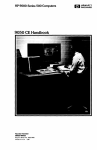
Service Handbook
HP 9000 Series 300 Computers
Model 319C+
HP Part Number 98564-90039
FliOW
HEWLETT
~~ PACKARD
Hewlett-Packard Company
3404 East Harmony Road, Fort Collins, Colorado 80525
NOTICE
The Information contained in this document is subject to change without notice.
HEWLETT-PACKARD MAKES NO WARRANTY OF ANY KIND WITH REGARD TO THIS MANUAL. INCLUDING.
BUT NOT LIMITED TO. THE IMPLIED WARRANTIES OF MERCHANTABILITY AND FITNESS FOR A PARTICULAR PURPOSE. Hewlett-Packard shall not be liable for errors contained herein or direct. indirect. special.
incidental or consequential damages in connection with the furnishing. performance. or use of this material.
WARRANTY
A copy of the specific warranty terms applicable to your Hewlett-Packard product and replacement parts can be
obtained from your local Sales and Service Office.
Copyright
© Hewlett-Packard Company 1987
ThiS document contains Information which is protected by coPYright. All rights are reserved. Reproduction. adaptation.
or translation without prior written premission is prohibited. except as allowed under the copyright laws
Restricted Rights Legend
Use. dupllCatlOf1 or disclosure by the U.S. Government Department of Defense IS SUbJect to restrictions as set forth
paragraph (bX3Xii) of the Rights in Technical Data and Software clause in FAR 52.227-7013.
In
COPYrlght:0 AT&T. Inc. 1980.1984
Copyright © The Regents of the University of California 1979. 1980. 1983
This software and documentation is based in part on the Fourth Berkeley Software Distribution under license from the
Regents of the University of California.
ii
Printing History
New editions of this manual will incorporate all material updated since
the previous edition. Update packages may be issued between editions
and contain replacement and additional pages to be merged into the
manual by the user. Each updated page will be indicated by a revision
date at the bottom of the page. A vertical bar in the margin indicates
the changes on each page. Note that pages which are rearranged due to
changes on a previous page are not considered revised.
The manual printing date and part number indicate its current edition.
The printing date changes when a new edition is printed. (Minor
corrections and updates which are incorporated at reprint do not cause
the date to change.) The manual part number changes when extensive
technical changes are incorporated.
November 1987 ... Edition 1
Printing History
iii
Notices
Radio Frequency Interference Statements
FCC Statement
Federal Communications Commission
Radio Frequency Interference Statement
(U.S.A. Only)
The Federal Communications Commission (in Subpart J of Part 15, Docket
20780) has specified that the following notice be brought to the attention
of the users of this product.
Warning: This equipment generates, uses, and can radiate radio frequency energy and if not installed and used in accordance with the instructions manual, may cause interference to radio communications. It
has been tested and found to comply with the limits for a Class A computing device pursuant to Subpart J of Part 15 of FCC rules, which are
designed to provide reasonable protection against such interference when
operated in a commercial environment. Operation of this equipment in a
residential area is likely to cause interference in which case the user at his
own expense will be required to take whatever measures may be required
to correct the interference.
VCCI Statement (Japan Only)
-c rllJ 15R till t~ C' 0) '~ j1!z ~~ '6- ~jJ it. ~ B B1 c L t::. Ur f~ ~ fEfJ M<: [(t '1Y ~ j1!z ~ti! '& t'=l
thh ~ ~ (V eel) 1il; i1f Ie ~ ~ L L to
fff
iv
-:J
L.
Notices
ft'-tttl!t~
it::. (t f-
O)~f£
VJ
i -g
L
t::.ttl!t&-C{~ffi
1~
W. itl]
0
-g 6 C, 7:; ~,
T v t:.:;
Manufacturer's Declaration (Germany Only)
Herstellerbescheinigung
Hiermit wird bescheinigt, daB dieses Gerat in Ubereinstimmung mit
den Bestimmungen der Postverfiigung 1046/84 funkentstort ist. Der
Deutschen Bundespost wurde das Inverkehrbringen dieses Geratcs
angezeigt und die Berechtigung zur Uberpriifung der Serie auf Einhaltung der Bestimmungen eingeraumt.
Safety Considerations
WARNINGs, CAUTIONs, and Notes
Warnings, cautions and notes are used throughout this document to
alert the user to conditions of importance. They are used as follows:
• WARNINGS contain information which, if not observed, could
result in injury to personnel or loss of life.
• CAUTIONS contain information which, if not observed, could
result in damage to or destruction of equipment.
• Notes contain information that will assist you in accomplishing the
job.
Notices
v
Examples:
WARNING
The power supply presents a hazard to personnel.
Extreme care must be taken when connecting
voltmeter probes to the test points. De-energize
the product by turning it off and removing its
power cord before connecting or removing test
probes.
I CAUTION I
The printed circuit assemblies in this product
are susceptible to damage by electro-static discharge. Extreme care must be taken when handling printed circuit assemblies. Use an Antistatic Workstation while handling printed circuit
assemblies.
Note
Hewlett-Packard supports repair of this product
only to the assembly level. The fault is diagnosed
to the assembly that is causing the problem. That
assembly is then replaced with a new or rebuilt
one.
vi
Notices
Service Information Locator
On the next page is a Service Information Locator. First, find the
information to reference in the left-hand column. Next, move to the
right to a chapter number. Last, move up to the abbreviated manual
title that has the information documented.
Chapter identifiers in the Locator use the following codes:
Chapter Number:
Numbers, such as 2. Inclusive chapters,
such as 4-6.
Appendices:
Letters, such as A for Appendix A.
Entire Manual:
All
Varies:
* (Check
Table of Contents or Index.)
Manuals identified in this locator are abbreviated by their initials:
SIM
Service Information Manual
SHB
Service Handbook
CRM
Configuration Reference Manual
TTM
Series 300 Test Tools Manual
SPM
Site Preparation Manual
IRM
Installation Reference Manual
PIN
Product Installation Note
TDS
Technical Data Sheet/Price List
vii
Service Information Locator
Service Information
Assembly replacement
Block diagrams
Booting Operating Systems
SIM
SHB
CRM TTM SPM
1, 2
4
2
Configurations
1
3
1, 5
5
Electrical requirements
1
1
3, A
Environmental req uir('ments
1
2
4, A
Functional descriptions
3
1, 2, 3
All
Monitors
People who can help
All
4
*
*
2, 3
HP -HIL device tests
I/O Bus architecture
TDS
9
1, 5
Installation
PIN
2
Computer tests
(;S/80 tests
IRM
2
2
All
All
All
3
All
A
1
All
1.3
1
1
*
Service Information Locator (cont.)
SIM
SHB
Options/ Accessories
1.3
3
Ordering spare parts
6
8
Part numbprs
6
8
All
Periphprals
1
3
All
Preventive maintpnancp
SPM
All
1
All
All
Product numbers
1
1.3
All
A
Reference material
7
10
*
4. 5
5
1
11
Site preparation
5
Systems
1
3
Trouhleshooting
5
4
31 4
41 5
Thrn-on
TDS
All
All
*
All
All
All
All
All
All
All
*
1.2
2
1,5
System Functional Tests
PIN
*
1
Service notes
IRM
2
Product information
Self-tests
~.
CRM TTM
Service Information
All
11 3
All
All
2
x
Table of Contents
Chapter 1: Product Information
Introduction. . . . . . . . . . . . . . . . . . . . . . . . . . . . . . . . . . . . . . . . . . . ..
Features ............................................... ,
Hewlett-Packard Support .................................
Repair Philosophy ...................................
HP Repair Serv ices .................................. ,
Repair by Customers ................................ ,
Operating Systems Support .......................... ,
Serial Numbers . . . . . . . . . . . . . . . . . . . . . . . . . . . . . . . . . . . . ..
Technical Data ..........................................
Physical ........................................... ,
Processor Board .................................... ,
I/O Bus ............ , ..... , .......... ',' ............ ,
Video-SCSI/HP-IB Board. . . . . . . . . . . . . . . . . . . . . . . . . . ..
Shipping Information ................... , . . . . . . . . . . ..
HP-HIL Accessories. . . . . . . . . . . . . . . . . . . . . . . . . . . . . . . ..
Monitors. . . . . . . . . . . . . . . . . . . . . . . . . . . . . . . . . . . . . . . . . ..
System Software . . . . . . . . . . . . . . . . . . . . . . . . . . . . . . . . . . ..
Standard Tools ....................................... "
SPU /System Tests . . . . . . . . . . . . . . . . . . . . . . . . . . . . . . . . ..
Chapter 2: Technical Information/Installation/PM
Technical Information ...................................
Electrical ..........................................
Environmental. . . . . . . . . . . . . . . . . . . . . . . . . . . . . . . . . . . . ..
Electromagnetic Interference .........................
Regulatory Requirements. . . . . . . . . . . . . . . . .. . . . . . . . . ..
Physical ....... . . . . . . . . . . . . . . . . . . . . . . . . . . . . . . . . . . ..
Shipping Information. . . . . . . . . . . . . . . . . . . . . . . . . . . . . . ..
HP-HIL and Video Accessories .......................
Preventive Maintenance. . . . . . . . . . . . . . . . . . . . . . . . . . . . . . . . ..
Table of Contents
1
1
3
3
4
5
5
7
8
8
8
9
10
10
11
12
12
13
14
15
15
16
16
16
16
17
17
19
xi
Chapter 3: Configuration
Bundled Systems .......................................
Supported Configurations. . . . . . . . . . . . . . . . . . . . . . . . . . . . . . ..
SPU Configuration Switches. . . . . . . . . . . . . . . . . . . . . . . . . . . . ..
HP -HIL Accessories . . . . . . . . . . . . . . . . . . . . . . . . . . . . . . . ..
21
21
22
23
Chapter 4: Troubleshooting
Analytic Troubleshooting ................................
Initial Troubleshooting Flowchart. . . . . . . . . . . . . . . . . . . . . . . ..
Dead Unit Troubleshooting Flowchart. . . . . . . . . . . . . . . . . . . ..
Live Unit Troubleshooting Flowchart. . . . . . . . . . . . . . . . . . . . ..
Power Supply Technical Information. . . . . . . . . . . . . . . . . . . . . ..
Voltage Indicators. . . . . . . . . . . . . . . . . . . . . . . . . . . . . . . . . ..
General Failure Indications. . . . . . . . . . . . . . . . . . . . . . . . . ..
Boot ROM Error Codes .............................
Remote SPU Analysis . . . . . . . . . . . . . . . . . . . . . . . . . . . . . . . . . ..
Boot ROM State Codes. . . . . . . . . . . . . . . . . . . . . . . . . . . . . . . . ..
25
26
27
28
29
29
30
31
32
33
Chapter 5: SPU Tests
Test Tools ............................................. 35
Package Contents . . . . . . . . . . . . . . . . . . . . . . . . . . . . . . . . . .. 35
Chapter 6: Adjustments
Chapter 7: Peripherals
Supported Peripherals List . . . . . . . . . . . . . . . . . . . . . . . . . . . . . .. 39
Chapter 8: Parts Lists
Parts Information. . . . . . . . . . . . . . . . . . . . . . . . . . . . . . . . . . . . . ..
Introduction. . . . . . . . . . . . . . . . . . . . . . . . . . . . . . . . . . . . . . ..
Exchange Parts . . . . . . . . . . . . . . . . . . . . . . . . . . . . . . . . . . . ..
Part Number Lists. . . . . . . . . . . . . . . . . . . . . . . . . . . . . . . . . . . . ..
Static-Free Bags. . . . . . . . . . . . . . . . . . . . . . . . . . . . . . . . . . ..
SPU Electrical Parts ................................
HP -HIL Devices ....................................
SPU Case Parts ....................................
SPU Parts List. . . . . . . . . . . . . . . . . . . . . . . . . . . . . . . . . . . ..
xii
Table of Contents
41
41
42
42
42
42
44
45
46
Chapter 9: Diagrams
SPU Block Diagram .................................... ,
Power Supply ..........................................
Processor / Add-On RAM Board .......................... ,
Video-HS HP-IB/SCSI Board ............................
Video Circuit. . . . . . . . . . . . . . . . . . . . . . . . . . . . . . . . . . . . . ..
SCSI Circuit .......................................
High-Speed HP-IB Circuit ...........................
49
50
51
52
52
53
54
Chapter 10: Reference
Hardware Support Documentation ........................ 55
Chapter 11: Service Notes
Notes ........................................... , ..... , 58
Table of Contents
xiii
xiv
1
Product Information
Introduction
Information in this handbook refers to the HP 9000 Series 300 tvlodel
319c+ Workstation's SPU.
Features
Table 1-1. Model 319C+ Workstation Features
Product Number
Description
System Processing Unit
MC68020 CPU at 16.67 MHz
MC68881 Floating Point Co-CPU, 16.67 MHz
MC68851 Memory Management Unit, 16.67 MHz
4, 8, 12, or 16 Mbytes of RAM
SPU Interfaces
IEEE-488 HP-IB Interface
RS-232C Serial Interface
IEEE 802.3/Ethernet LAN Interface with
ThinMAU Two channel DMA Controller
RGB High-Res Color Video Output
HP-HIL
Optional Small Computer Systems Interface
(SCSI)
Optional High-Speed HP-IB
Monitor
HP 98785A High-Resolution Color, 1024 by 768
resolution.
Keyboard
HP 46021A (HP-HIL)
Operating Systems
HP-UX and NS/ ARPA on 3.5-inch disc or
O.25-inch tape.
Product Information
1
Table 1-2. Model 319C+ Workstation Options
Product Number
Options Available
Opt. 010
Opt. 011
Opt. 022
Opt. 045
Opt. 060
Opt. 084
Opt. 108
Opt. 112
Opt. 116
Opt. 305
Opt. 306
Opt. 751
2
Product Information
Description
Add High-Speed HP-IB Interface
Add SCSI Interface (Available early 1988)
HP-UX on 0.25-inch Tape
HP-UX on 3.5-inch Disc
Add HP 46060A Mouse
Add HP 46084A ID Module
8 Mbytes of RAM (Replace 4 Mbyte RAM with
8 Mbyte RAM)
12 Mbytes of RAM (Replace 4 Mbyte RAM with
12 Mbyte RAM)
16 Mbytes (Replace 4 Mbyte RAM with 16 Mbyte
RAM)
Add HP 50952B Opt. 022 NS-ARPA on 0.25-inch
Tape
Add HP 50952B Opt. 045 NS-ARPA on 3.25-inch
Disc
Replace HP 98785A 16-inch Monitor with
HP 98751A 19-inch Monitor
Hewlett-Packard Support
Support services and policies mentioned in this section are subject to
change. Please consult your local Hewlett-Packard Sales and Service
Office for the current support policies.
Repair Philosophy
Field Repair Philosophy for this SPU is assembly, or board level. This
means that when a failure occurs, the problem is diagnosed to the
assembly having the failed part. That assembly is then replaced.
Replacement assemblies are available through local HP Sales and Service
Offices.
Some assemblies may be exchanged for rebuilt ones. Other assemblies
are only available as new ones. Refer to Chapter 6, or the Service
Handbook, Chapter 8, for information on replacement parts.
Schematics
In support of the repair philosophy, this manual contains information to
the assembly level. Schematics are not available for these products.
Supported Configurations
Only workstations with Hewlett-Packard approved parts, accessories,
peripherals, operating systems and application programs are supported
by Hewlett-Packard. Any workstation with other than HP approved
hardware or software connected or installed must have the non-HP
approved hardware and software removed by the customer before OnSite repair is accomplished.
Product Information
3
HP Repair Services
There are many hardware support options available, from utilizing
customer's maintenance groups to buying full support from the local
HP Sales Office. Please contact your local Hewlett-Packard Sales and
Service Office for complete information.
Hewlett-Packard provides repair services for Model 319C+ Workstation
SPU's in four ways:
• Priority On-Site Service
• Next Day On-Site Service
• Standard System Maintenance Service
• Scheduled On-Site Service
More information is available in the HP 9000 Series 300 Pricing Information Sheet Contact your local HP Sales and Service for complete
information on these services. Each is briefly described below.
Priority On-Site Service
If the workstation applications call for a high level of availability, Priority
On-Site Service offers a four-hour coverage. This service is especially
valuable if the customer does not stock spare equipment at his site.
Next Day On-Site Service
For Next Day On-Site Service, an HP Customer Engineer goes to the
customers site on the next day (Monday through Friday, exluding HP
Holidays) after the service call, troubleshoots, and repairs the hardware
to the assembly level. The defective assembly is replaced with a new or
rebuilt assembly. This service is available through a service contract or
a time-and-materials basis.
Standard System Maintenance Service
HP will travel to a customer's site and provide all labor, parts, and
materials deemed necessary to keep systems in good operating condition.
Inc luded are
• Corrective and Preventive Maintenance.
• Engineering improvements.
• Site environmental survey.
HP will utilize a customer-owned diagnostic modem used with the HP
Support Link to test equipment covered the contract.
4
Product Information
Scheduled On-Site Service
Provides the lowest on-site support costs for a minimum of twenty-five
HP workstation products. HP will make weekly visits to a single central
site which the customer specifies.
Repair by Customers
In addition; customers may obtain service training courses and spare
parts to do their own repair. Contact your nearest HP Sales and Service
Office for information concerning service training, special tools and test
equipment, and spare parts.
Operating Systems Support
HP-UX Installation Services
A set of modular services that provide expert installation of hardware,
operating system, and selected HP DesignCenter applications is available. They allow users to make productive use of their system in the
shortest possible time. Services include:
• Interconnection of system hardware.
• Formatting discs.
• Loading and configuration of the HP-UX Operating System.
• Loading applications.
• Verification of system operation.
• Review of the system for its System Administrator.
Refer to the HP 9000 Series 300 HP- UX Installation Services Technical
Data (5954-9695) for details and complete information.
Primary Support
There are numerous operating system support options:
• Account Management Support (AMS) provides a local SE, onsite assistance, one Response Center caller and one alternate for
telephone assistance, and a Software Materials Subscription.
• Response Center Support (RCS) provides one Response Center
caller and one alternate for telephone assistance, and Software
Materials Subscription.
• Software Materials Subscription (SMS) provides software and manual updates, Software Status Bulletins, and HP communicator
magazine. Updates to ROM-based systems are not provided.
Product Information
5
Support For An Additional System
The following options support an additional syst('m:
• Additional System Coverage extends AMS or RCS coverage on the
operating system to one additional system under the same system
manager. All support is delivered through the central system.
• Extended Materials Support extends SMS by providing the right
to make one copy of all central system materials for use on one
additional system.
• Additional Response Center Caller provides one additional caller
and one alternate for access to the HP Response Center
• Manual Update Service (MUS) provides one copy of updates to
software reference manuals.
• Software Notification Service (SNS) provides issues of the HP
Communicator and Software Status Bulletin.
6
Product Information
Serial Numbers
Serial No.
XXXX A 01234
' - - v - ' "'-v-' ~
Location: On the outside of the rear panel.
Description:
~._
t
5-digit unique identifying number.
Country of Origin Code.
Product Code, decoded as:
First 2 digits + 60 = Last 2 digits of year
product was introduced or significantly
changed.
Last 2 digits = number of week in year
product was introduced or significantly
changed.
Product Information
7
Technical Data
Physical
Dimensions
Height
104 mm (4.1 inches)
Width
325 mm (12.8 inches)
Length
444 mm (17.5 inches)
Weight
4.55 kg (10 pounds) maximum
Vibration Standard
Meets Class B requirements
Processor Board
CPU
Type
Motorola MC68020
Clock Frequency
16.67 Mhz
Internal Architecture
32-bit data and address registers
Address range
4 Gbytes virtual mapped to
4 Gbytes physical
Data bus
32-bit synchronous to:
4 or 8 Mbytes On-board RAM and
4 or 8 Mbytes Add-On RAM
Floating point Coprocessor
Type
Motorola MC68881
Clock Frequency
16.67 Mhz
MMU
8
Type
Motorola MC68851
Clock Frequency
16.67 Mhz
Product Information
LAN Interface
Media
ThinLAN coax cable (RG 58U)
Protocols
IEEE 802.3 Ethernet
Data Rate
10 Mhits /sec
1
Parallel Interface
Type
HP-IB (IEEE 488)
Data Rate
350 Kbyte/sec
Number of connected
devices
15 per interface devices supported
Serial Interface
Type
RS-232C standard
Capacitor-backed
Real-Time Clock
Rebolutioll
10 milliseconds
Accuracy
±5 seconds/day
24 hours
Clock life
Memory
Size
4 Mbytes or 8 Mbytes
Type
Byte parity error-checking
Average cycle time
300 nsec
I/O Bus
Width
32 bits address; 16 bits data
Bus bandwidth
6 Mb/sec
Product Information
9
Video-SCSI/HP-IB Board
Video Interface
High-Resolution Color
Shipping Information
The shipping container for each SPU includes the Localization Kit,
which includes power cords, keyboard cable, HP-HIL cable, Safety and
Regulatory Information, and Installation Picture Card.
Shipping Weight
9.1 kg (20 pounds)
Container Dimensions
Width - 533 mm (21 inches)
Length - 584 mm (23 inches)
Depth - 292 mm (11.5 inches
Cube - 0.085 m 3 (3.21 feet 3 )
10
Product Information
HP-HIL Accessories
Table 1-3. HP-HIL Devices
Product
Number
Product Name/Description
35723A
Touchscreen Bezel
46021A
ITF keyboard
46060A
2-button Mouse
46083A
HP-HIL Knob
46084A
ID Module
46085A
Control Dial Module
46086A
32-button Control Box
46087A
ANSI A/ISO A4-size digitizer
46088A
ANSI A/ISO A3-size digitizer
46089A
4-button cursor for 46087 A and 46088A
46094A
Quadrature port
46095A
3-button mouse for 46094A
Product Information
11
Monitors
The HP 98551A and 98785A High-Resolution Monochrome Monitor is
supported with Model 319C+ Workstations.
System Software
Table 1-4. HP-UX Operating System
Product
Number
Description
HP98515A
HP-UX 5.5 AXE (Single-user)
HP98595A
HP-UX 5.5 AXE (Multi-user)
HP98517A
HP-UX 5.2 Pgm. Env. (Single-user)
HP 98597A
HP-UX 5.2 Pgm. Env. (Multi-user)
HP 98518A
HP-UX 5.2 FORTRAN 77 Compiler
(Single-user)
HP 98598A
HP-UX 5.2 FORTRAN 77 Compiler
(Multi-user)
HP97055A
HP-UX 5.2 Ada Compiler (Multi-user)
HP97066A
HP-UX 5.2 Technical BASIC
HP98678A
Development Env. for Common LISP
HP98679A
Execution License for Common LISP
HP 50952B
NS-ARPA Services/300 Ntwk. Software
HP 79232U
PROLOG
HP 98674A
Star base Display List
HP 36590A
HP-UX SNA 3270 for Series 300
HP 36591A
HP-UX Gateway /SNA 3270 for each
S('ries 300
Table 1-5. BASIC Language Systems for Service Use Only
Product
Number
HP98613D
12
Description
RAM BASIC 5.1 Language System
Product Information
Standard Tools
The following tools are needed to service the SPU:
Table 1-6. Standard Tools
Part/Product
Number
9300-0933
Description
Anti-static workstation
T -10 Torx® screwdriver
8720-0001
3/16-inch nutdriver
8720-1219
5mm nut driver
9/32-inch nut driver
8720-0007
1/2-inch nutdriver
HP 347613
Digital Multimeter
5/8-inch open-end wrench
Product Information
13
SPU/System Tests
Table 1-7. Series 200/300 Test Tools
Part No.
09800-12300
Description
Series 200/300 Test Tools, eight 3.5-inch discs
Table 1-8. Series 200/300 Test Tools 3.5-inch Discs
Part No.
Contents
09800-90001
Series 200/300 Test Tools Manual
09800-10336
Series 200 Computer Tests Disc Rev. 1.1
98561-10334
Series 300 Computer Tests Disc Rev. 2.0
Series 200/300 System Functional Tests Discs:
09800-00334
SFTO Disc Rev. 1.2
09800-11335
SFT1 Disc Rev. 1.2
09800-11336
SFT2 Disc Rev. 1.2
09800-11337
SFT3 Disc Rev. 1.2
09800-11338
SFT4 Disc Rev. 1.2
09800-11304
14
CS/80 Exerciser Disc Rev. 3.1
Product Information
Technical Information/
Installation/PM
2
Technical Information
Note
Technical information listed below should not be
interpreted as product specifications.
Official
product specifications are listed in the HP 9000
Series 300 Hardware Technical Data and Pricing
Sheet.
Electrical
Line voltage/frequency
120 V ac @ 48-66 Hz
240 V ac @ 48-66 Hz
Line transient spike immunity
(1 nsec rise, 800 nsec duration)
1 KV dc
Power Consumption
110 Watts maximum
Current Requirements
1. 9 A
1.0 A
@
@
120 V ac
240 V ac
Maximum Heat Dissipation
380 BTU/hr
112 Kcal/hr
Capacitor Back-up
Real-Time Clock on Processor
Board
Technical Information/ Installation/PM
15
Environmental
Operating temperature
o - 55°
Operating humidity
5 - 80% relative
Operating altitude
4 572 metres (15 000 feet)
C (32 - 104° F)
Electromagnetic Interference
Standards met
FCC Class A
VCCI Class 1
VDE Class B, VDE 1046/84
Regulatory Requirements
Standards met
UL 478, 5th Edition
CSA 220-M1986
IEC 380, 2nd Edition; 435, 2nd
Edition
Physical
Dimensions
Height
104 mm (4.1 inches)
Width
325 mm (12.8 inches)
Length
444 mm (17.5 inches)
Weight
4.55 kg (10 pounds) maximum
Vibration Standard
Meets Class B requirements
16
Technical Information/ Installation/PM
Shipping Information
The shipping container for each SPU includes the Localization Kit,
which includes power cords, keyboard cable, HP-HIL cable, Safety and
Regulatory Information, and Installation Picture Card.
Shipping \Veight
9.1 kg (20 pUUlltb)
Container Dimensions
Width - 533 mm (21 inches)
Length - 584 mm (23 inches)
Depth - 292 mm (11.5 inches
Cube - 0.085 m 3 (3.21 feet 3 )
HP-HIL and Video Accessories
Table 2-1 lists HP-HIL and video accessories compatible with the Model
319C+ Workstations. For a complete list, consult the HP 9000 Series
300 Model 319C+ Workstation's Hardware Price List.
Technical Information/ Installation/PM
17
Table 2-1. HP-HIL Devices
Product
Number Product Name/Description
18
46021A
ITF keyboard
46060A
2-button Mouse
46083A
HP-HIL Knob
46084A
ID Module
46085A
Control Dial Module
46086A
32-button Control Box
46087A
ANSI A/ISO A4-size digitizer
46088A
ANSI A/ISO A3-size digitizer
46089A
4-button cursor for 46087 A and 46088A
46094A
Quadrature port
46095A
3-button mouse for 46094A
Technical Information/ Installation/PM
Preventive Maintenance
There is no preventive maintenance requirement for the Model 318M
Workstation's SPU.
Technical Information/ Installation/PM
19
20
Technical Information/ Installation/PM
Configuration
3
Bundled Systems
Refer to the current HP 9000 Series 300 Price List to determine what
HP products are bundled into this systems.
Supported Configurations
Rrfer to the Series 800 Configuration Reference Manual (98561-90020)
for the current hardware and software products that are supported.
Configuration
21
SPU Configuration Switches
Table 3-1. Configuration Switches
MEN
REM
Switch
Label
MEN
Function /How 1t'8 Used
Modem Enable
1=
o=
REM
Modem lines enabled (Shipped setting)
Modem lines disabled
Remote Terminal Enable
1 = Remote Mode
Local Mode (Shipped setting)
o=
LAN
Local/Remote
o=
Local Mode (Shipped setting)
1 = Remote Mode
SC
Internal HP-IB System Controller
1 = System Controller (Shipped setting)
Not System Controller
o=
22
Configuration
HP-HIL Accessories
HP-HIL devices are limited to a total of 1 A of current and seven addresses per SPU.
Table 3-2. HP-HIL Devices and Current/Power Requirements
Product
Number
Device Name
mA
Watts
HP 46021A
ITF Keyboard
100
1.2
HP 46060A
HP Mouse
200
2.4
HP 46080A
Extension Module
25
0.3
HP 46081A
3 Metre Ext.
25
0.3
HP 46082A/B
15/30 Metre Extension l
50
0.6
HP 46083A
Rotary Control Knob
110
1.32
HP 46084A
ID Module
60
0.72
HP 46085A
Control Dials
350
4.2
HP 46086A
80
0.96
2
200
2.4
2
Button Box
HP 46087A
2
HP 46088A
2
"A" -Size Digitizer
200
2.4
HP 46094A
Quadrature Port Device 3
80
1.2
HP 46095A
Three-Button Mouse
80
0.96
HP 92916A
Barcode Reader
100
1.2
Notes:
1
2
3
"B" -Size Digitizer
Extension cables have two boxes, each draws 25 rnA.
Includes HP 46089A 4-Button Cursor.
Port devices require 80 rnA; devices attached cannot
exceed 120 rnA.
Configuration
23
24
Configuration
4
Troubleshooting
Analytic Troubleshooting
Troubleshooting SPU s is the process of getting answers to these five
questions:
• What exactly is wrong, or what are the bad symptoms?
• Where are the bad symptoms appearing?
• When do the bad symptoms occur?
• How bad is the problem or to what extent does it occur?
• What actually caused the problem in the first place?
Getting the answers to these questions usually makes the troubleshooting process much more effective and less costly. \Vhen a failure in a
workstation occurs. remember these questions and get the answers to
each of them.
After you have all answers possible, decide what's the most probable
cause of the problem. Sometimes you'll arrive at several choices for a
cause. For each choice, qualify it against the answers to the questions
above. The most probable cause is the one that logically justifies the
correct answers to these questions.
Troubleshooting
25
Initial Troubleshooting Flowchart
Check Fan
& LEOs
26
Goto Dead
Goto live
Unit Procedure
Unit Procedure
Troubleshooting
Dead Unit Troubleshooting Flowchart
Check Voltage
Select Switch
and Line Voltage
>----I~ Replace:
Power
>--_~
Goto
Live
Unit
Supply
Replace:
Processor
Board
Procedure
Troubleshooting
27
Live Unit Troubleshooting Flowchart
Replace Indicated
Failed Assembly
28
Troubleshooting
Power Supply Technical Information
Make sure that the SPU is properly grounded. It requires a three-wire
power cahle and the power supply retaining/grounding screw must be
installed. Also, make sure that the power supply access door is properly
installed.
Voltage
Tolerance
+5 V de
4.89 to 5.25 V de
+12 V
11.86 to 12.72 V de
-12 V
-11.86 to -12.72 V de
Voltage Indicators
Voltage
-12 V de
+5 V
+12 V de
Indication
(none)
Self-test LED lit at turn-on.
Fan Running
Voltage Reference
Test Points
Figure 4-1. Power Supply Test Points
Troubleshooting
29
General Failure Indications
Table 4-1. Self- Test LED General Failure Indications
Failure Indications
via Upper Two LEDs
LED Pattern
General Description of Failure
State Indication Only
ooss ssss,
Where ss ssss Indicates State of
Power-up
Required Device Missing or
DTACK Failure
o.dd dddd,
where dd dddd Indicates Device
Failing Device
.odd dddd.
where dd dddd Indicates Device
Special Codes
••••••••
(Special Case Highest Priority Codes) LEDs Never Accessed
(or Unused Code)
0 •••••••
LEDs Failed to DTACK
0000 0 . 0 .
Timer on processor board has failed
or is missing.
State or Device Codes
Via Lower 6 LEDs
LED Pattern
General Description of Failure
Miscellaneous (Highest Priority)
xxoo ffff
Where ffff indicates Failure (xs are
don't-care bits)
Internal Peripheral Failure
(Medium
Priority)
xxo. pppp
Where pppp is Peripheral Number
I/O Failure
(Lowest Priority)
xx.s ssss
Where s ssss is Select Code
30
Troubleshooting
Boot ROM Error Codes
Table 4-2. Boot ROM LED Error Codes
LEDs
Probable Cause
Replace or Do
0000 0000
No Failure Detected
0000 0 . 0 .
CPU Timer Missing
Processor Board
0.00 0.00
Top RAM Failed
Check RAM Configuration.
0 •••••••
LEDs failed to acknowledge
Processor Board
.000 000.
CPU Failed
Processor Board
.000 00 • •
Boot ROM Failed Checksum
Processor Board
• 000 0.00
Top RAM Failed
Processor Board .
.000 . 0 0 .
RAM Failure
Add-On RAM Board.
Processor Board.
• 000 . 0 . 0
Insufficient RAM
Processor Board .
• 0 • • 00.0
Keyboard Controller Failed
Processor Board .
• 00. 0.00
HP-IB Failed
Processor Board .
• 00 • • 000
DMA Failed
Processor Board .
• 00 • • • 00
Bit Map Font Failed
Video Board .
.00 •
Bit Map Failed
Video Board
••0.
I-oxx xxxx I/O at xx xxxx Failed
I/O at Select Code xx xxxx.
•••• ••••
Check -12 V dc .
If okay,
replace Processor Board. Otherwise, replace
Power Supply.
LEDs Never Accessed
Troubleshooting
31
Remote SPU Analysis
The SPU and monitor allows remote analysis of problems by means of
the beeper. To test the SPU remotely, follow this procedure:
1. Establish a telephone connection with someone at the location of
the completely installed workstation.
2. Have them hold the receiver near the speaker output. The speaker
is located in most monitors, or in the speaker module.
3. Now have them turn the SPU on.
4. The SPU will go through its self-test and report problems as a
series of beeps. These beeps correlate with the above error codes.
5. The beeper annunciates the seven least significant bits. A high
beep indicates a one and a low beep indicates a zero.
For example, suppose that on power-up a SPU emits three low beeps,
a high beep, two low beeps and a high beep. This will be of the form
000 eooe, where 0 represents a low beep, e represents a high beep and
x represents an unbeeped high or low. Referring to the table of Boot
ROM Error Codes shows a RAM Failure as the probable cause.
32
Thoubleshooting
Boot ROM State Codes
Table 4-3. LED State Codes In Numerical Order
LEDs
Test Activity
0000 0000
No failure
0000 000.
LED ripple (all on, then off in sequence from MSB)
0000 00.0
Resetting I/O
0000 0 0 . .
Checksumming Boot ROM (or LED ripple)
0000 0.00
Testing top RAM (or maybe the Boot ROM checksum failed)
0000 0 • • 0
Searching for boot extension ROMs
0000
Starting test vector list (or LED ripple)
0...
0000 .000
Preloading RAM
0000 . 0 0 .
Testing RAM
0000 • • • •
LED ripple
000. 00.0
Testing keyboard circuit (or an interrupt line is stuck)
000. 0 • • 0
Testing processor HP-IB
000 • • 000
Testing DMA
000 •
• • 0.
oo.x xxxx
I
Checksumming ID /INIT ROM
Testing I/O at select code x xxxx
Troubleshooting
33
34 Thoubleshooting
5
SPU Tests
Test Tools
Package Contents
The combined Series 200/300Test Tools software package is provided on
both 3.5-inch discs and O.25-inch tape as shown below:
Part N umbe Description
09800-12300
Series 200/300 Test Tools, eight 3.5-inch discs
Discs in the 3.5-inch disc package are listed below.
Part N umbe Contents
09800-90001
Series 200/300 Test Tools Manual
09800-10336
Series 200 Computer Tests Disc Rev. 1.1
98561-10334
Series 300 Computer Tests Disc Rev. 2.0
Series 200/300 System Functional Tests Discs:
09800-11334
SFTO Disc Rev. 1.2
09800-11335
SFT1 Disc Rev. 1.2
09800-11336
SFT2 Disc Rev. 1.2
09800-11337
SFT3 Disc Rev. 1.2
09800-11338
SFT4 Disc Rev. 1.2
09800-11304
CS/80 Exerciser Disc Rev. 3.1
SPU Tests
35
36
SPU Tests
Adjustments
6
There are no adjustments in the SPU. For adjustments to other products
in the workstation, refer to the product's Service Manual or Handbook.
Adjustments
37
38
Adjustments
Peripherals
7
Supported Peripherals List
Due to constant changes of supported peripherals 1 this information is
published separately in the Series 300 Configuration Reference Manual
(98561-90020).
The HP 9000 Series 300 Technical Data Sheet and Hardware Pricing
List also has supported peripheral information.
Peripherals
39
40 Peripherals
8
Parts Lists
Parts Information
Introduction
Field replaceable parts are listed in this chapter for the SPU. Components, such as ICs, are not available for field repair.
Parts are available direct from:
Corporate Parts Center
333 Logue A venue
Mountain View, California 94042 USA
Telephone: (415) 968-9200
Parts may be ordered through your local HP Sales and Service Office. To
help get parts as soon as possible, please write the address and telephone
number of your local HP Office in the spaces below.
Name:
Address:
City, State ZIP:
Telephone:
Parts Lists
41
Exchange Parts
Exchange parts are available for some items at a reduced cost. When an
exchange part is ordered, your account will be charged for a new part.
Customers have 15 days to return the failed part to receive credit for
the difference between a new and exchange part.
Please return failed exchange parts to your local HP Sales and Service
Office as soon as possible. Place them in anti-static bags (see Parts List
for part numbers) and package them securely in a sturdy container. It's
a good idea to save the containers and static-free bags you receive parts
in and use them to ship parts in.
Part Number Lists
The parts listed in this section apply to only the SPU used in the Model
319C+ Workstation, unless noted otherwise. Various accessories and
HP-HIL devices are also listed.
Static-Free Bags
Part No.
Description
9222-0980
9-inch by 15-inch cushioned pouch.
Notes
SPU Electrical Parts
Miscellaneous Electrical Parts
Part No.
Description
98564-61602
Power distribution cable
98564-62701
Line filter
09125-68500
Fan
42
Parts Lists
Notes
Printed Circuit Boards
Exchange
Part No.
New
Part No.
Description
0950-1894
Power supply
98564-69508 98564-66508
Processor board w / 4 Mbyte
98564-69.509 98564-66509
Processor board w /8 Mbyte
98564-69520 98564-66520
Add-on RAM board, 4 Mbyte
98564-69521 98564-66521
Add-on RAM board, 8 Mbyte
98564-69570 98564-66570
Video board
98564-69571 98564-66571
Video board w /SCSI
98564-69572 98564-66572
Video board w IRS RP-IB
Notes
Parts Lists
43
HP-HIL Devices
Exchange
Part No.
New
Part No.
Description
46021-60201
ASCII Keyboard
46020-60001
Keyboard Cable
HP 46060A
HP Mouse
46081-61601
2.4-metre extension cable
46082-61601
Short audio cable
46082-61602
30-metre audio extension cable
46082-61604
15-metre remote cable
46082-61605
15-metre video cable
46083-61601
Short audio cable
46083-67901
Switch cap assembly
HP 46085A
Control dials
46085-85000
0403-0430
QEDS-7099
Overlay
Molded foot
RPG assembly
5041-2416
RPG knob
HP 46084A
ID module
HP 46086A
Button box
HP 46087A
"A" size digitizer
HP 46088A
"B" size digitizer
HP 46094A
Quadrature port device
HP 46095A
3-button mouse
HP 92916A
Bar code reader
44 Parts Lists
Notes
! 1~
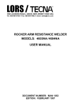
F"19ure 8-1. SPU Exploded V·lew
SPU Parts List
Ref. Part Number Description
1
98564-67002
Power Supply
2a
98564-66510
Processor board / 4 Mb
2b
98564-66511
Processor board / 8 Mb
3a
98564-66520
4 Mb Add-On RAM board
3b
98564-66521
8 Mb Add-On RAM board
4a
98564-66570
Video board
4b
98564-66571
Video-SCSI board
4c
98564-66572
Video-HS HP -IB board
,
Fan
5
5180-1336
6
98564-62701
Line filter
7
98564-61602
Power distribution cable
8
98564-61602
ON/OFF cable
9a
5001-9025
9b
35751-40001
10
98561-84002
* Case
* Front Panel
* Label, name
11
09121-48303
Molded foot
12
0403-0427
* Bumper
13a
5001-9027
Rear panel (standard)
13b
5001-9026
Rear panel for SCSI
13c
5001-9029
14
98564-84002
Label, 120/240 volt
15
98564-84001
Label, model/serial
Rear panel for HS HP-IB
Parts identified by an asterisk (*) are required when either the case or
front panel need replaced. The front panel cannot be removed from the
case.
46 Parts Lists
SPU Parts List (cont.)
Ref. lPart Number Description
16
3050-0604
Flat washer
17
0160-6777
Capacitor /washer
18
3050-1291
Shoulder washer
19
5001-9030
Tongue bracket
20
5041-2424
ON/OFF keycap
21
5001-9028
Power supply plate
22
5041-2426
Power supply insulator
23
5041-2423
Rail
24
0380-1947
Spacer, 33 mm
25
0505-0082
Hex nut
26
0380-0643
HP-IB jack screw
27
1251-7812
RS-232 jack screw
28
2190-0407
Lock washer, internal tooth
29
2190-0054
Lock washer, internal tooth
30
2190-0409
Lock washer, internal tooth
31
0624-0525
10-24 self-tapping screw
32
2940-0256
Double hex nut
33
0515-1919
Screw / washer assembly
34
0624-0706
Torx screw, 0.94-in. long
35
0624-0707
Torx screw, 1.75-in. long
36
0515-1851
Screw, M3 by 6 mm
37
0515-0372
Torx screw, M3
38
2200-0104
Flat-head screw
Parts Lists
47
48
Part~
Lists
9
Diagrams
SPU Block Diagram
l
Power
Supply
-
Processor
Board
4/8 Mbyte
RAM
~J
~
CPU
l~
LAN
-1
r""'
~
~~
RS232
f~
~y
HP-IB
~~
...
,.
HPIL
l•
...
,.
.
.. J
"
"
'"
~
"
4~
~
...
,.
..,
4/8 Mbyte Add-On
RAM
Board
Video Board
~ R
~ G
~
B
~
I/O
High-Speed HP-IB
or
SCSI
Diagrams
49
~
=
115/230 Jumper
INPUT
tj
I
~.
oq
'"1
~
S
CJ:J
I
SYSTEM
INTERFACE
BOARD
I
I
Bridge rectifier
@230
Voltage doubler
@115
en
AC Input
120/240 Vae
L
SWITCH
c:
~
OUTPUT
CONTROL_
12 Isolated
Rectifier & Filter
+5 Output
Rectifier & Filter
+12 Output
Rectifier & Filter
-12 Output
Rectifier & Filter
-12
"C
"C
~
."
on
(I)
fA
fA
_~~1.
-r- BA
' ,Lf'6"
r
BO
\1)
7'----
»
c.
c.
I
o:J
F~:~
~____
o
~
XO
:D
_ 010
Control
»
3:
OJ
o
m
c.
...
_.
<
c:< c.
(1)
0
(I)
0
=;-
0I
c
en
(")
FRAME
BUFFER
16
.r
I
2-L
/
RUG
--
BARC
0
/
STATUS
REGISTER
DIO
BUS
INTERFACE
~lOCAl
010
(16 BIT)
tr
16
-
r---
16,
.r
BARC
1
16
/
GLAD
BUS
INTERFACE
f--f---
16,
-,
-
-
BARC
ROM
GLAD BUS
(16 81T)
2
G-
PLANE 0
PLANE
::;:
-a
"
4
4Wf=
PLANE
3--.-J
PLANE 5
PHANTOM
PLANE
4L
"
-OJ
I
1~
21
PLANE
::J:
4/
PLANE
::J:
~
<
is
fT1
0
4
IRIS
~
c
~
"
0
-I
C
-I
(J)
...........
en
en
-
0
OJ
0
m
...
c.
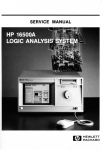
SCSI Circuit
~
I
DID
Diagrams
SCSI
Bus
53
-
1 INTERRUPT
1
"""-
~
.... BUF
-L
100-07
-
..
~
I
SOO-S07
J~
REGISTERS
S08-S015
I~
.. J
I
L_
I~
-
-
~~
"
FIFO
FIFO
.~
J~
"
CO
CO
Co
:t
o
~'
-~.
BUF
(')
c:
-
L..
1-
SOOO-S007
"
"
.t
BACKPLANE TO
FIFO CONTROL
DMA Control
;::;:
"
I
4~
..PIJ-~
BUF
•
"
S008-S0015
,~
"""-
rABI
J~
BUF
BUF
.. JI
•
,r
DIO
BUS
~
I.. J -BUF
""D
.!..
OJ
D8-015
L.t -
:::r
I
en
}*
-L.L
BUF
to'
-
NON-DMA
CONTROL
r
~ J~
"""-
:t
I ..
.."'1J BUF
-
"
ABI TO
FIFO CONTROL
r~
HPIB BUS
10
Reference
Hardware Support Documentation
lPart Number Manual Title
09000-90041
HP 9000 Series 200/300/500 Site Preparation Manual
98561-90020
Series 300 Configuration Reference Manual
98562-90005
HP 9000 Series 200/300 Test Tools Manual
98564-90030
HP 9000 Series 300 Model 319C+ Workstation's SPU Service
Information Manual
98564-90039
HP 9000 Series 300 Model 319C+ Workstation's SPU Service
Handbook
98564-90099
HP 9000 Series 300 Model 319C+Workstation's SPU SelfPaced Hardware Training Guide
Reference
55
56 Reference
Service Notes
11
Service Notes
57
Notes
58
Service Notes
Flin-
HEWLETT
~~ PACKARD
HP Part Number
98564-90039
Microfiche No. 98564-99039
Requires Binder No. 9282-0683
Printed in U.S.A.
11/87
98564-90639
For Internal Use Only