1
SERVICE MANUAL
Flin-
HEWLETT
~~ PACKARD
HP 16500A
LOGIC ANALYSIS
MAINFRAME
SYSTEM
Service Manual
r/i~ HEWLETT
~~ PACKARD
r/iO'l HEWLETT
a!~ PACKARD
SERVICE MANUAL
HP MODEL 16500A
LOGIC ANALYSIS SYSTEM
MAINFRAME
SERIAL NUMBERS
This manual applies directly to instruments
with serial numbers prefixed 2650A.
For additional information about serial numbers see
INSTRUMENTS COVERED BY THIS MANUAL
in Section I.
©
COPYRIGHT HEWLETT-PACKARD COMPANY/COLORADO SPRINGS DIVISION 1987
1900 GARDEN OF THE GODS ROAD, COLORADO SPRINGS, COLORADO, U.S.A.
ALL RIGHTS RESERVED
Printed in U.S.A. September 1987
Manual Part Number 16500-90901
Microfiche Part Number 16500-90801
CERTIFICATION
Hewlett-Packard Company certifies that this product met its published specifications at the time of
_ shipment from the factory. Hewlett-Packard further certifies that its calibration measurements are
traceable to the United States National Bureau of Standards, to the extent allowed by the Bureau's
calibration facility, and to the calibration facilities of other International Standards Organization
members.
WARRANTY
This Hewlett-Packard product is warranted against defects in material and workmanship for a
period of one year from date of shipment. During the warranty period, Hewlett-Packard Company
will, at its option, either repair or replace products which prove to be defective.
For warranty service or repair, this product must be returned to a service facility deSignated by HP.
Buyer shall prepay shipping charges to HP and HP shall pay shipping charges to return the
product to Buyer. However, Buyer shall pay all shipping charges, duties, and taxes for products
returned to HP from another country.
HP warrants that its software and firmware deSignated by HP for use with an instrument will
execute its programming instructions when properly installed on that instrument. HP does not
warrant that the operation of the instrument or software, or firmware will be uninterrupted or error
free.
LIMITATION OF WARRANTY
The foregoing warranty shall' not apply to defects resulting from improper or inadequate
maintenance by Buyer, buyer-supplied -software or interfacing, unauthorized modification or
misuse, operation outside the environmental specifications for the product, or improper site
preparation or maintenance.
NO OTHER WARRANTY IS EXPRESSED OR IMPLIED. HP SPECIFICALLY DISCLAIMS THE
IMPLIED WARRANTIES OF MERCHANTABILITY AND FITNESS FOR A PARTICULAR PURPOSE.
EXCLUSIVE REMEDIES
THE REMEDIES PROVIDED HEREIN ARE BUYER'S SOLE AND EXCLUSIVE REMEDIES. HP
SHALL NOT BE LIABLE FOR ANY DIRECT, INDIRECT, SPECIAL, INCIDENTAL, OR
CONSEQUENTIAL DAMAGES, WHETHER BASED ON CONTRACT, TORT, OR ANY OTHER LEGAL
THEORY.
ASSISTANCE
Product maintenance agreements and other customer assistance agreements are available for
Hewlett-Packard products.
For any aSSistance, 'contact your nearest Hewlett-Packard Sales and Service Office. Addresses are
provided at the back of this manual.
CWA584
SAFETY CONSIDERATIONS
GENERAL - This Is a Safety Class I Instrument (provided
o Do not Install substitute parts or perform any unauthorized
with terminal for protective earthing).
modification to the Instrument.
OPERATION - BEFORE APPLYING POWER verify that the
o Adjustments described In the manual are performed with
power 'transformer primary Is matched to the available line
voltage, the correct fuse Is Installed, and Safety Precautions
power supplied to the Instrument while protective covers
are removed. Energy available at many pOints may, If
are taken (see the following warnings). In addition, note the
contacted, result in personal injury.
Instrument's external markings which are described under
"Safety Symbols."
o Any adjustment, maintenance, and repair of the opened
Instrument under voltage should be avoided as much as
I
WARNING
I
pOSSible, and when Inevitable, should be carried out only by
a skilled person who Is aware of the hazard Involved.
o Servicing instructions are for use by service-trained
personnel. To avoid dangerous electriC shock, do not
perform any servicing unless qualified to do so.
o BEFORE
SWITCHING
ON
THE
o Capacitors Inside the Instrument may stili be charged even
If the Instrument has been disconnected' from Its source of
supply.
INSTRUMENT,
the
protective earth terminal of the Instrument must be
connected to the protective conductor of the' (mains)
powercord.
SAFETY SYMBOLS
The mains plug shall only be Inserted In a
socket outlet provided with a protective earth contact. The
Instruction manual symbol. The product will be
marked with this symbol when it Is necessary for
protective action must not be negated by the use of an
extension
cord
(power
cable)
without
a
protective
conductor (grounding). Grounding one conductor of a two-
the user to refer to the instruction manual In order
to protect against damage to the product.
conductor outlet Is not sufficient protection.
o If
this
instrument
Is
to
be
energized
via
~
an
Indicates hazardous voltages.
auto-transformer (for voltage reduction) make sure the
common terminal is connected to the earth terminal of the
--L
power source.
Earth terminal (sometimes used in manual to
Indicate circuit common connected to grounded
chassis).
o Any Interruption of the protective (grounding) conductor
(inside or outside the Instrument) or disconnecting the
protective earth terminal will cause a potential shock
hazard that could result In personal InJury.
o Whenever It Is likely that the protection has been Impaired,
the Instrument must' be made Inoperative and be secured
against any unintended operation.
I
WARNING
I
The WARNING sign denotes a hazard. It
calls attention to a procedure, practice,
or
the
like,
which,
If
not
correctly
performed or adhered to, could result In personal InJury. Do
not proceed beyond a WARNING sign until the Indicated
conditions are fully understood and met.
o Only fuses with the required rated current, voltage, and
specified type (normal blow, time delay, etc.) should be
used.
Do not use repaired fuses or short circuited
fuseholders. To do so could cause a shock or fire hazard.
":::":::::::~~;:~! The CAUTION sign denotes a hazard. It
I~i
calls attention to an operating procedure,
practice,
or
the
like,
which,
If
not
correctly performed or adhered to, could result In damage to
o Do not operate the Instrument In the presence of flammable
or destruction of part or all of the product. Do not proceed
gasses or fumes. Operation of any electrical Instrument In
beyond a CAUTION sign until the Indicated conditions are
such an environment constitutes a definite safety hazard.
fully understood or met.
5010984
HP 16500A-Table of Contents
TABLE OF CONTENTS
Page
Section
I. GENERAL INFORMATION ....................................................................... 1-1
1-1.
1-2.
1-3.
1-4.
1-5.
1-6.
1-7.
1-8.
II.
Introduction ........................................................................... 2-1
Safety Considerations ................................................................. 2-1
Initial Inspection ....................................................................... 2-1
Operating Disc Installation ..................... '....................................... 2-1
Power Requirements ................................................................. 2-1
Line Voltage Selection ................................................................ 2-1
'Power Cable ............................... ~ .......................................... 2-2
User Interface ......................................................................... 2-4
The Touchscreen ..................................................................... 2-4
The Front Panel Knob ................................................................ 2-4
The HP Mouse ........................................................................ 2-4
HP-IB Interfacing ..................................................................... 2-5
HP-IB Address Selection ............................................................. 2-5
HP-IB Address Codes ................................................................ 2-7
HP-IB Interface Functions ............................................................ 2-8
RS-232-C Interface ................................................................... 2-8
Baud Rate Selection ............................................................... 2-10
Degaussing the Display ............................................................ 2-12
Operating Environment ............................................................ 2-12
Storage and Shipment ............................................................. 2-12
Packaging .......................................................................... 2-12
Tagging for Service ................................ ~ ................................. 2-12
PERFORMANCE TESTS ....................................................................... 3-1
3-1.
i"V
1-1
1-1
1-1
1-2
1-2
1-2
1-2
1-6
INSTALLATION '................................................................................. 2-1
2-1.
2-2.
2-3.
2-4.
2-5.
2-6.
2-7.
2-8.
2-9.
2-10.
2-11.
2-12.
2-13.
2-14.
2-15.
2-16.
2-17.
2-18.
2-19.
2-20.
2-21.
2-22.
III.
Introduction ...........................................................................
Instruments Covered By Manual .....................................................
Safety Considerations .................................................................
Product Description .. '..................................................................
Accessories Supplied ....... '..........................................................
Accessories Available .................................................................
Operating Characteristics .............................................................
Recommended Test Equipment ......................................................
Introduction ........................................................................... 3-1
HP 16500A-Table of Contents
TABLE OF CONTENTS
IV.
ADJUSTMENTS
4-1.
4-2.
4-3.
4-4.
4-5.
V
REPLACEABLE PARTS
5-1.
5-2.
5-3.
5-4.
5-5.
5-6.
VI.
Introduction ........................................................................... 4-1
Degaussing the Display ............................................................... 4-1
Safety Considerations ................................................................. 4-1
Adjustment Test Patterns .............................................................. 4-2
Color Module Adjustment ............................................................. 4-7
Introduction ...........................................................................
Abbreviations ...................................................... ·....................
Replaceable Parts List ................................................................
Exchange Assemblies ................................................................
Ordering Information ..................................................................
Direct Mail Order Syst.em .............................................................
5-1
5-1.
5-1
5-1
5-1
5-2
SERVICE
6-1.
6-2.
6-3.
6-4.
6-5.
6-6.
6-7.
6-8.
6-9.
6-10.
6-11.
6-12.
6-13.
6-14.
6-15.
6-16.
6-17.
6-18.
Introduction ........................................................................... 6-1
Safety Considerations ................................................................. 6-1
Service Test Equipment Required .................................................... 6-1
Theory of Operation .................................................................. 6-1
System Overview ...................................................................... 6-3
Microprocessor Board Theory ........................................................ 6-5
Power Up Tests ....................................................................... 6-6
Mainframe Test System ............................................................... 6-7
Troubleshooting. . . . . . . . . . . . . . . . . . . . . . . . . . . . . . . . . . . . . . . . . . . . . . . . . . . . . . . . . . . . . . . . . . . .. 6-16
Repair............................................................................... 6-29
Power Supply Replacement ......................... . . . . . . . . . . . . . . . . . . . . . . . . . . . . . .. 6-30
Microprocessor Board Replacement
6-33
Mother Board Replacement ........................................................ 6-35
Front Panel Board Replacement ................................................... 6-37
Display Module Replacement ...................................................... 6-39
Front Disc Drive replacement ...................................................... 6-44
Rear Disc Drive Replacement ...................................................... 6-45
Cooling Fan Replacement ..................... . . . . . . . . . . . . . . . . . . . . . . . . . . . . . . . . . . .. 6-46
II II II II ... II .. II II II II II II II II .... II II II II " '
v
HP 16500A-Table of Contents
LIST OF TABLES
Table
1-1 .
1-2.
Title
Page
Operating Characteristics ............................................................ 1-3
Recommended Test Equipment ..................................................... 1-6
2-1. HP-IB Address Settings .............................................................. 2-7
2-2. Model 16500A HP-IB Functions ..................................................... 2-8
2-3. . RS-232-C Signal Definitions ......................................................... 2-9
5-1 .
5-2.
6-1 .
Reference Designators and Abbreviations ........................................... 5-3
Replaceable Parts .................................................................... 5-5
Replaceable Assemblies ........................................................... 6-29
LIST OF ILLUSTRATIONS
Figure Title
vi
Page
1-1.
HP Model 16500A Dimensional Detail ............................................... 1-5
2-1 .
2-2.
2-3.
2-4.
2-5.
2-6.
2-7.
2-8.
2-9.
2-10.
Line Voltage Selection ............................................................... 2-2
Power Cord Configurations .......................................................... 2-3
HP 16500A User Interface Devices .................................................. 2-4
HP-IB Interface Connector ........................................................... 2-5
System Configuration Menu ......................................................... 2-6
HP-IB Configuration Menu ........................................................... 2-6
HP-IB Configuration with Keypad .................................................... 2-7
System Configuration with optional Mouse ....................................... 2-10
RS-232-C Configuration Menu .................................................... 2-10
Baud Rate Pop-up Menu .......................................................... 2-11
4-1 .
System Configuration Menu ......................................................... 4-2
4-2.
Accessing the System .........•.•.................................................... 4-2
4-3.
4-4.
4-5.
4-6.
4-7. .
Loading the Test System ............................................................ 4-3
Test System Configuration ................................. ; ......................... 4-3
Selecting Mainframe Test Menu ..................................................... 4-4
Mainframe Test Menu ................................................................ 4-4
Selecting the Test Patterns .......................................................... 4-5
HP 16500A-Table of Contents
LIST OF ILLUSTRATIONS
4-8. Exiting the Mainframe Test System ................................................. 4-5
4-9. Exiting the Test System .............................................................. 4-6
4-10. System Configuration ............................................................... 4-6
4-11. CRT Module Adjustment Flow Chart ................................................ 4-8
4-12. PIN AMP Adjustment ................................................................ 4-9
4-13. Bottom Rail Removal ............................................................... 4-10
4-14. PIN PHASE Adjustment ........................................................... 4-10
4-15. Purity Magnet Centering .......................................................... 4-13
4-16. Purity Magnet Adjustment Raster ................................................. 4-14
4-17. Landing and Purity Adjustment ................................................... 4-15
4-18. Static Convergence ................................................................ 4-16
4-19. Y BOW Adjustment ................................................................ 4-17
4-20. Y BOW CROSS Adjustment ....................................................... 4-17
4-21. V.STAT TOP Adjustment .......................................................... 4-18
4-22. V.STAT BOTTOM Adjustment ..................................................... 4-18
4-23. H.AMP Adjustment ................................................................ 4-19
4-24. H.TILT Adjustment ............... : ................................................. 4-19
5-1 .
5-2.
Electrical Assembly Identification .................................................... 5-4
Chassis Parts Identification .......................................................... 5-6
6-1 .
6-2.
6-3.
6-4.
6-5.
6-6.
6-7.
6-8.
6-9.
6-10.
6-11 .
6-12.
6-13.
6-14.
6-15.
6-16.
6-17.
6-18.
6-19.
6-20.
6-21.
System Overview ..................................................................... 6-2
Microprocessor Block Diagram ...................................................... 6-4
System Configuration ................................................................ 6-7
Accessing the Test System ....... "................................................... 6-7
Loading the Test System Software .................................................. 6-8
Test System Configuration ........................................................... 6-8
Mainframe Test Menu ................................................................ 6-8
All System Test ....................................................................... 6-9
Selecting the Color Display Test Patterns ......................................... 6-10
Mainframe Test Menu ............................................................. 6-11
ROM Test Screen ................................................................. 6-11
Choosing the Single or Repetitive Mode.. .. .. .... .. .. .. .. .. .. .. . .. .. .. .... .. .. ... 6-12
ROM Test in the Repetitive Mode ................................................. 6-12
Exiting the Mainframe Test System ............................................... 6-13
Exiting Mainframe Configuaration ................................................ 6-13
Reloading the Mainframe System ................................................. 6-14
HP 16500A Power-up Test ........................................................ 6-16
Main Troubleshooting Flow Chart ................................................. 6-17
Color Module Troubleshooting Flow Chart ....................................... 6-18
Checking for Color module Signals ............................................... 6-20
System Boot Troubleshooting Flow Chart ........................................ 6-21
vii
HP 16500A-Table of Contents
LIST OF ILLUSTRATIONS
6-22. Power Supply Troubleshooting Flow Chart ......................................
6-23. Power Supply Check .............................................................
6-24. Checking Power supply Resistance to Ground ..................................
6-25. HIL Troubleshooting Flow Chart .................................................
6-26. Disc Drive Troubleshooting Flow Chart ..........................................
6-27. RS-232-C Troubleshooting Flow Chart ..... .. .. .. .. .. .. .. .. .. . .. .. . .. .. .. . .. .. ...
6-28. Intermodule Troubleshooting Flow Chart ........................................
6-29. Replaceable Assembly Identification .............................................
6-30. Power Supply Rear Panel ........................................................
6-31 . Power Supply Mounting Scews and Display Power Cable ......................
6-32. Power Supply Connector Alignment .............................................
6-33. Power Supply Rail Alignment ....................................................
6-34. Microprocessor Cable Location ..................................................
6-35. Microprocessor Board Mounting Screws ........................................
6-36. Power Supply and Microprocessor Hardware Identification .....................
6-37. Microprocessor Board Removal ..................................................
6-38. Mother Board Removal ...........................................................
6-39. Front Panel Cable Removal ......................................................
6-40. Front Panel Mounting Screws Identification .....................................
6-41 . Front Panel Board Hardware Indentification .....................................
6-42. Front Panel Mounting Screws Identification .....................................
6-43. Module Bracket Mounting Hardware.............................................
6-44. Center Board Guide Hardware ...................................................
6-45. Display Module Rear Mounting Bracket .........................................
6-46. Display Module Rear Mounting Bracket Assembly ..............................
6-47. Final Positioning of Front Panel and Display Module ............................
6-48. Front Disc Removal ...............................................................
6-49. Front Disc Drive Replacement....................................................
6-50. . Rear Disc Drive Removal .........................................................
6-51. Side Fan Mounting Screws and Power Cable Removal .........................
6-52. Rear Fan Removal ................................................................
viii
6-22
6-23
6-24
6-25
6-26
6-27
6-28
6-29
6-30
6-31
6-31
6-32
6-33
6-33
6-35
6-36
6-36
6-37
6-37
6-38
6-39
6-40
6-40
6-41
6-42
6-43
6-44
6-44
6-45
6-46
6-47
TABLE OF CONTENTS
GENERAL INFORMATION
1-1.
1-2.
1-3.
1~4.
1-5.
1-6.
1-7.
1-8.
Introduction ............................................................................
Instruments Covered by Manual ......................................................
Safety Considerations ..................................................... . . . . . . . . . . . ..
Product Description ....................................................................
Accessories Supplied ..................................................................
Accessories Available ..................................................................
Operating Characteristics ..............................................................
Recommended Test Equipment .......................................................
1-1
1-1
1-1
1-2
1-2
1-2
1-2
1-6
HP 16500A - General Information
SECTION I
GENERAL INFORMATION
1-1. INTRODUCTION
This Service Manual explains how to test, adjust, and service the Hewlett-Packard 16500A
Logic Analysis System mainframe. This
manual is divided into six sections as follows:
I - General Information
2 - Installation
3 - Performance Tests
4 - Adjustments
5 - Replaceable Parts
6 - Service
Information for operating. programming, and
interfacing the Model 16500A is contained in
the HP 16500A Operating and Programming
manual set supplied with each instrument.
The General Information Section includes a
description of the HP Model 16500A, its
specifications, options, available accessories,
and recommended test equipment for maintaining the instrument.
Also listed on the title page of this manual is a
Microfiche part number. This number can be
used to order 4 X 6 inch microfilm transparencies of the manual. Each microfiche contains
up to 96 photo-duplicates of the manual
pages. The microfiche package also includes
the latest Manual Changes supplement and
pertinent Service Notes.
1-2. INSTRUMENTS COVERED BY
MANUAL
The instrument serial number is on the rear
panel. Hewlett- Packard uses a two-part serial
number consisting of a four-digit prefix and a
five-digit suffix separated by a letter
(OOOOAOOOOO). The prefix is the same for all
identical instruments and changes only when a
modification is made that affects parts compatibility. The suffix is assigned and is different for each instrument. This manual applies directly to instruments with the serial
prefix shown on the title page.
An instrument manufactured after the printing
of this manual may have a serial number prefix
that is not listed on the title page. This unlisted serial prefix indicates the instrument is different from those described in this .manual.
The manual for this newer instrument is accompanied by a Manual Changes supplement.
This supplement contains "change information" that explains how to adapt the manual to
the newer instrument.
In addition to change information, the supplement may contain information for correcting
errors in the manual. To keep this manual as
current and accurate as pOSSible,
Hewlett-Packard recommends that you
periodically request the latest Manual Changes
supplement. The supplement for this manual
is identified with the manual print date and
.part number, both of which appear on the
manual title page. Complimentary copies of
the supplement are available from
Hewlett-Packard.
1-3. SAFETY CONSIDERATIONS
Shipped with this manual are service manuals
for each module ordered with the the HP
16500A. To complete the service documentation for your system, unpack the module service manuals and place them in the 3-ring
binder of this manual.
This product is a Safety Class 1 instrument
(provided with a protective earth terminal).
Review the instrument and manual for safety
markings and instructions before operating.
Specific warnings, cautions, and instructions
are placed wherever applicable throughout the
1-1
HP 16500A - General Information
manual. These precautions must be observed
during all phases of operation, service, and
repair of the instrument. Failure to comply
with these precautions or with specific warnings elsewhere in this manual violates safety
standards of design, manufacture, and intended use of this instrument.
Hewlett-Packard assumes no liability for the
customers failure to comply with these safety
requirements.
1-6. ACCESSORIES AVAILABLE
The following optional accessories are available for the HP Model 16500A:
•
•
•
•
•
HP 46060A Mouse
HP 16510A State/Timing Analyzer
HP 16515A/16516A 1 GHz Timing Analyzer
HP 16520A/16521 A Pattern Generator
HP 16530A/16531 A Digitizing Oscilloscope
•
•
•
HP 2225A ThinkJet Printer (HP-IB Interface)
HP 10833A/B/C/O HP-I B Cable
HP 2225D ThinkJet Printer (RS-232-C
Interface)
RS-232-C DTE to DTE cable for connecting
the HP 16500A to printers and controllers.
HP Part No. 13242-60010.
RS-232-C OTE to DCE cable for connecting
the HP 16500A to modems and data
switche. HP Part No. 13242-60001.
1-4. PRODUCT DESCRIPTION
The HP Model 16500A is the mainframe of the
logic analysis system. It is of modular structure
using plug - in cards with a wide range of data
aquisition and stimulus cards. This allows the
user to configure the system with only the
necessary modules for a particular application.
•
•
Some of the key features of the HP 16500A
are:
• Modular mainframe with five card slots.
.• Nine inch color monitor.
•
•
•
•
HP 1008A Testmobile (Option 006)
HP 74240A/B CAE Software
Rackmount Kit HP Part No. 5061-9679
Service Data Suuplement
• The touchscreen user interface.
• Dual 3.5 inch floppy disc drives.
1-7. OPERATING CHARACTERISTICS
• Intermodule triggering and time correlation
of aquired data.
• HP-IB and RS-232-C Interfaces for
hardcopy output to a printer or controller
interface.
1-5. ACCESSORIES SUPPLIED
The following accessories are supplied with
the HP Model 16500A:
1 Power cord
1 Operating and Reference manual set
1 Service manual
Rear panel filler panels depending on how
many modules are ordered with HP Model
16500A
1 Operating System Disc
1 Blank Disc
1-2
Table 1-1 is a listing of the instrument's operating characteristics. These are not specifications, but are typical operating characteristics
included as additional information for the user.
HP 16500A - General Information
Table 1-1. HP Model 16500A Operating Characteristics
BUILT-IN DISC DRIVES
File Types: System software; configuration (contains instrument configuration, data,
pOinter to inverse assembler file); inverse assembler; auto-configuration, calibration.
Autoload Designation: A predefined configuration file can be loaded at po.wer-up.
Disc Operations: Store, load, copy, duplicate disc, pack disc, rename, purge, and format
disc.
PROGRAMMABILITY
Instrument settings and operating modes, including automatic measurements, may be
remotely programmed via RS-232-C or HP-IB (IEEE-488).
HARDCOPY OUTPUT
Printers Supported: HP ThinkJet, HP QuietJet, HP LaserJet, HP PaintJet, Epson and
Epson-compatible (e. g. Epson FX-BO) via RS-232-C or HP-IB.
RS-232-C Configurations: Protocols: XON/XOFF, Hardware; Data bits: 7, 8; Stop bits: 1,
1 1/2, 2; Parity: none, odd, or even; Baud rates: 110, 300, 600, 1200, 2400, 4800, 9600,
19200.
INPUT/OUTPUT REAR PANEL BNCs:
Input BNC:
Labled Port-in. Input signal must drive four LS TTL loads, active high.
Output BNC: Labled Port-out. Output signal is active high, TTL output level: high
into 50 Ohms, low ~ OAV into 50 Ohms.
~
2V
1-3
HP 16500A - General Information
Table 1-1. HP Model 16500A Operating Characteristics (Continued)
OPERATING ENVIRONMENT
Temperature:
Instrument: O°C to 55°C (+32°F to 131°F).
Disc Media: 10 0 C to 50° C (+50° F to 122° F).
Probes and Cables: 0 0 C to 65° C (+32° F to 149 0 F).
Humidity:
Instrument: up to 95% relative humidity at 40°C (104° F)
Disc media: 8% to 80% relative humidity at 40° C (104°).
Altitude:
Up to 4600 m (15 000 tt).
Vibration:
Operating: Random vibration 5-500Hz, 10 minutes per axis, - 0.3g (rms).
Non-operating: Random vibration 5-500Hz, 10 minutes per axis, - 2.4 g (rms); and
swept sine resonant search, 5-500Hz, 0.75g (O-peak), 5 minute dwell @ 4
resonances per axis.
WEIGHT
Net: 18.1 kg (40 Ibs) + 0.7 kg (1.6Ibs) x number of optional cards installed.
Shipping: 25.9 kg (57 Ibs) + 3.6 kg (8 Ibs) x number of optional cards installed.
POWER REQUIREMENTS:
115V/230V, 48 to 66Hz, 475W max
DIMENSIONS:
Refer to figure 1-1 for dimensional detail.
1-4
HP 16500A - Genera I Information
482.6 (19.0")
425.7 (16.76")
i
. Dimensl
'onal Detail
Figure 1-1. Hp Mode I 16500A
.
1-5
HP 16500A - General Information
1-8. RECOMMENDED TEST
EQUIPMENT
Equipment required to test and maintain the
HP Model 16500A is listed in table 1-2.
Other equipment may be substituted if it meets
or exceeds the critical specifications listed in
the table.
Table 1-2. Recommended Test Equipment.
INSTRUMENT
TYPE
RECOMMENDED
MODEL
OSCILLOSCOPE
HP MODEL 54201 A
WITH
PROBES
RS 232-C LOOP
BACK
CONNECTOR
HP PART NO.
01650-63202
VOLTMETER
HP MODEL 346SA
REQUIRED CHARACTERISTICS
REQUIRED
FOR
BANDWIDTH 100MHz
T
T
3 1/2 DIGIT RESOLUTION
A = Adjustments, P = Performance Verification, T = Troubleshooting
1-6
T
TABLE OF CONTENTS
INSTALLATION
2-1 .
2-2.
2-3.
2-4.
2-5.
2-6.
2-7.
2-8.
2-9.
2-10.
2-11.
2-12.
2-13.
2-14.
2-15.
2-16.
2-17.
2-18.
2-19.
2-20.
2-21.
2-22.
Introduction. . . . . . . . . . . . . . . . . . . . . . . . . . . . . . . . . . . . . . . . . . . . . . . . . . . . . . . . . . . . . . . . . . . . . . . . . . .. 2-1
Safety Considerations ................................................................... 2-1
Initial Inspection ........................................................................ 2-1
Operating Disc Installation ............................................................. 2-1
Power Requirements .................................................................. 2-1
Line Voltage Selection ................................................................. 2-1
Power Cable ........................................................................... 2-2
User Interface .......................................................................... 2-4
The Touchscreen ...................................................................... 2-4
The Front Panel Knob ................................................................. 2-4
The HP Mouse ......................................................................... 2-4
HP-IB Interfacing ...................................................................... 2-5
HP-IB Address Selection ............................................................... 2-5
HP-IB Address Codes ................................................................. 2-7
HP-IB Interface Functions ............................................................. 2-8
RS-232-C Interface .................................................................... 2-8
Baud Rate Selection ................................................................. 2-10
Degaussing the Display .............................................................. 2-12
Operating Environment .............................................................. 2-12
Storage and Shipment ............................................................... 2-12
Packaging ............................................................................ 2-12
Tagging for Service ................................................................... 2-12
HP 16500A - Installation
SECTION II
INSTALLATION
2-1. INTRODUCTION
This section explains how to install the H P
Model 16500A Logic Analysis System, inspect
it, prepare it for use, store and ship it.
2-2. SAFETY CONSIDERATIONS
The safety symbols used with Hewlett-Packard
instruments are illustrated in the front matter
of this manual. WARNING and CAUTION symbols and instructions should be reviewed
before operating the instrument. These warnings and cautions must be followed for your
own protection and to avoid damage to the
instrument.
2-4. OPERATING DISC INSTALLATION
The instrument is shipped with yellow protective discs in each disc drive. Before applying
power to the mainframe, remove the protective
discs from the front and rear disc drives and
install the operating disc in one of the disc
drives. Reinstall the protective discs whenever
the instrument is transported.
2-5. POWER REQUIREMENTS
The HP Model 16500A requires a power
source of either 115 Vac or 230 Vac, 48 to 66
Hz, 475 W maximum.
.
2-3. INITIAL INSPECTION
Inspect the shipping container for damage. If
the shipping container or cushioning material
is damaged, it should be kept until the contents of the shipment have been checked for
completeness and the instrument has been
checked mechanically and electrically. The
contents of the shipment should be as listed in
the "Accessories Supplied" paragraph in
Section I. If the contents are incomplete, or if
there is mechanical damage, notify the nearest
Hewlett-Packard office. If the shipping container is damaged, or the cushioning material
shows signs of stress, notify the carrier as well
as the Hewlett-Packard office. Keep the shipping material for carrier's inspection. The HP
office will arrange for repair or replacement at
HP option without waiting for claim settlement.
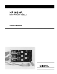
2-6. LINE VOLTAGE SELECTION
The instrument may be damaged if the
Line Voltage Select switch is not properly set.
When shipped from the factory, the Line
Select switch is set and an appropiate fuse is
installed for operating the instrument in the
country of destination.
2-1
HP 16500A - Installation
2-7. POWER CABLE
To operate the instrument from a power
source other than the one set at the factory,
proceed as follows:
1. Turn front panel switch to STBY and rear
panel power switch to OFF. Remove power
cord from instrument.
2. Replace the main fuse with a 5A/250 V for
230 V operation, or a 10 A/250 V fuse for
115 V operation.
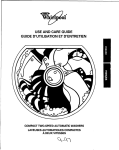
This instrument is equipped with a three-wire
power cable. When connected to an appropriate AC power outlet, this cable grounds
the instrument cabinet. The type of power
cable plug shipped with the instrument
depends on the country of destination. See
figure 2-2 for option numbers of available
power cables and plug configurations.
3. Set rear panel Line Select switch for desired
line voltage.
4. Reconnect power cord, turn on rear panel
power switch and continue normal
operation.
ft..'Sf WI1H SAME TYPE' Ar1D HATING
fOR P1WI'lH COOLING INSTAll Htt.rR PflNH
11(i~.O()
CAUTION; POW~R
"""" "-",", "'VA.A>
@ r~~;:;;;g:
Figure 2-1. Line Voltage Selection
2-2
.. 40('0"}
1',
OPEN CARll Stors
OFF TO C~ANGf MOO'J ..
~1~lEECT
rs
•
@
DEGAUSS
•
HP 16500A - Installation
Figure 2-2. Power Cord Configurations
PLUG TYPE
OPT
900
250vq
OPT
250V
901~
OPT
250V
902~
OPT"
903
125V
OPT"
904
250V
~
~
"~
~
OPT
905
OPT
906
()
CABLE
PART NO.
PLUG DESCRIPTION
LENGTH
IN/eM
COLOR
COUNTRY
8120-1351
8120-1703
Straight 'BS1363A
90°
90/228
90/228
Gray
Mint Gray
United Kingdom,
Cyprus,
Nigeria,
Zimbabwe,
Singapore
8120-1369
8120-0696
Straight 'NZSS198/ASC
90 0
79/200
87/221
Gray
Mint Gray
Australia,
New Zealand
8120·1689
8120·1692
8120-2857
Straight 'CEE7·Y11
90 0
Straight (Shielded)
79/200
79/200
79/200
Mint Gray
Mint Gray
Coco Brown
East and West Europe,
Saudi Arabia,
So. Africa,
India (Unpolarized
in many nations)
8120·1378
8120·1521
8120·1992
Straight 'NEMA5·15P
90 0
Straight (Medical)
UL544
90/228
90/228
96/244
Jade Gray
Jade Gray
Black
United States,
Canada,
Mexico,
Philippines,
Taiwan,
8120·0698
Straight 'NEMA6-15P
90/228
Black
United States,
Canada
8120·1396
8120·1625
CEE22·V1
(System Cabinet Use)
250V
30176
96/244
Jade Gray
For interconnecting
system components and
peripherals.
United States and
Canada only
8120·2104
8120-2296
Straight 'SEV1 011
1959·24507
Type 12
90°
79/200
79/200
Mint Gray
Mint Gray
Switzerland
8120-2956
8120-2957
Straight 'DHCK107
90°
79/200
79/200
Mint Gray
Mint Gray
Denmark
8120-4600
8120-4211
Straight SABS164
90°
79/200
79/200
Jade Gray
Republic of South Africa
India
8120-4753
8120-4754
Straight Miti
90°
90/230
90/230
Dark Gray
Japan
0
250V
~
250V
~
OPT
220V
912~
OPT
917
250V
OPT
918
100V
t
~ ~
~
, Part number shown for plug is industry identifier for plug only. Number shown for cable is HP Part Number for complete cable including plug .
• 'These cords are included in the CSA certification approval of the equipment.
E
Earth Ground
Line
L
N = Neutral
=
=
2-3
HP 16500A - Installation
2-8. USER INTERFACE
Three devices may be used to interface with
the HP 16500A and all installed modules:
the Touch Screen, the front panel Knob, and
the optional HP Mouse (see figure 2-3).
E)
Cords
A
E(J
Mouse
B
C
Controller
0
RS-232C
E
~
Printer
Figure 2-3. HP 16500A User Interface Devices.
2-9. The Touchscreen.
The Touchscreen interface provides the main
front panel control or access to the menus. By
touching the appropiate field, you can access
other menus, configure the HP 16500A" for
making measurements, and enter or change
alpha numeric data.
2-10. The Front Panel Knob
The front panel Knob is used to increment or
decrement numeric fields and to roll the display. Rolling the display means scrolling
through information on screen.
2-11. The HP Mouse
The HP Mouse is an optional user interface
accessory (HP Model 46060A). The HP mouse
functions
2-4
in the same way as the Touchscreen and the
Knob. Moving it about on a hard flat surface
will move the cursor (+) over the entire screen.
To select a field, connect the mouse to the
front panel HIL connector and move the HP
Mouse until the cursor rests in the desired
field. Press the left button to complete the
selection of the field. To duplicate the Knob
function, press and hold the right button of the
HP Mouse and move it over the desktop.
When the correct numerical value or the correct function has been selected, stop moving
the HP Mouse and release the right button.
For complete operating information refer to the
HP 16500A and module operating manuals.
HP 16500A - Installation
2-12. HP-IB INTERFACING
The Hewlett-Packard Interface Bus (HP-IB) is
Hewlett-Packard's implementation of IEEE
Standard 488-1978, "Standard Digital Interface
for Programmable Instrumentation." HP-IB is a
carefully defined interface that simplifies the integration of various instruments and computers into systems. The interface makes it
possible to transfer messages between two or
more HP-IB compatible devices. HP-IB is a
parallel bus of 16 active signal lines divided
into three functional groups according to
function.
Eight signal lines, called data lines, are in the
first functional group. The data lines are used
to transmit data in coded messages. These
messages are used to program the instrument
function, transfer measurement data, and
coordinate instrument operation. Input and
output of all messages, in bit parallel-byte
serial form, are also transferred on the data
lines. A 7 -bit ASCII code normally represents
each piece of data.
~
"" ~ I""
0102
~
0108
DIe3
3
15
0107
0104
4
16
0108
EOI
5
DAy
e
17
REN
NRFD
7
19
,I '" ~"'" "" .,,, , 1
NDAC
8
2e
I
IFC (BCLl
9
21
P/O TWISTED PAIR WITH 9
SRC
1e
22
P/O TWISTED ?,t.IR WITH 1e
ATN (IMlEI
SHIELD
I
18
11 . 23
PIO TWISTED P,t.IR WITH 7
PIO TWISTED P,t.IR WITH 8
J".. "M~n
SHOULD BE GROUNDED
OTHER WIRE OF ..
TWISTED
'" PAIR.
P/O TWISTED PAIR WHH 11
SIGN,t.L GROUND
TYPE 57 IAICRORIBBON CONNECTOR
Figure 2-4. HP-IB Interface Connector.
2-13. HP-IB ADDRESS SELECTION
Data is transferred by means of an interlocking
"handshake" technique which permits data
transfer (asynchronously) at the rate of the
slowest active device used in that transfer. The
data byte control lines coordinate the handshaking and form the second functional group.
The remaining five general interface management lines (third functional group) are used to
manage the devices connected to the HP-IB.
This includes activating all connected devices
at once, clearing the interface and other
operations.
The connections to the HP-IB connector on
the rear panel are shown in figure 2-4.
Each instrument connected to the HP-IB interface bus requires a unique address. The address provides a method for the system computer to select individual instruments on the
bus. The address of the HP Model 16500A
defaults at power on to decimal "07". The corresponding ASCII code is a listen of "'" and a
talk address of "Gil. To change the address of
the HP 16500A proceed as follows:
1. Cycle power or touch the upper left corner
field. Touch the System field to obtain the
System Configuration menu (see figure 2-5).
2-5
HP 16500A - Installation
,--_S..;;,Y_St_em____J
(cont i gurlltion)
A
B
HP-IB
~
C
Controller
o
U
E
PrInter
Figure 2-5. System Configuration menu.
2. Touch Hp·IB field to call up the HP-IB
Configuration Menu (see figure 2-6).
:.pt.ern
(cont iguretlon)
,....-------==:::::;
HP-IB Connected
to:
Controller
ess
~
B
C
o
E
Figure 2-6. HP-IB Configuration Menu.
3. Rotate knob to select the desired HP-IB address. The address number is shown in the
HP-IB Address field. The address number
may also be entered via the keypad. Touch
the Hp·IB field again to bring up the keypad.
Select the new number using the keypad
2-6
and touch Done to enter the new selected
address (see figuare 2-7).
4. Touch Done to exit the HP-IB Configuration
menu.
HP 16500A - Installation
(conflguretiOn)
.~
.--------==:::;
r--_ _ _ _ _--J-----L-~~...::.,.;..~uro tI on
Cords
A
B
C
D
Figure 2-7. HP-IB Configuration with Keypad.
2-14. HP-IB ADDRESS CODES
The following table lists the address codes and
the address characters used to direct talk and
listen activities. To use this table,
simply identify the address code of the device
to where you wish to send a command. Use
the ASCII address characters to direct talk/listen activities and the "? character to unaddress all devices on the bus.
II
Table 2-1. HP-IB Address Settings.
ASCII
Characters
Listen
Talk
SP
@
.
A
!
.,,""
$
B
C
C
E
F
G
(
)
•
+
I
0
1
2
3
4
5
6
7
8
9
:
H
I
J
K
L
M
N
0
P
Q
R
S
T
U
V
W
X
Y
Z
:
[
<
\
>
A.
?
)
-
HP 16500A
HP-IB
Address Setting
0
1
2
3
4
5
6
7
8
9
~
Preeet at
Powec on
10
11
12
13
14
15
16
17
18
19
20
Reserved COl'
HP de.ktop
21 ~
22
computer
23
a ddree.
24
25
26
27
28
ReeervedCOl'
29
u nivecw
30
u nlidten
LISI'EN ONU;" ~ ~Iommand
2-7
HP 16500A - Installation
2-15. HP-IB INTERFACE FUNCTIONS
The HP-I B interface offers 10 functions to
support communications. Table 2-2 lists the
HP-IB functions that the HP 16500A uses. A (-)
indicates that the instrument does not implement that function.
Table 2-2. Model 16500A HP-IB Functions.
Mne.
monic
HP 16500A
Implemen.
Interface Function Name
talion
SH
Source Handshake
SHI
AH
Acceptor Handshake
AHI
T
Talker (or TE - Extended Talker)·
T5
L
Listener (or LE -Extended Listener)·
IA
SR
Service Request
SRI
RL
Remote Local
RLI
PP
Parallel Poll
PPI
DC
Device Clear
DCI
DT
Dev ice Trigger
DTI
C
Any Controller
CO
2-16. RS-232-C INTERFACE
The HP Model 16500A interfaces with
RS-232-C communications lines through a
standard 25 pin D connector. The HP Model
16500A is compatible with RS-232-C protocol.
2-8
When a hardwire handshake method is used,
the Data Terminal Ready (DTR) line (pin 20 on
the Computer/Modem connector) is used to
signal whether space is available in the logical
I/O buffer for more data. Pin outs of the
RS-232-C connectors are shown in Table 2-3.
HP 16500A - Installation
Table 2-3. RS-232-C Signal Definitions
PIN
NO.
FUNCTION
RS-232-C
STANDARD
SIGNAL DIRECTION and LEVEL
1
Protective Ground
AA
Not applicable
2
Transmitted Data (TD)
SA
Data from Mainframe
High = Space = "0" = +12V
Low = Mark = "1 "= -12V
3
Received Data (RD)
BB
Data to Mainframe
High = Space = "0" = +3V to +25V
Low = Mark = "1" = -3V to -25V
4
Request to Send (RTS)
CA
Signal from Mainframe
High = ON = +12V
Low = OFF = -12V
5
Clear to Send (CTS)
CB
Signal to Mainframe
High = ON = +3V to +12V
Low = OFF = -3V to -25V
6
Data Set Ready (DSR)
CC
Signal to Mainframe
High = ON = +3V to +25V
Low = OFF = -3V to -25V
7
Signal Ground (SGND)
AB
Not applicable
8
Data Carrier Detect (DCD)
CF
Signal to Mainframe
High = ON = +3V to +25V
Low = OFF = -3V to -25V
20
Data Terminal Ready (DTR)
CD
Signal from Mainframe
High = ON = +12V
Low = OFF = -12V
23
Data Signal Rate Selector
CHICI
Signal from Mainframe
Always High = ON = +12V
2-9
HP 16500A - Installation
2-17.
BAUD RATE SELECTION
The baud rate of the HP 16500A is set at
power on for 9600 baud.
To change the baud rate, perform the following instructions:
System
1. Cycle power or touch the upper left corner
field of the touch screen. Touch the System
field to obtain the System Configuration
menu (see figure 2-8).
(Conf i gurel t1 on)
A
E[::J
B
Mouse
HP-IB
~
C
Controller
D
RS-232C
U
E
PrInter
Figure 2-8. System Configuration with optional Mouse
2. Touch the RS·232C field in the lower right
corner of the screen to call up the RS-232C
configuration menu {see figure 2-9}.
System
(conf I guro ti on)
Cords
A
RS-232C Configurellion
RS-232C Connected
tOI
Printer
B
9600
Belud Rote
C
D
Stop BI ls
Printer
Protocol
(LeiSerJel)
Print ~Idth (
E
Porlty
60
Dellel Bi ts
)
Pelge length ~
Figure 2-9. R S-232C Configuration Menu.
2-10
er
HP 16500A - Installation
3. Touch the Baud Rate field and select the
required rate (see figure 2-10). Make any
other changes to the system configuration
i.e. Parity, Printer Protocol etc. while you
are in this menu.
(
System
4. When the RS-232C configuration is correct,
touch the Done field and the System
Configuration screen will be redisplayed.
(cenf 1 gure t 1 en)
Card
A
c
o
E
Figure 2-10. Baud Rate Pop-up Menu.
2-11
HP 16500A - Installation
2-18. DEGAUSSING THE DISPLAY
After the instrument has been used for awhile,
the CRT may become magnetized and color or
other display data may become distorted. To
correct, press the Degauss button on the
power supply rear panel several times.
If the instrument has been subjected to strong
magnetic fields, it may be necessary to
degauss the CRT with a conventional external
television type degaussing coil.
The instrument should also be protected from
temperature extremes which cause condensation within the instrument.
2-21. PACKAGING
The following general Instructions should be
used for repacking the instrument with commercially available materials.
• Remove Discs from disc drives and install
the yellow shipping discs.
2-19. OPERATING ENVIRONMENT
• Wrap instrument in heavy paper or plastic.
The operating environment is listed in table
1-2. Note should be made of the noncondensing humidity limitation. Condensation
within the instrument can cause poor operation or malfunction. Protection should be
provided against internal condensation.
The HP 16500A will operate at all specifications within the temperature and humidity
range given in table 1-2. However, reliability is
enhanced by operating the instrument within
the following ranges.
• Use a strong shipping container. A
double-wall carton made of 350 lb. test
material is adequate.
• Use a layer of shock-absorbing material 70
to 100 mm (3 to 4 inches) thick around all
sides of the instrument to provide firm
cushioning and prevent movement inside
the container. Protect control panel with
cardboard.
• Seal shipping container securely.
Temperature: +20 to +35° C (+68 to +95° F)
Humidity: 20 % to 80 % non-condensing
2-20. STORAGE AND SHIPMENT
• Mark shipping container FRAGILE to ensure careful handling.
• In any correspondence, refer to instrument
by model number and full serial number.
The instrument may be stored or shipped in
environments within the following limits:
2-22.
Temperature: _40° C to +75° C
Humidity: Up to 90 % at 65° C
Altitude: Up to 15,300 metres (50,000
Feet)
2-12
TAGGING FOR SERVICE
If the instrument is to be shipped to a
HewleU-Packard office for service or repair, attach a tag showing owner (with address),
complete instrument serial number, and a description of the service required.
TABLE OF CONTENTS
PERFORMANCE TESTS
3-1.
Introduction ............................................................................ 3-1
HP 16500A - Performance Tests
SECTION III
PERFORMANCE TESTS
3-1. INTRODUCTION
This section normally contains the performance verification tests. Since there are no
specifications for the mainframe to test, there
are no performance tests.
3-1
TABLE OF CONTENTS
ADJUSTMENTS
4-1.
4-2.
4-3.
4-4.
4-5.
Introduction ............................................................................
Degaussing the Display ................................................................
Safety Considerations ..................................................................
Adjustment Test Patterns ..............................................................
Color Modul.e Adjustments ............................................................
4-1
4-1
4-1
4-2
4-7
HP 16500A - Adjustments
SECTION IV
ADJUSTMENTS
4-1. INTRODUCTION
The HP Model 16500A requires no adjusting
when used in a normal environment. The procedure given in this section is for the color
module. Do not perform these adjustments as
part of regular maintainence.
Observe the following rules before making any
color module adjustments.
If the instrument has been subjected to strong
magnetic fields, it may be necessary to
degauss the CRT with a conventional television type degaussing coil.
4-3.
• Do not perform this procedure as normal
mai ntenance.
• Make adjustments only if the instrument has
been subjected to extreme magnetic environments and the colors are incorrect.
• Before making any adjustments, try degaussing the unit using the rear panel degaussing
switch or a color television type degaussing
coil.
• Only qualified personel who are familiar with
color CRT convergence procedures should
perform this adjustment.
• Before adjustments are made, mark the position were potentiometers are. This allows you
to return the adjustments to their original
starting position.
SAFETY CONSIDERATIONS
Although this instrument has been designed In
accordance with international safety standards,
general safety precautions must be observed
during all phases of operation, service, and
repair of the instrument. Failure to comply with
the precautions listed in the Safety Summary
at the front of this manual, or with specific
warnings given throughout this manual, could
result in serious injury or death. Service adjustments should be performed only by
qualified service personel.
I
WARNING
I
Read the Safety Summary at the front of
this manual before performing ad justment procedures. The apparatus shall
be disconnected from all voltage sources
before it is opened for any adjustment,
replacement, maintenance, or repair.
4-2. DEGAUSSING THE DISPLAY
After the instrument has been used for awhile,
the CRT may become magnetized and color or
other data may become distorted. to correct,
press the Degauss button on the power supply
rear panel several times.
4-1
HP 16500A - Adjustments
4-4. ADJUSTMENT TEST PATTERNS
Six test patterns are required for adjusting the
color module: the white cross hatch pattern, a
white full screen raster, a full screen pattern
for each primary color, and a black full scree~
raster.
1.
Access to the test patterns is gained through
the Mainframe Test system.
To access the test patterns, perform the following steps:
Cycle power to obtain the System Configuration.
(
Test System
) (conf iguretlOn)
Cerds
A
B
s;;:I
••
C
HP-IB
~
Controller
D
RS-232C
E
LJ
Printer
Figure 4-1. System Configuration Menu
2.
Touch Configuration field and the Test field from the pop-up menu (see figure 4-2).
(
System
Cerds
A
Reer Disc
tront Disc
B
C
D
E
Figure 4-2. Accessing the Test System
4-2
HP 16500A - Adjustments
3.
Touch the field in the center of the screen to load the Test System (see figure 4-3).
Touch box to Lood Test System
Figure 4-3. Loading the Test System.
4.
After the Test System has been loaded from the disc, the Test Configuration will be displayed
(see figure 4-4).
Test System
(Conf igurOtiOn)
Cords
A
B
HP-IB
~
C
Controller
o
RS-232C
E
~
Printer
Figure 4-4. Test System Configuration
4-3
HP 16500A - Adjustments
5.
Touch the Test System field and select Mainframe Test from pop-up menu (see figure 4-5).
Ce
A
B
C
D
U
E
Printer
Figure 4-5. Selecting Mainframe Test menu
6.
The Mainframe Test menu is now displayed (see figure 4-6). Select the Color Display Test
field to call up the white cross hatch test pattern, the first test pattern in the system (see figure
4-7).
Meinfrome Test)
s te tus
Rom Test
UNTESTED
stetus
Rem Test
UNTESTED
Disc Test
stotus
UNTESTED
HP-IB Test
stotus
UNTESTED
RS-232C Test
stetus
UNTESTED
stetus
HIL Test
UNTESTED
Figure 4-6. Mainframe Test Menu
4-4
HP 16500A - Adjustments
7.
With every touch of the Continue field, the next test pattern will be displayed (see figure 4-7).
~ITE
RED
BLUE
GREEN
BLACK
Figure 4-7. Selecting the Test Patterns
When Continue is selected from the black raster pattern, the Mainframe Test menu will be
redisplayed. Notice that the status of the Display Test field has changed to TESTED.
8.
To exit the Mainframe Test system and to reload the mainframe operating system, touch the
Mainframe Test field and the Test System field from the pop-up menu. The Test System configuration will be displayed (see figure 4-8).
stlltus
Rllm Test
UNTESTED
HP-IB Test
s til tus
UNTESTED
RS-232C Tes t
stlltus
UNTESTED
stlltus
HIL Test
UNTESTED
All
stlltus
System Tests
UNTESTED
Figure 4-8. Exiting Mainframe Test System
4-5
HP 16500A - Adjustments
9.
Touch the Configuration field. Select Exit Test and touch the field in the center of the screen
to reload the mainframe operating system (see figure 4-9).
Test System
Cerds
A
Reer Disc
Front Disc
B
C
D
E
Figure 4-9. Exiting Test System
10. After the operating system has been reloaded, the System Configuration will be redisplayed
(figure 4-10).
System
(conf i gurc t1 on)
Ccrds
A
B
C
Controller
D
RS-232C
E
Printer
Figure 4-10. System Configuration
4-6
HP 16500A - Adjustments
4-5. COLOR MODULE ADJUSTMENTS
Description:
The Color Module Is adjusted to compensate for external magnetic Influences causing
mis-convergence.
NOTE
DO NOT continue with this procedure before first degaussing the
CRT screen using the rear panel degaussing switch. In extreme
cases of magnetism, it may be necessary to degause the CRT
using a conventional external television-type degaussing coil.
During any of the following adjustments, the CRT module
must face west.
Equipment Required:
Non-metallic Adjustment Tool ............................................ HP Part Number 8710-1355
. Procedure:
NOTE
The following adjustments are broken down in adjustment groups.
The Adjustment group sequence must be followed due to interaction and dependency. The adjustment group sequence is shown
in the adjustment flow diagram in figure 4-1. There will be cases
where not all the adjustment groups will be used. For example, if
the Geometry Adjustment Group corrects the problem, this will be
the only group used.
4-7
H P 16500A - Adjustments
IF CRT ADJUSTMENTS ARE REQUIRED
PERFORM GEOMETERY
ADJUSTMENT
YES
PERFORM LANDING
ADJUSTMENT
YES
PERFORM
CONVERGENCE
ADJUSTMENTS
YES
PERFORM ~ITE
BALANCE
ADJUSTMENTS
tllOOlP'COI
Figure 4-11. CRT Module Adjustment Flow Diagram.
4-8
H P 16500A - Adjustments
Geometry Adjustments
1.
From the Mainframe Test System, select the Display Test menu. Select the white cross hatch
test pattern. Refer to paragraph 4-8 this section for accessing the test patterns.
2.
Preset front panel BACKGROUND control to mechanical center.
3.
Preset front panel BRIGHTNESS control to maximum.
4.
Preset H.SUB SHIFT (RV006) and V.SUB SHIFT (RV008), located on bottom PC board, to
mechanical center.
5.
Using a flexible ruler, adjust H.SIZE (RV504) and V.HEIGHT (RV502), located on left hand side
PC board, so cross-hatch pattern's border displayed on CRT is 120.5 mm (4.74 in.) vertically
and 161 mm (6.34 in.) horizontally.
6.
Adjust V.CENT (RV510) and H.CENT (RV503), located on left hand side PC board, to center
pattern.
7.
Adjust PIN AMP (RV506), located on left hand side PC board, to eliminate pincushion distor- .
tion in the vertical lines of the cross-hatch pattern as shown in figure 4-12.
))) 1(((
f---+
I
I
I
I
I
f4-
I
((( )))
16411.12
Figure 4-12. PIN AMP Adjustment.
4-9
HP 16500A - Adjustments
Geometry Adjustments (Continued)
8.
Set instrument on its left side, color module side up, and remove bottom rail (see figure 4-13).
NOTE
Leave instrument standing on its left side until the PIN PHASE adjustment has been completed.
..--:::=====:::::~:-use # 15 torx driver
~~==~~:::::Use # 10 torx driver
:::::=====U!';B #.15 torx driver
Figure 4-13. Bottom Rail Removal
9.
Adjust PIN PHASE (RV505), located on left side PC board, to eliminate pin phase distortion in
vertical lines of cross-hatch pattern as shown in figure 4-14.
// \\
I-+'
f4-
16500/BL03
Figure 4-14. PIN PHASE Adjustment.
4-10
\\ //
HP 16500A - Adjustments
10.
Reinstall bottom rail.
11.
Adjust TOP PIN (RV511), located on left hand side PC board, so that top horizontal line is
parallel with center horizontal line.
12. Adjust BOTTOM PIN (RV512), located on left hand side PC board, so that bottom horizontal
line is parallel with center horizontal line.
4-11
HP 16500A - Adjustments
Focus Adjustment:
NOTE
Geometry adjustments must be performed before making focus
adjustment.
1.
Remove rear and side fan. Refer to Section VI, paragraph 6-12 for removal procedure.
2.
From the Display Test menu of the Mainframe Test system, select the white cross hatch test
pattern.
3.
Adjust FOCUS (RV701), located on rear PC board, for best overall focus.
Landing and Convergence Adjustment Preparation:
1.
From the Display Test menu, select a white raster pattern and check for color purity. Repeat
the procedure using the Red, Green and Blue raster patterns and check for color purity. If
color purity is correct, do not perform the Landing adjustment.
2.
Remove power from instrument and loosen deflection yoke clamp screw.
3.
Remove deflection yoke spacers by moving deflection yoke rearward and removing spacers.
NOTE
The deflection yoke spacers are tapered rubber blocks located between front of yoke and rear of CRT funnel.
4.
Apply power and allow instrument to thermally restabilize for 20 minutes.
I
WARNING
I
Exercise caution when moving purity magnets. Power is apllied to
the instrument and high voltages are present around the CRT.
4-12
HP 16500A - Adjustments
Landing Adjustment:
1.
From the Display Test menu, select the white raster (full screen display).
2.
Turn front panel BRIGHTNESS Control to maximum.
3.
Degausse entire CRT screen by pressing DEGAUSSING switch located on instrument's rear
panel.
NOTE
In cases where the user's environment or shipping environment
has caused high levels of magnetization to take place, it may be
necessary to externally degauss the CRT using a conventional
television-type degaussing coil to completely degauss the CRT.
4.
Set purity magnet tabs to mechanical center (see figure 4-15).
..
PURITY MAGNET
W&411M'
Figure 4-15. Purity Magnet Centering.
5.
Select the greeen raster from the Display Test menu.
4-13
HP 16500A - Adjustments
Landing Adjustment: (Continued)
6.
Move deflection yoke rearward until left edge of raster turns red and right side of raster turns
blue (see figure 4-16).
GREEN
~"MZ
Figure 4-16. Purity Magnet Adjustment Raster.
7.
Adjust purity magnets until green is in center of raster with red and blue bands evenly distributed on sides (see figure 4-15). The purity magnets need no more than ±1So movement
from mechanical center.
8.
Move deflection yoke forward until entire raster is green.
NOTE
Landing ad j(fstment is easier if yoke is moved al/ the way forward
and then moved rearward until raster is completely green.
9.
4-14
Replace the green raster with a full screen red raster. Check for proper landing adjustment
(color purity). Select a blue full screen raster and check it for proper landing adjustment.
HP 16500A - Adjustments
Landing Adjustment: (Continued)
10.
If landing is not correct in step 9, repeat steps 6 through 9 for best compromise (see figure
4-17).
PURITY CONTROL CORRECTS THIS AREA.
DEFLECTION YOKE POSITIONING CORRECTS
THESE AREAS.
164111N
Figure 4-17. Landing and Purity Adjustment Guide.
11 . If landing is not correct in step 10, readjust purity magnets for best landing of each color.
12. Remove power from instrument and reinstall the yoke spacers.
13. When landing adjustment is complete, tighten deflection yoke clamp screw just enough to
keep yoke from moving. DO NOT over-tighten.
NOTE
While moving deflection yoke forward and rearward, rotate yoke
as necessary to make vertical edges of raster parallel to the sides
of the instrument frame.
4-15
HP 16500A - Adjustments
Static Convergence:
1.
Preset front panel BACKGROUND control to mechanical center.
2.
Preset front panel BRIGHTNESS control to maximum.
3.
Temporarily disconnect power from instrument and remove PC board shield cover from rear
of CRT Display Module by prying evenly on all four sides.
4.
Re-apply power and from the Display Test menu select the white cross hatch test pattern.
5.
Check four dots which are located around center intersection of cross-hatch pattern for coincidence of blue, red, and green dots. If the dots are not coincident, adjust H.STAT (RV703),
located on rear PC board, to obtain horizontal coincidence and V.STAT (RV803), located on
bottom PC board, to obtain vertical cOincidence (see figure 4-18).
NOTE
Due to Interaction, BEAM LANDING will need to be re-adjusted If
either H.STAT or V.STAT adjustments are made. Once BEAM
LANDING is re-adjusted, repeat step 5 above if necessary to obtain center screen coincidence of the dots.
CENTER DOT
CENTER DOT
cffi
RV70a (H. STAT)
Rva0a (V.STAT)
IIW" ....
Figure 4-18. Static Convergence.
4-16
HP 16500A - Adjustments
Dynamic Convergence:
1.
From the Display Test menu, select the white cross hatch test pattern.
2.
Adjust Y BOW (RV805), located on bottom PC board, to eliminate red, green, and blue bowing
at top and bottom of center vertical line (see figure 4-19).
R
8
R
8
I64ttN6
Figure 4-19. Y BOW Adjustment.
3.
Adjust Y BOW CROSS (RV804), located on bottom of PC board, to eliminate red, green, and
blue orthogonal mis-alignment at top and bottom of center vertical line (see figure 4-20) ..
R
8
R
8
16411 ...
Figure 4-20. Y BOW CROSS Adjustment.
4-17
HP 16500A - Adjustments .
Dynamic Convergence: (Continued)
4.
Adjust V.STAT TOP (RV801) and V.STAT BOTTOM (RV802). located on bottom PC board, to
obtain coincidence of red, blue, and green at intersection of top and bottom horizontal lines
with center vertical line (see figures 4-21 and 4-22).
RGB
o
RGB
o
16411 . .7
Figure 4-21. V.ST AT TOP Adjustment.
o
RGB
'0
RGB
16411 ...
Figure 4-22. V.STAT BOTTOM Adjustment.
4-18
HP 16500A - Adjustments
Dynamic Convergence: (Continued)
5.
Adjust H.AMP (RV807), located on bottom PC board, for equal amounts of mis-convergence
at right and left sides of screen (see figure 4-23).
R
B
~
L1
~iL2
W
L3
B
R
R B
~
R
~
4'f.-
L1
L2
L1=L2
B
L3
L2-L3
164" ...
Figure 4-23. HAMP Adjustment.
6.
Adjust H.TILT (RV806), located on bottom PC board, for coincidence of red, green, and blue
at right and left sides of screen (see figure 4-24).
R G B
~
B G R
~
B
G
R
~
R
G
B
~
164"'"
Figure 4-24. H.TlLT Adjustment.
4-19
·
H P "16500A - Adjustments
White Balance:
1.
From the Display Test menu, select a blank (colorless) raster.
NOTE
Any text on screen will not affect this adjustment.
2.
Set front panel BACKGROUND and SUB BRT (RV901), located on bottom PC board, to
mechanical center.
3.
Set front panel BRIGHTNESS and SUB CO NT (RV902), located on bottom PC board, to
mechanical center.
4.
Set G. DRIVE (RV921), B. DRIVE (RV931), and R. DRIVE (RV911), located on bottom PC
board, to mechanical center.
5.
Set G.BKG (RV721), B.BKG (RV731), and R.BKG (RV711), located on rear PC board, fully
counterclockwise (CCW).
6.
Adjust SCREEN (RV702), located on rear PC board, until either a red, green, or blue raster
just starts to become visible. Note which color becomes visible first and do not adjust
background control (BKG) for that color in the next step.
7.
Adjust other two backgound (BKG) controls for best white balance.
8.
From the Display Test menu, select the white raster test pattern.
9.
Set front panel BRIGHTNESS control to maximum.
10.
Observe screen and adjust DRIVE controls (RV921, RV931 , and RV911), located on bottom
PC board, for best white balance.
NOTE
Using an average piece of white photocopy paper, compare the
white on the CRT to the paper.
11.
Repeat steps 1-3 and 6-10 until satisified with white balance.
12.
Reinstall cooling fans. Refer to Section VI paragraph 6-12 for installation procedure.
4-20
TABLE OF CONTENTS
REPLACEABLE PARTS
5-1.
5-2.
5-3.
5-4.
5-5.
5-6.
Introduction ............................................................................
Abbreviations ...........................................................................
Replaceable Parts List .................................................................
Exchange Assemblies .................................................................
Ordering Information ...................................................................
Direct Mail Order System ......................... ".....................................
5-1
5-1
5-1
5-1
5-1
5-2
HP 16500A - Replaceable Parts
SECTION V
REPLACEABLE PARTS
5-1. INTRODUCTION
e. Description of part.
f. The manufacturers' code.
This section contains information for ordering
parts. Table 5-1 lists abbreviations used in the
parts list, table 5-2 lists all replaceable parts in
reference designator order.
g. The manufacturers' part number.
The total quantity for each part Is only given
once - at the first appearance of the part number in the list.
5-2. ABBREVIATIONS
5-4. EXCHANGE ASSEMBLIES.
Table 5-1 lists abbreviations used in the parts
list and throughout the manual. In some cases,
two forms of the abbreviations are used, one
all in capital letters, and one partial or no capitals. This occurs because the abbreviations in
the parts list are always all capitals. However,
in other parts of the manual other abbreviation
forms are used with both lower and uppercase
letters.
5-3 .. REPLACEABLE PARTS LIST
Table 5-2 is the list of replaceable parts and is
organized as follows:
a. Electrical assemblies in alphanumerical order by reference
designation.
b. Chassis-mounted parts in alphanumerical order by reference
designation.
c. Electrical assemblies and their components in alphanumerical order by
reference designation.
The information given for each part consists of
the following:
a. Complete reference designation.
b. Hewlett-Packard part number.
c. Total quantity (Qty) in instrument.
Some of the parts used in this instrument have
been set up on a Blue-stripe board exchange
program. This allows the customer to exchange his faulty assembly with one that has
been repaired, calibrated, and performance
verified at the factory. The cost of the exchange assembly is significantly less than that
of a new part.
Exchangeable parts are listed separately in the
mainframe parts list, table 5-2. They have a
part number in the form XXXXX-695XX (where
the new part would be XXXXX-665XX).
Before ordering a Blue-stripe assembly, check
with your local HP parts or repair organization
for the procedures associated with the
Blue-stripe program.
5-5. ORDERING INFORMATION
To order a part listed in the replaceable parts
table, quote the Hewlett-Packard part number,
check digit, indicate the quantity required, and
address the order to the nearest
Hewlett-Packard office.
To order a part that is not listed in the replaceable parts table, include the instrument model
number, instrument serial number, the description and function of the part, and quantity of
parts required. Address the order to the
nearest Hewlett-Packard office.
d. Check digit (for HP use only).
5-1
HP 16500A - Replaceable Parts
5-6. DIRECT MAIL ORDER SYSTEM
Within the USA, Hewlett-Packard can supply
parts through a direct mail order system.
Advantages of using the system are as follows:
a. Direct ordering and shipment from
Hewlett-Packard Parts Center in
Mountain View, California.
b. No maximum or minimum on any
mail order (there is a minimum order
amount for parts ordered through 10-
5-2
cal Hewlett-Packard offices when orders require billing and invoicing).
c. Prepaid transportation (there is a
small handling charge for each
order).
d. No invoices - to provide these advantages, check or money order
must accompany each order.
Mail order forms and specific ordering information are available through your local
Hewlett-Packard offices.
H P 16500A - Replaceable Parts
Table 5-1. Reference Designators and Abbreviations.
REFERENCE DESIGNATORS
A
B
BT
C
CR
DL
OS
E
-assembly
-fan;motor
-battery
-capacitor
-diode;diode thyristor;
varaclor
-delay line
-annunciator;lamp;LEO
-misc. electrical part
F
FL
H
J
L
MP
P
-fuse
-filter
-hardware
-electrical connector
(stationary portion);jack
-coil;inductor
-misc. mechanical part
-electrical connector
(moveable portion);plug
a
R
RT
S
T
TB
TP
-transiator;SCR;
triode thyristor
-resistor
-thermistor
-switch;jumper
-tranlformer
-terminal board
-test point
U
V
VR
W
X
Y
-integrated circuit;
micrOCircuit
-electron tube: glow lamp
-voltage regulator;
breakdown diode
-cable
-socket
-crystal unit(piezoelectric or quartz)
ABBREVIATIONS
-amperes
-analog-to-digital
-alternating current
-adjust(ment)
-aluminum
-amplifier
-analog
-American National
Standards Institute
ASSY
-assembly
ASTla
-astigmatism
ASYNCHRO -asynchronoul
ATTEN
-aUenualor
AWa
-American wire gauge
-balance
BAL
BCD
-binary-code decimal
BD
-board
-buffer
BFR
-binary
BIN
-bridge
BRDa
-bushing
BSHa
-bandwidth
BW
C
-ceramic;cermet
(resistor)
-callbrate;calibration
CAL
-carbon composition
CC
-counterclockwise
CCW
CER
-ceramic
-cubic feet/minute
CFM
CH
-Choke
CHAM
-chamfered
CHAN
-channel
CHAR
-Character
CM
-centimeter
..complementary metalCMOS
oxide-semiconductor
-common mode rejection
CMR
CNDCT
-conductor
CNTR
-counter
CON
-connector
CONT
-contact
-cathode-ray tube
CRT
CW
-clockwise
-diameter
0
-digital-to-analog
DIA
DAC
-digltal-to-analog
converter
-darlington
DARL
OAT
-data
DBL
-double
DBM
-decibel referenced
to 1mW
DC
-direct current
DCDR
-decoder
DEa
-degree
-demultiplexer
DEMUX
DET
-detector
DIA
-diameter
DIP
-dual in-line package
DIY
-division
DMA
-direct memory access
DPDT
-double-pole.
double-throw
-OAC refresh controller
ORC
ORYR
-driver
A
AID
AC
ADJ
AL
AMPL
ANLa
ANSI
OWL
ECL
ELAS
EXT
F
-dowel
-emitter coupled logic
-elastomeric
-external
-farads;metal film
(relistor)
FC
-carbon film/
composition
FD
-feed
FEM
-female
-flip-flop
FF
FL
-flat
-foam;from
FM
FR
·front
-gain bandwidth
FT
product
FW
-full wave
FXD
-fixed
GEN
-generator
-ground(ed)
GND
GP
-general purpose
GRAT -graticule
GRV
-groove
.. henries;high
H
-hardware
HO
HDND -hardened
Ha
-mercury
HGT
-height
-helical
HLCL
HORll -hOrizontal
-Hewlett-Packard
HP
HP-IB -Hewlett-Packard
Interface Bus
-houqs)
HR
HV
-high voltage
HZ
-Hertz
-input/output
1/0
-integrated circuit
IC
-inside diameter
10
IN
-inch
-include(s)
INCL
INCAND-incandescent
INP
-input
INTEN -intensity
-internal
INTl
INY
-inverter
JFET
-junction fieldeffect transistor
JKT
-jacket
-kilo(10 3)
K
-low
L
-pound
LB
-latch
LCH
-local
LCL
-light-emitting
LEO
diode
-long
La
-lithium
LI
-lock
lK
lKWR -lock washer
-low power Schottky
lS
LY
-low vOltasle
-mega( 1a );megohms;
M
meter(distance)
MACH -machine
-maximum
MAX
-manufacturer
-microprocessor
-miniature
-mlscp.llaneous
-molded
-millimeter
-metal oxide
-mounting
-metallic
-multiplexer
-milliwatt
-nano( 10-9)
-no connection
-n-channel metaloxide-semiconductor
-negative-positiveNPN
negative
-neoprene
NPRN
-not recommended for
NRFR
field replacement
NSR
-not separately
replaceable
NUM
-numeric
-order by description
OBD
OCTl
-octal
-outside diameter
00
OPAMP -operational amplifier
-oscillator
OSC
-plastic
P
-part of
P/O
-printed circuit
PC
"printed circuit board
PCB
-power dissipation
PO
PF
-picofards
-plug in
PI
-plate(d)
PL
-programmable logic
PlA
array
PLST
-plastic
-positive-negativePNP
positive
POLYE
-polyester
P~S
-positive;position
-potentiometer
POT
POll
-pozldrive
-peak-to-peak
PP
PPM
-parts per million
PRCN
-preCISion
PREAMP -preamplifier
PRGMBL -programmable
-parallel
PRL
-programmable
PROa
-pOSition
PSTN
-point
PT
-potted wirewound
PW
PWR
-power
R-B
-reset-set
RAM
-random-access memory
-rectifier
RECl
-retainer
RET
-radio frequency
RF
RGLTR
-regulator
-register
RaTR
-rack
RK
RMS
-root-mean-square
MFR
MICPROC
MINTR
MISC
MLD
MM
MO
MTa
MTLC
MUX
MW
N
NC
NMOS
-round
-read-only memory
-rotary pulse generator
-receiver
-Schottky-clamped;
seconds(time)
SCR
-screw;lilicon
controlled rectifier
SEC
-second(tlme);secondary
SEa
-segment
SEL
-selector
SaL
-single
SHF
-shift
SI
-silicon
-single in-line
SIP
package
SKT
-skirt
SL
-slide
SLDR
-solder
-slot(ted)
SLT
SOLD
-solenoid
SPCL
-special
sa
-square
SREa
-shift register
-service request
SRa
STAT
-static
STD
-standard
SYNCHRO -synchronous
TA
-tantalum
TBAX
-tubeaxial
-temperature coefficient
TC
-time delay
TO
THO
-thread(ed)
THK
-thick
THRU
-through
-test point
TP
TPa
-tapping
-triple
TPL
TRANS
-transformer
TRIa
-trigger(ed)
TRMR
-trimmmer
-turn(s)
TRN
-transistor-transistor
TTL
TX
-transmitter
-micro( 10-6)
U
UL
-Underwriters Laboratory
UNREa
-unregulated
VA
-voltampere
VAC
-volt,ac
VAR
-variable
-voltage-controlled
VCO
oscillator
VDC
-volt.dc
VERT
-vertical
VF
-voltage. filtered
VB
-versus
W
-watts
-with
WI
-without
W/O
-wlrewound
WW
XSTR
-transistor
-zener
ZNR
oC
-degree Celsius
(Centigrade)
OF
-degree Fahrenheit
OK
-degree Kelvin
RND
ROM
RPa
RX
S
5-3
HP 16500A - Replaceable Parts'
A6 LOW VOLTAGE POWER SUPPLY
W6 MODULE POWER CABLE
F1 FUSE
A3 CPU BOARD
{:>5
REAR DISC
DRIVE-----~~
f.3 CPU BOARD
WS COLOR MODULE
CONTROL CABLE - - -
··«/'.........o+-W2
CPU TO MODULE CABLE
--\N?
A2 FRONT PANEL BOARD --~~-
Figure 5-1. Electrical Assembly Identification
5-4
DISC DRIVE CABLE
HP 16500A - Replaceable Parts
Table 5-2. Replaceable Parts
Reference
Designation
HP Part
Number
CD Qty.
Description
16500-66501
16500-66502
16500-69502
16500-66503
16500-69503
8
9
5
0
6
1
1
1
1
1
BD
BD
BD
BD
BD
A4
AS
AS
A7
A8
0950-1798
0950-1798
0950-1853
2
2090-0092
0
0
8
6
3
B1
B2
316().{)377
316().{)377
7
7
F1
F1
2110-0010
2110-0395
W1
W2
W3
W4
W5
W6
W7
A1
A2
A2
A3
A3
28460
28480
28460
28460
28460
16500-66501
16500-66502
16500-69502
16500-66503
16500-69503
FRONT DISC DRIVE
REAR DISC DRIVE
ASSY· LOW VOLTAGE POWER SUPPLY
ASSY· ROTARY PULSE GENERATOR
ASSY COLOR CRT MODULE
28480
28460
28480
28480
28480
0950-1798
0950-1798
0950.1853
2
FAN·TBAX 122-CFM 9.5-14VDC
FAN·TBAX 122-CFM 9.5-14VDC
28460
28460
316().{)377
316().{)377
9
0
1
1
FUSE·5 AMP FOR 230VAC OPERATION
FUSE·10AMP· FOR 115VAC OPERATION
28460
28460
211()"()()10
2110-0395
16500-61601
16500-61602
16500-61603
16500-61604
16500-61605
9
0
1
1
3
1
1
1
1
1
CABLE
CABLE
CABLE
CABLE
CABLE
28460
28460
28480
28460
28460
16500-61601
16500-61602
16500-61603
16500-61604
16500-61605
16500-61606
8120.1521
4
6
1
1
CABLE ASSY • COLOR MODULE POWER
POWER CORD· UNITED STATES
28460
28460
16500-61606
8120.1521
0~753
1
1
1
ASSY • MOTHER
ASSY • FRONT PANEL
ASSY • FRONT PANEL
ASSY· CPU
ASSEMBLY CPU, REBUILT
Mfr Part
Number
Mfr
Code
ASSY •
ASSY •
ASSY •
ASSY·
ASSY •
MOTHER BOARD TO FRONT PANEL
CPU TO COLOR MODULE
CPU TO DISC
FAN POWER
COLOR MODULE CONTROL
O~753
2090-0092
5-5
HP 16500A - Replaceable Parts
MP13 TOP COVER
(NOT SHOWN)
FILLER
MP10 TOP MODULE BRACKET
rMllI~L.-_
MP33 RIGHT COVER
(NOT SHOWN)
-MP24 CORNER STRUT (OTY 4)
MP9 FAN BRACKET
MP23 REAR FRAME
MP32 LEFT COVER
(NOT SHOWN)
MP14 MOTHERBOARD STRUT
M15 CARDGUIDE
(INSIDE CARDGUIDE)
MP21 SIDE TRIM--+--...................::FRAME MP23
MP18 KNOB -
.........--.</:\<",\''1',
MP1 FRONT
MP34 BOTTOM COVER
(NOT SHOWN)
pg DISC/FAN BRACKET
MP11 BOTTOM MODULE BRACKET
Figure 5-2. Chassis Parts Identification.
5-6
HP 16500A - Replaceable Parts
Table 5-2. Replaceable Parts (continued)
Reference
Designation
Hl
H2
H3
H4
H5
H6
H7
H8
H9
H10
HP Part
Number
0515~372
0515~380
CD Cty.
0515~943
2
2
8
5
3
36
12
4
4
14
0515-1384
0515-1403
0515-1444
0535-0105
0535-0106
8
2
1
1
2
2
16
4
4
8
062~520
0515-0435
0515-0664
Mfr
Code
Description
SCREW-MACHINE ASSEMBLY 1.13
. SCREW-MACHINE ASSEMBLY 1.14
SCREW-MACHINE ASSEMBLY 1.14
SCREW-MACHINE ASSEMBLY 1.13
SCREW-MACH 1.14 X 0.7 12MM-LG
X
X
X
X
0.5
0.7
0.7
0.5
8MM-LG
10MM-LG
14MM-LG
12MM-LG
Mfr Part
Number
28480
28480
28480
28480
28480
0515-0372
0515-0380
0515-0435
0515-0664
0515-0943
SCREW-MACH 1.15 X 0.8 10MM-LG
SCREW-SPCL M4 X 0.7 6MM-LG 9O·DEG·FLH-HD
SCREW-MACH 1.13.5 X 0.6 25.4MM·LG PAN-HD
NUT SHEET METAL M4
NUT SHEET METAL M4
28480
28480
28480
28480
28480
0515-1384
0515-1403
0515-1444
0535-0105
0535-0106
9
8
2
1
1
SCREW-TPG 6-19 .5-IN-LG PAN-HD-TORX T15
SCREW-TPG 8-32 .S-IN-LG PAN·HD-TORX T15
WASHER-FL MTLC NO.6 .14-IN-ID .5-IN-OD
NUT-HEX-DBL-CHAM 318-32-THD .094-IN-THK
WASHER·SPR CRVD 318 IN .385-IN-ID
28480
93907
28480
28480
28480
2950-0043
3050-0188
062~520
H11
H12
H13
H14
H15
2950-0043
3050-0188
3
2
7
8
5
H16
3050-1238
8
2
WASHER·FL NM 9/64 .149-1N-ID .478-IN-OD
86928
A-385-81-60
MPl
MP2
MP3
MP4
MP5
16500-40201
16500-00201
03~125
1
1
4
2
1
FRONT PANEL
REAR PANEL
RFI STRIP-FINGERS BE-CU BRIGHT DIP
TILT STAND SST
STATIC SHIELD
28480
28480
28480
28480
28480
03~125
1460-1345
16500-00601
1
7
0
5
1
MP6
MP7
MP8
MP9
MP10
16500-00602
16500-00603
16500-01201
16500-01202
16500-01205
2
3
9
0
3
1
1
1
·1
1
DISC DRIVE SHIELD
FAN SCREEN
FRONT DISC DRIVE BRACKET
REAR DISC DRIVE - FAN BRACKET
TOP COLOR MODULE BRACKET
28480
28480
28480
28480
28480
16500-00602
16500-00603
16500-01201
16500-01202
16500-01205
MP11
MP12
MP13
MP14
MP15
16500-01206
16500-01207
1
1
1
1
1
BOTTOM COLOR MODULE BRACKET
FAN SHROUD
TOP COVER
STRUT - MOTHERBOARD
CARDGUIDE • LEFT SIDE
28480
28480
28480
28480
28480
16500-01206
16500-01207
16500-23101
4
5
4
0
4
MP16
MP17
MP18
MP19
MP20
16500-23102
16500-42201
16500-42502
16500-45401
1650().61202
5
5
9
3
3
1
1
1
1
1
CARDGUIDE - INSIDE
TOUCHSCREEN BEZEL
CONTROL KNOB
INSULATOR - FRONT PANEL BOARD
POWER SUPPLY COVER - REAR PANEL
28480
28480
28480
28480
28480
16500-23102
16500-42201
16500-42502
16500-45401
1650().61202
MP21
MP22
MP23
MP24
MP25
5001-0441
5021-5807
5021·5808
5021·5837
5040-7201
2
6
7
2
8
1
1
1
4
2
SIDE TRIM. FRONT
FRAME· FRONT
FRAME - REAR
STRUT - CORNER
FEET· FRONT
28480
28480
28480
28480
28480
5001-0441
5021·5807
5021·5808
5021·5837
5040-7201
MP26
MP27
MP2B
MP29
MP30
54110-40502
5040-7202
5040-7222
5041-6819
5041-6820
3
9
3
4
7
4
1
2
1
1
FEET - REAR
TOP TRIM STRIP
FEET - REAR BOTTOM
HANDLE CAP
HANDLE CAP
28480
28480
28480
28480
28480
54110-40502
5040-7202
5040-7222
5041-6819
5041-6820
MP31
MP32
MP33
MP34
MP35
5060-9804
5060-9947
5061-9522
5061-9447
3
5
4
2
8
HANDLE
LEFT SIDE COVER
RIGHT SIDE COVER
BOTTOM COVER
COLOR MODULE BRACKET - REAR
28480
28480
28480
28480
28480
5060-9804
5060-9947
5061-9522
5061-9447
5411~1210
1
1
1
1
1
MP36
MP37
5411~702
COLOR MODULE SUPPORT - REAR
RFI ROUND STRIP STL MSH/SIL RBR SN-PL
28480
28480
0624-0644
21~763
165~101
16~701
8160-0551
9
4
01650-84501
16500-40502
3
5
1
1
235-39581-732
21~763
16500-40201
16500-00201
1460-1345
16500-00601
16~101
1~701
16500-23101
5411~1210
5411~702
8160-0551
MISCELLANEOUS
ACCESSORY POUCH
FILLER PANEL
5-7
TABLE OF CONTENTS
SERVICE
6-1.
6-2.
6-3.
6-4.
6-5.
6-6.
6-7.
6-8.
6-9.
6-10.
6-11.
6-12.
6-13.
6-14.
6-15.
6-16.
6-17.
6-18.
Introduction ............................................................................ 6-1
Safety Considerations .................................................................. 6·1
Service Test Equipment Required ..................................................... 6-1
Theory of Operation ................................................................... 6-1
System Overview ....... , . . . . . . . . . . . . . . . . . . . . . . . . . . . . . . . . . . . . . . . . . . . . . . . . . . . . . . . . . . . . . .. 6-3
Microprocessor Board Theory ......................................................... 6-5
Power - Up Test ........................................................................ 6-6
Mainframe Test System ................................................................ 6-7
Troubleshooting ....................................................................... 6-16
Repair ................................................................................. 6-29
Power Supply Replacement .......................................................... 6-30
Microprocessor Board Replacement ................................................ 6-33
Mother Board Replacement .......................................................... 6-35
Front Panel Board Replacement ..................................................... 6-37
Display Module Replacement ........................................................ 6-39
Front Disc Drive Replacement ....................................................... 6-44
Rear Disc Drive Replacement ........................................................ 6-45
Cooling Fan Replacement ........................................................... 6-46
H P 16500A - Service
SECTION VI
SERVICE
6-1. INTRODUCTION
This section provides troubleshooting information to the assembly level, assembly removal
and replacement instructions, and block
diagram level theory of operation.
6-2. 5.AFETY CONSIDERATIONS
The HP Model 16500A has been designed in
accordance with accepted safety standards.
Safety symbols used with Hewlett-Packard instruments are illustrated in the front matter of
this manual. These symbols should be
reviewed before service work is performed.
Service work should be performed only by
qualified service personnel.
6-3. SERVICE TEST EQUIPMENT
REQUIRED
Equipment required for service is listed in
Section I, Table 1-2. Any equipment that satisfies critical specifications given in the table
may be substituted.
6-4. THEORY OF OPERATION
The following paragraphs contain block
diagram level theory of operation for the HP
16500A Mainframe.
This level of theory is not intended for component level troubleshooting, rather It Is to be
used to help isolate an instrument failure to a
replaceable assembly.
For component level troubleshooting, the
Service Data Supplement for the H P 16500A is
required.
The supplement contains schematics, component level theory of operation, component
locators and a parts list for the microprocessor, front panel, and the mother boards.
Schematics for the power supply and the color
module are not included in the supplement.
These assemblies are not field repairable and
must be returned to the factory.
The theory of operation is divided into two
parts: the System Overview and the
Microprocessor Theory.
6-1
H P 16500A - Service
.A
...
i\......
I/"
A
.J'I..
/
r--i
HP-IB
MICROPROCESSOR
BOARD
I
1
1
L __ .J
r----,
K....
RS232-C
11"1
I
I
L __ .J
A
FRONT
PANEL
BOARD
(TOUCHSCREEN)
(KNOB)
"
V
r\.....
/
I/"
.A
V
r\.'\I
MOTHER
BOARD
I/"
r----,
HIL
(OPTIONAL
MOUSE)
I
I
I
L __ .J
FRONT/
REAR
DISC
DRIVE
"
v
...
/
MODULE ADDRESS
/
.A
'"
MODULE DATA
"
II"
'\I
MODULE SELECT A-E
'"
II"
/
A
-
"....
HORIZONTAL SYNC
VERTICAL SYNC
RED/GREEN/BLUE
COOLING
FANS
--
---
"-
COLOR
MODULE
/
-v
1. . .1..15
POWER
SUPPLY
+120VDC
Figure 6-1. HP 16500A System Overview
6-2
STIMULUS
AND
} ACCUISTION
CARDS
HP 16500A - Service
6-5. System Overview
The HP 16500A is the mainframe for the Logic
Analysis System and contains all the necessary
components for interfacing with the optional
acquisition and stimulus boards. The
mainframe components are:
Microprocessor Board
Motherboard
Front and Rear Disc Drives
Color Module
Front Panel Board
Power Supply
The microprocessor board contains all the interface circuitry for managing dataflow between the mainframe components and the optional boards. The processor used is a
Motorola 68000. ~
Located on the motherboard is the intermodule bus and the fan speed control circuit.
The motherboard consists of seven card slots:
five are used for the optional acquisition and
stimulus boards, one for the microprocessor
board and one for the power supply.
The only active components on the motherboard are for the fan speed control circuit. The
heat sensing thermistor for the fan speed control circuit is located on the microprocessor
board.
The front and rear/disc drives use 3.5 inch,
double sided, double density discs. All the disc
drive control circuitry is located on the microprocessor board.
The display is an eight plane color system.
Each plane has a resolution of 576 pixels by
368 lines. The display is non-interlacing and is
refreshed every 1/60 of a second (not
syncronized to the AC line). The horizontal and
vertical sync signals are generated by the CRT
controller located on the microprocessor
board. Color information for the display is
generated on the microprocessor board. The
display RAM and the color palette are also located on the microprocessor board.
The front panel board is based on the
Hewlett-Packard Human Interface Link
(HP-HIL) and consists of the touchscreen system, the front panel control knob and the optional mouse. All of the touchscreen and knob
circuitry of the HP-HIL is located on the front
panel board and the controller for the link is
located on the microprocessor board.
The power supply provides the following regulated voltages:
+120 Vdc
+12.0 Vdc
+5.0 Vdc
+3.5 Vdc
-3.25 Vdc
-5.2 Vdc
-12.0 Vdc
The +120.0 V supply is used only by the color
module. Current limiting, overvoltage protection and thermal shutdown are provided for all
supplies.
6-3
HP 16500A - Service
r-------------------------------------------V
.A
A
~...
DATA BUS
~
"I
....
)
v
HIL
INTERFACE
V
~
"I
."I/"
TO FRONT PANEL BOARD
MICROPROCESSOR
-
(t.4C68000)
INTdRUPT
CONTROL
..
"-
~
PERIPHERAL
DMUX
~
.A
f---
~
HP-IB/
RS232-C
INTERFACE
I-.A
"-
"I
I/"
----"
~
k:=
&
RAM
--
-
f
ADDRESS BUS
R~ET
CONTROL
;=)
W
PERIPHERAL
DECODER
"I
A
"-
"I
I/"
.A
"-
"I
I/"
~-)
~--
)
-'"
SYNC
COLOR
PALETTE
CRT
CONTROL
TO COLOR MODULE
I/"
....
RED/GREEN/BLUE
I/"
....
DISC
DRIVE
INTERFACE
I/"
TO DISC DRIVE
.A
"-
...
v
~-)
---
I
I
I
.A
MODULE
INTERFACE
'\ INTERMODULE
/
BUS
I/"
MONITOR
~
-
ADDRESS BUS
I
I
I\.
KDATA
...
I\.
I/"
I\.
MODULE SELECT
I/"
I\.
I
I/"
DISPLAY
RAM
f--
I
"-
TO RS232-C CONNE CTOR
..
-
I/"
TO HP-IB CONNECT OR
V
~
~-)
SYSTEM
ROM
K...
....
I\.
'\
ADDRESS
/
I/"
I/"
1IMe/.....
TO MODULE
THROUGH MOTHER BOARD
Il.. _ _ _ _ _ _ _ _ _ _ _ _ _ _ _ _ _ _ _ _ _ _ _ _ _ _ _ _ _ _ _ _ _ _ _ _ _ _ _ _ _ _ _ _ _ _ _ _ _ _ _ _ _ _ _ _ _ __
Figure 6-2. Microprocessor Block Diagram
6-4
I
HP 16500A - Service
6-6. Microprocessor Board Theory
The microprocessor board contains the system
memory, all the interfaces for the mainframe
peripherals, the intermodule bus monitor and
the optional board module interface.
The mainframe peripheral interfaces are selected by the processor through the peripheral
demultiplexer and peripheral decoder.
Using the three least significant processor address bits, the peripheral decoder selects system ROM and RAM, the display RAM and the
module interface.
The peripheral demultiplexers select the HIL
interface, HP-IB/RS-232-C interfaces, color
palette and the disc drive interface.
System memory consists of 64K bytes of ROM
and 512K words of RAM. Stored in ROM is
part of the operating system, the power up
selftests, the disc drive instructions and the
Human Interface Link (HIL) driver.
The Hewlett-Packard Human Interface Link
(H P-H IL) is the interface between the microprocessor and the front panel board.
In the write mode, the interface controller
serializes the the eight bit data and transmitts
it to the devices on the link. In the read mode,
the data is fed to the interface controller in
serial format and to the microprocessor in
parallel format.
The display RAM consists of eight 64K by 4
RAMs and one four bit shift register for each
RAM. Each RAM and shift register pair
represents one color plane in the display system. The output of the color palette is an
analog voltage of 0 V to -1 .0 V for each of the
primary colors (Red, Blue, Green) and is fed to
the color module.
The HP 16500A interfaces to HP-IB as defined
by IEEE Standard 488.2. The interface consists
of two octal transceivers and an HP-I B
controller.
The controller relieves the microprocessor of
the task of maintaining HP-IB protocol. The
two transceivers provide data and control signal transfer between the bus and the
controller.
The HP 16500A mainframe RS-232-C interface
is compatable with standard RS-232-C protocal. The interface consists of a controller, an
input and an output buffer.
The controller serializes parallel data from the
microprocessor for transmission. In the receive
mode, the controller converts incoming serial
data to parallel data for the processor. The
controller also generates all the different baud
rates and formats available with the
mainframe. The input and output buffers transfer data and control signals to and from the
RS-232-C communication lines.
The main components of the disc drive interface are the drive controller and the digital
separator. The controller provides the interface
between the microprocessor and the two disc
drives. It also performs all functions necessary
to write or read data to and from the discs.
Data between the microprocessor and disc
drives are serialized by the drive controller.
The function of the digital separator is to
syncronize data between the interface and
disc drives.
The module interface provides microprocessor
access to the acquisition and stimulus boards
that are plugged into the m'ainframe.
The intermodule bus monitor provides the
means for time-aligning module trace data on
screen. This function is performed by a 100
MHz acquisition device, operating in the transitional timing mode.
6-5
HP 16500A - Service
6-7. POWER UP TEST
INTERRUPT TEST
The HP 16500A power up tests check the
mainframe circuitry only .. None of the option
modules are tested at power up.
The tests run every time power is applied to .
the instrument.
If a disc is not installed into a disc drive the
advisory "no disc" is added to the Rear and
Front Disc Tests.
If the operating disc is not installed, and the
mainframe passes the power up tests, the
message
SYSTEM DISC NOT FOUND
is displayed. To boot the system, install the
system disc into either disc drive and cycle
power.
The power up tests perform the following circuit checks:
ROM TEST
The ROM Test performs a checksum of both
ROMs and compares that value to the stored
value. The test response is passed, impaired or
failed. If the message "impaired" is displayed,
only one of the ROMs on the microprocessor
board is defective. If the message "failed" is
displayed, both ROMs are defective.
The Interrupt Test checks the microprocessor
interrupts (interrupts 2 throught 7). If any interrups are active, the test fails.
DISPLAY TEST
The Display Test checks the display RAM and
the CRT controller . During the RAM test, the
entire address range is checked. The CRT controller ensures that a End-Of-Frame interrupt is
generated. The test will report a fail message if
either the display RAMs or the controller tests
fail.
HIL TEST
The HIL TEST consists of three parts: the HIL
controller test, the front panel and touchscreen
tests.
Depending on the test results, the first two
tests (controller and front panel tests) report a
pass/fail message. The touchscreen test may
return a pass/fail or an impaired message. The
impaired message is displayed if four or less
LED pairs of the touchscreen system are
defective. The impaired message is also displayed if the touchscreen test fails (more than
four defective LED pairs) and a mouse is connected to the front panel HI L connector. The
instrument is still functional if the touchscreen
fails and a mouse is used. To obtain true
touchscreen test results, disconnect the
mouse before performing the test.
RAM TEST
FRONT/REAR DISC TEST
The RAM Test performs an abbreviate~
read/write test at various memory locations.
The test returns a pass/fail message.
6-6
The Disc Tests consists of identifying the format of each disc. If the disc cannot be identifyed, the test is considered to have failed for
that disc drive. If no disc can be detected, the
message "no disc" is displayed instead of the
usual pass/fail message.
HP 16500A - Service
6-8. MAINFRAME TEST SYSTEM
The Mainframe Test System allows the testing
of portions of the microprocessor board including the system peripheral interfaces, the disc
drives and the color module.
The test software for the mainframe and each
optional module is included on each system
disc.
It is recommended that the test system for
each module and the mainframe be copied to
a separate disc.
Also, whenever the test system is loaded Into
memory, the normal system is overwritten including all setups or aquired data for the optional modules. To preserve that information,
store it onto a disc before beginning any
selftests.
ACCESSING THE MAINFRAME TEST SYSTEM
Use the following procedures to access the Mainframe Test System:
a. Cycle power to obtain System Configuration (see figure 6-3).
(
System
~
) (configuratiOn]
Cards
A
-·~I
B
C
Controller
D
RS-232C
E
c:::J
Printer
Figure 6-3. System Configuration
b. Touch Configuration field and thE! Test field from the pop-up menu (see figure 6-4).
System
Cards
A
Rear Disc
Front Disc
B
C
D
E
Figure 6-4. Accessing the Test System
6-7
HP 16500A - Service
c. Ensure that test files are on the installed disc and that all user data is copied onto a separate
disc. Touch the field in the center of the screen to load the test system (see figure 6-5).
ToUCh box to Loed Test System
Cerd ID codes:
SLOT A SLOT B SLOT C SLOT D SLOT E
none
none
none
none
none
Figure 6·5. Loading the Test System Software
d. After the test software has been loaded, the Test System Configuration Menu will be displayed
(figure 6-6).
(
Tes t Sys tem
) (Conf i gure t1 on)
Cerds
A
~I
B
C
Controller
D
RS-232C
E
~
Printer
Figure 6-6. Test System Configurafiory
e. Touch the Test System field and select Mainframe Test from pop-up menu. The Mainframe Test
menu will now be displayed (figure 6-7).
Meinfreme Test)
s te tus
ROM Test
UNTESTED
Disc Test
stetus
UNTESTED
stetus
RAM Test
UNTESTED
Intermodule Test
stetus
UNTESTED
HP-IB Tes t
stetus
UNTESTED
Color Displey Test
s te tus
UNTESTED
RS-232C Test
UNTESTED
s te tus
stetus
HIL Test
UNTESTED
All System Tests
stetus
UNTESTED
Figure 6-7. Mainframe Test Menu
6-8
HP 16500A - Service
PERFORMING THE ALL SYSTEM TEST
Perform the All System Test using the following procedure:
Before performing any mainframe tests, ensure that a formated disc is installed in each disc drive.
Ensure that discs are not write protected. Install the RS-232-C loopback connector on the microprocessor RS-232-C port.
With the Mainframe Test menu displayed, touch the All System Tests field. The instrument will perform all the tests that are listed on screen (see figure 6-8).
( Melnfreme Test)
slelus
ROM Test
PASSED
Disc Test
stetus
PASSED
sletus
RAM Test
PASSED
Intermodule Test
stetus
PASSED
HP-IB Test
stetus
PASSED
Color Disploy Test
stetus
UNTESTED
RS-232C Test
stelus
PASSED
stetus
HIL Test
PASSED
All System Tests
s te tus
TESTED
Figure 6-8. All System Test
When the tests are completed, the status advisory for each test will change from UNTESTED to
either PASSED or FAILED. The All System Tests advisory will change from UNTESTED to TESTED.
Also note that the Color Display Test status will remain UNTESTED.
If any tests fail,
ref~r
to the troubleshooting paragraph this in section.
6-9
HP 16500A - Service
THE COLOR DISPLAY CHECK
The Color Display Check may be used to test the display.
This check is not normally needed. These screens are primarily used when the color module
requires adjusting. Refer to Section IV of this manual for the adjustment procedure.
To check for color purity, follow the procedure below:
a. From the Mainframe Test menu, select the Color Display Test. The white cross hatch pattern
will be displayed first. This pattern is used for the color module geometry adjustments.
b. Touch the Continue field. The white raster pattern is now displayed. With every touch of the
Continue field, the next color test pattern will be displayed (see figure 6-9).
WHITE
RED
BLUE
GREEN
BLACK
Figure 6-9. Selecting the Color Display Test Patterns.
c. Touch Continue from the black raster pattern to redisplay the Mainframe Test menu. Notice that
the Display Test status has changed from UNTESTED to TESTED.
6-10
HP 16500A - Service
PERFORMING THE MAINFRAME TESTS
Only the ROM Test will be described in detail since all tests are accessed and performed in the
same manner. A description of the remainder of the mainframe tests is provided at the end of the
ROM Test procedure.
To perform the mainframe tests, follow the proceaure outlined below.
ROM Test
This test checks the Mainframe ROMs. The test computes a checksum for the ROM and compares
it to a stored value.
a. Display the Mainframe Test menu (see figure 6-10).
( Mainframe Test)
status
Rom Test
UNTESTED
s te tus
Rem Test
UNTESTED
HP-IB Test
s te tus
UNTESTED
Disc Test
s to tus
UNTESTED
Intermodule Monitor Test
stetus
UNTESTED
Color Dlsploy Test
s to tus
UNTESTED
RS-232C Test
s te tus
UNTESTED
stetus
HIL Test
UNTESTED
All System Tests
s te tus
UNTESTED
Figure 6-10. Mainframe Test Menu
b. Touch the ROM Test field. The ROM Test screen will be displayed (figure 6-11).
Melnfreme Test)
(!!n
ROM Test
runs
feilure~
o
o
This test checks the system (meinfreme) ROM.
The test computes 0 checksum for the ROM
end comperes It to e kno~n (stored) velue.
Done
Figure 6-11. ROM Test Screen
6-11
HP 16500A - Service
c. Touch the Run field and slide youre finger downward on screen to Single, Repetitive or the
Cancel field and lift youre finger off the screen. The test sequence is not started if the Cancel field
is selected (see figure 6-12).
Mainframe Test)
ROM Test
This test checks the system (main
The test computes a checksum f
and compares it to e kno~n (st
Figure 6-12. Choosing the Single or Repetitive Mode.
In the Single mode, the test is only done once. In the Repetitive mode, the test repeats itself until
the Stop or Done field is touched. The test results are also shown on this screen. The run column
contains the number of times the test has been performed and the failures column contains the
number of times the test has failed (see figure 6-13). The run/fail count is reset to zero when the
Done field is selected.
Mainframe Test)
(
ROM Test
runs
Stop
failures
1143
o
This test checks the system (mainframe) ROM.
The test computes a checksum for the ROM
end compares it to e kno~n (~tored) value.
Done
Figure 6-13. ROM Test in the Repetitive Mode with Test Results.
d. To exit the ROM Test, touch the Done field and the Mainframe Test menu is redisplayed. The
test status will have changed to either PASSED or FAILED.
6-12
HP 16500A - Service
EXITING THE MAINFRAME TEST SYSTEM
The Mainframe Test System may be exited any time after a test has been completed.
Perform the following steps to exit the system:
a. From any test screen, touch the Done field to redisplay the Mainframe Test menu.
b. Select the Mainframe Test field and the Test System field from the pop-up menu (see figure
6-14). The Test System Configuration will be redisplayed.
(
stetus
RAM Test
PASSED
HP-IB Test
stetus
PASSED
RS-232C Test
stetus
PASSED
stetus
HIL Test
PASSED
All System Tests
s te tus
TESTED
Figure 6-14. Exiting the Mainframe Test System
c. Select the Configuration field and touch Exit Test (see figure 6-15).
Test System
Cords
A
Reor Disc
Front Disc
B
C
D
E
Figure 6-15. Exiting Test Configuration
6-13
HP 16500A - Service
d. Ensure that the operating system software is installed in a disc drive. Touch the field in the
center of the screen to reload the mainframe operating system. After the operating system has
been reloaded, the System configuration will be redisplayed.
Figure 6-16. Reloading tl7e Mainframe System
6-14
HP 16500A - Service
DESCRIPTION OF MAINFRAME TESTS
Below is a brief description of each remaining mainframe test. The tests are accessed and performed in the same manner as the ROM Test. If any tests fail. refer to the troubleshooting paragraph in this section.
RAM Test
This test checks the mainframe RAM. The test performs a non-destructive pattern write/read at
every location. The initial RAM contents are restored after the test.
HP-IB Test
The HP-IB Test checks the basic interface functions of the HP-IB port. Only the internal portions
of the port circuitry is tested.
RS-232C Test
This test checks the basic interface functions of the RS-232-C port. Both internal and external portions of the port circuitry are tested.
In order for the external loop back test to pass. the RS-232-C loopback connector must be installed on the microprocessor board rear panel.
HIL Test
The HIL Test consists of three parts: the HIL controller test. the front panel test. and the
touchscreen test. All three tests return a pass/fail message. This test cannot be run repetitively.
Every time the Run field is touched the HIL test sequence is repeated. The test results are displayed in the same manner as the other tests.
Disc Test
This test checks both disc drives. The test checks for the correct disc format and the system's
ability to read from and write to a test track on both discs.
The test will fail if a formated disc is not installed in both disc drives. or if the write protect on the
disc itself is engaged.
Intermodule Test
The Intermodule Test checks the functions of the mainframe's intermodule arm/trigger circuits.
Also displayed on the test screen are the option board card identifications.
6-15
HP 16500A - Service
6-9. TROUBLESHOOTING
This paragraph contains troubleshooting information for the HP 16500A mainframe.
Troubleshooting an instrument failure to the
assembly level may be accomplished using the
troubleshooting flow charts provided in this
paragraph.
If the instrument passes all power-up tests
(see figure 6-17), the power supply, color
module and portions of the microprocessor
board are working correctly. The remainder of
the tests and troubleshooting flow charts are
used to check the mainframe peripheral interfaces on the microprocessor board.
The charts are organized into the Main, the
Color Module, the Power Supply and the
System Boot toubleshooting flow charts. A
chart for each of the tests of the Mainframe
Test system is also provided.
Only a voltmeter, a system disc, a second
formated disc and the RS-232-C loop-back
connector are required to perform the tests.
Before performing any tests, install the
RS-232-C loop-back connector, the system
disc and the formated disc in the other disc
drive. Also remove all optional boards from
the mainframe.
(cl COPYRIGHT 1987 HEWLETT·PACKARD COMPANY
HP16500A VOO.OO
t
Software Version
Identification
PERFORMING POWER·UP SELF·TESTS
passed
passed
passed
passed
passed
passed
passed
passed
passed
ROM Test
RAM Test
Interrupt Test
Display Test
HIL Controller Test
Front Panel Test
Touchscreen Test
Rear Disc Test
Front Disc Test
Tests being
- - performed
t
Test Results
LOADING SYSTEM FILE
LOADING MODULE FILE
LOADING SOFTWARE OPTIONS
I
After all Tests pass
- - - the operating system
is loaded.
Figure 6-17. HP 16500A Power-up Test Screen
6-16
H P 16500A - Service
Main Troubleshooting Flow Chart
PRETEST CHECK LIST:
1. Are all optional boards removed from the mainframe?
2. Is an operating disc installed in one disc drive?
3. Is. formated, unwrlle protected disc installed in the other drive?
4. Is the RS·232·C loop back connector installed?
APPLY POIt'ER
GO TO COLOR MODULE
TROUBLESHOOTING FLOW CHART
GO TO SYSTEM BOOT
TROUBLESHOOTING FLOW CHART
RESTART TEST
ACCESS
MAINFRAME TEST SYSTEM.
SEE PARAGRAPH 6-6
OF THIS SECTION
REPLACE CPU BOARD
115M/TSl1
l
!":'!Ilnfreml Tut
stelus
}
,",on Tnt
rAIL EO
DISC
stelu!
Test
PAS:::D
Inl,rmoClul, T,st
IUlus
PASSED
I1P-IB Test
sUtus
rAILED
RS-2:S~C
IUlus
I ey Tes 1
UNTES·ECO
01S~
Tes t
PASSED
HIL Tut
sUtus
:0 I or
stelu!
PASSED
All System Tuts
sUtus
iESiE'
GO TO SYSTEM BOOT
TROUBLESHOOTING FLOW CHART
Figure 6-18. MClin Troubleshooting Flow Chart
6-17
H P 16500A - Service
COLOR MODULE TROUBLESHOOTING FLOW CHART
TO SYSTEM BOOT
TROUBLESHOOTING FLOW CHART
TO MAIN
TROUBLESHOOTING FLOW CHART
~..;.;;;~
REMOVE
TOP COVER AND CHECK
POWER SUPPLY LEOS.
SEE POWER SUPPLY CHECK
PAGE 6-25
. ADJUST
FRONT PANEL BRIGHTNESS
AND
BACKGROUND CONTROLS
NOTE:
CHECK THE FOLLOWING:
AC ON LED
OVER VOLTAGE LED
OVER CURRENT LED
OVER TEMP LED
YES
REMOVE
BOTTOM COVER
AND
CHECK FRONT PANEL
CABLES
YES
CONNECT ,REPAIR
OR
REPLACE CABLES
CHECK
+120V CABLE TO
COLOR MODULE
FOR CONTINUITY
PROBE
J50F.CPU
FOR VIDEO SIGNALS
REFER TO PAGE 6-20
NO
REPLACE
POWER SUPPLY
1SOH/TNZ
Figure 6-19. Color Module Troubleshooting Flow Chart
6-18
CONNECT.REPAIR
OR
REPLACE POWER CABLE
HP 16500A - Service
COLOR MODULE TROUBLESHOOTING FLOW CHART (CONTINUED)
TO MAIN
TROUBLESHOOTING FLOW CHART
NO
REPLACE
CPU BOARD
NO
REPLACE
CABLE
PROBE FOR VIDEO SIGNALS
AT THE END OF CPU
TO COLOR MODULE CABLE
C')
o
r-
~
REPLACE
COLOR MODULE
lta11lTlII
6-19
HP 16500A - Service
CHECKING FOR THE COLOR MODULE SIGNALS
1. Disconnect power from instrument.
2. Disconnect CPU to Color Module cable at the CPU board end.
3. Load operating system into one disc drive and apply power.
4. Allow enough time for thn operatin~1 system to load.
S. Probe JS pins 3 and 7 of the CPU hoard for the horizontal and vertical sync signals.
6. Probe JS pins 21, 29, and 37 of the CPU board for red, green and blue display data.
7. Return to color module tloubleshooting flow chart.
HORIZONTAL SYNC J5 PiN 3
.2.190 volt.
·0.00000.
Off •• t
Oelo),
VERTICAL SYNC J5 PIN 7
uo
!
uo
:
I -r
I
I
Cl"lonn" I 1-
i
I
1.000
I
,
!
II
I!
I
I
I
II'
I
I,
I
L-li
I
I
•
I
I
I
i
I
I
I
I
I
I
I
Volt.e/dlv
Off •• t
·IO.Qu./dIY
Ii
•
I
.2.250 VallI
.0.00000.
Da)oy
BLUE J5 PIN 37
I
Off •• t
Oeloy
I
I
18Mt/ll.14
RED J5 PIN 21
·78e.0 .Volte
0,00000 •
Chonnel 1 .
h",.bo."
•
i
I
I
f-I....
:
---,
I
I
!
I
;
!
:11
• 1 I
I
!If---:-J~
~ I
'
I
i
I
I
T11118bo.• •
200.DIIIVolt./d1v
I
5.00 ve/dlv
I
OH •• t
O.loy
i
I
11
I
I
!
I
Cho_II-
i
I
LI::
r
• 788.0IllVolt.
·0.00000.
Figure 6-20. Checking for Color Module Signals
CHECKING THE CPU TO COLOR MODULE CABLE
1. Remove power from instrument and reconnect cable to CPU board at JS.
2. Disconnect cable at colol module end. Apply power to the instrument.
3. Probe same pin numbers on the cable for the signals as above.
4. Return to color module troubleshooting flow chart.
11
11
I
h)h
'III
I
I
I
I
!
!
I--
i
!
I
Ir-
II
HL lJ
i
200.0 ",Volte/dtv
5.00 va/dlV
GREEN J5 PIN 29
uo
6-20
I
I
I
lllll.bo ••
200.0IllVolt./dlv
S.Da u./dly
I
!
I
I
I
Cl-lonnell-
:
I
:
lllll.bo• • •
I
!
h
i
I
I
I
I
Off •• t
Deloy
--7Q4.0",Voitl
0.00000 •
H P 16500A - Service
SYSTEM BOOT TROUBLESHOOTING CHART
TO MAIN
TROUBLESHOOTING FLOW CHART
YES
REPLACE CPU BOARD
YES
REPLACE
THE DEFECTIVE
DISC DRIVE
INSTALL DISC
IN OTHER DISC DRIVE
REBOOT THE SYSTEM
REPLACE
SOFTWARE AND BOOT
YES
REPLACE CPU BOARD
Figure 6-21. System Boot Troubleshooting Flow Chart
6-21
HP 16500A - Service
POWER SUPPLY TROUBLESHOOTING FLOW CHART
FROM COLOR MODULE
TROUBLESHOOTING FLOW CHART
NO
YES
TO MAIN
TROUBLESHOOTING FLOW CHART
CHECK
PRIMARY POWER
CHECK
OUTPUTS OF POWER SUPPLY
FOR SHORTS
SEE PAGE 6-24
REPLACE
POWER SUPPLY
YES
FIX SHORTS
REPLACE
POWER SUPPLY
YES
YES
NO
REMOVE POWER
AND
LET POWER SUPPLY
COOL FOR 30 MIN.
REAPPLY POWER
NO
REPLACE
POWER SUPPLY
'I&HITIH
Figure 6-22. Power Supply Troubleshooting flow Chart
6-22
HP 16500A - Service
POWER SUPPLY CHECK
1. Apply power to the Instllllllcnt and t.:hecl< for the following indit.:allons:
a. Is the AC LED on?
b. Is the Over Temp, Over Current or Over Voltage LED on?
The +120V supply Is GhecJ<ed laler In
till!
color module troubleshooting flow chart
2. Return to the power supply llollbleshoollng flow chart.
OVER TEMP LED.
IF ON POWER SUPPLY
IS SHUT DOWN
POWER CABLE
TO COLOR MODULE
OVER CURRENT LED.
IF ON, POWER SUPPLY
IS SHUT DOWN
+120V DC LED
IF ON, +120V DC is
PRESENT
OVER VOLTAGE LED.
IF ON, POWER SUPPLY
IS SHUT DOWN
AC IS PRESENT
WHEN AC LED
IS ON
Figure 6·23. Power Supply Cl1eci<
6-23
HP 16500A - Service
PROCEDURE FOR CHECKING POWER SUPPLIES SHORTED TO GROUND.
1. Remove Power from Instrument.
2. Using a DVM, measure the resistance to ground of each power supply.
Use the figure below for power supply pin assignments.
Power Supply Pin Assignments
Power Supply
+5V
+ 5V Remote Sense
+3.5V
+12V
-12V
GND
GND Remote Sense
Power Valid
-3.25V Remote Sense
-3.25V
- 5.2V Current Limit
-5.2V Remote Sense
-5.2V
Remote on/off
+ 120V
PIN 1
Pin Number
1-5
6
7-10
11
12
14-20
21
22
23
24-30
31
32
33-37
38
Accessable at the
color module power
connector
FRONT OF INSTRUMENT
PIN 38
Figure 6-24. Checking Power Supply Resistance to Ground
6-24
H P 16500A - Service
HIL TROUBLESHOOTING FLOW CHART
( "OI.fro.1t rut)
Ron Tilt
statUI
PASSEO
RAn rut
stalul
PASSED
HP-Iel Tilt
PASSED
stalul
Olle Till
,utul
PASSED
InUrmoCiul.
stllul
rlu
PASSED
Color DiSplay Tilt
HUus
UNTESTED
R$-23ZC rlSt
stetus
PASSED
HIL rllt
IUlus
rAILED
All System Tilts
TESTtO
stetu.
TO MAIN
TROUBLESHOOTING FLOW CHART
REPLACE CPU BPARD
NO
CHECK FRONT PANEL
CABLE FOR CONTINUITY
AND RECONNECT
REPLACE
FRONT PANEL BOARD
11611JT8111
Figure 6-25. HIL Troubleshooting Flow C/1art
6-25
H P 16500A - Service
DISC DRIVE TROUBLESHOOTING FLOW CHART
( n,,"froml T.. t )
ROM Till
s talus
PASSED
RAn TlSt
SUlUI
P~SSED
HP-Ie Tilt
stalul
PASSED
DlSC Tut
statUI
F'AILED
InurmoClull Tilt
IUlus
PASSED
Color DiSplay Tut
sutUI
UNTESTED
PLASTIC TAB
R$-232C Tilt
I titus
PASSED
ItatUI
HIL Tilt
PASSED
hofi\
h.n\t
All System Tilts
sUtul
TESTEO
~
TO WRITE: PROTE:CT THE DISC.
SLIDE THE PLASTIC TAB [)OMoI.
~
TO WRITE: DATA TO THE DISC.
SLIDE THE PLASTIC TAB UP.
FROM MAIN TROUBLESHOOTING FLOW DIAGRAM
TO MAIN
TROUBLESHOOTING FLOW CHART
NO
INSTALL
A FORMATED.UNWRITE
PROTECTED DISC.
SEE FIGURE ABOVE
CHECK
CABLES TO DISC DRIVE
NO
REPLACE CABLE
SWAP DISC DRIVES
AND
REBOOT THE SYSTEM
YES
REPLACE
FAILED DISC DRIVE
REPLACE CPU BOARD
11N1ITIIII
Figure 6-26. Disc Drive Troubleshooting Flow Chart
6-26
H P 16500A - Service
RS-232-C TROUBLESHOOTING FLOW CHART
( Munfrom, Tilt)
Ron Tut
.latu.
PASSED
RAM Tilt
statu.
PASSED
HP-UI Tilt
statuI
PASSED
DUe Tilt
PASSEO
sUtu.
IntlrmOdul. Tilt
ItitUI
PASSED
Color Ollpll\l Tilt
,taluS
UNTESTED
RS-232C Tilt
statu.
rAILED
HIL Tilt
statUI
PASSED
All SWIUm T.lts
TESTED
IUtU'
IF RS-232-C TEST FAILS
TO MAIN
TROUBLESHOOTING FLOW CHART
YES
REPLACE CPU BPARD
NO
NO
INSTALL CONNECTOR
ON RS-232-C PORT
AND RE-RUN TEST
YES
NO
REPLACE CPU BOARD
Figure 6-27. RS-232-C Troubleshooting Flow Chart
6-27
HP 16500A - Service
INTERMOLDULE TROUBLSHOOTING FLOW CHART
( nolnfrome Tnl )
,til lUI
•
DUe TlSt
stalul
PASSED
ROM Tut
PASSED
~A"
InUrmoaul1 Tut
FAILED
Tilt
.Ulu.
status
PASSED
Cal or
.tatul
HP-Ie Tilt
.tatUI
PASSED
lutUI
Ttlt
PASSED
sUtUI
HIL Tut
PASSED
~5-232C
01l~1I\1
Tilt
UNTESTED
All System TlSts
ItatUI
TESTED
IF INTERMODULE TEST FAILS
TO MAIN
TROUBLESHOOTING FLOW CHART
~
....
I-
NOTE:
REFER TO THE MODULES
SERVICE MANUALS
~
FOR 10 CODES -------
~en
LaJ
-oJ
m
YES
REPLACE CPU BPARD
B
a:::
I-
REMOVE PONER
AND RESEAT BOARDS
AND REAPPLY PONER
LaJ
-oJ
~
LaJ
I-
....Z
YES
REPLACE MOTHER BOARD
Figure 6-28. Intermodule Troubleshooting Flow Chart
6-28
H P 16500A - Service
6-10. REPAIR
The repair procedures in this section are
provided to facilitate mainframe repair. After
diagnosing the defective assembly, refer to the
appropiate repair procedure and follow the
steps provided.
Assembly identification is given in figure 6-29,
and the assembly to repair paragraph crossreference is given in table 6-1 .
After rapairs have been made, perform the
power-up test and all tests of the mainframe
test system.
Table 6-1. Replaceable Assemblies
PARAGRAPH NUMBER
6-11
6-12
6-13
6-14
'6-15
6-16
6-17
6-18
ASSEMBLY TO BE REPLACED
Power Supply
Microprocessor Board
Mother Board
Front Panel Board
Display Module
Front Disc Drive
Rear Disc Drive
Cooling Fans
A4 FRONT DISC DRIVE
A6 LOW VOLTAGE POWER SUPPLY
K3 CPU BOARD
A5 REAR DISC DRIVE
Figura 6-29. Replaceable Assembly Identification
6-29
HP 16500A - Service
I
WARNING
I
This instrument Is equipped with a standby switch on the front panel
which DOES NOT de-energize the power supply when switched to
the STBY position. To avoid shock hazards capable of causing injury
or death, disconnect the power cord for all of the assembly
replacement procedures.
6-11. POWER SUPPLY REPLACEMENT
a.
Remove Power Cord, top cover and left side cover (as viewed from the rear of the
instrument).
b.
Remove front disc drive and disc drive bottom bracket. Leave the disc drive and bracket In
one assembly. Leave disc drive assembly connected to the cable and set it aside. Refer to
paragraph 6-12 for instruction on front disc removal.
c.
Using a Torx T-8
®
driver, remove power supply rear panel (see figure 6-30).
POWER SUPPLY REAR PANEL HARDWARE
POWER SUPPLY
REAR PANEL
FifllJre 6-30. Power Supply Rear Panel
d.
6-30
Disconnect display mociule powor cable (rel'er to figure 6-31).
H P 16500A - Service
e.
With a Torx T-15 driver remove power supply mounting screws (4 screws).
POWER CONNECTOR
TO MOTHER BOARD
COLOR MODULE
POWER CABLE
Figure 6-31. Power Supply Mounting Screws and Display Power Cable
f.
Gently pull power supply towards the mainframe rear panel unlil it disconnects from front
connector.
g.
Carefully lift the front end of the power supply and guide it out of the mainframe.
h.
Reverse the al)ove prOCE~(jure to install the new power supply. Ensure that the front connector
and rail guides are properly aligned before pushing the power supply into place (see figure
6-32 and 6-33).
ALIGN CONNECTORS PROPERLY BEFORE SEATING POWER SUPPLY
REAR OF INSTRUMENT
Figure 6-32. Power Supply Connector Alignment
6-31
H P 16500A - Service
FRONT OF
INSTRUMENT
POWER SUPPLY DECK
Figure 6-33. Power Supply Rail Alignment
i.
Reinstall power supply hardware, power supply rear panel and display module power cable.
j.
Complete installation by attaching all covers.
6-32
HP 16500A - Service
6-12.
MICROPROCESSOR BOARD REPLACEMENT
a.
Remove power cord and all modules from mainframe.
b.
Remove bottom cover. DisGonne.ct the two microprocessor cables. Note that the front cable is
connected to the rear disc drive and the other cable is connected to the display module (see
figure 6-34).
CPU TO COLOR MODULE CABLE
REAR OF INSTRUMENT
DISCONNECT CPU CABLE HERE
Figure 6-34. Microprocessor Cable Location.
c.
With a Torx T-10 driver, remove the two rear panel mounting screws (see
figur~
6-35).
CPU MOUNTING SCREWS
Figure 6-36. Microprocessor Board Mounting Screws'
6-33
HP 16500A - Service
d.
Carefully slide the board out of the mainframe.
e.
Reverse the above procedure to install the new board. Attach the disc drive cable to the front
connector and the display module cable to the rear connector. Ensure that the heat sensor
immediatly to the front of the disc drive connector is not damaged or moved.
f.
Return instrument to normal configuration by installing all modules and attach bottom cover.
6-34
HP 16500A - Service
6-13. MOTHER BOARD REPLACEMENT
a.
Remove power cord, all modules, top, bottom and left cover.
b.
Remove power supply rear panel and the four power supply mounting screws. Refer to figure
6-36 for power supply hardware identification. Pull power supply toward rear panel to disconnect it from motherboard.
POWER SUPPLY REAR PANEL SCREWS
POWER SUPPLY TOP MOUNTING SCREWS
Figure 6-a6. Power Supply J-Iarcfware Identification
c.
Stand instrument on its :eft sieJe. Disconnect tile twoflal cables from from the microprocessor
board. Note the orientation of the cables.
d.
Remove the two microprocessor mounting screws and gently slide the board out of the
mainframe (see figure 6-36).
e.
Disconnect fan power cable and front panel cable from mother board. Refer to figure 6-37.
6-35
· HP 16500A - Service
cPU MOUNTING SCREWS
Figure 6-37. Microprccessor Board Removal
f.
With a Torx T -10 driver, remove the six mother board mounting screws. Lift the board from
mainframe through the bottom of the instrument (see figure 6-38).
FAN POWER CABLE
MOTHER BOARD MOUNTING SCREWS
POWER SUPPLY DECK
(BOTTOM)
FRONT PANEL CABLE
MOTHERBOARD MOUNTING SCREWS
OUTSIDE CARD GAGE GUIDE
Figure 6-38. Motller Board Removal
g.
Install new motl1er board and reconnect ttle fan power cable and front panel cable.
h.
Reinstall the microprocessor board and cables. Reconnect tile power supply.
i.
Replace all modules and reattach all covers.
6-36
HP 16500A - Service
6-14. FRONT PANEL BOARD REPLACEMENT
a.
Remove power cord, bottom and top covers. Remove front disc drive (see paragraph 6-16).
b.
Disconnect the two cables from front panel board (see figure
6~39).
BOTIOM VIEW OF MAINFRAME
/'
FRONT PANEL
CABLES
Figure
c.
6~39.
Front Panel Cable Removal
Remove the four front panel assembly mounting screws from top casting as shown in figure
6-40. Use a Torx T-15 driver.
BOTIOM VIEW OF MAINFRAME
TOP VIEW OF MAINFRAME ,.
REMOVE 2nd, 3rd, 6th,
AND 7th MOUNTING
1st ---~
REMOVE THE 1st, 2nd, 5th
AND 6th MOUNTING SCREW
2nd ______
~~>r:····.
2nd - - - . . ,
3rd _ __
5th
_----tI"
6th
6th-----1
7th _ _--~"'7
Figure 6-40. Front Panel Mounting Screws Identification
6-37
H P 16500A - Service
d.
With a Torx T-15 driver, remove the four bottom front panel mounting screws (see figure
6-40).
e.
Remove front panel and shield by pushing on the bacl( of the panel from the inside of the
instrument.
f.
Very carefully remove the shield from the assembly. The shield is very fragile and must be
replaced if it is bent or damaged in any way.
g.
Unplug the knob cable. Using a Torx T-10 clriver remove the seven front panel mounting
screws. Use figure 6-41 to identify the mounting screws. Remove board from front panel.
APPLY FINGER PRESSURE HERE
(SEE STEP K)
3
t
6
7
APPLY FINGER PRESSURE HERE
(SEE STEP K)
Figure 6-'11. Front Panel Board Hardware Identification.
h.
Overlay the new boarel over the front panel.
i.
Study figure 6-41 ancl note the number associated with eacl1 mounting screw. Install and
tighten screws in the same numbered sequence as sl10wn in figure 6-41 and explained in the
following steps.
"j.
Install a screw at number 1 and leave loose. Install screws at number 2 and 3 and thighten.
k.
Install screws at number 5 and 6. When tightening hardware at number 5 and 6 apply just
enough finger pressure so that the board conforms with the curvature of the CRT bezel.
I.
Install screws at number 4 and number 7 and follow the same procedure as in step k.
m.
Realign the board shield over the assembly.
n.
Align front panel assembly with the instruments' casting. Install front panel mounting
hardware, starting with the four corners of the frame.
o.
Complete the procedure by reinstalling all modules and covers.
6-38
HP 16500A - Service
6-15. COLOR MODULE REPLACEMENT
The display module replacement procedure consists of three sections:
1. Removing the module from the mainframe.
2. Preparing the module for installation.
3. Installing the new module in the mainrrame.
Removing the Module from MainfrHme.
a.
Remove power cord and stand instrument on its right side as viewed from the back of the
instrument.
b.
Remove top and bottom covers. Disconnect the two cables from the front panel board.
c.
With a Torx T-15 driver, remove the four bottom front panel mounting screws as shown in
figure 6-42. Repeat the procedure for 1he Lop mounting screws.
BOTIOM VIEW OF MAINFRAME
TOP VIEW OF MAINFRAME
REMOVE 2nd, 3rd, 6th
AND 7th MOUNTING SCREW
REMOVE THE 1st, 2nd, 5th
AND 6th MOUNTING SCREW
3rd _ ___
Figure 6-42. Front Panel Mounting Screws Identification
d.
Remove the front panel and shiold by pushing on the panel from the inside of the instrument.
e.
Disconnect the module cable from the microprocessor board and module power cable from
the power supply. Set instrument on its bottom side.
f.
With a Torx T-10 driver, remove the modules rear mounting bracket screws (see figure 6-43).
6-39
HP 16500A - Service
MODULE BRACKET SCREWS
Figure 6-43. Module Brac/<et Mounting Hardware
g.
Remove the three module mounting screws from top and bottom front casting (total of 6
screws).
h.
Push the sheet metal nut on the center board guide ears upward so that the display module
can clear the mainframe (see figure 6-44).
POSITION HARDWARE SO
THAT COLOR MODULE AND
CABLES CLEAR MAINFRAME
Figure 6-44. Center Board Guide Hardware
i.
6-40
Slide the complete module assembly forward out of the mainframe. To prevent damage to
the module cables, ensure that they also clear the frame:
HP 16500A - Service
Preparing the Module for Reinstallation
The purpose of this procedure is to remove the mechanical parts lhat are needed by the new
module from the old module.
j.
Set the display module on its face (CRT side down) and disconnect the flat microprocessor
cable, the power cable and the front panel control cable. Note the location of the cables.
k.
Remove rear mounting bracket with a Torx T-15 driver (see figure 6-45).
REAR MOUNTING
BRACKET
Figure 6-45. Color Module Rear and Front Mounting Bracket
I.
Set module on its rear panel (CRT facing up). With a 5/16 inch nut driver, remove the front
mounting braci<ets frol11 tile old module. Reinstall the four braci<et nuts on the old module.
m.
Set the replacement moclule on its rear panel and remove the four bracket nuts with a 5/16
inch nut driver.
n.
Install both mounting brackets on the front of the new module. The upper bracket is identified
by the notch in one ear.
o.
Set display module on its bottom side with rear panel faCing you. Attach rear mounting bracket to the module. Use the two thread forming screws (see figure 6-46). Do not tighten to
more than 18 injlbs or you will damage tile module frame.
6-41
HP 16500A - Service
SELF THREAD FORMING
SCREWS (2X)
INSTALL HARDWARE IN
THIS SEQUENCE:_ _--~?~~J~
THE SCREW
FLAT WASHER
AND RUBBER WASHER
Figure 6-46. Color Module Rear Mounting Bracl<et Assembly
p.
Attach the frame mounting bracl<et to the rear module mounting bracket (see figure 6-45).
Install hardware in the following sequence: srew, flat washer, rubber washer. Leave the bracket hardware loose. In a later step, when the module is correctly positioned, the hardware will
be tightened.
q.
Reconnect the microprocessor cable, the power cable and the front panel control cable.
Installing the Replacement Module
r.
Carefully slide the display module into the mainframe. Ensure that the module mounting
bracket ears clear the center board guide hardware.
s.
Bolt the display module to the frame, starling with the four corner screws (two on the top
casting, and two on the bottom casting). Do not tighten screws.
t.
Attach front tabs of board cage guide to front frame.
u.
Reinstall front panel assembly starting with the corner mounting screws. Ensure proper seating of front panel assembly before installing hardware. Leave srews loose. Add the rest of the
front panel screws and do not tighten.
~~
~CAI~
To prevent damage to the front panel or tIle knob, support the instrument as descrilJecf in tile next step and as shown in figure 6-47.
6-42
HP 16500A - Service
v. Set the instrument on its front panel and elevated it by a 3/4 inch support on the right and the
left side of the front panel (see figure 6-47).
3/4 INCH MINIMUM
1
Figure 6-47. final Positioning of Front Panel and Color Module
w. Ensure that display module is properly seated against the front panel assembly. Tighten the
four display module mounting screws in the front frame.
x. Attach the rear module mounting bracket to the side frame and tighten the mounting bracket
screws. Do not overtighten the screws or you will damage tile rubber washer.
y. Tighten all module mounting hardware. Reconnect microprocessor flat cable, the module power
cable, and front panel control cable.
z. Reinstall all modules and covers.
6-43
H P 16500A - Service
6-16.
FRONT DISC DRIVE REPLACEMENT
a.
Remove power cord and top cover of instrument.
b.
With a Torx T-8 driver, remove the two disc mounting screws (see figure 6-48).
DISC DRIVE COVER
J~~~~~L
....
__
DISC DRIVE CABLE
FROM CPU
DISC DRIVE
Figure 6-48. Front Disc Removal
c.
Slowly slide thH front disc drive assembly toward the rear panel. Remove the disc mounting
bracket from bottom of disc.
d.
Disconnect the disc drive cal)le and conneGt it to the replacement unit.
e.
Reattach the bottom disc drive bracJ,et to the new drive.
f.
Reinstall the new unit through the front panel. Note the two front panel guide pins (see figure
6-49).
FRONT PANEL
GUIDE PINS
Figure 6 ..49. Front Disc Drive Replacement
g.
6-44
Replace the top disc drive mounting bracket and top cover of instrument.
HP 16500A - Service
6-17. REAR DISC DRIVE REPLACEMENT
a.
Remove power cord and bottom cover of instrument.
b.
With a Torx T-8 driver, remove the four disc mounting screws (see figure 6-250.
REAR DISC DRIVE
MOUNTING SCREWS
DISC DRIVE CABLE
FROM CPU
Figure 6-50. Rear Disc Drive Removal
c.
Disconnect the control cable and slide the unit out of the rear panel.
d.
Slide the replacement unit through the rear panel and reinstall the mounting hardware.
e.
Reconnect control cable and replace the bottom cover.
6-45
HP 16500A - Service
6-18. COOLING FAN REPLACEMENT
Side Fan Replacement
a.
Remove power cord, top, bottom, and right side cover.
b.
With a Torx T-15 driver, remove the four side fan mounting screws (see figure 6-51).
c.
Reach through the top of the instrument and disconnect the fan power cable.
FAN POWER CABLE
FROM MOTHER BOARD
FAN IS SHOWN REMOVED FROM FAN BRACKET
Figure
d.
6-46
6~51.
Sic/e Fan Mounting Screws and Power Cable Removal
Install the new side fan. Reconnect power cable an9 dress it between the two fans.
H P 16500A - Service
Rear Fan Replacement
a.
Remove power cord ancl top cover.
b.
With a Torx T-1 a driver, remove the complete fan assembly from instrument rear panel (see
figure 6-52).
REAR FAN
MOUNTING SCREWS
(4X)
REAR FAN
HOUSING SCREWS
(4X)
Figure 6-62. Rear Fan Removal
c.
Disconnect fan power cable. Wilh a Torx T-15 driver remove fan from fan bracket.
d.
Reverse the above procedure wilen installing tile new fan. Ensure that the power cable is
dressed under and between the fans.
6-47
F/iOW
HEWLETT
~~ PACKARD
16500-90901
PRINTED IN U.S.A.