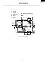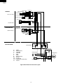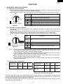
1
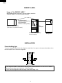
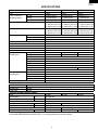
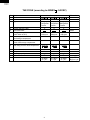
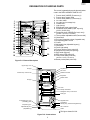
SJ-48H-S
SJ-51H-S
SJ-55H-S
SERVICE MANUAL
S0653SE55BPWI
REFRIGERATOR-FREEZER
MODELS
SJ-48H-S
SJ-51H-S
SJ-55H-S
In the interests of user-safety (Required by safety regulations in some
countries) the set should be restored to its original condition and only
parts identical to those specified should be used.
This equipment complies with
the requirements of Directives
89/336/EEC and 73/23/EEC as
amended by 93/68/EEC.
DESTINATION ......................... E, I
Refrigerant; HFC-134a
Refer to "HFC-134a COOLING UNIT" Service Manual for handling this refrigerant.
TABLE OF CONTENTS
page
ENERGY LABEL ....................................................................................................................................................2
INSTALLATION ......................................................................................................................................................2
SPECIFICATIONS .................................................................................................................................................3
THE FICHE ............................................................................................................................................................ 4
DESIGNATION OF VARIOUS PARTS .................................................................................................................. 5
LIST OF ELECTRICAL PARTS ............................................................................................................................. 6
WIRING DIAGRAM ................................................................................................................................................7
FUNCTIONS ..........................................................................................................................................................9
MODIFICATION PROCEDURE OF THE DOOR OPEN SIDE ............................................................................ 12
ASSEMBLING PROCEDURES OF MAIN PARTS AND CAUTIONS .................................................................. 14
COOLING UNIT ...................................................................................................................................................20
REPLACEMENT PARTS LIST ............................................................................................................................ 22
SHARP CORPORATION
1
SJ-48H-S
SJ-51H-S
SJ-55H-S
ENERGY LABEL
Usage of "the ENERGY LABEL"
When displaying this refrigerator in the shop-window, attach the
"ENERGY LABEL" to it in the following procedure.
E
Fix the data part of
"ENERGY LABEL (DATA)"
on the data part of
"ENERGY LABEL (BASE)"
A
B
C
D
E
F
G
"ENERGY LABEL (DATA)"
(This label is in Operation manual)
Data part
"ENERGY LABEL (BASE)"
of each language
Refrigerator
INSTALLATION
Free standing type
To ensure adequate ventilation for this refrigerator, install with 6 cm space at the rear and both sides, with a
minimum space of 9 cm above the refrigerator.
9cm
6cm
6cm
This refrigerator shall be used under the ordinary place condition between +5˚C and +43˚C of ambient
temperature, and also not be left under -10˚C for long days.
To be used this refrigerator within the range of the rated voltage ±10%.
2
SJ-48H-S
SJ-51H-S
SJ-55H-S
SPECIFICATIONS
Items
Type
Outer dimensions
(Including spacer)
Height
Width
Depth
Rated storage volume
Rated gross volume
Defrosting
Temperature control
No-frost freezer
Interior lamp
Caster
Evaporating pan
Refrigerator
Compartment
Freezer
Compartment
System
Start
Finish
Refrigerator shelf S
Refrigerator shelf L
Glass shelf
Fruit and Vegetable case
Egg pocket
Egg holder
Bottle pocket
Free pocket
Chilled case
Freezer shelf L
Freezer shelf S
Ice cube maker
Ice cube box
SJ-48H
SJ-51H
2-Door
2-Door
1620mm(63.8")
1700mm(66.9")
735mm(28.9")
735mm(28.9")
705mm(27.8")
705mm(27.8")
434 liter (15.3 cu.ft) 464 liter (16.4 cu.ft)
F: 139 liter (4.9 cu.ft) F: 139 liter (4.9 cu.ft)
R: 295 liter(10.4 cu.ft) R: 325 liter(11.5 cu.ft)
475 liter (16.8 cu.ft) 505 liter (17.8 cu.ft)
F: 163 liter (5.8 cu.ft) F: 163 liter (5.8 cu.ft)
R: 312 liter(11.0 cu.ft) R: 342 liter(12.0 cu.ft)
Heater system
Automatic
Automatic
Automatic (Adjustable)
Yes
1
4
1
—
1
1
1
1
1
1
2
2
1
1
1
1
Twin ice cube maker
1
No
Deodorizing system
COLOR
Items
SJ-48H-S, SJ-51H-S, SJ-55H-S
Outside color
White
Inside color
White
SOURCE, RATING AND NET WEIGHT
Items
SJ-48H
SJ-51H
Rated voltage
(V)
220/230/240
Rated frequency
(Hz)
50
Climate class
T
Rated input
(W)
172/178/184
182/186/190
Rated input of heating elements (W)
137/150/163
Refrigerant (Charging quantity)
HFC-134a(125g)
HFC-134a(130g)
Net Weight
(kg)
79
84
OPTIONAL ITEM
SJ-L815HD (REFRIGERATOR HINGE KITS). For changing the door to left side opening.
3
SJ-55H
2-Door
1820mm(71.7")
735mm(28.9")
705mm(27.8")
509 liter (18.0 cu.ft)
F: 139 liter (4.9 cu.ft)
R: 370 liter(13.1 cu.ft)
550 liter (19.4 cu.ft)
F: 163 liter (5.8 cu.ft)
R: 387 liter(13.6 cu.ft)
1
2
2
SJ-55H
88
SJ-48H-S
SJ-51H-S
SJ-55H-S
THE FICHE (according to ANNEX
NO.
1
2
3
Items
Trade mark
Model name
Type
: 94/2/EC)
Description
Remarks
SJ-48H
SJ-51H
SJ-55H
Category; 7 Category; 7 Category; 7
Refrigerator/ Refrigerator/ Refrigerator/
Freezer
Freezer
Freezer
E
E
E
864
kWh/year
864
kWh/year
934
kWh/year
Net storage volume of fresh
food storage compartment
304 L
334 L
382 L
8
Net storage volume of fresh
frozen food storage compartment
139 L
139 L
139 L
9
Star rating of frozen food compartment
4-STAR
4-STAR
4-STAR
No frost
7h
8 kg /24h
T
No frost
7h
8 kg /24h
T
No frost
7h
8 kg /24h
T
41 dB(A)
re 1 pw
41 dB(A)
re 1 pw
41 dB(A)
re 1 pw
4
5
6
Energy efficiency class
Eco-award mark
Energy consumption
(220V 50Hz at 25˚C)
7
10
11
12
13
14
No frost
Temperature rise time
Freezing capacity
Climate class
Noise
4
880/92
EN153
86/594/EEC
dB(A) re 1 pw
SJ-48H-S
SJ-51H-S
SJ-55H-S
DESIGNATION OF VARIOUS PARTS
The names in parenthesis are the denominations
used in the REPLACEMENT PARTS LIST.
1
2
3
4
19
5
20
17
18
6
21
22
7
8
9
10
11
12
13
14
23
24
15
20
16
1.
2.
3.
4.
5.
6.
7.
8.
9.
10.
11.
12.
13.
14.
15.
16.
17.
18.
19.
20.
21.
22.
23.
Freezer shelf (LARGE) (Freezer tray L)
Freezer temp. control knob
Freezer shelf (SMALL) (Freezer tray S)
Ice cube maker
Ice cube box (Ice storage box)
Chilled case
Light (Lamp)
Refrigerator temp. control knob
Reversible shelf (SMALL) (Ref. tray ass'y)
(SJ-51H, SJ-55H only)
Reversible shelf (LARGE) (Ref. tray L ass'y)
(SJ-48H 1, SJ-51H 1, SJ-55H 2)
Three position adjustable shelf (Free set shelf)
Glass shelf
Fruit and Vegetable crisper (Vegetable case)
Evaporating pan & Cover
Caster
Adjustable feet (Adjustable leg ass'y)
Fan switch
Fan & light switch
Freezer pocket (F door pocket HS)
Magnetic door seal (Door packing)
Egg holder (Egg tray)
Egg pocket (Egg pocket HS)
Free pocket (Utility pocket HS)
(SJ-48H 1, SJ-51H 1, SJ-55H 2)
24. Bottle pocket (Bottle pocket HS)
Figure D-1. External Description
Upper hinge cover
Mark: Cold air flow
Propeller fan
Hot pipe
Fan motor
Defrost thermostat
Freezer temp. control knob
Evaporator
Hot pipe
Freezer
compartment
Refrigerator
compartment
Defrost heater
Timer
Damper thermostat
Refrigerator temp. control knob
Drain pipe
Vegetable case
Evaporating pan cover
(Ventilating grille)
Compressor
Starting relay, Overload relay(Protector)
Evaporating pan
Sub condenser
Adjustable leg ass'y
(Adjustable leg)
Caster
This figure shows SJ-51H.
Figure D-2. Constructions
5
SJ-48H-S
SJ-51H-S
SJ-55H-S
LIST OF ELECTRICAL PARTS
ITEMS
F-Thermostat
Defrost thermo.
Thermo. fuse
Fan motor
Defrost heater
Door switch
Damper thermostat
Defrost timer
TYPE NAME
MM1-8025
US-602S
MGT4A50072
3R00044B
MM6-4015
MM1-7B01
MM1-6129
TMDF904FD2
RATING
250V 3A
250V 8A
250V 10A
220 - 240V 50Hz
at 230V 150W(220-240V)
250V 0.25A
—
220-240V
50Hz
Lamp socket
Lamp
SJ-51H, SJ-55H
Compressor
—
—
250V 1A
240V 10W
GL-99BH
220-240V/50Hz
Starting relay
PTH490D35AS
140N320-T
4TM308NFBYY
—
—
Cooling capacity : 210kcal/h(50Hz)
Main/Aux. coil : 8.5/15.0Ω(at 20˚C)
14Ω±20%
—
400VAC 6µF
Open/ Close : 120/61˚C
—
GL-90BH
220-240V/50Hz
PTH490D35AS
140N320-T
4TM276NFBYY
—
—
Cooling capacity : 192kcal/h(50Hz)
Main/Aux. coil : 8.8/17.7Ω(at 20˚C)
14Ω±20%
—
400VAC 6µF
Open/ Close : 120/61˚C
—
Protector
Running capacitor
SJ-48H
Compressor
Starting relay
Protector
Running capacitor
SPECIFICATIONS
(At normal notch)ON/OFF : -17/-22˚C
Open/Close : 10/1˚C
Working temp. : 72˚C
Working with ø100 fan
3 terminals push-button type
Open/Close : 0.5/-4˚C
Integration type
Cycle time : 10.8 hours(50Hz)
Delay time : 4.3 min.(50Hz)
E-12(Hard plastic body type)
E-12
COIL POSITION OF COMP.
Common
Aux. coil
6
Main coil
SJ-48H-S
SJ-51H-S
SJ-55H-S
WIRING DIAGRAM
Be sure to replace the electrical parts with specified ones for maintaining the safety and performance of the set.
G
Br
O
Y
R
P
B
Bk
S-B
G-Y
W
: GRAY
: BROWN (live)
: ORANGE
: YELLOW
: RED
: PINK
: BLUE (neutral)
: BLACK
: SKY-BLUE
: GREEN-YELLOW (earth)
: WHITE
CONNECTED IN TERMINAL BOX
CONNECTOR
TIMER
THERMOSTAT
(Br)
TM
(R)
(G)
INTERIOR
LIGHT
(Bk)
FAN
MOTOR FM
L
3PIN
PLUG/
CORD
(S-B)
THERMO.
FUSE
(O)
L
OVERLOAD
RELAY
DEFROST
HEATER
N
(G-Y)
(P)
(W)
DOOR SWITCH
(Bk)
STARTING
RELAY
DEFROST
THERMOSTAT
N
C
M
A
(B)
COMPRESSOR
RUNNING CAPACITOR
Figure W-1. Wiring Diagram
7
SJ-48H-S
SJ-51H-S
SJ-55H-S
Fan motor
Defrost thermo. FM
F-thermostat
FREEZER
(E.V cov. ass'y)
Thermo. fuse
Defrost heater
C1(LR-09-1V)
(O)
1
2
3
4
5
6
7
8
9
1
2
3
4
5
6
7
8
9
1
2
1 (W)
2
(G)
(P)
(B)
(Br)
(R)
(Bk)
(W)
(Y)
C2(ELR-02V)
Door switch
3(Push close)
1
4(Push open)
3
1
4
(C-part. ass'y)
REFRIGERATOR
C3(ELR-06V)
1 1 1 (O)
2 2 2
3 3 3 (S-B)
4 4
5 5
6 6
(B)
C4(LR-09-1V)
Defrost timer
(RC-box ass'y)
TM
Lamp
3
2
4
1
L
1
2
3
4
5
6
7
8
9
1
2
3
4
5
6
7
8
9
(R)
(Bk)
(G)
(Y)
(P)
(S-B)
(Br)
MACHINE ROOM
CE-2
CE-5
CE-2
(Br)
(B)
(G)
Terminal box
G
Br
O
Y
R
P
B
Bk
S-B
G-Y
W
Terminal cover
: GRAY
: BROWN (live)
: ORANGE
: YELLOW
: RED
: PINK
: BLUE (neutral)
: BLACK
: SKY-BLUE
: GREEN-YELLOW (earth)
: WHITE
Overload
relay
1
L
E
Source plug
N
Compressor
C
M
A
Running capacitor
Figure W-2. Electric Accessories Layout
8
(G-Y)
Starting relay
SJ-48H-S
SJ-51H-S
SJ-55H-S
FUNCTIONS
1. ADJUSTABLE TEMPERATURE CONTROL
(1) Temperature control of freezer
Thermostat (senses freezer temperature) operates on ON/OFF switchover to control the compressor and
allows the freezer temperature to keep at a suitable temperature.
However adjust the freezer temp. control knob as follows depending upon the storing condition of foods.
3
MED
4 5
2
7
MAX
Coldest
1
MIN
PURPOSE
KNOB
SETTING
6
MAX(Coldest)
For making ice rapidly or fast freezing.
When restocking with fresh food.
For normal freezing.
MED
For storing frozen food for a short period (up to one month).
FREEZER TEMP. CONTROL
When frozen food or ice cream is not stored.
MIN
Figure F-1.
(2) Temperature control of refrigerator
Damper-thermostat senses temperature of the refrigerator and changes the opening angle of the damper
automatically.
However, as the Damper-thermostat has no function to switch on or off the compressor and cool air circulating
fan, the freezer temperature control causes temperature in the refrigerator to vary to some extent.
However, adjust the refrigerator temp. control knob as follows depending upon the cooling condition.
MED
4
3
CHILLED
ZONE
(Coldest)
6
2
CHILLED
ZONE
MIN 1
For keeping freshness of food longer.
When the refrigerator does not provide sufficient cooling.
7 Coldest
For normal operation.
MED
REFRIGERATOR TEMP. CONTROL
When the refrigerator provides excessive cooling.
Figure F-2.
NOTE:
PURPOSE
KNOB
SETTING
5
MIN
The refrigerator temperature is affected also by the freezer temperature. If the freezer temp. control
knob is set at the position "MAX", the temperature tends to be lower than the following values, and if
set at near the position "MIN", temperature tends to be higher.
If the refrigerator is operated for a long time with the freezer temperature control sets the "MAX"
position, foods stored in the refrigerator compartment may also freeze.
When refrigerator temperature control sets to the "CHILLED ZONE", some foods stored may freeze.
In this case adjust control set back to the "MED" position.
When refrigerator temperature control sets to the "CHILLED ZONE", some foods stored in fresh cases
may also become frozen.
(3) Reference value of temperature
SETTING OF
FREEZER TEMP.
CONTROL KNOB
MAX
(Coldest)
MED
MIN
Freezer
temperature
Approx.
-21˚C
Approx.
-18˚C
Approx.
-15˚C
CHILLED
ZONE
(Coldest)
MED
MIN
Refrigerator
temperature
Approx.
0˚c
Approx.
3˚c
Approx.
6˚c
Chilled room
temperature
Approx.
-3˚c
Approx.
1˚c
Approx.
4˚c
SETTING OF
REFRIGERATOR TEMP.
CONTROL KNOB
The values shown above refer to the case where the
freezer temp. control knob is set at "MED".
The values shown above refer to the measurement carried out center area and 1/3 of overall height from the bottom at
each of the refrigerator and the freezer after machine has been operated at an ambient temperature of 30˚C with no food
stored and the door closed until the temperature is stabilized.
The values vary depending upon frequency of opening and closing the door, ambient temperature, amount of stored
foods and manner of storing foods.
9
SJ-48H-S
SJ-51H-S
SJ-55H-S
2. DEFROSTING
(1) No defrosting operation is necessary
No defrosting operation is necessary.
As this machine is so designed that a built-in
evaporator cools air and a fan circulates cooled air,
neither the freezer nor the refrigerator is frosted,
though the evaporator is frosted.
The frosted evaporator is defrosted automatically
due to the function of defrosting timer and heater,
requiring no defrosting operation.
(2) Where is melted ice brought
1. Melted ice is brought into the evaporating pan
at the bottom of the set and is evaporated here
by the heat of sub condenser.
2. Be sure to use the evaporating pan as inserted
so as to be level with the outer case.
(3) The following circuit diagrams in the table show automatic defrosting function of the refrigerator with
timer and defrost thermostat.
Operation
1. Cooling
(Normal)
Electric diagram
Defrost thermostat ON
Compressor running
Timer motor running
Thermo. fuse
Defrost heater
TM
Defrost
thermostat (ON)
COMP
Compressor
Timer contact
Timer motor
SOURCE
Thermostat
Description
The integration timer integrates running
time of the compressor. When it reaches
10 hours 50 min. at 50Hz, the timer
contact is changed to start defrosting.
Figure F-3.
Defrost thermostat ON
(Time 20 to 30 min.)
Thermo. fuse
Defrost heater
TM
Defrost
thermostat (ON)
COMP
Compressor
Timer motor stops
Timer contact
Thermostat
SOURCE
Compressor stops
Timer motor
2. Defrosting
The timer contact is changed to start
defrosting, the timer motor stops, and
power is supplied to the defrost heater.
It takes about 20 to 30 min. to defrost.
When little frosted, the defrosting takes
little time. When much frosted, the defrosting takes much time.
Figure F-4 .
Defrost thermostat OFF
Thermo. fuse
Defrost heater
TM
Defrost
thermostat (OFF)
COMP
Compressor
Thermostat
SOURCE
Compressor stops
Timer motor running
Timer contact
(Time approx. 5 min.)
Timer motor
3. Drain
When the defrost thermostat becomes
OFF, the timer motor starts running.
During the operation time(4 min. 20sec.
/50Hz) defrosted water is drained outside
the refrigerator.
Figure F-5.
Defrost thermostat OFF
Timer motor stops
Timer contact
Thermo. fuse
Defrost heater
TM
Defrost
thermostat (OFF)
Figure F-6.
10
COMP
Compressor
SOURCE
Thermostat
Compressor running
Timer motor
4. Restart
Timer contact is changed to cooling
operation and the compressor starts
running and the timer motor stops.
Defrost thermostat contact becomes ON
when it's cooled. And the timer motor
starts running. (Figure F-3.)
SJ-48H-S
SJ-51H-S
SJ-55H-S
(4) As a reference to determine the causes of trouble, malfunction and phenomena are described below.
Refer to the following when repairing.
1. Disconnection of defrost heater
As off-cycle defrosting is performed, the defrosting time is extremely prolonged. Each time defrosting is
started, the freezer temperature rises and a portion of ice and stored foods are melted.
2. Melted thermo. fuse or opened-circuit due to the defect of defrost thermostat.
When the above mentioned trouble occurs in cooling operation, the timer motor does not run, defrosting will
not take place, and consequently freezing is caused. In the above mentioned condition, when the timer shaft
is turned by hand to defrost, the timer motor runs during the operation time. However, the motor stops from the
time when the contact is changed, and freezing causes.
NOTE:
As the thermo. fuse assembly is intended to prevent dangers, do not use it under shorted condition even for
a short period.
3. DEW PREVENTION
The hot pipe, namely D.P.-condenser, is arranged around the flange part of
cabinet and the C-partition plate, preventing dew from being generated on the
cabinet.
NOTE:
D.P.-condenser pipe may be felt hot if touched by hand while the compressor
is in operation.
If you are asked about this, please explain that the hot pipe serve to
prevent the dew generation.
Hot pipe
Figure F-7.
4. INSPECTION OF INITIAL STARTING
(1) Inspection of cooling unit
1. Set the temperature control knob to "MAX" and check that the compressor starts to operate.
2. Depress the door switch to run the fan and check that cool air is blown out of the cold air outlet of the freezer
and the refrigerator.
3. When the compressor does not work, check that the timer is not set to "defrost" position.
4 It takes about an hour and a half or two hours to put food in the refrigerator after starting operation.
NOTE:
After return the temperature control knob to "MED" position.
When the refrigerator is operated initially after installed, the compressor may vibrate excessively for 1 to 2
min. However, vibration becomes normal if it is continuously operated.
(2) Inspection of defrost device
Operate the refrigerator for 20 to 30 min. and then check the defrost device in the following procedures :
Allow 5 min. to restart the compressor since immediate starting after stopping will cause unsmooth operation.
1. Turn the timer shaft clockwise with a screw driver.
At this time, make certains the timer clinks and the compressor stops.
2. After more than 5 min., turn the shaft further to operate.
Make certain cooling operation is started again.
NOTE:
It's not necessary to switch the timer by changing of source frequency (50Hz, 60Hz).
11
SJ-48H-S
SJ-51H-S
SJ-55H-S
MODIFICATION PROCEDURE OF THE DOOR OPEN SIDE
It is possible to change the door to left side opening.
To modify the door to left side opening, REFRIGERATOR HINGE KITS (for left side opening) SJ-L815HD (optional item )is necessary.
SJ-L815HD OPERATION MANUAL
REFRIGERATOR HINGE KITS (for left side opening)
Model
SJ-L815HD
These kits are used to change the refrigerator doors from right to left opening.
If you wish to change the door to left opening for some reason, such as restricted installation
space, ask your authorized service agent for this modification.
Parts list
A
Bottom hinge L
E
Nylon bearing (for lower door)
B
Stopper spring L (for upper door)
F
Bearing cap
G
C
Stopper spring L (for lower door)
Screw cover (2 pieces)
H
D
Screw cover
Nylon bearing (for upper door)
J
Silicon grease
Tools required
Cross head and flat blade screwdrivers
Socket wrench or spanner (8 mm) (The socket wrench or spanner is used to detach and attach hinges.)
Caution
Caution should be taken when handling the doors. These are heavy and could cause personal injury if mis-handled.
Always tighten screws securely.
Reattach the door paying careful attention to the door alignment.
Failure to fit the door correctly might cause cooling air to leak out and lower the refrigerating capability.
Fitting Instruction
Symbols used in the drawing have the following meanings.
1 - 18 : Modification procedure No.
: Detach/Attach
: Move
1.
2.
3.
4.
5.
6.
7.
8.
9.
10.
11.
12.
13.
14.
15.
16.
17.
18.
19.
Remove the evaporating pan cover, upper hinge cover, and 2 screw covers.
(Carefully remove the upper hinge cover using a screwdriver, making sure that the door cap is not damaged.)
Remove the upper hinge and detach the upper door. (To remove the door, lift it off the center hinge.)
Remove the center hinge and lift the lower door off the bottom hinge.
Remove the bottom hinge and spacer.
Remove the nylon bearing and bearing cap on the top of each door and attach the parts D, E, and F.
Remove the door stopper and stopper spring on the bottom of each door.
Remove the screw on the left of the door bottom and make a hole with a screwdriver for the insertion of the stopper spring.
Attach each door stopper and the parts B and C.
Apply silicon grease J to the shaded portion
of the part A and attach it to the left side together with the spacer.
Insert the lower door and fit the center hinge. If the washer is provided, install it ON top. Tighten the screws temporarily.
Fit the upper door and attach the upper hinge. Tighten the screws temporarily.
Adjust the alignment of the door. Ensure that the gap between the cabinet and door cap is 11.3 mm. Tighten the upper hinge screws.
Secure the upper door. Open the lower door and tighten the center hinge screws. (No drawing is provided.)
Check that the distance to activate the door switch is correct and that each door opens and closes smoothly.
To readjust the door position, loosen the center and bottom hinges.
Apply silicon grease J to the shaded portion
of the door packing.
Attach the parts G and H.
Fit the cap in the evaporating pan cover into the notch on the right.
Reattach the evaporating pan cover and upper hinge cover.
After the above steps have been completed, check that each door functions correctly and that the interior lamp lights up and goes off when
the door is opened and closed. (No drawing is provided.)
12
7
15
C
5
E
B
D
8
8
5
F
13
6
5
6
5
10
1
18
17
A
9
10
1
11
18
3
4
2
9
1
G
16
H
2.5±1.0mm
11.3mm
1.0±1.0mm
14
12
1
SJ-48H-S
SJ-51H-S
SJ-55H-S
SJ-48H-S
SJ-51H-S
SJ-55H-S
ASSEMBLING PROCEDURES OF MAIN PARTS AND CAUTIONS
CAUTION: DISCONNECT THE UNIT FROM THE POWER SUPPLY BEFORE ANY REPAIRING.
1. R-CONTROL COV. ASSEMBLY
A-sealer air guid. B
Defrost timer
D timer lead ass'y
A-sealer air guid. D
Lamp socket
R-air guider B
R-air guider A
A-sealer
RC-box
Damper
thermostat
A-sealer
RC-duct
RA-insulation
Lamp
C-box base
Thermo. cap sealer
Warning label
Dial sealer
A-sealer thermo. cap
A-sealer air guid. C
A-sealer air guid. D
R-temp. control knob
R-Cbox cover
(1) Sticking of sealer
R-air guider B
R-air guider A
A-sealer
air guid. D
R-air guider A
A-sealer
thermo. cap
R-air guider A
A-sealer
air guid. B
Dial
sealer
A
R-air guider B
A
Start
Finish
datum
(all round)
SEC. AA
A-sealer air guid. C
Insert RA-insulation
Start
R-air guider A
Overlap
RA-insulation
14
SJ-48H-S
SJ-51H-S
SJ-55H-S
C-box base
Start
A sealer air guid. C
Overlap
B
datum
A-sealer
RC-duct
A-sealer
RC-box
B
A-sealer RC-duct
A-sealer
RC-box
datum
Start
C-box
base
Overlap
(The back of C-box base)
SEC. BB
5±1 mm
3±1 mm
Damper
thermostat
Less than 130 mm
(2) Forming sensor of Damper thermostat
Stick thermo.
cap. sealer
25±2 mm
Less than 12 mm
NOTE
Minimum bending radius is R5.
There should be no gas leak by reforming of sensor tube.
(3) Setting of C-box base, Damper thermostat, R-air guider A and R-air guider B
R-air guider B
Damper thermostat
C-box base
Screw
Bend the senser
tube of Damper thermostat
Fix with claw
R-air guider A
A-sealer air guid. D
Paper tape(40 x 100 mm)
15
SJ-48H-S
SJ-51H-S
SJ-55H-S
(4) Fixing of Lamp socket, Defrost timer
SKY-BLUE
Insert Pin No.6
D timer
lead ass'y
Connect
Defrost timer
R-Cbox cover
6
7
BROWN
Insert Pin No.7
Lamp
socket
Screw
Lamp
(5) Fixing of R-Cbox cover
Claws(2 places)
Set R-temp. control knob
R-Cboxcover
Claws(2 places)
2±1 mm
Stick Lamp label
LAMP RATING
240V. 10W
4±1 mm
16
SJ-48H-S
SJ-51H-S
SJ-55H-S
2. E.V COVER ASSEMBLY
F-thermostat
Lead E.V cover ass'y.
E.V cover sealer E
L-band C
E.V cover sealer B
E.V cover
E.V cover sealer C
Fan clamp
Propeller fan
L-band C
Fan motor cushion A
Defrost thermo. ass'y
Fuse ass'y
Motor cushion
Alminum tape
Fan motor
Fan motor cushion B
E.V cover sealer A
(1) Sticking of sealer to E.V cover
E.V cover sealer A
Overlap
10mm(min.)
E.V cover sealer B
E.V cover
[View from A direction]
[Front View]
E.V cover sealer E
E.V cover
E.V cover
Along this edge
Fix E.V cover sealer E along the edge of E.V cover.
A
17
SJ-48H-S
SJ-51H-S
SJ-55H-S
(2) Fixing of Fan motor and Fan
Motor cushion
Motor cushion
Fan motor cushion B
Fan motor cushion A
Fan motor
cushion B
Fan motor
cushion A
D
C
2 mm
C
D
Motor
cushion
-2
Motor
cushion
Sec CC
See DD
Motor cushion
Motor cushion
Fan motor cushion B
Fan motor cushion A
Fan motor
Check claw is surely fixed
to the hole of Fan motor cushion.
Set Fan clamp to Propeller fan and insert it to the shaft of Fan motor.
Propeller fan
E .V cover
-1~1mm
Fan clamp
Slit
Shaft
More than 3mm
Slit of each Fan clamp and Propeller fan should not be at same position.
18
SJ-48H-S
SJ-51H-S
SJ-55H-S
(3) Wiring of Lead Wire
B
B
L-band C
Defrost
thermo. ass'y
C
Alminum tape
L-band C
Fuse ass'y
A
B Detail
A Detail
C Detail
Bend this pin
Fasten Defrost thermo. ass'y's
wires as bellow.
And set it inside of the four pins.
7mm
Lead wire “WHITE”
Cut off to
7mm or shorter
Fuse ass'y
Alminum tape
Horizontally
Thermo. sensing element side
(Silver metal)
(4) Setting of Lead E.V cover ass'y and F-thermostat
E.V cover
Lead E.V cover
ass'y
Standard line
Set surely edges of these two ribs.
Through between ribs
10mm over
Inside of ribs
Under 5mm
F-thermostat
Color: RED
(5) Wiring of Connector
A
3 2 1
6 5 4
9 8 7
View from A
Color: BROWN
(6) Fixing of E.V cover sealer C
1. Lead E.V cover ass'y
2. Lead E.V cover ass'y
3. Pink lead of Defrost thermo. ass'y
4. Blue lead of Defrost thermo. ass'y
5. Lead E.V cover ass'y
6. Lead E.V cover ass'y
7. Black lead of Fuse ass'y
8. White lead of Fuse ass'y
9. No connect
19
130 mm
E.V cover
E.V cover sealer C
SJ-48H-S
SJ-51H-S
SJ-55H-S
COOLING UNIT
SJ-48H
Mark: Refrigerant flow
Mark: Brazing portion
Hot pipe L
(Side condenser)
Hot pipe
(DP-condenser)
Hot pipe R
(Side condenser)
Evaporator
Suction pipe
Sub. condenser
Compressor
Capillary tube
Dryer
Figure C-1. Cooling unit
Dryer
Capillary tube
Charge pipe L
Hot pipe
Sub. condenser
Evaporator
Charge pipe L
Compressor
Suction pipe
S.P. connector
Sub. condenser
Figure C-2. Location
20
SJ-48H-S
SJ-51H-S
SJ-55H-S
SJ-51H, SJ-55H
Mark: Refrigerant flow
Mark: Brazing portion
Hot pipe L
(Side condenser)
Hot pipe
(DP-condenser)
Hot pipe R
(Side condenser)
Back condenser
Evaporator
Suction pipe
Sub. condenser
Compressor
Connector pipe
Capillary tube
Dryer
Figure C-3. Cooling unit
Dryer
Capillary tube
Charge pipe L
Hot pipe
Sub. condenser
Evaporator
Charge pipe L
Connector pipe
Compressor
Suction pipe
S.P. connector
Sub. condenser
Figure C-4. Location
21
Back condenser
SJ-48H-S
SJ-51H-S
SJ-55H-S
REPLACEMENT PARTS LIST
REF. NO.
PART NO.
DESCRIPTION
Q'TY
CODE
SJ-48H
-S
SJ-51H
-S
SJ-55H
-S
1
1
1
1
1
1
1
1
1
1
1
1
1
1
1
1
1
1
1
1
1
1
1
1
1
1
1
1
1
1
1
1
1
1
1
1
1
1
1
1
1
1
1
1
1
1
1
1
1
1
1
1
1
1
1
1
1
BA
AQ
BB
AZ
AQ
AZ
AN
AH
AV
AZ
AP
AN
AN
AX
AN
AN
AP
AR
AM
AE
1
1
1
2
1
1
1
1
1
1
1
1
1
2
1
1
1
1
1
1
1
1
1
1
1
1
1
2
1
1
1
2
1
2
1
1
2
1
1
1
1
1
2
1
1
1
1
2
1
1
1
1
1
1
1
1
1
2
1
1
1
1
1
1
1
1
1
1
1
1
1
2
1
1
1
2
1
2
1
1
2
1
1
1
1
1
2
1
1
1
1
2
1
1
1
1
1
1
1
1
1
2
1
1
1
1
1
1
1
1
1
1
1
1
1
2
1
1
1
2
1
2
1
1
2
1
1
1
1
1
2
1
AL
AD
AQ
AD
AE
AQ
AE
AD
AH
AG
AH
AV
AD
AF
AD
AD
AD
AC
AE
AF
AT
AW
AD
AD
AE
AE
AD
AC
AH
AK
AD
AB
AG
AD
AL
AL
AE
AE
AE
AB
AC
AD
AD
AK
AF
AE
AB
AD
ELECTRIC PARTS
1- 1
1- 2
1- 3
1- 4
1- 5
1- 6
1- 7
1- 8
1- 9
1- 9
1-10
1-11
1-11
1-15
1-17
1-19
1-20
1-21
1-22
1-25
RTHM-A057CBE0
RSTT-A126CBE0
QSWTDA035CBE0
PDMP-A025CBE0
FTHM-A012CBK0
RMOTRA040CBE0
QSOCAA047CBE0
RLMP-A012CBE0
QACC-A097CBE0
QACC-A104CBE0
QSW-PA056CBEA
RHOG-A084CBE0
RHOG-A091CBE0
RC-EZA124CBE0
FFS-TA036CBK0
FW-VZA109CBE0
FW-VZA110CBE0
FHETBA112CBE0
FCNW-A517CBK0
QTAN-A032CBE0
F-Thermostat
Starting Relay
Defrost Timer
Damper Thermostat
Defrost Thermo.Ass’y
Fan Motor
Lamp Socket
Lamp
Source Cord(Plug type CS)
Source Cord(Plug type BF)
Door Switch
Protector
Protector
Running Capacitor
Fuse Ass’y
D Timer Lead Ass’y
Lead EV-Cover Ass’y
Def.Heater Ass’y
Relay Cord S Ass’y
Terminal Block
2- 2
2- 4
2- 7
2- 7-1
2- 7-2
2- 8
2- 8-2
2-11
2-13
2-14
2-15
2-16
2-17
2-19
2-20
2-21
2-22
2-23
2-24
2-26
2-27
2-28
2-29
2-31
2-33
2-34
2-36
2-37
2-38
2-39
2-40
2-41
2-42
2-49
2-55
2-55
2-56
2-56
2-56
2-57
2-57
2-60
2-61
2-62
2-63
2-64
2-65
2-66
JKNB-A036CBFA
LPLTMA404CBE0
FLEGPA045CBK0
FAJS-A009CBK0
LHLD-A354CBM0
FLEGPA046CBK0
LHLD-A355CBM0
PSPAVA078CBEA
DHNG-A281CBM0
DHNG-A283CBM0
DHNG-A282CBM0
GCOV-A141CBFA
LCRA-A010CBE0
LHLD-A389CBF0
NFANPA011CBF0
PSEL-B128CBE0
PSEL-B129CBE0
PSEL-A415CBE0
PCOVPA164CBFA
PCOV-A151CBFA
GCOVPA087CBRA
HGRL-A149CBRA
GCOV-A162CBFE
JKNB-A033CBFA
LRALPA114CBFA
LRALPA115CBFA
PCAP-A006CBFJ
PCAP-A056CBFA
PGID-A119CBF0
LFRM-A202CBFA
PFPFPA809CBF0
PSEL-B244CBE0
PGID-A118CBF0
LSTPPA074CBFA
HGRL-A134CBFA
HGRL-A135CBFA
PFPFPA814CBF0
PFPFPA824CBF0
PFPFPA954CBF0
PSEL-B130CBE0
PSEL-B143CBE0
LHLD-A391CBE0
LHLD-A391CBE0
DCOV-A061CBK0
LHLD-A388CBF0
LHLD-A392CBF0
PSEL-B259CBE0
PSHEMA132CBP0
F-Temp. Control Knob
FL Plate AL.
Leg Holder L Ass’y
Adjustable Leg Ass’y
Leg Holder L
Leg Holder R Ass’y
Leg Holder R
Bottom Hinge Spacer
Upper Hinge Ass’y
Bottom Hinge R Ass’y
Center Hinge R Ass’y
E.V Cover
Fan Clamp
Motor Cushion
Propeller Fan 100
E.V Cover Sealer A
E.V Cover Sealer B
E.V Cover Sealer C
Terminal Cover
Lamp Cover
R-Cbox Cover
Fan Louver
Upper Hinge Cover
R-Temp.Control Knob
C-Case Rail L
C-Case Rail R
Screw Cover
Screw Cover B
R-Air Guider A
C-Box Base
RA-Insulation
Thermo. Cap. Sealer
R-Air Guider B
C-Stopper
Multi Louver
Multi Louver
R-Louver Insu.
R-Louver Insu.
R-Louver Insu.
A-Sealer R-Louver
A-Sealer R-Louver
SL-5N Clip
SL-5N Clip
Harness Cover Ass’Y
Fan Motor Cushion B
Fan Motor Cushion A
Motor Cushion
Heater Cover AL
MECHANICAL PARTS
22
SJ-48H-S
SJ-51H-S
SJ-55H-S
REF. NO.
PART NO.
DESCRIPTION
2-67
2-70
2-71
2-72
2-73
2-74
2-75
2-76
2-78
2-79
2-80
2-81
2-82
2-83
2-84
2-86
LPLTMA403CBP0
PSEL-B167CBE0
PSEL-A552CBE0
PSEL-B120CBE0
PSEL-B121CBE0
PSEL-B122CBE0
PSEL-B124CBE0
LHLD-A124CBFB
LPLTMA399CBP0
LBND-A019CBE0
PBOX-A071CBFA
PPIPPA069CBE0
PTUBBA058CBE0
PSEL-B242CBE0
PSEL-B243CBE0
LBND-A026CBE0
Drain Support AL
E.V Cover Sealer E
Dial Sealer
A-Sealer RC-Box
A-Sealer RC-Duct
A-Sealer Thermo.Cap.
A-Sealer Air Guid.B
K-Frame Holder
Dryer Support
Nylon Band
Terminal Box
Drain Pipe S
Insulating tube
A-Sealer Air Guid.C
A-Sealer Air Guid.D
Nylon Band
3- 5
3- 5-1
3- 5-2
3- 5-3
3- 6
3- 9
3-10
3-12
3-14
3-15
3-15
3-15
3-15-1
3-15-2
3-15-3
3-15-4
3-16
3-16
3-16
3-17
3-17
3-17
3-20
3-20
3-20
3-25
FDORFA864CBK0
LSTPMA008CBM0
NBRGPA013CBFB
LSTPPA082CBFA
FPACGA204CBK0
GLIN-A145CBFA
PFPFPA810CBE0
PFPFPA852CBE0
PSEL-B126CBE0
FDORRA740CBK0
FDORRA743CBK0
FDORRA744CBK0
LSTP-A058CBM0
NBRGPA022CBFA
LSTPPA084CBFA
PCAP-A055CBFA
GLIN-A146CBFA
GLIN-A147CBEA
GLIN-A148CBEA
FPACGA205CBK0
FPACGA206CBK0
FPACGA207CBK0
PFPFPA811CBE0
PFPFPA819CBE0
PFPFPA822CBE0
HBDGDA759CBEC
F-Door Ass’Y
F-Door Stopper R
Nylon Bearing 2
FD-Stopper Spring R
F-Door Packing
F-Door Liner
F-Liner Plate
F-Liner Plate Bottom
F-Door Sealer
R-Door Ass’Y
R-Door Ass’Y
R-Door Ass’Y
R-Door Stopper R
Nylon Bearing 3S
RD-Stopper Spring R
Bearing Cap
R-Door Liner
R-Door Liner
R-Door Liner
R-Door Packing
R-Door Packing
R-Door Packing
R-Liner Plate
R-Liner Plate
R-Liner Plate
Badge
4- 1
4- 3
4- 9
4-14
4-15
4-17
LBND-A023CBE0
LX-VZA003CBE0
QTAN-A012CBE0
LX-WZA013CBE0
LX-BZA018CBE0
LX-WZA003CBE0
L-Band C
Special Screw
Solderless Term. B
Hinge Washer
Special Screw
Washer
5- 1
5- 2
5- 3
5- 4
5- 5
5- 6
5- 7
5- 9
5-11
5-12
5-13
5-14
5-15
5-16
5-17
5-18
5-19
UPOK-A120CBRA
UPOK-A117CBRA
UPOK-A119CBRA
UPOK-A118CBRA
UTNA-A167CBFC
FSRA-A149CBY0
LFRM-A200CBFA
USRA-A180CBFA
USRA-A179CBFA
HDECQA360CBEA
HGRL-A151CBFE
USRA-A177CBFA
UTNA-A227CBE0
UYOK-A180CBFA
UYOK-A087CBFF
UYOK-A179CBFA
GDORPA042CBRA
Bottle Pocket HS
Egg Pocket HS
F Door Pocket HS
Utility Pocket HS
Egg Tray
Ice Cube Maker
Ice Maker
Freezer Tray L
Freezer Tray S
Glass Shelf Trim
Ventilating Grille
Evaporating Pan
Glass Shelf
Vegetable Case
Ice Storage Box
Chilled Case
Chilled Door HS
Q'TY
CODE
SJ-48H
-S
SJ-51H
-S
SJ-55H
-S
1
1
1
1
1
1
1
1
1
3
1
1
1
2
2
1
1
1
1
1
1
1
1
1
1
3
1
1
1
2
2
1
1
1
1
1
1
1
1
1
1
3
1
1
1
2
2
1
AL
AB
AC
AB
AD
AB
AB
AH
AD
AB
AE
AH
AE
AC
AD
AD
1
1
1
1
1
1
2
1
3
1
1
1
1
1
1
1
2
1
1
1
1
1
1
1
2
1
3
1
1
1
1
1
1
1
2
1
1
1
1
1
1
1
2
1
3
1
1
1
1
1
1
1
2
1
BP
AD
AH
AD
AZ
AX
AD
AD
AG
BS
BS
BQ
AF
AC
AD
AB
BE
BA
AX
BB
BA
AZ
AF
AG
AF
AM
7
2
3
1
1
4
7
2
3
1
1
4
7
2
3
1
1
4
AC
AB
AH
AB
AA
AA
2
1
2
1
2
1
1
1
1
1
1
1
1
1
1
1
1
2
1
2
1
2
1
1
1
1
1
1
1
1
1
1
1
1
2
1
2
2
2
1
1
1
1
1
1
1
1
1
1
1
1
AQ
AM
AT
AM
AG
AU
AW
AX
AX
AK
AR
AS
BB
AZ
AM
AS
AP
DOOR PARTS
OTHER PARTS
ATTACHMENT PARTS
23
SJ-48H-S
SJ-51H-S
SJ-55H-S
REF. NO.
5-20
5-21
5-24
5-25
5-26
PART NO.
DESCRIPTION
UTNA-A230CBFA
UTNA-A229CBFA
FSRA-A160CBK0
FSRA-A161CBK0
PCAP-A053CBEE
Free Set Shelf F
Free Set Shelf B
Ref.Tray L Ass’y
Ref.Tray Ass’y
Venti.Grille Cap
Q'TY
CODE
SJ-48H
-S
SJ-51H
-S
SJ-55H
-S
1
1
1
1
1
1
1
1
1
1
1
2
1
1
AV
AS
BB
BA
AE
1
4
1
1
1
1
4
1
1
2
1
1
1
2
1
-
1
4
1
1
1
1
4
1
1
2
1
1
1
2
1
1
1
4
1
1
1
1
4
1
1
2
1
1
1
2
1
1
CA
BY
AD
AR
AP
AG
AX
AC
AB
AH
AC
AD
AH
AH
AH
BC
AF
AG
1
1
1
4
1
1
2
1
1
1
1
1
1
1
1
1
1
1
1
1
4
1
1
2
1
1
1
1
1
1
1
1
1
1
1
1
1
4
1
1
2
1
1
1
1
1
1
1
1
1
1
AG
AD
BF
BH
BF
AD
AY
AS
AD
AE
AH
AH
AG
AG
AG
AG
AG
AG
AG
AG
AG
CYCLE PARTS
6- 1
6- 1
6- 2
6- 3
6- 3
6- 4
6- 5
6- 6
6- 9
6-11
6-12
6-13
6-14
6-15
6-16
6-18
6-21
6-25
PCMPLA130CBE0
PCMPLA134CBE0
PSPAGA028CBE0
FCONSA051CBK0
FCONSA052CBK0
FFRM-A085CBK0
FDRY-A006CBK0
PCLI-A035CBE0
PSPAFA020CBE0
PPIPCA220CBE0
LANG-A024CBP0
LHLD-A061CBF0
PGUM-A002CBF0
PGUM-A003CBF0
PGUM-A004CBF0
PPIPCA222CBE0
PCOVPA165CBE0
PPIP-A066CBE0
Compressor
Compressor
Rubber Grommet
Sub. Condenser Ass’y
Sub. Condenser Ass’y
Base Frame Ass’y
Dryer Ass’y
Clip
Sleeve
S.P Connector
Absorbent Rubber CLM
Evaporating Pan Holder
Absorbent Rubber B
Absorbent Rubber B
Absorbent Rubber A
Charge Pipe L
Terminal Cover
Connector Pipe
MISCELLANEOUS
90-1
90-2
90-3
90-3
90-3
90-5
90-6
90-7
90-8
90-9
90-9
90-9
90-10
90-10
90-10
90-10
90-10
90-10
90-10
90-10
90-11
TINS-A333CBR0
TLAB-A092CBR0
SPAKCH396YDE0
SPAKCH399YDE0
SPAKCH401YDE0
TLAB-A635CBE0
CPADBA501YDK0
CPADBA495YDK0
TLAB-A636CBE0
TLAB-A656CBR0
TLAB-A663CBR0
TLAB-A664CBR0
TLAB-A637CBR0
TLAB-A638CBR0
TLAB-A639CBR0
TLAB-A640CBR0
TLAB-A641CBR0
TLAB-A642CBR0
TLAB-A643CBR0
TLAB-A644CBR0
TINS-A343CBR0
Operation Manual R
Lamp Label
Packing Case 51H
Packing Case 55H
Packing Case 48H
Case Label S
Bottom Pad Ass’y
Top Pad Ass’y
CE Label
Energy Label(Data)
Energy Label(Data)
Energy Label(Data)
Energy Label(GB)
Energy Label(D)
Energy Label(F)
Energy Label(E)
Energy Label(I)
Energy Label(GR)
Energy Label(P)
Energy Label(NL)
Operation Manual(only for U.K.)
HOW TO ORDER REPLACEMENT PARTS
To have your order filled prompty and correctly, please furnish the following information.
1. MODEL NUMBER
3. PART NO.
2. REF. NO.
4. DESCRIPTION
24
SJ-48H-S
SJ-51H-S
SJ-55H-S
2
1
4
3
6
5
DOOR PARTS
3-9
A
A
3-6
3-10
3-5-2
3-5
3-14
B
B
3-10
3-25
C
C
5-3
3-15-4
3-12
3-20
5-5
3-5-3 3-5-1
3-15-3
D
D
5-2
3-15
3-16
E
E
5-4
F
F
5-1
G
G
3-17
3-20
3-15-2
H
SJ-48H-S
SJ-51H-S
SJ-55H-S
3-15-1
1
2
4
3
25
5
6
H
SJ-48H-S
SJ-51H-S
SJ-55H-S
2
1
4
3
6
5
CABINET PARTS
2-65
A
2-16
2-28
2-21
A
2-64
1-6
2-20
2-17
2-70
4-1
1-5
2-4
2-60
2-63
1-20 2-19
1-17
2-2
2-29
4-1
B
B
2-13
2-22
2-62
1-1
2-23
2-81
5-7
5-6
2-66
C
2-36
C
1-21
5-17
2-76
5-11
2-33
2-79
2-37
5-18
4-9
2-67
5-9
1-10
4-14
2-24
2-78
6-18
4-3
6-5
D
D
2-15
5-26
2-82
2-49
2-34
2-80
5-13
2-75
2-79
1-9
2-11
5-19
1-22
2-72
E
2-40
1-7
1-3
2-8
2-84
E
1-19
2-14
2-8-2
2-73
2-38
1-8
2-61
2-7-1
2-39
2-7
2-7-2
2-7-1
2-71
6-14
2-42
6-11
2-41
2-84
F
4-17
6-1
6-18
2-26
2-27
F
1-11 6-6
6-25
2-31
2-86
6-15
1-4
90-2
6-16
6-12
6-9
6-2
2-57
2-83
4-15
6-21
2-74
2-56
2-55
G
G
1-2
5-12
5-25
1-25
1-15
5-24
6-4
5-15
5-16
6-3
6-13
5-21
H
5-14
5-20
1
2
4
3
26
5
SJ-48H-S
SJ-51H-S
SJ-55H-S
6
H
SJ-48H-S
SJ-51H-S
SJ-55H-S
PLUG TYPE
Type
Section of Power
Supply Cord
Plug
BF
Destination
I
(Only for U.K.)
with FUSED
CS
E
27
SJ-48H-S
SJ-51H-S
SJ-55H-S
28
'96 SHARP CORP. (0U0.25E) Printed in Japan