1
MITSUBISHI ELECTRIC
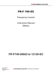
FR-F700
Inverter
Instruction Manual
FR-F740 EC
FR-F746 EC
Art. No: 166461
11 10 2010
Version E
MITSUBISHI ELECTRIC
INDUSTRIAL AUTOMATION
Instruction Manual
Inverter FR-F700 EC
Art. no.: 166461
A
B
Version
04/2005
07/2005
pdp
pdp
First Edition
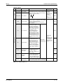
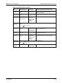
Section 3.8.1
Changes / Additions / Corrections
C
03/2006
pdp
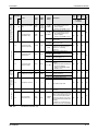
General
D
E
08/2010
10/2010
akl
akl
Section 2.4.3
General
General
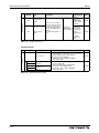
Section 7.2
General
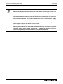
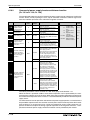
Revision of the section "Note on selecting a suitable power
supply ELCB"
Extension of the capacity classes by the inverters
FR-F740-02600 to 12120
Addition of the inverters FR-F746-00023 to 01160 with
IP54 protection rating
New parameter 299
Addition of a heatsink protrusion attachment
Adaption of document version numbers (english, german)
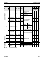
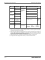
Additions:
• Voltage/current input switch
• Additional explanation to "Causes and corrective actions"
• DC feeding operation permission signal (X70), DC feeding
cancel signal (X71), PID integral value reset signal (X72)
• PID deviation limit signal (Y48), Pulse output of output power
signal (Y79), DC feeding signal (Y85)
New setting values:
• Pr. 29 Acceleration/deceleration pattern selection setting value
"6"
• Pr. 30 Regenerative function selection setting values "10", "11",
"20", "21"
• Pr. 59 Remote function selection setting values "11", "12", "13"
• Pr. 128 PID action selection setting values "110", "111", "120",
"121"
• Pr. 167 Output current detection operation selection setting
values "10", "11"
• Pr. 261 Power failure stop selection setting values "21", "22"
• Pr. 495 Remote output selection setting values "10", "11"
New parameters:
• Pr. 522 Output stop frequency
• Pr. 539 Modbus-RTU communication check time interval
• Pr. 653 Speed smoothing control
• Pr. 654 Speed smoothing cutoff frequency
• Pr. 553 PID deviation limit, Pr. 554 PID signal operation
selection, C42 (Pr. 934) PID display bias coefficient,
C43 (Pr. 934) PID display bias analog value, C44 (Pr. 935) PID
display gain coefficient, C45 (Pr. 935) PID display gain analog
value
• Pr. 799 Pulse increment setting for output power
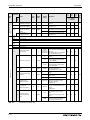
Section 7.6
Partial changes
• Pr. 153 Zero current detection time setting range "0 to 10s"
• Check first when you have a trouble
Thank you for choosing this Mitsubishi inverter.
This instruction manual provides instructions for advanced use of the FR-F700 series inverters.
Incorrect handling might cause an unexpected fault. Before using the inverter, always read this
instruction manual to use the equipment to its optimum.
Safety instructions
Do not attempt to install, operate, maintain or inspect the inverter until you have read through
this instruction manual carefully and can use the equipment correctly. Do not use the inverter until you have a full knowledge of the equipment, safety information and instructions. In this instruction manual, the safety instruction levels are classified into "WARNING" and "CAUTION".
P
WARNING:
E
CAUTION:
Assumes that incorrect handling may cause hazardous conditions, resulting in death
or severe injury.
Assumes that incorrect handling may cause hazardous conditions, resulting in medium or slight injury, or may cause physical damage only.
Note that even the CAUTION level may lead to a serious consequence according to conditions.
Please follow strictly the instructions of both levels because they are important to personnel
safety.
FR-F700 EC
I
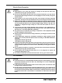
Electric Shock Prevention
P
WARNING:
● While power is on or when the inverter is running, do not open the front cover.
Otherwise you may get an electric shock.
● Do not run the inverter with the front cover removed. Otherwise, you may access
the exposed high-voltage terminals or the charging part of the circuitry and get an
electric shock.
● Even if power is off, do not remove the front cover except for wiring or periodic
inspection. You may access the charged inverter circuits and get an electric shock.
● Before starting wiring or inspection, check to make sure that the operation panel
indicator is off, wait for at least 10 minutes after the power supply has been switched
off, and check that there are no residual voltage using a tester or the like. The
capacitor is charged with high voltage for some time after power off and it is
dangerous.
● This inverter must be earthed. Earthing must conform to the requirements of
national and local safety regulations and electrical codes. (JIS, NEC section 250,
IEC 536 class 1 and other applicable standards)
● Any person who is involved in the wiring or inspection of this equipment should
be fully competent to do the work.
● Always install the inverter before wiring. Otherwise, you may get an electric shock
or be injured.
● If your application requires by installation standards an RCD (residual current
device) as up stream protection please select according to DIN VDE 0100-530 as
following:
Single phase inverter type A or B
Three phase inverter only type B.
● Perform setting dial and key operations with dry hands to prevent an electric shock.
Otherwise you may get an electric shock. Perform setting dial and key operations
with dry hands to prevent an electric shock. Otherwise you may get an electric
shock.
● Do not subject the cables to scratches, excessive stress, heavy loads or pinching.
Otherwise you may get an electric shock.
● Do not replace the cooling fan while power is on. It is dangerous to replace the
cooling fan while power is on.
● Do not touch the printed circuit board with wet hands. You may get an electric shock.
Fire Prevention
E
CAUTION:
● Install the inverter on a nonflammable wall without holes (so that nobody can touch
the inverter heatsink on the rear side, etc.). Mounting it to or near combustible
material can cause a fire.
● If the inverter has become faulty, switch off the inverter power. A continuous flow
of large current could cause a fire.
● Do not connect a resistor directly to the DC terminals P/+, N/–. This could cause a
fire and destroy the inverter. The surface temperature of braking resistors can far
exceed 100°C for brief periods. Make sure that there is adequate protection against
accidental contact and a safe distance is maintained to other units and system
parts.
II
Injury Prevention
E
CAUTION:
● Apply only the voltage specified in the instruction manual to each terminal. Otherwise, burst, damage, etc. may occur.
● Ensure that the cables are connected to the correct terminals. Otherwise, burst,
damage, etc. may occur.
● Always make sure that polarity is correct to prevent damage, etc. Otherwise, burst,
damage, etc. may occur.
● While power is on or for some time after power-off, do not touch the inverter as it
is hot and you may get burnt.
Additional Instructions
Also note the following points to prevent an accidental failure, injury, electric shock, etc.
Transportation and installation
E
CAUTION:
● When carrying products, use correct lifting gear to prevent injury.
● Do not stack the inverter boxes higher than the number recommended.
● Ensure that installation position and material can withstand the weight of the
inverter. Install according to the information in the instruction manual.
● Do not install or operate the inverter if it is damaged or has parts missing. This can
result in breakdowns.
● When carrying the inverter, do not hold it by the front cover or setting dial; it may
fall off or fail.
● Do not stand or rest heavy objects on the product.
● Check the inverter mounting orientation is correct.
● Prevent other conductive bodies such as screws and metal fragments or other
flammable substance such as oil from entering the inverter.
● As the inverter is a precision instrument, do not drop or subject it to impact.
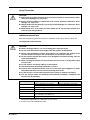
● Use the inverter under the following environmental conditions. Otherwise, the
inverter may be damaged
Operating Condition
Ambient temperature
FR-F700 EC
FR-F740
FR-F746
−10°C to +40/+50°C (non-freezing)
−10°C to +30/+40°C (non-freezing)
The maximum temperature depends on the setting of Pr. 570.
Ambient humidity
90% RH or less (non-condensing)
Storage temperature
−20°C to +65°C Atmosphere
Indoors (free from corrosive gas, flammable gas, oil mist, dust and dirt)
Altitude
Maximum 1000m above sea level for standard operation. After that derate by 3% for
every extra 500m up to 2500m (91%)
Vibration
5.9m² or less at 10 to 55Hz (directions of X, Y, Z axes)
Temperature applicable for a short time, e.g. in transit.
2.9m/s² or less for the 04320 or more.
III
Wiring
E
CAUTION:
● Do not install assemblies or components (e. g. power factor correction capacitors)
on the inverter output side, which are not approved from Mitsubishi.
● The direction of rotation of the motor corresponds to the direction of rotation
commands (STF/STR) only if the phase sequence (U, V, W) is maintained.
Operation
P
WARNING:
● When you have chosen the retry function, stay away from the equipment as it will
restart suddenly after an alarm stop.
● Since pressing STOP/RESET key may not stop output depending on the function
setting status, provide a circuit and switch separately to make an emergency stop
(power off, mechanical brake operation for emergency stop, etc.).
● Make sure that the start signal is off before resetting the inverter alarm. A failure
to do so may restart the motor suddenly.
● The inverter can be started and stopped via the serial port communications link or
the field bus. However, please note that depending on the settings of the
communications parameters it may not be possible to stop the system via these
connections if there is an error in the communications system or the data line. In
configurations like this it is thus essential to install additional safety hardware that
makes it possible to stop the system in an emergency (e.g. controller inhibit via
control signal, external motor contactor etc). Clear and unambiguous warnings
about this must be posted on site for the operating and service staff.
● The load used should be a three-phase induction motor only. Connection of any
other electrical equipment to the inverter output may damage the inverter as well
as the equipment.
● Do not modify the equipment.
● Do not perform parts removal which is not instructed in this manual. Doing so may
lead to fault or damage of the inverter.
IV
E
CAUTION:
● The electronic thermal relay function does not guarantee protection of the motor
from overheating. It is recommended to install both an external thermal and PTC
thermistor for overheat protection.
● Do not use a magnetic contactor on the inverter input for frequent starting/stopping
of the inverter. Otherwise, the life of the inverter decreases.
● Use a noise filter to reduce the effect of electromagnetic interference and follow
the accepted EMC procedures for proper installation of frequency inverters. Otherwise nearby electronic equipment may be affected.
● Take appropriate measures regarding harmonics. Otherwise this can endanger
compensation systems or overload generators.
● Use a motor designed for inverter operation. (The stress for motor windings is
bigger than in line power supply).
● When parameter clear or all clear is performed, set again the required parameters
before starting operations. Each parameter returns to the initial value.
● The inverter can be easily set for high-speed operation. Before changing its setting,
fully examine the performances of the motor and machine.
● The DC braking function of the frequency inverter is not designed to continuously
hold a load. Use an electro-mechanical holding brake on the motor for this purpose.
● Before running an inverter which had been stored for a long period, always perform
inspection and test operation.
● For prevention of damage due to static electricity, touch nearby metal before
touching this product to eliminate static electricity from your body.
Diagnosis and Settings
E
CAUTION:
● Before starting operation, confirm and adjust the parameters. A failure to do so
may cause some machines to make unexpected motions.
Emergency stop
E
CAUTION:
● Provide a safety backup such as an emergency brake which will prevent the
machine and equipment from hazardous conditions if the inverter fails.
● When the breaker on the inverter primary side trips, check for the wiring fault (short
circuit), damage to internal parts of the inverter, etc. Identify the cause of the trip,
then remove the cause and power on the breaker.
● When the protective function is activated (i. e. the frequency inverter switches off
with an error message), take the corresponding corrective action as described in
the inverter manual, then reset the inverter, and resume operation.
FR-F700 EC
V
Maintenance, inspection and parts replacement
E
CAUTION:
● Do not carry out a megger (insulation resistance) test on the control circuit of the
inverter. It will cause a failure.
Disposing the inverter
E
CAUTION:
● Treat as industrial waste.
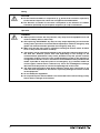
General instructions
Many of the diagrams and drawings in instruction manuals show the inverter without a cover, or
partially open. Never run the inverter in this status. Always replace the cover and follow this instruction manual when operating the inverter.
VI
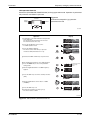
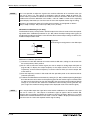
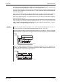
Symbols used in the manual
Use of instructions
Instructions concerning important information are marked separately and are displayed as follows:
NOTE
Text of instruction
Use of examples
Examples are marked separately and are displayed as follows:
Example 쑴
Example text
쑶
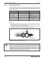
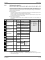
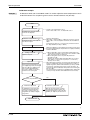
Use of numbering in the figures
Numbering within the figures is displayed by white numbers within black circles and is explained
in a table following it using the same number, e.g.:
Use of handling instructions
Handling instructions are steps that must be carried out in their exact sequence during startup,
operation, maintenance and similar operations.
They are numbered consecutively (black numbers in white circles):
Text.
Text.
Text.
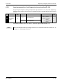
Use of footnotes in tables
Instructions in tables are explained in footnotes underneath the tables (in superscript). There is
a footnote character at the appropriate position in the table (in superscript).
If there are several footnotes for one table then these are numbered consecutively underneath
the table (black numbers in white circle, in superscript):
�
Text
Text
� Text
�
FR-F700 EC
VII
VIII
Contents
Contents
1
Product Checking and Part Identification
1.1
Inverter Type . . . . . . . . . . . . . . . . . . . . . . . . . . . . . . . . . . . . . . . . . . . . . . . . . . . 1-1
1.2
Description of the Case . . . . . . . . . . . . . . . . . . . . . . . . . . . . . . . . . . . . . . . . . . . 1-2
1.2.1
Accessory . . . . . . . . . . . . . . . . . . . . . . . . . . . . . . . . . . . . . . . . . . . . . . .1-3
2
Installation
2.1
Removal and reinstallation of the operation panel . . . . . . . . . . . . . . . . . . . . . . .2-1
2.2
Removal and reinstallation of the front cover . . . . . . . . . . . . . . . . . . . . . . . . . . . 2-2
2.2.1
FR-F740-00023 to 00620-EC . . . . . . . . . . . . . . . . . . . . . . . . . . . . . . . . 2-2
2.2.2
FR-F740-00770 to 12120-EC . . . . . . . . . . . . . . . . . . . . . . . . . . . . . . . . 2-3
2.2.3
FR-F746-00023 to 01160-EC . . . . . . . . . . . . . . . . . . . . . . . . . . . . . . . . 2-5
2.3
Mounting. . . . . . . . . . . . . . . . . . . . . . . . . . . . . . . . . . . . . . . . . . . . . . . . . . . . . . . 2-6
2.4
Enclosure design . . . . . . . . . . . . . . . . . . . . . . . . . . . . . . . . . . . . . . . . . . . . . . . . 2-7
2.4.1
Inverter installation environment . . . . . . . . . . . . . . . . . . . . . . . . . . . . . . 2-7
2.4.2
Inverter placement . . . . . . . . . . . . . . . . . . . . . . . . . . . . . . . . . . . . . . . 2-11
2.4.3
Heatsink protrusion attachment (FR-A7CN) . . . . . . . . . . . . . . . . . . . .2-13
3
Wiring
3.1
Inverter and peripheral devices . . . . . . . . . . . . . . . . . . . . . . . . . . . . . . . . . . . . .3-1
3.1.1
Peripheral devices. . . . . . . . . . . . . . . . . . . . . . . . . . . . . . . . . . . . . . . . .3-3
3.2
Terminal connection diagram . . . . . . . . . . . . . . . . . . . . . . . . . . . . . . . . . . . . . . .3-5
3.3
Main circuit connection . . . . . . . . . . . . . . . . . . . . . . . . . . . . . . . . . . . . . . . . . . . .3-7
3.4
3.3.1
Specification of main circuit terminal . . . . . . . . . . . . . . . . . . . . . . . . . . . 3-7
3.3.2
Terminal layout and wiring . . . . . . . . . . . . . . . . . . . . . . . . . . . . . . . . . .3-7
Control circuit specifications . . . . . . . . . . . . . . . . . . . . . . . . . . . . . . . . . . . . . . . 3-15
3.4.1
Control circuit terminals. . . . . . . . . . . . . . . . . . . . . . . . . . . . . . . . . . . . 3-19
3.4.2
Wiring instructions . . . . . . . . . . . . . . . . . . . . . . . . . . . . . . . . . . . . . . . .3-21
3.4.3
Separate power supply for the control circuit . . . . . . . . . . . . . . . . . . . 3-22
3.4.4
Changing the control logic. . . . . . . . . . . . . . . . . . . . . . . . . . . . . . . . . . 3-25
3.5
Connecting the operation panel using a connection cable . . . . . . . . . . . . . . . .3-28
3.6
RS-485 terminal block . . . . . . . . . . . . . . . . . . . . . . . . . . . . . . . . . . . . . . . . . . . 3-29
3.6.1
FR-F700 EC
Communication operation . . . . . . . . . . . . . . . . . . . . . . . . . . . . . . . . . . 3-30
IX
Contents
3.7
3.8
X
Connection of stand-alone option units . . . . . . . . . . . . . . . . . . . . . . . . . . . . . .3-31
3.7.1
Magnetic contactors (MC) . . . . . . . . . . . . . . . . . . . . . . . . . . . . . . . . . . 3-31
3.7.2
Connection of a brake unit (FR-BU/MT-BU5) . . . . . . . . . . . . . . . . . . . 3-33
3.7.3
Connection of the high power factor converter (FR-HC, MT-HC) . . . . 3-36
3.7.4
Connection of the power regeneration common converter FR-CV
(01160 or less) . . . . . . . . . . . . . . . . . . . . . . . . . . . . . . . . . . . . . . . . . . 3-38
3.7.5
Connection of power regeneration converter (MT-RC)
(01800 or more) . . . . . . . . . . . . . . . . . . . . . . . . . . . . . . . . . . . . . . . . .3-39
3.7.6
Connection of the power improving DC reactor (FR-HEL) . . . . . . . . .3-40
3.7.7
Installation of a reactor . . . . . . . . . . . . . . . . . . . . . . . . . . . . . . . . . . . .3-40
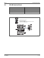
Electromagnetic compatibility (EMC) . . . . . . . . . . . . . . . . . . . . . . . . . . . . . . . . 3-41
3.8.1
Leakage currents and countermeasures. . . . . . . . . . . . . . . . . . . . . . . 3-41
3.8.2
Inverter-generated noises and their reduction techniques . . . . . . . . .3-46
3.8.3
EMC filter . . . . . . . . . . . . . . . . . . . . . . . . . . . . . . . . . . . . . . . . . . . . . .3-49
3.8.4
Power supply harmonics . . . . . . . . . . . . . . . . . . . . . . . . . . . . . . . . . . .3-50
3.8.5
Inverter-driven 400V class motor . . . . . . . . . . . . . . . . . . . . . . . . . . . .3-51
4
Operation
4.1
Precautions for use of the inverter . . . . . . . . . . . . . . . . . . . . . . . . . . . . . . . . . . . 4-1
4.2
Drive the motor . . . . . . . . . . . . . . . . . . . . . . . . . . . . . . . . . . . . . . . . . . . . . . . . . . 4-3
4.3
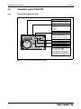
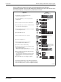
Operation panel FR-DU07 . . . . . . . . . . . . . . . . . . . . . . . . . . . . . . . . . . . . . . . . . 4-4
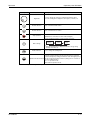
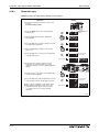
4.3.1
Parts of the operation panel . . . . . . . . . . . . . . . . . . . . . . . . . . . . . . . . . 4-4
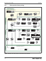
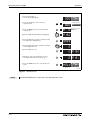
4.3.2
Basic operation (factory setting) . . . . . . . . . . . . . . . . . . . . . . . . . . . . . . 4-6
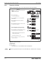
4.3.3
Operation lock . . . . . . . . . . . . . . . . . . . . . . . . . . . . . . . . . . . . . . . . . . . .4-7
4.3.4
Monitoring of output current and output voltage . . . . . . . . . . . . . . . . . .4-9
4.3.5
First priority monitor . . . . . . . . . . . . . . . . . . . . . . . . . . . . . . . . . . . . . . .4-9
4.3.6
Digital dial push . . . . . . . . . . . . . . . . . . . . . . . . . . . . . . . . . . . . . . . . . . . 4-9
4.4
Overheat protection of the motor by the inverter . . . . . . . . . . . . . . . . . . . . . . .4-10
4.5
PU operation mode. . . . . . . . . . . . . . . . . . . . . . . . . . . . . . . . . . . . . . . . . . . . . . 4-12
4.5.1
Set the set frequency to operate . . . . . . . . . . . . . . . . . . . . . . . . . . . . . 4-13
4.5.2
Use the digital dial like a potentiometer to perform operation . . . . . . . 4-14
4.5.3
Use switches to give the frequency command (multi-speed setting) .4-15
4.5.4
Perform frequency setting by analog voltage input . . . . . . . . . . . . . . . 4-18
4.5.5
Perform frequency setting by analog current input . . . . . . . . . . . . . . . 4-20
Contents
4.6
External operation . . . . . . . . . . . . . . . . . . . . . . . . . . . . . . . . . . . . . . . . . . . . . .4-22
4.6.1
Use the set frequency set by the operation panel (Pr. 79 = 3) . . . . . . 4-22
4.6.2
Use switches to give a start command and a frequency command
(multi-speed setting) (Pr. 4 to Pr. 6) . . . . . . . . . . . . . . . . . . . . . . . . . . 4-24
4.6.3
Perform frequency setting by analog voltage input . . . . . . . . . . . . . . . 4-27
4.6.4
Change the frequency (50Hz) of the maximum value
of potentiometer (at 5V) . . . . . . . . . . . . . . . . . . . . . . . . . . . . . . . . . . . 4-30
4.6.5
Perform frequency setting by analog current input . . . . . . . . . . . . . . . 4-31
4.6.6
Change the frequency (50Hz) of the maximum value
of potentiometer (at 20mA) . . . . . . . . . . . . . . . . . . . . . . . . . . . . . . . . . 4-33
5
Basic settings
5.1
Simple mode parameter list . . . . . . . . . . . . . . . . . . . . . . . . . . . . . . . . . . . . . . . . 5-1
5.2
Increase the starting torque (Pr. 0). . . . . . . . . . . . . . . . . . . . . . . . . . . . . . . . . . . 5-3
5.3
Limit the maximum and minimum output frequency (Pr. 1, Pr. 2) . . . . . . . . . . . 5-5
5.4
When the rated motor frequency is 60Hz (Pr. 3) . . . . . . . . . . . . . . . . . . . . . . . .5-7
5.5
Change the acceleration/deceleration time (Pr. 7, Pr. 8) . . . . . . . . . . . . . . . . . .5-8
5.6
Energy saving operation (Pr. 60) . . . . . . . . . . . . . . . . . . . . . . . . . . . . . . . . . . . 5-10
5.7
Operation mode (Pr. 79). . . . . . . . . . . . . . . . . . . . . . . . . . . . . . . . . . . . . . . . . . 5-12
5.8
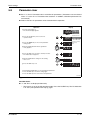
Parameter clear . . . . . . . . . . . . . . . . . . . . . . . . . . . . . . . . . . . . . . . . . . . . . . . . 5-13
5.9
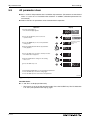
All parameter clear . . . . . . . . . . . . . . . . . . . . . . . . . . . . . . . . . . . . . . . . . . . . . . 5-14
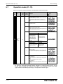
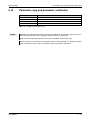
5.10
Parameter copy and parameter verification . . . . . . . . . . . . . . . . . . . . . . . . . . . 5-15
5.10.1 Parameter copy . . . . . . . . . . . . . . . . . . . . . . . . . . . . . . . . . . . . . . . . . . 5-16
5.10.2 Parameter verification . . . . . . . . . . . . . . . . . . . . . . . . . . . . . . . . . . . . .5-18
6
Parameter
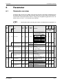
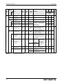
6.1
Parameter overview . . . . . . . . . . . . . . . . . . . . . . . . . . . . . . . . . . . . . . . . . . . . . . 6-1
6.2
Motor torque . . . . . . . . . . . . . . . . . . . . . . . . . . . . . . . . . . . . . . . . . . . . . . . . . . .6-30
6.3
FR-F700 EC
6.2.1
Manual torque boost (Pr. 0, Pr. 46) . . . . . . . . . . . . . . . . . . . . . . . . . . .6-30
6.2.2
Simple magnetic flux vector control (Pr. 80, Pr. 90) . . . . . . . . . . . . . . 6-33
6.2.3
Slip compensation (Pr. 245 to Pr. 247) . . . . . . . . . . . . . . . . . . . . . . . .6-34
6.2.4
Stall prevention operation (Pr. 22, Pr. 23, Pr. 48, Pr. 49, Pr. 66,
Pr. 148, Pr. 149, Pr. 154, Pr. 156, Pr. 157) . . . . . . . . . . . . . . . . . . . . . 6-35
6.2.5
Multiple rating (LD = Light Duty, SLD = Super Light Duty) (Pr. 570). . 6-44
Limit the output frequency . . . . . . . . . . . . . . . . . . . . . . . . . . . . . . . . . . . . . . . . 6-45
6.3.1
Maximum and minimum frequency (Pr. 1, Pr. 2, Pr. 18) . . . . . . . . . . .6-45
6.3.2
Avoid mechanical resonance points (Frequency jump)
(Pr. 31 to Pr. 36) . . . . . . . . . . . . . . . . . . . . . . . . . . . . . . . . . . . . . . . . .6-47
XI
Contents
6.4
6.5
6.6
6.7
6.8
6.9
XII
Set V/f pattern. . . . . . . . . . . . . . . . . . . . . . . . . . . . . . . . . . . . . . . . . . . . . . . . . . 6-49
6.4.1
Base frequency, voltage (Pr. 3, Pr. 19, Pr. 47) . . . . . . . . . . . . . . . . . . 6-49
6.4.2
Load pattern selection (Pr. 14) . . . . . . . . . . . . . . . . . . . . . . . . . . . . . .6-51
6.4.3
Adjustable 5 points V/f (Pr. 71, Pr. 100 to Pr. 109) . . . . . . . . . . . . . . . 6-52
Frequency setting by external terminals. . . . . . . . . . . . . . . . . . . . . . . . . . . . . .6-54
6.5.1
Multi-speed setting operation
(Pr. 4 to Pr. 6, Pr. 24 to Pr. 27, Pr. 232 to Pr. 239) . . . . . . . . . . . . . . . 6-54
6.5.2
Jog operation (Pr. 15, Pr. 16) . . . . . . . . . . . . . . . . . . . . . . . . . . . . . . . 6-57
6.5.3
Input compensation of multi-speed and remote setting (Pr. 28) . . . . . 6-61
6.5.4
Remote setting function (Pr. 59) . . . . . . . . . . . . . . . . . . . . . . . . . . . . . 6-62
Acceleration and deceleration . . . . . . . . . . . . . . . . . . . . . . . . . . . . . . . . . . . . . 6-66
6.6.1
Acceleration and deceleration time
(Pr. 7, Pr. 8, Pr. 20, Pr. 21, Pr. 44, Pr. 45) . . . . . . . . . . . . . . . . . . . . . 6-66
6.6.2
Starting frequency and start-time hold function (Pr. 13, Pr. 571) . . . .6-70
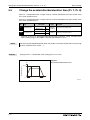
6.6.3
Acceleration and deceleration pattern (Pr. 29, Pr. 140 to Pr. 143) . . .6-72
Selection and protection of a motor . . . . . . . . . . . . . . . . . . . . . . . . . . . . . . . . .6-76
6.7.1
Motor protection from overheat (Electronic thermal relay function)
(Pr. 9, Pr. 51). . . . . . . . . . . . . . . . . . . . . . . . . . . . . . . . . . . . . . . . . . . . 6-76
6.7.2
Applied motor (Pr. 71) . . . . . . . . . . . . . . . . . . . . . . . . . . . . . . . . . . . . .6-82
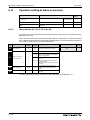
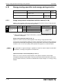
Motor brake and stop operation . . . . . . . . . . . . . . . . . . . . . . . . . . . . . . . . . . . .6-83
6.8.1
DC injection brake (Pr. 10 to Pr. 12) . . . . . . . . . . . . . . . . . . . . . . . . . . 6-83
6.8.2
Selection of a regenerative brake (Pr. 30, Pr. 70) . . . . . . . . . . . . . . . .6-86
6.8.3
Stop selection (Pr. 250). . . . . . . . . . . . . . . . . . . . . . . . . . . . . . . . . . . . 6-92
6.8.4
Output stop function (Pr. 522) . . . . . . . . . . . . . . . . . . . . . . . . . . . . . . . 6-94
Function assignment of external terminals . . . . . . . . . . . . . . . . . . . . . . . . . . . . 6-96
6.9.1
Input terminal function selection (Pr. 178 to Pr. 189) . . . . . . . . . . . . . 6-96
6.9.2
Inverter output shutoff signal (MRS signal, Pr. 17) . . . . . . . . . . . . . . . 6-99
6.9.3
Operation condition selection of second function selection signal
(Terminal RT, Pr. 155) . . . . . . . . . . . . . . . . . . . . . . . . . . . . . . . . . . .6-101
6.9.4
Start signal selection (Terminal STF, STR, STOP, Pr. 250) . . . . . . .6-103
6.9.5
Output terminal function selection (Pr. 190 to Pr. 196) . . . . . . . . . . .6-107
6.9.6
Detection of output frequency
(SU, FU, FU2, Pr. 41 to Pr. 43, Pr. 50) . . . . . . . . . . . . . . . . . . . . . . .6-113
6.9.7
Output current detection function
(Y12, Y13, Pr. 150 to Pr. 153, Pr. 166, Pr. 167) . . . . . . . . . . . . . . . .6-115
6.9.8
Remote output function (REM, Pr. 495 to Pr. 497) . . . . . . . . . . . . . .6-118
6.9.9
Pulse train output of output power (Y79 signal, Pr. 799). . . . . . . . . .6-120
Contents
6.10
Monitor display and monitor output signals . . . . . . . . . . . . . . . . . . . . . . . . . .6-121
6.10.1 Speed display and speed setting (Pr. 37, Pr. 144) . . . . . . . . . . . . . .6-121
6.10.2 DU/PU monitor display selection (Pr. 52, Pr. 54, Pr. 158, Pr. 170,
Pr. 171, Pr. 268, Pr. 563, Pr. 564, Pr. 891) . . . . . . . . . . . . . . . . . . . .6-123
6.10.3 CA, AM terminal function selection (Pr. 55, Pr. 56, Pr. 867, Pr. 869) . . .6-130
6.10.4 Terminal CA, AM calibration
[C0 (Pr. 900), C1 (Pr. 901), C8 (Pr. 930) to C11 (Pr. 931)] . . . . . . . .6-132
6.11
Operation selection at power failure . . . . . . . . . . . . . . . . . . . . . . . . . . . . . . . .6-137
6.11.1 Automatic restart
(Pr. 57, Pr. 58, Pr. 162 to Pr. 165, Pr. 299, Pr. 611) . . . . . . . . . . . . .6-137
6.11.2 Power failure-time deceleration-to-stop function
(Pr. 261 to Pr. 266) . . . . . . . . . . . . . . . . . . . . . . . . . . . . . . . . . . . . . .6-145
6.12
Operation setting at alarm occurrence . . . . . . . . . . . . . . . . . . . . . . . . . . . . . .6-152
6.12.1 Retry function (Pr. 65, Pr. 67 to Pr. 69) . . . . . . . . . . . . . . . . . . . . . . .6-152
6.12.2 Alarm code output selection (Pr. 76) . . . . . . . . . . . . . . . . . . . . . . . . .6-155
6.12.3 Input/output phase loss protection selection (Pr. 251, Pr. 872) . . . .6-157
6.13
Energy saving operation and energy saving monitor . . . . . . . . . . . . . . . . . . .6-158
6.13.1 Energy saving control and optimum excitation control (Pr. 60) . . . . .6-158
6.13.2 Energy saving monitor (Pr. 52, Pr. 54, Pr. 158, Pr. 891 to Pr. 899) .6-160
6.14
Motor noise, noise reduction . . . . . . . . . . . . . . . . . . . . . . . . . . . . . . . . . . . . .6-167
6.14.1 PWM carrier frequency and Soft-PWM control
(Pr. 72, Pr. 240, Pr. 260) . . . . . . . . . . . . . . . . . . . . . . . . . . . . . . . . . .6-167
6.14.2 Speed smoothing control (Pr. 653, Pr. 654) . . . . . . . . . . . . . . . . . . .6-169
6.15
Frequency setting by analog input (terminals 1, 2 and 4). . . . . . . . . . . . . . . .6-170
6.15.1 Analog input selection (Pr. 73, Pr. 267) . . . . . . . . . . . . . . . . . . . . . .6-170
6.15.2 Analog input compensation
(Pr. 73, Pr. 242, Pr. 243, Pr. 252, Pr. 253) . . . . . . . . . . . . . . . . . . . .6-177
6.15.3 Input filter time constant (Pr. 74) . . . . . . . . . . . . . . . . . . . . . . . . . . . .6-180
6.15.4 Bias and gain of frequency setting voltage (current)
[Pr. 125, Pr. 126, Pr. 241, C2 (Pr. 902) to C7 (Pr. 905)] . . . . . . . . . .6-181
6.15.5 4mA input check of current input (Pr. 573) . . . . . . . . . . . . . . . . . . . .6-189
6.16
Misoperation prevention and parameter setting restriction. . . . . . . . . . . . . . .6-192
6.16.1 Reset selection/disconnected PU detection/PU stop selection
(Pr. 75) . . . . . . . . . . . . . . . . . . . . . . . . . . . . . . . . . . . . . . . . . . . . . . .6-192
6.16.2 Parameter write selection (Pr. 77). . . . . . . . . . . . . . . . . . . . . . . . . . .6-197
6.16.3 Reverse rotation prevention selection (Pr. 78) . . . . . . . . . . . . . . . . .6-199
6.16.4 User groups (Pr. 160, Pr. 172 to Pr. 174) . . . . . . . . . . . . . . . . . . . . .6-200
6.17
Selection of operation mode and operation location . . . . . . . . . . . . . . . . . . .6-203
6.17.1 Operation mode selection (Pr. 79) . . . . . . . . . . . . . . . . . . . . . . . . . .6-203
6.17.2 Operation mode at power on (Pr. 79, Pr. 340) . . . . . . . . . . . . . . . . .6-215
6.17.3 Operation command source and speed command source during
communication operation (Pr. 338, Pr. 339, Pr. 550, Pr. 551) . . . . .6-217
FR-F700 EC
XIII
Contents
6.18
Communication operation and setting . . . . . . . . . . . . . . . . . . . . . . . . . . . . . .6-225
6.18.1 PU connector . . . . . . . . . . . . . . . . . . . . . . . . . . . . . . . . . . . . . . . . . .6-225
6.18.2 RS-485 terminals . . . . . . . . . . . . . . . . . . . . . . . . . . . . . . . . . . . . . . .6-228
6.18.3 Initial settings and specifications of RS-485 communication
(Pr. 117 to Pr. 124, Pr. 331 to Pr. 337, Pr. 341, Pr. 549) . . . . . . . . .6-233
6.18.4 Communication E²PROM write selection (Pr. 342) . . . . . . . . . . . . . .6-235
6.18.5 Mitsubishi inverter protocol (computer link communication) . . . . . . .6-236
6.18.6 Modbus-RTU communication
(Pr. 331, Pr. 332, Pr. 334, Pr. 343, Pr. 539, Pr. 549) . . . . . . . . . . . .6-253
6.19
Special operation . . . . . . . . . . . . . . . . . . . . . . . . . . . . . . . . . . . . . . . . . . . . . .6-271
6.19.1 PID control (Pr. 127 to Pr. 134, Pr. 241, Pr. 553,
Pr. 554, Pr. 575 to Pr. 577, C42 (Pr. 934) to C45 (Pr. 935)) . . . . . . .6-271
6.19.2 Commercial power supply-inverter switchover function
(Pr. 135 to Pr. 139, Pr. 159) . . . . . . . . . . . . . . . . . . . . . . . . . . . . . . .6-290
6.19.3 Advanced PID function (pump function)
(Pr. 554, Pr. 575 to Pr. 591) . . . . . . . . . . . . . . . . . . . . . . . . . . . . . . .6-296
6.19.4 Traverse function (Pr. 592 to Pr. 597) . . . . . . . . . . . . . . . . . . . . . . . .6-310
6.19.5 Regeneration avoidance function (Pr. 882 to Pr. 886) . . . . . . . . . . .6-313
6.20
Useful functions . . . . . . . . . . . . . . . . . . . . . . . . . . . . . . . . . . . . . . . . . . . . . . .6-316
6.20.1 Cooling fan operation selection (Pr. 244) . . . . . . . . . . . . . . . . . . . . .6-316
6.20.2 Display of the life of the inverter parts (Pr. 255 to Pr. 259) . . . . . . . .6-317
6.20.3 Maintenance timer alarm (Pr. 503, Pr. 504) . . . . . . . . . . . . . . . . . . .6-321
6.20.4 Current average value monitor signal (Pr. 555 to Pr. 557) . . . . . . . .6-322
6.20.5 Free parameters (Pr. 888, Pr. 889) . . . . . . . . . . . . . . . . . . . . . . . . . .6-326
6.21
Setting for the parameter unit, operation panel . . . . . . . . . . . . . . . . . . . . . . .6-327
6.21.1 PU display language selection (Pr. 145) . . . . . . . . . . . . . . . . . . . . . .6-327
6.21.2 Operation panel frequency setting/key lock operation selection
(Pr. 161) . . . . . . . . . . . . . . . . . . . . . . . . . . . . . . . . . . . . . . . . . . . . . .6-328
6.21.3 Buzzer control (Pr. 990) . . . . . . . . . . . . . . . . . . . . . . . . . . . . . . . . . .6-328
6.21.4 PU contrast adjustment (Pr. 991) . . . . . . . . . . . . . . . . . . . . . . . . . . .6-329
XIV
7
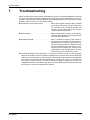
Troubleshooting
7.1
List of alarm display . . . . . . . . . . . . . . . . . . . . . . . . . . . . . . . . . . . . . . . . . . . . . . 7-2
7.2
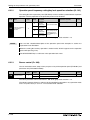
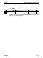
Causes and corrective actions . . . . . . . . . . . . . . . . . . . . . . . . . . . . . . . . . . . . . .7-4
7.3
Reset method of protective function . . . . . . . . . . . . . . . . . . . . . . . . . . . . . . . . . 7-19
7.4
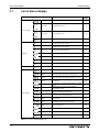
LED display . . . . . . . . . . . . . . . . . . . . . . . . . . . . . . . . . . . . . . . . . . . . . . . . . . .7-20
7.5
Check and clear of the alarm history . . . . . . . . . . . . . . . . . . . . . . . . . . . . . . . . 7-21
Contents
7.6
Check first when you have troubles . . . . . . . . . . . . . . . . . . . . . . . . . . . . . . . . .7-23
7.6.1
Motor does not start . . . . . . . . . . . . . . . . . . . . . . . . . . . . . . . . . . . . . .7-23
7.6.2
Motor or machine is making abnormal acoustic noise . . . . . . . . . . . .7-25
7.6.3
Inverter generates abnormal noise . . . . . . . . . . . . . . . . . . . . . . . . . . .7-25
7.6.4
Motor generates heat abnormally . . . . . . . . . . . . . . . . . . . . . . . . . . . . 7-25
7.6.5
Motor rotates in the opposite direction . . . . . . . . . . . . . . . . . . . . . . . . 7-26
7.6.6
Speed greatly differs from the setting . . . . . . . . . . . . . . . . . . . . . . . . . 7-26
7.6.7
Acceleration/deceleration is not smooth . . . . . . . . . . . . . . . . . . . . . . . 7-26
7.6.8
Speed varies during operation . . . . . . . . . . . . . . . . . . . . . . . . . . . . . .7-27
7.6.9
Operation mode is not changed properly . . . . . . . . . . . . . . . . . . . . . .7-27
7.6.10 Operation panel (FR-DU07) display is not operating . . . . . . . . . . . . . 7-28
7.6.11 Motor current is too large . . . . . . . . . . . . . . . . . . . . . . . . . . . . . . . . . . 7-28
7.6.12 Speed does not accelerate . . . . . . . . . . . . . . . . . . . . . . . . . . . . . . . . . 7-29
7.6.13 Unable to write parameter setting . . . . . . . . . . . . . . . . . . . . . . . . . . . . 7-30
7.6.14 Power lamp is not lit . . . . . . . . . . . . . . . . . . . . . . . . . . . . . . . . . . . . . .7-30
7.7
Meters and measuring methods . . . . . . . . . . . . . . . . . . . . . . . . . . . . . . . . . . . . 7-31
7.7.1
Measurement of powers . . . . . . . . . . . . . . . . . . . . . . . . . . . . . . . . . . . 7-32
7.7.2
Measurement of voltages and use of PT . . . . . . . . . . . . . . . . . . . . . .7-33
7.7.3
Measurement of currents . . . . . . . . . . . . . . . . . . . . . . . . . . . . . . . . . . 7-33
7.7.4
Use of CT and transducer . . . . . . . . . . . . . . . . . . . . . . . . . . . . . . . . . . 7-34
7.7.5
Measurement of inverter input power factor . . . . . . . . . . . . . . . . . . . .7-34
7.7.6
Measurement of converter output voltage
(across terminals P/+ and N/–) . . . . . . . . . . . . . . . . . . . . . . . . . . . . . .7-34
8
Maintenance and inspection
8.1
Inspection . . . . . . . . . . . . . . . . . . . . . . . . . . . . . . . . . . . . . . . . . . . . . . . . . . . . . .8-1
8.2
FR-F700 EC
8.1.1
Daily inspection . . . . . . . . . . . . . . . . . . . . . . . . . . . . . . . . . . . . . . . . . . . 8-1
8.1.2
Periodic inspection . . . . . . . . . . . . . . . . . . . . . . . . . . . . . . . . . . . . . . . . 8-1
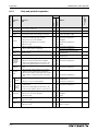
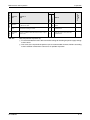
8.1.3
Daily and periodic inspection . . . . . . . . . . . . . . . . . . . . . . . . . . . . . . . . 8-2
8.1.4
Display of the life of the inverter parts . . . . . . . . . . . . . . . . . . . . . . . . . . 8-4
8.1.5
Checking the inverter and converter modules. . . . . . . . . . . . . . . . . . . .8-7
8.1.6
Cleaning . . . . . . . . . . . . . . . . . . . . . . . . . . . . . . . . . . . . . . . . . . . . . . . . 8-8
8.1.7
Replacement of parts . . . . . . . . . . . . . . . . . . . . . . . . . . . . . . . . . . . . . . 8-8
8.1.8
Inverter replacement . . . . . . . . . . . . . . . . . . . . . . . . . . . . . . . . . . . . . .8-16
Measurements on the main circuit . . . . . . . . . . . . . . . . . . . . . . . . . . . . . . . . . . 8-17
8.2.1
Insulation resistance test using megger . . . . . . . . . . . . . . . . . . . . . . .8-17
8.2.2
Pressure test . . . . . . . . . . . . . . . . . . . . . . . . . . . . . . . . . . . . . . . . . . . . 8-17
8.2.3
Measurement of voltages and currents . . . . . . . . . . . . . . . . . . . . . . . .8-18
XV
Contents
A
Appendix
A.1
Specifications FR-F740-00023 to -01160 . . . . . . . . . . . . . . . . . . . . . . . . . . . . A-1
A.2
Specifications FR-F740-01800 to -12120 . . . . . . . . . . . . . . . . . . . . . . . . . . . . A-2
A.3
Specifications FR-F746-00023 to -01160 . . . . . . . . . . . . . . . . . . . . . . . . . . . . A-3
A.4
Common specifications . . . . . . . . . . . . . . . . . . . . . . . . . . . . . . . . . . . . . . . . . . A-4
A.5
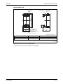
Outline dimension drawings . . . . . . . . . . . . . . . . . . . . . . . . . . . . . . . . . . . . . . A-6
A.5.1
FR-F740-00023 to -00126 . . . . . . . . . . . . . . . . . . . . . . . . . . . . . . . . . A-6
A.5.2
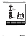
FR-F740-00170 to -00380 . . . . . . . . . . . . . . . . . . . . . . . . . . . . . . . . . A-7
A.5.3
FR-F740-00470 and -00620 . . . . . . . . . . . . . . . . . . . . . . . . . . . . . . . . A-8
A.5.4
FR-F740-00770 to -01160 . . . . . . . . . . . . . . . . . . . . . . . . . . . . . . . . . A-9
A.5.5
FR-F740-01800 . . . . . . . . . . . . . . . . . . . . . . . . . . . . . . . . . . . . . . . . A-10
A.5.6
FR-F740-02160 to -03610 . . . . . . . . . . . . . . . . . . . . . . . . . . . . . . . . A-11
A.5.7
FR-F740-04320 to -06830 . . . . . . . . . . . . . . . . . . . . . . . . . . . . . . . . A-12
A.5.8
FR-F740-07700 and -08660 . . . . . . . . . . . . . . . . . . . . . . . . . . . . . . . A-13
A.5.9
FR-F740-09620 to -12120 . . . . . . . . . . . . . . . . . . . . . . . . . . . . . . . . A-14
A.5.10 FR-F746-00023 to -00126 . . . . . . . . . . . . . . . . . . . . . . . . . . . . . . . . A-15
A.5.11 FR-F746-00170 and -00250 . . . . . . . . . . . . . . . . . . . . . . . . . . . . . . . A-15
A.5.12 FR-F746-00310 and -00380 . . . . . . . . . . . . . . . . . . . . . . . . . . . . . . . A-16
A.5.13 FR-F746-00470 and -00620 . . . . . . . . . . . . . . . . . . . . . . . . . . . . . . . A-16
A.5.14 FR-F746-00770 . . . . . . . . . . . . . . . . . . . . . . . . . . . . . . . . . . . . . . . . A-17
A.5.15 FR-F746-00930 and -01160 . . . . . . . . . . . . . . . . . . . . . . . . . . . . . . . A-17
A.5.16 DC reactors . . . . . . . . . . . . . . . . . . . . . . . . . . . . . . . . . . . . . . . . . . . A-18
A.5.17 Panel cutting for the heatsink protrusion attachment . . . . . . . . . . . . A-23
A.5.18 Operation panel FR-DU07 . . . . . . . . . . . . . . . . . . . . . . . . . . . . . . . . A-24
A.5.19 Parameter unit FR-PU07 . . . . . . . . . . . . . . . . . . . . . . . . . . . . . . . . . A-24
XVI
A.6
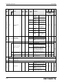
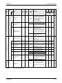
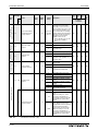
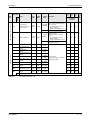
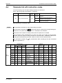
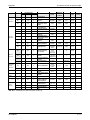
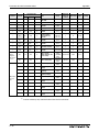
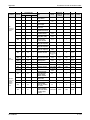
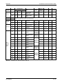
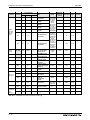
Parameter list with instruction codes . . . . . . . . . . . . . . . . . . . . . . . . . . . . . . . A-25
A.7
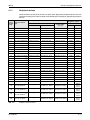
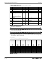
Specification change . . . . . . . . . . . . . . . . . . . . . . . . . . . . . . . . . . . . . . . . . . . A-40
A.7.1
SERIAL number check . . . . . . . . . . . . . . . . . . . . . . . . . . . . . . . . . . . A-40
A.7.2
Changed functions . . . . . . . . . . . . . . . . . . . . . . . . . . . . . . . . . . . . . . A-41
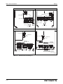
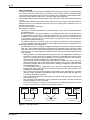
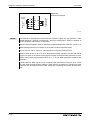
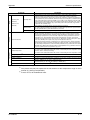
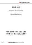
Product Checking and Part Identification
1
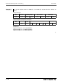
Inverter Type
Product Checking and Part Identification
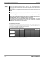
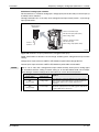
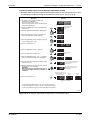
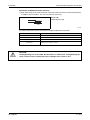
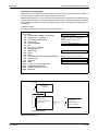
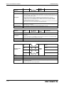
Unpack the inverter and check the capacity plate on the front cover and the rating plate on the
inverter side face to ensure that the product agrees with your order and the inverter is intact.
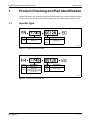
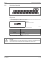
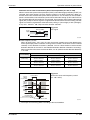
1.1
Inverter Type
Symbol
Voltage Class
Symbol
Type number
F740
Three-phase
400V class
00023
to
12120
5-digit display
I001331E
Fig. 1-1: Inverter Type FR-F740 EC
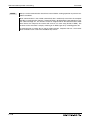
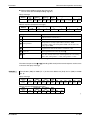
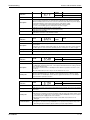
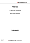
Symbol
Voltage Class
Symbol
Type number
00023
to
01160
5-digit display
F746
Three-phase
400V class
waterproof structure IP54
(standard IEC 60529: 2001)
specification
I001393E
Fig. 1-2: Inverter type FR-F746 EC
FR-F700 EC
1-1
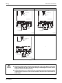
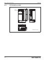
Description of the Case
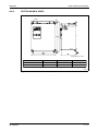
1.2
Product Checking and Part Identification
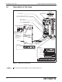
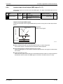
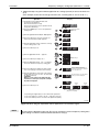
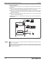
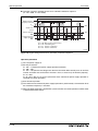
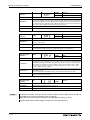
Description of the Case
Cooling fan
(refer to section 8.1.7)
PU connector
(refer to section 3.5)
RS-485 terminal
Connector for plug-in option connection
(Refer to the instruction manual of options)
AU/PTC-switchover
(refer to section 3.4)
Connector with/without EMC filter
(refer to section 3.8.3)
Operation panel FR-DU07
(refer to section 4.3)
POWER lamp
Lit when the control circuit
(R1/L11, S1/L21) is supplied
with power.
ALARM lamp
Lit when the inverter
is in the alarm status
(major fault)
(refer to chapter 7)
Main circuit
terminal block
(refer to section 3.3)
Control circuit
terminal block
(refer to
section 3.4)
Front cover
CHARGE lamp
Lit when power is
supplied to the
main circuit.
Comb shaped
wiring cover
(refer to section 2.3)
Capacity plate
Capacity plate
Rating plate
Inverter type
Serial number
Inverter type
Input rating
Output rating
Serial number
Overload current rating
Ambient temperature
I000990E
Fig. 1-3: Appearance and Structure
NOTE
1-2
For removal and reinstallation of covers, refer to section 2.2.
Product Checking and Part Identification
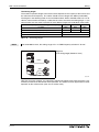
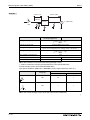
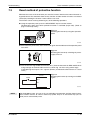
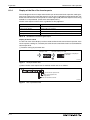
1.2.1
Description of the Case
Accessory
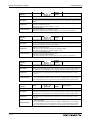
Fan cover fixing screws
Capacity
Screw Size[mm]
Number
00083/00126
M3 × 35
1
00170 to 00380
M4 × 40
2
00470/00620
M4 × 50
1
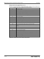
Tab. 1-1: Fan cover fixing screws
NOTES
The fan cover fixing screws are not delivered with models 00620 or less.
For removal and reinstallation of the cooling fans, refer to section 8.1.7.
DC reactor
For models 01800 or more the supplied DC reactor has to be installed.
FR-F700 EC
1-3
Description of the Case
1-4
Product Checking and Part Identification
Installation
2
E
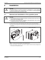
2.1
E
Removal and reinstallation of the operation panel
Installation
CAUTION:
Check that packing is not removed at removal or reinstallation of a cover. If packing
is removed, contact the sales representative. If the inverter is used with packing
removed, the inverter does not conform to IP54.
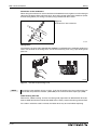
Removal and reinstallation of the operation panel
CAUTION:
● If the operation panel of the inverter FR-F746 is removed from the front cover, the
inverter does not conform to IP54.
● The operation panel (FR-DU07) is designed to IP54 specifications. Do not install
the FR-DU07 mounted on the FR-F740 EC.
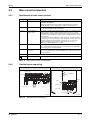
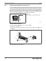
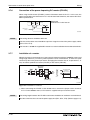
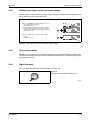
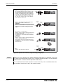
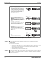
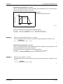
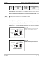
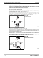
Loosen the two screws on the operation panel. (These screws cannot be removed.)
Push the left and right hooks of the operation panel and pull the operation panel toward you
to remove.
Loosen the screws
Remove operation panel
I000991E
Fig. 2-1: Removal and reinstallation of the operation panel
When reinstalling the operation panel, insert it straight to reinstall securely and tighten the
fixed screws of the operation panel.
FR-F700 EC
2-1
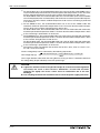
Removal and reinstallation of the front cover
Installation
2.2
Removal and reinstallation of the front cover
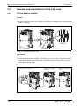
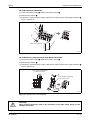
2.2.1
FR-F740-00023 to 00620-EC
Removal
Loosen the installation screws of the front cover.
Pull the front cover toward you to remove by pushing an installation hook using left fixed
hooks as supports.
Loosen the screws
Remove front cover
Installation hook
I000992E
Fig. 2-2: Removal of the front cover
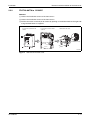
Reinstallation
Insert the two fixed hooks on the left side of the front cover into the sockets of the inverter.
Using the fixed hooks as supports, securely press the front cover against the inverter.
(Although installation can be done with the operation panel mounted, make sure that a
connector is securely fixed.)
Tighten the installation screws and fix the front cover.
Insert hooks into the sockets
Press front cover against
the inverter
Tighten the installation
screws
I000993E
Fig. 2-3: Reinstallation of the front cover
2-2
Installation
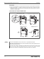
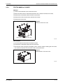
2.2.2
Removal and reinstallation of the front cover
FR-F740-00770 to 12120-EC
Removal
Loosen the installation screws of the front cover 1.
Loosen the installation screws of the front cover 2.
Pull the front cover 2 toward you to remove by pushing an installation hook on the right side
using left fixed hooks as supports.
Loosen the screw of front
cover 1
Loosen the screw of front
cover 2
Remove front cover
Installation hook
Cover 1
Cover 2
I000994E
Fig. 2-4: Removal of the front cover
FR-F700 EC
2-3
Removal and reinstallation of the front cover
Installation
Reinstallation
Insert the two fixed hooks on the left side of the front cover 2 into the sockets of the inverter.
Using the fixed hooks as supports, securely press the front cover 2 against the inverter.
(Although installation can be done with the operation panel mounted, make sure that a
connector is securely fixed.)
Fix the front cover 2 with the installation screws.
Fix the front cover 1 with the installation screws.
Insert hooks into the sockets
Fix front cover 2 with the
installation screws
Press front cover 2 against the inverter
Fix front cover 1 with the
installation screws
I000995E
Fig. 2-5: Reinstallation of the front cover
NOTES
For the FR-F740-04320 or more, the front cover 1 is separated into two parts.
Fully make sure that the front cover has been reinstalled securely. Always tighten the installation screws of the front cover.
The same serial number is printed on the capacity plate of the front cover and the rating
plate of the inverter. Before reinstalling the front cover, check the serial numbers to ensure
that the cover removed is reinstalled to the inverter from where it was removed.
2-4
Installation
2.2.3
Removal and reinstallation of the front cover
FR-F746-00023 to 01160-EC
Removal
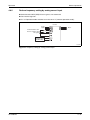
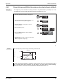
Loosen the installation screw of the front cover.
Since the metal chain is mounted to the front cover, remove the front cover slowly.
Remove the connection cable from the PU connector.
Remove the hook of metal chain end from the inverter.
Remove the front cover.
Removal/installation
hook
Metal chain
Fig. 2-6:
Removal of the front cover
Connection cable
I001394E
Reinstallation
Install the hook of metal chain end to the inverter.
Connect the connection cable to the PU connector.
Fix the front cover using the installation screws securely. When installing the front cover,
be careful not to pinch the connection cable or the metal chain.
Fig. 2-7:
Reinstallation of the front cover
I001395E
FR-F700 EC
2-5
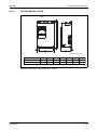
Mounting
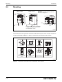
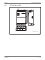
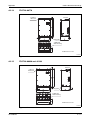
2.3
Installation
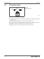
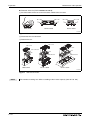
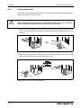
Mounting
00023 to 00620
00770 to 12120
CAUTION:
When encasing multiple inverters, follow the
instructions on page 2-11.
Refer to Fig.
2-10:
Fix six positions for the FR-F740-04320
to 08660 and fix eight positions for the
FR-F740-09620 to 12120.
I000997E
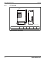
Fig. 2-8: Installation on the panel
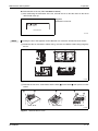
The inverter consists of precision mechanical and electronic parts. Never install or handle it in
any of the following conditions as doing so could cause an operation fault or failure.
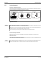
Direct sunlight
Vertical mounting
(When installing two or more
inverters, install them in
parallel.)
Vibration (≥ 5,9 m/s²)
(≥ 2.9m/s² for the 04320 or more)
Transportation by holding
the front cover
High temperature,
high humidity
Oil mist, flammable gas,
corrosive gas, fluff, dust, etc.
Horizontal placement
Mounting to combustible
material
I000998E
Fig. 2-9: Conditions, that could cause an operation fault or failure
2-6
Installation
2.4
Enclosure design
Enclosure design
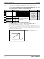
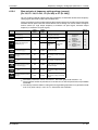
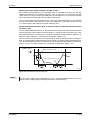
When an inverter enclosure is to be designed and manufactured, heat generated by contained
equipment, etc., the environment of an operating place, and others must be fully considered to
determine the enclosure structure, size and equipment layout. The inverter unit uses many
semiconductor devices. To ensure higher reliability and long period of operation, operate the inverter in the ambient environment that completely satisfies the equipment specifications.
2.4.1
Inverter installation environment
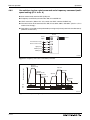
As the inverter installation environment should satisfy the standard specifications indicated in
the following table, operation in any place that does not meet these conditions not only deteriorates the performance and life of the inverter, but also causes a failure. Refer to the following
points and take adequate measures.
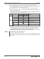
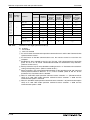
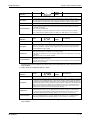
Item
Ambient
temperature
FR-F740
FR-F746
150 % overload
capacity
−10 °C to +50°C
(non-freezing)
−10°C to +40°C
(non-freezing)
120 % overload
capacity (Initial setting)
−10 °C to +40°C
(non-freezing)
−10°C to +30°C
(non-freezing)
Ambient humidity
90% RH or less (non-condensing)
Atmosphere
Free from corrosive and explosive gases, dust and dirt
Maximum altitude
1000m or less
Vibration
5.9m/s² or less (2.9m/s² or less for the 04320 or more)
at 10 to 55Hz (directions of X, Y, Z axes)
Tab. 2-1: Environmental standard specifications of inverter
Temperature
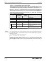
The permissible ambient temperature of the inverter FR-F740 is between −10 and +50°C (when
LD is set) or −10 and +40°C (when SLD is set) and of the inverter FR-F746 is between −10 and
+40°C (when LD is set) or −10 and +30°C (when SLD is set). Always operate the inverter within
this temperature range. Operation outside this range will considerably shorten the service lives
of the semiconductors, parts, capacitors and others. Take the following measures so that the
ambient temperature of the inverter falls within the specified range.
● Measures against high temperature
– Use a forced ventilation system or similar cooling system. (Refer to page 2-10.)
– Install the enclosure in an air-conditioned electrical chamber.
– Block direct sunlight.
– Provide a shield or similar plate to avoid direct exposure to the radiated heat and wind
of a heat source.
– Ventilate the area around the enclosure well.
● Measures against low temperature
– Provide a space heater in the enclosure.
– Do not power off the inverter. (Keep the start signal of the inverter off.)
● Sudden temperature changes
– Select an installation place where temperature does not change suddenly.
– Avoid installing the inverter near the air outlet of an air conditioner.
– If temperature changes are caused by opening/closing of a door, install the inverter away
from the door.
FR-F700 EC
2-7
Enclosure design
Installation
Humidity
Normally operate the inverter within the 45 to 90% range of the ambient humidity. Too high humidity will pose problems of reduced insulation and metal corrosion. On the other hand, too low
humidity may produce a spatial electrical breakdown. The insulation distance specified in
JEM1103 "Control Equipment Insulator" is defined as humidity 45 to 85%.
● Measures against high humidity
– Make the enclosure enclosed, and provide it with a hygroscopic agent.
– Take dry air into the enclosure from outside.
– Provide a space heater in the enclosure.
● Measures against low humidity
What is important in fitting or inspection of the unit in this status is to discharge your body
(static electricity) beforehand and keep your body from contact with the parts and patterns,
besides blowing air of proper humidity into the enclosure from outside.
● Measures against condensation
Condensation may occur if frequent operation stops change the in-enclosure temperature
suddenly or if the outside air temperature changes suddenly. Condensation causes such
faults as reduced insulation and corrosion.
– Take the measures against high humidity.
– Do not power off the inverter. (Keep the start signal of the inverter off.)
Dust, dirt, oil mist
Dust and dirt will cause such faults as poor contact of contact points, reduced insulation or reduced cooling effect due to moisture absorption of accumulated dust and dirt, and in-enclosure
temperature rise due to clogged filter.
In the atmosphere where conductive powder floats, dust and dirt will cause such faults as malfunction, deteriorated insulation and short circuit in a short time.
Since oil mist will cause similar conditions, it is necessary to take adequate measures.
● Measures against dust, dirt, oil mist
– Place in a totally enclosed enclosure.
Take measures if the in-enclosure temperature rises. (Refer to page 2-10.)
– Purge air.
Pump clean air from outside to make the in-enclosure pressure higher than the outsideair pressure.
Corrosive gas, salt damage
If the inverter is exposed to corrosive gas or to salt near a beach, the printed board patterns and
parts will corrode or the relays and switches will result in poor contact. In such places, take the
measures against dust, dirt, oil mist.
2-8
Installation
Enclosure design
Explosive, flammable gases
As the inverter is non-explosion proof, it must be contained in an explosion proof enclosure.
In places where explosion may be caused by explosive gas, dust or dirt, an enclosure cannot be
used unless it structurally complies with the guidelines and has passed the specified tests. This
makes the enclosure itself expensive (including the test charges).
The best way is to avoid installation in such places and install the inverter in a non-hazardous
place.
Highland
Use the inverter at the altitude of within 1000m.
If it is used at a higher place, it is likely that thin air will reduce the cooling effect and low air pressure will deteriorate dielectric strength.
Vibration, impact
The vibration resistance of the inverter is up to 5.9m/s² (2.9m/s² for the 04320 or more) at 10 to
55Hz frequency and 1mm amplitude for the directions of X, Y, Z axes.
Vibration or impact, if less than the specified value, applied for a long time may make the mechanism loose or cause poor contact to the connectors.
Especially when impact is imposed repeatedly, caution must be taken as the part pins are likely
to break.
● Countermeasures
– Provide the enclosure with rubber vibration isolators.
– Strengthen the structure to prevent the enclosure from resonance.
– Install the enclosure away from sources of vibration.
FR-F700 EC
2-9
Enclosure design
Installation
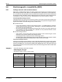
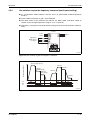
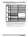
Cooling system types for inverter enclosure
From the enclosure that contains the inverter, the heat of the inverter and other equipment
(transformers, lamps, resistors, etc.) and the incoming heat such as direct sunlight must be dissipated to keep the in-enclosure temperature lower than the permissible temperatures of the inenclosure equipment including the inverter.
The cooling systems are classified as follows in terms of the cooling calculation method.
● Cooling by natural heat dissipation from the enclosure surface (Totally enclosed type)
● Cooling by heat sink (Aluminium fin, etc.)
● Cooling by ventilation (Forced ventilation type, pipe ventilation type)
● Cooling by heat exchanger or cooler (Heat pipe, cooler, etc.)
Cooling System
Natural
cooling
Enclosure Structure
Comment
Low in cost and generally used, but the enclosure
size increases as the inverter capacity increases.
For relatively small capacities.
Natural ventilation
(Enclosed, open type)
I001000E
Being a totally enclosed type, the most appropriate
for hostile environment having dust, dirt, oil mist,
etc. The enclosure size increases depending on the
inverter capacity.
Natural ventilation
(Totally enclosed
type)
I001001E
Forced
cooling
Having restrictions on the heatsink mounting position and area, and designed for relative small
capacities.
Heatsink cooling
heatsink
I001002E
For general indoor installation. Appropriate for
enclosure downsizing and cost reduction, and often
used.
Forced ventilation
I001003E
Heat pipe
heat pipe
Totally enclosed type for enclosure downsizing.
I001004E
Tab. 2-2: Cooling system types for inverter enclosure
2 - 10
Installation
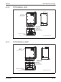
2.4.2
Enclosure design
Inverter placement
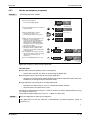
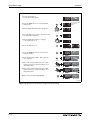
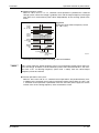
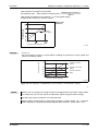
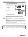
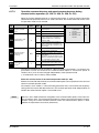
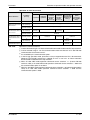
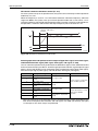
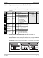
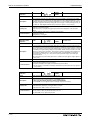
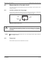
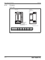
Clearances around the inverter
Always observe the specified minimum clearances to ensure good heat dissipation and adequate accessibility of the frequency inverter for servicing.
Measurement
position
01160 or less
5cm
5cm
5cm
Measurement
position
Temperature [°C] Ambient
LD/SLD
FR-F740 FR-F746 humidity:
90%
150 % −10 to +50 −10 to +40
120 % −10 to +40 −10 to +30
Initial setting
Clearances (front)
01800 or more
≥ 20cm
≥ 10cm
≥ 5cm
≥ 5cm
≥ 10cm
≥ 10cm
1cm or more for 00083 or less
≥ 10cm
≥ 5cm Inverter
Clearances (side)
Inverter
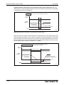
Ambient temperature and humidity
≥ 20cm
1cm or more for 00083 or less
Leave enough clearances and take
cooling measures.
I001005E
Fig. 2-10: Clearances
NOTES
For replacing the cooling fan of the 04320 or more, 30cm of space is necessary in front of
the inverter. Refer to section 8.1.7 for fan replacement.
Since the fan cover of the inverter FR-F746 is fixed with screws, leave enough clearances
so that the screws can be removed with a driver and such.
It is not necessary to leave spaces on both sides of the inverter FR-F746.
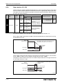
Inverter mounting orientation
Mount the inverter on a wall as specified. Do not mount it horizontally or any other way.
Above the inverter
Heat is blown up from inside the inverter by the small fan built in the unit. Any equipment placed
above the inverter should be heat resistant.
NOTE
FR-F700 EC
The ambient temperature should be 50°C or less for the inverter FR-F740 and 40°C or less
for the inverter FR-F746 at a distance of 5cm from the centre bottom of the inverter.
2 - 11
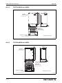
Enclosure design
Installation
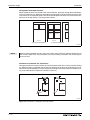
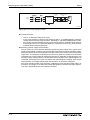
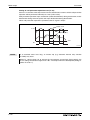
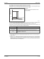
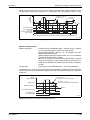
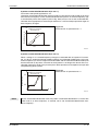
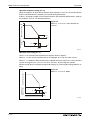
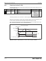
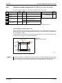
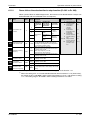
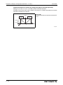
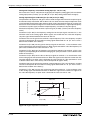
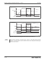
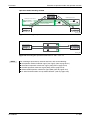
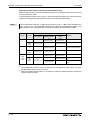
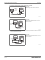
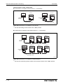
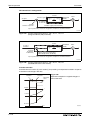
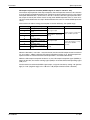
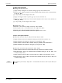
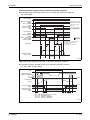
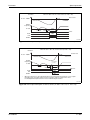
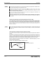
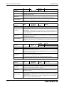
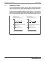
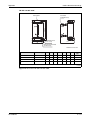
Arrangement of multiple inverters
When multiple inverters are placed in the same enclosure, generally arrange them horizontally
as shown in the figure (a). When it is inevitable to arrange them vertically to minimize space, take
such measures as to provide guides since heat from the bottom inverters can increase the temperatures in the top inverters, causing inverter failures.
Inverter
Inverter
Enclosure
Inverter
Inverter
Guide
Guide
Inverter
Inverter
Guide
Enclosure
a) Horizontal arrangement
b) Vertical arrangement
I001006E
Fig. 2-11: Arrangement of multiple inverters
NOTE
When mounting multiple inverters, fully take caution not to make the ambient temperature of
the inverter higher than the permissible value by providing ventilation and increasing the
enclosure size.
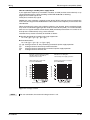
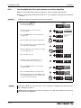
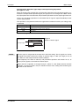
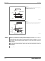
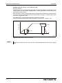
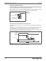
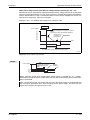
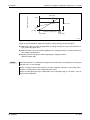
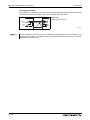
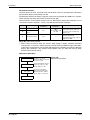
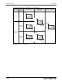
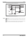
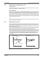
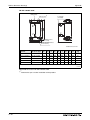
Placement of ventilation fan and inverter
Heat generated in the inverter is blown up from the bottom of the unit as warm air by the cooling
fan. When installing a ventilation fan for that heat, determine the place of ventilation fan installation after fully considering an air flow. (Air passes through areas of low resistance. Make an airway and airflow plates to expose the inverter to cool air.)
Inverter
Good example!
Inverter
Bad example!
I001007E
Fig. 2-12: Placement of ventilation fan and inverter
2 - 12
Installation
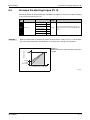
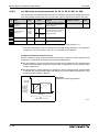
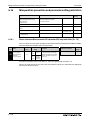
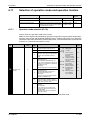
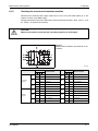
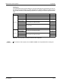
2.4.3
Enclosure design
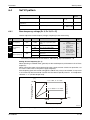
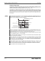
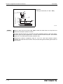
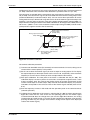
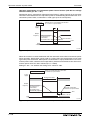
Heatsink protrusion attachment (FR-A7CN)
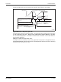
When encasing the inverter in an enclosure, the generated heat amount in an enclosure can be
greatly reduced by installing the heatsink portion of the inverter outside the enclosure. When installing the inverter in a compact enclosure, etc., this installation method is recommended.
For the FR-F740-00023 to 03610, a heatsink can be protruded outside the enclosure using a
heatsink protrusion attachment (FR-A7CN). For a panel cut dimension drawing and an installation procedure of the heatsink protrusion attachment (FR-A7CN) to the inverter, refer to a
manual of "heatsink protrusion attachment".
For the panel cut dimensions of the inverters FR-F740-04320 to 03610 refer to Fig. A-21 in the
appendix.
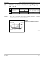
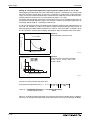
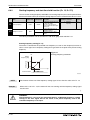
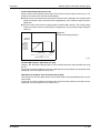
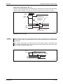
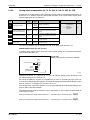
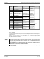
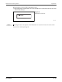
Shift and removal of a rear side installation frame
● FR-F740-05470 to 06830
One installation frame is attached to each of the upper and lower part of the inverter. Change
the position of the rear side installation frame on the upper and lower side of the inverter to
the frontside as shown below. When changing the installation frames, make sure that the
installation orientation is correct.
Shift
Upper installation
frame
Shift
Lower installation
frame
Fig. 2-13:
Shifting the rear side installation frame
(05470 to 06830)
I001381E
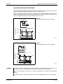
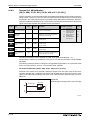
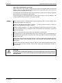
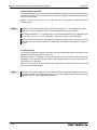
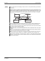
● FR-F740-04320, 04810, 07700 or more
Two installation frames each are attached to the upper and lower part of the inverter. Remove
the rear side installation frame on the upper and lower side of the inverter as shown below.
Removal
Upper installation
frame (rear side)
Fig. 2-14:
Removing the rear side installation frame
(04320, 04810, 07700 or more)
Lower installation
frame (rear side)
Removal
FR-F700 EC
I001382E
2 - 13
Enclosure design
Installation
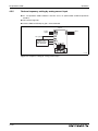
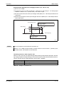
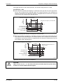
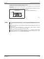
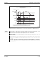
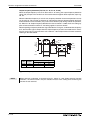
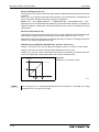
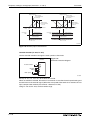
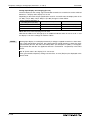
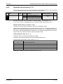
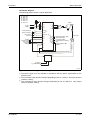
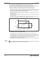
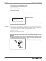
Installation of the inverter
Push the inverter heatsink portion outside the enclosure and fix the enclosure and inverter with
upper and lower installation frame.
Enclosure
Inside the
enclosure
Exhausted air
* For the FR-F740-05470 or more, there are
finger guards behind the enclosure. Therefore,
the thickness of the panel should be less than
10mm and also do not place anything around
finger guards to avoid contact with the finger
guards.
Enclosure
Inverter
Finger guard
Installation
frame
Inverter Type
Cooling
wind
Dimension of the
outside of the
enclosure
D1 [mm]
FR-F740-04320, 04810
185
FR-F740-05470 to 12120
184
I001383E
Fig. 2-15: Installation of the inverter
E
2 - 14
CAUTION:
● Having a cooling fan, the cooling section which comes out of the enclosure can
not be used in the environment of waterdrops, oil, mist, dust, etc.
● Be careful not to drop screws, dust etc. into the inverter and cooling fan section.
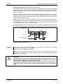
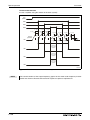
Wiring
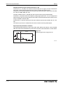
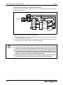
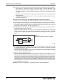
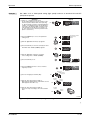
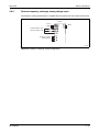
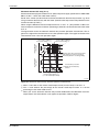
Inverter and peripheral devices
3
Wiring
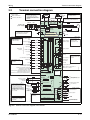
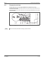
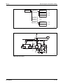
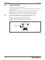
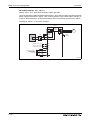
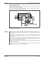
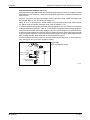
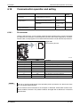
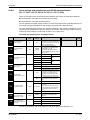
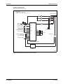
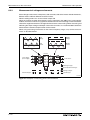
3.1
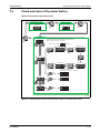
Inverter and peripheral devices
3-phase AC power supply
Use within the permissible power supply
specifications of the inverter.
(Refer to Appendix A.)
PLC
Moulded case circuit breaker (MCCB)
or earth leakage circuit breaker (ELB),
fuse
The breaker ust be selected carefully since
an in-rush current flows in the inverter at
power on. (Refer to section 3.1.1.)
RS-485 terminal block
The inverter can be
connected with
computers such as PLC.
It supports Mitsubishi
inverter protocol and
Modbus-RTU (binary)
protocol.
Magnetic contactor (MC)
Install the magnetic contactor to ensure
safety. Do not use this magnetic contactor
to start and stop the inverter.
Doing so will cause the inverter life to be
shorten.
(Refer to section 3.1.1.)
Inverter (FR-F700 EC)
The life of the inverter is influenced by ambient
temperature. The ambient temperature should
be as low as possible within the permissible
range. Especially when mounting the inverter
inside an enclosure, take cautions of the ambient
temperature. (Refer to section 2.4.2.)
Wrong wiring might lead to damage of the
inverter. The control signal lines must be kept
fully away from the main circuit to protect them
from noise. (Refer to section 3.2.)
Refer to section 3.8.3 for the built-in EMC filter.
Reactor (FR-HAL, FR-HEL)
Reactors (option) should be used when
power harmonics measures are taken, the
power factor is to be improved or the
inverter is installed near a large power
supply system (1000kVA or more).
The inverter may be damaged if you do not
use reactors.
Select the reactor according to the model.
For the 01160 or less, remove the jumpers
across terminals P/+-P1 to connect to the
DC reactor.
(Refer to section 3.1.1.)
DC reactor
(FR-HEL)
For the 01800 or
more, a DC reactor is
supplied. Always
install the reactor.
AC reactor
(FR-HAL)
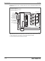
EMC filter
(optional)
Install this as
required.
Earth
Output filter
(optional)
Brake unit
(FR-BU , MT-BU5 )
Earth
High power factor
converter
(FR-HC, MT-HC )
Power supply harmonics can
be greatly suppressed. Install
this as required.
Power regeneration
common converter
(FR-CV )
Power regeneration
converter (MT-RC )
Greater braking capability
is obtained.
Install this as required.
Resistor unit
(FR-BR , MT-BR5 )
The regenerative braking
capability of the inverter can
be exhibited fully. Install this
as required.
Devices connected to the output
Do not install a power factor correction capacitor,
surge suppressor, arrester or radio noise filter on
the output side of the inverter.
When installing a moulded case circuit breaker on
the output side of the inverter, contact each
manufacturer for selection of the moulded case
circuit breaker.
Earth
To prevent an electric shock, always earth the
motor and inverter.
Compatible
with the 01160 or less.
Compatible with the 01800 or more.
I001008E
Fig. 3-1: System configuration overview
FR-F700 EC
3-1
Inverter and peripheral devices
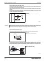
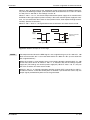
NOTES
Wiring
Do not install a power factor correction capacitor or surge suppressor on the inverter output
side. This will cause the inverter to trip or the capacitor and surge suppressor to be damaged. If any of the above devices are connected, immediately remove them.
Electromagnetic Compatibility
Operation of the frequency inverter can cause electromagnetic interference in the input and
output that can be propagated by cable (via the power input lines), by wireless radiation to
nearby equipment (e.g. AM radios) or via data and signal lines.
Activate the integrated EMC filter (and an additional optional filter if present) to reduce air
propagated interference on the input side of the inverter. Use AC or DC reactors to reduce
line propagated noise (harmonics). Use shielded motor power lines to reduce output noise
(refer also to section 3.8 Electromagnetic Compatibility).
Refer to the instruction manual of each option and peripheral devices for details of peripheral devices.
3-2
Wiring
Inverter and peripheral devices
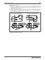
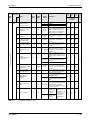
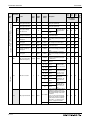
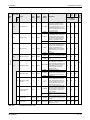
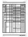
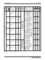
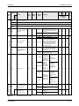
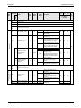
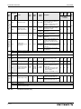
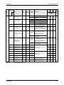
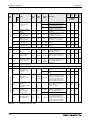
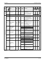
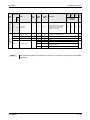
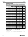
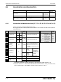
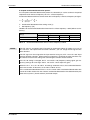
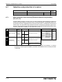
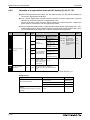
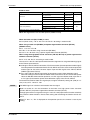
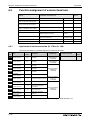
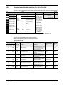
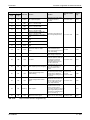
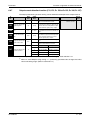
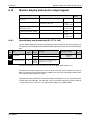
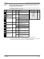
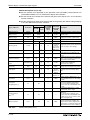
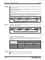
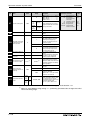
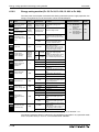
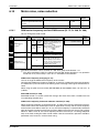
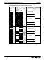
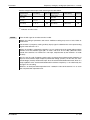
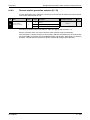
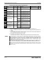
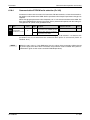
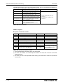
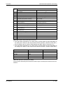
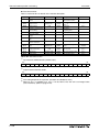
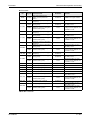
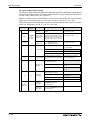
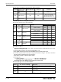
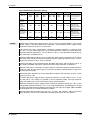
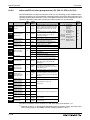
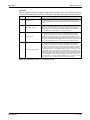
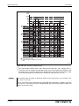
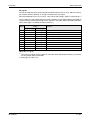
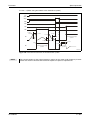
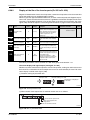
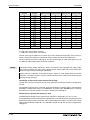
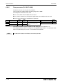
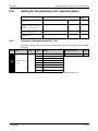
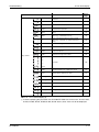
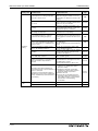
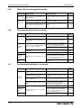
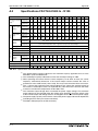
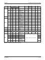
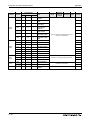
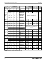
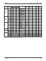
3.1.1
Peripheral devices
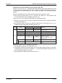
Check the motor capacity of the inverter you purchased. Appropriate peripheral devices must be
selected according to the capacity. Refer to the following list and prepare appropriate peripheral
devices:
Input Side
Magnetic Contactor Breaker Selection Motor
Output
[kW] Applicable Inverter
Type
Reactor connection
Without
With
With commercial
power-supply
operation
Reactor connection
Without
With
0.75
FR-F740/746-00023-EC
NF32 xx 3P 6 A
NF32 xx 3P 4 A
NF32 xx 3P 6 A
S-N10
S-N10
1.5
FR-F740/746-00038-EC
NF32 xx 3P 10 A
NF32 xx 3P 6 A
NF32 xx 3P 10 A
S-N10
S-N10
2.2
FR-F740/746-00052-EC
NF32 xx 3P 10 A
NF32 xx 3P 10 A
NF32 xx 3P 10 A
S-N10
S-N10
3.7
FR-F740/746-00083-EC
NF32 xx 3P 16 A
NF32 xx 3P 10 A
NF32 xx 3P 16 A
S-N10
S-N10
5.5
FR-F740/746-00126-EC
NF32 xx 3P 20 A
NF32 xx 3P 16 A
NF32 xx 3P 20 A
S-N20
S-N11
7.5
FR-F740/746-00170-EC
NF32 xx 3P 32 A
NF32 xx 3P 25 A
NF32 xx 3P 32 A
S-N20
S-N20
11
FR-F740/746-00250-EC
NF63 xx 3P 40 A
NF32 xx 3P 32 A
NF63 xx 3P 40 A
S-N20
S-N20
15
FR-F740/746-00310-EC
NF63 xx 3P 50 A
NF63 xx 3P 40 A
NF63 xx 3P 50 A
S-N25
S-N21
18.5
FR-F740/746-00380-EC
NF63 xx 3P 63 A
NF63 xx 3P 50 A
NF63 xx 3P 63 A
S-N35
S-N25
22
FR-F740/746-00470-EC
NF125 xx 3P 100 A
NF63 xx 3P 63 A
NF125 xx 3P 100 A
S-N35
S-N25
30
FR-F740/746-00620-EC
NF125 xx 3P 100 A
NF125 xx 3P 100 A
NF125 xx 3P 100 A
S-N50
S-N35
37
FR-F740/746-00770-EC
NF125 xx 3P 125 A
NF125 xx 3P 100 A
NF125 xx 3P 125 A
S-N65
S-N50
45
FR-F740/746-00930-EC
NF160 xx 3P 163 A
NF125 xx 3P 125 A
NF160 xx 3P 163 A
S-N80
S-N65
55
FR-F740/746-01160-EC
NF250 xx 3P 250 A
NF160 xx 3P 163 A
NF250 xx 3P 250 A
S-N80
S-N80
FR-F740-01800-EC
—
NF250 xx 3P 250 A
NF250 xx 3P 400 A
—
S-N95
FR-F740-01800-EC
—
NF250 xx 3P 250 A
NF250 xx 3P 400 A
—
S-N150
75
90
FR-F740-02160-EC
—
NF250 xx 3P 250 A
NF400 xx 3P 400 A
—
S-N180
132
FR-F740-02600-EC
—
NF400 xx 3P 400 A
NF400 xx 3P 400 A
—
S-N220
160
FR-F740-03250-EC —
NF400 xx 3P 400 A
NF630 xx 3P 500 A
—
S-N300
185
FR-F740-03610-EC
—
NF400 xx 3P 400 A
NF630 xx 3P 500 A
—
S-N300
FR-F740-04320-EC
—
NF630 xx 3P 500 A
NF630 xx 3P 600 A
—
S-N400
110
220
FR-F740-04810-EC
—
NF630 xx 3P 600 A
NF630 xx 3P 600 A
—
S-N600
280
FR-F740-05470-EC
—
NF630 xx 3P 600 A
NF800 xx 3P 800 A
—
S-N600
315
FR-F740-06100-EC —
NF800 xx 3P 700 A
NF800 xx 3P 800 A
—
S-N600
250
—
NF800 xx 3P 800 A
NF800 xx 3P 800 A
—
S-N600
400
FR-F740-07700-EC
—
NF1000 xx 3P 900 A
NF1000 xx 3P 1000 A
—
S-N800
450
FR-F740-08660-EC —
NF1000 xx 3P 1000 A
NF1000 xx 3P 1000 A
—
1000 A
Rated
current
500
FR-F740-09620-EC —
NF1250 xx 3P 1200 A
NF1250 xx 3P 1200 A
—
1000 A
Rated
current
560
FR-F740-10940-EC —
NF1600 xx 3P 1500 A
NF1600 xx 3P 1600 A
—
1200 A
Rated
current
630
FR-F740-12120-EC —
AE2000-SS 3P 2000 A
AE2000-SS 3P 2000 A
—
1400 A
Rated
current
355
FR-F740-6830-EC
Tab. 3-1:
FR-F700 EC
Breakers and contactors
3-3
Inverter and peripheral devices
Wiring
Selections for use of the Mitsubishi 4-pole standard motor with power supply voltage of
400V AC 50Hz.
Select the MCCB according to the inverter power supply capacity. Install one MCCB per
inverter.
MCCB
F700
M
3~
MCCB
F700
M
3~
Fig. 3-2:
Installation of the breakers
I001332E
Magnetic contactor is selected based on the AC-1 class. The electrical durability of magnetic
contactor is 500,000 times. When the magnetic contactor is used for emergency stop during
motor driving, the electrical durability is 25 times.
When using the MC for emergancy stop during motor driving or using on the motor side
during commercial-power supply operation, select the MC with class AC-3 rated current for
the motor rated current.
When the breaker on the inverter primary side trips, check for the wiring fault (short circuit),
damage to internal parts of the inverter, etc. Identify the cause of the trip, then remove the
cause and power on the breaker.
The supplied DC reactor has to be installed.
3-4
Wiring
Terminal connection diagram
3.2
Terminal connection diagram
Remove the jumper for the 01160
or less if a DC reactor is
connected. The DC reactor
supplied with the 01800 or more
should be connected to these
terminals.
Main circuit terminal
Control circuit terminal
MCCB
*2 To supply power to the control circuit
separately, remove the jumper
across R1/L11 and S1/L21.
Earth
P1
P/+ PR*7
PX*7
Inrush current
limit circuit
ON
R1/L11
S1/L21
*2
*7 Do not use PR and PX terminals.
Please do not remove the jumper
connected to terminal PR and PX.
Jumper
Jumper
R/L1
S/L2
T/L3
3-phase AC
power supply
OFF
N/- CN8*6
U
V
W
Motor
M
3~
EMC filter
ON/OFF
connector
Main circuit
Earth
Earth
Control circuit
Control input signals (No voltage input allowed)
B2
RM
Middle speed
Jog mode
Second function selection
Output stop
JOG
RUN
RT
SU
MRS
IPF
RES *3
AU
Terminal 4 input selection
(Current input selection)
CS PTC
Selection of automatic restart after
instantaneous power failure
SD
Contact input common (sink*)
24V DC power supply/max. 100mA load current
Contact input common (source*)
*5
*4 Terminal input specifications
can be changed by analog
input specifications switchover
(Pr. 73, Pr. 267). Set the
voltage/current input switch in
the OFF position to select
voltage input (0 to 5V/0 to 10V)
and ON to select current input
(0 to 20mA).
SE
Up to frequency
Terminal functions vary
with the output terminal
assignment set in Pr. 190
to Pr. 194.
Instantaneous
power failure
Overload
Frequency detection
Open collector output common
Sink/source common
24V
PU
connector
10E(+10V)
10(+5V)
2
2
5
1
ON
OFF
0 to 5V DC
0 to 10V DC
4 to 20mA DC
4 2
CA
(-)
AM
Analog common
Auxiliary
input
(+)
(-)
1
0 to ±10V DC
0 to ±5V DC
Terminal 4
input
(Current
input)
(+)
(-)
4
4 to 20mA DC
0 to 5V DC
0 to 10V DC
(+)
Analog current output
(0 to 20mA DC)
*4
5
*4
(+)
Analog signal output
(0 to 10V DC)
(-)
TXD+
TXD-
*4
RS-485 terminals
Data transmission
RXD+
RXD-
Connector
for plug-in option
connection
*5 It is recommended to use 2W,
1kΩ when the frequency
setting signal is changed
frequently.
Running
*4 Voltage/current
input switch
Frequency setting signal (analog)
Frequency setting
potentiometer
½W, 1kΩ
FU
PC
*(Common for external power supply transistor)
3
OL
AU
SINK
Reset
Relay output 2
A2
RL
Low speed
Relay output 1
(Alarm output)
Terminal functions vary
with the output terminal
assignment set in
Pr. 195 and Pr. 196.
C2
RH
High speed
*3 AU terminal can be
used as PTC input
terminal.
A1
STOP
Start self-holding
selection
Multi-speed
selection
B1
STR
Reverse rotation
start
Relay output
C1
STF
Forward rotation
start
SOURCE
Terminal functions vary
with the input terminal
assignment set in
Pr. 178 to Pr. 189.
*6 A CN8 (for MT-BU5)
connector is provided with
the 01800 or more.
Brake unit
(Option)
MC
Jumper
Resistor unit
(Option)
*1
*1 DC reactor (FR-HEL)
Source Logic
SG
Data reception
GND
Option connector
Terminating
resistor
VCC
load
5V (Permissible
current 100 mA)
I002090E
Fig. 3-3: Terminal connection diagram of the inverter
FR-F700 EC
3-5
Terminal connection diagram
NOTES
Wiring
To prevent a malfunction due to noise, keep the signal cables more than 10cm away from
the power cables.
After wiring, wire offcuts must not be left in the inverter.
Wire offcuts can cause an alarm, failure or malfunction. Always keep the inverter clean.
When drilling mounting holes in an enclosure etc., take care not to allow chips and other foreign matter to enter the inverter.
Set the voltage/current input switch correctly. Operation with a wrong setting may cause a
fault, failure or malfunction.
3-6
Wiring
Main circuit connection
3.3
Main circuit connection
3.3.1
Specification of main circuit terminal
Terminal
Name
Description
L1, L2, L3
AC power input
Connect to the commercial power supply
(380–500V AC, 50/60Hz)
Keep these terminals open when using the high power factor converter
(FR-HC, MT-HC) or power regeneration common converter (FR-CV).
U, V, W
Inverter output
Voltage ouput of the inverter
(3 ~, 0V–power supply voltage, 0,5–400 Hz)
L11, L21
Power supply for
control circuit
Connected to the AC power supply terminals L1 and L2. To retain the alarm
display and alarm output or when using the high power factor converter
(FR-C, MT-HC) or power regeneration common converter (FR-CV), remove
the jumpers from terminals L1-L11 and L2-L21 and apply external power to
these terminals.
Do not turn off the power supply for control circuit (L11, L21) with the main
circuit power (L1, L2, L3) on. Doing so may damage the inverter. The circuit
should be configured so that the main circuit power (L1, L2, L3) is also
turned off when the power supply for control circuit (L11, L21) is off.
00380 or less: 60VA, 00470 or more: 80VA
P/+, N/−
Brake unit connection Connect the brake unit (FR-BU, BU and MT-BU5), power regeneration common converter (FR-CV), high power factor converter (FR-HC and MT-HC) or
power regeneration converter (MT-RC).
P/+, P1
DC reactor
connection
PR, PX
Please do not remove or use terminals PR and PX or the jumper connected.
For the 01160 or less, remove the jumper across terminals P/+-P1 and connect the optional DC reactor. (For the 01800 or more, a DC reactor is supplied as standard.)
PE
For earthing the inverter chassis. Must be earthed.
Tab. 3-2: Specification of main circuit terminal
3.3.2
Terminal layout and wiring
FR-F740/746-00023 to 00126-EC
FR-F740/746-00170 and 00250-EC
Jumper
Screw size M4
CHARGE lamp
Jumper
Jumper
Jumper
Screw size M4
L1 L2 L3
Power supply
M
3~
CHARGE lamp
Screw size M4
Motor
Power supply
L1 L2 L3
Screw size M4
I001010E
M
3~
Motor
I001011E
Tab. 3-3: Terminal layout and wiring (1)
FR-F700 EC
3-7
Main circuit connection
Wiring
FR-F740/746-00310 and 00380-EC
FR-F740/746-00470 and 00620-EC
Screw size M4
Screw size M4
CHARGE lamp
Jumper
CHARGE lamp
Jumper
Screw size M6
Jumper
Screw size M5
L1
L2
M
3~
L3
Power supply
L1
L2
L3
Jumper
Motor
M
3~
Power supply
Screw size M6
Motor
Screw size M5
I001012E
FR-F740/746-00770 to 01160-EC
I001013E
FR-F740-01800 and 02600-EC
Screw size M4
CHARGE lamp
Screw size M4
Jumper
CHARGE lamp
Jumper
Screw size
00770: M6
00930, 01160: M8
Screw size
01800: M8, 02160: M10 Screw size M10
Jumper
L1
L2
L3
Power supply
Screw size
00770: M6
00930, 01160: M8
L1 L2
M
3~
DC reactor
Motor
Screw size
01800: M8
02160, 02600: M10
Motor
I001014E
Tab. 3-3: Terminal layout and wiring (2)
3-8
M
3~
L3
Power supply
Screw size
01800: M8,
02160, 02600: M10
I001015E
Wiring
Main circuit connection
FR-F740-03250 and 03610-EC
FR-F740-04320 and 04810-EC
Screw size M4
Screw size M4
CHARGE lamp
CHARGE lamp
Jumper
Jumper
Screw size M10
Screw size M12
Screw size
M10
L1
L2
Screw size
M10
L3
L1
M
3~
Power supply
L2
L3
M
3~
Power supply
Motor
Motor
DC reactor
DC reactor
Screw size M12
(for option)
Screw size M12
(for option)
I001343E
I001344E
FR-F740-05470 to 12120-EC
Screw size M4
CHARGE lamp
Jumper
—
Screw size M12
L1
L2
L3
M
3~
Power supply
Motor
DC reactor
Screw size M10
I001345E
Tab. 3-3: Terminal layout and wiring (3)
E
CAUTION:
● The power supply cables must be connected to R/L1, S/L2, T/L3. Never connect the
power cable to the U, V, W of the inverter. Doing so will damage the inverter. (Phase
sequence needs not to be matched.)
● Connect the motor to U, V, W. At this time, turning on the forward rotation switch
(signal) rotates the motor in the counter clockwise direction when viewed from the
motor shaft.
FR-F700 EC
3-9
Main circuit connection
Wiring
Connection to the conductors
When wiring the inverter main circuit conductor of the 05470 or more, tighten a nut from the right
side of the conductor. When wiring two wires, place wires on both sides of the conductor. (Refer
to the drawing below.) For wiring, use bolts (nuts) provided with the inverter.
Fig. 3-4:
Connection to the conductors
I001346E
Wiring cover
The frequency inverters FR-F740-00470 and 00620 are equipped with a combed shaped wiring
cover. For the hook of the wiring cover, cut off the necessary parts using a pair of long-nose
pliers etc.
I000999E
Fig. 3-5: Combed shaped wiring cover
NOTE
Cut off the same numbers of lugs as wires. If you cut off unnecessary parts and no wires are
connected, the protective structure (JEM 1030) of the inverter becomes open type (IP00).
Cable bushing FR-F746
Remove the rubber bushing and use the cable gland (equivalent for SKINTOPST-M series,
locknuts GMP-GL-M series and Gaskets GMP series, LAPP) so that cable wiring satisfies IP54.
For a hole in which the cable is not led, the rubber bush may be used without replacing.
3 - 10
Wiring
Main circuit connection
Cables and wiring length
Select the recommended cable size to ensure that a voltage drop will be 2% max.
If the wiring distance is long between the inverter and motor, a main circuit cable voltage drop
will cause the motor torque to decrease especially at the output of a low frequency.
The following table indicates a selection example for the wiring length of 20m.
400V class
(when input power supply is 440V based on a rated current for 110% overload for 1 minute)
Cable Size
Crimping
Terminal
Terminal Tightening
HIV, etc. [mm²] AWG PVC, etc. [mm²] Applicable Inverter Type Screw
Torque
Earth
Earth
Size [Nm]
L1, L2, U, V, W L1, L2, U, V, W cable L1, L2, U, V, W L1, L2, U, V, W cable
L3, P1, P
L3, P1, P
L3, P1, P
L3, P1, P
gauge
gauge
FR-F740/746-00023 to
00083-EC
M4
1.5
FR-F740/746-00126-EC
M4
1.5
2-4
2-4
FR-F740/746-00170-EC
M4
1.5
5.5-4
5.5-4
FR-F740/746-00250-EC
M4
1.5
5.5-4
5.5-4
FR-F740/746-00310-EC
M5
2.5
8-5
FR-F740/746-00380-EC
M5
2.5
14-5
FR-F740/746-00470-EC
M6
4.4
FR-F740/746-00620-EC
M6
4.4
FR-F740/746-00770-EC
M6
FR-F740/746-00930-EC
FR-F740/746-01160-EC
2-4
2-4
2
2
2
14
14
2.5
2.5
2.5
2
2
3.5
12
14
2.5
2.5
4
3.5
3.5
3.5
12
12
4
4
4
5.5
5.5
8
10
10
6
6
10
8-5
8
8
8
8
8
10
10
10
8-5
14
8
14
6
8
16
10
16
22-6
14-6
22
14
14
4
6
25
16
16
22-6
22-6
22
22
14
4
4
25
25
16
4.4
22-6
22-6
22
22
14
4
4
25
25
16
M8
7.8
38-8
38-8
38
38
22
1
2
50
50
25
M8
7.8
60-8
60-8
60
60
22
1/0
1/0
50
50
25
FR-F740-01800-EC
M8
7.8
60-10
60-10
60
60
38
1/0
1/0
50
50
25
FR-F740-02160-EC
M10
14.7
100-10 100-10
100
100
38
3/0
3/0
70
70
35
FR-F740-02600-EC
M10
14.7
100-10 150-10
100
125
38
4/0
4/0
95
95
50
FR-F740-03250-EC
M10
14.7
150-10 150-10
125
125
38
250
250
120
120
70
150
150
300
300
150
FR-F740-03610-EC
M10
14.7
150-10 150-10
FR-F740-04320-EC
M12/M10
24.5
100-12 100-12 2 × 100 2 × 100
38
150
95
2 × 4/0 2 × 4/0 2 × 95
2 × 95
95
FR-F740-04810-EC
M12/M10
24.5
100-12 100-12 2 × 100 2 × 100
FR-F740-05470-EC
M12/M10
24.5
150-12 150-12 2 × 125 2 × 125
38
2 × 4/0 2 × 4/0 2 × 95
2 × 95
95
38
2 × 250 2 × 250 2 × 120 2 × 120
120
FR-F740-06100-EC
M12/M10
24.5
FR-F740-06830-EC
M12/M10
24.5
150-12 150-12 2 × 150 2 × 150
38
2 × 300 2 × 300 2 × 150 2 × 150
150
200-12 200-12 2 × 200 2 × 200
60
2 × 350 2 × 350 2 × 185 2 × 185 2 × 95
FR-F740-07700-EC
M12/M10
FR-F740-08660-EC
M12/M10
24.5
C2-200 C2-200 2 × 200 2 × 200
60
2 × 400 2 × 400 2 × 185 2 × 185 2 × 95
24.5
C2-250 C2-250 2 × 250 2 × 250
60
FR-F740-09620-EC
2 × 500 2 × 500 2 × 240 2 × 240 2 × 120
M12/M10
24.5
C2-250 C2-250 2 × 250 2 × 250
100
2 × 500 2 × 500 2 × 240 2 × 240 2 × 120
FR-F740-10940-EC
M12/M10
24.5
C2-200 C2-200 3 × 200 3 × 200
100
3 × 350 3 × 350 3 × 185 3 × 185 2 × 150
FR-F740-12120-EC
M12/M10
24.5
C2-200 C2-200 3 × 200 3 × 200
100
3 × 400 3 × 400 3 × 185 3 × 185 2 × 150
Tab. 3-4:
FR-F700 EC
38
Cable size
3 - 11
Main circuit connection
Wiring
For the 01160 or less, the recommended cable size is that of the HIV cable (600V class 2
vinyl-insulated cable) with continuous maximum permissible temperature of 75°C. Assumes
that the ambient temperature is 50°C or less and the wiring distance is 20m or less.
For the 01800 or more, the recommended cable size is that of LMFC (heat resistant flexible
cross-linked polyethylene insulated cable) with continuous maximum permissible temperature of 95°C. Assumes that the ambient temperature is 50°C or less and wiring is performed
in an enclosure.
For the 00930 or less, the recommended cable size is that of the THHW cable with
continuous maximum permissible temperature of 75°C. Assumes that the ambient temperature is 40°C or less and the wiring distance is 20m or less.
For the 01160 or more, the recommended cable size is that of THHN cable with continuous
maximum permissible temperature of 90°C. Assumes that the ambient temperature is 40°C
or less and wiring is performed in an enclosure.
For the 00930 or less, the recommended cable size is that of the PVC cable with continuous
maximum permissible temperature of 70°C. Assumes that the ambient temperature is 40°C
or less and the wiring distance is 20m or less.
For the 01160 or more, the recommended cable size is that of XLPE cable with continuous
maximum permissible temperature of 90°C. Assumes that the ambient temperature is 40°C
or less and wiring is performed in an enclosure.
The terminal screw size indicates the terminal size for R/L1, S/L2, T/L3, U, V, W, P/+, N/–,
P1 and a screw for earthing.
The line voltage drop can be calculated by the following expression:
3 × wire resistance [Ω ] × wiring distance [m] × current [A]Line voltage drop [V] = ---------------------------------------------------------------------------------------------------------------------------------------------------------1000
Use a larger diameter cable when the wiring distance is long or when it is desired to decrease
the voltage drop (torque reduction) in the low speed range.
E
CAUTION:
● Tighten the terminal screw to the specified torque. A screw that has been tightened
too loosely can cause a short circuit or malfunction. A screw that has been
tightened too tightly can cause a short circuit or malfunction due to the unit
breakage.
● Use crimping terminals with insulation sleeve to wire the power supply and motor.
3 - 12
Wiring
Main circuit connection
Notes on earthing
Leakage currents flow in the inverter or the EMC filter respectively. To prevent an electric shock,
the inverter, input filter and motor must be earthed. (This inverter must be earthed. Earthing
must conform to the requirements of national and local safety regulations and electrical codes.
(JIS, NEC section 250, IEC 536 class 1 and other applicable standards)).
Use the dedicated earth terminal to earth the inverter. (Do not use the screw in the casing, chassis, etc.)
Use the thickest possible earth cable. Use the cable whose size is equal to or greater than that
indicated in Tab. 3-4, and minimize the cable length. The earthing point should be as near as
possible to the inverter.
Always earth the motor and inverter
● Purpose of earthing
Generally, an electrical apparatus has an earth terminal, which must be connected to the
ground before use.
An electrical circuit is usually insulated by an insulating material and encased. However, it
is impossible to manufacture an insulating material that can shut off a leakage current
completely, and actually, a slight current flow into the case. The purpose of earthing the case
of an electrical apparatus is to prevent operator from getting an electric shock from this
leakage current when touching it.
To avoid the influence of external noises, this earthing is important to audio equipment,
sensors, computers and other apparatuses that handle low-level signals or operate very fast.
● Earthing methods and earthing work
As described previously, earthing is roughly classified into an electrical shock prevention
type and a noise affected malfunction prevention type. Therefore, these two types should
be discriminated clearly, and the following work must be done to prevent the leakage current
having the inverter's high frequency components from entering the malfunction prevention
type earthing:
– Where possible, use independent earthing for the inverter. If independent earthing (I) is
impossible, use joint earthing (II) where the inverter is connected with the other equipment at an earthing point. Joint earthing as in (III) must be avoided as the inverter is
connected with the other equipment by a common earth cable.
Also a leakage current including many high frequency components flows in the earth
cables of the inverter and inverter-driven motor. Therefore, they must use the independent earthing method and be separated from the earthing of equipment sensitive to the
aforementioned noises.
In a tall building, it will be a good policy to use the noise malfunction prevention type
earthing with steel frames and carry out electric shock prevention type earthing in the
independent earthing method.
– This inverter must be earthed. Earthing must conform to the requirements of national
and local safety regulations and electrical codes. (JIS, NEC section 250, IEC 536 class
1 and other applicable standards).
– Use the thickest possible earth cable. The earth cable should be of not less than the size
indicated in Tab. 3-4.
– The grounding point should be as near as possible to the inverter, and the ground wire
length should be as short as possible.
– Run the earth cable as far away as possible from the I/O wiring of equipment sensitive
to noises and run them in parallel in the minimum distance.
Inverter
Other
equipment
(I) Independent earthing
(best solution)
Inverter
Other
equipment
(II) Common earthing
(good solution)
Inverter
Other
equipment
(III) Common earthing
(not allowed)
I001016E
Fig. 3-6: Earthing the drive
FR-F700 EC
3 - 13
Main circuit connection
Wiring
Total wiring length
The maximum possible length of the motor cables depends on the capacity of the inverter and
the selected carrier frequency. The cables should never be longer than 500m (unshielded).
The lengths in the following table are for unshielded cables. When shielded cables are use divide the values listed in the table by 2. Note that the values are for the total wiring length – if you
connect more than one motor in parallel you must add the lengths of the individual motor cables.
Pr. 72 "PWM frequency selection" setting (carrier frequency)
00023
00038
≥ 00052
≤ 2 (2kHz)
300m
500m
500m
3 (3kHz), 4 (4kHz)
200m
300m
500m
5 (5kHz) to 9 (9kHz)
100m
≥ 10 (10kHz)
50m
Tab. 3-5: Total wiring length
NOTE
For the 01800 or more, the setting range of Pr. 72 PWM frequency selection is "0 to 6".
Fig. 3-7:
Total wiring length (00038 or more)
≤ 500m
300m
300m
300m + 300m = 600m
I001017E
Note that the motor windings are subjected to significantly higher loads when the motor is operated by inverter than with normal mains operation. The motors must be approved for inverter
operation by the manufacturer (refer also to section 3.8.5).
3 - 14
Wiring
3.4
Control circuit specifications
Control circuit specifications
The functions of the terminals highlighted in grey can be adjusted with parameters 178 to 196
"Input/Output terminal function assignment" (refer to section 6.9). The listed settings show the
default configuration as shipped, which you can restore by resetting to the factory defaults.
Input signals
Terminal
Description
STF
Forward rotation
start
Turn on the STF signal to
start forward rotation and
turn it off to stop.
STR
Reverse rotation
start
Turn on the STR signal to
start reverse rotation and
turn it off to stop.
STOP
Start self holding
selection
Turn on the STOP signal to self-hold the start
signal.
6-96
Multi-speed
selection
Multi-speed can be selected according to the
combination of RH, RM and RL signals.
6-96
Jog mode
selection
Turn on the JOG signal to select Jog operation
(initial setting) and turn on the start signal to
start Jog operation.
6-96
Second
function
Turn on the RT signal to select second
function.
When the second function such as "second
torque boost" and "second V/F (base frequency)" are set, turning on the RT signal
selects these functions.
6-96
MRS
Output stop
Turn on the MRS signal (20ms or more) to stop
the inverter output.
Use to shut off the inverter output when stopping the motor by electromagnetic brake.
RES
Reset
RH, RM, RL
JOG
RT
Contact input
Rated
Refer to
Specifications
Name
SD
6-96
6-96
Input resistance: 4,7kΩ
Voltage at
opening:
21 to 27V DC
Used to reset alarm output provided when pro- Contacts at
tective function is activated.
short-circuited:
Turn on the RES signal for more than 0.1s,
4 to 6mA DC
then turn it off.
Initial setting is for reset always. By setting
Pr. 75, reset can be set to enabled only at an
inverter alarm occurrence. Recover about 1s
after reset is cancelled.
6-96
6-96
Terminal 4
input selection
Terminal 4 is made valid only when the AU signal is turned on. (The frequency setting signal
can be set between 4 and 20mA DC.)
Turning the AU signal on makes terminal 2
(voltage input) invalid.
6-170
PTC input
AU terminal is used as PTC input terminal
(thermal protection of the motor). When using
it as PTC input terminal, set the AU/PTC
switch to PTC and assign the PTC function to
the AU input terminal.
6-80
Selection of
automatic
restart after
instantaneous
power failure
When the CS signal is left on, the inverter
restarts automatically at power restoration.
Note that restart setting is necessary for this
operation. In the initial setting, a restart is
disabled. (Refer to Pr. 57 in section 6.11.)
6-96
External transistor
common, contact
input common
(sink)
A determined control function is activated, if
the corresponding terminal is connected to the
terminal SD (sink logic). The SD terminal is
isolated from the digital circuits via opto couplers.
The terminal is isolated from the reference
potential of the analog circuit (terminal 5).
Common reference potential (0V) for 24V DC/
0.1A output (PC terminal).
AU
CS
When the STF
and STR signals
are turned on
simultaneously,
the stop command is given.
—
—
Tab. 3-6: Input signals (1)
FR-F700 EC
3 - 15
Control circuit specifications
Contact input
Terminal
PC
10E
(Output voltage 10V DC)
Frequency setting
10
(Output voltage 5V DC)
Wiring
Name
Description
Rated
Refer to
Specifications
24V DC
power supply,
contact input
common
(source)
24V DC/0.1A output
With negative logic and control via open collector transistors (e.g. a PLC) the positive pole
of an external power source must be connected to the PC terminal. With positive logic
the PC terminal is used as a common reference for the control inputs. This means that
when positive logic is selected (default setting
of the EC units) the corresponding control
function is activated by connecting its terminal
to the PC terminal.
Power supply
voltage range:
19.2 to
28.8V DC
Current consumption:
100mA
3-26
10V DC ± 0,4V,
Permissible
load current
10mA
6-170
Frequency setting
power supply
When connecting the frequency setting potentiometer at an initial status, connect it to terminal 10.
Change the input specifications with Pr. 73
when connecting it to terminal 10E.
(Refer to section 6.15.2.)
Recommended potentiometer:
1 kΩ, 2 W linear, multi turn potentiometer
5,2V DC ± 0,2V,
Permissible
load current
10mA
6-170
2
Frequency setting
(voltage)
4
Frequency setting
(current)
Inputting 0 to 5V DC (or 0 to 10V, 0/4 to 20mA)
provides the maximum output frequency at 5V
(10V, 20mA) and makes input and output proportional. Use Pr.73 to switch from among input
0 to 5V DC (initial setting), 0 to 10V DC, and 0/4
to 20mA.
Set the voltage/current input switch in the ON
position to select current input (0/4 to 20mA). Voltage input:
Input resistance:
10kΩ ± 1kΩ
Maximum
permissible
voltage:
20V DC
Current input:
Input resistance:
245Ω ± 5Ω
(while power is on)
Inputting 0/4 to 20mA DC (or 0 to 5V, 0 to 10V) Maximum
permissible
provides the maximum output frequency at
current: 30mA
20mA (5V, 10V) makes input and output pro(while power is off)
portional. This input signal is valid only when
Voltage/current
the AU signal is on (terminal 2 input is invalid).
input switch
Use Pr. 267 to switch between the input 0/4 to
2
4
20mA (initial value) and 0 to 5V DC, 0 to 10V DC.
Set the voltage/current input switch in the OFF
position to select voltage input (0 to 5V/0 to
10V). 6-170
6-170
Switch 1
Switch 2
1
5
Frequency setting
auxiliary
0–±5 (10)V DC
Frequency setting
common and
analog outputs
Inputting 0 to ±5V DC or 0 to ±10V DC adds
this signal to terminal 2 or 4 frequency setting
signal. Use Pr. 73 to switch between the input 0
to ±5V DC and 0 to ±10V DC (initial setting).
Input resistance:
10kΩ ± 1kΩ
Maximum
permissible
voltage:
±20V DC
Terminal 5 provides the common reference
potential (0V) for all analog set point values
and for the analog output signals CA (current)
and AM (voltage). The terminal is isolated from
the digital circuit’s reference potential (SD).
This terminal should not be grounded. If local —
regulations require grounding of the reference
potential note that this can propagate any
noise in the ground potential to the control
electronics, thus increasing sensitivity to interference.
6-170
6-170
Tab. 3-6: Input signals (2)
3 - 16
Set Pr. 73, Pr. 267, and a voltage/current input switch correctly, then input an analog signal
in accordance with the setting.
Applying a voltage signal with voltage/current input switch on (current input is selected) or
a current signal with switch off (voltage input is selected) could cause component damage
of the inverter or analog circuit of signal output devices. (For details, refer to section 6.15.1.)
Wiring
Control circuit specifications
Output signals
Relay
Terminal
Rated
Refer to
Specifications
Name
Description
A1, B1, C1
Relay output 1
(alarm output)
The alarm is output via relay contacts. The
block diagram shows the normal operation and
voltage free status. If the protective function is
activated, the relay picks up.
B1
A1
A2, B2, C2
Relay output 2
C1
RUN
6-107
6-107
Inverter running
Switched low when the inverter output frequency is equal to or higher than the starting
frequency (initial value 0.5Hz).
Switched high during stop or DC injection
brake operation.
6-107
Up to frequency
The SU output supports a
monitoring of frequency setting value and frequency
current value. The output is
switched low, once the frequency current value (output frequency of the
inverter) approaches the
frequency setting value
(determined by the setting
value signal) within a preset
range of tolerance (Pr. 41).
Switched high during acceleration/deceleration and at
a stop.
6-107
Open collector
SU
Contact
capacity:
230V/0,3A AC
(Power
factor: 0,4)
or
30V/0,3A DC.
Permissible
load:
24V DC, 0,1A
(A voltage drop
is 3.4V maximum when the
signal is on.)
OL
Overload alarm
The OL is switched low, if
the output current of the
inverter exceeds the current limit preset in Pr. 22
and the stall prevention is
activated. If the output current of the inverter falls
below the current limit preset in Pr. 22, the signal at
the OL output is switched
high.
IPF
Instantaneous
power failure
The output is switched low
for a temporary power failure within a range of
15ms ≤ tIPF ≤ 100ms or for
under voltage.
6-107
FU
Frequency
detection
The output is switched low
once the output frequency
exceeds a value preset in
Pr. 42 (or 43). Otherwise the
FU output is switched high.
6-107
SE
Open collector
output common
Reference potential for the signals RUN, SU,
OL, IPF, and FU. This terminal is isolated from —
the reference potential of the control circuit SD.
Alarm code
(4 bit) (Refer to
section 6.12.2)
6-107
—
Tab. 3-7: Output signals (1)
FR-F700 EC
3 - 17
Control circuit specifications
Terminal
Analog output
CA
AM
Wiring
Name
Description
Analog current
output
Analog voltage
output
Select one e.g. output frequency from monitor items.
The output signal is proportional to the magnitude of
the corresponding monitoring item.
Not output during inverter
reset.
Rated
Refer to
Specifications
Load
impedance:
200Ω–450Ω
Output signal:
0–20mA
6-130
Output signal:
Output item:
0–10V DC
Output frequency Permissible
(initial setting)
load current:
1 mA
(load impedance:
≥ 10kΩ)
Resolution:
8 bit
6-130
Tab. 3-7: Output signals (2)
Communication
Terminal
RS-485 terminal
RS-485
—
TXD+
TXD−
RXD+
Name
Description
PU connector
With the PU connector, communication can be made
through RS-485. (for connection on a 1:1 basis only)
Conforming standard: EIA-485 (RS-485)
Transmission format: Multidrop
Communication speed: 4800 to 38400bps
Overall length: 500m
6-225
With the RS-485 terminal, communication can be
made through RS-485.
Conforming standard: EIA-485 (RS-485)
Transmission format: Multidrop link
Communication speed: 300 to 38400bps
Overall length: 500m
6-228
Inverter transmission
terminal
RXD−
Inverter reception
terminal
SG
Earth
Tab. 3-8: Communication signals
3 - 18
Refer to
Wiring
3.4.1
Control circuit specifications
Control circuit terminals
I001018E
Fig. 3-8: Terminal layout
Wiring method
Remove about 6mm of the cable insulation. Wire the stripped cable after twisting it to prevent
it from becoming loose. In addition, do not solder it.
Fig. 3-9:
Preparation of the cable
6mm
I001326E
Loosen the terminal screw and insert the cable into the terminal.
Item
Screw size
Tightening torque
Cable size
Screwdriver
Description
M3
0.5Nm–0.6Nm
0.3mm²–0.75mm²
Flat blade screw driver
Edge thickness: 0.4mm × 2.5mm
Tab. 3-9: Connection to the terminals
E
FR-F700 EC
CAUTION:
Undertightening can cause cable disconnection or malfunction. Overtightening can
cause a short circuit or malfunction due to damage to the screw or unit.
3 - 19
Control circuit specifications
Wiring
Common terminals of the control circuits PC, 5, SE
Terminals PC, 5, and SE are all common terminals (0V) for I/O signals and are isolated from
each other. Avoid connecting the terminal PC and 5 and the terminal SE and 5.
Terminal PC is a common terminal for the contact input terminals (STF, STR, STOP, RH, RM,
RL, JOG, RT, MRS, RES, AU, CS).
The open collector circuit is isolated from the internal control circuit by photocoupler.
Terminal 5 is a common terminal for frequency setting signal (terminal 2, 1 or 4), analog current
output terminal (CA) and analog output terminal AM. It should be protected from external noise
using a shielded or twisted cable.
Terminal SE is a common terminal for the open collector output terminal (RUN, SU, OL, IPF,
FU).
The contact input circuit is isolated from the internal control circuit by photocoupler.
Signal inputs by contactless switches
The contacted input terminals of the inverter (STF, STR, STOP, RH, RM, RL, JOG, RT, MRS,
RES, AU, CS) can be controlled using a transistor instead of a contacted switch as shown below.
Inverter
Fig. 3-10:
External signal input using transistor
PC
STF, etc.
I001220E
3 - 20
Wiring
3.4.2
Control circuit specifications
Wiring instructions
● Use shielded or twisted cables for connection to the control circuit terminals and run them
away from the main and power circuits (including the 230V relay sequence circuit).
● Use two or more parallel micro-signal contacts or twin contacts to prevent a contact faults
when using contact inputs since the control circuit input signals are micro-currents.
Fig. 3-11:
Contacts
Micro signal contacts
Twin contacts
I001021E
● Do not apply a voltage to the contact input terminals (e.g. STF) of the control circuit.
● Always apply a voltage to the alarm output terminals (A, B, C) via a relay coil, lamp, etc.
● It is recommended to use the cables of 0.75mm² gauge for connection to the control circuit
terminals.
● If the cable gauge used is 1.25mm² or more, the front cover may be lifted when there are
many cables running or the cables are run improperly, resulting in an operation panel contact
fault.
● The wiring length should be 30m maximum.
Wiring of the control circuit of the 01800 or more
For wiring of the control circuit of the 01800 or more, separate away from wiring of the main circuit. Make cuts in rubber bush of the inverter side and lead wires.
Wiring
Rubber bush
(view from the inside)
Make cuts along the lines inside with a cutter
knife and such.
I001022E
Fig. 3-12: Wiring of the control circuit of the 01800 or more
FR-F700 EC
3 - 21
Control circuit specifications
3.4.3
Wiring
Separate power supply for the control circuit
In an alarm condition the frequency inverter’s integrated alarm relay only remains active as long
as there is a mains power supply on terminals R/L1, S/L2 and T/L3. If you want the alarm signal
to remain active after the frequency inverter has been switched off a separate power supply for
the control circuit is required, which should be connected as shown in the circuit diagram below.
Remove the shortening jumpers from the terminal block and connect the 380–500V AC, 50/
60Hz mains power supply to terminals R1/L11 and S1/L21. The control circuit power consumption on L11/L21 is 60VA for 00380 or less and 80VA for 00470 to 02160.
Inverter
Fig. 3-13:
Power supply for control and main circuit
Remove jumpers!
I001023E
FR-F740/746-00023 to 00126-EC
Loosen the upper screws and then the lower screws .
Remove the jumpers .
Connect the separate power supply cable for the control circuit to the lower terminals R1/L11
and S1/L21.
Main circuit terminals
I001024E
Fig. 3-14: Detailed view of the terminals
3 - 22
Wiring
Control circuit specifications
FR-F740/746-00170 to 00250-EC
Loosen the upper screws and then the lower screws .
Remove the jumpers .
Connect the separate power supply cable for the control circuit to the upper terminals R1/L11 and S1/L21.
Main circuit terminals
I001025E
Fig. 3-15: Detailed view of the terminals
FR-F740-00310 to 12120-EC and FR-F746-00310 to 01160-EC
Loosen the upper screws and then the lower screws .
Remove the jumpers .
Connect the separate power supply cable for the control circuit to the upper terminals R1/L11 and S1/L21.
Power supply terminal block
for the control circuit
Power supply terminal block
for the control circuit
Main power supply
I001026E
Fig. 3-16: Detailed view of the terminals
E
FR-F700 EC
CAUTION:
Never connect the power cable to the terminals in the lower stand. Doing so will
damage the inverter.
3 - 23
Control circuit specifications
Wiring
Position of the power supply terminal block for the control circuit
00310, 00380
00470, 00620
00770 to 12120
Power supply
terminal block for the
control circuit
I001027E
Fig. 3-17: Position of the power supply terminal block for the control circuit
E
CAUTION:
● Do not turn off the control power (terminals R1/L11 and S1/L21) with the main circuit
power (R/L1, S/L2, T/L3) on. Doing so may damage the inverter.
● Be sure to use the inverter with the jumpers across terminals R/L1-R1/L11 and S/L2S1/L21 removed when supplying power from other sources. The inverter may be
damaged if you do not remove the jumper.
● The voltage should be the same as that of the main control circuit when the control
circuit power is supplied from other than the primary side of the MC.
● The power capacity is 60VA or more for 00380 or 80VA or more for 00470 to 12120
when separate power is supplied from R1/L11, S1/L21.
● When the power supply used with the control circuit is different from the one used
with the main circuit, make up a circuit which will switch off the main circuit power
supply terminals R/L1, S/L2, T/L3 when the control circuit power supply terminals
R1/L11, S1/L21 are switched off.
3 - 24
Wiring
3.4.4
Control circuit specifications
Changing the control logic
The input signals are set to source logic (SOURCE) when shipped from the factory.
To change the control logic, the jumper connector on the control circuit terminal block must be
moved to the other position.
(The output signals may be used in either the sink or source logic independently of the jumper
connector position.)
I001028E
Fig. 3-18: Changing the control logic
NOTE
FR-F700 EC
Turn off the inverter power before switching a jumper connector.
3 - 25
Control circuit specifications
Wiring
Sink logic and source logic
● In sink logic, a signal switches on when a current flows from the corresponding signal input
terminal. Terminal SD is common to the contact input signals. Terminal SE is common to
the open collector output signals.
● In source logic, a signal switches on when a current flows into the corresponding signal input
terminal. Terminal PC is common to the contact input signals. Terminal SE is common to
the open collector output signals.
Current flow concerning the input/output
signals when sink logic is selected
Current flow concerning the input/output
signals when source logic is selected
Current
SINK
Current
SOURCE
FR-F700
DC input (sink type)
Example: AX40
RUN
Current
FR-F700
DC input (source type)
Example: AX80
RUN
Current
I001029E
Fig. 3-19: Changing the control logic
3 - 26
Wiring
Control circuit specifications
Using an external power supply
● Sink logic type
Use terminal PC as a common terminal to prevent a malfunction caused by undesirable
current. (Do not connect terminal SD of the inverter with terminal 0V of the external power
supply. When using terminals PC-SD as a 24V DC power supply, do not install a power
supply in parallel in the outside of the inverter. Doing so may cause a malfunction due to
undesirable current.)
AY40
Inverter
Fig. 3-20:
Using an external power supply in connection
with the outputs of a PLC
Current
I001030E
● Source logic type
When using an external power supply for transistor output, use terminal SD as a common
to prevent misoperation caused by undesirable current.
AY80
Inverter
Fig. 3-21:
Using an external power supply in connection
with the outputs of a PLC
Current
I001031E
FR-F700 EC
3 - 27
Connecting the operation panel using a connection cable
3.5
Wiring
Connecting the operation panel using a connection cable
When connecting the operation panel (FR-DU07) to the inverter using a cable, the operation
panel can be mounted on the enclosure surface and operationally improves.
Fig. 3-22:
Connecting the operation panel using a
connection cable
Connection cable
FR-A5 CBL
Operation panel
FR-DU07
Operation panel connection connector
FR-ADP (option)
I001032E
NOTES
Overall wiring length when the operation panel is connected: 20m.
Using the PU connector, the frequency inverter can be connected to a RS-485 interface of a
personal computer, etc. (refer to section 6.18).
3 - 28
Wiring
3.6
RS-485 terminal block
RS-485 terminal block
Specification
Description
Conforming standard
EIA-485 (RS-485)
Transmission format
Multidrop link
Communication speed
Max. 38400bps
Overall length
500m
Connection cable
Twisted pair cable (4 pairs)
Tab. 3-10: Specifications of the RS-485 terminal block
Terminating resistor switch
Factory-set to "OPEN".
Set only the terminating resistor switch of the remotest
inverter to the "100Ω" position.
I001033E
Fig. 3-23: RS-485 terminal block
FR-F700 EC
3 - 29
RS-485 terminal block
3.6.1
Wiring
Communication operation
Using the PU connector or RS-485 terminal, you can perform communication operation from a
personal computer etc. When the PU connector is connected with a personal, FA or other computer by a communication cable, a user program can run and monitor the inverter or read and
write to parameters.
For the Mitsubishi inverter protocol (computer link operation), communication can be performed
with the PU connector and RS-485 terminal. For the Mod bus RTU protocol, communication can
be performed with the RS-485 terminal. (Refer to section 6.18.)
PLC
Multidrop link
Inverter
Inverter
Inverter
(32 inverters maximum
are connectable)
I001034E
Fig. 3-24: RS-485 terminal block of the frequency inverter
3 - 30
Wiring
3.7
Connection of stand-alone option units
Connection of stand-alone option units
The inverter accepts a variety of stand-alone option units as required.
E
3.7.1
CAUTION:
Incorrect connection will cause inverter damage or accident. Connect and operate the
option unit carefully in accordance with the corresponding option unit manual.
Magnetic contactors (MC)
Inverter input side magnetic contactor (MC)
On the inverter input side, it is recommended to provide an MC for the following purposes.
● To release the inverter from the power supply when the inverter's protective function is
activated or when the drive is not functioning (e.g. emergency operation).
● To prevent any accident due to an automatic restart at restoration of power after an inverter
stop made by a power failure.
● The control power supply for inverter is always running and consumes a little power. When
stopping the inverter for an extended period of time, powering off the inverter will save power
slightly.
● To separate the inverter from the power supply to ensure safe maintenance and inspection
work.
NOTE
FR-F700 EC
Since repeated inrush currents at power on will shorten the life of the converter circuit
(switching life is about 1,000,000 times.), frequent starts and stops of the MC must be
avoided. Turn on/off the inverter start controlling terminals (STF, STR) to run/stop the
inverter.
3 - 31
Connection of stand-alone option units
Example 쑴
Wiring
As shown below, always use the start signal (ON or OFF across terminals STF or STR-PC)
to make a start or stop. (Refer to section 6.9.4.)
Inverter
Power
supply
To the
motor
Operation preparation
OFF
ON
Start-/StopOperation
Stop
I001035E
Fig. 3-25: Start and stop of the inverter
When the power supply is 400V class, install a step-down transformer.
Connect the power supply terminals R1/L11, S1/L21 of the control circuit to the primary side
of the MC to hold an alarm signal when the inverter's protective circuit is activated. At this
time, remove jumpers across terminals R/L1-R1/L11 and S/L2-S1/L21. (Refer to section
3.4.3.)
쑶
Handling of the inverter output side magnetic contactor
Switch the magnetic contactor between the inverter and motor only when both the inverter and
motor are at a stop. When the magnetic contactor is turned on while the inverter is operating,
over current protection of the inverter and such will activate. When an MC is provided to switch
to a commercial power supply, for example, it is recommended to use commercial power supplyinverter switch over operation Pr. 135 to Pr. 139.
3 - 32
Wiring
3.7.2
Connection of stand-alone option units
Connection of a brake unit (FR-BU/MT-BU5)
When connecting a brake unit to improve the brake capability at deceleration, make connection
as shown below.
Connection with the brake unit FR-BU (01160 or less)
ON
OFF
Inverter
3-phase AC
power supply
≤ 5m I001036E
Fig. 3-26: Connection with the brake unit FR-BU
Connect the inverter terminals (P/+, N/−) and brake unit terminals so that their terminal
signals match with each other. (Incorrect connection will damage the inverter.)
If the control contacts are only specified for 230V control power you must install a transformer
when using a 400V power supply.
The wiring distance between the inverter, brake unit and resistor unit should be within 5m.
If twisted wires are used, the distance should be within 10m.
E
FR-F700 EC
CAUTION:
If the transistors in the brake unit should become faulty, the resistor can be unusually
hot, causing a fire. Therefore, install a magnetic contactor on the inverters input side
to configure a circuit so that a current is shut off in case of fault.
3 - 33
Connection of stand-alone option units
Wiring
Connection with the brake unit MT-BU5 (01800 or more)
After making sure that the wiring is correct, set "1" in Pr. 30 "Regenerative function selection".
(Refer to section 6.8.2)
Inverter
ON
OFF
3-phase AC
power supply
≤ 5m Brake unit
MT-BU5
Resistor unit
MT-BR5
I001347E
Fig. 3-27: Connection with the brake unit MT-BU5
If the control contacts are only specified for 230V control power you must install a transformer
when using a 400V power supply.
The wiring distance between the inverter, brake unit and resistor unit should be within 5m.
If twisted wires are used, the distance should be within 10m.
E
CAUTION:
● Install the brake unit in a place where a cooling air reaches the brake unit heatsink
and within a distance of the cable supplied with the brake unit reaches the inverter.
● For wiring of the brake unit and inverter, use an accessory cable supplied with the
brake unit. Connect the main circuit cable to the inverter terminals P/+ and N/− and
connect the control circuit cable to the CN8 connector inside by making cuts in the
rubber bush at the top of the inverter for leading the cable.
● The brake unit which uses multiple resistor units has terminals equal to the number
of resistor units. Connect one resistor unit to one pair of terminal (P, PR).
3 - 34
Wiring
Connection of stand-alone option units
Inserting the CN8 connector
Make cuts in the rubber bush for leading the CN8 connector cable with a nipper or cutter knife.
Rubber bushes
Make cuts in
rubber bush
I001348E
Fig. 3-28: Rubber bush
Insert a connector on the MT-BU5 side through a rubber bush to connect to a connector on
the inverter side.
CN8 connector
Wire clamp
Insert the connector until
you hear a click sound.
I001349E
Fig. 3-29: Connection of the CN8 connector
Clamp the CN8 connector cable on the inverter side with a wire clamp securely.
FR-F700 EC
3 - 35
Connection of stand-alone option units
3.7.3
Wiring
Connection of the high power factor converter (FR-HC, MT-HC)
When connecting the high power factor converter (FR-HC) to suppress power harmonics, perform wiring securely as shown below.
E
CAUTION:
Perform wiring of the high power factor converter (FR-HC) securely as shown below.
Incorrect connection will damage the high power factor converter and inverter.
After making sure that the wiring is correct, set "2" in Pr. 30 "Regenerative function selection"
(Refer to section 6.8.2.)
Connection with the FR-HC (01160 or less)
External box
High power factor converter
Inverter
Reactor 1
Reactor 2
3-phase AC
power supply
I001350E
Fig. 3-30: Connection of the high power factor converter FR-HC
Remove the jumpers across the inverter terminals R/L1-R1/L11, S/L2-S1/L21, and connect
the control circuit power supply to the R1/L11 and S1/L21 terminals. Always keep the power
input terminals R/L1, S/L2, T/L3 open. Incorrect connection will damage the inverter. (E.OPT
(option alarm) will occur. (Refer to page 7-14.)
Opposite polarity of terminals N/−, P/+ will damage the inverter.
Do not insert the MCCB between terminals P/+-N/− (P/+-P/+, N/−-N/−).
Use Pr. 178 to Pr. 189 "input terminal function selection" to assign the terminals used for
the X10 (X11) signal. (Refer to section 6.9.1.)
For communication where the start command is sent only once, e.g. RS-485 communication
operation, use the X11 signal when making setting to hold the mode at occurrence of an
instantaneous power failure. (Refer to section 6.8.2.)
NOTES
The voltage phases of terminals R/L1, S/L2, T/L3 and terminals R4, S4, T4 must be
matched.
Use sink logic when the FR-HC is connected. The FR-HC cannot be connected when
source logic (factory setting) is selected.
3 - 36
Wiring
Connection of stand-alone option units
Connection with the MT-HC (01800 or more)
Inverter
3-phase AC
power supply
Insulated transformer
I001351E
Fig. 3-31: Connection with the MT-HC
Remove the jumper across terminals R-R1, S-S1 of the inverter, and connect the control
circuit power supply to the R1 and S1 terminals. The power input terminals R/L1, S/L2, T/L3
must be open. Incorrect connection will damage the inverter. (E.OPT (option alarm) will
occur. (Refer to page 7-14.)
Do not insert the MCCB between terminals P/+-N/− (P/+-P/+, N/−-N/−). Opposite polarity of
terminals N, P will damage the inverter.
Use Pr. 178 to Pr. 189 "Input terminal function selection" to assign the terminals used for
the X10 (X11) signal. (Refer to section 6.9.1.)
For communication where the start command is sent only once, e.g. RS-485 communication
operation, use the X11 signal when making setting to hold the mode at occurrence of an
instantaneous power failure. (Refer to section 6.8.2.)
Connect the power supply to terminals R1 and S1 of the MT-HC via an insulated transformer.
NOTES
Use sink logic when the MT-HC is connected. The MT-HC cannot be connected when
source logic (factory setting) is selected.
The voltage phases of terminals R/L1, S/L2, T/L3 and terminals R4, S4, T4 must be
matched.
When connecting the inverter to the MT-HC, do not connect the DC reactor provided to the
inverter.
FR-F700 EC
3 - 37
Connection of stand-alone option units
3.7.4
Wiring
Connection of the power regeneration common converter FR-CV
(01160 or less)
When connecting the power regeneration common converter (FR-CV), make connection so that
the inverter terminals (P/+, N/−) and the terminal symbols of the power regeneration common
converter (FR-CV) are the same.
After making sure that the wiring is correct, set "2" in Pr. 30 "Regenerative function selection".
(Refer to section 6.8.2).
Inverter
Dedicated stand-alone
reactor FR-CVL
M
3~
Power regeneration
common converter FR-CV
3-phase AC
power supply
I001039E
Fig. 3-32: Connection of the power regeneration common converter FR-CV
Remove the jumpers across the inverter terminals R/L1-R1/L11, S/L2-S1/L21, and connect
the control circuit power supply to the R1/L11 and S1/L21 terminals. Always keep the power
input terminals R/L1, S/L2, T/L3 open. Incorrect connection will damage the inverter. (E.OPT
(option alarm) will occur. (Refer to page 7-14.)
Opposite polarity of terminals N/−, P/+ will damage the inverter.
Do not insert the MCCB between terminals P/+-N/− (P/L+-P/+, N/L−-N/−).
Assign the terminal for X10 signal using any of Pr. 178 to Pr. 189 "input terminal function
selection". (Refer to section 6.9.1.)
Be sure to connect the power supply and terminals R/L11, S/L21, T/MC1. Operating the
inverter without connecting them will damage the power regeneration common converter.
NOTES
The voltage phases of terminals R/L11, S/L21, T/MC1 and terminals R2/L1, S2/L2, T2/L3
must be matched.
Use sink logic when the FR-CV is connected. The FR-CV cannot be connected when source
logic (factory setting) is selected.
3 - 38
Wiring
3.7.5
Connection of stand-alone option units
Connection of power regeneration converter (MT-RC) (01800 or more)
When connecting a power regeneration converter (MT-RC), perform wiring securely as shown
below.
E
CAUTION:
Perform wiring of the power regeneration converter (MT-RC) securely as shown below.
Incorrect connection will damage the power regeneration converter and inverter.
After connecting securely, set "1" in Pr. 30 "Regenerative function selection" and "0" in Pr. 70
"Special regenerative brake duty".
Inverter
3-phase AC
power supply
Reset signal
Alarm signal
Ready signal
I001352E
Fig. 3-33: Connection of the power regeneration converter MT-RC
NOTE
FR-F700 EC
Refer to the MT-RC manual for precautions for connecting the power coordination reactor
and others.
3 - 39
Connection of stand-alone option units
3.7.6
Wiring
Connection of the power improving DC reactor (FR-HEL)
When using the DC reactor (FR-HEL), connect it between terminals P1-P/+. In this case, the
jumper connected across terminals P1-P/+ must be removed. Otherwise, the reactor will not exhibit its performance.
Fig. 3-34:
Connection of a DC reactor
Remove the
jumper.
I001040E
NOTES
The wiring distance should be within 5m.
The size of the cables used should be equal to or larger than that of the power supply cables
(R/L1, S/L2, T/L3).
For inverters ≥ 01800 the supplied DC reactor has to be installed to the mentioned terminals.
3.7.7
Installation of a reactor
When the inverter is connected near a large-capacity power transformer (1000kVA or more and
wiring length 10m max.) or when a power capacitor is to be switched over, an excessive peak
current may flow in the power input circuit, damaging the converter circuit. To prevent this, always install the optional DC reactor (FR-HEL) or AC reactor (FR-HAL).
Power
supply
M
3~
DC reactor
(FR-HEL) Power supply
capacity [kVA]
AC reactor
(FR-HAL)
Installation
range of reactor
Wiring
length [m]
I001046E
Fig. 3-35: Installation of a reactor
NOTES
When connecting the FR-HEL to the 01160 or less, remove the jumper across terminals
P-P1. For the 01800 or more, a DC reactor is supplied. Always install the reactor.
The wiring length between the FR-HEL and inverter should be 5m maximum and minimized.
Use the same wire size as that of the power supply wire (R/L1, S/L2, T/L3). (Refer to page 3-11).
3 - 40
Wiring
Electromagnetic compatibility (EMC)
3.8
Electromagnetic compatibility (EMC)
3.8.1
Leakage currents and countermeasures
Mains filters, shielded motor cables, the motor, and the inverter itself cause stationary and variable leakage currents to PE. Since its value depends on the capacitances, carrier frequency,
etc., low acoustic noise operation at the increased carrier frequency of the inverter will increase
the leakage current. Therefore, take the following measures. Select the earth leakage breaker
according to its rated sensitivity current, independently of the carrier frequency setting.
To-earth (ground) leakage currents
Leakage currents may flow not only into the inverter's own line but also into the other lines
through the earth (ground) cable, etc. These leakage currents may operate earth (ground) leakage circuit breakers and earth leakage relays unnecessarily.
● Countermeasures
– If the carrier frequency setting is high, decrease the Pr. 72 "PWM frequency selection"
setting. Note that motor noise increases. Selecting Pr. 240 "Soft-PWM operation selection" makes the sound inoffensive.
– By using earth leakage circuit breakers designed for harmonic and surge suppression
in the inverter's own line and other line, operation can be performed with the carrier
frequency kept high (with low noise).
● To-earth leakage currents
– Take caution as long wiring will increase the leakage current. Decreasing the carrier
frequency of the inverter reduces the leakage current.
– Increasing the motor capacity increases the leakage current.
– Shielded motor cables significantly increase the leakage current to PE (approx. double
the value generated with unshielded motor cables of the same length).
Line-to-line leakage currents
Harmonics of leakage currents flowing in static capacities between the inverter output cables
may operate the external thermal relay unnecessarily. When the wiring length is long (50m or
more) for the 400V class small-capacity model (FR-F700-00170 or less), the external thermal
relay is likely to operate unnecessarily because the ratio of the leakage current to the rated motor
current increases.
Example 쑴
Line-to-line leakage current data example
Dedicated motor: SF-JR 4P
Carrier frequency: 14.5kHz
Used wire: 2.5mm², 4 cores, cab tyre cable
Leakage Currents [mA]
Motor Capacity [kW]
Rated Motor Current [A]
Wiring length 50m
Wiring length 100m
1000
0.4
1.1
620
0.75
1.9
680
1060
1.5
3.5
740
1120
2.2
4.1
800
1180
3.7
6.4
880
1260
5.5
9.7
980
1360
7.5
12.8
1070
1450
Tab. 3-11: Line-to-line leakage current data example
쑶
FR-F700 EC
3 - 41
Electromagnetic compatibility (EMC)
Wiring
Thermal
relay
Power
supply
Line-to-line
leakage currents
path
M
3~
Inverter
Line-to-line static
capacitances
I001043E
Fig. 3-36: Line-to-line leakage currents
● Countermeasures
– Use Pr. 9 "Electronic thermal O/L relay".
– If the carrier frequency setting is high, decrease the Pr. 72 "PWM frequency selection"
setting. Note that motor noise increases. Selecting Pr. 240 "Soft-PWM operation selection" makes the sound inoffensive. To ensure that the motor is protected against line-toline leakage currents, it is recommended to use a temperature sensor (e.g. PTC element)
to directly detect motor temperature.
● Selecting a power supply circuit breaker:
You can also use a circuit breaker (MCCB) to protect the power supply lines against short
circuits and overloads. However, note that this does not protect the inverter (rectifiers, IGBT).
Select the capacity of the circuit breaker on the basis of the cross-sectional area of the power
supply lines. To calculate the required mains current trip point you need to know the power
required by the inverter (Refer to Rated Input Capacity in Appendix A, Specifications) and
the mains supply voltage. Select a circuit breaker with a trip point that is slightly higher than
calculated, particularly in the case of breakers with electromagnetic tripping, since the trip
characteristics are strongly influenced by the harmonics in the power supply line.
The earth leakage breaker must be either a Mitsubishi earth leakage breaker (ELB, for
harmonics and surges) or an ELB with breaker designed for harmonic and surge suppression that is approved for use with frequency inverters.
3 - 42
Wiring
Electromagnetic compatibility (EMC)
Note on selecting a suitable power supply ELCB
If your application requires by installation standards an RCD (residual current device) as up
stream protection please select according to DIN VDE 0100-530 as following:
Single phase inverter type A or B
Three phase inverter only type B
Additionally, when selecting a residual current device (RCD), leakage current caused by the
mains filter, the length of the shielded motor cable and the carrier frequency must be taken into
consideration.
When connecting AC current using switches without a step function, brief asymmetrical loads
may result in unwanted triggering of the residual current device (RCD). It is recommendable
here to use a Type B residual current device (RCD) with delayed actuation or to switch on all
three phases simultaneously using a main contactor.
Calculate the trip current sensitivity of the ELB as follows:
● Breaker designed for harmonic and surge suppression:
IΔn ≥ 10 × (Ig1 + Ign + Igi + lg2 + lgm)
● Standard breaker:
IΔn ≥ 10 × [Ig1 + Ign + Igi + 3 × (Ig2 + lgm)]
Ig1, Ig2: Leakage currents in wire path during commercial power supply operation
Ign:
Leakage current of inverter input side noise filter
Igm:
Leakage current of motor during commercial power supply operation
Igi:
Leakage current of inverter unit
(Three-phase three-wire delta
connection 400V/60Hz)
(Totally-enclosed fan-cooled type
motor 400V/60Hz)
Leakage current [mA]
Leakage current example of 3-phase
induction motor during the
commercial power supply operation
Leakage current [mA]
Example of leakage current per 1km
during the commercial power supply
operation when the CV cable is
routed in metal conduit
Power supply size [mm²]
Motor capacity [kW]
I001044E
Fig. 3-37: Leakage currents
NOTE
FR-F700 EC
For star connection, the amount of leakage current is 1/3.
3 - 43
Electromagnetic compatibility (EMC)
Example 쑴
Wiring
5.5mm² × 5m
5.5mm² × 60m
Noise filter
(optional)
3
M
3~
Inverter
3~, 400V, 2kW
ELB
Ig1
Ign
Ig2
Igm
Igi
Breaker Designed for Harmonic
and Surge Suppression
Leakage current Ig1 [mA]
Standard Breaker
1
5m
--- × 66 × -------------------- = 0.11
3
1000 m
Leakage current Ign [mA]
0 (without additional noise filter)
Leakage current Igi [mA]
1 (with additional noise filter)
Refer to the following table for the leakage current of the inverter .
Leakage current Ig2 [mA]
1
60m
--- × 66 × ------------------ = 1.32
3
1000m
Motor leakage current Igm [mA]
0.36
Total leakage current [mA]
Rated sensivity current [mA]
2.79
6.15
30
100
Tab. 3-12: Estimation of the permanent flowing leakage current
Refer to section 3.8.3 for the presence/absence of the built-in EMC filter.
Inverter leakage current (with and without EMC filter)
Input power conditions (400V class: 440V/60Hz, power supply unbalance within 3%)
Built-in EMC Filter
Voltage [V]
ON [mA]
OFF [mA]
400
30
1
400
1
1
Phase grounding
Earth-neutral system
Tab. 3-13: Inverter leakage current (with and without built-in EMC filter)
쑶
3 - 44
Wiring
NOTES
Electromagnetic compatibility (EMC)
The frequency inverter monitors its own output for ground faults up to a frequency of 120Hz.
However, it is important to understand that this feature only protects the inverter itself. It cannot be used to provide protection against shock hazards for personnel.
In the connection earthed-neutral system, the sensitivity current is purified against an earth
fault in the inverter output side. Earthing must conform to the requirements of national and
local safety regulations and electrical codes. (JIS, NEC section 250, IEC 536 class 1 and
other applicable standards)
When the breaker is installed on the output side of the inverter, it may be unnecessarily
operated by harmonics even if the effective value is less than the rating. In this case, do not
install the breaker since the eddy current and hysteresis loss will increase, leading to temperature rise.
The following models are standard breakers: BV-C1, BC-V, NVB, NV-L, NV-G2N, NV-G3NA
and NV-2F earth leakage relay (except NV-ZHA), NV with AA neutral wire open-phase protection.
The other models are designed for harmonic and surge suppression: NV-C/NV-S/MN series,
NV30-FA, NV50-FA, BV-C2, earth leakage alarm breaker (NF-Z), NV-ZHA, NV-H.
FR-F700 EC
3 - 45
Electromagnetic compatibility (EMC)
3.8.2
Wiring
Inverter-generated noises and their reduction techniques
Some noises enter the inverter to malfunction it and others are radiated by the inverter to malfunction peripheral devices. Though the inverter is designed to be insusceptible to noises, it handles low-level signals, so it requires the following basic techniques. Also, since the inverter
chops outputs at high carrier frequency, that could generate noises. If these noises cause peripheral devices to malfunction, measures should be taken to suppress noises.
These techniques differ slightly depending on noise propagation paths.
● Basic techniques
– Do not run the power cables (I/O cables) and signal cables of the inverter in parallel with
each other and do not bundle them.
– Use twisted pair shielded cables for the detector connection and control signal cables.
Earth the shield.
– Earth the inverter, motor, etc. at one point.
● Techniques to reduce noises that enter and malfunction the inverter
When devices that generate many noises (which use magnetic contactors, magnetic brakes,
many relays, for example) are installed near the inverter and the inverter may be malfunctioned by noises, the following measures must be taken:
– Provide surge suppressors for devices that generate many noises to suppress noises.
– Fit data line filters to signal cables.
– Earth the shields of the detector connection and control signal cables with cable clamp
metal.
● Techniques to reduce noises that are radiated by the inverter to malfunction peripheral
devices
Inverter-generated noises are largely classified into:
– those radiated by the cables connected to the inverter and inverter main circuits (I/O),
– those electromagnetically and electrostatically induced to the signal cables of the
peripheral devices close to the main circuit power supply,
– and those transmitted through the power supply cables.
3 - 46
Wiring
Electromagnetic compatibility (EMC)
Inverter
generated noise
Air propagated
noise
Noise directly radiated
from inverter
... Path Noise radiated from
power supply cable
... Path Noise radiated from
motor connection cable
... Path Electromagnetic
induction noise
... Path Electrostatic
induction noise
... Path Electrical path
propagated noise
Noise propagated
through power supply
cable
... Path Ground wire by
leakage current
... Path I001048E
Fig. 3-38: Noise propagation
Telephone
Instrument
Receiver
Inverter
Motor
Sensor
power
supply
M
3~
Sensor
I001049E
Fig. 3-39: Noise paths
FR-F700 EC
3 - 47
Electromagnetic compatibility (EMC)
Wiring
Noise
Measures
Propagation Path
When devices that handle low-level signals and are liable to malfunction due to noises, e.g.
instruments, receivers and sensors, are contained in the enclosure that contains the inverter
or when their signal cables are run near the inverter, the devices may be malfunctioned by airpropagated noises. The following measures must be taken:
앫 Install easily affected devices as far away as possible from the inverter.
앫 Run easily affected signal cables as far away as possible from the inverter and its I/O
cables.
앫 Do not run the signal cables and power cables (inverter I/O cables) in parallel with each
other and do not bundle them.
앫 Use the inverter with the ON/OFF connector of the EMC filter set to ON.
(Refer to section 3.8.3.)
앫 Inserting a filter (dU/dt, sine wave filter) into the output suppresses the radiation noise from
the cables.
앫 Use shield cables as signal cables and power cables and run them in individual metal
conduits to produce further effects.
When the signal cables are run in parallel with or bundled with the power cables, magnetic and
static induction noises may be propagated to the signal cables to malfunction the devices and
the following measures must be taken:
앫 Install easily affected devices as far away as possible from the inverter.
앫 Run easily affected signal cables as far away as possible from the I/O cables of the inverter.
앫 Do not run the signal cables and power cables (inverter I/O cables) in parallel with each
other and do not bundle them.
앫 Use shield cables as signal cables and power cables and run them in individual metal
conduits to produce further effects.
When the power supplies of the peripheral devices are connected to the power supply of the
inverter in the same line, inverter-generated noises may flow back through the power supply
cables to malfunction the devices and the following measures must be taken:
앫 Use the inverter with the ON/OFF connector of the EMC filter set to ON.
(Refer to section 3.8.3.)
앫 Use additional (optional) noise filters as required.
앫 Install output filters to the power cables of the inverter after you consulted MITSUBISHI.
When a closed loop circuit is formed by connecting the peripheral device wiring to the inverter,
leakage currents may flow through the earth cable of the inverter to malfunction the device. In
such a case, disconnection of the earth cable of the device may cause the device to operate
properly.
Tab. 3-14: Noise and Countermeasures
Decrease carrier
frequency.
Enclosure
Inverter
power
supply
EMC filter
Install an output filter after you
consulted MITSUBISHI.
M
3~
Inverter
Motor
Use a shielded motor
power cable.
Separate the inverter, power line,
and sensor circuit by more than 30cm.
(at least 10cm)
Use a twisted pair shielded cable
Power
supply for
sensor
Control
power supply
Do not earth
enclosure directly.
Sensor
Do not earth shield
but connect it to signal common cable.
Do not earth control cable.
I001050E
Fig. 3-40: Noise reduction examples
3 - 48
Wiring
3.8.3
Electromagnetic compatibility (EMC)
EMC filter
The inverter is equipped with a built-in EMC filter. Effective for reduction of air-propagated noise
on the input side of the inverter. The EMC filter is factory-set to enable (ON). To disable it, fit the
EMC filter ON/OFF connector to the OFF position. The filter must be deactivated when the inverter is used in networks with an isolated neutral (IT networks).
00023 to 00126
EMC filter OFF
00023 to 00126
EMC filter ON
(initial setting)
00170, 00250
00170, 00250
EMC filter OFF
00310, 00380
00310 to 12120
EMC filter ON
(initial setting)
00470, 00620
EMC filter OFF
EMC filter ON
(initial setting)
00770 to 12120
Connector
with/without
EMC filter
I001052E
Fig. 3-41: Built-in EMC filter
How to disconnect the connector
After confirming that the power supply is off, remove the front cover. (For the front cover
removal method, refer to section 2.2).
When disconnecting the connector, push the fixing tab and pull the connector straight without
pulling the cable or forcibly pulling the connector with the tab fixed. When installing the
connector, also engage the fixing tab securely.
If it is difficult to disconnect the connector, use a pair of long-nose pliers, etc.
EMC filter
OF/OFF connector
(Side view)
Disengage connector fixing tab
With tab disengaged,
pull off connector straight.
I001053E
Fig. 3-42: Activating the built-in EMC filter
NOTE
P
FR-F700 EC
Fit the connector to either ON or OFF.
WARNING:
While power is on or when the inverter is running, do not open the front cover.
Otherwise you may get an electric shock.
3 - 49
Electromagnetic compatibility (EMC)
3.8.4
Wiring
Power supply harmonics
The inverter may generate power supply harmonics from its converter circuit to affect the power
generator, power capacitor etc. Power supply harmonics are different from noise and leakage
currents in source, frequency band and transmission path. Take the following countermeasure
suppression techniques.
Item
Harmonics
Noise
Frequency
Maximum 50 (≤ 3kHz)
Several 10kHz to 1GHz
Environment
To electric channel, power impedance
To-space, distance, wiring path
Quantitative understanding
Theoretical calculation possible
Random occurrence, quantitative
grasping difficult
Generated amount
Nearly proportional to load capacity
Depending on the current fluctuation
ratio (larger as switching is faster)
Affected equipment immunity
Specified in standard per equipment
Different depending on maker's equipment specifications
Suppression example
Provide reactor
Increase distance
Tab. 3-15: Differences between harmonics and noises
● Measures
The harmonic current generated from the inverter to the input side differs according to
various conditions such as the wiring impedance, whether a reactor is used or not, and
output frequency and output current on the load side.
For the output frequency and output current, we understand that they should be calculated
in the conditions under the rated load at the maximum operating frequency.
DC reactor
(FR-HEL)
AC reactor
(FR-HAL)
Power
supply
M
3~
Inverter
Do not insert power
factor improving capacitor
I001051E
Fig. 3-43: Reduction of power supply harmonics
E
3 - 50
CAUTION:
The power factor improving capacitor and surge suppressor on the inverter output
side may be overheated or damaged by the harmonic components of the inverter
output. Also, since an excessive current flows in the inverter to activate over current
protection, do not provide a capacitor and surge suppressor on the inverter output
side when the motor is driven by the inverter. For power factor improvement, install
a reactor on the inverter input side or in the DC circuit.
Wiring
3.8.5
Electromagnetic compatibility (EMC)
Inverter-driven 400V class motor
In the PWM type inverter, a surge voltage attributable to wiring constants is generated at the motor terminals. Especially for a 400V class motor, the surge voltage may deteriorate the insulation. When the 400V class motor is driven by the inverter, consider the following measures:
● Rectifying the motor insulation and limiting the PWM carrier frequency according to the
wiring length. For the 400V class motor, use an insulation-enhanced motor.
– Specify the "400V class inverter-driven insulation-enhanced motor".
– For the dedicated motor such as the constant-torque motor and low-vibration motor, use
the "inverter-driven, dedicated motor".
– Set Pr. 72 "PWM frequency selection" as indicated below according to the wiring length.
Wiring length
Parameter 72
≤ 50m
50m to 100m
≥ 100m
≤ 15 (14.5kHz)
≤ 9 (9kHz)
≤ 4 (4kHz)
Tab. 3-16: Setting of Pr. 72 according to the wiring length
● Limiting the voltage rise speed of the frequency inverter output voltage (dU/dT):
If the motor requires a rise speed of 500V/µs or less you must install a filter in the output of
the inverter. Please contact your Mitsubishi dealer for more details.
NOTE
FR-F700 EC
For details of Pr. 72 "PWM frequency selection", refer to section 6.14.
3 - 51
Electromagnetic compatibility (EMC)
3 - 52
Wiring
Operation
Precautions for use of the inverter
4
Operation
4.1
Precautions for use of the inverter
The FR-F700 series is a highly reliable product, but incorrect peripheral circuit making or operation/handling method may shorten the product life or damage the product.
Before starting operation, always recheck the following items.
● Use crimping terminals with insulation sleeve to wire the power supply and motor.
● Application of power to the output terminals (U, V, W) of the inverter will damage the inverter.
Never perform such wiring.
● After wiring, wire offcuts must not be left in the inverter.
Wire offcuts can cause an alarm, failure or malfunction. Always keep the inverter clean.
When drilling mounting holes in a control box etc., take care not to allow chips and other
foreign matter to enter the inverter.
● Use cables of the size to make a voltage drop 2% maximum.
If the wiring distance is long between the inverter and motor, a main circuit cable voltage
drop will cause the motor torque to decrease especially at the output of a low frequency.
(Refer to page 3-11 for the recommended cable sizes.)
● The overall wiring length should be 500m maximum.
Especially for long distance wiring, the fast-response current limit function may be reduced
or the equipment connected to the inverter output side may malfunction or become faulty
under the influence of a charging current due to the stray capacity of the wiring. Therefore,
note the overall wiring length. (Refer to page 3-14.)
● Electromagnetic Compatibility
Operation of the frequency inverter can cause electromagnetic interference in the input and
output that can be propagated by cable (via the power input lines), by wireless radiation to
nearby equipment (e.g. AM radios) or via data and signal lines.
Activate the integrated EMC filter (and an additional optional filter if present) to reduce air
propagated interference on the input side of the inverter. Use AC or DC reactors to reduce
line propagated noise (harmonics). Use shielded motor power lines to reduce output noise
(refer also to section 3.8 Electromagnetic Compatibility).
● Do not install a power factor correction capacitor, surge suppressor or radio noise filter on
the inverter output side. This will cause the inverter to trip or the capacitor and surge
suppressor to be damaged. If any of the above devices is installed, immediately remove it.
● Before starting wiring or other work after the inverter is operated, wait for at least 10 minutes
after the power supply has been switched off, and check that there are no residual voltage
using a tester or the like. The capacitor is charged with high voltage for some time after
power off and it is dangerous.
FR-F700 EC
4-1
Precautions for use of the inverter
Operation
● A short circuit or earth fault on the inverter output side may damage the inverter modules.
– Fully check the insulation resistance of the circuit prior to inverter operation since
repeated short circuits caused by peripheral circuit inadequacy or an earth fault caused
by wiring inadequacy or reduced motor insulation resistance may damage the inverter
modules.
– Fully check the to-earth insulation and inter-phase insulation of the inverter output side
before power-on.
Especially for an old motor or use in hostile atmosphere, securely check the motor
insulation resistance etc.
● Do not use the inverter input side magnetic contactor to start/stop the inverter.
Always use the start signal (ON/OFF of STF and STR signals) to start/stop the inverter.
● Do not apply a voltage higher than the permissible voltage to the inverter I/O signal circuits.
Contact to the inverter I/O signal circuits or opposite polarity may damage the I/O devices.
Especially check the wiring to prevent the speed setting potentiometer from being connected
incorrectly to short terminals 10E (10, respectively) -5.
● Provide electrical and mechanical interlocks for MC1 and MC2 which are used for commercial power supply-inverter switch-over.
When the wiring is incorrect or if there is a commercial power supply-inverter switch-over
circuit as shown below, the inverter will be damaged by leakage current from the power
supply due to arcs generated at the time of switch-over or chattering caused by a sequence
error.
Fig. 4-1:
Mechanical interlocks for MC1 and MC2
Power
supply
M
3~
Undesirable current
I001042E
● If the machine must not be restarted when power is restored after a power failure, provide
a magnetic contactor in the inverter's input side and also make up a sequence which will
not switch on the start signal.
If the start signal (start switch) remains on after a power failure, the inverter will automatically
restart as soon as the power is restored.
● Instructions for overload operation
When performing operation of frequent start/stop of the inverter, increase/decrease in the
temperature of the transistor element of the inverter may repeat due to a continuous flow of
large current, shortening the life from thermal fatigue. Since thermal fatigue is related to the
amount of current, the life can be increased by reducing bound current, starting current, etc.
Decreasing current may increase the life. However, decreasing current will result in insufficient torque and the inverter may not start. Therefore, increase the inverter capacity to have
enough allowance for current.
● Make sure that the specifications and rating match the system requirements.
4-2
Operation
4.2
Drive the motor
Drive the motor
The inverter needs frequency command and start command. Refer to the flow chart below to
perform setting.
Step of operation
Installation/mounting
Wiring of the power
supply and motor
System examination
Start command using the PU connector and RS-485
terminal of the inverter and plug-in option
(Communication).
(Refer to section 3.6.1.)
How
to give a start
command?
Connect a switch, relay, etc. to the
control circuit terminal block of the
inverter to give a start command.
(External)
Start command with FWD/REV
on the operation panel (PU).
How to
give a frequency
command?
Set from the PU
(FR-DU07/FR-PU04/
FR-PU07).
How to
give a frequency
command?
Change frequency with
ON/OFF switches
connected to terminals
(multi-speed setting).
Perform frequency
setting by a current
output device
(Connection across
terminals 4-5).
(PU)
(External)
(External)
(Refer to page 4-12.)
(Refer to page 4-15.)
(Refer to page 4-20.)
Set from the PU
(FR-DU07/FR-PU04/
FR-PU07).
Perform frequency
setting by a voltage
output device
(Connection across
terminals 2-5).
(External)
(Refer to page 4-18.)
Change frequency with
ON/OFF switches
connected to terminals
(multi-speed setting).
Perform frequency
setting by a current
output device
(Connection across
terminals 4-5).
(PU)
(External)
(External)
(Refer to page 4-22.)
(Refer to page 4-24.)
(Refer to page 4-31.)
Perform frequency
setting by a voltage
output device
(Connection across
terminals 2-5).
(External)
(Refer to page 4-27.)
I001054E
Fig. 4-2:
Steps of operation
Check the following items before powering on the inverter:
● Check that the inverter is installed correctly in a correct place. (Refer to section 2.3.)
● Check that wiring is correct. (Refer to section 3.2.)
● Check that no load is connected to the motor.
NOTES
When protecting the motor from overheat by the inverter, set Pr. 9 "Electronic thermal O/L
relay". (Refer to section 4.4.)
When the rated frequency of the motor is 60Hz, set Pr. 3 "Base frequency" (Refer to
section 5.4.)
FR-F700 EC
4-3
Operation panel FR-DU07
Operation
4.3
Operation panel FR-DU07
4.3.1
Parts of the operation panel
LED-Display
4-digit 7-segment display for operational values, parameter numbers, etc.
Unit indication
LED to indicate the current unit
앫 Frequency
앫 Current
앫 Voltage
Operation mode indication
LED to indicate the operation mode
앫 PU operation mode (PU)
앫 External operation mode (EXT)
앫 Network operation mode (NET)
No function
Monitor indication
Lit to indicate monitoring mode.
Rotation direction indication
LED to indicate the operation mode
앫 Forward rotation (FWD)
앫 Reverse rotation (REV)
앫 Forward/reverse operation (ON)
앫 Flickering when the frequency
command is not given even if the
forward/reverse command is given.
I001055E
Fig. 4-3:
4-4
Parts of the operation panel FR-DU07
Operation
Operation panel FR-DU07
Key
Function
Description
Digital dial
Used to change the frequency setting and parameter values.
Push the setting dial to display the set frequency currently set.
Rotation direction
Run command forward rotation
Rotation direction
Run command reverse rotation
Stop operation
Alarms can be reset.
(Malfunctions of the inverter can be acknowledged.)
If pressed during operation, monitor changes as below:
Running
frequency
Write settings
Mode switchover
Output
current
Output
voltage Energy saving monitor is displayed when the energy saving
monitor of Pr. 52 is set.
Use to change the setting mode.
Used to switch between the PU and external operation mode. When
using the external operation mode (operation using a separately
connected frequency setting potentiometer and start signal), press
Operation mode switchover this key to light up the EXT indication. (Change the Pr. 79 value to
use the combined mode.)
PU: PU operation mode
EXT: External operation mode
Tab. 4-1: Keys of the operation panel
FR-F700 EC
4-5
Operation panel FR-DU07
4.3.2
Operation
Basic operation (factory setting)
Operation mode switch over
At powering on (external operation mode)
PU Jog operation mode
(Refer to page 4-12.)
Monitor/frequency setting
Example
Value change
and frequency flicker
PU operation mode
(output frequency monitor)
Frequency setting has been
written and completed!
Parameter setting
Output current monitor
Output voltage monitor
Display the
current setting
Parameter setting mode
Example
Parameter and a setting value
flicker alternately.
Parameter write is completed!
Parameter clear
Parameter all clear
Alarm clear
Alarm history
Parameter copy
The operation for displaying the alam history is explained in section 7.5.
The past eight alams can be displayed.
(The latest alarm is ended by ".".)
When no alarm history exists,
is displayed.
I001060E
Fig. 4-4: Overview of the basic functions of the operation panel FR-DU07
4-6
Operation
4.3.3
Operation panel FR-DU07
Operation lock
Operation using the digital dial and key of the operation panel can be made invalid to prevent parameter change and unexpected start and stop.
Operation procedure:
Set "10" or "11" in Pr. 161, then press the MODE key for 2s to make the digital dial key
operation invalid.
When the digital dial and key operation is made invalid, "HOLD" appears on the operation
panel.
When the digital dial and key operation is invalid, "HOLD" appears if the digital dial or key
operation is performed. (When the digital dial or key operation is not performed for 2s, the
monitor display appears.)
To make the digital dial and key operation valid again, press the MODE key for 2s.
NOTES
Set "0" (extended mode parameter valid) in Pr. 160 "User group read selection".
Set "10 or 11" (key lock mode valid) in Pr. 161 "Frequency setting/key lock operation selection".
FR-F700 EC
4-7
Operation panel FR-DU07
Operation
Operation
Display
Screen at powering on
The monitor display appears.
Press the PU/EXT key to choose the PU
operation mode.
Press the MODE key to choose the parameter
setting mode.
PU indication is lit.
The parameter number
read previously
appears.
Turn the digital dial until P.160 (Pr. 160) appears.
Press the SET key to show the currently set value.
The initial value "9999" appears.
Turn the digital dial counter clockwise to change it
to the setting value of "0".
Press the SET key to set.
Flicker ... Parameter setting complete!
Change Pr. 161 to the setting value of "10" in
the similar manner (Refer to step to .)
Flicker ... Parameter setting complete!
Press the MODE key for 2s to show the key lock
mode.
I001061E
Fig. 4-5:
NOTE
4-8
Operation lock
The STOP/RESET key is valid even in the operation lock status.
Operation
4.3.4
Operation panel FR-DU07
Monitoring of output current and output voltage
Monitor display of output frequency, output current and output voltage can be changed by pushing the SET key during monitoring mode.
Operation
Display
Press the MODE key during operation to choose
the output frequency monitor.
(Hz indication is lit.)
Independently of whether the inverter is running
in any operation mode or at a stop, the output
current monitor appears by pressing the SET key.
(A indication is lit.)
Press the SET key to show the output voltage
monitor.
(V indication is lit.)
I001066E
Fig. 4-6:
4.3.5
Monitoring of output current and output voltage
First priority monitor
Hold down the SET key for 1s to set monitor description to be appeared first in the monitor mode.
(To return to the output frequency monitor, hold down the SET key for 1s after displaying the output frequency monitor.)
4.3.6
Digital dial push
Push the digital dial to display the set frequency currently set.
Fig. 4-7:
Display the set frequency currently set
I001067E
FR-F700 EC
4-9
Overheat protection of the motor by the inverter
4.4
Operation
Overheat protection of the motor by the inverter
Set this parameter when using a motor other than the Mitsubishi standard motor (SF-JR) and
Mitsubishi constant torque motor (SF-HRCA). Set the rated motor current in Pr. 9 "Electronic
thermal O/L relay" to protect the motor from overheat.
Pr. No. Name
9
Example 쑴
Setting Range Initial Value
Electronic thermal O/L
relay
Rated inverter
output current 01160 or less
0–500A
01800 or more
0–3600A
Description
Set the rated motor current.
Refer to appendix A for the rated inverter current value.
The minimum setting increments are 0.01A for the 01160 or less and 0.1A for the 01800 or
more.
Change the Pr. 9 "Electronic thermal O/L relay" setting to 2.5A according to the motor rated
current.
Operation
Display
Screen at powering on
The monitor display appears.
Press the PU/EXT key to choose the PU
operation mode.
Press the MODE key to choose the parameter
setting mode.
PU indication is lit.
The parameter number
read previously
appears.
Turn the digital dial until P.9 (Pr. 9) appears.
Press the SET key to show the currently set value.
The setting 2.3A for 00023 appears.
Refer to appendix A
for the rated inverter
current value.
Turn the digital dial clockwise to change the set
value to "2.5" (2.5A).
Press the SET key to set.
Flicker ... Parameter setting complete!
앫 By turning the digital dial, you can read another parameter.
앫 Press the SET key to show the setting again.
앫 Press the SET key twice to show the next parameter.
I001068E
Fig. 4-8:
Setting of the electronic thermal O/L relay
쑶
4 - 10
Operation
Overheat protection of the motor by the inverter
NOTES
Protective function by electronic thermal relay function is reset by inverter power reset and
reset signal input. Avoid unnecessary reset and power-off.
When two or more motors are connected to the inverter, they cannot be protected by the
electronic thermal relay function. Install an external thermal relay to each motor.
When the difference between the inverter and motor capacities is large and the setting is
small, the protective characteristics of the electronic over current protection will be deteriorated. In this case, use an external thermal relay.
A special motor cannot be protected by the electronic thermal relay function. Use an external thermal relay.
PTC thermistor output built-in the motor can be input to the PTC signal (AU terminal). (For
details refer to section 3.3.)
FR-F700 EC
4 - 11
PU operation mode
4.5
Operation
PU operation mode
Fig. 4-9:
PU operation mode
Inverter
Power
supply
Motor
I001069E
From where is the frequency command given?
● Operation at the frequency set in the frequency setting mode of the operation panel. (Refer
to section 4.5.1.)
● Operation using the digital dial as the volume. (Refer to section 4.5.2.)
● Change of frequency with ON/OFF switches connected to terminals. (Refer to section 4.5.3.)
● Frequency setting with a voltage output device. (Refer to section 4.5.4.)
● Frequency setting with a current output device. (Refer to section 4.5.5.)
4 - 12
Operation
4.5.1
Example 쑴
PU operation mode
Set the set frequency to operate
Performing operation at 30Hz
Operation
Display
Screen at powering on
The monitor display appears.
Press the PU/EXT key to choose the PU
operation mode.
PU indication is lit.
Turn the digital dial to show the
frequency you want to set.
The frequency flickers for about 5s.
While the value is flickering press the
SET key to set the frequency.
(If you do not press the SET key, the
value flickers for about 5s and the
display returns to 0.00 (display) Hz.
At this time, return to step and set
the frequency again.)
After the value flickered for about 3s,
the display returns to 0.00 (monitor
display). Press the FWD (or REV) key
to start operation.
Flickers for about 5s.
Flicker ... Frequency setting complete!
3s later
To change the set frequency, perform
the operation in above steps and .
(Starts from the previously set
frequency.)
Press the STOP/RESET key to stop.
I001070E
Fig. 4-10: Frequency setting with the digital dial
Possible faults:
● Operation cannot be performed at the set frequency.
– Did you press the SET key within 5s after turning the digital dial?
● The frequency does not change by turning the digital dial.
– Check to see if the operation mode selected is the external operation mode. (Press the
PU/EXT key to change to the PU operation mode.)
● Operation does not change to the PU operation mode.
– Check that "0" (initial value) is set in Pr. 79 Operation mode selection.
– Check that the start command is not on.
Change the acceleration time using Pr. 7 (refer to section 5.5) and the deceleration time using
Pr. 8 (refer to section 5.5).
The maximum output frequency is set in Pr. 1. (Refer to section 5.3).
NOTES
Press the digital dial to show the set frequency.
The digital dial can also be used like a potentiometer to perform operation. (Refer to
section 4.5.2.)
쑶
FR-F700 EC
4 - 13
PU operation mode
4.5.2
Operation
Use the digital dial like a potentiometer to perform operation
● Set "0" (extended mode parameter valid) in Pr. 160 "User group read selection".
● Set "1" (setting dial potentiometer mode) in Pr. 161 "Frequency setting/key lock operation
selection".
Example 쑴
Change the frequency from 0Hz to 50Hz during operation.
Operation
Screen at powering on
The monitor display appears.
Display
Press the PU/EXT key to choose the PU
operation mode.
PU indication is lit.
Press the MODE key to choose the parameter
setting mode.
The parameter number
read previously
appears.
Turn the digital dial until P.160 (Pr. 160) appears.
Press the SET key to show the currently set value.
The initial value "9999" appears.
Turn the digital dial counter clockwise to change it
to the setting value of "0".
Press the SET key to set.
Flicker ... Parameter setting complete!
Change Pr. 161 to the setting value of "1" in
the similar manner (Refer to step to .)
Flicker ... Parameter setting complete!
Press the MODE key twice to choose monitor/
frequency monitor.
Press the FWD or REV key to start the inverter.
Turn the digital dial clockwise until "50.00" appears.
The flickering frequency is the set frequency. You
don’t need to press the SET key.
The frequency flickers for about 5s.
I001071E
Fig. 4-11: Use the digital dial like a potentiometer to perform operation
NOTES
If flickering "50.00" turns to "0.0", the Pr. 161 "Frequency setting/key lock operation selection" setting may not be "1".
Independently of whether the inverter is running or at a stop, the frequency can be set by
merely turning the digital dial.
쑶
4 - 14
Operation
4.5.3
PU operation mode
Use switches to give the frequency command (multi-speed setting)
● Pr. 79 "Operation mode selection" must be set to "4" (external/PU combined operation
mode 2).
● Use the FWD or REV key to give a start command.
● The initial values of the terminals RH, RM, RL are 50Hz, 30Hz, and 10Hz. (Refer to
section 4.6.2 to change frequencies using Pr. 4, Pr. 5 and Pr. 6.)
● Operation at 15-speed can be performed by turning on two (or three) terminals simultaneously.
Inverter
Power
supply
Motor
High speed
Middle speed
Low speed
I001072E
Fig. 4-12: Use switches to give the frequency command
Speed 1 (high speed)
Output frequency [Hz]
Speed 5
Speed 2
(middle speed)
Speed 6
Speed 4
Speed 2
(low speed)
Speed 7
t
RH
RM
RL
ON
ON
ON
ON
ON
ON
ON
ON
ON
ON
ON
I000004aC
Fig. 4-13: Multi-speed selection by external terminals
FR-F700 EC
4 - 15
PU operation mode
Operation
Operation
Display
Screen at powering on
The monitor display appears.
The parameter number
read previously
appears.
Press the MODE key to choose the parameter
setting mode.
Turn the digital dial until P.79 (Pr. 79) appears.
Press the SET key to show the currently set value.
The initial value "0" appears.
Turn the digital dial clockwise to change it
to the setting value of "4".
Press the SET key to set.
Flicker ... Parameter setting complete!
Press the MODE key twice to choose monitor/
frequency monitor.
Press the start switch FWD or REV to give the
start command.
Low speed
Turn on the low speed switch (RL). The output
frequency increases to 10Hz according to Pr. 7
"Acceleration time".
Low speed
Turn off the low speed switch (RL). The output
frequency decreases to 0Hz according to Pr. 8
"Deceleration time".
Flickering
Turn off the start switch STOP/RESET.
I001073E
Fig. 4-14: Operate the inverter by using multi-speed setting
4 - 16
Operation
PU operation mode
Possible faults:
● 50Hz for the RH, 30Hz for the RL and 10Hz for the RL are not output when they are turned on.
– Check for the setting of Pr. 4, Pr. 5, and Pr. 6 once again.
– Check for the setting of Pr. 1 "Maximum frequency" and Pr. 2 "Minimum frequency" once
again. (Refer to section 5.3.)
– Check that Pr. 180 "RL terminal function selection" = "0", Pr. 181 "RM terminal function
selection" = "2", Pr.182 "RH terminal function selection" and Pr. 59 "Remote function
selection" = "0" (all are initial values).
● FWD (or REV) lamp is not lit.
– Check that wiring is correct. Check the wiring once again.
– Check for the Pr. 79 setting once again. (Pr. 79 must be set to "4".) (Refer to section 5.7.)
NOTE
FR-F700 EC
Refer to section 4.6.2 to change the running frequency at each terminal in Pr. 4 "Multi-speed
setting (highspeed)", Pr. 5 "Multi-speed setting (middle speed)", and Pr. 6 "Multi-speed setting (low speed)".
4 - 17
PU operation mode
4.5.4
Operation
Perform frequency setting by analog voltage input
● Pr. 79 "Operation mode selection" must be set to "4" (external/PU combined operation
mode 2).
● Use the FWD or REV key to give a start command.
The frequency setting potentiometer is supplied with 5V of power from the inverter (terminal 10).
Inverter
Power
supply
Motor
Frequency setting
potentiometer
I001075E
Fig. 4-15: Frequency setting by analog voltage input
4 - 18
Operation
PU operation mode
Operation
Screen at powering on
The monitor display appears.
Press the MODE key to choose the parameter
setting mode.
Display
The parameter number
read previously
appears.
Turn the digital dial until P.79 (Pr. 79) appears.
Press the SET key to show the currently set value.
The initial value "0" appears.
Turn the digital dial clockwise to change it
to the setting value of "4".
Press the SET key to set.
Flicker ... Parameter setting complete!
Press the MODE key twice to choose monitor/
frequency monitor.
Press the start key FWD or REV. Operation
status indication FWD or REV flickers.
CAUTION:
When both the forward and reverse key are
pushed, the inverter will not start. Also, if both
switches are pushed while running, the inverter
stops.
Flickering
Acceleration → constant speed
Turn the volume (frequency setting potentiometer)
clockwise slowly to full. The frequency value on the
indication increases according to Pr. 7
"Acceleration time" until 50Hz is displayed.
Deceleration
Turn the volume (frequency setting potentiometer)
counter clockwise slowly to full. The frequency
value on the indication decreases according to
Pr. 8 "Deceleration time" until 0.00Hz is displayed
and operation status indication of FWD or REV
flickers.
The motor stops.
Flickering
Stop
Press the STOP/RESET switch.
Operation status indication of FWD (or REV)
turns off.
I001076E
Fig. 4-16: Operate the inverter by using the analog voltage input
NOTES
Change the frequency (50Hz) of the maximum value of potentiometer (at 5V) by adjusting
the frequency in Pr. 125 "Terminal 2 frequency setting gain frequency". (Refer to
section 4.6.4.).
Change the frequency (0Hz) of the minimum value of potentiometer (at 0V) by adjusting the
frequency in calibration parameter C2 "Terminal 2 frequency setting bias frequency". (Refer
to section 6.15.4.)
FR-F700 EC
4 - 19
PU operation mode
4.5.5
Operation
Perform frequency setting by analog current input
● Pr. 79 "Operation mode selection" must be set to "4" (external/PU combined operation
mode 2).
● Turn the AU signal on.
● Use the FWD or REV key to give a start command.
Inverter
Power
supply
Motor
AU signal
Output of the
adjustment meter
(0/4–20mADC)
I001078E
Fig. 4-17: Frequency setting by analog current input
4 - 20
Operation
PU operation mode
Operation
Screen at powering on
The monitor display appears.
Display
The parameter number
read previously
appears.
Press the MODE key to choose the parameter
setting mode.
Turn the digital dial until P.79 (Pr. 79) appears.
Press the SET key to show the currently set value.
The initial value "0" appears.
Turn the digital dial clockwise to change it
to the setting value of "4".
Press the SET key to set.
Flicker ... Parameter setting complete!
Press the MODE key twice to choose monitor/
frequency monitor.
Check that the terminal 4 input selection signal (AU)
is on.
Press the start key FWD or REV. Operation
status indication FWD or REV flickers.
CAUTION:
When both the forward and reverse key are
pushed, the inverter will not start. Also, if both
keys are pushed while running, the inverter
stops.
Acceleration → constant speed
Output of the
Perform 20mA input. The frequency value on the
adjustment meter
indication increases according to Pr. 7
(0/4–20mADC)
"Acceleration time" until 50Hz is displayed.
Deceleration
Perform 4mA input. The frequency value on the
indication decreases according to Pr. 8
"Deceleration time" until 0.00Hz is displayed
and operation status indication of FWD or REV
flickers.
The motor stops.
Flickering
Output of the
adjustment meter
(0/4–20mADC)
Flickering
Stop
Press the STOP/RESET switch.
Operation status indication of FWD (or REV)
turns off.
I001076E
Fig. 4-18: Operate the inverter by using the analog current input
NOTES
Pr. 184 "AU terminal function selection" must be set to "4" (AU signal) (initial value). (Refer
to section 6.9.1.)
Change the frequency (50Hz) at the maximum value of potentiometer (at 20mA) by adjusting
the frequency in Pr. 126 "Terminal 4 frequency setting gain frequency". (Refer to
section 4.6.6.)
Change the frequency (0Hz) at the minimum value of potentiometer (at 4mA) by adjusting
the frequency in calibration parameter C5 "Terminal 4 frequency setting bias frequency".
(Refer to section 6.15.4.)
FR-F700 EC
4 - 21
External operation
4.6
Operation
External operation
From where is the frequency command given?
● Operation at the frequency set in the frequency setting mode of the operation panel. (Refer
to section 4.6.1.)
● Give a frequency command by switch (multi-speed setting). (Refer to section 4.6.2.)
● Perform frequency setting by a voltage output device. (Refer to section 4.6.3.)
● Perform frequency setting by a current output device. (Refer to section 4.6.4.)
4.6.1
Use the set frequency set by the operation panel (Pr. 79 = 3)
● Set "3" in Pr. 79 (External/PU combined operation mode 1).
● Switch terminal STF (STR)-PC on to give a start command.
● Refer to section 4.5.1 for the set frequency by the operation panel.
Inverter
Power
supply
Motor
Forward rotation start
Reverse rotation start
Set frequency
I001081E
Fig. 4-19: External operation
4 - 22
Operation
External operation
Operation
Screen at powering on
The monitor display appears.
Display
The parameter number
read previously
appears.
Press the MODE key to choose the parameter
setting mode.
Turn the digital dial until P.79 (Pr. 79) appears.
Press the SET key to show the currently set value.
The initial value "0" appears.
Turn the digital dial clockwise to change it
to the setting value of "3".
Press the SET key to set.
Flicker ... Parameter setting complete!
Turn the start switch (STF or STR) on.
The motor runs at the frequency set in the set
frequency mode of the operation panel.
Forward
rotation
Reverse
rotation
ON
Turn the digital dial to change running frequency.
Display the frequency you want to set.
The frequency flickers for about 5s.
Flickers for about 5s
While the value is flickering, press the SET key
to set the frequency
(If you do not press the SET key, the value flickers
for about 5s and the display then returns
to 0.00 (display) Hz. At this time, return to
"Step " and set the frequency again)
Flicker ... Frequency setting complete!
Stop
Turn the start switch (STF or STR) off.
The motor decelerates according to Pr. 8
"Deceleration time" to stop.
Forward
rotation
Reverse
rotation
OFF
I001082E
Fig. 4-20: Operate the inverter by using external signals
NOTES
Pr. 178 "STF terminal function selection" must be set to "60" (or Pr. 179 "STR terminal function selection" must be set to "61"). (All are initial values.)
When Pr. 79 "Operation mode selection" is set to "3", multi-speed operation (Refer to section 4.6.2) is also made valid.
Possible faults:
● When the inverter is stopped by the STOP/RESET key of the operation panel (FR-DU07),
and
are displayed alternately.
Flickering
– Turn the start switch (STF or STR) off.
– The display can be reset by PU/EXT.
FR-F700 EC
4 - 23
External operation
4.6.2
Operation
Use switches to give a start command and a frequency command (multispeed setting) (Pr. 4 to Pr. 6)
● Start command by terminal STF (STR)-PC.
● Frequency command by terminal RH, RM, RL and STR-PC.
● "EXT" must be lit. (When "PU" is lit, switch it to "EXT" with the PU/EXT key.
● The initial values of the terminals RH, RM, RL are 50Hz, 30Hz, and 10Hz. (Use Pr. 4, Pr. 5
and Pr. 6 to change.)
● Operation at 15-speed can be performed by turning two (or three) terminals simultaneously.
(Refer to section 6.5.1.)
Inverter
Power
supply
Motor
Forward rotation start
Reverse rotation start
High speed
Middle speed
LOW speed
I001086E
Fig. 4-21: Frequency and start command by switches
Speed 1
(High speed)
Output frequency [Hz]
Speed 5
Speed 6
Speed 2
(Middle speed)
Speed 4
Speed 3
(Low speed)
Speed 7
t
RH
RM
RL
ON
ON
ON
ON
ON
ON
ON
ON
ON
ON
ON
I000004aC
Fig. 4-22: Multi-speed setting in dependence on the terminals
4 - 24
Operation
Example 쑴
External operation
Set "40Hz" in Pr. 4 "Multi-speed setting (high speed)" and turn on terminals RH and STF
(STR)-SD to operate.
Operation
Power on → operation mode check
For the initial setting, the inverter operates in the
external operation mode "EXT" when powering
on. Check that the operation command indication
is "EXT". If not displayed, press the PU/EXT key
to change to the external "EXT" operation mode.
If the operation mode still does not change, set
Pr. 79 to change to the external operation mode.
(Refer to section 5.7.)
Display
ON
Press the MODE key to choose the parameter
setting mode.
The parameter number
read previously
appears.
Turn the digital dial until P.4 (Pr. 4) appears.
Press the SET key to show the currently set value.
The initial value "50.00" (50.00Hz) appears.
Turn the digital dial clockwise to change it
to the setting value of "40.00" (40.00Hz).
Press the SET key to set.
Flicker ... Parameter setting complete!
Press the MODE key twice to choose monitor/
frequency monitor.
Turn on the high speed switch (RH).
High speed
Middle speed
Low speed
ON
Forward
rotation
Turn the start switch (STF or STR) on.
40Hz appears (30Hz appears when RM is on and
10Hz appears when RL is on.)
Reverse
rotation
ON
Turn the start switch (STF or STR) off.
The motor stops according to Pr. 8 "Deceleration
time".
Forward
rotation
Reverse
rotation
OFF
Stop
I001088E
Fig. 4-23: Operate the inverter by using external signals
쑶
FR-F700 EC
4 - 25
External operation
Operation
Possible faults:
● The EXT lamp is not lit even when the PU/EXT key is pressed.
– Switchover of the operation mode with is valid when Pr. 79 = 0 (initial value).
● 50Hz, 30Hz and 10Hz are not output from RH, RM and RL respectively when they are turned on.
– Check for the setting of Pr. 4, Pr. 5, and Pr. 6 once again.
– Check for the setting of Pr. 1 "Maximum frequency" and Pr. 2 "Minimum frequency" once
again. (Refer to section 5.3.)
– Check for the Pr. 79 setting once again. (Pr. 79 must be set to "0" or "2".) (Refer to
section 5.7.)
– Check that Pr. 180 "RL terminal function selection" = "0", Pr. 181 "RM terminal function
selection" = "1", Pr. 182 "RH terminal function selection" = "2" and Pr. 59 "Remote function
selection" = "0". (All are initial values.)
● The FWD or REV lamp is not lit.
– Check that wiring is correct. Check it again.
– Check that "60" is set in Pr. 178 "STF terminal function selection" (or "61" is set in Pr. 179
"STR terminal function selection"). (All are initial values.)
● How is the frequency setting from 4 to 7 speed?
– The setting differs according to Pr. 24 to Pr. 27 (multi-speed setting). (Refer to
section 6.5.1).
● How is a multi-speed operation higher than 8 speed performed?
– Use the REX signal to perform the operation. (Refer to section 6.5.1).
NOTE
4 - 26
External operation is fixed by setting "2" (external operation mode) in Pr. 79 "Operation
mode selection" when you do not want to take time pressing the PU/EXT key or when you
want to use the current start command and frequency command.
Operation
4.6.3
External operation
Perform frequency setting by analog voltage input
The frequency setting potentiometer is supplied with 5V of power from the inverter (terminal 10).
Inverter
Power
supply
Motor
Forward rotation start
Reverse rotation start
Frequency setting
potentiometer
I001090E
Fig. 4-24: Frequency setting by analog voltage input
FR-F700 EC
4 - 27
External operation
Operation
Power on → operation mode check
For the initial setting, the inverter operates in the
external operation mode "EXT" when powering
on. Check that the operation command indication
is "EXT". If not displayed, press the PU/EXT key
to change to the external "EXT" operation mode.
If the operation mode still does not change, set
Pr. 79 to "0" to change to the external operation
mode. (Refer to section 5.7.)
Turn the start signal STF or STR on. Operation
status indication FWD or REV flickers.
CAUTION:
When both the forward and reverse signal are
turned on, the inverter will not start. Also, if both
switches turn on while running, the inverter
stops.
Operation
Display
ON
Forward
rotation
Reverse
rotation
ON
Flickering
Acceleration → constant speed
Turn the volume (frequency setting potentiometer)
clockwise slowly to full.
The frequency value on the indication increases
according to Pr. 7 "Acceleration time" until 50Hz
is displayed.
Deceleration
Turn the volume (frequency setting potentiometer)
counter clockwise slowly to full.
The frequency value of the indication decreases
according to Pr. 8 "Deceleration time" until 0.00Hz
is displayed.
The motor stops.
Flickering
Forward
rotation
Stop
Turn the start switch STF or STR off.
Stop
Reverse
rotation
OFF
I001091E
Fig. 4-25: Operate the inverter by using the analog voltage input
NOTES
When you want to operate in the external operation mode always at powering on or when
you want to save the trouble of input, set "2" (external operation mode) in Pr. 79 "Operation
mode selection" to choose external operation mode always.
Pr. 178 "STF terminal function selection" must be set to "60" (or Pr. 179 "STR terminal function selection" must be set to "61"). (All are initial values.)
4 - 28
Operation
External operation
Possible faults:
● The motor will not rotate.
– Check that the EXT lamp is lit. The external operation mode is valid when Pr. 79 = 0
(initial value). Use the PU/EXT key to change into the external operation mode.
– Check that wiring is correct. Check once again.
NOTES
Change the frequency (0Hz) of the minimum value of potentiometer (at 0V) by adjusting the
frequency in calibration parameter C2 "Terminal 2 frequency setting bias frequency". (Refer
to section 6.15.4.)
When you want to compensate frequency setting, use terminal 1.
FR-F700 EC
4 - 29
External operation
4.6.4
Example 쑴
Operation
Change the frequency (50Hz) of the maximum value of potentiometer (at 5V)
The frequency of the maximum analog voltage of the potentiometer (at 5V) has to be
changed from the initial setting of 50Hz to 40 Hz. Set 40Hz in Pr. 125.
Operation
Turn the digital dial until P.125 (Pr. 125) appears.
Display
Press the SET key to show the currently set value.
The initial value "50.00" (50.00Hz) appears.
Turn the digital dial to change the set value to
"40.00" (40.00Hz).
Press the SET key to set.
Flicker ... 40Hz output at 5V
input complete!
Press the MODE key twice to choose monitor/
frequency monitor.
Turn the start switch (STF or STR) on and turn the
volume (frequency setting potentiometer)
clockwise to full slowly. (Refer to Fig. 4-25,
step to ).
I001092E
Fig. 4-26: Change the frequency of the maximum analog value
쑶
NOTES
Set the frequency at 0V using calibration parameter C2.
Output frequency [Hz]
Initial value
50Hz
Gain
Pr. 125
Bias
C2 (Pr. 902)
0
Frequency setting signal
0
0
C3 (Pr. 902)
100%
5V
10V
C4 (Pr. 903)
As other adjustment methods of frequency setting voltage gain, there are methods to adjust
with a voltage applied to across terminals 2-5 and adjust at any point without a voltage
applied. (Refer to section 6.15.4 for the setting method of calibration parameter C4.)
4 - 30
Operation
4.6.5
External operation
Perform frequency setting by analog current input
● Switch terminal STF (STR)-PC on to give a start command.
● Turn the AU signal on.
● Pr. 79 "Operation mode selection" must be set to "2" (external operation mode).
Inverter
Power
supply
Motor
Forward rotation start
Reverse rotation start
AU signal
Output of the
adjustment meter
(4–20mA DC)
I001094E
Fig. 4-27: Frequency setting by analog current input
FR-F700 EC
4 - 31
External operation
Operation
Operation
Power on → operation mode check
For the initial setting, the inverter operates in the
external operation mode "EXT" when powering
on. Check that the operation command indication
is "EXT". If not displayed, press the PU/EXT key
to change to the external "EXT" operation mode.
If the operation mode still does not change, set
Pr. 79 to change to the external operation
mode. (Refer to section 5.7.)
Turn the start signal STF or STR on. Operation
status indication FWD or REV flickers.
CAUTION:
When both the forward and reverse signal are
turned on, the inverter will not start. Also, if both
switches turned while running, the inverter
stops.
Display
ON
Forward
rotation
Reverse
rotation
ON
blinkt
Acceleration → constant speed
Perform 20mA input. The frequency value on the
indication increases according to Pr. 7
"Acceleration time" until 50.00Hz is displayed.
Output of the
adjustment meter
(4–20mADC)
Deceleration
Perform 4mA input. The frequency value on the
indication decreases according to Pr. 8
"Deceleration time" until 0.00Hz is displayed
and FWD or REV of the operation status indication
flickers.
The motor stops.
Output of the
adjustment meter
(4–20mADC)
Flickering
Forward
rotation
Stop
Turn the start switch STF or STR off.
Stop
Reverse
rotation
OFF
I001095E
Fig. 4-28: Operate the inverter by using the analog current input
NOTE
Pr. 184 "AU terminal function selection" must be set to "4" (AU signal) (initial value).
Possible faults:
● The motor will not rotate.
– Check that the EXT lamp is lit. The external operation mode is valid when Pr. 79 = 0
(initial value). Use the PU/EXT key to change into the external operation mode.
– The AU signal must be turned on.
– Check that wiring is correct. Check once again.
NOTE
4 - 32
Change the frequency (0Hz) of the minimum value of potentiometer (at 4mA) by adjusting
the frequency in calibration parameter C5 "Terminal 4 frequency setting bias frequency".
(Refer to section 6.15.4.)
Operation
4.6.6
Example 쑴
External operation
Change the frequency (50Hz) of the maximum value of potentiometer (at 20mA)
The frequency of the maximum analog current of the potentiometer (at 20mA) has to be
changed from the initial setting of 50Hz to 40 Hz. Set 40Hz in Pr. 126.
Operation
Turn the digital dial until P.126 (Pr. 126) appears.
Display
Press the SET key to show the currently set value.
The initial value "50.00" (50.00Hz) appears.
Turn the digital dial to change the set value to
"40.00" (40.00Hz).
Press the SET key to set.
Flicker ... 40Hz output at 20mA
input complete!
Press the MODE key twice to choose monitor/
frequency monitor.
Turn the start switch STF or STR on to allow 20mA
current to flow.
(Refer to Fig. 4-28, step to .)
I001096E
Fig. 4-29: Change the frequency of the maximum analog value
쑶
NOTES
Set the frequency at 4mA using calibration parameter C5.
Output frequency [Hz]
Initial value
50Hz
Gain Pr. 126
Bias C5 (Pr. 904)
0
20
0
4
C6 (Pr. 904)
Frequency
setting signal
100%
20mA
C7 (Pr. 905)
As other adjustment methods of frequency setting current gain, there are methods to adjust
with a current flowing in the terminals 4-5 and adjust at any point without a current flowing.
(Refer to section 6.15.4 for the setting method of calibration parameter C7.)
FR-F700 EC
4 - 33
External operation
4 - 34
Operation
Basic settings
Simple mode parameter list
5
Basic settings
5.1
Simple mode parameter list
For simple variable-speed operation of the inverter, the initial setting of the parameters may be
used as they are. Set the necessary parameters to meet the load and operational specifications.
Parameter setting, change and check can be made from the operation panel (FR-DU07). For
details of parameters, refer to chapter 6.
NOTE
Only simple mode parameters are displayed by the initial setting of Pr. 160 "User group read
selection". Set Pr. 160 "User group read selection" as required. (Refer to section 6.16.4.)
Pr. 160
9999
(Initial value)
Description
Only the simple mode parameters can be displayed.
0
Simple mode and extended mode parameters can be displayed.
1
Only parameters registered in the user group can be displayed.
Tab. 5-1: Setting of parameter 160
Pr.
0
1
Name
Torque boost
Maximum frequency
Increments
0.1%
0.01Hz
Initial
Value
Range
Description
0–30%
Set to increase a starting torque or
when the motor with a load will not
rotate, resulting in an alarm (OL)
and a trip (OC1).
* Initial values differ according to
the inverter capacity. (00023 /
00038 to 00083 / 00126,
00170 / 00250 to 00770 /
00930, 01160 / 01800 or more)
120/
60Hz *
0–120Hz
Set when the maximum output frequency need to be limited.
* Initial values differ according to
the inverter capacity. (01160 or
less/01800 or more)
6/4/3/
2/1.5/1 *
Refer
to
5-3
5-5
2
Minimum frequency
0.01Hz
0Hz
0–120Hz
Set when the minimum output frequency need to be limited.
3
Base frequency
0.01Hz
50Hz
0–400Hz
Check the motor rating plate.
5-7
4
Multi-speed setting
(high speed)
0.01Hz
50Hz
0–400Hz
5
Multi-speed setting
(middle speed)
0.01Hz
30Hz
0–400Hz
Set when changing the preset
speed in the parameter with a
terminal.
4-24
6
Multi-speed setting
(low speed)
0.01Hz
10Hz
0–400Hz
7
Acceleration time
0.1s
5/15s *
0–3600s
5-8
8
Deceleration time
0.1s
10/30s *
0–3600s
Acceleration/deceleration time
can be set.
* Initial values differ according to
the inverter capacity.
(00170 or less/00250 or more)
Tab. 5-2: Simple mode parameters (1)
FR-F700 EC
5-1
Simple mode parameter list
Pr.
Name
Basic settings
Increments
Initial
value
0–500/
0–3600A *
Description
Refer
to
Protect the motor from overheat
by the inverter.
Set the rated motor current.
* Initial values differ according to
the inverter capacity.
(01160 or less/01800 or more)
4-10
9
Electronic thermal O/L
relay
0.01/
0.1A *
Rated
inverter
output
current
60
Energy saving control
selection
1
0
0/4/9
The inverter output voltage is minimized when using for fan and
pump applications.
5-10
79
Operation mode
selection
1
0
0/1/2/3/4/6/7
Select the start command location
and frequency command location.
5-12
125
Terminal 2 frequency
setting gain frequency
0.01Hz
50Hz
0–400Hz
Frequency for the maximum value
of the potentiometer (at 5V) can
be changed.
4-30
126
Terminal 4 frequency
setting gain frequency
0.01Hz
50Hz
0–400Hz
Frequency at 20mA input can be
changed.
4-33
160
User group read
selection
1
9999
0/1/9999
Make extended parameters valid
6-200
Tab. 5-2: Simple mode parameters (2)
5-2
Range
Basic settings
5.2
Increase the starting torque (Pr. 0)
Increase the starting torque (Pr. 0)
Set this parameter when the motor with a load does not rotate, an alarm OL is output, resulting
in an inverter trip due to OC1, etc.
Pr.
No.
0
Initial Value
00023
6%
00038 to 00083
4%
00126/00170
3%
Torque boost
00250 to 00770
2%
00930/01160
1.5%
01800 or more
1%
Setting
Range
Description
0–30%
Motor torque in the low-frequency range can be
adjusted to the load to increase the starting motor
torque.
When the motor with a load does not rotate, increase the Pr. 0 value 1% by 1% unit by looking at the motor movement. (The guideline is for about 10% change at the greatest.)
Fig. 5-1:
Relation between output frequency and output
voltage
Output voltage
Example 쑴
Name
Setting
range
Pr. 0, Pr. 46
Output
Base
frequency [Hz] frequency
I001098E
FR-F700 EC
5-3
Increase the starting torque (Pr. 0)
Basic settings
Operation
Display
Screen at powering on
The monitor display appears.
Press the PU/EXT key to choose the PU
operation mode.
Press the MODE key to choose the parameter
setting mode.
PU indication is lit.
The parameter number
read previously
appears.
Turn the digital dial until P.0 (Pr. 0) appears.
Press the SET key to show the currently set value.
"6.0" (initial value is 6% for the 00023) appears.
The initial value differs
according to the
capacity.
Turn the digital dial to change it
to the setting value of "7.0".
Press the SET key to set.
Flicker ... Parameter setting complete!
앫 By turning the digital dial, you can read another parameter.
앫 Press the SET key to show the setting again.
앫 Press the SET key twice to show the next parameter.
I001099E
Fig. 5-2:
Setting the starting torque
쑶
NOTES
A too large setting will cause the motor to overheat, resulting in an over current trip (OL (over
current alarm) then E.OC1 (over current shutoff during acceleration)), thermal trip (E.THM
(Motor overload shutoff), and E.THT (Inverter overload shutoff)).
When an error (E.OC1) occurs, release the start command, and decrease the value 1% by
1%. (Refer to page 7-9.)
If the inverter still does not operate properly after the above measures, adjust the acceleration/deceleration setting or activate the vector control function by Pr. 80 "Simple magnetic
vector control" (extended mode). (Refer to section 6.2.2.)
5-4
Basic settings
5.3
Limit the maximum and minimum output frequency (Pr. 1, Pr. 2)
Limit the maximum and minimum output frequency
(Pr. 1, Pr. 2)
Pr.
No.
Example 쑴
Name
Setting
Range
Initial Value
1
Maximum frequency
2
Minimum frequency
01160 or less
120Hz
01800 or more
60Hz
0Hz
Description
0–120Hz
Set the upper limit of the output
frequency.
0–120Hz
Set the lower limit of the output
frequency.
You can limit the motor speed. Limit the frequency set by the potentiometer, etc. to 50Hz
maximum. (Set "50"Hz to Pr. 1 "Maximum frequency".)
Fig. 5-3:
Minimum and maximum output frequency
Output
frequency [Hz]
Clamped at the
maximum frequency
Pr. 1
Pr. 18
Frequency
setting
Pr. 2
Clamped at the
minimum frequency
0
(4mA)
5, 10V
(20mA)
I001100E
FR-F700 EC
5-5
Limit the maximum and minimum output frequency (Pr. 1, Pr. 2)
Operation
Basic settings
Display
Screen at powering on
The monitor display appears.
Press the PU/EXT key to choose the PU
operation mode.
Press the MODE key to choose the parameter
setting mode.
PU indication is lit.
The parameter number
read previously
appears.
Turn the digital dial until P.1 (Pr. 1) appears.
Press the SET key to show the currently set value.
The initial value "120.0" appears.
Turn the digital dial to change it
to the setting value of "50.00".
Press the SET key to set.
Flicker ... Parameter setting complete!
앫 By turning the digital dial, you can read another parameter.
앫 Press the SET key to show the setting again.
앫 Press the SET key twice to show the next parameter.
I001101E
Fig. 5-4:
Setting the maximum frequency
쑶
NOTES
The output frequency is clamped by the Pr. 2 setting even the set frequency is lower than
the Pr. 2 setting (The frequency will not decrease to the Pr. 2 setting.) Note that Pr.15 "Jog
frequency" has higher priority than the minimum frequency.
When the Pr. 1 setting is changed, frequency higher than the Pr. 1 setting can not be set by
the digital dial.
When performing a high speed operation at 120Hz or more, setting of Pr. 18 "High speed
maximum frequency" is necessary. (Refer to section 6.3.1.)
E
5-6
CAUTION:
If the Pr. 2 setting is higher than the Pr. 13 "Starting frequency" value, note that the
motor will run at the set frequency according to the acceleration time setting by merely
switching the start signal on, without entry of the command frequency.
Basic settings
5.4
When the rated motor frequency is 60Hz (Pr. 3)
When the rated motor frequency is 60Hz (Pr. 3)
First, check the motor rating plate. If a frequency given on the rating plate is "60Hz" only, always
set Pr. 3 "Base frequency" to "60Hz".
Pr.
No.
3
Example 쑴
Name
Base frequency
Initial Value
Setting Range
50Hz
0–400Hz
Description
Set the rated motor frequency.
Change Pr. 3 "Base frequency" to 60Hz according to the motor rated frequency.
Operation
Display
Screen at powering on
The monitor display appears.
Press the PU/EXT key to choose the PU
operation mode.
Press the MODE key to choose the parameter
setting mode.
PU indication is lit.
The parameter number
read previously
appears.
Turn the digital dial until P.3 (Pr. 3) appears.
Press the SET key to show the currently set value.
The initial value "50.00" appears.
Turn the digital dial to change it to the setting
value of "60.00".
Press the SET key to set.
Flicker ... Parameter setting complete!
앫 By turning the digital dial, you can read another parameter.
앫 Press the SET key to show the setting again.
앫 Press the SET key twice to show the next parameter.
I001102E
Fig. 5-5:
Setting the base frequency
쑶
FR-F700 EC
5-7
Change the acceleration/deceleration time (Pr. 7, Pr. 8)
5.5
Basic settings
Change the acceleration/deceleration time (Pr. 7, Pr. 8)
Set in Pr. 7 "Acceleration time" a larger value for a slower speed increase and a smaller value
for a faster speed increase.
Set in Pr. 8 "Deceleration time" a larger value for a slower speed decrease and a smaller value
for a faster speed decrease.
Pr.
No.
NOTE
Example 쑴
Name
Setting
Range
Initial Value
7
Acceleration time
8
Deceleration time
00170 or less
5s
00250 or more
15s
00170 or less
10s
00250 or more
30s
Description
0–3600s/
0–360s Set the motor acceleration time.
0–3600s/
0–360s Set the motor deceleration time.
Depends on the Pr. 21 "Acceleration/deceleration time increments" setting. The initial value
for the setting range is "0 to 3600s" and setting increments is "0.1s".
Too short acceleration/deceleration times may lead to an inverter shutoff with error message
(E.THT, E.THM, E.OCT, E.OVT ...).
Change the Pr. 7 "Acceleration time" setting from "5s" to "10s".
Fig. 5-6:
Acceleration/deceleration time
Hz
Output frequency
Pr. 20
t
0
Pr. 7
Pr. 8
I000006C
5-8
Basic settings
Change the acceleration/deceleration time (Pr. 7, Pr. 8)
Operation
Display
Screen at powering on
The monitor display appears.
Press the PU/EXT key to choose the PU
operation mode.
Press the MODE key to choose the parameter
setting mode.
PU indication is lit.
The parameter number
read previously
appears.
Turn the digital dial until P.7 (Pr. 7) appears.
Press the SET key to show the currently set value.
The initial value "5.0" appears.
The initial value differs
according to the
capacity.
Turn the digital dial to change it to the setting
value of "10.0".
Press the SET key to set.
Flicker ... Parameter setting complete!
앫 By turning the digital dial, you can read another parameter.
앫 Press the SET key to show the setting again.
앫 Press the SET key twice to show the next parameter.
I001104E
Fig. 5-7:
Setting the acceleration time
쑶
FR-F700 EC
5-9
Energy saving operation (Pr. 60)
5.6
Basic settings
Energy saving operation (Pr. 60)
Without a fine parameter setting, the inverter automatically performs energy saving operation.
This inverter is appropriate for fan and pump applications.
Pr.
No.
Name
60
Energy saving control selection
Initial Value
0
Setting Range
Description
0
Normal operation mode
4
Energy saving operation mode
9
Optimum excitation control mode
Energy saving operation mode (Pr. 60 = 4)
When "4" is set in Pr. 60, the inverter operates in the energy saving operation mode.
In the energy saving operation mode, the inverter automatically controls the output voltage to
minimize the inverter output voltage during a constant operation. Up to 30% energy can be
saved by this.
NOTES
For applications a large load torque is applied to or machines repeat frequent acceleration/
deceleration, an energy saving effect is not expected.
Optimum excitation control mode (Pr. 60 = 9)
When "9" is set in Pr. 60, the inverter operates in the optimum excitation control mode.
This exclusive Mitsubishi Electric control method reduces motor losses in the low-load operating
range and at frequencies below the motor’s rated frequency, thus operating the motor with optimum efficiency.
NOTES
When the motor capacity is too small as compared to the inverter capacity or two or more
motors are connected to one inverter, the optimum excitation control is not expected.
When the energy saving mode and optimum excitation control mode are selected (parameter 60 = 4 or 9), deceleration time may be longer than the setting value. Since over voltage
alarm tends to occur as compared to the constant torque characteristics, set a longer deceleration time.
The energy saving mode and optimum excitation control functions only under V/F control.
When a value other than "9999" is set in Pr. 80 "Motor capacity (simple magnetic flux control)", the energy saving mode and optimum excitation control does not function.
When you want to check the energy saving effect, refer to section 6.13 to check the energy
saving effect monitor.
5 - 10
Basic settings
Example 쑴
Energy saving operation (Pr. 60)
Selecting the energy saving operation mode.
Operation
Display
Screen at powering on
The monitor display appears.
Press the PU/EXT key to choose the PU
operation mode.
Press the MODE key to choose the parameter
setting mode.
PU indication is lit.
The parameter number
read previously
appears.
Turn the digital dial until P.60 (Pr. 60) appears.
Press the SET key to show the currently set value.
The initial value "0" appears.
Turn the digital dial to change it to the setting
value of "4".
Press the SET key to set.
Perform normal operation.
When you want to check the energy saving effect,
refer to section 6.13 to check the energy saving
effect monitor.
Flicker ... Parameter setting complete!
앫 By turning the digital dial, you can read another parameter.
앫 Press the SET key to show the setting again.
앫 Press the SET key twice to show the next parameter.
I001104E
Fig. 5-8:
NOTE
Selecting the energy saving operation mode
If the motor decelerates to stop in the energy saving operation mode (parameter 60 = 4 or
9), the deceleration time may be longer than the set time. Since over voltage tends to occur
as compared to the constant torque characteristics, set a longer deceleration time.
쑶
FR-F700 EC
5 - 11
Operation mode (Pr. 79)
5.7
Basic settings
Operation mode (Pr. 79)
Select the operation command location and frequency command location.
LED Indication
Pr.
No.
Name
Initial
Value
Setting
Range
0
: OFF
Description
: ON
External/PU switch over mode
Press the PU/EXT key to switch between the PU and
external operation mode. (Refer to section 4.5.)
At power on, the inverter is in the external operation
mode.
1
PU operation mode
2
Fixed to external operation mode
Operation can be performed by switching between the
external and Net operation mode.
External operation mode
PU operation mode
External operation mode
NET operation mode
External/PU combined operation mode 1
3
79
Operation
mode
selection
0
Running frequency
Start signal
PU (FR-DU07/FR-PU04/
FR-PU07) setting or
external signal input
(multi-speed setting,
across terminals 4-5
(valid when AU signal
turns on)).
External signal input
(terminal STF-, STR)
External/PU combined operation mode 2
4
Running frequency
Start signal
External signal input (Terminal 2, 4, 1, JOG, multispeed selection, etc.)
Input from the PU
(FWD/REV keys)
PU operation mode
6
7
5 - 12
Switch-over mode
Switch among PU operation, external operation, and
NET operation while keeping the same operation status.
External operation mode (PU operation interlock)
X12 signal ON :
Operation mode can be switched to the PU operation
mode.
(output stop during external operation)
X12 signal OFF :
Operation mode can not be switched to the PU operation mode.
External operation mode
NET operation mode
PU operation mode
External operation mode
For the terminal used for the X12 signal (PU operation interlock signal) input, assign "12" in
Pr. 178 to Pr. 189 "input terminal function selection" to assign functions. For Pr. 178 to
Pr. 189, refer to section 6.9.1. When the X12 signal is not assigned, function of the MRS
signal switches from MRS (output stop) to PU operation interlock signal.
Basic settings
5.8
Parameter clear
Parameter clear
● Set "1" in Pr.CL "Parameter clear" to initialize all parameters. (Parameters are not cleared
when "1" is set in Pr. 77 "Parameter write selection". In addition, calibration parameters are
not cleared.)
● Refer to Tab. 6-1 for parameters to be cleared with this operation.
Operation
Display
Screen at powering on
The monitor display appears.
Press the PU/EXT key to choose the PU
operation mode.
Press the MODE key to choose the parameter
setting mode.
PU indication is lit.
The parameter number
read previously
appears.
Turn the digital dial until "Pr.CL" (parameter
clear) appears.
Press the SET key to show the currently set value.
The initial value "0" appears.
Turn the digital dial to change it to the setting
value of "1".
Press the SET key to set.
Flicker ... Parameter setting complete!
앫 By turning the digital dial, you can read another parameter.
앫 Press the SET key to show the setting again.
앫 Press the SET key twice to show the next parameter.
I001113E
Fig. 5-9:
Parameter clear
Possible faults:
● "1" and "Er4" are displayed alternately.
– The inverter is not in the PU operation mode. Press the PU/EXT key. The PU indication
is lit. Carry out operation from step again.
FR-F700 EC
5 - 13
All parameter clear
5.9
Basic settings
All parameter clear
● Set "1" in ALLC "All parameter clear" to initialize all parameters. (Parameters are not cleared
when "1" is set in Pr. 77 "Parameter write selection". In addition, calibration parameters are
not cleared.)
● Refer to Tab. 6-1 for parameters to be cleared with this operation.
Operation
Display
Screen at powering on
The monitor display appears.
Press the PU/EXT key to choose the PU
operation mode.
Press the MODE key to choose the parameter
setting mode.
PU indication is lit.
The parameter number
read previously
appears.
Turn the digital dial until "ALLC" (all parameter
clear) appears.
Press the SET key to show the currently set value.
The initial value "0" appears.
Turn the digital dial to change it to the setting
value of "1".
Press the SET key to set.
Flicker ... Parameter setting complete!
앫 By turning the digital dial, you can read another parameter.
앫 Press the SET key to show the setting again.
앫 Press the SET key twice to show the next parameter.
I001114E
Fig. 5-10: All parameter clear
Possible faults:
● "1" and "Er4" are displayed alternately.
– The inverter is not in the PU operation mode. Press the PU/EXT key. The PU indication
is lit. Carry out operation from step again.
5 - 14
Basic settings
5.10
Parameter copy and parameter verification
Parameter copy and parameter verification
PCPY Setting
Description
0
Cancel
1
Copy the source parameters to the operation panel.
2
Write the parameters copied to the operation panel into the destination inverter.
3
Verify parameters in the inverter and operation panel.
Tab. 5-3: Setting of parameter PCPY
NOTES
When the copy destination inverter is not the FR-F700 series or parameter copy write is performed after parameter read is stopped,"model error (rE4)" is displayed.
Refer to the extended parameter list Tab. 6-1 for availability of parameter copy.
When the power is turned off or an operation panel is disconnected, etc. during parameter
copy write, perform write again or check the values by parameter verification.
FR-F700 EC
5 - 15
Parameter copy and parameter verification
5.10.1
Basic settings
Parameter copy
Multiple inverters and parameter settings can be copied.
Operation
Display
Connect the operation panel to the copy source
inverter.
Connect it during a stop.
The parameter number
read previously
appears.
Press the MODE key to choose the parameter
setting mode.
Turn the digital dial until "PCPY" (parameter
copy) appears.
Press the SET key to show the currently set value.
The initial value "0" appears.
Turn the digital dial to change it to the setting
value of "1".
The value flickers
for about 30s.
Press the SET key to copy the source parameters
to the operation panel.
About 30s later
Flicker ... Parameter copy complete!
Connect the the operation panel to the copy
destination inverter. Check that Pr. 77 of the
destination inverter is not set to disable parameter
writing.
Perform steps to again. Turn the digital dial
clockwise until "2" appears.
Press the SET key to write the parameters copied
to the operation panel to the destination inverter.
The value flickers
for about 30s.
When copy is completed, "2" and "PCPY" flicker.
After writing the parameter values to the copy
destination inverter, always reset the inverter,
e.g. switch power off once, before starting
operation.
About 30s later
Flicker ... Parameter copy complete!
I001115E
Fig. 5-11: Parameter copy
5 - 16
Basic settings
Parameter copy and parameter verification
Possible faults:
● "rE1" appears.
– A parameter read error has occurred. Perform operation in Fig. 5-11 from step again.
● "rE2" appears.
– A parameter write error has occurred. Perform operation in Fig. 5-11 from step again.
● "rE4" appears.
– The copy destination inverter is no FR-F700 model or the parameter write disable function
is activated in parameter 77. Set "0" in Pr. 160 "User group read selection" and set Pr.
77 "Parameter write selection" to "0" or "2".
● "CP" and "0.00" appear alternately.
– Appears when parameters are copied between the inverter of 01160 or less and 01800
or more.
Countermeasure:
Set "0" in Pr. 160 "User group read selection".
Set the following setting (initial value) in Pr. 989 Parameter copy alarm release.
Pr. 989 setting
01160 or less
01800 or more
10
100
Reset Pr. 9, Pr. 30, Pr. 51, Pr. 52, Pr. 54, Pr. 56, Pr. 57, Pr. 70, Pr. 72, Pr. 80, Pr. 90,
Pr. 158, Pr. 190 to Pr. 196, Pr. 893.
FR-F700 EC
5 - 17
Parameter copy and parameter verification
5.10.2
Basic settings
Parameter verification
Whether same parameter values are set in other inverters or not can be checked.
Operation
Display
Replace the operation panel on the inverter to be
verified
Replace it during a stop.
Screen at powering on
The monitor display appears.
Press the MODE key to choose the parameter
setting mode.
The parameter number
read previously
appears.
Turn the digital dial until "PCPY" (parameter
copy) appears.
Press the SET key to show the currently set value.
The initial value "0" appears.
Turn the digital dial to change it to the setting
value of "3" (parameter copy verification mode).
Press the SET key to read the parameter setting of
the verified inverter to the operation panel.
The value flickers
for about 30s.
앫If different parameter exist, different parameter
numbers and "rE3" flicker.
앫Hold down the SET key to verify.
Flickering
If there is no difference, "PCPY" and "3" flicker to
complete verification.
Flicker ... Parameter verification complete!
I001116E
Fig. 5-12: Parameter verification
Possible faults:
● "rE3" appears.
– Set frequencies, etc. may be different. Check set frequencies.
NOTE
5 - 18
When the copy destination inverter is not the FR-F700 series, "model error rE4" is displayed.
Parameter
Parameter overview
6
Parameter
6.1
Parameter overview
Parameter 160 is factory set to "9999". That means that only the parameters marked with in
the following table are accessible. Set parameter 160 to "0" to access other or all parameters.
The half-tone screened parameters allow its setting to be changed during operation even if "0"
(initial value) is set in Pr. 77 "Parameter write selection".
.......... Specifications differ according to the date assembled (refer to Appendix A.7)
Parameter
copy
Parameter
Manual torque boost
Related
parameters
Function
0
Name
Torque boost
46
Second torque boost
Increments
0.1%
0.1%
Initial
Value
6/4/3/
2/1.5/1 *
9999
Setting
Range
Description
0–30%
Set the output voltage at 0Hz as %
* Initial values differ according to
the inverter capacity:
Initial
Inverter capacity
value
00023
6%
00038–00083
4%
00125/00170
3%
00250–00770
2%
00930/01160
1.5%
01800 or more
1%
0–30%
Minimum/maximum frequency
Base frequency, voltage
✔: enabled
—: disabled
Set the torque boost when the RT
signal is on.
✔
✔
✔
✔
✔
Set when performing operation at
120 Hz or more
120–400Hz * The setting depends on the
inverter capacity:
(01160 or less/01800 or more)
✔
✔
✔
0–400Hz
Set the frequency when the motor
rated torque is generated.
(50Hz/60Hz)
✔
✔
✔
0–1000V
Maximum inverter output voltage
✔
✔
✔
✔
✔
✔
120/
60Hz *
0–120Hz
2
Minimum frequency
0.01Hz
0Hz
0–120Hz
Set the lower limit of the output
frequency
Base frequency
19
47
Tab. 6-1:
FR-F700 EC
Base frequency voltage
Second V/f (base
frequency)
0.01Hz
50Hz
0.1 V
8888
0.01Hz
9999
6-30
✔
0.01 Hz
3
✔
✔
Maximum frequency
120/
60Hz *
✔
✔
1
0.01Hz
✔
8888
95% of power supply voltage
9999
Same as power supply voltage
0–400Hz
9999
Refer
to
page
Without second torque boost
Set the upper limit of the output
frequency
* The setting depends on the
inverter capacity:
(01160 or less/01800 or more)
High speed maximum
frequency
All
parameter
clear
✔
9999
18
Parameter
clear
Set the base frequency when the
RT signal is on.
6-45
6-49
Second V/f is invalid.
Parameter overview (1)
6-1
Parameter overview
Parameter
Parameter
copy
Parameter
Related
parameters
Increments
Initial
Value
Setting
Range
Description
✔: enabled
—: disabled
setting
Multi-speed
(high speed)
0.01Hz
50Hz
0–400Hz
Set frequency when the RH signal
is on.
✔
✔
✔
5
setting
Multi-speed
(middle speed)
0.01Hz
30Hz
0–400Hz
Set frequency when the RM signal
is on.
✔
✔
✔
6
setting
Multi-speed
(low speed)
0.01Hz
10Hz
0–400Hz
Set frequency when the RL signal
is on.
✔
✔
✔
Frequency from 4 speed to 15
speed can be set according to the
combination of the RH, RM, RL
and REX signals.
9999: not selected
✔
✔
✔
✔
✔
✔
24
–
27
Multi-speed setting
4 speed to 7 speed
0.01Hz
9999
0–400Hz/
9999
232
–
239
Multi-speed setting
8 speed to 15 speed
0.01Hz
9999
0–400Hz/
9999
5/15s *
0–3600/
360s
Set the motor acceleration time
* Initial values differ according to
the inverter capacity:
(00170 or less/00250 or more)
✔
✔
✔
10/30s *
0–3600/
360s
Set the motor deceleration time
* Initial values differ according to
the inverter capacity:
(00170 or less/00250 or more)
✔
✔
✔
1–400Hz
Set the frequency referenced as
acceleration/deceleration time. As
acceleration/deceleration time, set
the frequency change time from
stop to Pr. 20.
✔
✔
✔
7
Acceleration time
0,1/
0.01s
8
Deceleration time
0,1/
0.01s
Tab. 6-1:
6-2
Name
All
parameter
clear
4
Acceleration/deceleration time setting
Multi-speed setting operation
Function
Parameter
clear
20
21
Acceleration/
deceleration reference
frequency
Acceleration/
deceleration time
increments
0.01Hz
1
50Hz
Increments:
0.1s
Range:
0–3600s
1
Increments:
0.1s
Range:
0–3600s
0
44
Second acceleration/
deceleration time
0.1/
0.01 s
5s
45
Second deceleration
time
0,1/
0.01s
9999
Parameter overview (2)
0
6-54
6-66
Increments and
setting range of
acceleration/
deceleration time
setting can be
changed.
0–3600/
360s
Set the acceleration/deceleration
time when the RT signal is on.
0–3600/
360s
Set the deceleration time when the
RT signal is on.
9999
Refer
to
page
Acceleration time
= deceleration time
✔
✔
✔
✔
✔
✔
✔
✔
✔
Parameter
Parameter overview
Parameter
copy
Parameter
Motor protection from overheat
(electronic thermal relay function)
Related
parameters
Function
9
51
Name
Electronic thermal O/L
relay
Second electronic
thermal O/L relay
Increments
Initial
Value
Setting
Range
0.01/
0.1A *
Rated
inverter
current
0–500/
0–3600A *
Set the rated motor current.
* The setting depends on the
inverter capacity:
(01160 or less/01800 or more)
0–500/
0–3600A *
Made valid when the RT signal is
on. Set the rated motor current.
* The setting depends on the
inverter capacity:
(01160 or less/01800 or more)
0.01/
0.1A *
9999
9999
0–120Hz
DC injection brake
operation frequency
Jog operation
V/f pattern matching
applications
Starting
frequency
DC injection brake
10
0.01Hz
3Hz
9999
0
DC injection brake
operation time
11
0.1s
0.5s
0.1–10s
8888
0
12
DC injection brake
operation voltage
0.1%
4/2/1% *
13
Starting frequency
0.01Hz
0.5Hz
0.1s
9999
571
Holding time at a start
14
Load pattern selection
15
Jog frequency
16
Tab. 6-1:
FR-F700 EC
Jog acceleration/
deceleration time
1
1
0.01 Hz
5Hz
0,1/
0.01 s
0.5s
All
parameter
clear
Description
✔: enabled
—: disabled
✔
✔
Refer
to
page
✔
6-76
✔
✔
✔
✔
✔
✔
✔
✔
✔
✔
✔
✔
✔
✔
✔
6-70
✔
✔
✔
6-51
Second electronic thermal O/L
relay invalid
Set the operation frequency of the
DC injection brake.
Operate when the output
frequency becomes less than or
equal to Pr. 13 "Starting
frequency".
DC injection brake disabled
Set the operation time of the DC
injection brake.
Operate DC injection brake for the
time X13 signal is on.
6-83
DC injection brake disabled
0.1–30%
Set the DC injection brake voltage
(torque).
* Initial values differ according to
the inverter capacity:
(00170 or less/00250–01160/
01800 or more)
0–60Hz
Starting frequency can be set.
0.0–10.0s
Set the holding time of Pr.13
"Starting frequency".
9999
Parameter
clear
Holding function at stat is invalid.
0
For constant torque load
1
For variable-torque load
0–400Hz
Set the frequency for jog
operation.
✔
✔
✔
0–3600/
360s
Set the acceleration/deceleration
time for jog operation. Set the time
taken to reach the frequency set in
Pr. 20 "Acceleration/deceleration
reference frequency" for acceleration/deceleration time (initial value
is 60Hz).
In addition, acceleration/deceleration time can not be set separately.
✔
✔
✔
6-57
Parameter overview (3)
6-3
Parameter overview
Parameter
Parameter
copy
Parameter
MRS input
selection
—
Related
parameters
Function
17
Name
MRS input selection
18
Refer to Pr. 1 and Pr. 2
19
Refer to Pr. 3
20
21
Refer to Pr. 7 and Pr. 8
22
Stall prevention
operation level
23
Stall prevention operation level compensation factor at double
speed
Increments
1
0.1%
Initial
Value
0
110%
Setting
Range
Stall prevention operation
48
49
2
Normally closed input
(NC contact input specifications)
0
Stall prevention operation
selection becomes invalid.
✔
✔
✔
✔
✔
✔
✔
✔
✔
✔
✔
✔
✔
✔
✔
✔
✔
✔
✔
✔
✔
✔
✔
✔
You can select
whether to use
output voltage
reduction during
stall prevention
operation or not.
✔
✔
✔
0–31/100/
101
Pr. 156 allows you to select
whether to use stall prevention or
not according to the acceleration/
deceleration status.
✔
✔
✔
0–25s
Set the output start time of the OL
signal output when stall prevention is activated.
✔
✔
✔
9999
Without the OL signal output
✔
✔
✔
0.1–120%
Compensation of
the set frequency
28
Tab. 6-1:
6-4
0.01Hz
0
Second stall prevention operation
invalid
Set the frequency at which stall
0.01–400Hz prevention operation of Pr. 48 is
started.
9999
Pr. 48 is valid when the RT signal
is on.
Set the frequency at which the stall
operation level is started to
reduce.
0–400Hz
148
Stall prevention level at
0V input.
0.1%
110%
0–120%
149
Stall prevention level at
10V input.
0.1%
120%
0–120%
154
Voltage reduction
selection during stall
prevention operation
Stall prevention
operation selection
OL signal output timer
1
0.1 s
0
0s
Stall prevention operation level
can be changed by the analog
signal input to terminal 1.
0
With voltage
reduction
1
Without voltage reduction
1
6-99
Constant according to Pr. 22
The stall prevention operation level
can be set.
50Hz
1
The stall operation level can be
reduced when operating at a high
speed above the rated frequency.
0.1–120%
0.01Hz
Refer
to
page
Analog variable
Second stall prevention operation
invalid
110%
0 Hz
Set the current value at which stall
prevention operation is started.
0
Stall prevention operation reduction starting
frequency
157
—
Second stall prevention
operation frequency
0–150%
9999
0.1%
✔: enabled
—: disabled
Open input always
66
156
24
–
27
Second stall prevention
operation current
9999
All
parameter
clear
Description
0
9999
0.1%
Parameter
clear
6-35
Refer to Pr. 4 to Pr. 6
Multi-speed input compensation selection
1
Parameter overview (4)
0
0
Without compensation
1
With compensation
6-61
Parameter
Parameter overview
Parameter
copy
Parameter
Acceleration/deceleration pattern
and backlash compensation
Related
parameters
Function
29
Name
Acceleration/deceleration pattern selection
Increments
1
Initial
Value
0
Setting
Range
Linear acceleration/deceleration
1
2
S-pattern acceleration/
deceleration B
3
Backlash measures
6
Variable-torque acceleration/
deceleration
0.01Hz
1Hz
0–400Hz
141
Backlash acceleration
stopping time
0.1s
0,5s
0–360s
142
Backlash deceleration
stopping frequency
0.01Hz
1Hz
0–400Hz
143
Backlash deceleration
stopping time
0.1s
0.5s
0–360s
Selection of regeneration unit
0, 10, 20
Regenerative function
selection
30
Avoid mechanical
resonance points
0
1, 11, 21
Set the stopping frequency and
time for backlash measures.
Valid when Pr. 29 = 3
01160 or less
01800 or more
External
brake unit
No external
brake unit
—
External brake
unit MT-BU5,
power regeneration converter
MT-RC
2
High power factor converter
(FR-HC, MT-HC), power regeneration common converter (FR-CV)
You can set the brake duty when a
brake unit or power regeneration
converter is used.
Setting can be made for the 01800
or more.
Special regenerative
brake duty
0.1%
0%
0–10%
31
Frequency jump 1A
0.01Hz
9999
32
Frequency jump 1B
0.01Hz
33
Frequency jump 2A
34
✔
✔
✔
✔
✔
✔
✔
✔
✔
✔
✔
✔
✔
✔
✔
✔
✔
✔
6-86
✔
✔
0–400Hz/
9999
✔
✔
✔
9999
0–400Hz/
9999
✔
✔
✔
0.01Hz
9999
0–400Hz/
9999
✔
✔
✔
Frequency jump 2B
0.01Hz
9999
0–400Hz/
9999
✔
✔
✔
35
Frequency jump 3A
0.01Hz
9999
0–400Hz/
9999
✔
✔
✔
36
Frequency jump 3B
0.01Hz
9999
0–400Hz/
9999
✔
✔
✔
37
Speed display
1
0
✔
✔
✔
Speed setting
switch over
1
4
✔
✔
✔
144
Tab. 6-1:
FR-F700 EC
0
1–9998
0/2/4/6/
8/10/102/
104/106/
108/110
1A to 1B, 2A to 2B, 3A to 3B are
frequency jumps
9999: Function invalid
Frequency display, setting
Set the machine speed at 60Hz.
Refer
to
page
6-72
✔
70
Speed display and
speed setting
1
✔: enabled
—: disabled
S-pattern acceleration/
deceleration A
Backlash acceleration
stopping frequency
All
parameter
clear
Description
0
140
Parameter
clear
6-47
6-121
Set the number of motor poles
when displaying the motor speed.
Parameter overview (5)
6-5
Parameter overview
Parameter
Parameter
copy
Parameter
Detection of output
frequency (SU, FU, FU2)
—
—
Related
parameters
Function
Name
Increments
Initial
Value
Setting
Range
Description
All
parameter
clear
✔: enabled
—: disabled
41
Up-to-frequency
sensitivity (SU output)
0.1%
10%
0–100%
Set the level where the SU signal
turns on.
✔
✔
✔
42
Output frequency
detection (FU output)
0.01Hz
6Hz
0–400Hz
Set the frequency where the FU
signal turns on.
✔
✔
✔
43
Output frequency
detection for reverse
rotation
0.01Hz
9999
0–400Hz
Set the frequency where the FU
signal turns on in reverse rotation.
✔
✔
✔
Second output
frequency detection
0.01Hz
Set the frequency where the FU2
signal turns on.
✔
✔
✔
✔
✔
✔
—
—
✔
—
—
—
✔
✔
✔
50
44
45
Refer to Pr. 7 and Pr. 8
46
Refer to Pr. 0
47
Refer to Pr. 3
48
49
Refer to Pr. 22 and Pr. 23
50
Refer to Pr. 41 to Pr. 43
51
Refer to Pr. 9
DU/PU main display
data selection
52
170
Display functions
171
268
Watt-hour meter clear
Operation hour meter
clear
Monitor decimal digits
selection
9999
1
1
1
1
0–400Hz
0
0/5/6/
8–14/17/
20/23–25/
50–57/100
Select the monitor to be displayed
on the operation panel and parameter unit.
The setting value of "9" is available
only for the 01800 or more.
0
Set "0" to clear the watt-hour meter
monitor.
10
Set the maximum value when
monitoring from communication
to 0 to 9999kWh.
9999
Set the maximum value when
monitoring from communication
to 0 to 65535kWh.
0/9999
Set "0" in the parameter to clear
the watt hour monitor.
Setting "9999" has no effect.
0
Displays the monitor as integral
value.
1
Displays the monitor in increments of 0.1.
9999
9999
9999
No fixed decimal position
Energizing time
carrying-over times
1
0
0–65535
The numbers of cumulative energizing time monitor exceeded
65535h is displayed.
Reading only
—
—
—
564
Operating time
carrying-over times
1
0
0–65535
The numbers of operation time
monitor exceeded 65535h is displayed.
Reading only
—
—
—
0–4
Set the number of times to shift
the cumulative power monitor
digit.
Clamp the monitor value at maximum.
✔
✔
✔
1
9999
9999
Tab. 6-1:
6-113
563
Cumulative power
monitor digit shifted
times
Parameter overview (6)
Refer
to
page
Same as Pr.42 setting
30Hz
9999
891
6-6
Parameter
clear
No shift
Clear the monitor value when it
exceeds the maximum value.
6-123
Parameter
Parameter overview
Parameter
copy
Parameter
Change of the monitor output from terminal CA and AM
Related
parameters
Function
Name
Increments
Initial
Value
54
CA terminal function
selection
1
1
55
Frequency monitoring
reference
0.01 Hz
50Hz
56
Current monitoring
reference
0.01/
0.1 A *
Rated
inverter
current
1
1
0.01s
0.01s
158
AM terminal function
selection
867
AM output filter
869
Current output filter
0.01s
0.02s
Setting
Range
0
57
Restart coasting time
0.1s
9999
0,1–5s/
0.1–30s *
9999
Restart cushion time
Restart operation after instantaneous power failure
58
0.1s
1s
0–60s
0
162
Automatic restart after
instantaneous power
failure selection
1
1
0
10
11
163
First cushion time for
restart
0.1s
0s
0–20s
164
First cushion voltage
for restart
0.1%
0%
0–100%
165
Stall prevention operation level for restart
0.1%
110%
0–120%
299
Rotation direction
detection selection at
restarting
0
1
1
9999
9999
0–3600s
611
Acceleration time at a
restart
0.1s
5/15s *
9999
Tab. 6-1:
FR-F700 EC
All
parameter
clear
Description
✔: enabled
—: disabled
Select the monitor output to
1–3/5/6/
8–14/17/21/ terminal CA.
The setting value of "9" is available
24/50/52/53 only for the 01800 or more.
Set the full-scale value to output
0–400Hz the output frequency monitor
value to terminal CA and AM.
Set the full-scale value to output
the output current monitor value
0–500/
to terminal CA and AM.
0–3600A * * The setting depends on the
inverter capacity:
(01160 or less/01800 or more)
Select
the monitor output to
1–3/5/6/
terminal AM.
8–14/17/21/ The setting value of "9" is available
24/50/52/53
only for the 01800 or more.
0–5s
Set the output filter of terminal AM.
0–5s
Parameter
clear
Adjust response level of current
output.
The coasting time is as follows:
00038 or less:...................... 0.5s,
00052–00170: ........................ 1s,
00250–01160: ..................... 3.0s,
01800 or more:..................... 5.0s
Set the waiting time for invertertriggered restart after an instantaneous power failure.
* The setting depends on the
inverter capacity:
(01160 or less/01800 or more)
No restart
Set a voltage starting time at
restart.
With frequency search
Without frequency search
(Reduced voltage system)
Frequency search at every start
Reduced voltage system at every
start
Set a voltage starting time at
restart.
Consider according to the magnitude of load (inertia moment/
torque).
Consider the rated inverter current
as 100% and set the stall prevention operation level during restart
operation.
Without rotation direction detection
With rotation direction detection
When Pr. 78 = "0", the rotation
direction is detected.
When Pr. 78 = "1", "2", the rotation
direction is not detected.
Set the acceleration time to
reach the set
frequency at a * The setting
depends on the
restart.
inverter
Acceleration
capacity:
time for
(01160 or less/
restart is the
01800 or more)
normal acceleration time
(e.g. Pr. 7).
✔
✔
✔
✔
✔
✔
✔
✔
✔
✔
✔
✔
✔
✔
✔
✔
✔
✔
✔
✔
✔
✔
✔
✔
✔
✔
✔
✔
✔
✔
✔
✔
✔
✔
✔
✔
✔
✔
✔
✔
✔
✔
Refer
to
page
6-130
6-137
Parameter overview (7)
6-7
Parameter overview
Parameter
Parameter
copy
Parameter
Energy saving
control selection
Remote setting function
Related
parameters
Function
Remote function
selection
59
60
Name
saving
Energy
control selection
65
Retry selection
Retry function at alarm occurrence
67
Number of retries at
alarm occurrence
1
1
0
Setting
Range
RH, RM,
RL signal
function
Frequency setting
storage function
0
Multi-speed
setting
—
1
Remote
setting
Yes
2
Remote
setting
No
3
Remote
setting
No (Turning STF/
STR off clears
remote setting
frequency.)
11
Remote
setting
Yes
12
Remote
setting
No
13
Remote
setting
No (Turning STF/
STR off clears
remote setting
frequency.)
0
Normal operation mode
4
Energy saving operation mode
9
Optimum excitation control mode
(OEC)
0–5
6-158
✔
✔
✔
✔
✔
✔
✔
✔
✔
✔
✔
✔
✔
0
Clear the number of restarts
succeeded by retry.
0
Thermal characteristics of a standard motor
1
Thermal characteristics of the Mitsubishi constant-torque motor
2
Thermal characteristic of standard
motor
Adjustable 5 points V/F
20
Mitsubishi standard motor
(SF-JR 4P 1.5kW or less)
Parameter overview (8)
✔
✔
0
1
✔
✔
1
Applied motor
✔
Set the waiting time from when an
inverter alarm occurs until a retry
is made.
Retry count display
erase
Refer to Pr. 30
6-62
101–110
69
70
✔
Set the number of retries at alarm
occurrence. (The setting value
minus 100 is the number of
retries.) An alarm output is provided during retry operation.
0
0–10s
—
✔
Set the number of retries at alarm
occurrence. An alarm output is not
provided during retry operation.
1s
Refer to Pr. 65
✔
1–10
0.1s
—
Tab. 6-1:
An alarm for retry can be selected.
0
Refer
to
page
No retry function
Retry waiting time
Refer to Pr. 22 and Pr. 23
71
1
✔: enabled
—: disabled
0
0
All
parameter
clear
Description
68
67
–
69
Applied motor
1
Initial
Value
0
66
6-8
Increments
Parameter
clear
6-152
6-82
Parameter
Parameter overview
Parameter
copy
Parameter
Carrier frequency and Soft-PWM selection
Related
parameters
Function
72
240
260
Analog input selection
Increments
Initial
Value
PWM frequency
selection
1
2
Soft-PWM operation
selection
1
1
PWM frequency
automatic switch over
1
Setting
Range
0–15/
0–6/25 *
Description
✔: enabled
—: disabled
PWM carrier frequency can be
changed. The setting displayed is
in [kHz]. Note that 0 indicates
0.7kHz, 15 indicates 14.5kHz and
25 indicates 2.5kHz.
* The setting depends on the
inverter capacity:
(01160 or less/01800 or more)
0
Soft-PWM invalid
1
When Pr. 72 = "0 to 5" ("0 to 4" for
the 01800 or more), Soft-PWM is
valid.
0
PWM carrier frequency is constant
independently of load.
When the carrier frequency is set
to 3kHz or more (Pr. 72 = 3), perform continuous operation at less
than 85% of the rated inverter current.
1
All
parameter
clear
✔
✔
✔
✔
✔
✔
✔
✔
✔
1
Decreases PWM carrier frequency
automatically when load
increases.
✔
—
✔
Analog input selection
1
1
0–7/10–17
242
Terminal 1 added compensation amount
(terminal 2)
0.1%
100%
0–100%
Set the ratio of added compensation amount when terminal 2 is the
main speed.
✔
✔
✔
243
Terminal 1 added compensation amount
(terminal 4)
0.1%
75%
0–100%
Set the ratio of added compensation amount when terminal 4 is the
main speed.
✔
✔
✔
252
Override bias
0.1%
50%
0–200%
Set the bias side compensation
value of override function.
✔
✔
✔
Set the gain side compensation
value of override function.
✔
✔
✔
✔
—
✔
✔
✔
✔
✔
✔
✔
253
Override gain
267
Terminal 4 input
selection
573
74
Tab. 6-1:
FR-F700 EC
4mA input check
selection
Input filter time
constant
0.1%
150%
0–200%
0
Terminal 4 input 0/4 to 20mA
1
0
1
Terminal 4 input 0 to 5V
2
Terminal 4 input 0 to 10V
1
When the current input drops to or
below 2mA, the LF signal is output
and inverter continues operation at
the frequency just before current
reaches 2mA.
1
1
9999
1
9999
4mA input is not checked.
0–8
The primary delay filter time constant for the analog input can be
set.
A larger setting results in a larger
filter.
Refer
to
page
6-167
Input specification (0 to 5V, 0 to
10V) of terminal 2 and 1 can be
selected.
Override and reversible operation
can be selected.
73
Noise elimination at
the analog input
Name
Parameter
clear
6-170
6-180
Parameter overview (9)
6-9
Parameter overview
Parameter
Parameter
copy
Parameter
Prevention of reverse
Prevention of
Output function
rotation of the motor parameter rewrite of alarm code
Reset selection/
disconnected PU/PU stop
Related
parameters
Function
Name
Reset selection/disconnected PU detection/
PU stop selection
75
Alarm code output
selection
76
Parameter write
selection
77
Reverse rotation
prevention selection
78
Increments
1
1
1
1
Initial
Value
14
0
Without alarm code output
With alarm code output
2
Alarm code output at alarm
occurrence only
0
0
Write is enabled only during a stop
1
Parameter write is disabled.
2
Parameter write is enabled in any
operation mode regardless of
operation status.
0
Both forward and reverse rotations allowed
1
Reverse rotation disallowed
0
1
340
Tab. 6-1:
0
External/PU switch over mode
Fixed to PU operation mode
2
Fixed to External operation mode
3
External/PU combined operation
mode 1
4
External/PU combined operation
mode 2
6
Switch-over mode
7
External operation mode
(PU operation interlock)
0
Communication startup mode selection
1
Parameter overview (10)
✔
—
—
6-192
✔
✔
✔
6-155
✔
✔
✔
6-197
✔
✔
✔
6-199
✔
✔
✔
6-203
✔
✔
✔
6-215
As set in Pr. 79.
1/2
Started in the network operation
mode.
When the setting is "2", it will
resume the preinstantaneous
power failure operation mode after
an instantaneous power failure
occurs.
10/12
Started in the network operation
mode. Operation mode can be
changed between the PU operation
mode and network operation
mode from the operation panel.
When the setting is "12", it will
resume the preinstantaneous
power failure operation mode after
an instantaneous power failure
occurs.
0
Refer
to
page
Forward rotation disallowed
1
0
Operation mode selection
mode
Operation
selection
✔: enabled
—: disabled
1
0
All
parameter
clear
Description
You can select the reset input
acceptance, disconnected PU
(FR-PUO7) connector detection
function and PU stop function, and
reset restriction (01800 or more).
0–3/14–17/ For the initial value, reset always
100–103/ enabled, without disconnected PU
114–117 * detection, with PU stop function,
and without reset restriction
(01800 or more) are set.
* 100 to 103 and 114 to 117 can
be set only for 01800 or
more.
2
79
6 - 10
Setting
Range
Parameter
clear
Parameter
Parameter overview
Parameter
copy
Parameter
Simple magnetic flux vector control
Related
parameters
Function
Name
Motor capacity
(simple magnetic flux
vector control)
80
Increments
0.01/
0.1kW *
Initial
Value
9999
Setting
Range
90
Motor constant R1
0.001Ω/
0.01mΩ*
9999
Adjustable 5 points V/f
✔: enabled
—: disabled
✔
✔
✔
6-33
✔
✔
✔
Use the Mitsubishi motor (SF-JR,
SF-HRCA) constants
100
V/f1(first frequency)
0.01Hz
9999
0–400Hz/
9999
✔
✔
✔
101
V/f1 (first frequency
voltage)
0.1V
0V
0–1000V
✔
✔
✔
102
V/f2 (second frequency)
0.01Hz
9999
0–400Hz/
9999
✔
✔
✔
103
V/f2 (second frequency
voltage)
0.1V
0V
0–1000V
✔
✔
✔
104
V/f3 (third frequency)
0.01Hz
9999
0–400Hz/
9999
✔
✔
✔
105
V/f3 (third frequency
voltage)
0.1V
0V
0–1000V
✔
✔
✔
106
V/f4 (fourth frequency)
0.01Hz
9999
0–400Hz/
9999
✔
✔
✔
107
V/f4 (fourth frequency
voltage)
0.1V
0V
0–1000V
✔
✔
✔
108
V/f5 (fifth frequency)
0.01Hz
9999
0–400Hz/
9999
✔
✔
✔
109
V/f5 (fifth frequency
voltage)
0.1V
0V
0–1000V
✔
✔
✔
71
Tab. 6-1:
FR-F700 EC
Refer
to
page
V/f control is performed
Used to set the motor primary
resistance value.
(Normally setting is not neces0–50Ω/
sary.)
0–400mΩ *
* The setting depends on the
inverter capacity:
(01160 or less/01800 or more)
9999
All
parameter
clear
Description
To select the simple magnetic flux
vector control, set the capacity of
0.4–55kW/ the motor used.
0–3600kW * * The setting depends on the
inverter capacity:
(01160 or less/01800 or more)
9999
Parameter
clear
Set each points
(frequency, voltage) of V/f pattern.
9999: No V/f setting
6-52
Refer to page 6-8
Parameter overview (11)
6 - 11
Parameter overview
Parameter
Parameter
copy
Parameter
Related
parameters
Function
117
118
Communication initial setting
119
120
Name
PU communication
station
PU communication
speed
PU communication
stop bit length.
PU communication
parity check
Increments
1
1
1
1
Initial
Value
0
192
Setting
Range
121
122
PU communication
check time interval
1
0.1s
✔
✔
48/96/
192/384
Set the communication speed. The
setting value × 100 equals the
communication speed.
For example, the communication
speed is 19200bps when the setting value is "192".
✔
✔
✔
✔
✔
✔
✔
✔
✔
✔
✔
✔
✔
✔
✔
✔
✔
✔
0
Stop bit length: 1bit
data length: 8bit
1
Stop bit length: 2bit
data length: 8bit
10
Stop bit length: 1bit
data length: 7bit
11
Stop bit length: 2bit
data length: 7bit
0
Without parity check
1
With odd parity check
2
With even parity check
PU communication
waiting time setting
1
9999
If a communication error occurs,
the inverter will not come to an
alarm stop.
0
No PU connector communication
Set the communication check time
interval. If a no-communication
0.1–999.8s state persists for longer than the
permissible time, the inverter will
come to an alarm stop.
0–150ms
9999
Tab. 6-1:
6 - 12
Parameter overview (12)
Set the permissible number of
retries at occurrence of a data
receive error. If the number of
consecutive errors exceeds the
permissible value, the inverter will
come to an alarm stop.
9999
9999
123
✔: enabled
—: disabled
✔
1
9999
Description
0–31
0–10
Number of PU communication retries
All
parameter
clear
Specify the inverter station
number. Set the inverter station
numbers when two or more inverters are connected to one personal
computer.
1
2
Parameter
clear
No communication check
Set the waiting time between data
transmission to the inverter and
response.
Set with communication data.
Refer
to
page
6-233
Parameter
Parameter overview
Parameter
copy
Parameter
Related
parameters
Function
PU communication
CR/LF presence/
absence selection
124
Communication initial setting
Name
Increments
Initial
Value
Setting
Range
0
Without CR/LF
1
1
1
With CR
2
With CR/LF
Parameter
clear
All
parameter
clear
Description
✔: enabled
—: disabled
✔
✔
✔
✔
✔
✔
331
RS-485 communication station
1
0
0–31
(0–247)
Set the inverter station number.
(same specifications as Pr.117 )
When "1" (Modbus-RTU protocol)
is set in Pr.551, the setting range
within parenthesis is applied.
332
RS-485 communication speed
1
96
3/6/12/24/
48/96/192/
384
Used to select the communication
speed. (same specifications as
Pr. 118)
✔
✔
✔
333
RS-485 communication stop bit length
1
1
0/1/10/11
Select stop bit length and data
length. (same specifications as
Pr. 119)
✔
✔
✔
334
RS-485 communication parity check selection
1
2
0/1/2
Select the parity check specifications. (same specifications as
Pr. 120)
✔
✔
✔
335
RS-485
communication retry
count
1
1
0–10/9999
Set the permissible number of
retries at occurrence of a data
receive error. (same specifications
as Pr. 121)
✔
✔
✔
0
RS-485 communication can be
made, but the inverter will come to
an alarm stop in the NET operation
mode.
✔
✔
✔
01–9998s
Set the communication check time
interval. (same specifications as
Pr. 122)
336
RS-485
communication check
time interval
0.1s
0s
9999
337
RS-485
communication waiting
time setting
1
341
RS-485 communication CR/LF selection
1
342
343
Communication
E²PROM write
selection
Communication error
count
1
1
Protocol selection
1
9999
✔
✔
✔
1
0/1/2
Select presence/absence of CR/LF.
(same specifications as Pr. 124)
✔
✔
✔
0
Parameter values written by
communication are written to the
E²PROM and RAM.
✔
✔
✔
1
Parameter values written by
communication are written to the
RAM.
Read only
Display the number of communication errors during Modbus-RTU
communication. Read only.
Displayed only when Modbus-RTU
protocol is selected.
—
—
—
✔
✔
✔
0
0
1
Tab. 6-1:
FR-F700 EC
No communication check
Set the waiting time between data
transmission to the inverter and
response. (same specifications as
Pr. 123)
0
549
6-233
0–150ms/
9999
0
Refer
to
page
Mitsubishi
inverter (computer link)
protocol
Modbus-RTU
protocol
After setting
change, reset
(switch power off,
then on) the
inverter. The setting change is
reflected after a
reset.
Parameter overview (13)
6 - 13
Parameter overview
Parameter
Parameter
copy
Parameter
Change of analog input frequency,
adjustment of voltage, current input and frequency (calibration)
Related
parameters
Function
Name
Increments
Initial
Value
Setting
Range
All
parameter
clear
Description
✔: enabled
—: disabled
125
2 frequency
Terminal
setting gain frequency
0.01Hz
50Hz
0–400Hz
Set the frequency of terminal 2
input gain (maximum).
✔
—
✔
126
4 frequency
Terminal
setting gain frequency
0.01Hz
50Hz
0–400Hz
Set the frequency of terminal 4
input gain (maximum).
✔
—
✔
Select the unit for
analog input display.
✔
✔
✔
241
127
Analog input display
unit switch over
1
0
Displayed in
%
1
Displayed in
V/mA
0
C2
(902)
Terminal 2 frequency
setting bias frequency
0.01Hz
0Hz
0–400Hz
Set the frequency on the bias side
of terminal 2 input.
✔
—
✔
C3
(902)
Terminal 2 frequency
setting bias
0.1%
0%
0–300%
Set the converted % of the bias
side voltage (current) of terminal 2
input.
✔
—
✔
C4
(903)
Terminal 2 frequency
setting gain
0.1%
100%
0–300%
Set the converted % of the gain
side voltage of terminal 2 input.
✔
—
✔
C5
(904)
Terminal 4 frequency
setting bias frequency
0.01Hz
0Hz
0–400Hz
Set the frequency on the bias side
of terminal 4 input.
✔
—
✔
C6
(904)
Terminal 4 frequency
setting bias
0.1%
20%
0–300%
Set the converted % of the bias
side current (voltage) of terminal 4
input.
✔
—
✔
C7
(905)
Terminal 4 frequency
setting gain
0.1%
100%
0–300%
Set the converted % of the gain
side current (voltage) of terminal 4
input.
✔
—
✔
0–400Hz
Set the frequency at which the
control is automatically changed
to PID control.
✔
✔
✔
✔
✔
✔
PID control automatic
switchover frequency
0.01Hz
9999
9999
PID action selection
1
10
PID control
128
129
PID proportional band
0.1%
100%
Tab. 6-1:
Parameter overview (14)
Refer
to
page
6-181
Without PID automatic switchover
function
10, 110
PID reverse
action
11, 111
PID forward
action
20, 120
PID reverse
action
21, 121
PID forward
action
Measured value
input (terminal 4)
Set value (terminal 2 or Pr. 133)
50
PID reverse
action
Deviation value
signal input
51
PID forward
action
(LONWORKS, CCLink communication)
60
PID reverse
action
Measured value,
set value input
61
PID forward
action
(LONWORKS, CCLink communication)
Deviation value
signal (terminal 1)
If the proportional band is narrow
(parameter setting is small), the
manipulated variable varies greatly
with a slight change of the measured value.
0.1–1000%
Hence, as the proportional band
narrows, the response sensitivity
(gain) improves but the stability
deteriorates, e.g. hunting occurs.
Gain K = 1/proportional band
9999
6 - 14
Parameter
clear
No proportional control.
6-271
✔
✔
✔
Parameter
Parameter overview
Parameter
copy
Parameter
Related
parameters
Function
130
Name
PID integral time
Increments
0.1s
Initial
Value
1s
Setting
Range
0.1–3600s
9999
131
PID upper limit
0.1%
9999
0–100%
9999
132
PID lower limit
0.1%
9999
0–100%
9999
PID control
133
PID action set point
134
PID differential time
0.01%
0.01s
9999
553
554
575
PID deviation limit
PID signal operation
selection
Output interruption
detection time
0.1%
1
0.1s
9999
0
Output interruption
detection level
0.01Hz
0Hz
577
Output interruption
release level
0.1%
1000%
Tab. 6-1:
FR-F700 EC
Time required for only the integral
(I) action to provide the same
manipulated variable as that for
the proportional (P) action. As the
integral time decreases, the set
point is reached earlier but hunting
occurs more easily.
Set the upper limit value.
If the feedback value exceeds the
setting, the FUP signal is output.
The maximum input (20mA/5V/
10V) of the measured value (terminal 4) is equivalent to 100%.
✔
✔
✔
✔
✔
✔
✔
✔
✔
✔
✔
No function
Set the lower limit value.
If the process value falls below the
setting range, the FDN signal is
output. The maximum input
(20mA/5V/10V) of the measured
value (terminal 4) is equivalent to
100%.
No function
Terminal 2 input voltage is the set
point.
Time required for only the differential (D) action to provide the
same manipulated variable as that
0.01–10.00s for the proportional (P) action. As
the differential time increases,
greater response is made to a
deviation change.
0–100.0%
✔
Refer
to
page
No integral control.
9999
6-271
✔
✔
✔
✔
✔
✔
✔
✔
✔
✔
✔
✔
✔
✔
✔
✔
✔
✔
No differential control.
Y48 signal is output when the
absolute value of deviation amount
exceeds the deviation limit value.
9999
No function
0–3,
10–13
Select the operation to be performed at the detection of upper,
lower, and deviation limit for the
measured value input. The operation for PID output suspension
function can be selected.
0–3600s
If the output frequency after PID
operation remains lower than the
Pr. 576 setting for longer than the
time set in Pr. 575, the inverter
stops operation.
1s
576
✔: enabled
—: disabled
Used to set the set point for PID
control in the PU operation mode.
9999
All
parameter
clear
Description
0–100%
9999
Parameter
clear
9999
Without output interruption function
0–400Hz
Set the frequency at which the output interruption processing is performed.
Set the level (Pr. 577 minus
900–1100% 1000%) to release the PID output
interruption function.
Parameter overview (15)
6 - 15
Parameter overview
Parameter
Parameter
copy
Parameter
Increments
Initial
Value
PID display bias coefficient
0.01
9999
C43
(934)
PID display bias value
0.1%
C44
(935)
PID display gain
coefficient
0.01
PID display gain value
0.1%
Related
parameters
Function
PID Control
C42
(934)
C45
(935)
Commercial power
supply switchover
sequence output
terminal selection
135
Switch between the inverter operation and commercial power-supply operation
Name
Setting
Range
0–500.00
9999
20%
9999
1
100%
Set the coefficient on bias (minimum) side of terminal 4 input.
Set the coefficient on gain (maximum) side of the terminal 4 input.
—
✔
✔
—
✔
6-271
✔
—
✔
✔
—
✔
✔
✔
✔
Displayed in %.
Set the converted % on gain (maximum) side of current/voltage of
terminal 4 input.
0
Without commercial power-supply switchover sequence
1
With commercial powersupply switchover sequence
0
✔
136
MC switchover
interlock time
0.1s
1s
0–100s
Set the operation interlock time of
MC2 and MC3.
✔
✔
✔
137
Start waiting time
0.1s
0.5s
0–100s
Set the time slightly longer (0.3 to
0.5s or so) than the time from
when the ON signal enters MC3
until it actually turns on.
✔
✔
✔
0
Inverter output is stopped (motor
coast) at inverter fault.
138
Commercial power
supply operation
switchover selection at
an alarm
✔
✔
✔
1
Operation is automatically
switched to the commercial
power-supply operation at inverter
fault. (Not switched when an
external thermal error occurs.)
0–60Hz
Set the frequency to switch the
inverter operation to the commercial power-supply operation.
✔
✔
✔
Automatic switchover
frequency between
inverter and commercial power-supply
operation
139
1
0.01Hz
0
9999
9999
0–10Hz
159
Automatic switchover
ON range between
commercial powersupply and inverter
operation
0.01Hz
9999
Tab. 6-1:
Parameter overview (16)
Refer
to
page
Displayed in %.
0–500.00
9999
6 - 16
✔: enabled
—: disabled
Set the converted % on bias (minimum) side current /voltage of terminal 4 input.
0–300.0%
All
parameter
clear
Description
0–300.0%
9999
Parameter
clear
Without automatic switchover
Valid during automatic switchover
operation (Pr.139 ≠ 9999)
When the frequency command
decreases below (Pr. 139 to
Pr. 159) after operation is
switched from inverter operation
to commercial power-supply operation, the inverter automatically
switches operation to the inverter
operation and operates at the frequency of frequency command.
When the inverter start command
(STF/STR) is turned off, operation
is switched to the inverter operation also.
Valid during automatic switchover
operation (Pr.139 ≠ 9999)
When the inverter start command
(STF/STR) is turned off after operation is switched from the inverter
operation to commercial powersupply inverter operation, operation is switched to the inverter
operation and the motor decelerates to stop.
6-290
✔
✔
✔
Parameter
Parameter overview
Parameter
copy
Parameter
Name
140
–
143
Refer to Pr. 29
144
Refer to Pr. 37
Increments
Initial
Value
Setting
Range
All
parameter
clear
Description
✔: enabled
—: disabled
0
Japanese
1
English
2
German
3
French
4
Spanish
145
—
148
149
Refer to Pr. 22 and Pr. 23
150
Output current
detection level
151
Output current
detection signal delay
time
0.1s
0s
0–10s
Set the output current detection
period. Set the time from when the
output current has risen above the
setting until the output current
detection signal (Y12) is output.
152
Zero current detection
level
0.1%
5%
0–150%
Set the zero current detection level.
Suppose that the rated inverter current at the specified overload capacity is 100%.
✔
✔
✔
153
Zero current detection
time
0–10s
Set this parameter to define the
period from when the output current
drops below the Pr. 152 value until
the zero current detection signal
(Y13) is output.
✔
✔
✔
Detection of output current (Y12 signal)
and Detection of zero current (Y13 signal)
Parameter unit
language switchover
—
Related
parameters
Function
Parameter
clear
PU display language
selection
166
167
Selection of action conditions
of the second function
—
154
155
Tab. 6-1:
FR-F700 EC
Output current
detection signal
retention time
Output current
detection operation
selection
1
0.1%
0.01s
0.1s
1
1
110%
0.5s
—
—
Set the output current detection
level. 100% is the rated inverter current.
✔
✔
✔
✔
✔
✔
5
Italian
6
Swedish
7
Finnish
0–120%
0–10s
Set the retention time when the Y12
signal is on.
9999
The Y12 signal on status is retained.
The signal is turned off at the next
start.
0.1s
0
✔
Y12 Signal-ON
Y13 Signal-ON
0
Operation
continued
Operation
continued
1
Fault stop
(E.CDO)
Operation
continued
10
Operation
continued
Fault stop
(E.CDO)
11
Fault stop
(E.CDO)
Fault stop
(E.CDO)
0
Second function is immediately
made valid with on of the RT (X9)
signal.
10
Second function is valid only during
the RT signal is on and constant
speed operation. (Invalid during
acceleration/deceleration)
Refer
to
page
6-327
6-115
✔
✔
✔
✔
✔
✔
✔
✔
✔
Refer to Pr. 22 and Pr. 23
RT signal reflection
time selection
1
0
6-101
Parameter overview (17)
6 - 17
Parameter overview
Parameter
Parameter
copy
Parameter
Related
parameters
Function
156
157
—
Name
Increments
Refer to Pr. 54 to Pr. 56
159
Refer to Pr. 135 and Pr. 139
Display of applied parameters
and user group function
Setting
Range
group read
User
selection
172
User group registered
display/batch clear
1
1
9999
1
Only parameters registered in the
user group can be displayed.
0
Simple mode and extended mode
parameters can be displayed.
(0–16)
Displays the number of cases registered as a user group (reading
only).
9999
Batch clear the user group registration
0
Operation selection
of the operation panel
6 - 18
✔
✔
✔
✔
—
—
173
User group registration
1
9999
Set the parameter numbers to be
0–999/9999 registered to the user group.
Read value is always "9999".
✔
—
—
174
User group clear
1
9999
Set the parameter numbers to be
0–999/9999 cleared from the user group.
Read value is always "9999".
✔
—
—
✔
—
✔
Frequency setting/key
lock operation
selection
1
1
0
162
–
165
Refer to Pr. 57 and Pr. 58
166
167
Refer to Pr. 150 to Pr. 153
168
169
Parameter for manufacturer setting. Do not set.
170
171
Refer to Pr. 52
172
–
174
Refer to Pr. 160
Tab. 6-1:
✔: enabled
—: disabled
Only the simple mode parameters
can be displayed.
10
11
—
Description
9999
0
161
All
parameter
clear
Refer
to
page
Refer to Pr. 22 and Pr. 23
158
160
Initial
Value
Parameter
clear
Parameter overview (18)
Setting dial
frequency setting mode
Key lock mode
invalid
Setting dial
potentiometer mode
Setting dial
frequency setting mode
Key lock mode
valid
Setting dial
potentiometer mode
6-200
6-328
Parameter
Parameter overview
Parameter
copy
Parameter
Function assignment of input terminal
Related
parameters
Function
Name
Increments
Initial
Value
178
STF terminal function
selection
1
60
179
STR terminal function
selection
1
61
180
RL terminal function
selection
1
0
181
RM terminal function
selection
1
1
182
RH terminal function
selection
1
2
183
RT terminal function
selection
1
3
184
AU terminal function
selection
1
4
185
JOG terminal function
selection
1
5
186
CS terminal function
selection
1
6
187
MRS terminal function
selection
1
24
188
STOP terminal function
selection
1
25
189
RES terminal function
selection
1
62
Tab. 6-1:
FR-F700 EC
Setting
Range
Parameter
clear
All
parameter
clear
Description
0–8/10–14/ 0: Low-speed operation
16/24/25/
command
37/60/62/ 1: Middle-speed operation
64–67/
command
70–72/9999
2: High-speed operation
0–8/10–14/
command
16/24/25/ 3: Second function selection
37/61/62/ 4: Terminal 4 input selection
64–67/
70–72/9999 5: Jog operation selection
6: Selection of automatic restart
after instantaneous power
failure
7: External thermal relay input
8: Fifteen speed selection
10: Inverter operation enable
signal (FR-HC, MT-HC, FR-CV
0–8/10–14/
16/24/25/
connection)
37/62/
11: FR-HC, MT-HC connection,
64–67/
instantaneous power failure
70–72/9999
detection
12: PU operation external
interlock
13: External DC injection brake
start
14: PID control valid terminal
0–8/10–14/ 16: PU-external operation
switchover
16/24/25/
37/64–67/ 24: Output stop
70–72/9999 25: Start self-holding selection
37: Traverse function selection
60: Forward rotation command
(assigned to STF terminal
(Pr.178) only)
61: Reverse rotation command
(assigned to STR terminal
(Pr.179) only)
62: Inverter reset
0–8/10–14/ 63: PTC thermistor input
(assigned to AU terminal
16/24/25/
(Pr.184) only)
37/62/
64: PID forward/reverse action
64–67/
70–72/
switchover
9999
65: NET/PU operation switchover
66: External/NET operation
switchover
67: Command source switchover
70: DC feeding operation
permission
71: DC feeding cancel
72: PID integral value reset
9999: No function
✔: enabled
—: disabled
✔
—
✔
✔
—
✔
✔
—
✔
✔
—
✔
✔
—
✔
✔
—
✔
✔
—
✔
✔
—
✔
✔
—
✔
✔
—
✔
✔
—
✔
✔
—
✔
Refer
to
page
6-96
Parameter overview (19)
6 - 19
Parameter overview
Parameter
Parameter
copy
Parameter
Related
parameters
Function
Name
Increments
Initial
Value
Setting
Range
Parameter
clear
All
parameter
clear
Description
✔: enabled
—: disabled
Function assignment of output terminal
0/100:
1/101:
2/102:
190
RUN terminal function
selection
1
0
191
SU terminal function
selection
1
1
192
IPF terminal function
selection
1
2
193
OL terminal function
selection
1
3
194
FU terminal function
selection
1
4
195
ABC1 terminal function
selection
1
99
196
ABC2 terminal function
selection
1
9999
Tab. 6-1:
6 - 20
Parameter overview (20)
0–5/7/8/
10–19/25/
26/45–48/
64/70–79/
85/90–96/
98/99/
100–105/
107/108/
110–116/
125/126/
145–148/
164/170/
179/185
190–196/
198/199/
9999
0–5/7/8/
10–19/25/
26/45–48/
64/70–79/
85/90/91/
94–96/98/
99/
100–105/
107/108/
110–116/
125/126/
145–148/
164/170/
179/185
190/191/
194–196/
198/199/
9999
Inverter running
Up to frequency
Instantaneous power
failure/under voltage
3/103: Overload alarm
4/104: Output frequency
detection
5/105: Second output frequency
detection
7/107: Regenerative brake
prealarm (≥ 01800)
8/108: Electronic thermal relay
function prealarm
10/110: PU operation mode
11/111: Inverter operation ready
12/112: Output current detection
13/113: Zero current detection
14/114: PID lower limit
15/115: PID upper limit
16/116: PID forward/reverse
rotation output
17/–:
Commercial powersupply switchover MC1
18/–:
Commercial powersupply switchover MC2
19/–:
Commercial powersupply switchover MC3
25/125: Fan fault output
26/126: Heatsink overheat
prealarm
45/145: Inverter running and start
command is on
46/146: During deceleration at
occurrence of power failure (retained until release)
47/147: PID control activated
48/148: PID deviation limit
64/164: During retry
70/170: PID output interruption
71: Commercial-power supply
side motor 1 connection RO1
72: Commercial-power supply
side motor 2 connection RO2
73: Commercial-power supply
side motor 3 connection RO3
74: Commercial-power supply
side motor 4 connection RO4
75: Inverter side motor 1
connection RIO1
76: Inverter side motor 2
connection RIO2
77: Inverter side motor 3
connection RIO3
78: Inverter side motor 4
connection RIO4
79/179: Pulse train output of
output power
85/185: DC feeding
90/190: Life alarm
91/191: Alarm output 3
(power-off signal)
92/192: Energy saving average
value updated timing
93/193: Current average monitor
94/194: Alarm output 2
95/195: Maintenance timer alarm
96/196: Remote output
98/198: Minor fault output
99/199: Alarm output
9999:
No function
0–99:
Source logic
100–199: Sink logic
Refer
to
page
✔
—
✔
✔
—
✔
✔
—
✔
✔
—
✔
✔
—
✔
✔
—
✔
✔
—
✔
6-107
Parameter
Parameter overview
Parameter
copy
Parameter
Related
parameters
Function
232
–
239
Increase cooling
fan life
—
Increments
Initial
Value
Setting
Range
240
Refer to Pr. 72
241
Refer to Pr. 125 and Pr. 126
242
243
Refer to Pr. 73
Cooling fan operation
selection
244
0
1
1
1
Rated slip
Slip compensation
time constant
246
Constant-output region
slip compensation
selection
247
0.01%
0.01s
9999
0.5 s
0–50%
9999
0.01–10s
0
1
9999
Selection of motor stopping method
9999
Description
✔: enabled
—: disabled
250
Stop selection
0.1s
9999
8888
Output phase loss protection selection
251
872
Tab. 6-1:
FR-F700 EC
Input phase loss
protection selection
1
1
Operates at power on
Cooling fan on/off control invalid
(The cooling fan is always on at
power on.)
Refer
to
page
Used to set the rated motor slip.
No slip compensation
Used to set the response time of
slip compensation. When the
value is made smaller, response
will be faster. However, as load
inertia is greater, a regenerative
over voltage (E.OV첸) error is
more liable to occur.
Slip compensation is not made in
the constant output range (frequency range above the frequency
set in Pr. 3)
✔
✔
✔
✔
✔
✔
✔
6-316
6-34
✔
✔
✔
✔
✔
✔
✔
✔
✔
STF signal:
Forward rotation
start
STR signal:
Reverse rotation
start
STF signal:
Start signal
STR signal:
Forward/reverse
signal
6-88
STF signal:
Start signal
STR signal:
Forward/reverse
signal
When the
start signal is
turned off, the STF signal:
motor decel- Forward rotation
erates to stop. start
STR signal:
Reverse rotation
start
Without output phase loss
protection
1
With output phase loss
protection
0
Without input phase loss
protection
1
With input phase loss
protection
0
✔
Slip compensation is made in the
constant output range.
0
1
✔
Cooling fan on/off control valid
The motor is
coasted to a
stop when the
0–100s
preset time
elapses after
the start signal is turned
off. When
1000s to
1100s is set
1000–1100s (Pr. 250 setting − 1000)s
later, the
motor coasts
to stop.
9999
Input/output phase loss
protection selection
All
parameter
clear
Refer to Pr. 4 to Pr. 6
245
Slip compensation
Name
Parameter
clear
6-157
✔
✔
✔
Parameter overview (21)
6 - 21
Parameter overview
Parameter
Parameter
copy
Parameter
Display of the life of the inverter parts
—
—
Related
parameters
Function
252
253
Name
Increments
Initial
Value
Setting
Range
Life alarm status
display
256
257
1
0
(0–15)
Inrush current limit
circuit life display
1%
100%
(0–100%)
Control circuit
capacitor life display
1%
100%
(0–100%)
258
Main circuit capacitor
life display
1%
100%
(0–100%)
259
Main circuit capacitor
life measuring
1
0
0/1
260
Refer to Pr. 72
Description
✔: enabled
—: disabled
Display whether the control circuit
capacitor, main circuit capacitor,
cooling fan, and each parts of the
inrush current limit circuit has
reached the life alarm output level
or not.
Display the deterioration degree of
the inrush current limit circuit.
(Reading only)
Display the deterioration degree of
the control circuit capacitor.
(Reading only)
Display the deterioration degree of
the main circuit capacitor.
(Reading only)
The value measured by Pr. 259 is
displayed.
Start measuring the main circuit
capacitor life. Switch the power
supply on again and check the
Pr. 259 setting. Measurement is
complete if the setting is "3". Set
the deterioration degree in Pr. 258.
Operation at
undervoltage/
power failure
Decelerate the motor to a stop at instantaneous power failure
1
0
0
1
2
22
Subtracted frequency
at deceleration start
0.01Hz
3Hz
0–20Hz
0–120Hz
263
Subtraction starting
frequency
0.01Hz
50Hz
9999
264
Power-failure
deceleration time 1
0,1/
0.01s
5s
265
Power-failure
deceleration time 2
0.1/
0.01s
9999
Power failure
deceleration time
switchover frequency
0.01Hz
50Hz
266
Tab. 6-1:
6 - 22
Power failure stop
selection
21
262
All
parameter
clear
Refer
to
page
Refer to Pr. 73
255
261
Parameter
clear
Parameter overview (22)
0–3600/
360s
0–3600/
360s
9999
0–400Hz
—
—
—
—
—
—
—
—
—
6-317
—
—
—
✔
✔
✔
✔
✔
✔
✔
✔
✔
At power restoration during power
failure deceleration
Coasts to a stop
Decelerates to a stop
Accelerates again
Decelerates to Decelerates to a
a stop
stop
Accelerates again
Normally operation can be performed with the initial value
unchanged. But adjust the frequency according to the magnitude of the load specifications
(moment of inertia, torque).
When output frequency ≥ Pr. 263
Decelerate from the speed
obtained from output frequency
minus Pr. 262.
When output frequency < Pr. 263
Decelerate from output frequency
Decelerate from the speed
obtained from output frequency
minus Pr. 262.
Set a deceleration slope down to
the frequency set in Pr. 266.
Set a deceleration slope below the
frequency set in Pr. 266.
Same slope as in Pr. 264
Set the frequency at which the
deceleration slope is switched
from the Pr. 264 setting to the
Pr. 265 setting.
6-145
✔
✔
✔
✔
✔
✔
✔
✔
✔
✔
✔
✔
✔
✔
✔
Parameter
Parameter overview
Parameter
copy
Parameter
Related
parameters
Function
267
—
Name
Increments
Initial
Value
Refer to Pr. 52
269
Parameter for manufacturer setting: Do not set!
299
Refer to Pr. 57 to Pr. 58
331
–
337
Refer to Pr. 117 to Pr. 124
338
Communication operation command source
Communication speed
command source
1
Description
✔: enabled
—: disabled
1
551
NET mode operation
command source
selection
PU mode operation
command source
selection
340
Refer to Pr. 79
341
–
343
Refer to Pr. 117 to Pr. 124
495
Remote output
selection
1
1
1
0
Operation command source
communication
1
Operation command source external (start/stop)
0
Speed command source
communication
1
Speed command source external
(Frequency setting from communication is invalid, terminal 2 and 1
setting from external is valid)
2
Speed command source external
(Frequency setting from communication is valid, terminal 2 and 1
setting from external is invalid
0
Communication option valid
1
Inverter RS-485 terminal valid
0
0
Communication
550
Remote output function
(REM signal)
All
parameter
clear
Refer
to
page
Refer to Pr. 73
268
339
—
Setting
Range
Parameter
clear
9999
Automatic recognition of the communication option
Normally, the RS-485 terminals
are valid. Communication option is
valid when the communication
option is mounted
1
Select the RS-485 terminals as the
PU operation mode control
source.
2
Select the PU connector as the PU
operation mode control source.
0
Remote output data clear at
powering off
1
Remote output data retention even
at powering off
10
Remote output data clear at
powering off
11
Remote output data retention even
at powering off
9999
2
0
496
Remote output data 1
1
0
0–4095
497
Remote output data 2
1
0
0–4095
Tab. 6-1:
FR-F700 EC
Output terminal can be switched
on and off.
✔
✔
✔
✔
✔
✔
6-217
✔
✔
✔
✔
✔
✔
✔
✔
✔
6-118
—
—
—
—
—
—
Parameter overview (23)
6 - 23
Parameter overview
Parameter
Parameter
copy
Parameter
Related
parameters
503
504
Name
Increments
Maintenance timer
1
Initial
Value
0
Setting
Range
1
9999
9999
0–400Hz
522
Output stop frequency
0.01Hz
9999
9999
0
539
Modbus-RTU
communication check
time interval
0.1s
9999
Description
✔: enabled
—: disabled
Display the cumulative energizing
time of the inverter in 100h incre0 (1–9998) ments. Reading only
Writing the setting of "0" clears the
cumulative energizing time.
0–9998
Maintenance timer
alarm output set time
All
parameter
clear
Set the time taken until when the
maintenance timer alarm output
signal (Y95) is output.
—
—
6-321
✔
—
✔
✔
✔
✔
6-94
✔
✔
✔
6-253
No Function
Set the frequency to start coasting
to a stop (output shutoff).
No function
Modbus-RTU communication can
be made, but the inverter will
come to trip in the NET operation
mode.
Set the interval of communication
0.1–999.8s check time. (same specifications
as Pr. 122)
9999
No communication check (signal
loss detection)
549
Refer to Pr. 117 to Pr. 124
—
550
551
Refer to Pr. 338 and Pr. 339
—
553
554
Refer to Pr. 127 to Pr. 134
555
Current average time
0.1s
1s
0.1–1.0s
Set the time taken to average the
current during start bit output
(1s).
✔
✔
✔
556
Data output mask time
0.1s
0s
0.0–20.0s
Set the time for not obtaining
(mask) transient state data.
✔
✔
✔
0–500/
0–3600A *
Set the reference (100%) for outputting the signal of the current
average value
* Setting increments and setting
range differ according to the
inverter capacity:
(01160 or less/01800 or more)
0
SLD: Ambient temperature 40°C,
overload 110% 60s, 120% 3s
1
LD: Ambient temperature 50°C,
overload 120% 60s, 150% 3s
Multiple rating
selection
—
—
557
Current average value
monitor signal output
reference current
563
564
Refer to Pr. 52
570
Multiple rating setting
571
Refer to Pr. 13
573
Refer to Pr. 73
575
–
577
Refer to Pr. 127 to Pr. 134
Tab. 6-1:
6 - 24
0.01/
0.1A *
1
Parameter overview (24)
Rated
inverter
current
0
Refer
to
page
—
Current average monitor signal
Modbus-RTU
communication
Output stop To determine the maintenance
function
time of parts.
Function
Parameter
clear
6-322
✔
✔
✔
✔
—
—
6-44
Parameter
Parameter overview
Parameter
copy
Parameter
Related
parameters
Function
578
Auxiliary motor
operation selection
579
Motor connection
function selection
580
MC switching interlock
time
581
582
Advanced PID control
Name
583
Start waiting time
Auxiliary motor connection-time deceleration time
Auxiliary motor
disconnection-time
acceleration time
Increments
Initial
Value
1
0
Setting
Range
0
1
0.1s
0.1s
0.1s
0.1s
0
1s
1s
1s
1s
1–3
Parameter
clear
All
parameter
clear
Description
✔: enabled
—: disabled
No auxiliary motor operation
Set the number of auxiliary motors
to be run
0
Basic system
1
Alternative system
2
Direct system
3
Alternative-direct system
✔
✔
✔
✔
✔
✔
0–100s
You can set the MC switching interlock time when Pr. 579 = 2 or 3.
✔
✔
✔
0–100s
You can set the time from MC
switch-over to a start when
Pr. 579 = 2 or 3. Set this time a little longer than the MC switching
time.
✔
✔
✔
0–3600/
360s
You can set the deceleration time
for decreasing the output frequency of the inverter if a motor
connection occurs under
advanced PID control.
✔
✔
✔
9999
The output frequency is not forcibly changed.
0–3600/
360s
You can set the acceleration time
for increasing the output frequency of the inverter if a motor
disconnection occurs under
advanced PID control.
9999
6-296
✔
✔
✔
✔
✔
✔
✔
✔
✔
The output frequency is not
forcibly changed.
584
Auxiliary motor 1
starting frequency
0.01Hz
50Hz
0–400Hz
585
Auxiliary motor 2
starting frequency
0.01Hz
50Hz
0–400Hz
586
Auxiliary motor 3
starting frequency
0.01Hz
50Hz
0–400Hz
✔
✔
✔
587
Auxiliary motor 1
stopping frequency
0.01Hz
0Hz
0–400Hz
✔
✔
✔
588
Auxiliary motor 2
stopping frequency
0.01Hz
0Hz
0–400Hz
✔
✔
✔
589
Auxiliary motor 3
stopping frequency
0.01Hz
0Hz
0–400Hz
✔
✔
✔
590
Auxiliary motor start
detection time
0.1s
5s
0–3600s
You can set the delay time until the
auxiliary motor is started.
✔
✔
✔
591
Auxiliary motor stop
detection time
0.1s
5s
0–3600s
You can set the delay time until the
auxiliary motor is stopped.
✔
✔
✔
Tab. 6-1:
FR-F700 EC
Refer
to
page
Set the frequency to connect an
auxiliary motor.
Set the frequency to open an
auxiliary motor.
Parameter overview (25)
6 - 25
Parameter overview
Parameter
Parameter
copy
Parameter
Related
parameters
Function
592
Name
Traverse function
selection
Increments
1
Initial
Value
0
Setting
Range
Parameter
clear
All
parameter
clear
Description
✔: enabled
—: disabled
0
Traverse function invalid
1
Traverse function is valid only in
the external operation mode
2
Traverse function is valid independently of operation mode
✔
✔
✔
Maximum amplitude
amount
0.1%
10%
0–25%
Amplitude amount during traverse
operation
✔
✔
✔
594
Amplitude
compensation amount
during deceleration
0.1%
10%
0–50%
Compensation amount at the time
of amplitude inversion
(acceleration → deceleration)
✔
✔
✔
595
Amplitude
compensation amount
during acceleration
0.1%
10%
0–50%
Compensation amount during
amplitude inversion operation
(deceleration → acceleration)
✔
✔
✔
596
Amplitude
acceleration time
1s
5s
0.1–3600s
Acceleration time during traverse
operation
✔
✔
✔
597
Amplitude
deceleration time
1s
5s
0.1–3600s
Deceleration time during traverse
operation
✔
✔
✔
611
Refer to Pr. 57 and Pr. 58
653
Speed smoothing
control
0.1%
0
0–200%
The torque fluctuation is reduced
to reduce vibration due to
mechanical resonance.
✔
✔
✔
654
Speed smoothing
cutoff frequency
20Hz
0–120Hz
Set the minimum value for the
torque variation cycle (frequency).
✔
✔
✔
—
799
Pulse increment setting for output power
1kWh
0.1/1/10/
100/
1000kWh
Pulse train output of output power
(Y79) is output in pulses at every
output power (kWh) that is
specified.
✔
✔
✔
—
867
869
Refer to Pr. 54 to Pr. 56
—
872
Refer to Pr. 251
0
Regeneration avoidance function
invalid
✔
✔
✔
882
Regeneration
avoidance operation
selection
1
Regeneration avoidance function
valid
✔
✔
✔
Set the bus voltage level at which
regeneration avoidance operates.
When the bus voltage level is set
to low, overvalued error will be
less apt to occur. However, the
actual deceleration time increases.
✔
✔
✔
Set sensitivity to detect the bus
voltage change
1 (low) → 5 (high)
✔
✔
✔
✔
✔
✔
✔
✔
✔
Traverse function
593
Regeneration avoidance function
Speed smoothing
control
—
883
Regeneration
avoidance operation
level
884
Regeneration
avoidance at
deceleration detection
sensitivity
885
Regeneration
avoidance
compensation frequency limit value
886
Tab. 6-1:
6 - 26
Regeneration avoidance voltage gain
0.01Hz
0.1
1
0
0.1V
760V/
785V DC
300–800V
1
0
0–5
0.01Hz
6Hz
0–10Hz
9999
0.1%
Parameter overview (26)
100%
0–200%
Set the limit value of frequency
which rises at activation of regeneration avoidance function.
6-310
6-169
Frequency limit invalid
Adjust responsiveness at activation of regeneration avoidance.
A larger setting will improve
responsiveness to the bus voltage
change. However, the output frequency could become unstable.
Refer
to
page
6-120
6-313
Parameter
Parameter overview
Parameter
copy
Parameter
Free parameter
Related
parameters
Function
888
Free parameter 1
889
Free parameter 2
891
Refer to Pr. 52
892
Energy saving monitor
Name
Load factor
893
Energy saving monitor
reference (motor
capacity)
894
Control selection
during commercial
power-supply
operation
895
896
897
898
899
Power saving rate
reference value
Power unit cost
Power saving monitor
average time
Power saving
cumulative monitor
clear
Operation time rate
(estimated value)
Increments
1
1
0.1%
0.01/
0.1kW *
1
1
0.01
1
Initial
Value
9999
9999
100%
LD/SLD
value of
Applied
motor
Capacity
0
Setting
Range
9999
0.1%
9999
9999
FR-F700 EC
✔: enabled
—: disabled
Parameters you can use for your
own purposes
Used for maintenance, management, etc. by setting a unique
number to each inverter when
multiple inverters are used.
✔
—
—
Set the load factor for commercial
power-supply operation. This
value is used to calculate the
power consumption estimated
value during commercial power
supply operation.
✔
✔
✔
Set the motor capacity (pump
capacity).
Set when calculating power savings rate and average power sav0.1–55/
0–3600kW * ings rate value.
* The setting depends on the
inverter capacity:
(01160 or less/01800 or more)
✔
✔
✔
✔
✔
✔
✔
✔
✔
0–9999
30–150%
0
Discharge damper control (fan)
1
Inlet damper control (fan)
2
Valve control (pump)
3
Commercial power-supply drive
(fixed value)
0
Consider the value during commercial power-supply operation as
100%.
1
Consider the Pr. 893 setting as
100%.
9999
No function
0–500
Set the power unit cost. Display
the power savings rate on the
energy saving monitor
9999
No function
0
Average for 30 minutes
1–1000h
Average for the set time
Refer
to
page
—
6-326
6-160
✔
✔
✔
✔
✔
✔
✔
✔
✔
✔
✔
✔
No function
0
Cumulative monitor value clear
1
Cumulative monitor value hold
10
Cumulative monitor continue
(communication data upper limit
9999)
9999
Cumulative monitor continue
(communication data upper limit
65535)
0–100%
Use for calculation of annual
power saving amount. Set the
annual operation ratio (consider
365 days × 24hr as 100%).
9999
Tab. 6-1:
Description
—
9999
1
All
parameter
clear
✔
0–9999
9999
9999
Parameter
clear
No function
Parameter overview (27)
6 - 27
Parameter overview
Parameter
Parameter
copy
Parameter
Adjustment of terminal
CA and AM (calibration)
Analog output current calibration
—
—
Buzzer control of
the operation panel
—
Related
parameters
Function
Increments
Initial
Value
Setting
Range
All
parameter
clear
Description
✔: enabled
—: disabled
Refer
to
page
C0
(900)
CA terminal calibration
—
—
—
Calibrate the scale of the meter
connected to terminal CA.
✔
—
✔
C1
(901)
AM terminal calibration
—
—
—
Calibrate the scale of the analog
meter connected to terminal AM.
✔
—
✔
C2
(902)
Terminal 2 frequency
setting bias frequency
C3
(902)
Terminal 2 frequency
setting bias
C4
(903)
Terminal 2 frequency
setting gain
C5
(904)
Terminal 4 frequency
setting bias frequency
C6
(904)
Terminal 4 frequency
setting bias
C7
(905)
Terminal 4 frequency
setting gain
C8
(930)
Current output bias
signal
0.1%
0%
0–100%
Set the output signal value at the
minimum analog current output.
✔
✔
✔
C9
(930)
Current output bias
current
0.1%
0%
0–100%
Set the minimum current value at
the minimum analog current output.
✔
✔
✔
C10
(931)
Current output gain
signal
0.1%
100%
0–100%
Set the output signal value at the
maximum analog current output.
✔
✔
✔
C11
(931)
Current output gain
current
0.1%
100%
0–100%
Set the maximum current value at
the maximum analog current output.
✔
✔
✔
C42
(934)
–
C45
(935)
Refer to Pr. 127 to Pr. 134
10/100
Parameters for alarm release at
parameter copy
* The setting depends on the
inverter capacity:
(01160 or less/01800 or more)
✔
—
✔
—
✔
✔
✔
6-328
989
990
Tab. 6-1:
6 - 28
Name
Parameter
clear
Parameter copy alarm
release
PU buzzer control
6-132
Refer to Pr. 125 and Pr. 126
1
1
Parameter overview (28)
10/100 *
1
0
Without buzzer
1
With buzzer
6-132
Parameter
Parameter overview
Parameter
copy
Parameter
Parameter clear,
parameter copy
Contrast adjustment of
the parameter unit
Related
parameters
Function
Name
Increments
Initial
Value
Setting
Range
Parameter
clear
All
parameter
clear
Description
✔: enabled
—: disabled
Contrast adjustment of the LCD of
the parameter unit (FR-PU04/
FR-PU07) can be performed.
0 (light) → 63 (dark)
Refer
to
page
PU contrast
adjustment
1
58
0–63
Pr.CL
Parameter clear
1
0
0/1
ALLC
All parameter clear
1
0
0/1
Setting "1" returns all parameters to the initial values.
5-14
Er.CL
Alarm history clear
1
0
0/1
Setting "1" will clear eight past alarms.
7-21
0
0
0
1
Read the source parameters to the operation panel.
0
2
Write the parameters copied to the operation panel to the
destination inverter.
0
3
Verify parameters in the inverter and operation panel.
991
PCPY
Tab. 6-1:
NOTE
FR-F700 EC
Parameter copy
1
✔
✔
✔
Setting "1" returns all parameters except calibration
parameters to the initial values.
6-329
5-13
Cancel
5-15
Parameter overview (29)
The parameter number in parentheses is the one for use with the parameter unit (FR-PU04/
FR-PU07).
6 - 29
Motor torque
6.2
Parameter
Motor torque
6.2.1
Refer to
Section
Purpose
Parameter that must be set
Set starting torque manually
Manual torque boost
Pr. 0, Pr. 46,
6.2.1
Automatically control output current
according to load
Simple magnetic flux vector control
Pr. 71, Pr. 80,
Pr. 90
6.2.2
Compensate for motor slip to secure Slip compensation
low-speed torque
Pr. 245–Pr. 247 6.2.3
Limit output current to prevent
inverter trip
Stall prevention operation
Pr. 22, Pr. 23,
6.2.4
Pr. 66, Pr. 154,
Pr. 156, Pr. 157
Change the overload current rating
specifications
Multiple rating setting
Pr. 570
6.2.5
Manual torque boost (Pr. 0, Pr. 46)
You can compensate for a voltage drop in the low-frequency region to improve motor torque reduction in the low-speed range.
Motor torque in the low-frequency range can be adjusted to the load to increase the starting motor torque.
The starting torque boost can be changed by switching between terminals.
Pr.
No.
0
Name
Initial Value
Torque boost
00023
6%
00038
to
00083
4%
00126 /
00170
3%
00250
to
00770
Setting
Range
Description
Parameters referred to
3
19
71
80
0–30%
2%
Set the output voltage at 0Hz
as %.
178–189
Base frequency
Base frequency
voltage
Applied motor
Motor capacity
(simple magnetic
flux vector
control)
Input terminal
function selection
00930 / 1.5%
01160
01800
or more
46
Second torque boost 9999
1%
0–30 %
9999
6 - 30
Set the torque boost value when
the RT signal is on.
Without second torque boost
The above parameter can be set when Pr. 160 "User group read selection" = 0.
Refer to
Section
6.4.1
6.4.1
6.7.2
6.2.2
6.9.1
Parameter
Motor torque
Starting torque adjustment
On the assumption that Pr. 19 "Base frequency voltage" is 100%, set the output voltage at 0Hz
in % to Pr. 0 (Pr. 46).
Fig. 6-1:
Relationship between output frequency and
output voltage
[%]
Output voltage
100
50
30
fB
Setting range Pr. 0, Pr. 46
I000001C
E
CAUTION:
Adjust the parameter little by little (about 0.5%), and check the motor status each time.
If the setting is too large, the motor will overheat. The guideline is about 10% at the
greatest.
The requirements of the motor manufacturer must also be observed.
Set multiple base frequencies (RT signal, Pr. 46)
Use the second torque boost when changing the torque boost according to application or when
using multiple motors by switching between them by one inverter.
Pr. 46 "Second torque boost" is made valid when the RT signal turns on. The RT signal acts as
the second function selection signal and makes the other second functions valid.
FR-F700 EC
6 - 31
Motor torque
NOTES
Parameter
Changing the terminal assignment using Pr. 178 to Pr. 189 "Input terminal function selection" may affect the other functions. Please make setting after confirming the function of
each terminal.
The RT signal is assigned to the RT terminal in the default setting. By setting "3" to any of
Pr. 178 to Pr. 189 "Input terminal function selection", you can assign the RT signal to the
other terminal.
Increase the setting when the distance between the inverter and motor is long or when
motor torque is insufficient in the low-speed range. If the setting is too large, an overcurrent
trip may occur.
When simple magnetic flux vector control is selected in Pr. 80, the settings of Pr. 0 and
Pr. 46 are invalid.
When using the inverter dedicated motor (constant torque motor) with the 00126 or 00170,
set the torque boost value to 2%. If the initial set Pr. 71 value is changed to the setting for
use with a constant-torque motor, the Pr. 0 setting changes to the corresponding value in
above.
6 - 32
Parameter
6.2.2
Motor torque
Simple magnetic flux vector control (Pr. 80, Pr. 90)
Providing optimum excitation to the motor can also produce high torque in a low-speed range.
(Simple magnetic flux vector control)
Pr. Name
No.
80
Initial
Value
Motor capacity
(simple magnetic flux
vector control)
Setting Range
01160
or more
9999
01800
or more
90
Motor constant (R1)
9999
01800
or more
Parameters referred to
0.4–55kW
Set the capacity of the motor
used to select simple magnetic
0–3600kW flux vector control.
9999
01160
or less
Description
V/f control is performed
0–50Ω
Used to set the motor primary
resistance value. (Normally set0–400mΩ ting is not necessary.)
9999
3
19
60
71
77
Base frequency
Base frequency
voltage
Energy saving
control selection
Applied motor
Parameter write
selection
Refer to
Section
6.4.1
6.4.1
6.13.1
6.7.2
6.16.2
Use the Mitsubishi motor
(SF-JR, SF-HRCA) constants
The above parameters can be set when Pr. 160 "User group read selection" = 0.
Following conditions must be satisfied to perform simple magnetic flux vector control:
● The number of motor poles should be any of 2, 4 and 6 poles.
● Single-motor operation (One motor for one inverter).
● The wiring length from inverter to motor should be within 30m.
Automatically control optimum torque (Pr. 80)
When simple magnetic flux vector control is not used, set "9999" (initial value) in Pr.80.
Set the used motor capacity (equal to or one rank higher than the inverter capacity).
NOTES
When using a constant-torque motor, set Pr. 71 "Applied motor" to "1" (constant-torque
motor).
When simple magnetic flux vector control is selected, the rated motor frequency is set in Pr.
3 and the rated motor voltage is set in Pr. 19. The base frequency voltage is handled as
400V when "9999" or "8888" is set in Pr. 19.
Adjustable 5 points V/f, energy saving operation mode, optimum excitation control function
only under V/F control. They do not function for simple magnetic flux vector control.
Set the motor constant (Pr. 90)
Normally setting is not necessary. When you need more torque under simple magnetic flux vector control for other manufacturer’s motor, set the motor primary resistance value (R1) for star
connection. When the setting value is "9999" (initial value), the motor constant is based on the
Mitsubishi motor constant (SF-JR, SF-HRCA).
FR-F700 EC
6 - 33
Motor torque
6.2.3
Parameter
Slip compensation (Pr. 245 to Pr. 247)
The inverter output current may be used to assume motor slip to keep the motor speed constant.
Pr.
No.
245
246
247
Name
Initial
Value
Rated slip
9999
Setting Range Description
0.01–50%
Slip compensation time
constant
Constant-output region slip
compensation selection
0.5s
0/9999
Used to set the rated motor slip.
1
No slip compensation
3
0.01–10s
Used to set the slip compensation
response time. When the value is
made smaller, response will be
faster. However, as load inertia is
greater, a regenerative over voltage (E.OV첸) error is more liable
to occur.
0
Slip compensation is not made in
the constant output range (frequency range above the frequency
set in Pr. 3)
9999
Slip compensation is made in the
constant output range.
9999
Parameters referred to
Maximum
Frequency
Base frequency
Refer to
Section
6.3.1
6.4.1
The above parameters can be set when Pr. 160 "User group read selection" = 0.
Slip compensation is validated when the motor rated slip calculated by the following formula is
set to Pr. 245. Slip compensation is not made when Pr. 245 = 0 or 9999.
Synchronous speed at base frequency – Rated speed
Rated slip = ---------------------------------------------------------------------------------------------------------------------------------------------- × 100%
Synchronous speed at base frequency
NOTE
6 - 34
When performing slip compensation, the output frequency may become greater than the set
frequency. Set the Pr. 1 "Maximum frequency" value a little higher than the set frequency.
Parameter
6.2.4
Motor torque
Stall prevention operation
(Pr. 22, Pr. 23, Pr. 48, Pr. 49, Pr. 66, Pr. 148, Pr. 149, Pr. 154, Pr. 156, Pr. 157)
This function monitors the output current and automatically changes the output frequency to
prevent the inverter from coming to an alarm stop due to overcurrent, over voltage, etc. It can
also limit stall prevention and fast-response current limit operation during acceleration/deceleration, driving or regeneration
● Stall prevention
If the output current exceeds the stall prevention operation level, the output frequency of the
inverter is automatically varied to reduce the output current.
Also the second stall prevention function can restrict the output frequency range in which
the stall prevention function is valid. (Pr.49)
● Fast-response current limit
If the current exceeds the limit value, the output of the inverter is shut off to prevent an
overcurrent.
Pr.
No.
Initial
Value
Name
Setting
Range
Stall prevention operation
level
110% 73
Set the current value at which stall
0.1–120% prevention operation will be started.
178–189
9999
23
48
Stall prevention operation
level compensation factor at
double speed
Second stall prevention
operation current
9999
0–150% 9999
0
110%
66
Second stall prevention
operation frequency
Stall prevention operation
reduction starting frequency
0Hz
0.01–400Hz
110% 0–120% 149
Stall prevention level at 10V
input.
120% 0–120% 157
0
OL signal output timer
0s
6.2.5
Set the frequency at which stall prevention operation of Pr. 48 is started.
Set the frequency at which the stall
operation level is started to reduce.
Stall prevention operation
selection
6.9.5
Second stall prevention operation
invalid
0–400Hz
1
570
6.9.1
Second stall prevention operation
invalid
50Hz
Voltage reduction selection
during stall prevention
operation
190–196
6.15.1
Constant according to Pr. 22
Pr. 48 is valid when the RT signal is
on.
Stall prevention level at 0V
input.
156
The stall operation level can be
reduced when operating at a high
speed above the rated frequency.
9999
148
154
Analog variable
Analog input
selection
Input terminal
function selection
Output terminal
function selection
Multiple rating
setting
Refer to
Section
The second stall prevention operation
0.1–120% level can be set.
0
49
Parameters referred to
Stall prevention operation selection
becomes invalid.
0
22
Description
Stall prevention operation level can
be changed by the analog signal input
to terminal 1.
0
With voltage
reduction
1
Without voltage reduction
You can select
whether to use output voltage reduction during stall
prevention operation or not.
0–31/
100/101
You can select whether stall prevention operation and fast-response current limit operation will be performed
or not.
0–25s
Set the output start time of the OL
signal output when stall prevention is
activated.
9999
Without the OL signal output
The above parameters can be set when Pr. 160 "User group read selection" = 0.
FR-F700 EC
When Pr. 570 "Multiple rating setting" = 1, performing parameter clear changes the initial
value and setting range.
6 - 35
Motor torque
Parameter
Setting of stall prevention operation level (Pr. 22)
Set in Pr. 22 the ratio of the output current to the rated inverter current at which stall prevention
operation will be performed. Normally set 110% (initial value).
Stall prevention operation stops acceleration (makes deceleration) during acceleration, makes
deceleration during constant speed, and stops deceleration during deceleration.
When stall prevention operation is performed, the OL signal is output.
Output current
Pr. 22
io
at
er
el
ec
D
Constant speed
n
Ac
ce
le
ra
tio
n
Output frequency
Time
OL
I001120E
Fig. 6-2:
NOTES
Stall prevention operation example
If an overload status lasts long, an inverter trip (e.g. electronic thermal relay function
"E.THM") may occur.
When Pr. 156 has been set to activate the fast-response current limit (initial setting), the
Pr. 22 setting should not be higher than 140%. The torque will not be developed by doing so.
(When Pr. 570 = 1).
6 - 36
Parameter
Motor torque
Stall prevention operation signal output and output timing adjustment
(OL signal, Pr. 157)
When the output power exceeds the stall prevention operation level and stall prevention is activated, the stall prevention operation signal (OL signal) turns on for longer than 100ms. When
the output power falls to or below the stall prevention operation level, the output signal turns off.
Use Pr. 157 "OL signal output timer" to set whether the OL signal is output immediately or after
a preset period of time.
This operation is also performed when the regeneration avoidance function (over voltage stall)
is executed.
Pr. 157 Setting
Description
0 (Initial setting)
Output immediately.
0.1–25s
9999
Output after the set time (s) has elapsed.
Not output.
Tab. 6-2: Setting of parameter 157
Fig. 6-3:
Output of the OL signal
Overload state
OL output signal
Pr. 157
I001330E
NOTES
The OL signal is assigned to the terminal OL in the initial setting. The OL signal can also be
assigned to the other terminal by setting "3" (source logic) or "103" (sink logic) to any of
Pr. 190 to Pr. 196 "Output terminal function selection".
If the frequency has fallen to 0.5Hz by stall prevention operation and remains for 3s, an
alarm (E.OLT) appears to shutoff the inverter output.
When terminal assignment is changed using Pr. 190 to Pr. 196 "Output terminal function
selection", the other functions may be affected. Please make setting after confirming the
function of each terminal.
FR-F700 EC
6 - 37
Motor torque
Parameter
Setting of stall prevention operation in high frequency region (Pr. 22, Pr. 23, Pr. 66)
During high-speed operation above the rated motor frequency, acceleration may not be made
because the motor current does not increase. If operation is performed in a high frequency
range, the current at motor lockup becomes smaller than the rated output current of the inverter,
and the protective function (OL) is not executed if the motor is at a stop.
To improve the operating characteristics of the motor in this case, the stall prevention level can
be reduced in the high frequency region. This function is effective for performing operation up
to the high-speed range on a centrifugal separator etc.
Pr. 23 sets the change in the current limiting in the frequency range starting at the frequency set
by Pr. 66. For example, if Pr. 66 is set to 75Hz the motor stall prevention operation level at an
output frequency of 150Hz will be reduced to 75% when Pr. 23 is set to 100%, and to 66% when
Pr. 23 is set to 50% (see the formula below). Generally Pr. 66 is set to 50Hz and Pr. 23 to 100%.
Fig. 6-4:
Stall prevention operation level
Pr. 23 = 9999
Current [%]
Pr. 22
Output frequency [Hz]
Fig. 6-5:
Stall prevention operation level when
Pr. 22 = 110 %, Pr. 23 = 100 % and
Pr. 66 = 50 Hz
Current [%]
Setting example
I001121C
Output frequency [Hz]
I001122C
Formula for stall prevention operation level:
Pr. 22 – A
Pr. 23 – 100
Stall prevention operation level [%] = A + B × -------------------------- × -------------------------------Pr. 22 – B
100
Pr. 66 [Hz] × Pr. 22 [%]
Pr. 66 [Hz] × Pr. 22 [%]
where A = -------------------------------------------------------------, B = ------------------------------------------------------------Output frequency [Hz]
400Hz
When Pr. 23 "Stall prevention operation level compensation factor at double speed" = 9999 (initial value), the stall prevention operation level is kept constant at the Pr. 22 setting up to 400Hz.
6 - 38
Parameter
Motor torque
Set multiple stall prevention operation levels (Pr. 48, Pr. 49)
Setting "9999" in Pr. 49 "Second stall prevention operation frequency" and turning the RT signal
on make Pr. 48 "Second stall prevention operation current" valid.
Fig. 6-6:
Second stall prevention operation current
setting example
Stall prevention
operation current
[%]
Pr. 48
During deceleration/constant speed
[%]
Pr. 49
Running frequency
I000022C
In Pr. 48, you can set the stall prevention operation level at the output frequency from 0Hz to that
set in Pr. 49. During acceleration, however, the operation level is as set in Pr. 22.
This function can also be used for stop-on-contact or similar operation by decreasing the Pr. 48
setting to weaken the deceleration torque (stopping torque).
Pr. 49 Setting
Operation
0 (Initial setting)
The second stall prevention operation is not performed.
0.01Hz–400Hz
If the output frequency is equal to or less than the frequency set in Pr. 49, the second
stall prevention function activates. (during constant speed or deceleration) 9999 The second stall prevention function is performed according to the RT signal.
RT signal ON ... Stall level Pr. 48
RT signal OFF ... Stall level Pr. 22
Tab. 6-3: Settings of parameter 49
The smaller setting of the stall prevention operation levels set in Pr. 22 and Pr. 48 has a
higher priority.
When Pr. 22 = 9999 (Stall prevention operation level analog input), the stall prevention
operation level also switches from the analog input (terminal 1 input) to the stall prevention
operation level of Pr. 48 when the RT signal turns on. (The second stall prevention operation
level cannot be input in an analog form.)
FR-F700 EC
6 - 39
Motor torque
Parameter
Fig. 6-7:
Stall prevention level, when the set frequency
exceeds the value of Pr. 49
fset > Pr. 49
Output
frequency [Hz]
Output frequency
Set
frequency
Pr. 49
Time
Stall
prevention
level
Pr. 22
used
Pr. 48
used
I001123E
Fig. 6-8:
Stall prevention level, when the set frequency
is equal to or less than the value of Pr. 49
fset ≤ Pr. 49
Output
frequency [Hz]
Output frequency
Pr. 49
Set
frequency
Time
Stall
prevention
level
Pr. 22
used
NOTES
Pr. 48
used
I001124E
When Pr. 49 ≠ 9999 (level changed according to frequency) and Pr. 48 = 0%, the stall prevention operation level is 0% at or higher than the frequency set in Pr. 49.
In the initial setting, the RT signal is assigned to the RT terminal. By setting "3" to any of
Pr. 178 to Pr. 189 "Input terminal function selection", you can assign the RT signal to the
other terminal.
Changing the terminal assignment using Pr. 178 to Pr. 189 "Input terminal function selection" may affect the other functions. Please make setting after confirming the function of
each terminal.
The RT signal acts as the second function selection signal and makes the other second
functions valid.
6 - 40
Parameter
Motor torque
Stall prevention operation level setting by terminal 1 (Pr. 148, Pr. 149)
Set Pr. 22 to "9999".
Input 0 to 5V (or 0 to 10V) to terminal 1. Select 5V or 10V using Pr. 73 "Analog input
selection". When Pr. 73 = 1 (initial value), "0 to ±10V" is input.
Set the current limit level at the input voltage of 0V (0mA) in Pr. 148 "Stall prevention level
at 0V input".
Set the current limit level at the input voltage of 10V or 5V (20mA) in Pr. 149 "Stall prevention
level at 10V input".
Current limit level [%]
Current limit level at input voltage 10V/5V
(input current 20mA)
Set using Pr. 149
Initial setting
Input voltage [V]
(−5V/10V)
(5 V/10 V)
Current limit level at input voltage 0V
(input current 20mA)
Set using Pr. 148
I001125C
Fig. 6-9:
NOTES
Analog setting of the stall prevention operation level by terminal 1
The fast-response current limit level cannot be set.
When Pr. 22 = 9999 (analog variable), functions other than the terminal 1 (auxiliary input,
override function, PID control) are not executed.
To further prevent an alarm stop (Pr. 154)
When Pr. 154 is set to "0", the output voltage reduces during stall prevention operation. By making setting to reduce the output voltage, an overcurrent trip can further become difficult to occur.
Use this function where a torque decrease will not pose a problem.
Pr. 154 Setting
0
1 (Initial value)
Description
Output voltage reduced
Output voltage not reduced
Tab. 6-4: Settings of parameter 154
FR-F700 EC
6 - 41
Motor torque
Parameter
Limit the stall prevention operation and fast-response current limit operation according
to the operating status (Pr. 156)
Refer to the following table and select whether fast-response current limit operation will be performed or not and the operation to be performed at OL signal output:
Stall Prevention Operation Level
Pr. 156
Setting
Fast-response
Current Limit
0
1
2
3
4
5
6
✔
7
—
8
9
10
OL Signal Output
Acceleration
Constant
speed
Deceleration
Without alarm
Stop with
alarm "E.OLT"
✔
✔
✔
✔
✔
—
—
✔
✔
✔
✔
—
✔
—
✔
✔
✔
—
—
—
✔
✔
✔
—
✔
✔
—
✔
✔
—
—
✔
—
✔
✔
—
—
—
✔
✔
—
—
—
✔
✔
—
✔
✔
✔
—
✔
—
—
✔
✔
—
✔
—
✔
—
✔
—
✔
—
11
—
—
✔
—
✔
—
12
✔
✔
—
—
✔
—
13
—
✔
—
—
✔
—
14
✔
—
—
—
✔
—
15
—
—
—
—
16
✔
✔
✔
✔
—
✔
17
—
✔
✔
✔
—
✔
18
✔
—
✔
✔
—
✔
19
—
—
✔
✔
—
✔
20
✔
✔
—
✔
—
✔
21
—
✔
—
✔
—
✔
22
✔
—
—
✔
—
✔
23
—
—
—
✔
—
✔
24
✔
✔
✔
—
—
✔
25
—
✔
✔
—
—
✔
26
✔
—
✔
—
—
✔
27
—
—
✔
—
—
✔
28
✔
✔
—
—
—
✔
29
—
✔
—
—
—
✔
30
✔
—
—
—
—
✔
31
100 D —
—
—
—
✔
✔
✔
✔
✔
—
100 R
—
—
—
—
101 D
—
✔
✔
✔
✔
—
101 R
—
—
—
—
Tab. 6-5: Setting of parameter 156 (D = Driving, R = Regeneration)
Since both fast-response current limit and stall prevention are not activated, OL signal and
E.OLT are not output.
The settings "100" and "101" allow operations to be performed in the driving and regeneration modes, respectively. The setting "101" disables the fast-response current limit in the
driving mode.
6 - 42
Parameter
Motor torque
NOTES
When the load is heavy, when the lift is predetermined, or when the acceleration/deceleration time is short, stall prevention is activated and acceleration/deceleration may not be
made according to the preset acceleration/deceleration time. Set Pr. 156 and stall prevention operation level to the optimum values.
In vertical lift applications, make setting so that the fast-response current limit is not activated. Torque may not be produced, causing a drop due to gravity.
E
FR-F700 EC
CAUTION:
● Do not set a small value as the stall prevention operation current. Otherwise, torque
generated will reduce.
● Always perform test operation.
Stall prevention operation during acceleration may increase the acceleration time.
Stall prevention operation performed during constant speed may cause sudden
speed changes.
Stall prevention operation during deceleration may increase the deceleration time,
increasing the deceleration distance.
6 - 43
Motor torque
6.2.5
Parameter
Multiple rating (LD = Light Duty, SLD = Super Light Duty) (Pr. 570)
You can use the inverter by changing the overload current rating specifications according to load
applications. Note that the control rating of each function changes.
Pr.
No.
570
Name
Initial Value
Multiple rating setting
Setting
Range
Description
Parameters referred to
0
SLD
Ambient temperature 40°C,
Overload current rating 110%
60s, 120% 3s
(Inverse time characteristics)
1
LD
Ambient temperature 50°C,
Overload current rating 120%
60s, 150% 3s
(Inverse time characteristics)
0
Refer to
Section
—
The above parameter can be set when Pr. 160 "User group read selection" = 0.
If the setting of Pr. 570 is changed the factory defaults and setting ranges of the following parameters will be changed when you clear the parameters or perform a reset.
Pr. 570 Setting
0
1
Refer
to
Page
SLD rated current LD rated current 6-76
0/0.1–120%/9999
0/0.1–150%/9999
110%
120%
0–150%/9999
0–200%/9999
9999
9999
0/0.1–120%
0/0.1–150%
110%
120%
SLD rated current LD rated current 0–120%
0–150%
110%
120%
0–120%
0–150%
120%
150%
0–120%
0–150%
110%
120%
0–120%
0–150%
110%
120%
Pr. No. Name
9
Electronic thermal O/L relay
Initial Value
22
Stall prevention operation
level
Setting Range
Stall prevention operation
level compensation factor at
double speed
Setting Range
23
48
Second stall prevention
operation current
Setting Range
56
Current monitoring reference Initial Value
Initial Value
Initial Value
Initial Value
6-35
6-35
6-35
6-130
148
Stall prevention level at 0V
input
Setting Range
149
Stall prevention level at 10V
input
Setting Range
150
Output current detection
level
Setting Range
165
Stall prevention operation
level for restart
Setting Range
557
Current average value monitor signal output reference
Initial Value
current
SLD rated current LD rated current 6-322
893
Energy saving monitor referInitial Value
ence (motor capacity)
SLD value of Applied
motor Capacity LD value of Applied
motor Capacity 6-160
Initial Value
Initial Value
Initial Value
Initial Value
6-35
6-35
6-115
6-137
Tab. 6-6: Influence of Pr. 570 on other parameters
NOTE
6 - 44
The rated current differs according to the inverter capacity.
For the 01160 or less, SLD/LD value of Applied motor Capacity is the same.
When Pr. 570 = 0 (initial value), Pr. 260 "PWM frequency automatic switchover" becomes
invalid. (Refer to section 6.14.1).
Parameter
6.3
Limit the output frequency
Limit the output frequency
6.3.1
Refer to
Section
Purpose
Parameters that must be set
Set upper limit and lower limit of output
frequency
Maximum/minimum frequency
Pr. 1, Pr. 2,
Pr. 18
6.3.1
Perform operation by avoiding machine
resonance points
Frequency jump
Pr. 31–Pr. 36
6.3.2
Maximum and minimum frequency (Pr. 1, Pr. 2, Pr. 18)
You can limit the motor speed. Clamp the upper and lower limits of the output frequency.
Pr.
No.
1
Name
Initial Value
Maximum frequency
01160
or less
120Hz
01800
or more
60Hz
Setting
Range
Description
Parameters referred to
0–120Hz
Set the upper limit of the output
frequency.
0–120Hz
Set the lower limit of the output
frequency.
120–400Hz
Set when performing the operation at 120Hz or more
13
15
125
126
2
Minimum frequency
18
0Hz
High speed maximum
frequency 01160
or less
120Hz
01800
or more
60Hz
Starting frequency
Jog frequency
Terminal 2
frequency setting
gain frequency
Terminal 4
frequency setting
gain frequency
Refer to
Section
6.6.2
6.5.2
6.15.4
6.15.4
The above parameter can be set when Pr. 160 "User group read selection" = 0.
Set the maximum frequency
Set the upper limit of the output frequency in Pr. 1 "Maximum frequency". If the frequency of the
frequency command entered is higher than the setting, the output frequency is clamped at the
maximum frequency.
When you want to perform operation above 120Hz, set the upper limit of the output frequency
to Pr. 18 "High speed maximum frequency". (When Pr. 18 is set, Pr. 1 automatically switches to
the frequency of Pr. 18. When Pr. 18 is set, Pr. 18 automatically switches to the frequency of
Pr. 1.)
Output
frequency [Hz]
Clamped at the
maximum frequency
Fig. 6-10:
Maximum und minimum output frequency
Pr. 1
Pr. 18
Frequency
setting
Pr. 2
Clamped at the
minimum frequency
0
(4mA)
5, 10V
(20mA)
I001100E
NOTE
FR-F700 EC
When performing operation above 60Hz using the frequency setting analog signal, change
Pr. 125 (Pr. 126) "Frequency setting gain". (Refer to section 6.15.4.) If only Pr. 1 or Pr. 18 is
changed, operation above 60Hz cannot be performed.
6 - 45
Limit the output frequency
Parameter
Set the minimum frequency
Use Pr. 2 "Minimum frequency" to set the lower limit of the output frequency.
NOTES
When Pr. 15 "Jog frequency" is equal to or less than Pr. 2, the Pr. 15 setting has precedence
over the Pr. 2 setting.
The output frequency is clamped by the Pr. 2 setting even the set frequency is lower than
the Pr. 2 setting (The frequency will not decrease to the Pr. 2 setting.)
E
6 - 46
CAUTION:
If the Pr. 2 setting is higher than the Pr. 13 "Starting frequency" value, note that the
motor will run at the set frequency according to the acceleration time setting by merely
switching the start signal on, without entry of the command frequency.
Parameter
6.3.2
Limit the output frequency
Avoid mechanical resonance points (Frequency jump) (Pr. 31 to Pr. 36)
When it is desired to avoid resonance attributable to the natural frequency of a mechanical system, these parameters allow resonant frequencies to be jumped.
Pr.
No.
Name
31
Initial Value
Setting Range
Frequency jump 1A
9999
0–400Hz/9999
32
Frequency jump 1B
9999
0–400Hz/9999
33
Frequency jump 2A
9999
0–400Hz/9999
34
Frequency jump 2B
9999
0–400Hz/9999
35
Frequency jump 3A
9999
0–400Hz/9999
36
Frequency jump 3B
9999
0–400Hz/9999
Description
Parameters referred to
Refer to
Section
—
1A to 1B, 2A to 2B, 3A to 3B is
frequency jumps
9999: Function invalid
The above parameters can be set when Pr. 160 "User group read selection" = 0.
Up to three areas may be set, with the jump frequencies set to either the top or bottom point of
each area.
The settings of frequency jumps 1A, 2A, 3A are jump points, and operation is performed at these
frequencies in the jump areas.
Fig. 6-11:
Definition of the jump areas
Hz
Pr.36 (3B)
Output frequency
Pr.35 (3A)
Pr.34 (2B)
Pr.33 (2A)
Pr.32 (1B)
Pr.31 (1A)
Set frequency
FR-F700 EC
I000019C
6 - 47
Limit the output frequency
Parameter
The following diagrams show how the jump point is selected. The diagram on the left shows a
sequence in which the jump takes place at the end of the area to be jumped, for which the lower
frequency must be entered first. In the diagram on the right the jump takes place at the beginning
of the frequency area to be jumped, for which the higher frequency must be entered first.
Output frequency
Hz
Hz
38
Pr.32 (1B)
38
Pr.31 (1A)
32
Pr.31 (1A)
32
Pr.32 (1B)
Set frequency
Set frequency
I00019aC
Fig. 6-12: Selection of the jump point
NOTE
6 - 48
During acceleration/deceleration, the running frequency within the set area is valid.
Parameter
6.4
Set V/f pattern
Set V/f pattern
6.4.1
Refer to
Section
Purpose
Parameters that must be set
Set motor ratings
Base frequency, Base frequency voltage
Pr. 3, Pr. 19,
Pr. 47
6.4.1
Select a V/F pattern according to
applications
Load pattern selection
Pr. 14
6.4.2
Use special motor
Adjustable 5 points V/f
Pr. 71,
6.4.3
Pr. 100–Pr. 109
Base frequency, voltage (Pr. 3, Pr. 19, Pr. 47)
Used to adjust the inverter outputs (voltage, frequency) to the motor rating.
Pr.
No.
3
19
47
Name
Base frequency
Base frequency
voltage
Setting Range
50Hz
0–400Hz
Set the frequency when the motor
rated torque is generated. (50Hz/
60Hz)
0–1000V
Set the rated motor voltage.
8888
95% of power supply voltage
9999
Same as power supply voltage
8888
Second V/f
(base frequency) Initial Value
0–400Hz
9999
9999
Description
Parameters referred to
Set the base frequency when the RT
signal is on.
14
29
71
80
178–189
Second V/f invalid
Load pattern
selection
Acceleration/deceleration pattern
selection
Applied motor
Motor capacity
(simple magnetic
flux vector control)
Input terminal
function selection
Refer to
Section
6.4.2
6.6.3
6.7.2
6.2.2
6.9.1
The above parameter can be set when Pr. 160 "User group read selection" = 0.
Setting of base frequency (Pr. 3)
When operating a standard motor, generally set the rated frequency of the motor to Pr. 3 "Base
frequency".
When running the motor using commercial power supply-inverter switch-over operation, set
Pr. 3 to the same value as the power supply frequency.
If the frequency given on the motor rating plate is "60Hz" only, always set to "60Hz". It may result
in an inverter trip due to overload. Caution must be taken especially when Pr. 14 "Loadpattern
selection" = "1" (variable torque load).
[%]
Pr. 3 = 50Hz, Pr. 19 = 9999
Pr. 3 = 60Hz, Pr. 19 = 220V
Setting range Pr. 19
Output voltage related to the
power supply voltage
100
[Hz]
50 60
120
Base frequency setting range
I000003aC
Fig. 6-13: Output voltage related to the output frequency
FR-F700 EC
6 - 49
Set V/f pattern
Parameter
Set multiple base frequencies (Pr. 47)
Use the second base frequency when you want to change the base frequency, e.g. when using
multiple motors by switching between them by one inverter.
Pr. 47 "Second V/f (base frequency)" is valid when the RT signal is on.
NOTES
The RT signal acts as the second function selection signal and makes the other second
functions valid.
In the initial setting, the RT signal is assigned to the RT terminal. By setting "3" to any of
Pr. 178 to Pr. 189 "Input terminal function selection", you can assign the RT signal to the
other terminal.
Base frequency voltage setting (Pr. 19)
Use Pr. 19 "Base frequency voltage" to set the base voltage (e.g. rated motor voltage). If the setting is less than the power supply voltage, the maximum output voltage of the inverter is as set
in Pr. 19.
Pr. 19 can be utilized in the following cases:
● When regeneration frequency is high (e.g. continuous regeneration)
During regeneration, the output voltage becomes higher than the reference and may cause
an overcurrent trip (E.OC첸) due to an increased motor current.
● When power supply voltage variation is large
When the power supply voltage exceeds the rated voltage of the motor, speed variation or
motor overheat may be caused by excessive torque or increased motor current.
● For special settings (87Hz function, special motors, field weakening range).
Pr. 19 can also be set to a value above the power supply voltage when operating motors
with special windings, in 87Hz mode or for field weakening operation with a specific output
voltage. The inverter will then use a V/f pattern the rise of which is defined by Pr. 3 and Pr.
19. However, the actual effective output voltage cannot be higher than the power supply
voltage and is thus limited to this maximum value.
NOTES
When Pr. 71 "Applied motor" is set to "2" (adjustable 5 points V/F characteristic), the Pr. 47
setting becomes invalid. In addition, you cannot set "8888" or "9999" in Pr. 19.
Note that the output voltage of the inverter cannot exceed the power supply voltage.
6 - 50
Parameter
6.4.2
Set V/f pattern
Load pattern selection (Pr. 14)
You can select the optimum output characteristic (V/f characteristic) for the application and load
characteristics.
Pr.
No.
Name
Initial
Value
14
Load pattern selection
Setting Range
Description
Parameters referred to
0
For constant torque load
1
For variable-torque load
1
3
178–189
Base frequency
Input terminal function selection
Refer to
Section
6.4.1
6.9.1
The above parameter can be set when Pr. 160 "User group read selection" = 0.
For constant-torque load (Pr. 14 = 0)
At or less than the base frequency voltage, the output voltage varies linearly with the output frequency. Set this value when driving the load whose load torque is constant if the speed varies,
e.g. conveyor, cart or roll drive.
Fig. 6-14:
Constant-torque load
[%]
Output voltage
100
Hz
Pr. 3 Base frequency
Output frequency
I001322C
For variable-torque load (Pr. 14 = 1, initial value)
At or less than the base frequency voltage, the output voltage varies with the output frequency
in a square curve. Set this value when driving the load whose load torque varies in proportion
to the square of the speed, e.g. fan or pump.
Fig. 6-15:
Variable-torque load
[%]
Output voltage
100
Hz
Pr. 3 Base frequency
Output frequency
FR-F700 EC
I001323C
6 - 51
Set V/f pattern
6.4.3
Parameter
Adjustable 5 points V/f (Pr. 71, Pr. 100 to Pr. 109)
A dedicated V/f pattern can be made by freely setting the V/f characteristic between a start-up
and the base frequency and base voltage under V/f control (frequency voltage/frequency).
The torque pattern that is optimum for the machine’s characteristic can be set.
Pr.
No.
Name
71
Applied motor
100
V/f1 (first frequency)
101
V/f1 (first frequency voltage)
102
V/f2 (second frequency)
103
V/f2 (second frequency voltage)
104
V/f3 (third frequency)
105
V/f3 (third frequency voltage)
106
V/f4 (fourth frequency)
107
V/f4 (fourth frequency voltage)
108
V/f5 (fifth frequency)
109
V/f5 (fifth frequency voltage)
Initial
Value
Setting Range
0
0/1/2/20
9999
0–400Hz/9999
19
0V
0–1000V/9999
47
9999
0–400Hz/9999
60
0V
0–1000V/9999
71
80
9999
0–400Hz/9999
0V
0–1000V/9999
9999
0–400Hz/9999
0V
0–1000V/9999
9999
0–400Hz/9999
0V
0–1000V/9999
Description
Parameters referred to
Set "2" for adjustable 5 points V/f
control.
3
12
Set each points
(frequency, voltage) of V/f pattern.
9999: No V/f setting
90
Base frequency
DC injection brake
operation voltage
Base frequency
voltage
Second V/f
(base frequency)
Energy saving
control selection
Applied motor
Motor capacity
(simple magnetic
flux vector
control)
Motor constant
(R1)
Refer to
Section
6.4.1
6.8.1
6.4.1
6.4.1
6.13.1
6.7.2
6.2.2
6.2.2
The above parameters can be set when Pr. 160 "User group read selection" = 0.
Any V/f characteristic can be provided by presetting the parameters of V/f1 (first frequency voltage/first frequency) to V/f5.
Voltage
Base frequency voltage
Pr. 19
V/f5
V/f4
V/f3
Torque boost
Pr. 0
V/f1
V/f2
Frequency
Base frequency Pr. 3
I001126E
Fig. 6-16: V/f characteristic
For a machine of large static friction coefficient and small dynamic static friction coefficient, for
example, set a V/f pattern that will increase the voltage only in a low-speed range since such a
machine requires large torque at a start.
6 - 52
Parameter
E
Set V/f pattern
CAUTION:
Set this parameter correctly according to the motor used. Incorrect setting may cause
the motor to overheat and burn.
Setting procedure:
Set the rated motor current in Pr. 19 "Base frequency voltage". (No function at the setting
of "9999" (initial value) or "8888".)
Set Pr. 71 "Applied motor" to "2" (Adjustable 5 points V/f characteristic).
Set the frequency and voltage you want to set in Pr. 100 to Pr. 109
NOTES
Adjustable 5 points V/F characteristics function only under V/F control or optimum excitation
control. They do not function for simple magnetic flux vector control.
When Pr. 19 Base frequency voltage = "8888" or "9999", Pr. 71 cannot be set to "2". To set
Pr. 71 to "2", set the rated voltage value in Pr. 19.
When the frequency values at each point are the same, a write disable error "Er1" appears.
Set the points (frequencies, voltages) of Pr. 100 to Pr. 109 within the ranges of Pr. 3 "Base
frequency" and Pr. 19 "Base frequency voltage".
When "2" is set in Pr. 71, Pr. 47 "Second V/f (base frequency)" will not function.
When Pr. 71 is set to "2", the electronic thermal relay function makes calculation as a standard motor.
A greater energy saving effect can be expected by combining Pr. 60 "Energy saving control
selection" and adjustable 5 points V/f.
For the 00126 and 00170, the Pr. 0 and Pr. 12 settings are automatically changed according
to the Pr. 71 setting:
Parameter 71 = 0, 2, 20
The setting of Parameter 0 changes to 3% and the setting of Parameter 12 to 4%.
Parameter 71 = 1
The settings of Parameter 0 and 12 change to 2%.
FR-F700 EC
6 - 53
Frequency setting by external terminals
6.5
Parameter
Frequency setting by external terminals
Purpose
6.5.1
Refer to
Section
Parameters that must be set
Make frequency setting by combina- Multi-speed operation
tion of terminals
Pr. 4–Pr. 6,
6.5.1
Pr. 24–Pr. 27
Pr. 232–Pr. 239
Perform jog operation
Jog operation
Pr. 15, Pr. 16
6.5.2
Added compensation for multispeed setting and remote setting
Multi-speed input compensation selection
Pr. 28
6.5.3
Infinitely variable speed setting by
terminals
Remote setting function
Pr. 59
6.5.4
Multi-speed setting operation
(Pr. 4 to Pr. 6, Pr. 24 to Pr. 27, Pr. 232 to Pr. 239)
Can be used to change the preset speed in the parameter with the contact signals.
Any speed can be selected by merely turning on-off the contact signals (RH, RM, RL, REX signals).
Pr.
No.
Name
Initial
Value
4
Multi-speed setting
(high speed)
50Hz
0–400Hz
Set the frequency when RH
turns on.
1
5
Multi-speed setting
(middle speed)
30Hz
0–400Hz
Set the frequency when RM
turns on.
2
6
Multi-speed setting
(low speed)
10Hz
0–400Hz
Set the frequency when RL turns
on.
24
Multi-speed setting
(speed 4) 9999
0–400Hz/9999
59
25
Multi-speed setting
(speed 5) 9999
0–400Hz/9999
178–189
26
Multi-speed setting
(speed 6) 9999
0–400Hz/9999
27
Multi-speed setting
(speed 7) 9999
0–400Hz/9999
232
Multi-speed setting
(speed 8) 9999
0–400Hz/9999
233
Multi-speed setting
(speed 9) 9999
234
Multi-speed setting
(speed 10) 9999
235
Multi-speed setting
(speed 11) 9999
0–400Hz/9999
236
Multi-speed setting
(speed 12) 9999
0–400Hz/9999
237
Multi-speed setting
(speed 13) 9999
0–400Hz/9999
238
Multi-speed setting
(speed 14) 9999
0–400Hz/9999
239
Multi-speed setting
(speed 15) 9999
0–400Hz/9999
NOTE
6 - 54
Setting Range Description
Parameters referred to
15
28
Maximum
frequency
Minimum
frequency
JOG frequency
Multi-speed input
compensation
selection
Remote function
selection
Input terminal
function selection
Refer to
Section
6.3.1
6.3.1
6.5.2
6.5.3
6.5.4
6.9.1
Frequency from speed 4 to
0–400Hz/9999 speed 15 can be set according
to the combination of the RH,
0–400Hz/9999 RM, RL and REX signals.
9999: not selected
The above parameter can be set when Pr. 160 "User group read selection" = 0.
The above parameters allow its setting to be changed during operation in any operation
mode even if "0" (initial value) is set in Pr. 77 "Parameter write selection".
Parameter
Frequency setting by external terminals
Operation is performed at the frequency set in Pr. 4 when the RH signal turns on, Pr. 5 when the
RM signal turns on, and Pr. 6 when the RL signal turns on.
Frequency from speed 4 to speed 15 can be set according to the combination of the RH, RM,
RL and REX signals. Set the running frequencies in Pr. 24 to Pr. 27, Pr. 232 to Pr. 239. (In the
initial value setting, speed 4 to speed 15 are unavailable.)
Speed 1 (high speed)
Output frequency [Hz]
Speed 5
Speed 6
Speed 2
(middle speed)
Speed 4
Speed 2
(low speed)
Speed 7
t
ON
RH
ON
ON
RM
ON
ON
RL
ON
ON
ON
ON
ON
ON
I000004aC
Fig. 6-17: Multi-speed selection by external terminals
Speed 10
Output frequency [Hz]
Speed 11
Speed 12
Speed 9
Speed 13
Speed 8
Speed 14
Speed 15
t
RH
ON
RM
RL
REX
ON
ON
ON
ON
ON
ON
ON
ON
ON
ON
ON
ON
ON
ON
ON
ON
ON
ON
ON
I000005C
Fig. 6-18: Multi-speed selection by external terminals
NOTES
When "9999" is set in Pr. 232 "Multi-speed setting (speed 8)", operation is performed at
frequency set in Pr. 6 when RH, RM and RL are turned off and REX is turned on.
In the initial setting, if two or three speeds are simultaneously selected, priority is given to
the set frequency of the lower signal. For example, when the RH and RM signals turn on, the
RM signal (Pr. 5) has a higher priority.
The RH, RM, RL signals are assigned to the terminal RH, RM, RL in the initial setting. By
setting "0 (RL)", "1 (RM)", "2 (RH)" in any of Pr. 178 to Pr. 189 "Input terminal function assignment", you can assign the signals to other terminals.
For the terminal used for REX signal input, set "8" in any of Pr. 178 to Pr. 186 to assign the
function.
FR-F700 EC
6 - 55
Frequency setting by external terminals
Parameter
Multi-speed
selection
Forward
rotation
Frequency setting
potentiometer
Fig. 6-19:
Connection example
I001127E
NOTES
The priorities of the frequency commands by the external signals are "jog operation > multispeed operation > terminal 4 analog input > terminal 2 analog input". (Refer to section 6.15
for the frequency command by analog input.)
Valid in external operation mode or PU/external combined operation mode (Pr. 79 = 3 or 4).
Multi-speed parameters can also be set in the PU or external operation mode.
Pr. 24 to Pr. 27 and Pr. 232 to Pr. 239 settings have no priority between them.
When a value other than "0" is set in Pr. 59 "Remote function selection", the RH, RM and RL
signals are used as the remote setting signals and the multi-speed setting becomes invalid.
When making analog input compensation, set "1" in Pr. 28 "Multi-speed input compensation
selection".
The RH, RM, RL, REX signals can be assigned to the input terminal using any of Pr. 178 to
Pr. 189 "Input terminal function selection". When terminal assignment is changed, the other
functions may be affected. Please make setting after confirming the function of each terminal.
6 - 56
Parameter
6.5.2
Frequency setting by external terminals
Jog operation (Pr. 15, Pr. 16)
You can set the frequency and acceleration/deceleration time for jog operation. Jog operation
can be performed from either the outside or PU.
Can be used for conveyor positioning, test operation, etc.
Pr.
No.
Name
15
Jog frequency
16
Jog acceleration/
deceleration time
Initial
Value
Setting Range
5Hz
0–400Hz
0.5s
0–3600/360s Description
Parameters referred to
Set the frequency for jog operation.
13
29
Set the acceleration/deceleration time for
jog operation.
As the acceleration/deceleration time set
the time taken to reach the frequency set
in Pr. 20 "Acceleration/deceleration reference frequency". (Initial value is 60Hz)
The acceleration and deceleration times
cannot be set separately.
20
21
79
178–189
NOTE
Starting frequency
Acceleration/deceleration pattern
selection
Acceleration/deceleration reference
frequency
Acceleration/
deceleration time
increments
Operation mode
selection
Input terminal
function selection
Refer to
Section
6.6.2
6.6.3
6.6.1
6.6.1
6.17.1
6.9.1
When the setting of Pr. 21 "Acceleration/deceleration time increments" is "0" (initial value),
the setting range is "0 to 3600s" and the setting increments are "0.1s", and when the setting
is "1", the setting range is "0 to 360s" and the setting increments are "0.01s"
The above parameters are displayed as simple mode parameters only when the parameter
unit (FR-PU04/FR-PU07) is connected. When the operation panel (FR-DU07) is connected,
the above parameters can be set only when Pr. 160 "User group read selection" = 0.
Jog operation from outside
When the jog signal is on, a start and stop can be made by the start signal (STF, STR). (The jog
signal is assigned to the terminal JOG in the initial setting.)
Inverter
Power
supply
Motor
Forward rotation start
Reverse rotation start
Jog operation
I001128E
Fig. 6-20: Connection diagram for external jog operation
FR-F700 EC
6 - 57
Frequency setting by external terminals
Parameter
Input signals
Output frequency
Hz
Forward rotation
Jog
frequency
Fig. 6-21:
Jog operation signal timing chart
Pr. 20
Pr. 15
t
Pr. 16
Reverse
rotation
ON
JOG
STF
t
ON
t
ON
STR
t
I001324C
Operation
Display
Screen at powering on
Confirm that the external operation mode is
selected. (EXT indication is lit)
If not displayed, press the PU/EXT key to change
to the external operation mode If the operation
mode still does not change, set Pr. 79 to change
to the external operation mode.
ON
Turn the JOG switch on.
Forward
rotation
Turn the start switch STF or STR on.
The motor rotates while the start switch is ON.
It rotates at 5Hz (initial value of Pr. 15).
ON
Reverse
rotation
Forward
rotation
Turn the start switch STF or STR off.
OFF
Reverse
rotation
Rotates while ON.
Stop
I001129E
Fig. 6-22: Jog operation in the external operation mode
6 - 58
Parameter
Frequency setting by external terminals
JOG operation from PU
Set the PU (FR-DU07/FR-PU04/FR-PU07) to the jog operation mode. Operation is performed
only while the start button is pressed.
Inverter
Power
supply
Motor
Fig. 6-23:
Connection example for jog operation
performed from PU
I001130E
Operation
Display
Confirmation of the RUN indication and operation
mode indication.
The monitor mode must have been selected.
The inverter must be at a stop.
Press the PU/EXT key to choose the
PU JOG operation mode.
Press the FWD or REV key.
The motor rotates while the key is pressed.
It rotates at 5Hz (initial value of Pr. 15).
Hold down
Release the FWD or REV key to stop the motor.
Release
Stop
When changing the frequency of PU JOG operation:
Press the MODE key to choose the parameter
setting mode.
The parameter number
read previously
appears.
Turn the digital dial until Pr. 15 "JOG frequency"
appears.
Press the SET key to show the currently set value
(5Hz).
Turn the digital dial to set the value to "10.00"
(10.00Hz).
Press the SET key to set.
Perform the operations in steps to The motor rotates at 10Hz.
Flicker ... Parameter setting complete!
I001131E
Fig. 6-24: JOG operation performed from PU
FR-F700 EC
6 - 59
Frequency setting by external terminals
NOTES
Parameter
When Pr. 29 "Acceleration/deceleration pattern selection" = "1" (S-pattern acceleration/
deceleration A), the acceleration/deceleration time is the period of time required to reach
Pr. 3 "Base frequency".
The Pr. 15 setting should be equal to or higher than the Pr. 13 "Starting frequency setting".
The JOG signal can be assigned to the input terminal using any of Pr. 178 to Pr. 189 "Input
terminal function selection". When terminal assignment is changed, the other functions may
be affected. Please make setting after confirming the function of each terminal.
During jog operation, the second acceleration/deceleration via the RT signal cannot be
selected. (The other second functions are valid (refer to section 6.9.3)).
When Pr. 79 "Operation mode selection" = 4, push the FWD/REV key of the PU (FR-DU07/
FR-PU04/FR-PU07) to make a start or push the STOP/RESET key to make a stop.
This function is invalid when Pr. 79 = 3.
6 - 60
Parameter
6.5.3
Frequency setting by external terminals
Input compensation of multi-speed and remote setting (Pr. 28)
By inputting the frequency setting compensation signal (terminal 1, 2), the speed (frequency)
can be compensated for relative to the multi-speed setting or the speed setting by remote setting
function.
Pr.
No.
28
Initial
Value
Name
Multi-speed input
compensation
selection
Setting Range
0
Description
Parameters referred to
Without compensation
4–6
24–47
232–239
73
0
1
Without compensation
59
Refer to
Section
Multi-speed
operation
6.5.1
Analog input
selection
Remote function
selection
6.15.1
6.5.4
The above parameter can be set when Pr. 160 "User group read selection" = 0.
NOTE
FR-F700 EC
Select the compensation input voltage (0 to ±5V, 0 to ±10) and used terminal (terminal 1, 2)
using Pr. 73 "Analog input selection".
6 - 61
Frequency setting by external terminals
6.5.4
Parameter
Remote setting function (Pr. 59)
Even if the operation panel is located away from the enclosure, you can use contact signals to
perform continuous variable-speed operation, without using analog signals.
Description
Pr.
No.
59
Initial
Value
Name
Remote function
selection
RH, RM, RL
signal function
Frequency setting storage
function
Deceleration to
the frequency
lower than set
frequency
0
Multi-speed
setting
—
—
1
Remote setting
✔
Disabled
2
Remote setting
Not used
Disabled
3
Remote setting
Not used
(Turning STF/
STR off clears
remotely set
frequency.)
Disabled
11
Remote setting
✔
Enabled
12
Remote setting
Not used
Enabled
Remote setting
Not used
(Turning STF/
STR off clears
remotely set
frequency.)
Enabled
Setting
Range
0
13
Parameters referred to
1
18
7
8
44
45
28
178–189
Maximum
frequency
High speed
maximum
frequency
Acceleration time
Deceleration time
Second acceleration/deceleration
time
Second deceleration time
Multi-speed input
compensation
selection
Input terminal
function selection
Refer to
Section
6.3.1
6.3.1
6.6.1
6.6.1
6.6.1
6.6.1
6.5.3
6.9.1
The above parameter can be set when Pr. 160 "User group read selection" = 0.
Pr. 59 can be used to select a digital motor potentiometer. Setting Pr. 59 to a value of "1, 11" activates the frequency setting storage function, so that the stored value is also stored when the
power is switched off. The last frequency value is stored in the E²PROM. The delete instruction
only applies to the data stored in RAM.
Inverter
Fig. 6-25:
Connection diagram for remote setting
Forward rotation
Acceleration
Deceleration
Clear
I001132E
6 - 62
Parameter
Frequency setting by external terminals
When Pr. 59 is set to any of "1 to 3, 11 to 13" (remote setting function valid), the functions of the
RH, RM and RL signals are changed: RH ⇒ acceleration, RM ⇒ deceleration and RL ⇒ clear.
Output
frequency [Hz]
Pr. 59 = 1, 11
Pr. 59 = 1, 2, 11, 12
Pr.
59
Pr. 59 = 3, 13
= 2, 3, 12, 13
Time
ON
ON
ON
Acceleration RH
Deceleration RM
Clear RL
Forward rotation STF
Power supply
ON
ON
ON
ON
ON
ON
ON
ON
* External operation frequency (other than multi-speed) or PU running frequency.
I001133E
Fig. 6-26: Example of the remote setting function (1)
Remote setting function
External operation:
Frequency set by RH/RM operation + external running frequency or PU running frequency (other than multi-speed).
(PU operation frequency when Pr. 79 = "3" (external, PU combined)) and terminal 4 input
(When making analog input compensation, set "1" to Pr. 28 "Multispeed input compensation selection".
When Pr. 28 is set to "0" and acceleration/deceleration is made to
reach the set frequency of the analog voltage input (terminal 2 or
terminal 4) by RH/RM, the auxiliary input by terminal 1 becomes
invalid.)
PU operation:
Frequency set by RH/RM operation + PU running frequency
By setting Pr. 59 = "11 to 13", the speed can be decelerated to the frequency lower than the main
speed (set by the external operation frequency (except multi-speed setting) or PU operation
frequency).
Output
frequency [Hz]
Pr. 59 = 1, 2, 3
Decelerates to the main speed
Pr. 59 = 11, 12, 13
Decelerates to the minimum frequency
Main speed
Minimum frequency
Time
0
Forward rotation (STF)
Acceleration RH
Deceleration RM
ON
ON
ON
I002092E
Fig. 6-27: Example of the remote setting function (2)
FR-F700 EC
6 - 63
Frequency setting by external terminals
Parameter
Frequency setting storage
The frequency setting storage function stores the remote setting frequency (frequency set by
RH/RM operation) into the memory (E²PROM). When power is switched off once, then on, operation is resumed with that output frequency value. (Pr. 59 = 1, 11)
The frequency is stored at the point when the start signal (STF or STR) turns off or every one
minute after one minute has elapsed since turn off (on) of both the RH (acceleration) and RM
(deceleration) signals. (The frequency is written if the present frequency setting compared with
the past frequency setting every one minute is different. The state of the RL signal does not affect writing.)
NOTES
The range where the frequency can be varied by RH (acceleration) or RM (deceleration) is 0
to the maximum frequency (Pr. 1 or Pr. 18 setting). Note that the maximum value of set frequency is (main speed plus maximum frequency).
The set frequency is clamped at
(main speed + Pr. 1)
Set frequency
Output frequency
is clamped at Pr. 1
Pr. 1
Output frequency
Main speed setting
Time
Acceleration (RH)
ON
ON
Deceleration (RM)
Forward rotation (STF)
ON
When the acceleration or deceleration signal switches on, acceleration/deceleration time is
as set in Pr. 44 and Pr. 45. Note that when long time has been set in Pr. 7 or Pr. 8, the acceleration/deceleration time is as set in Pr. 7 or Pr. 8 (when RT signal is off).
When the RT signal is on, acceleration/deceleration is made in the time set to Pr. 44 and
Pr. 45, regardless of the Pr. 7 or Pr. 8 setting.
If the start signal (STF or STR) is off, turning on the acceleration (RH) or deceleration (RM)
signal varies the preset frequency.
When switching the start signal from ON to OFF, or changing frequency by the RH or RM
signal frequently, set the frequency setting value storage function (write to E²PROM) invalid
(Pr. 59 = 2, 3, 12, 13). If set valid (Pr. 59 = 1, 11), frequency is written to E²PROM frequently,
this will shorten the life of the E²PROM.
The RH, RM, RL signals can be assigned to the input terminal using any Pr. 178 to Pr. 189
"Input terminal function selection". When terminal assignment is changed, the other functions may be affected. Please make setting after confirming the function of each terminal.
Also available for the network operation mode.
6 - 64
Parameter
Frequency setting by external terminals
During jog operation or PID control operation, the remote setting function is invalid.
Set frequency = 0 Hz
● Even when the remotely-set frequency is cleared by turning on the RL (clear) signal after
turn off (on) of both the RH and RM signals, the inverter operates at the remotely-set
frequency stored in the last operation if power is reapplied before one minute has elapsed
since turn off (on) of both the RH and RM signals.
Remotely-set frequency stored last time
Output
frequency [Hz]
< 1 minute
Remotely-set frequency stored last time
Time
Acceleration RH
Deceleration RM
Clear RL
Forward rotation STF
Power supply
ON
OFF
ON
ON
ON
ON
ON
I001134C
Fig. 6-28: Outputting the remotely-set frequency stored last time
● When the remotely-set frequency is cleared by turning on the RL (clear) signal after turn off
(on) of both the RH and RM signals, the inverter operates at the frequency in the remotelyset frequency cleared state if power is reapplied after one minute has elapsed since turn off
(on) of both the RH and RM signals.
Remotely-set frequency stored last time
Output
frequency [Hz]
> 1 minute
Acceleration RH
Deceleration RM
Clear RL
Forward rotation STF
Power supply
Operation is performed at the set
frequency 0Hz.
Time
ON
OFF
ON
ON
ON
ON
ON
I001135C
Fig. 6-29: Outputting the current set frequency
E
FR-F700 EC
CAUTION:
When Pr. 59 is set to "1, 11" the motor will restart automatically after a power failure
if there is an active rotation direction signal.
6 - 65
Acceleration and deceleration
6.6
Parameter
Acceleration and deceleration
6.6.1
Refer to
Section
Purpose
Parameters that must be set
Motor acceleration/deceleration
time setting
Acceleration/deceleration times
Pr. 7, Pr. 8,
Pr. 20, Pr. 21,
Pr. 44, Pr. 45
6.6.1
Starting frequency
Starting frequency and start-time hold
Pr. 13, Pr. 571
6.6.2
Set acceleration/deceleration
pattern suitable for application
Acceleration/deceleration pattern and back
lash measures
Pr. 29,
6.6.3
Pr. 140–Pr. 143
Acceleration and deceleration time (Pr. 7, Pr. 8, Pr. 20, Pr. 21, Pr. 44, Pr. 45)
Used to set motor acceleration/deceleration time.
Set a larger value for a slower speed increase/decrease or a smaller value for a faster speed increase/decrease.
Pr.
No.
7
8
20
21
Name
Initial Value
Acceleration time
Deceleration time
00170
or less
5s
00250
or more
15s
00170
or less
10s
00250
or more
Acceleration/
deceleration
reference
frequency 50Hz
Acceleration/
deceleration time
increments Second acceleration/
deceleration time 5s
45
Second deceleration
time 9999
6 - 66
0–3600s/
0–360s Description
Parameters referred to
Set the motor acceleration time.
3
29
125
30s
126
0–3600s/
0–360s Set the motor deceleration time.
1–400Hz
Set the frequency that will be the
basis of acceleration/deceleration
time.
As acceleration/deceleration time, set
the frequency change time from stop
to Pr. 20.
178–189
0
Increments:
0.1s
Range:
0–3600s
1
Increments:
0,01 s
Range:
0–360 s
0
44
Setting
Range
6.4.1
6.6.3
6.15.4
6.15.4
6.9.1
Increments and
setting range of
acceleration/
deceleration time
setting can be
changed.
0–3600s/
0–360s Set the acceleration/deceleration
time when the RT signal is on.
0–3600s/
0–360s Set the deceleration time when the
RT signal is on.
9999
Base frequency
Acceleration/
deceleration pattern
selection
Frequency setting
gain frequency
Frequency setting
gain frequency
Input terminal function selection
Refer to
Section
Acceleration time = deceleration time
The above parameters can be set when Pr. 160 "User group read selection" = 0.
Depends on the Pr. 21 "Acceleration/deceleration time increments" setting. The initial value
for the setting range is "0 to 3600s" and the setting increments is "0.1s".
Parameter
Acceleration and deceleration
Acceleration time setting (Pr. 7, Pr. 20)
Use Pr. 7 "Acceleration time" to set the acceleration time required to reach Pr. 20 "Acceleration/
deceleration reference frequency" from 0Hz.
Fig. 6-30:
Acceleration/deceleration time
Hz
Output frequency
Pr. 20
t
0
Pr. 7
Pr. 8
I000006C
Set the acceleration time according to the following formula:
Pr. 20
Acceleration = -----------------------------------------------------------------------------------------------------× Acceleration time from stop to
time setting
Maximum operating frequency – Pr. 13 maximum operating frequency
Example 쑴
When Pr. 20 = 50Hz (initial value), Pr. 13 = 0.5Hz
The acceleration can be made up to the maximum operating frequency of 40Hz in 10s.
50Hz
Pr. 7 = ----------------------------------- × 10s = 12.7s
40Hz – 0,5Hz
쑶
Deceleration time setting (Pr. 8, Pr. 20)
Use Pr. 8 "Deceleration time" to set the deceleration time required to reach 0Hz from Pr. 20
"Acceleration/deceleration reference frequency".
Set the deceleration time according to the following formula:
Pr. 20
Deceleration = -----------------------------------------------------------------------------------------------------× Deceleration time from maximum
time setting
Maximum operating frequency – Pr. 10 operating frequency to stop
Example 쑴
When Pr. 20 = 120Hz, Pr. 10 = 3Hz
The deceleration can be made up from the maximum operating frequency of 40Hz to a stop
in 10s.
120Hz
Pr. 8 = ------------------------------- × 10s = 32.4s
40Hz – 3Hz
쑶
FR-F700 EC
6 - 67
Acceleration and deceleration
Parameter
Change the setting range and increments of the acceleration/deceleration time (Pr. 21)
Use Pr. 21 to set the acceleration/deceleration time and minimum setting range.
Setting "0" (initial value)............. 0 to 3600s (minimum setting increments 0.1s)
Setting "1" .................................. 0 to 360s (minimum setting increments 0.01s)
E
CAUTION:
Changing the Pr. 21 setting changes the acceleration/deceleration setting (Pr. 7, Pr. 8,
Pr. 16, Pr. 44, Pr. 45).
(The Pr. 611 "Acceleration time at a restart" setting is not affected.)
Example:
When Pr. 21 = 0, setting "5.0" s in Pr. 7 and "1" in Pr. 21 automatically changes the
Pr. 7 setting to "0.5" s.
Set multiple acceleration/deceleration time (RT signal, Pr. 44, Pr. 45)
The settings of Prs. 44 and 45 are activated by switching the RT signal. Switching the parameter
sets allows you to operate motors with different specifications and capabilities with the
frequency inverter. If the RT signal is on then all other second functions are active, for example
the second torque boost setting.
When "9999" is set in Pr. 45, the second deceleration time becomes equal to the second
acceleration time (Pr. 44).
6 - 68
Parameter
Acceleration and deceleration
S-shaped acceleration/deceleration pattern
If a S-shaped acceleration/deceleration pattern A is selected in pr. 29, the set time is the period
required to reach the base frequency set in Pr. 3 "Base frequency".
Acceleration/deceleration time formula when the set frequency is the base frequency or higher.
2 5
4
T
t = --- × -------------------- × f + --- T
9 ( Pr. 3 ) 2
9
T: Acceleration/deceleration time setting value (s)
f: Set frequency (Hz)
Guideline for acceleration/deceleration time when Pr. 3 Base frequency = 50Hz (0Hz to set frequency).
Acceleration/deceleration
time [s]
Frequency Setting [Hz]
50
120
200
400
5
5
16
38
145
15
15
47
115
435
Tab. 6-7: Acceleration/deceleration time at a base frequency of 50Hz
NOTES
The RT signal is assigned to the RT terminal in the default setting. By setting "3" to any of
Pr. 178 to Pr. 189 "Input terminal function selection", you can assign the RT signal to the
other terminal.
The RT signal can be assigned to the input terminal using any of Pr. 178 to Pr. 189 "Input
terminal function selection". When terminal assignment is changed, the other functions may
be affected. Please make setting after confirming the function of each terminal.
If the Pr. 20 setting is changed, the Pr. 125 and Pr. 126 (frequency setting signal gain frequency) settings do not change. Set Pr. 125 and Pr. 126 to adjust the gains.
When the Pr. 7, Pr. 8, Pr. 44 and Pr. 45 settings are 0.03s or less, the acceleration/deceleration time is 0.04s. At that time, set Pr. 20 to "120Hz" or less.
If the acceleration/deceleration time is set, the actual motor acceleration/deceleration time
cannot be made shorter than the shortest acceleration/deceleration time determined by the
mechanical system J (inertia moment) and motor torque.
FR-F700 EC
6 - 69
Acceleration and deceleration
6.6.2
Parameter
Starting frequency and start-time hold function (Pr. 13, Pr. 571)
You can set the starting frequency and hold the set starting frequency for a certain period of time.
Set these functions when you need the starting torque or want to smooth motor drive at a start.
Pr.
No.
13
571
Name
Initial Value
Starting frequency
0.5Hz
Holding time at start
Setting Range Description
0–60Hz
Parameters referred to
Frequency at start can be set in
the range 0 to 60Hz.
You can set the starting frequency at which the start signal
is turned on.
0.0–10.0s
Set the holding time of Pr. 13
"Starting frequency".
9999
Holding function at a start is
invalid
9999
2
Minimum
frequency
Refer to
Section
6.3.1
The above parameters can be set when Pr. 160 "User group read selection" = 0.
Starting frequency setting (Pr. 13)
The motor is started with the specified start frequency as soon as the frequency inverter receives a start signal and a frequency setting that is greater than or equal to the preset starting
frequency.
Fig. 6-31:
Starting frequency parameter
Hz
Setting range
Output
frequency [Hz]
60
Pr.13
t
0
Forward rotation
ON
I000008C
NOTE
Example 쑴
The inverter will not start if the frequency setting signal is less than the value set in Pr. 13.
When 5Hz is set in Pr. 13, the motor will not start running until the frequency setting signal
reaches 5Hz.
쑶
P
6 - 70
WARNING:
Note that when Pr. 13 is set to any value lower than Pr. 2 "Minimum frequency", simply
turning on the start signal will run the motor at the preset frequency even if the
command frequency is not input.
Parameter
Acceleration and deceleration
Start-time hold function (Pr. 571)
This function holds the time set in Pr. 571 and the output frequency set in Pr. 13 "Starting
frequency".
This function performs initial excitation to smooth the motor drive at a start.
Forward rotation
OFF
ON
Output
frequency [Hz]
Pr. 13
t
Pr. 571
I000399C
Fig. 6-32: Holding time at start
NOTES
When the start signal was turned off during start-time hold, deceleration is started at that
point.
At switching between forward rotation and reverse rotation, the starting frequency is valid
but the start-time hold function is invalid.
When Pr. 13 = 0Hz, the starting frequency is held at 0.01Hz.
FR-F700 EC
6 - 71
Acceleration and deceleration
6.6.3
Parameter
Acceleration and deceleration pattern (Pr. 29, Pr. 140 to Pr. 143)
You can set the acceleration/deceleration pattern suitable for application.
You can also set the backlash measures that stop acceleration/deceleration once at the
parameter-set frequency and time during acceleration/deceleration.
Pr.
No.
29
Initial
Value
Name
Acceleration/deceleration
pattern selection
Setting
Range
0
Description
Parameters referred to
0
Linear acceleration/deceleration
1
S-pattern acceleration/deceleration A
2
S-pattern acceleration/deceleration B
3
Backlash measures
6
Variable-torque acceleration/deceleration
140
Backlash acceleration
stopping frequency
1Hz
0–400Hz
141
Backlash acceleration
stopping time
0.5s
0–360s
142
Backlash deceleration
stopping frequency
1Hz
0–400Hz
143
Backlash deceleration
stopping time
0.5 s
0–360s
3
7
8
20
14
592
Base frequency
Acceleration time
Deceleration time
Acceleration/
deceleration reference frequency
Load pattern
selection
Traverse function
sleection
Refer to
Section
6.4.1
6.6.1
6.6.1
6.6.1
6.4.2
6.19.4
Set the stopping frequency and time for
backlash measures.
Valid when Pr. 29 = 3
The above parameters can be set when Pr. 160 "User group read selection" = 0.
Linear acceleration/deceleration (Pr. 29 = 0, initial value)
When the frequency is changed for acceleration, deceleration, etc. in inverter operation, the output frequency is changed linearly (linear acceleration/deceleration) to reach the set frequency
without straining the motor and inverter. Linear acceleration/deceleration has a uniform frequency/time slope (refer to Fig. 6-33).
Fig. 6-33:
Characteristic for parameter 29 = 0
Hz
Output frequency
fm
linear
t
Time
I000015C
6 - 72
Parameter
Acceleration and deceleration
S-pattern acceleration/deceleration A (Pr. 29 = 1)
For machine tool spindle applications, etc.
Used when acceleration/deceleration must be made in a short time to a high-speed range of not
lower than base frequency. In this acceleration/deceleration pattern, Pr. 3 "Base frequency" (fb)
is the inflection point of the S-pattern (refer to Fig. 6-34) and you can set the acceleration/deceleration time appropriate for motor torque reduction in a constant-output operation region of
base frequency or higher.
Hz
Fig. 6-34:
Characteristic for parameter 29 = 1
S-pattern acceleration/
deceleration A
Output frequency
fm
t
Time
I000016C
S-pattern acceleration/deceleration B (Pr. 29 = 2)
When a setting of "2" is entered frequency changes are executed with an S-pattern. For example, if a drive is accelerated from 0 to 30Hz and then re-accelerated to 50Hz then each acceleration sequence (i.e. the first sequence from 0 to 30Hz and the second from 30Hz to 50Hz) will
be executed with an S-pattern. The time for the S-pattern is not longer than that for linear acceleration (refer to Fig. 6-35). This prevents jolts in drive operation, for example for conveyor belt
and positioning drive systems.
Output frequency
f1
Fig. 6-35:
Characteristic for parameter 29 = 2
S-pattern acceleration/
deceleration C
f2
Time
t
I000017C
NOTE
FR-F700 EC
As the acceleration/deceleration time of S-pattern acceleration/deceleration A, set the time
taken until Pr. 3 "Base frequency" is reached, not Pr. 20 "Acceleration/deceleration reference frequency".
6 - 73
Acceleration and deceleration
Parameter
Backlash measures (Pr. 29 = 3, Pr. 140 to Pr. 143)
What is backlash?
Reduction gears have an engagement gap and have a dead zone between forward rotation and
reverse rotation. This dead zone is called backlash, and this gap disables a mechanical system
from following motor rotation.
More specifically, a motor shaft develops excessive torque when the direction of rotation changes or when constant-speed operation shifts to deceleration, resulting in a sudden motor current
increase or regenerative status.
To avoid backlash, acceleration/deceleration is temporarily stopped.
Set the acceleration/deceleration stopping frequency and time in Pr. 140 to Pr. 143.
Frequency [Hz]
Δ f 2 Pr. 142
Δ f1 Pr. 140
t
Δ t1
Δ t2
Pr. 141
Pr. 143
I000018aC
Fig. 6-36: Anti-backlash measure function
NOTE
6 - 74
Setting the backlash measures increases the acceleration/deceleration time by the stopping
time.
Parameter
Acceleration and deceleration
Variable-torque acceleration/deceleration (Pr. 29 = 6)
This function is useful for variable-torque load such as a fan and blower to accelerate/decelerate
in short time.
In areas where output frequency > base frequency, the speed accelerates/decelerates linearly.
Fig. 6-37:
Characteristic for parameter 29 = 6
Variable-torque
acceleration/deceleration
Setting
frequency
Pr. 3
Base frequency
Time
Pr. 7
Acceleration time
Pr. 8
Deceleration time
I002093E
NOTES
As the acceleration/deceleration time of variable-torque acceleration/deceleration, set the
time taken to reach Pr. 3 Base frequency, not Pr. 20 Acceleration/deceleration reference frequency.
When the base frequency is not 45 to 65Hz, the speed accelerates/decelerates linearly even
though Pr. 29 = "6".
Variable-torque acceleration/deceleration is disabled when traverse function is enabled
(Pr.592 = "2" or Pr.592 = "1" at External operation mode).
Variable-torque acceleration/deceleration overrides Pr. 14 = "1" setting (for variable torque
load). Thus, when Pr. 14 = "1" while variable-torque acceleration/deceleration is valid,
inverter operates as Pr. 14 = "0" (for constant-torque load).
FR-F700 EC
6 - 75
Selection and protection of a motor
6.7
Parameter
Selection and protection of a motor
6.7.1
Refer to
Section
Purpose
Parameters that must be set
Motor protection from overheat
Electronic thermal O/L relay
Pr. 9, Pr. 51
6.7.1
Use the constant torque motor
Applied motor
Pr. 71
6.7.2
Motor protection from overheat (Electronic thermal relay function)
(Pr. 9, Pr. 51)
The FR-F700 EC frequency inverters have an internal electronic motor protection function that
monitors the motor frequency and motor current. Overload conditions are identified and the motor protection function is triggered on the basis of these two factors, in combination with the rated
motor current. The electronic motor protection function is primarily for protection against overheating at intermediate speeds and high motor torques. The reduced cooling performance of the
motor fan under these conditions is also taken into account.
Pr.
Name
No.
9
51
Initial
Value
Electronic thermal O/L
relay
Second electronic
thermal O/L relay Rated
inverter
output
current
9999
Setting Range
01160
or
less
0–500A
01800
or
more
0–3600A
01160
or
less
0–500A
01800
or
more
0–3600A
6 - 76
Parameters referred to
71
72
Set the rated motor current.
178–189
190–196
9999
Description
Applied motor
PWM frequency
selection
Input terminal
function selection
Output terminal
function selection
AU terminal
Refer to
Section
6.7.2
6.14.1
6.9.1
6.9.5
3.3
Made valid when the RT signal is
on.
Set the rated motor current.
Second electronic thermal O/L relay
invalid
The above parameter can be set when Pr. 160 "User group read selection" = 0. When
parameter is read using the FR-PU04, a parameter name different from an actual parameter
is displayed.
Parameter
Selection and protection of a motor
Electronic thermal O/L relay (Pr. 9)
Set the rated current [A] of the motor in Pr.9. (When the power supply specification is 400V/440V
60Hz, set the 1.1 times the rated motor current.)
Set "0" to Pr. 9 when you do not want to activate the electronic thermal relay function, e.g. when
using an external thermal relay with the motor. (Note that the output transistor protection of the
inverter functions (E.THT).)
When using the Mitsubishi constant-torque motor set "1" to Pr. 71. (This provides a 100% continuous torque characteristic in the low-speed range.) After this set the rated current of the motor
to Pr. 9.
The figure below shows the electronic thermal relay function operation characteristic. The region on the right of the characteristic curve is the operation region. The region on the left of the
characteristic curve is the non-operation region.
Operation time (min)
Pr. 9 = 100 % setting of
the inverter rating or more or more Characteristic when electronic thermal
relay function for motor protection is
turned off (When Pr. 9 setting is 0(A)).
Operation time (s)
(s) unit display in
this region
(min) unit display
in this region
Pr. 9 = 50 % setting of
the inverter rating % For transistor protection
Electronic thermal relay
function
Inverter output power (%)
(% to the rated input current)
I001136E
Fig. 6-38: Electronic thermal relay function operation characteristic
When a value 50% of the inverter rated output current (current value) is set to Pr. 9.
The % value denotes the percentage to the inverter rated output current. It is not the
percentage to the motor rated current.
When you set the electronic thermal relay function dedicated to the Mitsubishi constanttorque motor, this characteristic curve applies to operation at 6Hz or higher.
FR-F700 EC
6 - 77
Selection and protection of a motor
NOTES
Parameter
Protective function by electronic thermal relay function is reset by inverter power reset and
reset signal input. Avoid unnecessary reset and power-off.
When multiple motors are operated by a single inverter, protection cannot be provided by
the electronic thermal relay function. Install an external thermal relay to each motor.
When the difference between the inverter and motor capacities is large and the setting is
small, the protective characteristics of the electronic thermal relay function will be deteriorated. In this case, use an external thermal relay.
A special motor cannot be protected by the electronic thermal relay function. Use the external thermal relay.
The operation time of the transistor protection thermal relay shortens when the Pr. 72 "PWM
frequency selection" setting increases.
6 - 78
Parameter
Selection and protection of a motor
Set multiple electronic thermal relay functions (Pr. 51)
Use this function when rotating two motors of different rated currents individually by a single inverter. (When rotating two motors together, use external thermal relays.)
Set the rated current of the second motor in Pr. 51. When the RT signal is on, thermal protection
is provided based on the Pr. 51 setting.
M
3~
Fig. 6-39:
Operating two motors by a single inverter
M
3~
I001137C
NOTES
The RT signal acts as the second function selection signal and makes the other second
functions valid.
The RT signal is assigned to the RT terminal in the initial setting. By setting "3" in any of
Pr. 178 to Pr. 189 "Input terminal function selection", you can assign the RT signal to the
other terminal.
Electronic thermal relay function alarm output and alarm signal (THP signal)
The alarm signal (THP) is output when the electronic thermal relay function cumulative value
reaches 85% of the level set in Pr. 9 or Pr. 51. If it reaches 100% of the Pr. 9 "Electronic thermal
O/L relay" setting, electronic thermal relay function protection (E. THM/E.THT) occurs.
The inverter does not shut off the output if the alarm signal is output. For the terminal used for
the THP signal output, assign the function by setting "8" (source logic) or "108" (sink logic) in any
of Pr. 190 to Pr. 196 "Output terminal function selection".
Electronic thermal relay function
operation level
Time
Electronic thermal O/L relay prealarm THP
ON
ON
I001138E
Fig. 6-40: Prealarm signal output
NOTE
FR-F700 EC
The signal can be assigned to the input terminal using any of Pr. 190 to Pr. 196 "Output
terminal function selection". When terminal assignment is changed, the other functions may
be affected. Please make setting after confirming the function of each terminal.
6 - 79
Selection and protection of a motor
Parameter
External thermal relay input (OH signal)
To protect the motor against overheat, use the OH signal when using an external thermal relay
or the built-in thermal protector of the motor.
When the thermal relay operates, the inverter shuts off the output and outputs the alarm signal
(E.OHT).
For the terminal used for OH signal input, assign the function by setting "7" to any of Pr. 178 to
Pr. 189 "Input terminal function selection".
Fig. 6-41:
Connection of an external thermal relay
U
V
W
M
3~
OH
PC
I000553C
NOTE
The signal can be assigned to the input terminal using any of Pr. 178 to Pr. 189 "Input
terminal function selection". When terminal assignment is changed the other functions may
be affected. Please make setting after confirming the function of each terminal.
PTC thermistor input (PTC signal)
PTC thermistor output built-in the motor can be input to the PTC signal (AU terminal).
Fig. 6-42:
Connection of a PTC thermistor
Inverter
SD
I001140E
For the terminal used for PTC signal input, assign the function by setting "63" to Pr. 184 "AU terminal function selection" and also set the AU/PTC switchover switch to the PTC terminal function. (The initial setting is the AU terminal function.)
Inverter
Fig. 6-43:
AU/PTC switchover switch
I001141E
6 - 80
Parameter
Selection and protection of a motor
If a motor overheat state is detected for more than 10s according to the input from the PTC thermistor, the inverter shuts off the output and outputs the PTC thermal alarm signal (E.PTC).
The table below shows the correspondence between the motor temperature and the PTC thermistor resistance values:
Motor Temperature
PTC Thermistor Resistance Value [Ω]
Normal
0 to 500
Boundary
500 to 4k
Overheat
4k or higher
Tab. 6-8: Working area of the PTC function
NOTES
When the PTC signal was not assigned to Pr. 184 and the AU/PTC switchover switch was
set to the PTC terminal function, the function assigned to the AU terminal is always off.
Reversely, when the PTC signal was assigned to Pr. 184 and the AU/PTC switchover switch
was set to the AU terminal function, a PTC thermal error (E.PTC) occurs since the function
is always in a motor overheat state.
When you want to input a current, assign the AU signal to the other signal.
When terminal assignment is changed, the other functions may be affected. Please make
setting after confirming the function of the AU terminal.
FR-F700 EC
6 - 81
Selection and protection of a motor
6.7.2
Parameter
Applied motor (Pr. 71)
Setting of the used motor selects the thermal characteristic appropriate for the motor.
Setting is necessary when using a constant-torque motor. Thermal characteristic of the electronic thermal relay function suitable for the motor is set.
Pr.
No.
Name
71
Applied motor
Initial Value
0
Setting Range Description
0 / 1 / 2 / 20
Parameters referred to
Selecting the standard motor or
constant-torque motor sets the
corresponding motor thermal
characteristic.
0
12
100–109
Refer to
Section
Torque boost
6.2.1
DC injection brake 6.8.1
operation voltage
Adjustable
6.4.3
5 points V/f
The above parameter can be set when Pr. 160 "User group read selection" = 0.
Pr. 71 Setting
Thermal Characteristic of the Electronic Thermal Relay Function
0
Thermal characteristics of a standard motor
1
Thermal characteristics of the Mitsubishi constant-torque motor
2
Thermal characteristics of a standard motor with adjustable 5 points V/Ff
20
Mitsubishi standard motor SF-JR 4P (1.5kW or less)
Tab. 6-9: Setting of parameter 71
NOTE
For the 00126 and 00170, the Pr. 0 "Torque boost" and Pr. 12 "DC injection brake operation
voltage" settings are automatically changed according to the Pr. 71 setting as follows.
Pr. 71
0, 2, 20
Pr. 0
3%
2%
Pr. 12
4%
2%
Tab. 6-10: Changes of parameter 0 and 12 related to parameter 71
E
6 - 82
1
CAUTION:
Set this parameter correctly according to the motor used.
Incorrect setting may cause the motor to overheat and burn.
Parameter
6.8
Motor brake and stop operation
Motor brake and stop operation
6.8.1
Refer to
Section
Purpose
Parameters that must be set
Motor braking torque adjustment
DC injection brake
Pr. 10–Pr. 12
6.8.1
Improve the motor braking torque
with an option
Selection of a regenerative brake
Pr. 30, Pr. 70
6.8.2
Performing operation by DC current
input
DC current feeding mode
Pr. 30
6.8.2
Coast the motor to a stop
Selection of motor stopping method
Pr. 250
6.8.3
Output stop function
Pr. 522
6.8.4
DC injection brake (Pr. 10 to Pr. 12)
The FR-F700 EC frequency inverter has an adjustable DC brake function.
This function uses the eddy current brake principle, stopping the motor by applying a pulsed DC
voltage to the motor stator.
The pulsed DC voltage applied to the motor stator can achieve stopping torques of around 25
to 30% of the motor’s rated torque.
Pr.
No. Name
10
11
12
Initial Value
0–120Hz
DC injection
brake operation
frequency
3Hz
DC injection
brake operation
time
0.5s
DC injection
brake operation
voltage
Setting
Range
Operated at Pr. 13 or less.
0
DC injection brake disabled
8888
4%
00250
to
01160
2%
01800
or
more
1%
Set the operation frequency of the DC injection
brake.
9999
0.1–10s
00170
or less
Description
0–30%
Parameters referred to
13
71
Starting
frequency
Applied motor
Refer to
Section
6.6.2
6.7.2
Set the operation time of the DC injection brake.
Operate when X13 signal is on
Set the DC injection brake voltage (torque). When
"0" is set, DC injection brake is disabled.
The above parameters can be set when Pr. 160 "User group read selection" = 0.
FR-F700 EC
6 - 83
Motor brake and stop operation
Parameter
Operation frequency setting (Pr. 10)
When the frequency at which the DC injection brake operates is set to Pr. 10, the DC injection
brake is operated when this frequency is reached during deceleration.
At the Pr. 10 setting of "9999", the DC injection brake is operated when deceleration is made to
the frequency set in Pr. 13 "Starting frequency".
Fig. 6-44:
When Pr. 11 is set to a value between 0,1
and 10s
Output frequency [Hz]
100
Pr. 10
DC injection brake
voltage
t
Pr. 12
t
Pr. 11
I000007C
Operation time setting (Pr. 11)
Use Pr. 11 to set the duration period the DC injection brake is applied.
When Pr. 11 = 0s, the DC injection brake is not operated. (At a stop, the motor coasts.)
When Pr. 11 = 8888, the DC injection brake is applied while X13 signal is on. For the terminal
used for X13 signal input, set "13" in any of Pr. 178 to Pr. 189 to assign the function.
When the motor does not stop due to large load moment (J), increasing the setting produces an
effect.
Output frequency [Hz]
Fig. 6-45:
When Pr. 11 is set to "8888"
DC injection
brake voltage
Time
X13
Pr. 12
Time
ON
OFF
I001142E
6 - 84
Parameter
Motor brake and stop operation
Operation voltage (torque) setting (Pr. 12)
Use Pr. 12 to set the percentage to the power supply voltage.
When Pr. 12 = 0%, the DC injection brake is not operated. (At a stop, the motor coasts.)
When using the constant-torque motor (SF-JRCA) and energy saving motor (SF-HR, SF-HRCA), change the Pr.12 setting as follows:
SF-JRCA:
00083 or less ... 4%, 00126 or more ... 2%
SF-HR, SF-HRCA: 00083 or less ... 4%, 00126, 00170 ... 3%, 00250 ... 2% (00620 ... 1.5%)
NOTES
For the 00126 and 00170, when the Pr. 12 setting is as below, changing the Pr. 71 "Applied
motor" setting changes the Pr. 12 setting automatically, it is not necessary to change the
Pr. 12 setting:
Parameter 12 = 4% (initial value)
The Pr. 12 setting is automatically changed to 2% if the Pr. 71 value is changed to from the
value selecting the standard motor (0, 2) to the value selecting the constant motor (1).
Parameter 12 = 2%
The Pr. 12 setting is automatically changed to 4% if the Pr. 71 value is changed from the
value selecting the constant motor (1) to the value selecting the standard motor (0, 2).
As stop holding torque is not produced, install a mechanical brake.
FR-F700 EC
6 - 85
Motor brake and stop operation
6.8.2
Parameter
Selection of a regenerative brake and DC feeding (Pr. 30, Pr. 70)
● When making frequent starts/stops, use the optional brake unit (BU, FR-BU, MT-BU5) to
increase the regenerative brake duty.
● Use a power regeneration common converter (FR-CV) or power regeneration converter
(MT-RC) for continuous operation in regenerative status.
Use the high power factor converter (FR-HC, MT-HC) to reduce harmonics, improve the
power factor, or continuously use the regenerative mode.
● You can select DC feeding mode 1, which operates with DC power supply (terminal P/+, N/–),
or DC feeding mode 2, which normally operates with AC power supply (terminal R/L1, S/L2,
T/L3) and with DC power supply such as battery at power failure occurrence.
Pr.
No.
Initial
Value
Name
Setting
Range
Description
Regeneration unit
Regenerative function
selection
0
261
20
R/L1, S/L2, T/L3
- P/+, N/–
(DC feeding mode 2)
1
R/L1, S/L2, T/L3
Brake unit
(FR-BU, BU type)
Brake unit (MT-BU5),
power regeneration
converter (MT-RC)
21
2
70
0%
178–189
190–196
11
Special regenerative
brake duty
57
P/+, N/–
(DC feeding mode 1)
10
30
Terminal for power
supply to the inverter
R/L1, S/L2, T/L3
0
Parameters referred to
0–10%
Restart coasting
time
Input terminal
function selection
Output terminal
function selection
Power failure stop
selection
P/+, N/–
(DC feeding mode 1)
R/L1, S/L2, T/L3
- P/+, N/–
(DC feeding mode 2)
High power factor
converter (FR-HC,
MT-HC), power regen- P/+, N/–
eration common converter (FR-CV)
Set the %ED of the brake transistor operation
when using a brake unit (MT-BU5).
(Setting can be made only for the 01800 or
more)
The above parameters can be set when Pr. 160 "User group read selection" = 0.
01160 or less
Regeneration Unit
Power supply to the inverter
R/L1, S/L2, T/L3
Brake unit (FR-BU, BU)
High power factor converter (FR-HC,
MT-HC),
power regeneration common converter
(FR-CV)
0
(initial value)
P/+, N/–
10
R/L1, S/L2, T/L3 - P/+, N/–
20
P/+, N/–
2
Tab. 6-11: Regeneration unit and DC injection (01160 or less)
6 - 86
Pr. 30 setting
Refer to
Section
6-137
6.9.1
6.9.5
6.11.2
Parameter
Motor brake and stop operation
01800 or more
Regeneration unit
Power supply to the inverter
R/L1, S/L2, T/L3
Not used
Power regeneration converter (MT-RC)
Brake unit (MT-BU5)
High power factor converter (FR-HC)
Pr. 30 setting
Pr. 70 setting
0
(initial value)
P/+, N/–
10
R/L1, S/L2, T/L3 - P/+, N/–
20
R/L1, S/L2, T/L3
1
R/L1, S/L2, T/L3
1
P/+, N/–
11
R/L1, S/L2, T/L3 - P/+, N/–
21
P/+, N/–
2
—
0%
(initial value)
10%
—
Tab. 6-12: Regeneration unit and DC injection (01800 or more)
When the brake unit (BU, FR-BU) is used
Set "0" (initial value), "10" or "20" in Pr. 30. The Pr. 70 setting is made invalid.
When using a brake unit (MT-BU5) and power regeneration converter (MT-RC)
(01800 or more)
Set "1, 11 or 21" in Pr. 30.
Set "10%" in Pr. 70 when using a brake unit (MT-BU5).
Set "0%" in Pr. 70 when using a power regeneration converter (MT-RC).
When using the high power factor converter (FR-HC, MT-HC) or power regeneration
common converter (FR-CV)
Set "2" in Pr. 30. The Pr. 70 setting is made invalid.
Use any of Pr. 178 to Pr. 189 "Input terminal function assignment" to assign the following signals
to the contact input terminals.
● X10 signal: FR-HC, MT-HC connection, FR-CV connection (inverter operation enable signal)
To make protective coordination with the FR-HC, MT-HC or FR-CV, use the inverter operation
enable signal to shut off the inverter output. Input the RDY signal of the FR-HC, MT-HC
(RDYB signal of the FR-CV).
● X11 signal: FR-HC, MT-HC connection (instantaneous power failure detection signal)
When the setting has been made to hold the mode at occurrence of an instantaneous power
failure for RS-485 communication operation, use this signal to hold the mode. Input the Y1
or Y2 signal (instantaneous power failure detection signal) of the FR-HC, MT-HC.
For the terminal used for X10 or X11 signal input, assign its function by setting "10" (X10) or "11"
(X11) to any of Pr. 178 to Pr. 189.
NOTES
The MRS signal can also be used instead of the X10 signal.
Refer to section 3.7 for the connection of the brake unit, high power factor converter
(FR-HC, MT-HC) and power regeneration common converter (FR-CV)
Changing the terminal assignment using Pr. 178 to Pr. 189 (input terminal function selection)
may affect the other functions. Please make setting after confirming the function of each terminal.
When Pr. 30 = "2", "Err" is displayed on the operation panel as the inverter is reset by the
setting.
FR-F700 EC
6 - 87
Motor brake and stop operation
Parameter
DC feeding mode (Pr. 30 = "10, 11")
Setting "10, 11" in Pr. 30 enables DC power supply operation.
Leave the AC power supply connection terminal R/L1, S/L2, and T/L3 open and connect the DC
power supply to terminal P/+ and N/–. Also, remove jumpers across terminal R/L1 and R1/L11
as well as S/L2 and S1/L21, and connect terminals R1/L11 and S1/L21 to terminal P/+ and N/–.
The diagram below is a connection example.
Inverter
R/L1
S/L2
T/L3
Inrush
current
limit circuit
U
V
W
M
3~
R1/L11
DC power
MC
(+)
S1/L21
P/+
Earth
Ground)
N/-
(-)
Forward rotation start
STF
Reverse rotation start
STR
Contact input common
Frequency command
Frequency setting
potentiometer
½W, 1kΩ
3
1
PC
10
2
2
5
I002094E
Fig. 6-46: Connection example for DC feeding mode 1
6 - 88
Parameter
Motor brake and stop operation
DC feeding mode (Pr. 30 = "20, 21")
When "20 or 21" is set in Pr. 30, operation is performed with AC power supply normally and with
DC power supply such as battery at power failure.
Connect the AC power supply to terminal R/L1, S/L2, and T/L3 and connect the DC power supply to terminal P/+ and N/–. Also, remove jumpers across terminal R/L1 and R1/L11 as well as
S/L2 and S1/L21, and connect terminals R1/L11 and S1/L21 to terminal P/+ and N/–.
Turning ON the DC feeding operation permission signal (X70) enables DC power supply operation. Refer to the table below for I/O signals.
Signal
Parameter
Setting
Description
X70
When performing operation with DC feeding, turn ON the X70 signal.
When the inverter output is shut off because of power failure, the
inverter can be started in about 150ms after switching OFF the X70
signal then ON again.
DC feeding
Set 70 in any
operation per- (When automatic restart operation is valid, the inverter starts after
of Pr. 178 to
mission signal additional Pr. 57 set time has elapsed.)
Pr. 189.
When the X70 signal turns OFF during inverter operation, output is
shutoff (Pr. 261 = 0) or the inverter is decelerated to a stop
(Pr. 261 ≠ 0).
X71
DC feeding
cancel signal
Turn this signal ON to stop DC feeding.
When the X71 signal is turned ON during inverter operation with turning ON the X70 signal, output is shutoff (Pr. 261 = 0) or the inverter is Set 71 in any
decelerated to a stop (Pr. 261 ≠ 0), then the X85 signal turns OFF
of Pr. 178 to
Pr. 189.
after the inverter stop.
After turning ON the X71 signal, operation cannot be performed even
if the X70 signal is turned ON.
DC feeding
signal
This signal turns ON during power failure or undervoltage of AC
power.
The signal turns OFF when the X71 signal turns ON or power is
restored.
The Y85 signal does not turn OFF during inverter operation even if
the power is restored and turns OFF after an inverter stop.
When the Y85 signal turns ON because of undervoltage, the Y85 signal does not turn OFF even if undervoltage is eliminated.
ON/OFF status is retained at an inverter reset.
Input
Output
Name
Y85
Set "85 (positive logic) or
185 (negative logic)" in
any of Pr. 190
to Pr. 196.
Tab. 6-13: I/O signals for DC feeding mode 2
Inverter
MCCB
MC
Three-phase AC
power supply
DC power
MC
(+)
Forward rotation start
Reverse rotation start
DC feeding permission signal
DC feeding cancel signal
Contact input common
Frequency command
Frequency setting
potentiometer
1/2W, 1kΩ
U
V
W
R1/L11
S1/L21
P/+
M
3~
Earth
Ground)
N/-
(-)
Inrush
current
limit circuit
R/L1
S/L2
T/L3
3
1
STF
STR
X70
X71
PC
DC feeding signal
Y85
10
2
2
SE
MC
24V DC
5
Assign the function using Pr. 178 to Pr. 189 (input terminal function selection).
Assign the function using Pr. 190 to Pr. 196 (output terminal function selection).
I002095E
Fig. 6-47: Connection example for DC feeding mode 2
FR-F700 EC
6 - 89
Motor brake and stop operation
Parameter
Operation example 1 at power failure
AC power supply
Control power supply
DC power supply
ON
AC power supply
ON
Y85 (MC)
ON
X70
ON
X71
ON
STF (STR)
ON
Motor
coasting
Output frequency
(Hz)
Time
Approx. 150 ms
Back up operation
Operation example 2 at power failure (when DC power is restored)
Control power supply
AC
AC power supply
ON
DC
AC
Power restoration
Turns off after stop
while running
ON
Y85 (MC)
ON
X70
X71
OFF
STF (STR)
ON
Output frequency
(Hz)
ON
Motor
coasting
Time
Approx. 150 ms
Back up operation
Operation example 3 at power failure (when continuous operation is performed)
Control power supply
AC
AC power supply
ON
Y85 (MC)
X70
X71
STF (STR)
DC
AC
Power restoration
ON
Remains on while running
ON
OFF
ON
Output frequency
(Hz)
Time
Back up operation
I002096E
Fig. 6-48: Operation examples at power failure
6 - 90
Parameter
Motor brake and stop operation
Power supply specification at DC feeding
Rated input DC voltage
537V DC to 679V DC
Permissible fluctuation
457V DC to 740V DC
400V class
E
CAUTION:
As voltage between P/+, N/– becomes 830V or more temporarily at regeneration, make
selection of DC power supply carefully.
Regenerative brake duty alarm output and alarm signal (RBP signal) (01800 or more)
● [RB] appears on the operation panel and an alarm signal (RBP) is output when 85% of the
regenerative brake duty set in Pr. 70 is reached. If the regenerative brake duty reaches 100%
of the Pr. 70 setting, a regenerative overvoltage (E.OV1 to E.OV3) occurs.
● The inverter does not trip even when the alarm (RBP) signal is output.
● For the terminal used for the RBP signal output, assign the function by setting "7" (positive
logic) or "107" (negative logic) in any of Pr. 190, Pr. 192 or Pr. 196 "Output terminal function
selection".
100%: Overvoltage tripping
100%
85%
Ratio of the brake
duty to the Pr. 70
setting (%)
Regenerative brake
pre-alarm (RBP)
OFF
ON
ON
Time
I001566E
Fig. 6-49: Regenerative overload
NOTES
The MRS signal can also be used instead of the X10 signal.
Refer to section 3.7 for the connection of the brake unit, high power factor converter
(FR-HC, MT-HC) and power regeneration common converter (FR-CV)
When AC power is connected to terminal R/L1, S/L2, T/L3 during DC feeding with "2, 10 or
11" (DC feeding) set in Pr. 30, an option alarm (E.OPT) occurs.
When DC feeding operation is performed with "2, 10, 11, 20, or 21" (DC feeding) set in
Pr. 30, undervoltage protection (E.UVT) and instantaneous power failure (E.IPF) are not
detected.
Changing the terminal assignment using Pr. 178 to Pr. 189 (input terminal function selection)
may affect the other functions. Please make setting after confirming the function of each
terminal.
E
FR-F700 EC
CAUTION:
The value set in Pr. 70 must not exceed the setting of the brake resistor used.
Otherwise, the resistor can overheat.
6 - 91
Motor brake and stop operation
6.8.3
Parameter
Stop selection (Pr. 250)
Used to select the stopping method (deceleration to a stop or coasting) when the start signal
turns off. Used to stop the motor with a mechanical brake, etc. together with switching off of the
start signal. You can also select the operations of the start signals (STF/STR). (Refer to section
6.9.4 for start signal selection.)
Description
Pr.
No.
Initial
Value
Name
Setting
Range
0–100s
1000s–
1100s
250
Stop selection
9999
Parameters referred to
Start Signal
(STF/STR)
Stop Operation
STF: Forward
rotation start
STR: Reverse rotation
start
7
8
13
The motor is coasted to a
stop when the preset time
elapses after the start signal
is turned off.
The motor is coasted to a
STF: Start signal
STR: Forward/reverse stop (Pr. 250 − 1000)s after
the start signal is turned off.
signal
9999
STF: Forward
rotation start
STR: Reverse
rotation start
8888
STF: Start signal
STR: Forward/reverse
signal
Acceleration time
Deceleration time
Starting frequency
Refer to
Section
6.6.1
6.6.1
6.6.2
When the start signal is
turned off, the motor decelerates to stop.
The above parameter can be set when Pr. 160 "User group read selection" = 0.
Set Pr. 250 to "9999" (initial value) or "8888". The motor decelerates to a stop when the start signal (STF/STR) turns off.
Output
frequency [Hz]
Deceleration starts when start signal turns off
Deceleration time (Time set to Pr. 8, etc.)
DC brake
Time
Start signal
ON
OFF
RUN signal
ON
OFF
I001143E
Fig. 6-50: Stop operation when parameter 250 = 9999
Use Pr. 250 to set the time from when the start signal turns off until the output is shut off. When
any of "1000" to "1100" is set, the output is shut off after (Pr. 250 − 1000)s.
The output is shut off when the time set in Pr. 250 has elapsed after the start signal had turned
off. The motor coasts to a stop.
Output is shut off when set time elapses after start
signal turned off
Pr. 250
Output
frequency [Hz]
Motor coasts to stop
Time
Start signal
RUN signal
ON
OFF
ON
OFF
I001144E
Fig. 6-51: Stop operation when parameter 250 ≠ 8888 or 9999
6 - 92
Parameter
NOTES
Motor brake and stop operation
The RUN signal turns off when the output stops.
Stop selection is invalid when the following functions are activated.
앫Power failure stop function (Pr. 261)
앫PU stop (Pr. 75)
앫Deceleration stop because of communication error (Pr. 502)
앫Emergency stop by LONWORKS communication
When setting of Pr. 250 is not 9999 nor 8888, acceleration/deceleration is performed
according to the frequency command, until start signal is OFF and output is shutoff.
When the start signal is turned on again during motor coasting, the motor starts at Pr. 13
"Starting frequency".
FR-F700 EC
6 - 93
Motor brake and stop operation
6.8.4
Parameter
Output stop function (Pr. 522)
The motor coasts to a stop (inverter output shutoff) when inverter output frequency falls to
Pr. 522 setting or lower.
Pr.
No.
522
Name
Initial
Value
Output stop frequency
9999
Setting
Range
0–400Hz
999
Description
Refer to
Section
Parameters referred to
Set the frequency to start coasting to a stop (output
shutoff).
No function
10
11
12
13
DC injection brake
operation frequency
DC injection brake
operation time
DC injection brake
operation voltage
Starting frequency
6.8.1
6.8.1
6.8.1
6.6.2
The above parameter can be set when Pr. 160 "User group read selection" = 0.
When both of the frequency setting signal and output frequency falls to the frequency set in
Pr. 522 or lower, the inverter stops the output and the motor coasts to a stop.
After a stop, the inverter output re-starts when the frequency signal is set higher than Pr. 522 +
2Hz. The motor reaccelerates at the Pr.13 Starting frequency.
Example:
Target frequency > Pr. 522 + 2Hz,
and start signal is ON/OFF
Output frequency *
Target frequency
(fixed)
Pr. 522 + 2Hz
Pr. 522
Pr. 13
STF
Time
Inverter output shutoff
RUN
* The output frequency before the slip compensation is compared with the Pr. 522 setting.
I002097E
Fig. 6-52: Example 1: Target frequency > Pr. 522 + 2Hz, start signal = ON/OFF
6 - 94
Parameter
Motor brake and stop operation
Example:
Target frequency = analog input command,
start signal always ON
Analog input command
Pr. 522 + 2Hz
Pr. 522
Output frequency Time
Pr. 522 + 2Hz
Pr. 522
Pr. 13
Time
Inverter output
shutoff
Inverter output shutoff
STF
RUN
After a stop, inverter re-starts accelerating at Pr.13 Starting frequency.
The output frequency before the slip compensation is compared with the Pr. 522 setting.
Steepness of the slope depends on the acceleration/deceleration time settings such as Pr. 7.
I002098E
Fig. 6-53: Example 2: Target frequency = analog input command, start signal always ON
NOTES
When Pr. 522 ≠ "9999", output stop function disables DC injection brake operation, so the
motor coasts to a stop when the output frequency falls to Pr. 522 or lower.
Output stop function is disabled during PID control, JOG control, power failure stop, and
traverse function.
Output stop function does not operate during reverse rotation deceleration. However, when
the frequency setting signal and output frequency falls to Pr.522 or lower, the inverter coasts
to a stop.
During the output stop due to the output stop function (when forward/reverse command is
given, but frequency command is not given), FWD/REV LED indication on the operation
panel flickers fast.
FR-F700 EC
6 - 95
Function assignment of external terminals
6.9
Parameter
Function assignment of external terminals
6.9.1
Purpose
Parameters that must be set
Assign function to input terminal
Input terminal function selection
Refer to
Section
Pr. 178–Pr. 189 6.9.1
Set MRS signal (output shutoff) to nor- MRS input selection
mally closed contact specification
Pr. 17
6.9.2
Make the second function valid only
during constant speed operation
RT reflection time selection
Pr. 155
6.9.3
Assign start signal and forward/
reverse command to other signals
Start signal (STF/STF) operation selection
Pr. 250
6.9.4
Assign function to output terminal
Output terminal function selection
Pr. 190–Pr. 196 6.9.5
Detect output frequency
Up-to-frequency sensitivity
Output frequency detection
Pr. 41–Pr. 43,
Pr. 50
Detect output current
Output current detection
Zero current detection
Pr. 150–Pr. 153, 6.9.7
Pr. 166, Pr. 167
Remote output function
Remote output
Pr. 495–Pr. 497 6.9.8
Detect specified output power
Pulse train output of output power
Pr. 799
6.9.6
6.9.9
Input terminal function selection (Pr. 178 to Pr. 189)
Use these parameters to select/change the input terminal functions.
Pr.
No.
Initial
Value
Name
Initial Signal
Setting Range
178
STF terminal
function selection
60
STF (forward rotation
command)
0–8/10–14/16/24/25/
37/60/62/64–67/
70–72/9999
179
STR terminal
function selection
61
STR (reverse rotation
command)
0–8/10–14/16/24/25/
37/61/62/64–67/
70–72/9999
180
RL terminal
function selection
0
RL (low-speed operation
command)
181
RM terminal
function selection
1
RM (middle-speed operation
command)
182
RH terminal
function selection
2
RH (high speed operation
command)
183
RT terminal
function selection
3
RT (second function selection)
184
AU terminal
function selection
4
AU (terminal 4 input selection)
185
JOG terminal
function selection
5
JOG (Jog operation selection)
186
CS terminal
function selection
6
CS (selection of automatic
restart after instantaneous
power failure)
187
MRS terminal
function selection
24
MRS (output stop)
188
STOP terminal
function selection
25
STOP (start self-holding
selection)
189
RES terminal
function selection
62
RES (inverter reset)
Parameters referred to
—
0–8/10–14/16/24/25/
37/62/64–67/
70–72/9999
0–8/10–14/16/24/25/
37/62–67/
70–72/9999
0–8/10–14/16/24/25/
37/62/64–67/
70–72/9999
The above parameters can be set when Pr. 160 "User group read selection" = 0.
6 - 96
Refer to
Section
Parameter
Function assignment of external terminals
Input terminal function assignment
Setting
Terminal Function
0
1
2
RL
RM
RH
Related Parameters
Refer to
Page
Pr. 59 = 0
(Initial value)
Low-speed operation command
Pr. 4–Pr. 6, Pr. 24–Pr. 27,
Pr. 232–Pr. 239
6-54
Pr. 59 = 1, 2 Remote setting (setting clear)
Pr. 59
6-62
Pr. 59 = 0
(Initial value)
Middle-speed operation command
Pr. 4–Pr. 6, Pr. 24–Pr. 27,
Pr. 232–Pr. 239
6-54
Pr. 59 = 1, 2 Remote setting (deceleration)
Pr. 59
6-62
Pr. 59 = 0
(Initial value)
High-speed operation command
Pr. 4–Pr. 6, Pr. 24–Pr. 27,
Pr. 232–Pr. 239
6-54
Pr. 59 = 1, 2 Remote setting (acceleration)
Pr. 59
6-62
3
RT
Second function selection
Pr. 44–Pr. 51
6-30, 6-35,
6-49, 6-66,
6-76, 6-113
4
AU
Terminal 4 input selection
Pr. 267
6-170
5
JOG
Jog operation selection
Pr. 15, Pr. 16
6-57
6-137
6
CS
Selection of automatic restart after instantaneous power failure,
flying start
Pr. 57, Pr. 58,
Pr. 162–Pr. 165, Pr. 299,
Pr. 611
7
OH
External thermal relay input Pr. 9
6-76
8
REX
15 speed selection (combination with three speeds RL, RM, RH)
Pr. 4–Pr. 6, Pr. 24–Pr. 27,
Pr. 232–Pr. 239
6-54
10
X10
Inverter operation enable signal
(FR-HC, MT-HC, FR-CV connection)
Pr. 30
6-86
11
X11
FR-HC or MT-HC connection, instantaneous power failure
detection
Pr. 30
6-86
12
X12
PU operation external interlock
Pr. 79
6-203
13
X13
External DC injection brake operation start
Pr. 11, Pr. 12
6-83
X14
PID control valid terminal
Pr. 127–Pr. 134,
Pr. 575–Pr. 577
6-271
16
X16
PU-external operation switchover
Pr. 79, Pr. 340
6-212
24
MRS
Output stop
Pr. 17
6-99
25
STOP
Start self-holding selection
—
6-103
37
X37
Traverse function selection
Pr. 592–Pr. 597
6-310
60
STF
Forward rotation command
(assigned to STF terminal (Pr. 178) only)
—
6-103
61
STR
Reverse rotation command
(assigned to STR terminal (Pr. 179) only)
—
6-103
62
RES
Inverter reset
—
—
63
PTC
PTC thermistor input (assigned to AU terminal (Pr. 184) only)
Pr. 9
6-80
14
64
X64
PID forward/reverse action switchover
Pr. 127–Pr. 134, Pr. 5
6-271
65
X65
PU-NET operation switching
Pr. 79, Pr. 340
6-215
66
X66
External/NET operation switchover
Pr. 79, Pr. 340
6-215
67
X67
Command source switchover
Pr. 338, Pr. 339
6-217
70
X70
DC feeding operation permission
Pr. 30, Pr. 70
6-86
71
X71
DC feeding cancel
Pr. 30, Pr. 70
6-86
72
X72
PID integral value reset
Pr. 127–Pr. 134, Pr. 241,
Pr. 553, Pr. 554,
Pr. 575– Pr. 577, C42–C45
6-271
9999
—
No function
—
—
Tab. 6-14:
Input terminal function assignment
When Pr. 59 Remote function selection = 1 or 2, the functions of the RL, RM and RH signals
change as listed above.
The OH signal turns on when the relay contact "opens".
FR-F700 EC
6 - 97
Function assignment of external terminals
NOTES
Parameter
Changing the terminal assignment using Pr. 178 to Pr. 189 "Input terminal function
selection" may affect the other functions. Please make setting after confirming the function of
each terminal.
One function can be assigned to two or more terminals. In this case, the terminal inputs are
ORed.
The priorities of the speed commands are in order of jog, multi-speed setting (RH, RM, RL,
REX) and PID (X14).
When the X10 signal (FR-HC, MT-HC, FR-CV connection - inverter operation enable signal)
is not set, the MRS signal shares this function.
When the PU operation external interlock (X12) signal is not assigned at the Pr. 79 "Operation mode selection" setting of "7", the MRS signal shares this function.
Use common terminals to assign multi-speeds (speed 7) and remote setting. They cannot
be set individually. (Common terminals are used since these functions are designed for
speed setting and need not be set at the same time.)
Response time of each signal
The response time of the X10 signal is within 2ms. However, when the X10 signal is not assigned at the Pr. 30 "Regenerative function selection" setting of "2" (FR-HC/MT-HC/FR-CV connection), the response time of the MRS signal is within 2ms.
Pr. 17 MRS input selection is made invalid.
Pr. 30 Setting
2
Other than 2
Response Time
MRS
Assignment
X10
Assignment
MRS
X10
✔
—
≤ 2ms
—
Pr. 17
—
✔
—
≤ 2ms
—
✔
✔
≤ 20ms
≤ 2ms
Valid
✔
—
≤ 20ms
—
Valid
—
✔
—
—
—
✔
✔
≤ 20ms
—
Valid
Tab. 6-15: Response time of the signals MRS and X10
6 - 98
Invalid
Parameter
6.9.2
Function assignment of external terminals
Inverter output shutoff signal (MRS signal, Pr. 17)
The inverter output can be shut off from the MRS signal. The logic of the MRS signal can also
be selected.
Pr.
No.
Name
Initial
Value
17
MRS input selection
0
Setting
Range
Description
Parameters referred to
0
Open input always
2
Close input always (NC contact input
specifications)
178–189
Input terminal
function selection
Refer to
Section
6.9.1
The above parameter can be set when Pr. 160 "User group read selection" = 0.
Output shutoff signal (MRS signal)
Turning on the output shutoff signal (MRS) during inverter running shuts off the output immediately.
Fig. 6-54:
Output shutoff signal
Output frequency
Motor coasts to
stop
Time
MRS
STF (STR)
ON
ON
I001325C
Terminal MRS may be used as described below:
● When mechanical brake (e.g. electromagnetic brake) is used to stop motor.
The inverter output is shut off when the mechanical brake operates.
● To provide interlock to disable operation by the inverter.
With the MRS signal on, the inverter cannot be operated if the start signal is entered into
the inverter.
● Coast the motor to a stop.
When the start signal is turned off, the inverter decelerates the motor to a stop in the preset
deceleration time, but when the MRS signal is turned on, the motor coasts to a stop.
FR-F700 EC
6 - 99
Function assignment of external terminals
Parameter
MRS signal logic inversion (Pr. 17)
When Pr. 17 is set to "2", the MRS signal (output stop) can be changed to the normally closed
(NC contact) input specification. When the MRS signal turns on (opens), the inverter shuts off
the output.
Pr. 17 = 0
Pr. 17 = 2
MRS
MRS
PC
PC
Fig. 6-55:
Connection of the MRS terminal in source
logic
I000011C
NOTES
The MRS signal is assigned to the terminal MRS in the initial setting. By setting "24" in any
of Pr. 178 to Pr. 189 "Input terminal function selection", the RT signal can be assigned to the
other terminal.
The MRS signal can shut off the output, independently of the PU, external or network operation mode.
Changing the terminal assignment using Pr. 178 to Pr. 189 "Input terminal function
selection" may affect the other functions. Please make setting after confirming the function of
each terminal.
6 - 100
Parameter
6.9.3
Function assignment of external terminals
Operation condition selection of second function selection signal
(Terminal RT, Pr. 155)
You can select the second functions using the external terminal (RT signal).
You can also set the RT signal operation condition (reflection time).
Pr.
No.
155
Initial
Value
Name
RT signal reflection time
selection
Setting
Range
Description
Parameters referred to
0
Second function is immediately made valid
with on of the RT signal.
10
These functions are valid only during the
RT siganl is on and constant speed operation. (invalid during acceleration/deceleration)
0
178–189
Input terminal
function
selection
Refer to
Section
6.9.1
The above parameter can be set when Pr. 160 "User group read selection" = 0.
When the RT signal turns on, the second functions becomes valid.
The second function has the following applications:
● Switching between normal use and emergency use.
● Switching between heavy load and light load.
● Changing of acceleration/deceleration time by broken line acceleration/deceleration.
● Switching of characteristic between main motor and sub motor.
Inverter
Fig. 6-56:
Second functions connection diagram
Start
Second functions selection
High speed
Middle speed
I001145C
FR-F700 EC
6 - 101
Function assignment of external terminals
Parameter
Fig. 6-57:
Second acceleration/deceleration time
example
Output frequency
Pr. 155 = 0
Acceleration time
is reflected
I001146E
Following functions that can be set as second functions:
Parameter Number as
Function
Refer to
Page
1. function
2. function
Torque boost
Pr. 0
Pr. 46
6-30
Base frequency
Pr. 3
Pr. 47
6-49
Acceleration time
Pr. 7
Pr. 44
6-66
Deceleration time
Pr. 8
Pr. 44, Pr. 45
6-66
Electronic thermal relay function
Pr. 9
Pr. 51
6-76
Stall prevention
Pr. 22
Pr. 48, Pr. 49
6-35
Tab. 6-16: Functions that can be set as second functions
NOTES
The RT signal is assigned to the RT terminal in the initial setting. By setting "3" to any of
Pr. 178 to Pr. 189 "Input terminal function selection", the RT signal can be assigned to the
other terminal.
When the RT signal is on, the other functions such as the second acceleration/deceleration
time are also selected.
Changing the terminal assignment using Pr. 178 to Pr. 189 "Input terminal function selection" may affect the other functions. Please make setting after confirming the function of
each terminal.
6 - 102
Parameter
6.9.4
Function assignment of external terminals
Start signal selection (Terminal STF, STR, STOP, Pr. 250)
You can select the operation of the start signal (STF/STR).
Used to select the stopping method (deceleration to a stop or coasting) when the start signal
turns off. Used to stop the motor with a mechanical brake, etc. together with switching off of the
start signal. (Refer to section 6.8.3 for stop selection.)
Description
Pr.
No.
Initial
Value
Name
Setting
Range
0–100s
1000s–
1100s
250
Stop selection
9999
Start Signal
(STF/STR)
Parameters referred to
Stop Operation
STF: Forward
rotation start
STR: Reverse rotation
start
The motor is coasted to a
stop when the preset time
elapses after the start signal
is turned off.
The motor is coasted to a
STF: Start signal
STR: Forward/reverse stop (Pr. 250 − 1000)s after
the start signal is turned off.
signal
9999
STF: Forward
rotation start
STR: Reverse
rotation start
8888
STF: Start signal
STR: Forward/reverse
signal
4–6
178–189
Multi-speed
setting
Input terminal
function
selection
Refer to
Section
6.5.1
6.9.1
When the start signal is
turned off, the motor decelerates to stop.
The above parameter can be set when Pr. 160 "User group read selection" = 0.
2-wire type (terminals STF and STR)
A two-wire type connection is shown below.
In the initial setting, the forward/reverse rotation signals (STF/STR) are used as start and stop
signals. Turn on either of the forward and reverse rotation signals to start the motor in the corresponding direction. If both are turned off (or on) during operation, the inverter decelerates to
a stop.
The speed setting signal may either be given by entering 0 to 10V DC across the speed setting
input terminal 2-5, by setting the required values in Pr. 4 to Pr. 6 "Multi-speed setting" (high, middle, low speeds), etc. (For multi-speed operation, refer to section 6.5.1.)
When Pr. 250 is set to any of "1000 to 1100, 8888", the STF signal becomes a start command
and the STR signal a forward/reverse command.
Fig. 6-58:
2-wire type connection (Pr. 250 = 9999)
Inverter
Forward
rotation
Time
Reverse
rotation
Output frequency
Forward rotation start
Reverse rotation start
ON
ON
I001148E
FR-F700 EC
6 - 103
Function assignment of external terminals
Parameter
Fig. 6-59:
2-wire type connection (Pr. 250 = 8888)
Inverter
Forward
rotation
Reverse
rotation
Output frequency
Start signal
Forward/reverse signal
Time
ON
ON
I001149E
NOTES
When Pr. 250 is set to any of "0 to 100, 1000 to 1100", the motor coasts to a stop if the start
command is turned off. (Refer to section .)
The STF and STR signals are assigned to the STF and STR terminals in the initial setting.
The STF signal can be assigned to Pr. 178 "STF terminal function selection" and the STR
signal to Pr. 179 "STR terminal function selection" only.
Changing the terminal assignment using Pr. 178 to Pr. 189 "Input terminal function
selection" may affect the other functions. Please make setting after confirming the function of
each terminal.
6 - 104
Parameter
Function assignment of external terminals
3-wire type (terminals STF, STR and STOP)
A three-wire type connection is shown below.
The start self-holding selection becomes valid when the STOP signal is turned on. In this case,
the forward/reverse rotation signal functions only as a start signal.
If the start signal (STF or STR) is turned on and then off, the start signal is held and makes a start.
When changing the direction of rotation, turn STR (STF) on once and then off. To stop the inverter, turning off the STOP signal once decelerates it to a stop.
Fig. 6-60:
3-wire type connection (Pr. 250 = 9999)
Inverter
Forward
Stop rotation start
Forward
rotation
Reverse
rotation
Output frequency
Reverse
rotation start
Time
ON
ON
ON
ON
Fig. 6-61:
3-wire type connection (Pr. 250 = 8888)
Inverter
Start
Stop
I001150E
Forward
rotation
Time
Reverse
rotation
Output frequency
Forward/
reverse rotation
ON
ON
ON
ON
ON
I001151E
NOTES
The STOP signal is assigned to the terminal STOP in the initial setting. By setting "25" in
Pr. 178 to Pr. 189, the STOP signal can also be assigned to the other terminal.
When the JOG signal is turned on to enable jog operation, the STOP signal becomes
invalid.
If the MRS signal is turned on to stop the output, the self-holding function is not cancelled.
FR-F700 EC
6 - 105
Function assignment of external terminals
Parameter
Start signal selection
Setting Inverter Status
STF
STR
Pr. 250 = 0–100s/9999
OFF
OFF
Stop
OFF
ON
Reverse rotation
ON
OFF
Forward rotation
Forward rotation
ON
ON
Stop
Reverse rotation
Tab. 6-17: Start signal selection
6 - 106
Pr. 250 = 1000–1100s/8888
Stop
Parameter
Function assignment of external terminals
6.9.5
Output terminal function selection (Pr. 190 to Pr. 196)
You can change the functions of the open collector output terminal and relay output terminal.
Pr.
No.
Initial
Value
Name
Initial Signal
Setting Range
190
RUN terminal
function selection
0
RUN (inverter running)
191
SU terminal
function selection
1
SU (up to frequency)
192
IPF terminal
function selection
2
IPF (instantaneous power
failure, under voltage)
193
OL terminal
function selection
3
OL (overload alarm)
194
FU terminal
function selection
4
FU (output frequency
detection)
195
ABC1 terminal
function selection
99
ALM (alarm output)
196
ABC2 terminal
function selection
Open
collector
output
terminal
Relay
output
terminal
9999
No function
Parameters referred to
13
0–5/7/8/10–19/25/
26/45–48/64/70–79/
85/90–96/98/99/
100–105/107/108/
110–116/ 125/126/
145–148/164/170/
179/185/190–196/
198/199/9999
76
Starting
frequency
Alarm code
output selection
Refer to
Section
6.6.2
6.12.2
0–5/7/8/10–19/25/
26/45–48/64/70–79/
85/90/91/94–96/98/
99/100–105/107/
108/110–116/125/
126/145–148/164/
170/179/185/190/
191/194–196/198/
199/9999
The above parameter can be set when Pr. 160 "User group read selection" = 0.
You can set the functions of the output terminals.
Refer to the following table and set the parameters:
0–99: Source logic
100–199: Sink logic
Setting
Terminal Function
Source
Logic
Sink
Logic
0
100
RUN
1
101
2
3
Refer to
Page
Output during operation when
the inverter output frequency
—
rises to or above Pr. 13
"Starting frequency".
6-111
SU
Up to frequency Output when the output frequency is reached to the set
frequency.
Pr. 41
6-113
102
IPF
Instantaneous power failure/
under voltage
Output at occurrence of an
instantaneous power failure
Pr. 57
or when undervoltage protection is activated.
6-137
103
OL
Overload alarm
Output while stall prevention
function is activated.
Pr. 22, Pr. 23,
Pr. 66, Pr. 148,
Pr. 149, Pr. 154
6-35
Output when the output
frequency reaches the
frequency setting in Pr. 42
(Pr. 43 for reverse rotation).
Pr. 42, Pr. 43
6-113
Output when the output frequency reaches the frequency setting in Pr. 50.
Pr. 50
6-113
104
FU
Output frequency detection
5
105
FU2
Second output
frequency detection FR-F700 EC
Related Parameters
Inverter running
4
Tab. 6-18:
Operation
Output terminal function assignment (1)
6 - 107
Function assignment of external terminals
Parameter
Setting
Source
Logic
7
Sink
Logic
107
Terminal Function
RBP
8
108
THP
10
110
PU
Operation
Related Parameters
Refer to
Page
Regenerative brake prealarm
Output when 85% of the
regenerative brake duty set in
Pr. 70
Pr. 70 is reached.
Setting can be made for the
01800 or more.
6-86
Electronic thermal relay function
prealarm
Output when the electronic
thermal relay function cumulative value reaches 85%.
(Electronic thermal relay
function protection (E.THT/
E.THM) activates, when the
value reached 100%.)
Pr. 9
6-79
PU operation mode
Output when the PU operation mode is selected.
Pr. 79
6-203
—
6-111
11
111
RY
Inverter operation ready
Output when the inverter can
be started by switching the
start signal on or while it is
running.
12
112
Y12
Output current detection
Output when the output current is higher than the Pr. 150
setting for longer than the
time set in Pr. 151.
Pr. 150, Pr. 151
6-115
13
113
Y13
Zero current detection
Output when the output
power is lower than the Pr.
Pr. 152, Pr. 153
152 setting for longer than the
time set in Pr. 153.
6-115
14
114
FDN
PID lower limit
Output when the feedback
value falls below the lower
limit of PID control.
15
115
FUP
PID upper limit
Output when the feedback
value rises above the upper
limit of PID control.
16
116
RL
PID forward/reverse rotation
output
Output when forward rotation
is performed in PID control.
17
—
MC1
Commercial power-supply
switchover MC1
18
—
MC2
Commercial power-supply
switchover MC2
19
—
MC3
Commercial power-supply
switchover MC3
25
125
FAN
Pr. 127–Pr. 134,
Pr. 575–Pr. 577
6-271
Used when the commercial
power supply-inverter switchover function is used.
Pr. 135–Pr. 139,
Pr. 159
6-290
Fan fault output
Output at the time of a fan
fault.
Pr. 244
6-316
Heatsink overheat prealarm
Output when the heatsink
temperature reaches about
85% of the heatsink overheat —
protection providing temperature.
7-12
During inverter running and start
command is on
Output when the inverter running and start commands are —
on.
6-111
26
126
FIN
45
145
RUN3
46
146
Y46
During deceleration at occurrence of power failure (retained
until release)
Output when the power failure-time deceleration function Pr. 261–Pr. 266
is executed.
6-145
47
147
PID
During PID control activated
Output during PID control.
Pr. 127–Pr. 134,
Pr. 575–Pr. 577
6-271
Pr. 127–Pr. 134,
Pr. 241, Pr. 553,
Pr. 554, Pr. 575–
Pr. 577, C42–C45
6-271
Pr. 65–Pr. 69
6-152
48
148
Y48
PID deviation limit
Output when the absolute
value of deviation exceeds
the limit value.
64
164
Y64
During retry
Output during retry
processing.
Tab. 6-18:
6 - 108
Output terminal function assignment (2)
Parameter
Function assignment of external terminals
Setting
Terminal Function
Source
Logic
Sink
Logic
70
170
SLEEP
71
—
R01
Commercial-power supply side
motor 1 connection RO1
72
—
R02
Commercial-power supply side
motor 2 connection RO2
73
—
R03
Commercial-power supply side
motor 3 connection RO3
74
—
R04
Commercial-power supply side
motor 4 connection RO4
PID output interruption
Operation
Related Parameters
Refer to
Page
Output when the PID output
interruption function is
executed.
Pr. 127–Pr. 134,
Pr. 575–Pr. 577
6-271
Used when using advanced
PID control (pump function).
Pr. 575–Pr. 591
6-296
Pr. 799
6-120
75
—
RI01
Inverter side motor 1 connection
RIO1
76
—
RI02
Inverter side motor 2 connection
RIO2
77
—
RI03
Inverter side motor 3 connection
RIO3
78
—
RI04
Inverter side motor 4 connection
RIO4
79
179
Y79
Pulse train output of output
power
Output in pulses every time
the accumulated output
power of the inverter reaches
the Pr. 799 setting.
85
185
Y85
DC feeding
Output during power failure or
Pr. 30, Pr. 70
under voltage of AC power.
6-86
6-317
6-112
90
190
Y90
Life alarm
Output when any of the control circuit capacitor, main circuit capacitor and inrush
Pr. 255–Pr. 259
current limit circuit or the
cooling fan approaches the
end of its service life.
91
191
Y91
Alarm output 3 (power-off signal)
Output when an error occurs
due to the circuit failure or
connection alarm of the
inverter.
Y92
Energy saving average value
updated timing
Turned on and off alternately
Pr. 52, Pr. 54,
every time the power saving
Pr. 158,
average value is updated
when the power saving moni- Pr. 891–Pr. 899
tor is used.
6-160
Current average value monitor
signal
Average current value and
maintenance timer value are
output as pulses. Cannot be
set to Pr. 195 and Pr. 196
(relay output terminal).
6-322
Alarm output 2
Output when the inverter's
protective function is activated to stop the output
(major fault). Continue output- —
ting the signal during inverter
reset and stop outputting after
reset is cancelled. 6-112
Maintenance timer signal
Output when Pr. 503 rises to
or above the Pr. 504 setting.
6-321
92
93
192
193
Y93
94
194
ALM2 95
195
Y95
Tab. 6-18:
FR-F700 EC
—
Pr. 555–Pr. 557
Pr. 503, Pr. 504
Output terminal function assignment (3)
6 - 109
Function assignment of external terminals
Parameter
Setting
Terminal Function
Source
Logic
Sink
Logic
96
196
REM
98
198
LF
99
199
ALM
9999
Tab. 6-18:
—
Operation
Related Parameters
Refer to
Page
Remote output
Output to the terminal when a
Pr. 495–Pr. 497
value is set to the parameter.
6-118
Minor fault output
Output when a minor fault
(fan failure or communication
error warning) occurs.
Pr. 121, Pr. 244
6-233,
6-316
Alarm output
Output when the inverter's
protective function is activated to stop the output
(major fault). The signal output is stopped when a reset
turns on.
—
6-112
No function
—
—
—
Output terminal function assignment (4)
Note that when the frequency setting is varied using an analog signal or the digital dial of
the operation panel (FR-DU07), the output of the SU (up to frequency) signal may alternate
on and off depending on that varying speed and the timing of the varying speed due to
acceleration/deceleration time setting. (The output will not alternate on and off when the
acceleration/deceleration time setting is "0s".)
When a power supply reset is performed, the alarm output 2 signal (ALM2) turns off as soon
as the power supply switches off.
The alarm output 2 signal "ALM2" can not be assigned to the extended assignment terminal
of the option unit (FR-A7AY, FR-A7AR).
NOTES
The same function mag be set to more than one terminal.
When the function is executed, the terminal conducts at the setting of any of "0" to "99", and
does not conduct at the setting of any of "100" to "199".
The signal will not function if a value other than the above is set to any of Pr. 190 to Pr. 196.
When Pr. 76 "Alarm code output selection" = 1, the output signals of the terminals SU, IPF,
OL and FU are switched as set in Pr. 76. (When an inverter alarm occurs, the signal output
is switched to the alarm output.)
The output assignment of the terminal RUN and alarm output relay are as set above regardless of Pr. 76.
When terminal assignment is changed using Pr. 190 to Pr. 196 "Output terminal function
selection", the other functions may be affected. Please make setting after confirming the
function of each terminal.
Do not assign signals which repeat frequent ON/OFF to A1, B1, C1, A2, B2, C2. Otherwise,
the life of the relay contact decreases.
6 - 110
Parameter
Function assignment of external terminals
Inverter operation ready signal (RY) and inverter motor running signal (RUN, RUN3)
When the inverter is ready to operate, the output of the operation ready signal (RY) is on. It is
also on during inverter running.
When the output frequency of the inverter rises to or above Pr. 13 "Starting frequency", the output of the inverter running signal (RUN) is turned on. During an inverter stop or DC injection
brake operation, the output is off.
The output of the RUN3 signal is on when the inverter running and start signals are on. (For the
RUN3 signal, output is on if the starting command is on even when the inverter protective function is activated or the MRS signal is on.)
When using the RY or RUN3 signal, set "11 (source logic)" or "111 (sink logic)" (RY) or "45
(source logic)" or "145 (sink logic)" (RUN3) to any of Pr. 190 to Pr. 196 "Output terminal function
selection" to assign the function to the output terminal. Set "0" (source logic) or "100" (sink logic)
to any of Pr. 190 to Pr. 196 "Output terminal function selection" to assign the RUN function to the
output terminal.
The RUN signal is assigned to the terminal RUN in the default setting.
Power supply
STF
Output frequency
RH
DC injection brake operation point
DC injection brake operation
Starting
frequency Pr. 13
Time
Reset
processing
RY
RUN
RUN3
I001152E
Fig. 6-62: Ready and motor running signals
NOTE
FR-F700 EC
The same function may be set to more than one terminal.
6 - 111
Function assignment of external terminals
Parameter
Alarm output signal (ALM, ALM2)
If the inverter comes to an alarm stop, the ALM and ALM2 signals are output. (Refer to
section 7.1 for the alarm description.)
The ALM2 signal remains on during a reset period after alarm occurrence. When using the
ALM2 signal, set "94" (source logic) or "194" (sink logic) to any of Pr. 190 to Pr. 196 "Output terminal function selection" to assign the function to the output terminal.
The ALM signal is assigned to the A1, B1 and C1 contacts in the initial setting.
Output
frequency
Inverter alarm occurrence
(output shutoff)
Time
Alarm output signal (ALM)
Alarm output 2 signal (ALM2)
ON
ON
Reset signal (RES)
ON
Reset processing
(about 1s)
Reset ON
I001153E
Fig. 6-63: Alarm signals
Input MC shutoff signal (Y91)
The Y91 signal is output at occurrence of an alarm attributable to the failure of the inverter circuit
or an alarm caused by a wiring mistake. When using the Y91 signal, set "91 (source logic)" or
"191 (sink logic)" to any of Pr. 190 to Pr. 196 "Output terminal function selection" to assign the
function to the output terminal.
The following table indicates the alarms that will output the Y91 signal.
No.
Alarm Definition
1
Inrush current limit circuit alarm (E.IOH)
2
CPU error (E.CPU)
3
CPU error (E.E6)
4
CPU error (E.E7)
5
Parameter storage device alarm (E.PE)
6
Parameter storage device alarm (E.PE2)
7
24V DC internal power output short circuit (E.P24)
8
Operation panel power supply short circuit
RS-485 terminal power supply short circuit (E.CTE)
9
Output side earth (ground) fault overcurrent protection (E.GF)
10
Output phase loss (E.LF)
11
Brake transistor alarm detection/internal circuit error (E.BE)
Tab. 6-19: Faults that lead to Y91 signal output
6 - 112
Parameter
6.9.6
Function assignment of external terminals
Detection of output frequency (SU, FU, FU2, Pr. 41 to Pr. 43, Pr. 50)
The inverter output frequency is detected and output to the output signal.
Pr.
No.
Name
Initial
Value
Setting
Range
Description
Parameters referred to
Refer to
Section
41
Up-to-frequency
sensitivity
10%
0–100%
Set the level where the SU signal turns on.
190–196
6.9.5
42
Output frequency
detection
6Hz
0–400Hz
Set the frequency where the FU signal
turns on.
43
Output frequency
detection for reverse
rotation
0–400Hz
9999
Set the frequency where the FU signal
turns on in reverse rotation.
Second output
frequency detection
30Hz
50
9999
0–400Hz
Output terminal
function selection
Same as Pr. 42 setting
Set the frequency where the FU2 signal
turns on.
The above parameters can be set when Pr. 160 "User group read selection" = 0.
Up-to-frequency sensitivity (SU, Pr. 41)
When the output frequency reaches the running frequency, the up-to-frequency signal (SU) is
output. The Pr. 41 value can be adjusted within the range ±1% to ±100% on the assumption that
the set frequency is 100%.
This parameter can be used to ensure that the running frequency has been reached to provide
the operation start signal etc. for related equipment.
Fig. 6-64:
Output of the SU signal
Running frequency
Hz
Adjustment
range
Pr. 41
Output
frequency
Set
frequency
SU
signal
t
I000020C
NOTE
FR-F700 EC
The output frequency compared with the set frequency changes depending on the control
system. During V/f control the output frequency and during simple flux magnetic vector control the output frequency before slip compensation is compared with the set frequency.
6 - 113
Function assignment of external terminals
Parameter
Output frequency detection (FU, FU2, Pr. 42, Pr. 43, Pr. 50)
When the output frequency rises to or above the Pr. 42 setting, the output frequency detection
signal (FU) is output. This function can be used for electromagnetic brake operation, open signal, etc.
When the detection frequency is set in Pr. 43, frequency detection for reverse operation use only
can also be set. This function is effective for switching the timing of electromagnetic brake operation between forward rotation (rise) and reverse rotation (fall) during vertical lift operation,
etc. When Pr. 43 "Output frequency detection for reverse rotation" ≠ 9999, the Pr. 42 setting applies to forward rotation and the Pr. 43 setting applies to reverse rotation.
When outputting a frequency detection signal besides the FU signal, set the detection frequency
to Pr. 50. The FU2 signal is output when the output frequency reaches or exceeds the Pr. 50 setting. For each signal, assign functions to Pr. 190 to Pr. 196 "Output terminal function selection"
referring to the table below.
Output
frequency
Forward
rotation
Pr. No.
Output
Signals
42, 43
50
FU
FU2
Pr. 50
Pr. 42
Reverse
rotation
FU
ON
ON
FU2
ON
ON
Time
Pr. 43
Pr. 50
Pr. 190–196 Setting
Source logic
Sink logic
4
104
5
105
I001154E
Fig. 6-65: Frequency detection for forward and reverse rotation
NOTE
6 - 114
When terminal assignment is changed using Pr. 190 to Pr. 196 "Output terminal function
selection", the other functions may be affected. Please make setting after confirming the
function of each terminal.
Parameter
6.9.7
Function assignment of external terminals
Output current detection function (Y12, Y13, Pr. 150 to Pr. 153, Pr. 166, Pr. 167)
The output power during inverter running can be detected and output to the output terminal.
Pr.
No.
Name
Initial
Value
Setting
Range
Description
Parameters referred to
Refer to
Section
Set the output current detection level.
100% is the rated inverter current.
190–196
6.9.5
150
Output current detection
level
110% 0–120% 151
Output current detection
signal delay time
0s
0–10s
Set the output current detection period.
Set the time from when the output current
has risen above the setting until the output
current detection signal (Y12) is output.
152
Zero current detection
level
5%
0–150%
Set the zero current detection level.
The rated inverter current is assumed to be
100%.
153
Zero current detection
time
0.5s
0–10s
Set this parameter to define the period
from when the output current drops below
the Pr. 152 value until the zero current
detection signal (Y13) is output.
0–10s
166
Output current detection
signal retention time
Set the retention time when the Y12 signal
is on.
9999
The Y12 signal on status is retained. The
signal is turned off at the next start.
0.1s
Y12 Signal - ON
0
167
Output current detection
operation selection
0
Output terminal
function selection
Y13 Signal - ON
Operation continued Operation continued
1
Fault stop (E.CDO)
10
Operation continued Fault stop (E.CDO)
Operation continued
11
Fault stop (E.CDO)
Fault stop (E.CDO)
The above parameters can be set when Pr. 160 "User group read selection" = 0.
FR-F700 EC
When Pr. 570 "Multiple rating setting" = 1, performing parameter clear changes the initial
value and setting range. (Refer to section 6.2.5.)
6 - 115
Function assignment of external terminals
Parameter
Output current detection (Y12, Pr. 150, Pr. 151, Pr. 166, Pr. 167)
The output power detection function can be used for excessive torque detection, etc.
If the output current remains higher than the Pr. 150 setting during inverter operation for longer
than the time set in Pr. 151, the output current detection signal (Y12) is output from the inverter's
open collector or relay output terminal.
When the Y12 signal turns on, the ON state is held for the time set in Pr. 166 . When Pr. 166 =
9999, the ON state is held until a next start.
At the Pr. 167 setting of "1" or "11", the inverter output is stopped and the output current detection
alarm (E.CDO) is displayed when the Y12 signal turns on. When an alarm stop occurs, the Y12
signal is on for the time set in Pr. 166 at the Pr. 166 setting of other than "9999", and remains on
until a reset is made at the Pr. 166 setting of "9999". Setting Pr. 167 = "1" or "11" at Y12 signal
ON does not cause E.CDO. Setting to Pr. 167 becomes effective after Y12 is turned OFF.
Set "12 (source logic)" or "112 (sink logic)" to any of Pr.190 to Pr. 196 "Output terminal function
selection" to assign the function of the Y12 signal to the output terminal.
Output current
Pr. 150
Pr. 151
Time
Pr. 166
(Minimum 100ms)
Output current
detection signal Y12
ON
I001155E
Fig. 6-66: Output current detection (Pr. 166 ≠ 9999, Pr. 167 = 0)
6 - 116
Parameter
Function assignment of external terminals
Zero current detection (Y13, Pr. 152, Pr. 153, Pr. 167)
If the output current remains lower than the Pr. 152 setting during inverter operation for longer
than the time set in Pr. 153, the zero current detection (Y13) signal is output from the inverter's
open collector or relay output terminal. As soon as the signal is output to terminal Y13, it remains
turned on for 100ms.
When the inverter's output current falls to "0", torque will not be generated. This may cause a
drop due to gravity when the inverter is used in vertical lift application. To prevent this, the output
current zero signal (Y13) can be output from the inverter to close the mechanical brake when the
output current has fallen to "zero".
When Pr.167 = "10" or "11", turning Y13 signal ON stops the inverter output and causes output
current detection fault (E.CDO) to be displayed. ON status of Y13 signal is held for 0.1s at the
fault. Setting Pr. 167 = "10" or "11" while Y13 signal is ON does not cause E.CDO. Setting to
Pr. 167 becomes effective after Y13 is turned OFF.
Set "13" (source logic) or "113" (sink logic) to any of Pr. 190 to Pr. 196 "Output terminal function
selection" to assign the function of the output power detection signal (Y13) to the output terminal.
Output current
Pr. 152
Pr. 152
Time
100ms
Start signal
Zero current detection
signal Y13
ON
ON
Pr. 153
ON
Pr. 153
I001156E
Fig. 6-67: Zero current detection
NOTE
The response time of Y12 and Y13 signals is approximately 0.1s. Note that the response
time changes according to the load condition.
When Pr. 152 = "0", detection is disabled.
When terminal assignment is changed using Pr. 190 to Pr. 196 "Output terminal function
selection", the other functions may be affected. Please make setting after confirming the
function of each terminal.
E
FR-F700 EC
CAUTION:
The zero current detection level setting should not be too high, and the zero current
detection time setting not too long. Otherwise, the detection signal may not be output
when torque is not generated at a low output current.
To prevent the machine and equipment from resulting in hazardous conditions by use
of the zero current detection signal, install a safety backup such as an emergency
brake.
6 - 117
Function assignment of external terminals
6.9.8
Parameter
Remote output function (REM, Pr. 495 to Pr. 497)
You can utilize the on/off of the inverter’s output signals instead of the remote output terminal of
the programmable logic controller.
Pr.
No.
Initial
Value
Name
Setting
Range
0
495
Remote output
selection
Description
Remote output data
clear at powering off
1
Remote output data
retention even at
powering off
10
Remote output data
clear at powering off
11
Remote output data
retention even at
powering off
0
496
Remote output data 1 0
0–4095
497
Remote output data 2 0
0–4095
Parameters referred to
190–196
Remote output data
clear at inverter reset
Output terminal
function selection
Refer to
Section
6.9.5
Remote output data
retention at inverter
reset
Refer to Fig. 6-68
The above parameters can be set when Pr. 160 "User group read selection" = 0.
.......... Specifications differ according to the date assembled (refer to Appendix A.7)
The above parameters allow its setting to be changed during operation in any operation
mode even if "0" (initial value) is set in Pr. 77 "Parameter write selection".
The output terminal can be turned on/off depending on the Pr. 496 or Pr. 497 setting. The remote
output selection can be controlled on/off by computer link communication from the PU connector
or RS-485 port or by communication from the communication option.
Set "96" (source logic) or "196" (sink logic) to any of Pr. 190 to Pr. 196 "Output terminal function
selection", and assign the remote output (REM) signal to the terminal used for remote output.
When you refer to Fig. 6-68 and set "1" to the terminal bit (terminal where the REM signal has
been assigned) of Pr. 496 or Pr. 497, the output terminal turns on (off for sink logic). By setting
"0", the output terminal turns off (on for sink logic).
Example 쑴
When "96" (source logic) is set to Pr. 190 "RUN terminal function selection" and "1" (H01) is
set to Pr. 496, the terminal RUN turns on.
쑶
Pr. 496
Pr. 497
I001157E
Fig. 6-68: Remote output data
As desired (always "0" when read).
Y0 to Y6 are available only when the extension output option (FR-A7AY) is fitted.
RA1 to RA3 are available only when the relay output option (FR-A7AR) is fitted.
6 - 118
Parameter
Function assignment of external terminals
When Pr. 495 = "0 (initial value) or 10", performing a power supply reset (including a power failure) clears the REM signal output. (The ON/OFF states of the terminals are as set in Pr. 190 to
Pr. 196.) The Pr. 496 and Pr. 497 settings are also "0".
When Pr. 495 = "1 or 11", the remote output data before power supply-off is stored into the
E²PROM, so the signal output at power recovery is the same as before power supply-off. However, it is not stored when the inverter is reset (terminal reset, reset request through communication). (See the chart below.)
When Pr. 495 = "10 or 11", the signal before reset is held even an inverter reset is made.
Pr. 495 = 0, 10
Pr. 495 = 1, 11
Power
supply
Inverter reset time
(about 1s)
REM
REM signal clear
REM signal held
I001158E
Fig. 6-69: ON/OFF example for source logic
NOTES
The output terminal where the REM signal is not assigned using any of Pr. 190 to Pr. 196
does not turn on/off if "0/1" is set to the terminal bit of Pr. 496 or Pr. 497. (It turns on/off with
the assigned function.)
When the inverter is reset (terminal reset, reset request through communication), Pr. 496
and Pr. 497 values turn to "0". When Pr. 495 = 1, 11, however, they are the settings at power
supply-off. (The settings are stored at power supply-off.) When Pr. 495 = "10, 11", they are
the same as before an inverter reset is made.
When Pr. 495 ="1, 11"(remote output data retention at power OFF), connect R1/11 with P/+,
and S1/L21 with N/– so that the control power is retained. If you do not take such a step, the
output signals provided after power-on are not guaranteed.
FR-F700 EC
6 - 119
Function assignment of external terminals
6.9.9
Parameter
Pulse train output of output power (Y79 signal, Pr. 799)
After power ON or inverter reset, output signal (Y79 signal) is output in pulses every time accumulated output power, which is counted after the Pr.799 Pulse increment setting for output
power is set, reaches the specified value (or its integral multiples).
Pr.
No.
799
Name
Initial
Value
Setting
Range
Pulse increment setting
for output power
1kWh
0.1/ 1/10/
100/
1000kWh
Description
Parameters referred to
Pulse train output of output power (Y79)
is output in pulses at every output power
(kWh) that is specified.
Refer to
Section
—
The above parameters can be set when Pr. 160 "User group read selection" = 0.
Pulse increment setting for output power (Y79 signal, Pr. 799)
After power ON or inverter reset, output signal (Y79 signal) is output in pulses every time accumulated output power of the inverter exceeds Pr. 799 Pulse increment setting for output power.
The inverter continues to count the output power at retry function or when automatic restart after
instantaneous power failure function works without power OFF of output power (not power failure of inverter control circuit power), and it does not reset the count.
If power failure occurs, output power is counted from 0kWh again.
Assign pulse output of output power (Y79: setting value 79 (positive logic), 179 (negative logic))
to any of Pr.190 to Pr.196 (Output terminal function selection).
Output power
20kWh
10kWh
Pulse output of output power
(Y79)
OFF ON
Time
ON for 0.15s (0.1 to 0.2s)
When Pr. 799 = 10
I002115E
Fig. 6-70: Pulse increment setting for output power (Y79 signal, Pr. 799)
NOTES
Because the accumulated data in the inverter is cleared when control power is lost by power
failure or at an inverter reset, the value on the monitor cannot be used to charge electricity
bill.
When terminal assignment is changed using Pr. 190 to Pr. 196 "Output terminal function
selection", the other functions may be affected. Please make setting after confirming the
function of each terminal.
When parameter copy is performed, Pr.799 = "9999" might be set. However, the inverter
operates as Pr. 799 were at "1kWh" (initial value) in such case.
6 - 120
Parameter
6.10
6.10.1
Monitor display and monitor output signals
Monitor display and monitor output signals
Refer to
Section
Purpose
Parameters that must be set
Display motor speed
Set speed
Speed display and speed setting
Pr. 37, Pr. 144
Change PU monitor display data
DU/PU main display data selection
Cumulative monitor clear
Pr. 52, Pr. 170, 6.10.2
Pr. 171,
Pr. 268, Pr. 891
Change of the monitor output from
terminal CA and AM
Terminal CA, AM function selection
Pr. 54, Pr. 158, 6.10.3
Pr. 867, Pr. 869
Set the reference of the monitor
output from terminal CA and AM
Setting of reference of terminal CA and AM Pr. 55, Pr. 56,
Pr. 867
Adjust terminal CA, AM outputs
Terminal CA, AM calibration
6.10.1
6.10.3
Pr. 900,
6.10.4
Pr. 901,
Pr. 930, Pr. 931
Speed display and speed setting (Pr. 37, Pr. 144)
You can output RPM rates, speeds and throughput volumes based on the output frequency to
the displays of the FR-DU07 and FR-PU04/FR-PU07 operation panels or to the CA and AM outputs.
Pr.
No.
Name
37
Speed display
Initial
Setting
Setting
Range
0
144
0
Speed setting switchover
4
1–9998
0/2/4/6/8/
10/102/
104/106/
108/110
Description
Frequency display, setting
Set the machine speed at 60Hz.
Parameters referred to
52
DU/PU main
display data
selection
Refer to
Section
6.10.2
Set the number of motor poles when
displaying the motor speed.
The above parameters can be set when Pr. 160 "User group read selection" = 0.
To display the machine speed set Pr. 37 to the reference value for the speed to be shown at
60Hz. For example, if the speed is 55m/min at 60Hz set Pr. 37 to "55". The display will then show
"55" when the motor frequency is 60Hz.
To display the motor speed set Pr. 144 to the number of motor poles (2, 4, 6, 8, 10) or the number
of motor poles plus 100 (102, 104, 106, 108, 110). For example, to display the motor speed for
a 4-pole motor set Pr. 144 to "4". This will generate a display of "1800" at 60Hz.
FR-F700 EC
6 - 121
Monitor display and monitor output signals
Parameter
When both Pr. 37 and Pr. 144 have been set, their priorities are as given below.
Pr. 144, 102 to 110 > Pr. 37, 1 to 9998 > Pr. 144, 2 to 10
When the running speed monitor is selected, each monitor and setting are determined by the
combination of Pr.37 and Pr. 144 as listed below.
(The units in the shaded fields shown in Tab. 6-20 are the initial values.)
Pr. 37
0
(initial
value)
1–9998
Pr. 144
Output Frequency
Monitor
Set Frequency
Monitor
Running Speed
Monitor
Frequency Setting
Parameter Setting
0
Hz
Hz
r/min Hz
2–10
Hz
Hz
102–110
r/min r/min 0
Hz
2–10
102–110
Machine speed
Hz
r/min
r/min Hz
Machine speed
Hz
Hz
r/min Machine speed Hz
Machine speed Machine speed r/min Hz
Tab. 6-20: Setting range of parameter 37 and 144
Motor speed (r/min) conversion formula: frequency × 120/number of motor poles (Pr. 144)
Machine speed conversion formula: Pr. 37 × frequency/60Hz
For Pr. 144 in the above formula, the value is "Pr. 144 − 100" when "102 to 110" is set in Pr.
144 and the value is "4" when Pr. 37 = 0 and Pr. 144 = 0.
Hz is in 0.01Hz increments, machine speed is in 1m/min increments, and r/min is in 1r/min
increments.
NOTES
In the V/F control mode, the output frequency of the inverter is displayed in terms of synchronous speed, and therefore, it is unequal to the actual speed by motor slip.
When the running speed display is selected at the setting of Pr. 37 = 0 and Pr. 144 = 0, the
monitor display is provided on the assumption that the number of motor poles is 4.
(1800r/min is displayed at 60Hz.)
Refer to Pr. 52 when you want to change the PU main monitor (PU main display).
Since the panel display of the operation panel (FR-DU07) is 4 digits in length, the monitor
value of more than "9999" is displayed "----".
E
6 - 122
CAUTION:
Make sure that the settings of the running speed and number of motor poles are
correct. Otherwise, the motor might run at extremely high speed, damaging the
machine.
Parameter
6.10.2
Monitor display and monitor output signals
DU/PU monitor display selection (Pr. 52, Pr. 54, Pr. 158, Pr. 170, Pr. 171,
Pr. 268, Pr. 563, Pr. 564, Pr. 891)
The monitor to be displayed on the main screen of the operation panel (FR-DU07)/parameter
unit (FR-PU04/FR-PU07) can be selected.
Pr.
No.
Name
52
DU/PU main display data
selection
54
CA terminal function
selection
158
AM terminal function
selection
170
Watt-hour meter clear
Initial
Value
Setting
Range
0
(output
frequency)
0/5/6/
8–14/17/
20/23–25/
50–57/100
1
(output
frequency)
1 to 3, 5, 6, Select the monitor output to terminal CA.
8 to 14, 17,
21, 24, 50,
Select the monitor output to terminal AM.
52, 53
9999
171
Operation hour meter
clear
9999
268
Monitor decimal digits
selection 9999
Description
Select the monitor to be displayed on the
operation panel and parameter unit.
Refer to Tab. 6-21 for monitor description.
0
Set "0" to clear the watt-hour meter
monitor.
10
Set the maximum value when monitoring
from communication to 0 to 9999kWh.
9999
Set the maximum value when monitoring
from communication to 0 to 65535kWh.
0/9999
Set "0" in the parameter to clear the watthour monitor.
Setting "9999" has no effect.
0
Displays as integral value.
1
Displayed in 0.1 increments.
9999
Energizing time
carrying-over times
0
0–65535
(reading
only)
The numbers of cumulative energizing
time monitor exceeded 65535h is displayed.
Reading only
564
Operating time carryingover times
0
0–65535
(reading
only)
The numbers of operation time monitor
exceeded 65535h is displayed. Reading
only
Cumulative power
monitor digit shifted
times
0–4
Set the number of times to shift the
cumulative power monitor digit.
Clamp the monitoring value at maximum.
9999
No shift
Clear the monitor value when it exceeds
the maximum value.
9999
37
144
55
56
Speed display
Speed setting
switchover
Frequency
monitoring
reference
Current
monitoring
reference
Refer to
Section
6.10.1
6.10.1
6.10.3
6.10.3
No function
563
891
Parameters referred to
The above parameters can be set when Pr. 160 "User group read selection" = 0.
FR-F700 EC
The above parameters allow its setting to be changed during operation in any operation
mode even if "0" (initial value) is set in Pr. 77 "Parameter write selection".
6 - 123
Monitor display and monitor output signals
Parameter
Monitor description list (Pr. 52)
● Set the monitor to be displayed on the operation panel (FR-DU07) and parameter unit
(FR-PU04/FR-PU07) in Pr. 52 "DU/PUmain display data selection".
● Set the monitor to be output to the terminal CA (pulse train output) in Pr. 54 "CA terminal
function selection".
● Set the monitor to be output to the terminal AM (analog output (0 to 10VDC voltage output))
in Pr. 158 "AM terminal function selection".
Pr. 52
Types of Monitor
Increments
Output frequency
0.01Hz
Output current
0.01A/0.1A
Output voltage
Pr. 54 (CA)
Pr. 158 (AM)
Parameter
DU LED PU Main
Setting
Monitor
Value
0/100
0.1V
Alarm display
—
1
Full-scale
value of the
terminal CA Description
and AM
Pr. 55
Displays the inverter output frequency.
0/100
2
Pr. 56
Displays the inverter output current
effective value.
0/100
3
400V class:
800V
Displays the inverter output voltage.
0/100
—
—
5
Pr. 55
6
6
The value
converted
with the
Pr. 37 value
from Pr. 55
Displays the motor speed. (depending
on Pr. 37 and Pr. 144 settings)
0.1V
8
8
400V class:
800V
Displays the DC bus voltage value.
Regenerative brake duty
0.1%
9
9
Pr. 70
Brake duty set in Pr. 30 and Pr. 70.
(Setting can be made for the 01800 or
more.)
Electronic thermal relay
function load factor
0.1%
10
10
100%
Displays the motor thermal cumulative
value on the assumption that the thermal operation level is 100%.
0.01A/0.1A 11
11
Pr. 56
Retain the peak value of the output
current monitor and display
(cleared at every start).
0.1V
12
12
400V class:
800V
Input power
0.01kW/0.1kW 13
13
Rated
inverter
power × 2
Display power of the inverter input
side
Output power
0.01kW/0.1kW 14
14
Rated
inverter
power × 2
Display power of the inverter output
side
17
100%
Torque current is displayed in % on
the assumption that the Pr. 56 setting
is 100%
5
1r/min
Converter output voltage
Frequency setting
0.01Hz
Running speed
Output current peak
value
Converter output voltage
peak value
Load meter
0.1%
17
Displays 8 past alarms individually.
Displays the set frequency.
Retain the peak value of the DC bus
voltage value (cleared at every start).
Cumulative
energizing time 1h
20
—
—
Cumulative energization time since
the inverter shipment is displayed
You can check the numbers of the
monitor value exceeded 65535h with
Pr. 563.
Reference voltage output
—
—
21
—
Terminal CA:1440 pulse/s is output
Terminal AM: 10V is output
—
Cumulative inverter running time is
displayed.
You can check the numbers of the
monitor value exceeded 65535h with
Pr. 564. Use Pr. 171 to clear the value.
(Refer to page 6-128.)
200%
On the assumption that the rated
inverter current value is 100%, the
output current value is displayed in %.
Monitor value = loutput current monitor
value/rated inverter current × 100 [%]
Actual operation
time Motor load factor
Tab. 6-21:
6 - 124
1h
0.1%
Monitor description list (1)
23
24
—
24
Parameter
Monitor display and monitor output signals
Pr. 52
Types of Monitor
Increments
Cumulative power
0.01kWh/
0.1kWh Pr. 54 (CA)
Pr. 158 (AM)
PU Main Parameter
DU LED
Setting
Monitor
Value
Power saving effect
Cumulative saving power
Variable according to parameters
Full-scale
value of the Description
terminal CA
and AM
25
—
—
50
50
Inverter
capacity
51
—
—
Cumulative power amount is displayed
according to the output power monitor
Use Pr. 170 to clear the value.
(Refer to page 6-128.)
Display energy saving effect monitor
You can change the monitor to power
saving, power saving average value,
charge display and % display using
parameters. (Refer to page 6-161 for
details.)
PID set point
0.1%
52
52
100%/
C42 or C44
PID measured value
0.1%
53
53
100%/
C42 or C44
PID deviation value
0.1%
54
—
—
Input terminal status
—
—
—
ON/OFF status of the input terminal is
displayed on the PU
(Refer to page 6-127 for DU display)
—
—
ON/OFF status of the output terminal
is displayed on the PU
(Refer to page 6-127 for DU display)
55
Output terminal status
—
Option input terminal
states
—
Option output terminal
states
—
56
57
Display the set point, measured value
and deviation during PID control.
(Refer to page 6-271 for details.)
—
ON/OFF status of the input terminal of
the digital input option (FR-A7AX) is
displayed on the DU
(Refer to page 6-127 for DU display)
—
ON/OFF status of the output terminal
of the digital output option (FR-A7AY)
and relay output option (FR-A7AR) is
displayed on the DU
(Refer to page 6-127 for DU display)
Tab. 6-21: Monitor description list (2)
FR-F700 EC
Frequency setting to output terminal status on the PU main monitor are selected by "other
monitor selection" of the parameter unit (FR-PU04/FR-PU07).
The cumulative energizing time and actual operation time are accumulated from 0 to 65535
hours, then cleared, and accumulated again from 0. When the operation panel (FR-DU07)
is used, the time is displayed up to 65.53 (65530h) on the assumption that 1h = 0.001, and
thereafter, it is added up from 0.
The actual operation time is not added up if the cumulative operation time before power
supply-off is less than 1h.
When using the parameter unit (FR-PU04/FR-PU07), "kW" is displayed.
The setting depends on capacities. (01160 or less/01800 or more)
6 - 125
Monitor display and monitor output signals
NOTES
Parameter
By setting "0" in Pr. 52, the monitoring of output speed to alarm display can be selected in
sequence by the SET key.
When the operation panel (FR-DU07) is used, the displayed units are Hz, V and A only and
the others are not displayed.
The monitor set in Pr. 52 is displayed in the third monitor position. (The output voltage monitor is changed.)
The monitor displayed at powering on is the first monitor. Display the monitor to be displayed
on the first monitor and press the SET key for 1s. (To return to the output frequency monitor,
hold down the SET key for 1s after displaying the output frequency monitor.)
Power on monitor (first monitor) Second monitor
Third monitor
Output frequency
Output voltage
Output current
Alarm monitor
I001159E
Fig. 6-71: Displaying various types of monitor
Example 쑴
When Pr. 52 is set to "20" (cumulative energizing time), the monitor is displayed on the operation panel as described below.
Power on monitor (first monitor) Second monitor
Output frequency
Output current
Third monitor
Alarm monitor
Cumulative energizing time
I001160C
Fig. 6-72: Selection of the third monitor
쑶
Display set frequency during stop (Pr. 52)
When Pr. 52 is set to "100", the set frequency monitor is displayed during a stop and the output
frequency monitor is displayed during operation. (Hz indication flickers during stop and is lit during running.)
Parameter 52
0
During running/stop
Output frequency
Output frequency
100
During stop
During running
Set frequency
Output frequency
Output current
Output current
Output voltage
Output voltage
Alarm display
Alarm display
Tab. 6-22: Display during running and stop
NOTES
During an error, the output frequency at error occurrence appears.
During MRS, the values displayed are the same as during a stop.
6 - 126
Parameter
Monitor display and monitor output signals
Operation panel (FR-DU07) I/O terminal monitor
When Pr. 52 is set to any of "55 to 57", the I/O terminal states can be monitored on the operation
panel (FR-DU07).
The I/O terminal monitor is displayed on the third monitor.
The LED is on when the terminal is on, and the LED is off when the terminal is off. The centre
line of LED is always on.
Pr. 52
55
Monitor Description
Displays the I/O and output terminal ON/OFF states of the inverter unit.
56 Displays the input terminal ON/OFF states of the digital input option (FR-A7AX).
57 Displays the output terminal ON/OFF states of the digital output option (FR-A7AY)
or relay output option (FR-A7AR).
Tab. 6-23: I/O terminal monitor
You can set "56" or "57" even if the option is not fitted. When the option is not fitted, the
monitor displays are all off.
On the unit I/O terminal monitor (Pr. 52 = 55), the upper LEDs denote the input terminal states
and the lower the output terminal states.
Input
terminals
Display example:
When signals STF, RH
and RUN are on
Centre line is
always on
free
Output
terminals
free
free
free free
I001161E
Fig. 6-73: Displaying the signal states of the I/O terminals
On the option FR-A7AX monitor (Pr. 52 = 56), the decimal point LED of the first digit LED is on.
Centre line is always on
free
free
free
free free
Decimal point LED of first digit LED is always on
I001162E
Fig. 6-74: Displaying the signal states when the option FR-A7AX is mounted
On the option FR-A7AY or FR-A7AR monitor (Pr. 52 = 57), the decimal point LED of the second
digit LED is on.
FR-A7AY
Centre line is always on
FR-A7AR
Decimal point LED of second digit LED is always on
I001163E
Fig. 6-75: Displaying the signal states when the option FR-A7AY or FR-A7AR is mounted
FR-F700 EC
6 - 127
Monitor display and monitor output signals
Parameter
Cumulative energizing power monitor and clear (Pr. 170, Pr. 891)
On the cumulative energizing power monitor (Pr. 52 = 25), the output power monitor value is
added up and is updated in 1h increments. The operation panel (FR-DU07), parameter unit
(FR-PU04/FR-PU07) and communication (RS-485 communication, communication option) display units and display ranges are as indicated below:
FR-DU07 FR-PU04/FR-PU07 Communication
Range
Range
Unit
Range
Unit
0–99.99kWh
0.01kWh
0–999.99kWh
0.01kWh
100–9.999kWh
0.1kWh
1000–9999.9kWh
0.1kWh
1000–9999kWh
1kWh
1000–99999kWh
1kWh
Unit
Pr. 170 = 10
Pr. 170 = 9999
0–9999kWh
0–65535kWh
(initial value)
1kWh
Tab. 6-24: Units and range of the cumulative energizing monitor
Power is measured in the range 0 to 9999.99kWh, and displayed in 4 digits.
When the monitor value exceeds "99.99", a carry occurs, e.g. "100.0", so the value is
displayed in 0.1kWh increments.
Power is measured in the range 0 to 99999.99kWh, and displayed in 5 digits.
When the monitor value exceeds "999.99", a carry occurs, e.g. "1000.0", so the value is
displayed in 0.1kWh increments.
The monitor data digit can be shifted to the right by the number set in Pr. 891. For example, if
the cumulative power value is 1278.56kWh when Pr. 891 = 2, the PU/DU display is 12.78 (display in 100kWh increments) and the communication data is 12.
If the maximum value is exceeded at Pr. 891 = 0 to 4, the power is clamped at the maximum value, indicating that a digit shift is necessary. If the maximum value is exceeded at Pr. 891 = 9999,
the power returns to 0 and is recounted.
Writing "0" to Pr. 170 clears the cumulative energizing power monitor.
NOTE
If "0" is written to Pr. 170 and Pr. 170 is read again, "9999" or "10" is displayed.
Cumulative energizing time and actual operation time monitor (Pr. 171, Pr. 563, Pr. 564)
On the cumulative energization time monitor (Pr. 52 = 20), the inverter running time is added up
every hour.
On the actual operation time monitor (Pr. 52 = 23), the inverter running time is added up every
hour. (Time is not added up during a stop.)
If the numbers of monitor value exceeds 65535, it is added up from 0. You can check the numbers of cumulative energizing time monitor exceeded 65535h with Pr. 563 and the numbers of
actual operation time monitor exceeded 65535h with Pr. 564.
Writing "0" to Pr. 171 clears the actual operation time monitor. (Energizing time monitor can not
be cleared.)
NOTES
The actual operation time is not added up unless the inverter is operated one or more hours
continuously.
If "0" is written to Pr. 171 and Pr. 171 is read again, "9999" is always displayed. Setting
"9999" does not clear the actual operation time meter.
6 - 128
Parameter
Monitor display and monitor output signals
You can select the decimal digits of the monitor (Pr. 268)
As the operation panel (FR-DU07) display is 4 digits long, the decimal places may vary at analog
input, etc. The decimal places can be hidden by selecting the decimal digits. In such a case, the
decimal digits can be selected by Pr. 268.
Pr. 268
Description
9999 (initial value)
No function
0
When 1 or 2 decimal places (0.1 increments or 0.01 increments) are monitored,
the decimal places are dropped and the monitor displays an integer value
(1 increments).
The monitor value of 0.99 or less is displayed as 0.
1
When 2 decimal places (0.01 increments) are monitored, the 0.01 decimal place
is dropped and the monitor displays the first decimal place (0.1 increments).
When the monitor display digit is originally in 1 increments, it is displayed
unchanged in 1 increments.
Tab. 6-25: Selection of decimal digits
NOTE
FR-F700 EC
The number of display digits on the cumulative energizing time (Pr. 52 = 20), actual operation time (Pr. 52 = 23), cumulative energizing power (Pr. 52 = 25) or cumulative saving
power monitor (Pr. 52 = 51) does not change.
6 - 129
Monitor display and monitor output signals
6.10.3
Parameter
CA, AM terminal function selection (Pr. 55, Pr. 56, Pr. 867, Pr. 869)
For signal output, two different output terminals are available: analog current output terminal CA
and analog output terminal AM. You can select the signals output to the terminals CA, AM.
Pr.
No.
Name
Initial
Value
Setting
Range
55
Frequency
monitoring
reference 50Hz
0–400Hz
56
Current monitoring
reference Rated
inverter
output
current
01160
or
less
0–500A
01800
or
more
0–3600A
Description
Parameters referred to
Set the full-scale value to output the
output frequency monitor value to
terminal CA and AM.
37
Speed display
Refer to
Section
6.10.1
Set the full-scale value to output the
output current monitor value to
terminal CA and AM.
867
AM output filter
0.01s
0–5s
Set the output filter of terminal AM.
869
Current output filter
0.02s
0–5s
Adjust response level of current
output.
The above parameters can be set when Pr. 160 "User group read selection" = 0.
The above parameters allow its setting to be changed during operation in any operation
mode even if "0" (initial value) is set in Pr. 77 "Parameter write selection".
Frequency monitoring reference (Pr. 55)
Set the frequency to be referenced when the frequency monitor (output frequency/set
frequency) is selected for the terminal CA and terminal AM display.
● Set the frequency when the current output at terminal CA is 20mA DC. The analog current
output and inverter output frequency at terminal CA are proportional. (The maximum output
current is 20mA DC.)
● Set the frequency (output frequency/set frequency) when the voltage output at terminal AM
is 10V DC. The analog voltage output and frequency at terminal AM are proportional. (The
maximum output voltage is 10V DC.)
Fig. 6-76:
Frequency monitoring reference
Terminal AM
output voltage
Terminal CA
output current
10V DC/
20mA DC
Initial value
Setting range of Pr. 55
I001164E
6 - 130
Parameter
Monitor display and monitor output signals
Current monitoring reference (Pr. 56)
Set the current to be referenced when the current monitor (inverter output current, etc.) is selected for the terminal CA and terminal AM display.
● Set the current value when the current output at terminal CA is 20mA DC. The analog current
output and current value at terminal CA are proportional. (The maximum output current is
20mA DC.)
● Set the current value when the voltage output at terminal AM is 10V DC. The analog voltage
output and current value at terminal AM are proportional. (The maximum output voltage is
10V DC.)
Fig. 6-77:
Current monitoring reference
Terminal AM
output voltage
Terminal CA
output current
10V DC/
20mA DC
Rated output current
(initial value)
500A
(3600A)
Setting range of Pr. 56
I001165E
Terminal AM response adjustment (Pr. 867)
Using Pr. 867, the output voltage response of the terminal AM can be adjusted within the range
0 to 5s.
Increasing the setting stabilizes the terminal AM output more but reduces the response level.
(Setting "0" sets the response level to 7ms.)
Adjustment of response level of terminal CA (Pr. 869)
The response level of the output current of the terminal CA can be adjusted between 0 and 5s
with Pr. 869.
Increasing the setting stabilizes the terminal CA output more but reduces the response level.
(Setting "0" sets the response level to about 7ms.)
FR-F700 EC
6 - 131
Monitor display and monitor output signals
6.10.4
Parameter
Terminal CA, AM calibration
[C0 (Pr. 900), C1 (Pr. 901), C8 (Pr. 930) to C11 (Pr. 931)]
These parameters are used to calibrate the CA and AM analog outputs for the minimum and maximum values, and you can also use them to compensate for the tolerances of your measuring
instruments. The same monitor signal can be output to the AM and the CA terminals. However,
zero point calibration and the entry of a value to be associated with the zero point for the monitor
signal to be output are both only possible for the CA terminal.
Initial
Value
Setting
Range
—
—
Pr. No.
Name
C0
(900)
CA terminal calibration
C1
(901)
AM terminal
calibration
C8
(930)
Current output bias
signal
0%
0–100%
Output signal value for minimum analog
current output.
C9
(930)
Current output bias
current
0%
0–100%
Output current value for minimum analog
current output
(e.g. 0 or 4mA)
C10
(931)
Current output gain
signal
100%
0–100%
Output signal value for maximum analog
current output.
C11
(931)
Current output gain
current
100%
0–100%
Output current value for maximum analog current outpu (e.g. 20mA)
—
—
Description
Parameters referred to
Calibrate the scale of the meter
connected to terminal CA.
54
Calibrate the scale of the analog meter
connected to terminal AM.
56
55
158
CA terminal
function selection
Frequency monitoring reference
Current monitoring reference
AM terminal function selection
Refer to
Section
6.10.3
6.10.3
6.10.3
6.10.3
The above parameters can be set when Pr. 160 "User group read selection" = 0.
The parameter number in parentheses is the one for use with the parameter unit (FR-PU04/
FR-PU07).
The above parameters allow its setting to be changed during operation in any operation mode
even if "0" (initial value) is set in Pr. 77 "Parameter write selection".
CA terminal calibration [C0 (Pr. 900), C8 (Pr. 930) to C11 (Pr. 931)]
Terminal CA is factory-set to provide a 20mA DC output in the full-scale status of the corresponding monitor item. Calibration parameter C0 (Pr. 900) allows the output current ratios
(gains) to be adjusted according to the meter scale. Note that the maximum output current is
20mA DC.
Ammeter
Fig. 6-78:
Connecting an analog meter to the CA output
0–20mA DC
I001166E
6 - 132
Parameter
Monitor display and monitor output signals
Calibration of the zero point of the meter connected to terminal CA is performed with C9
(Pr. 930). Calibration of the maximum meter deflection is performed with C11 (Pr. 931).
The value to be associated with the zero point for the signal output to terminal CA is entered in
C8 (Pr. 930). The value for the signal to be associated with the maximum analog output value
(maximum deflection) is entered in C10 (Pr. 931). You can also set these parameters to use the
analog meter for only a defined sub-range of the full scale of the monitor signal to be output. For
example, if you only want to show the value of the output voltage between 100 and 400V (i.e.
output 4mA for all voltages between 0 and 100V and 20mA for all voltages above 400V) then set
C8 to 12.5% (100V is 12.5% of the maximum inverter output voltage of 800V) and C9 to 20%
(corresponds to approx. 20 mA at the CA terminal).
Analog output current (CA)
Output signal value for minimum
analog output
(C10 (Pr. 931))
C0 (Pr. 900) 20 mA
100 %
Analog current output value for
maximum output signal
(C11 (Pr. 931))
Output signal value
Output signal value for zero
analog current output
(C8 (Pr. 930))
Analog current output value for
zero output signal
(C9 (Pr. 930))
I001167E
Fig. 6-79: CA terminal calibration
CA terminal calibration procedure:
Connect an 0-20mA DC meter (DC ammeter) to inverter terminals CA and 5, taking care to
correct with the correct polarity. CA is positive.
Set Pr. 54 to select the monitor signal you want to output to analog output CA. To display
the output frequency or the output current set Pr. 55 or Pr. 56, respectively, to the maximum
frequency or current value at which you wish to output 20mA to the terminal.
Zero point calibration: The zero point of the meter is calibrated with C9 (Pr. 930). The
calibration display is shown in percent. A value of 0% corresponds to approx. 0mA, a value
of 20% to approx. 4mA. The value for the monitor signal up to which the minimum analog
current is to be output is set with C8 (Pr. 930). Here too, the calibration display is in percent,
and 100% corresponds to the full scale value of the monitor signal selected (refer to Tab.
6-21).
Start the frequency inverter in PU mode with the operation panel or the control terminals
(external operation).
Calibrate the full deflection of the meter by selecting C0 (Pr. 900) and then operating the
digital dial. Note that the value shown on the operating panel for the monitor signal
associated with C0 does not change when you turn the digital dial! However, the analog
current output to CA will change as you turn the dial. Confirm the calibration value found by
pressing the SET key (this assigns the maximum analog current output to the displayed
value of the monitor signal.)
FR-F700 EC
6 - 133
Monitor display and monitor output signals
NOTES
Parameter
If it is not possible to adjust the signal to be used for calibration to its maximum value you
can set Pr. 54 to "21". This outputs a continuous signal of approx. 20mA to terminal CA,
which makes it possible to calibrate the maximum value on the meter. When C0 is used to
calibrate the full meter deflection in this mode a value of "1000" is shown on the operating
panel display. Afterwards you can then reset Pr. 54 to the required monitor signal setting.
Current is also output to terminal CA when the parameters are configured as follows:
C8 (Pr. 930) ≥ C10 (Pr. 931) and C9 (Pr. 930) ≥ C11 (Pr. 931).
AM terminal calibration [C1 (Pr. 901)]
Terminal AM is factory-set to provide a 10V DC output in the full-scale status of the corresponding monitor item. Calibration parameter C1 (Pr. 901) allows the output voltage ratios (gains) to
be adjusted according to the meter scale. Note that the maximum output voltage is 10V DC, the
maximum output current 1mA.
Fig. 6-80:
Connecting an analog meter to the AM output
10V DC
I001168C
AM terminal calibration procedure:
Connect an 0-10V DC voltmeter to inverter terminals AM and 5, taking care to correct with
the correct polarity. AM is positive.
Set Pr. 158 to select the monitor signal you want to output to analog output AM (refer to
page 6-130). To display the output frequency or the output current set Pr. 55 or Pr. 56,
respectively, to the maximum frequency or current value for which you want to output 10V
to the terminal.
Start the frequency inverter in PU mode with the operation panel or the control terminals
(external operation).
Calibrate the full deflection of the meter by setting C1 (Pr. 901) and then operating the digital
dial. Note that the value shown on the operating panel for the monitor signal associated with
C1 does not change when you turn the digital dial, but the analog current output to AM will
change as you turn the dial. Confirm the calibration value found by pressing the SET key
(this assigns the maximum voltage output to the displayed value of the monitor signal.)
NOTE
6 - 134
If it is not possible output the signal to be measured for calibration at its maximum value you
can set Pr. 158 to "21". This outputs a continuous signal of approx. 10V to terminal AM,
which makes it possible to calibrate the maximum value on the meter. When C1 is used to
calibrate the full meter deflection in this mode a value of "1000" is displayed. Afterwards you
can then reset Pr. 158 to the required monitor signal setting.
Parameter
Monitor display and monitor output signals
How to calibrate the terminal CA when using the operation panel FR-DU07
The following example shows how to calibrate the maximum value of the CA terminal to the
60Hz output frequency. This operation is performed in PU mode.
Operation
Display
(When Pr. 54 = 1)
Confirmation of the RUN indication and
operation mode indication
Press the MODE key to choose the parameter
setting mode.
The parameter number
read previously
appears.
Turn the digital dial until P.160 (Pr. 160) appears.
Press the SET key to show the currently set value.
The initial value "9999" appears.
Turn the digital dial counter clockwise to change it
to the setting value of "0".
Press the SET key to set.
Flicker ... Parameter setting complete!
Turn the digital dial until "C..." appears.
C0 to C11 setting is
enabled.
Press set to display "C---".
Turn the digital dial until "C 0" appears.
Set to C0 "CA terminal calibration".
Press the set key to enable setting.
If the inverter is at a stop, press the FWD or REV
key to start the inverter.
(Motor needs not be connected.)
Wait until the output frequency of 60Hz is reached.
Turn the digital dial to adjust the indicator needle
to the desired position.
(In contrast to the output analog current the value
shown for C0 does not change when turning the
digital dial.)
The monitor set to
Pr. 54 "CA terminal
function selection" is
displayed.
Analog indicator
Press the SET key to set. Setting is complete.
Flicker ... Parameter setting complete!
앫 By turning the digital dial, you can read another parameter.
앫 Press the SET key to return to the "C---" indication (step ).
앫 Press the SET key twice to show the next parameter (Pr.CL).
I001169E
Fig. 6-81: CA terminal calibration
FR-F700 EC
6 - 135
Monitor display and monitor output signals
NOTES
Parameter
Calibration can also be made for external operation. Set the frequency in external operation
mode, and make calibration in the above procedure.
Calibration can be made even during operation.
For the operation procedure using the parameter unit (FR-PU04/FR-PU07), refer to the
parameter unit instruction manual.
6 - 136
Parameter
6.11
6.11.1
Operation selection at power failure
Operation selection at power failure
Refer to
Section
Purpose
Parameters that must be set
At instantaneous power failure
occurrence, restart inverter without
stopping motor.
Automatic restart operation after
instantaneous power failure
Pr. 57, Pr. 58,
6.11.1
Pr. 162–Pr. 165,
Pr. 299, Pr. 611
When undervoltage or a power failure occurs, the inverter can be
decelerated to a stop.
Power failure-time deceleration-to-stop
function
Pr. 261–Pr. 266
6.11.2
Automatic restart (Pr. 57, Pr. 58, Pr. 162 to Pr. 165, Pr. 299, Pr. 611)
You can restart the inverter without stopping the motor in the following cases.
● when commercial power supply operation is switched to inverter operation
● when power comes back on after an instantaneous power failure
● when motor is coasting at start
FR-F700 EC
6 - 137
Operation selection at power failure
Pr.
No.
Initial
Value
Name
Parameter
Setting
Range
00038 or less .................... 0.5s
00052–00170....................... 1s
00250, 01160....................... 3s
01800 or more ..................... 5s
0
57
58
162
Restart coasting time
Restart cushion time
Automatic restart after
instantaneous power
failure selection
9999
1s
01160
or
less
0.1–5s
01800
or
more
0.1–30s
No restart
0–60s
Set a voltage starting time at
restart.
0
With frequency search
1
No frequency search:
The output voltage is increased
until the preset frequency is
reached, irrespective of the current motor speed.
10
Frequency search at every start
11
On every start the output voltage
is increased until the preset frequency reached, irrespective of
the current motor speed.
163
First cushion time for
restart
0s
0–20s
164
First cushion voltage
for restart
0%
0–100%
165
Stall prevention operation level for restart
299
611
Rotation direction
detection selection at
restarting
Acceleration time at a
restart
0–120% 5s
01800
or
more
15s
Parameters referred to
7
21
13
65
67–69
178–189
Acceleration time
Acceleration/
deceleration time
increments
Starting frequency
Retry selection
Retry function
Input terminal
function selection
Refer to
Section
6.6.1
6.6.1
6.6.2
6.12.1
16.12.1
6.9.1
Set a voltage starting time at
restart.
Consider using these parameters
according to the load (inertia
moment, torque) magnitude.
Consider the rated inverter current according to the overload
capacity as 100% and set the stall
prevention operation level during
restart operation.
0
Without rotation direction
detection
1
With rotation direction detection
9999
When Pr. 78 = "0", the rotation
direction is detected.
When Pr. 78 = "1","2", the rotation
direction is not detected.
0–3600s, 9999
Set the acceleration time to reach
the set frequency at a restart.
Acceleration time for restart is the
normal acceleration time
(e.g. Pr. 7) when "9999" is set.
9999
01160
or
less
Set the waiting time for invertertriggered restart after an instantaneous power failure.
9999
0
110% Description
The above parameters can be set when Pr. 160 "User group read selection" = 0.
6 - 138
When Pr. 570 "Multiple rating setting" = 1, performing parameter clear changes the initial
value and setting range.
Parameter
Operation selection at power failure
Automatic restart after instantaneous power failure operation (Pr. 162, Pr. 299)
When Instantaneous power failure protection (E.IPF) and undervoltage protection (E.UVT) are
activated, the inverter output is shut off. (Refer to section 7.2 for E.IPF and E.UVT.) When automatic restart after instantaneous power failure operation is set, the motor can be restarted if
power is restored after an instantaneous power failure and under voltage. (E.IPF and E.UVT are
not activated.) When E.IPF and E.UVT are activated, instantaneous power failure/undervoltage
signal (IPF) is output. The IPF signal is assigned to the terminal IPF in the initial setting. The IPF
signal can also be assigned to the other terminal by setting "2 (source logic) or 102 (sink logic)"
to any of Pr. 190 to Pr. 196 "Output terminal function selection".
Fig. 6-82:
IPF signal
15ms to 100ms
Power
supply
ON
OFF
OFF
ON
I001353E
● With frequency search
When "0 (initial value), 10" is set in Pr. 162, the inverter smoothly starts after detecting the
motor speed upon power restoration. During reverse rotation, the inverter can be restarted
smoothly as the direction of rotation is detected. You can select whether to make rotation
direction detection or not with Pr. 299 "Rotation direction detection selection at restarting".
When capacities of the motor and inverter differ, set "0" (without rotation direction detection)
in Pr. 299.
Pr. 78 Setting
Pr. 299 Setting
0
1
2
9999
(Initial value)
With rotation
direction detection
Without rotation
direction detection
Without rotation
direction detection
0
Without rotation
direction detection
Without rotation
direction detection
Without rotation
direction detection
1
With rotation
direction detection
With rotation
direction detection
With rotation
direction detection
Tab. 6-26: Rotation direction direction
Fig. 6-83:
Automatic restart with frequency search
(Pr. 162 = 0/10)
Power failure
Power
supply
(L1, L2, L3)
Motor
speed
[r/min]
Output
frequency
[Hz]
Output
voltage
[V]
Coasting time +
speed detection time
Restart cushion
time Pr. 58
Pr. 57 Acceleration time Pr. 611
I000722C
FR-F700 EC
The output shut off timing differs according to the load condition.
6 - 139
Operation selection at power failure
NOTES
Parameter
Frequency search errors can occur if the output capacity of the frequency inverter is one or
more classes higher than that of the motor or if the motor is a special model (e.g. with a frequency rating above 60Hz). If this happens it is possible for overcurrent error messages
(OCT) to be generated during motor acceleration. In such configurations flying restarts are
not possible and the frequency search function should not be used.
At motor frequencies of 10Hz or less the inverter accelerates from 0Hz to the set frequency.
If more than one motor is connected to the inverter in parallel the frequency search on automatic restart does not work correctly and overcurrent error messages (OCT) are likely. In
such configurations deactivate frequency search (set Pr. 162 to "1" or "11"). Then configure
by trial and error, starting with smaller values for Pr. 164 and larger values for Pr. 163 to find
out whether the motor can be started without an overcurrent error (OCT).
Since the DC injection brake is operated instantaneously when the speed is detected at a
restart, the speed may reduce if the inertia moment (J) of the load is small.
When reverse rotation is detected when Pr. 78 = 1 (reverse rotation disabled), the rotation
direction is changed to forward rotation after decelerates in reverse rotation when the start
command is forward rotation. The inverter will not start when the start command is reverse
rotation.
6 - 140
Parameter
Operation selection at power failure
● Without frequency search
When Pr. 162 is set to "1" or "11", automatic restart operation is performed in a reduced
voltage system, where the voltage is gradually risen with the output frequency unchanged
from prior to an instantaneous power failure independently of the coasting speed of the
motor.
Power failure
Power
supply
(L1, L2, L3)
Fig. 6-84:
Automatic restart without frequency search
(Pr. 162 = 1/11)
Motor
speed
[r/min]
Output
frequency
[Hz]
Output
voltage
[V]
Coasting time
Pr. 57 Restart
cushion time
Pr. 58
NOTE
I000647C
The output shut off timing differs according to the load condition.
This system stores the output frequency prior to an instantaneous power failure and increases the voltage. Therefore, if the instantaneous power failure time exceeds 0.2s, the inverter starts at Pr. 13 "Starting frequency" (initial value = 0.5Hz) since the stored output
frequency cannot be retained.
● Restart operation at every start
When Pr. 162 is set to "10" or "11", automatic restart operation is also performed every start,
in addition to the automatic restart after instantaneous power failure. When Pr. 162 = 0 or
1, automatic restart operation is performed at the first start after power supply-on, but the
inverter starts at the starting frequency at the second time or later.
FR-F700 EC
6 - 141
Operation selection at power failure
Parameter
Restart coasting time (Pr. 57)
Coasting time is the time from when the motor speed is detected until automatic restart control
is started.
Set Pr. 57 to "0" to perform automatic restart operation. The coasting time is automatically set
to the value below. Generally this setting will pose no problems:
00038 or less ... 0.5s, 00052 to 00170 ... 1s, 00250 to 01160 ... 3.0s, 01800 or more ... 5.0s.
Operation may not be performed well depending on the load inertia moment (J) magnitude or
operation frequency. Adjust the coasting time between 0.1s and 5s according to the load
specifications.
Restart cushion time (Pr. 58)
Cushion time is the length of time taken to raise the voltage appropriate to the detected motor
speed (output frequency prior to instantaneous power failure when Pr. 162 = 1 or 11).
Normally the initial value need not be changed for operation, but adjust it according to the inertia
moment (J) or torque magnitude of the load
Automatic restart operation adjustment (Pr. 163 to Pr. 165, Pr. 611)
Using Pr. 163 and Pr. 164, you can adjust the voltage rise time at a restart as shown below.
Using Pr. 165, you can set the stall prevention operation level at a restart.
Using Pr. 611, you can set the acceleration time until the set frequency is reached after automatic restart operation is performed besides the normal acceleration time.
Fig. 6-85:
Voltage rise at automatic restart
Voltage
Time
I001170E
NOTE
6 - 142
If the setting of Pr. 21 "Acceleration/deceleration time increments" is changed, the setting
increments of Pr. 611 does not change.
Parameter
Operation selection at power failure
Connection of the CS signal
When the automatic restart after instantaneous power failure selection signal (CS) is turned on,
automatic restart operation is enabled.
When Pr. 57 is set to other than "9999" (automatic restart operation enabled), the inverter will
not operate if used with the CS signal remained off.
M
3~
For use for only automatic restart after
instantaneous power failure or flying start,
short CS-PC (source logic) in advance.
I001171E
Fig. 6-86: Connection example
NOTES
The CS signal is assigned to the terminal CS in the initial setting. By setting "6" in any of
Pr. 178 to Pr. 189 "Input terminal function selection", you can assign the CS signal to the
other terminal.
Changing the terminal assignment using Pr. 178 to Pr. 189 "Input terminal function selection" may affect the other functions. Please make setting after confirming the function of
each terminal.
When automatic restart operation is selected, undervoltage protection (E.UVT) and instantaneous power failure protection (E.IPF) among the alarm output signals will not be provided
at occurrence of an instantaneous power failure.
The SU and FU signals are not output during a restart. They are output after the restart
cushion time has elapsed.
Automatic restart operation will also be performed after a reset made by an inverter reset is
canceled or when a retry is made by the retry function.
FR-F700 EC
6 - 143
Operation selection at power failure
E
Parameter
CAUTION:
Before activating the automatic restart after power failure function please make sure
that this mode is supported for the drive and permitted for your configuration.
When automatic restart after instantaneous power failure has been selected, the motor
and machine will start suddenly (after the reset time has elapsed) after occurrence of
an instantaneous power failure. Stay away from the motor and machine. When you
have selected automatic restart after instantaneous power failure function, apply
CAUTION seals in easily visible places.
Provide mechanical interlocks for MC2 and MC3. The inverter will be damaged if the
power supply is input to the inverter output section.
Before switching power to a motor that is already rotating it is essential to check that
activating the inverter with the selected control method will generate the same phase
sequence as that of the rotating motor. If this is not the case the motor could be
reversed unexpectedly, which can damage or even destroy the motor.
6 - 144
Parameter
6.11.2
Operation selection at power failure
Power failure-time deceleration-to-stop function (Pr. 261 to Pr. 266)
When a power failure or undervoltage occurs, the inverter can be decelerated to a stop or can
be decelerated and re-accelerated to the set frequency.
Pr.
No.
Initial
Value
Name
Setting
Range
Description
Operation at
undervoltage
or power voltage
261
Power failure stop
selection
Coasts to a stop
—
1
Decelerates to a stop
Depends on
Pr. 262 to
Pr. 266 settings
0
263
Subtraction starting
frequency
Accelerates
again
2
22
262
At power restoration during
Deceleration
power failure time to a sop
deceleration
0
21
Subtracted frequency
at deceleration start
Parameters referred to
3Hz
50Hz
264
Power-failure
deceleration time 1
5s
265
Power-failure
deceleration time 2
9999
266
Power failure
deceleration time
switchover frequency
50Hz
Decelerates to
a stop
Decelerates to
a stop
Accelerates
again
Automatically
adjusts the
deceleration
time
0–20Hz
Normally operation can be performed with the initial value unchanged. But adjust the frequency
according to the magnitude of the load specifications (moment of inertia, torque).
0–
120Hz
When output frequency ≥ Pr. 263:
Decelerate from the speed obtained from output
frequency minus Pr. 262.
When output frequency < Pr. 263:
Decelerate from output frequency
9999
Decelerate from the speed obtained from output
frequency minus Pr. 262.
12
20
21
30
57
190–196
872
DC injection brake
operation voltage
Acceleration/
deceleration
reference
frequency
Acceleration/
deceleration time
increments
Regenerative
function selection
Restart coasting
time
Output terminal
function selection
Input phase loss
protection selection
Refer to
Section
6.8.1
6.6.1
6.6.1
6.8.2
6.11.1
6.9.5
6.12.3
0–3600/ Set a deceleration slope down to the
360s frequency set in Pr. 266.
0–3600/ Set a deceleration slope below the
360s frequency set in Pr. 266.
9999
Same slope as in Pr. 264
0–
400Hz
Set the frequency at which the deceleration slope
is switched from the Pr. 264 setting to the Pr. 265
setting.
The above parameters can be set when Pr. 160 "User group read selection" = 0.
FR-F700 EC
When the setting of Pr. 21 "Acceleration/deceleration time increments" is "0" (initial value),
the setting range is "0 to 3600s" and the setting increments are "0.1s", and when the setting
is "1", the setting range is "0 to 360s" and the setting increments are "0.01s"
6 - 145
Operation selection at power failure
Parameter
Connection and parameter setting
Remove the jumpers across terminals R/L1-R1/L11 and across terminals S/L2-S1/L21, and
connect the terminal R1/L11 to the terminal P/+ and the terminal S1/L21 to the terminal N/− (the
inverter’s internal control circuit is then powered by the DC bus).
When setting of Pr. 261 is not "0", the inverter decelerates to a stop if an undervoltage, power
failure or input phase loss (when Pr. 872 ="1"(input phase loss enabled)) occurs.
Fig. 6-87:
Connection
Inverter
Power
supply
Remove the jumpers!
Short terminals
R1/L11 and P/+ and
S1/L21 and N/−
I001172E
Operation outline of deceleration to stop at power failure
If an undervoltage or power failure occurs, the output frequency is dropped by the frequency set
to Pr. 262.
Deceleration is made in the deceleration time set to Pr. 264. (The deceleration time setting is the
time required from Pr. 20 "Acceleration/deceleration reference frequency" to a stop.)
When the frequency is low and enough regeneration energy is not provided, for example, the deceleration time (slope) from Pr. 265 to a stop can be changed.
Power
supply
Output
frequency
Pr. 262
Pr. 264
Pr. 265
Pr. 266
Time
I001173E
Fig. 6-88: Parameters for stop selection at power failure
6 - 146
Parameter
Operation selection at power failure
Power failure stop mode (Pr. 261 = 1)
If power is restored during power failure deceleration, deceleration to a stop is continued and the
inverter remains stopped. To restart, turn off the start signal once, then turn it on again.
Power
supply
Pr. 261 = 1
Output
frequency
During deceleration at
occurrence of power failure
During stop at
occurrence of
power failure
Time
Turn off STF once to make
acceleration again
I001174E
Fig. 6-89: Power restoration
NOTES
When automatic restart after instantaneous power failure is selected (Pr. 57 ≠ 9999), deceleration to stop function is invalid and the restart after instantaneous power failure operation
is performed.
After a power failure stop, the inverter will not start if the power supply is switched on with
the start signal (STF/STR) input. After switching on the power supply, turn off the start signal
once and then on again to make a start.
Power
supply
ON
Not started as inverter is
stopped due to power
failure
OFF
Output
frequency
ON
I001175E
Fig. 6-90: Restart at power restoration
FR-F700 EC
6 - 147
Operation selection at power failure
Parameter
Original operation continuation at instantaneous power failure function (Pr. 261 = 2)
When power is restored during deceleration after an instantaneous power failure, acceleration
is made again up to the set frequency.
Pr. 261 = 2
When power is restored during deceleration
Power
supply
Output
frequency
During deceleration
at occurrence of
power failure
Reacceleration
Time
I001176E
Fig. 6-91: Operation continuation at instantaneous power failure
When this function is used in combination with the automatic restart after instantaneous power
failure operation, deceleration can be made at a power failure and acceleration can be made
again after power restoration. When power is restored after a stop by deceleration at an instantaneous power failure, automatic restart operation is performed if automatic restart after instantaneous power failure has been selected (Pr. 57 ≠ 9999).
Pr. 261 = 2, Pr. 57 ≠ 9999
When used with automatic restart after
instantaneous power failure
Power
supply
During power failure
Output
frequency
During deceleration
at occurrence of
power failure
Automatic restart after
instantaneous power failure
Time
Reset time + Pr. 57
I001177E
Fig. 6-92: Operation continuation at instantaneous power failure
6 - 148
Parameter
Operation selection at power failure
Power failure stop function (with DC bus voltage constant control) (Pr. 261 = 21)
Deceleration time is automatically adjusted to keep (DC bus) voltage constant in the converter
when the inverter decelerates to a stop. Even if power is restored during power failure deceleration, deceleration to a stop is continued and the inverter remains stopped. To restart, turn
OFF the start signal once, then turn it ON again.
Setting Pr. 261 = "21" disables the settings of Pr. 262 to Pr. 266.
Pr. 261 = 21
Power supply
Output frequency
During deceleration at occurrence of power
failure
Deceleration time: automatically adjusted
During stop at
occurrence of
power failure
Time
Turn OFF STF once to make acceleration again
I002099E
Fig. 6-93: Power failure stop function
NOTES
Power supply
ON
Not started as inverter is
stopped due to power
failure
Output
frequency
Time
OFF
ON
When automatic restart after instantaneous power failure is selected (Pr. 57 ≠ "9999"),
deceleration to stop function is invalid and the restart after instantaneous power failure operation is performed.
After a power failure stop, the inverter will not start if the power supply is switched ON with
the start signal (STF/STR) input. After switching ON the power supply, turn OFF the start
signal once and then ON again to make a start.
FR-F700 EC
6 - 149
Operation selection at power failure
Parameter
Operation continuation at instantaneous power failure function (with DC bus voltage
constant control) (Pr. 261 = "22")
Deceleration time is automatically adjusted to keep (DC bus) voltage constant in the converter
when the inverter decelerates to a stop. When power is restored during deceleration after an instantaneous power failure, acceleration is made again up to the set frequency.
When power is restored during deceleration
at occurrence of power failure
Pr. 261 = 22
Power
supply
Output
frequency
During deceleration
at occurrence of
power failure
Reacceleration *
Deceleration time: automatically adjusted
Time
* Acceleration time depends on Pr. 7 (Pr. 44 ).
I001176E
Fig. 6-94: Operation continuation at instantaneous power failure (Pr. 261 = 22)
When this function is used in combination with the automatic restart after instantaneous power
failure operation, deceleration can be made at a power failure and acceleration can be made
again after power restoration. When power is restored after a stop by deceleration at an instantaneous power failure, automatic restart operation is performed if automatic restart after instantaneous power failure has been selected (Pr. 57 ≠ 9999).
Setting Pr. 261 = "22" disables the settings of Pr. 262 to Pr. 266.
Pr. 261 = 22, Pr. 57 ≠ 9999
When used with automatic restart after
instantaneous power failure
Power
supply
During power failure
Output
frequency
During deceleration
at occurrence of
power failure
Deceleration time:
automatically adjusted
Automatic restart after
instantaneous power failure
Time
Reset time + Pr. 57
I001177E
Fig. 6-95: Operation continuation at instantaneous power failure (Pr. 261 = 22, Pr. 57 ≠ 9999)
6 - 150
Parameter
Operation selection at power failure
Power failure deceleration signal (Y46)
After a power failure stop, inverter cannot start even if power is restored and the start command
is given. In this case, check the power failure deceleration signal (Y46 signal) (at occurrence of
input phase loss protection (E.ILF), etc.).
The Y46 signal is on during deceleration at an instantaneous power failure or during a stop after
deceleration at an instantaneous power failure.
For the Y46 signal, set "46" (forward action) or "146" (reverse action) in any of Pr. 190 to Pr. 196
"Output terminal function selection" to assign the function.
NOTES
Stop selection function is disabled while inverter decelerates due to a power failure, even
though stop selection (Pr. 250) is set.
When Pr. 30 "Regenerative function selection" = 2 (FR-HC, MT-HC, FR-CV is used), the
power failure deceleration function is invalid.
When the (output frequency − Pr. 262) at undervoltage or power failure occurrence is negative, the calculation result is regarded as 0Hz. (DC injection brake operation is performed
without deceleration).
During a stop or error, the power failure stop selection is not performed.
Y46 signal turns on when undervoltage occurs even when the motor is not decelerating at
an instantaneous power failure. For this reason, Y46 signal outputs instantly at powering off,
which is not a fault.
When power failure deceleration stop function is selected, undervoltage protection (E.UVT),
instantaneous power failure protection (E.IPF), and input phase loss protection (E.ILF) do
not function.
Changing the terminal assignment using Pr. 190 to Pr. 196 "Output terminal function selection" may affect the other functions. Please make setting after confirming the function of
each terminal.
E
FR-F700 EC
CAUTION:
If power-failure deceleration operation is set, some loads may cause the inverter to
trip and the motor to coast. The motor will coast if enough regenerative energy is given
from the motor.
6 - 151
Operation setting at alarm occurrence
6.12
6.12.1
Parameter
Operation setting at alarm occurrence
Refer to
section
Purpose
Parameters that must be set
Recover by retry operation at alarm
occurrence
Retry operation
Pr. 65,
Pr. 67–Pr. 69
6.12.1
Output alarm code from terminal
Alarm code output function
Pr. 76
6.12.2
Do not input/output phase loss
alarm
Input/output phase loss protection
selection
Pr. 251, Pr. 872 6.12.3
Retry function (Pr. 65, Pr. 67 to Pr. 69)
If an alarm occurs, the inverter resets itself automatically to restart. You can also select the alarm
description for a retry.
When automatic restart after instantaneous power failure is selected (Pr. 57 "Restart coasting
time" ≠ 9999), restart operation is performed at retry operation as at an instantaneous power failure. (Refer to section 6.11.1 for the restart function.)
Pr.
No.
Name
65
Retry selection
Initial
Value
Setting
Range
0
0–5
0
67
Number of retries at
alarm occurrence
68
Retry waiting time
69
Retry count display erase
An alarm for retry can be selected.
Set the number of retries at alarm occurrence. An alarm output is not provided
during retry operation.
101–110
Set the number of retries at alarm occurrence.
(The setting value of minus 100 is the
number of retries.)
An alarm output is provided during retry
operation.
0–10s
0
Parameters referred to
57
Restart coasting
time
No retry function
1–10
0
50Hz
Description
Set the waiting time from when an
inverter alarm occurs until a retry is
made.
Clear the number of restarts succeeded
by retry.
The above parameters can be set when Pr. 160 "User group read selection" = 0.
6 - 152
Refer to
Section
6.11.1
Parameter
Operation setting at alarm occurrence
Retry operation automatically resets an alarm and restarts the inverter at the starting frequency
when the time set in Pr. 68 elapses after the inverter stopped due to the alarm.
Retry operation is performed by setting Pr. 67 to any value other than "0". Set the number of retries at alarm occurrence in Pr. 67.
When retries fail consecutively more than the number of times set to Pr. 67, a retry count excess
alarm (E.RET) occurs, stopping the inverter output. (Refer to retry failure example in Fig. 6-97.)
Use Pr. 68 to set the waiting time from when an inverter alarm occurs until a retry is made in the
range 0 to 10s.
Reading the Pr. 69 value provides the cumulative number of successful restart times made by
retry. The cumulative count in Pr. 69 is increased by 1 when a retry is regarded as successful
after normal operation continues without alarms occurring for more than four times longer than
the time set in Pr. 68 after a retry start. Writing "0" to Pr. 69 clears the cumulative count.
During a retry, the Y64 signal is on. For the Y64 signal, assign the function by setting "64" (positive operation) or "164" (negative operation) to any of Pr. 190 to Pr. 196 "Output terminal function selection".
NOTE
When terminal assignment is changed using Pr. 190 to Pr.196, the other functions may be
affected. Please make setting after confirming the function of each terminal.
Retry success
Output frequency
Pr. 68 × 5
Time
Retry start
Alarm occurrence
Success count + 1
Retry success count
I001178E
Fig. 6-96: Retry success example
Output frequency
Time
First
retry
Alarm
occurrence
Alarm signal
Second
retry
Alarm
occurrence
Third
retry
Alarm
occurrence
Retry failure E.RET
I001179E
Fig. 6-97: Retry failure example
FR-F700 EC
6 - 153
Operation setting at alarm occurrence
Parameter
Using Pr. 65 you can select the alarm that will cause a retry to be executed. No retry will be made
for the alarm not indicated.
Alarm
Display Name
for Retry
Parameter 65 Setting
0
1
2
3
4
5
✔
E.OC1
Overcurrent shut-off during acceleration
✔
✔
—
✔
✔
E.OC2
Overcurrent shut-off during constant speed
✔
✔
—
✔
✔
E.OC3
Overcurrent shut-off during deceleration or stop
✔
✔
—
✔
✔
✔
E.OV1
Regenerative over voltage shut-off during acceleration
✔
—
✔
✔
✔
—
E.OV2
Regenerative over voltage shut-off during constant speed
✔
—
✔
✔
✔
—
E.OV3
Regenerative over voltage shut-off during deceleration or stop
✔
—
✔
✔
✔
—
E.THM
Motor overload shut-off (electronic thermal relay function)
✔
—
—
—
—
—
E.THT
Inverter overload shut-off (electronic thermal relay function)
✔
—
—
—
—
—
E.IPF
Instantaneous power failure protection
✔
—
—
—
✔
—
E.UVT
Undervoltage protection
✔
—
—
—
✔
—
Brake transistor alarm detection/Internal circuit error
✔
—
—
—
✔
—
E.BE
Output side earth (ground) fault overcurrent protection
✔
—
—
—
✔
—
E.OHT
External thermal relay operation
✔
—
—
—
—
—
E.OLT
Stall Prevention
✔
—
—
—
✔
—
E.OPT
Option alarm
✔
—
—
—
✔
—
E.GF
Option slot alarm
✔
—
—
—
✔
—
Parameter storage device alarm
✔
—
—
—
✔
—
E.PTC
PTC thermistor operation
✔
—
—
—
—
—
E.CDO
Output current detection value exceeded
✔
—
—
—
✔
—
E.SER
E.OP1
E.PE
Communication error (inverter)
✔
—
—
—
✔
—
E.ILF
Input phase loss
✔
—
—
—
✔
—
E.PID
PID signal fault
✔
—
—
—
✔
—
Tab. 6-27: Errors selected for retry
NOTES
For a retry error, only the description of the first alarm is stored.
When an inverter alarm is reset by the retry function at the retry time, the accumulated data
of the electronic thermal relay function, regeneration converter duty etc. are not cleared.
(Different from the power-on reset.)
E
6 - 154
CAUTION:
When you have selected the retry function, stay away from the motor and machine
unless required. They will start suddenly (after the reset time has elapsed) after
occurrence of an alarm.
When you have selected the retry function, apply CAUTION seals in easily visible
places.
Parameter
6.12.2
Operation setting at alarm occurrence
Alarm code output selection (Pr. 76)
At alarm occurrence, its description can be output as a 4-bit digital signal from determined open
collector output terminals.
The alarm code can be read by a programmable controller, etc., and its corrective action can be
shown on a display, etc.
Pr.
No.
76
Initial
Value
Name
Alarm code output
selection
Setting
Range
Description
0
Without alarm code output
1
With alarm code output
2
Alarm state:
Alarm code output
No Alarm:
Output of information assigned with
Parameter 190–196
0
Parameters referred to
Refer to
Section
190–196
6.9.5
Output terminal
function selection
The above parameter can be set when Pr. 160 "User group read selection" = 0.
By setting Pr. 76 to "1" or "2", the alarm code can be output to the output terminals.
When the setting is "2", an alarm code is output at only alarm occurrence, and during normal operation, the terminals output the signals assigned to Pr. 190 to Pr. 196 "Output terminal function
selection".
The following table indicates alarm codes to be output. (0: output transistor off, 1: output transistor on)
Operation Panel
Indication
FR-DU07
Output of Output Terminals
SU
IPF
OL
FU
Normal 0
0
0
0
0
E.OC1
0
0
0
1
1
E.OC2
0
0
1
0
2
E.OC3
0
0
1
1
3
0
1
0
0
4
E.THM
0
1
0
1
5
E.THT
0
1
1
0
6
E.IPF
0
1
1
1
7
Alarm Code
E.OV1
E.OV2
E.OV3
E.UVT
1
0
0
0
8
E.FIN
1
0
0
1
9
E.BE
1
0
1
0
A
E.GF
1
0
1
1
B
E.OHT
1
1
0
0
C
E.OLT
1
1
0
1
D
E.OPT
1
1
1
0
E
E.OP1
1
1
1
0
E
Other than the
above
1
1
1
1
F
Tab. 6-28: Alarm codes
FR-F700 EC
When Pr. 76 = "2", the output terminals output the signals assigned to Pr. 190 to Pr. 196.
6 - 155
Operation setting at alarm occurrence
NOTES
Parameter
Refer to page 6-268 for details of alarm code.
When a value other than "0" is set in Pr. 76.
When an alarm occurs, the output terminals SU, IPF, OL, FU output the signal in the above
table, independently of the Pr. 190 to Pr. 196 "Output terminal function selection" settings.
Please be careful when inverter control setting has been made with the output signals of
Pr. 190 to Pr. 196.
6 - 156
Parameter
6.12.3
Operation setting at alarm occurrence
Input/output phase loss protection selection (Pr. 251, Pr. 872)
You can disable the output phase loss function that stops the inverter output if one of the inverter
output side (load side) three phases (U, V, W) opens.
The input phase loss protection selection of the inverter input side (R/L1, S/L2, T/L3) can be
made valid.
Pr.
No.
251
872
Initial
Value
Name
Output phase loss
protection selection
Input phase loss
protection selection
Setting
Range
Description
0
Without output phase loss protection
1
With output phase loss protection
0
Without input phase loss protection
1
With input phase loss protection
1
Parameters referred to
261
Refer to
Section
Power failure stop 6.11.2
selection
0
The above parameters can be set when Pr. 160 "User group read selection" = 0.
Output phase loss protection selection (Pr. 251)
When Pr. 251 is set to "0", output phase loss protection (E.LF) becomes invalid.
Input phase loss protection selection (Pr. 872)
When Pr. 872 is set to "1", input phase loss protection (E.ILF) is provided if a phase failure of one
phase among the three phases is detected for 1s continuously.
NOTES
If an input phase loss has occurred when Pr. 872 = 1 "Input phase loss protected" and a
value other than "0" (power failure stop function valid) is set in Pr. 261, input phase loss protection (E.ILF) is not provided but power-failure deceleration is made.
When an input phase loss occurs in the R/L1 and S/L2 phases, input phase loss protection
is not provided but the inverter output is shut off.
If an input phase loss continues for a long time during inverter operation, the converter section and capacitor lives of the inverter will be shorter.
FR-F700 EC
6 - 157
Energy saving operation and energy saving monitor
6.13
6.13.1
Parameter
Energy saving operation and energy saving monitor
Refer to
Section
Purpose
Parameters that must be set
Energy saving operation
Energy saving operation and optimum
excitation control
Pr. 60
How much energy can be saved
Energy saving monitor
Pr. 52,
6.13.2
Pr. 54, Pr. 158,
Pr. 891–Pr. 899
6.13.1
Energy saving control and optimum excitation control (Pr. 60)
Without a fine parameter setting, the inverter automatically performs energy saving operation.
This inverter is optimum for fan and pump applications.
Pr.
No.
Name
Initial
Value
60
Energy saving control
selection
0
Setting
Range
Description
0
Normal operation mode
4
Energy saving operation mode
9
Optimum excitation control mode
Parameters referred to
80
Motor capacity
(simple magnetic
flux vector
control)
Refer to
Section
6.2.2
When parameter is read using the FR-PU04, a parameter name different from an actual
parameter is displayed.
Energy saving operation mode (Pr. 60 = 4)
When "4" is set in Pr. 60, the inverter operates in the energy saving operation mode.
In the energy saving operation mode, the inverter automatically controls the output voltage to
minimize the inverter output voltage during a constant operation. This inverter is appropriate for
machines, such as a fan and a pump, which operate for long hours at a constant speed.
NOTE
For applications a large load torque is applied to or machines repeat frequent acceleration/
deceleration, an energy saving effect is not expected.
Optimum excitation control mode (OEC) (Pr. 60 = 9)
When "9" is set in Pr. 60, the inverter operates in the optimum excitation control mode.
The optimum excitation control mode is a control system which controls excitation current to improve the motor efficiency to maximum and determines output voltage as an energy saving
method.
6 - 158
Parameter
Energy saving operation and energy saving monitor
NOTES
When the motor capacity is too small as compared to the inverter capacity or two or more
motors are connected to the inverter, the energy saving effect is not expected.
When the energy saving mode and optimum excitation control mode are selected (parameter 60 = 4 or 9), deceleration time may be longer than the setting value. Since over voltage
alarm tends to occur as compared to the constant torque load characteristics, set a longer
deceleration time.
The energy saving operation mode and optimum excitation control function only under V/F
control. When a value other than "9999" is set in Pr. 80 "Motor capacity (simple magnetic
flux vector control)", the energy saving mode and optimum excitation control are invalid.
FR-F700 EC
6 - 159
Energy saving operation and energy saving monitor
6.13.2
Parameter
Energy saving monitor (Pr. 52, Pr. 54, Pr. 158, Pr. 891 to Pr. 899)
From the power consumption estimated value during commercial power supply operation, the
energy saving effect by use of the inverter can be monitored/output.
Pr.
No.
Name
52
DU/PU main display
data selection
0
(Output
frequency)
50: Power saving monitor
0/5/6/8–14/17/20/ 51: Cumulative saving power
23–25/50–57/100
monitor
3
52
54
CA terminal function
selection
AM terminal
function selection
1
(Output
frequency)
1–3/5/6/8–14/17/
21/24/50/52/53
54
158
891
Initial
Value
Cumulative power
monitor digit shifted
times
Setting Range
Load factor
0–4
9999
100%
893
Energy saving
monitor reference
(motor capacity)
894
Control selection
during commercial
power-supply
operation
SLD/LD
value of
Applied
motor
Capacity
0
30–150%
895
0
Discharge damper control (fan)
1
Inlet damper control (fan)
2
Valve control (pump)
3
896
Power unit cost
9999
9999
1
Power saving
monitor average time
9999
No function
0–500
Set the power unit cost. Display the
power saving amount charge on the
energy saving monitor.
898
9999
Average for 30 minutes
1–1000h
Average for the set time
Operation time rate
(estimated value)
9999
6.10.3
No function
0
Cumulative monitor value clear
1
Cumulative monitor value hold
10
9999
899
6.10.3
No function
0
9999
Power saving
cumulative monitor
clear
6.4.1
6.10.2
Commercial power-supply drive
(fixed value)
Consider the value during commercial power-supply operation as
100%
Consider the Pr. 893 setting as
100%.
9999
9999
897
Set the number of times to shift the
cumulative power monitor digit.
Clamp the monitoring value at maximum.
No shift
Clear the monitor value when it
exceeds the maximum value.
Set the load factor for commercial
power-supply operation.
Multiplied by the power consumption rate (page 6-165) during commercial power supply operation.
Base frequency
DU/PU main
display data
selection
CA terminal function selection
AM terminal function selection
Refer to
Section
01160
or
0.1–55kW Set the motor capacity (pump
capacity).
less
Set when calculating power saving
01800
rate, average power saving rate
or
0–3600W value, commercial operation power.
more
0
Power saving rate
reference value
50: Power saving monitor
Parameters referred to
158
9999
892
Description
0–100%
9999
Totalization continued
(communication data upper limit:
9999)
Totalization continued
(communication data upper limit:
65535)
Use for calculation of annual power
saving amount.
Set the annual operation ratio (consider 365 days × 24hr as 100%).
No function
The above parameters can be set when Pr. 160 "User group read selection" = 0.
The above parameters allow its setting to be changed during operation in any operation mode
even if "0" (initial value) is set in Pr. 77 "Parameter write selection".
6 - 160
Parameter
Energy saving operation and energy saving monitor
Energy saving monitor list
The following table provides the items that can be monitored by the power saving monitor
(Pr. 52 = Pr. 54 = Pr. 158 = 50). (Only � "Power saving" and � "Power saving average value"
can be output to Pr. 54 (terminal CA) and Pr. 158 (terminal AM)).
Energy
Saving
Description and Formula
Monitor Item
Difference between the estimated value of
power necessary for commercial power supply
operation and the input power calculated by the
� Power saving
inverter
Power during commercial power supply operation − input power monitor
Parameter Setting
Unit
Pr. 895 Pr. 896 Pr. 897 Pr. 899
0.01kW/
0.1kW 햴
Ratio of power saving on the assumption that
power during commercial power supply operation is 100%
�
Power
saving rate
�Power saving
------------------------------------------------------------------- × 100
Power during commercial
power supply operation
9999
0
—
9999
0.1%
Ratio of power saving on the assumption that
Pr. 893 is 100%
1
�Power saving
------------------------------------------ × 100
Pr. 893
Power
saving
�
average
value
Average value of power saving amount per
hour during predetermined time (Pr. 897)
Σ ( � Power saving × Δt )
-----------------------------------------Pr. 897
0.01kW/
0.1kW 햴
Ratio of power saving average value on the
assumption that the value during commercial
power supply operation is 100%
Power
saving rate
�
average
value
Σ ( � Power saving rate × Δt )
---------------------------------------------------------------------------- × 100
Pr. 897
0
9999
0
–
1000h
0.1%
Ratio of power saving average value on the
assumption that Pr. 893 is 100%
1
� Power saving average value
----------------------------------------------------------------------------------- × 100
Pr. 893
Power
savings
� amount
average
value
—
9999
Power saving average value represented in
terms of charge
0.01/0.1 햴
—
0–500
� Power saving average value × Pr. 896
Tab. 6-29: Power saving monitor list
FR-F700 EC
6 - 161
Energy saving operation and energy saving monitor
Parameter
The following table shows the items which can be monitored by the cumulative saving power
monitor (Pr. 52 = 51). (The monitor value of the cumulative monitor can be shifted to the right with
Pr. 891 "Cumulative power monitor digit shifted times".)
Energy Saving Monitor
Item
Parameter Setting
Description and Formula
Pr. 895 Pr. 896 Pr. 897 Pr. 899
Power
saving
amount
Power saving is added up per hour.
Power
saving
amount
charge
Power saving amount represented in terms of
charge
Annual
power
saving
amount
Estimated value of annual power saving
amount
Annual
power
saving
amount
charge
Unit
Σ ( Power saving × Δt )
Power saving amount × Pr. 896
Power saving amount
Pr. 899
---------------------------------------------------------------------------------------------- × 24 × 365 × ------------------100
Operation time during accumulation
of power saving amount
Annual power saving amount represented in
terms of charge
Annual power saving amount × Pr. 896
0.01kWh/
0.1kWh
—
9999
9999
0.01/
0.1 0.01kWh/
0.1kWh
—
0–500
—
9999
—
0
–
100%
0.01/
0.1 —
0–500
Tab. 6-30: Cumulative saving power monitor list
For communication (RS-485 communication, communication option), the display increments
are "1". For example, the communication data is "10" for "10.00kWh".
When using the parameter unit (FR-PU04/FR-PU07), "kW" is displayed.
The setting depends on capacities. (01160 or less/01800 or more)
NOTES
As the operation panel (FR-DU07) is 4-digit display, it displays in "0.1" increments since a
carry occurs, e.g. "100.0", when a monitor value in "0.01" increments exceeds "99.99". The
maximum display is "9999".
As the operation panel (FR-PU04/FR-PU07) is 5-digit display, it displays in "0.1" increments
since a carry occurs, e.g. "1000.0", when a monitor value in "0.01" increments exceeds
"999.99". The maximum display is "99999".
The upper limit of communication (RS-485 communication, communication option) is
"65535" when Pr. 898 "Power saving cumulative monitor clear" = 9999. The upper limit of
"0.01" increments monitor is "655.35" and that of "0.1" increments monitor is "6553.5".
6 - 162
Parameter
Energy saving operation and energy saving monitor
Power saving instantaneous monitor ( Power savings and Power saving rate)
On the power saving monitor , an energy saving effect as compared to the power consumption
during commercial power supply operation (estimated value) is calculated and displays on the
main monitor.
In the following case, the power saving monitor is "0":
● Calculated values of the power saving monitor are negative values.
● During the DC injection brake operation.
● Motor is not connected (output current monitor is 0A).
On the power saving rate monitor , setting "0" in Pr . 895 "Power saving rate reference value"
displays the power saving rate on the assumption that power (estimated value) during commercial power supply operation is 100%. When Pr. 895 = 1, the power saving rate on the assumption that the Pr. 893 "Energy saving monitor reference (motor capacity)" value is 100% is
displayed.
Power saving average value monitor ( power saving average value, average power
saving rate value, power saving amount average value)
Power saving average value monitor can be displayed when a value other than "9999" is set in
Pr. 897 "Power saving monitor average time".
The power saving average value monitor displays the average value per unit time of the power saving amount at averaging.
The average value is updated every time an average time has elapsed after the Pr. 897 setting
is changed, power is turned on or the inverter is reset, assuming as a starting point. The power
savings average value update timing signal (Y92) is inverted every time the average value is updated.
Pr. 897 = 4 [h]
Power is OFF
During stop
Energy saving
instantaneous
value [kW]
Pr. 897
setting
Energy saving
average value
[kW]
Operation start
Average
Y92: energy
saving average
value update
timing signal
Average
Average
Last value
Average
Stores Hi/Low when the
power is off and starts.
I001180E
Fig. 6-98: Update of the average value
The power saving average value monitor displays the average value per unit time of power
saving rate at every average time by setting "0" or "1" in Pr. 895 "Power saving rate reference
value".
By setting the charge (power unit) per 1kWh of power amount in Pr. 896 "Power unit cost", the
power saving amount average value monitor displays the charge relative to the power saving
average value (power saving average value × Pr. 896).
FR-F700 EC
6 - 163
Energy saving operation and energy saving monitor
Parameter
Cumulative saving power monitor ( power saving amount, power saving amount
charge, annual power saving amount, annual power saving amount charge)
On the cumulative saving power monitor, the monitor data digit can be shifted to the right by
the number set in Pr. 891 "Cumulative power monitor digit shifted times". For example, if the
cumulative power value is 1278.56kWh when Pr. 891 = 2, the PU/DU display is "12.78" (display
in 100kWh increments) and the communication data is "12". If the maximum value is exceeded
at Pr. 891 = 0 to 4, the power is clamped at the maximum value, indicating that a digit shift is
necessary. If the maximum value is exceeded at Pr. 891 = 9999, the power returns to "0" and
is recounted. The other monitors are clamped at the display maximum value.
The cumulative saving power monitor can measure the power amount during a predetermined period. Measure according to the following steps:
Write "9999" or "10" in Pr. 898 "Power saving cumulative monitor clear".
Write "0" in Pr. 898 at measurement start timing to clear the cumulative saving power monitor
value and start totalization of power saving.
Write "1" in Pr. 898 at measurement end timing to hold the cumulative saving power monitor
value.
NOTE
6 - 164
The cumulative saving power monitor value is stored every hour. Hence, when the power
supply is switched on again within one hour after it was switched off, the previously stored
monitor value is displayed and totalization starts. (The cumulative monitor value may
decrease.)
Parameter
Energy saving operation and energy saving monitor
Power estimated value of commercial power supply operation (Pr. 892, Pr. 893, Pr. 894)
Select the commercial power supply operation pattern from among the four patterns of
discharge damper control (fan), inlet damper control (fan), valve control (pump) and commercial
power supply drive, and set it to Pr. 894 "Control selection during commercial power-supply
operation".
Set the motor capacity (pump capacity) to Pr. 893 "Energy saving monitor reference (motor
capacity)".
The power consumption rate (%) during commercial power supply operation is estimated from
the operation pattern and the ratio of speed to rating (current output frequency/Pr. 3 "Base
frequency") in the following chart.
Commercial power-supply drive
Fig. 6-99:
Characteristic of the power consumption
Power consumption [%]
Discharge side
damper control
(fan)
Valve control
(pump)
Inlet damper control
(fan)
Ratio of speed to rating
I001181C
From the motor capacity set in Pr. 893 and Pr. 892 "Load factor", the power estimated value
(kW) during commercial power supply operation is found by the following formula:
Power consumption [%] Pr. 892 [%]
Power estimated value [kW] during
= Pr. 893 [kW] × --------------------------------------------------------------- × ----------------------------commercial power supply operation
100
100
NOTE
FR-F700 EC
Since the speed does not increase above the power supply frequency in commercial power
supply operation, it becomes constant when the output frequency rises to or above Pr. 3
"Base frequency".
6 - 165
Energy saving operation and energy saving monitor
Parameter
Annual power saving amount, power charge (Pr. 899)
By setting the operation time rate [%] (ratio of time when the motor is actually driven by the
inverter during a year) to Pr. 899, the annual energy saving effect can be predicted.
When the operation pattern is predetermined to some degree, the estimated value of the annual
power saving amount can be found by measurement of the power saving amount during a given
measurement period. Refer to the following and set the operation time rate.
Predict the average time [h/day] of operation in a day.
Find the annual operation days [days/year]. (Monthly average operation days × 12 months)
Calculate the annual operation time [h/year] from and .
Annual operation time = Average time [h/day] × Operation days [days/year]
Calculate the operation time rate and set it to Pr. 899.
Annual operation time [h/year]
Operation time rate [%] = -------------------------------------------------------------------------------- × 100 [%]
24 [h/day] × 365 [days/year]
Example 쑴
Operation time rate setting example:
When operation is performed for about 21 hours per day and the monthly average operation
days are 16 days.
Annual operation time = 21 [h/day] × 16 [days/month] × 12 month = 4032 [h/year]
4032 [h/year]
Operation time rate [%] = --------------------------------------------------------------------------- × 100 [%] = 46,03%
24 [h/year] × 365 [days/year]
Set 46.03% to Pr. 899.
쑶
Calculate the annual power saving amount from Pr. 899 "Operation time rate (estimated value)"
and power saving average value monitor:
Annual power saving amount [kWh/year] =
Pr. 899
Power saving average value [kW] during
× 24h × 365 days × ------------------totalization when Pr. 898 = 10 or 9999
100
The annual power saving amount charge can be monitored by setting the power charge per
hour in Pr. 896 "Power unit cost". Calculate the annual power saving amount charge in the
following method:
Annual power saving amount charge = Annual power saving amount [kWh/year] × Pr. 896
NOTE
6 - 166
In the regeneration mode, make calculation on the assumption that "power saving = power
during commercial power supply operation (input power = 0)".
Parameter
6.14
6.14.1
Motor noise, noise reduction
Motor noise, noise reduction
Refer to
Section
Purpose
Parameters that must be set
Reduction of the motor noise
Measures against EMI and leakage
currents
Carrier frequency and Soft-PWM selection
Pr. 72, Pr. 240,
Pr. 260
Reduce mechanical resonance
Speed smoothing control
Pr. 653, Pr. 654 6.14.2
6.14.1
PWM carrier frequency and Soft-PWM control (Pr. 72, Pr. 240, Pr. 260)
You can change the motor sound.
Pr.
No.
72
Initial
Value
Name
PWM frequency
selection 2
240
Soft-PWM operation
selection 1
260
PWM frequency
automatic switchover
1
Setting Range
01160
or
less
0–15
(integral
value)
01800
or
more
0–6/25
Description
PWM carrier frequency can be
changed. The setting displayed is in
[kHz]. The settings indicate the following frequencies:
0 ........................0.7kHz
Settings between 1–14 correspond
directly to the frequency values.
15 ....................14.5kHz
25 ..................... 2.5kHz
0
Soft-PWM is invalid
1
When Pr. 72 = 0 to 5 (0 to 4 for
01800 or more), Soft-PWM is valid.
PWM carrier frequency is constant
independently of load. When the
carrier frequency is set to 3kHz or
more (Pr. 72 ≥ 3), perform continuous operation at less than 85% of
the rated inverter current.
Decreases PWM carrier frequency
automatically when load increases.
0
1
Parameters referred to
156
Stall prevention
operation selection
Refer to
Section
6.2.4
The above parameters can be set when Pr. 160 "User group read selection" = 0.
The above parameters allow its setting to be changed during operation in any operation
mode even if "0" (initial value) is set in Pr. 77 "Parameter write selection".
PWM carrier frequency changing (Pr. 72)
You can change the PWM carrier frequency of the inverter.
Changing the PWM carrier frequency produces an effect on avoiding the resonance frequency
of a mechanical system or motor or on reducing noise or leakage current generated from the inverter.
When using an option sine wave filter (MT-BSL/BSC) for the 01800 or more, set "25" in Pr. 72
(2.5kHz).
Soft-PWM control (Pr. 240)
Soft-PWM control is a control system that changes the motor noise from a metallic tone into
an unoffending complex tone.
PWM carrier frequency automatic reduction function (Pr. 260)
When continuous operation is performed at 85% or more of the inverter rated current (the parenthesized value of the rated output current in appendix A or more) with the carrier frequency
of the inverter set to 3kHz or more (Pr. 72 ≥ 3), the carrier frequency is automatically reduced to
2kHz to protect the output transistor of the inverter. (Motor noise increases, but it is not a failure)
When Pr. 260 is set to "0", the carrier frequency becomes constant (Pr. 72 setting) independently of the load, making the motor sound uniform. Note that continuous operation should be
performed at less than 85% of the inverter rating.
FR-F700 EC
6 - 167
Motor noise, noise reduction
NOTES
Parameter
Decreasing the PWM carrier frequency reduces inverter-generated noise and leakage current, but increases motor noise.
When Pr. 570 = 0 (initial value), functions of Pr. 260 become invalid. PWM carrier frequency
automatically decreases when load increases. (Refer to section 6.2.5.)
When PWM carrier frequency is set to 1kHz or less (Pr. 72 ≤ 1), fast response current limit
may function prior to stall prevention operation due to increase in harmonic currents depending on the motor, resulting in insufficient torque. In suchcase, set fast-response current limit
operation invalid using Pr. 156 "Stall prevention operation selection".
When connecting a sine wave output filter please observe the manufacturer’s specifications
for the necessary carrier frequency (the carrier frequency of the inverter).
6 - 168
Parameter
6.14.2
Motor noise, noise reduction
Speed smoothing control (Pr. 653, Pr. 654)
Vibration due to mechanical resonance influences the inverter control, causing the output
current (torque) to be unstable. In this case, the output current (torque) fluctuation can be
reduced to ease vibration by changing the output frequency.
Pr.
No.
Name
Initial
Value
Setting
Range
Description
Refer to
Section
Parameters referred to
653
Speed smoothing
control
0
0–200%
The torque fluctuation is reduced to reduce
vibration due to mechanical resonance.
654
Speed smoothing
cutoff frequency
20Hz
0–120Hz
Set the minimum value for the torque variation cycle (frequency).
—
The above parameters can be set when Pr. 160 "User group read selection" = 0.
Control block diagram
Acceleration/deceleration processing
Output frequency
Speed
command
+
V/f control
-
Frequency
output
Voltage output
Speed smoothing control
Cutoff frequency
Pr. 654
Proportional
gain
Pr. 653
Current for
torque
I002100E
Fig. 6-100: Control block diagram
Setting method
If vibration due to mechanical resonance occurs, set 100% in Pr. 653, run the inverter at the frequency which generates maximum vibration and check if the vibration will be reduced or not after several seconds. If effect is not produced, gradually increase the Pr. 653 setting and check
the effect repeatedly until the most effective value is set in Pr. 653.
If vibration becomes large by increasing the Pr. 653 setting, gradually decrease the Pr. 653 setting from 100% to check the effect in a similar manner.
When the vibrational frequency due to the mechanical resonance (fluctuation of torque, speed,
and converter output voltage) is known using a tester and such, set 1/2 to 1 time of the vibrational
frequency to Pr.654. (Setting vibrational frequency range can suppress the vibration better.)
Cutoff frequency
Current for
torque
Torque
fluctuation
detection range
0
Pr. 654
159Hz (fixed)
Vibrational frequency
I002101E
Fig. 6-101: Setting method
NOTES
FR-F700 EC
Depending on the machine, vibration may not be reduced enough or an effect may not be
produced.
6 - 169
Frequency setting by analog input (terminals 1, 2 and 4)
6.15
6.15.1
Parameter
Frequency setting by analog input (terminals 1, 2 and 4)
Refer to
Section
Purpose
Parameters that must be set
Selection of voltage/current input
(terminal 1, 2, 4) Perform forward/
reverse rotation by analog input.
Analog input selection
Adjust the main speed by analog
auxiliary input.
Analog auxiliary input and compensation Pr. 73, Pr. 242,
(added compensation and override func- Pr. 243, Pr. 252,
tion)
Pr. 253
Pr. 73, Pr. 267
6.15.1
6.15.2
Noise elimination at the analog input Input filter
Pr. 74
6.15.3
Adjustment (calibration) of analog
input frequency and voltage (current)
Pr. 125, Pr. 126,
Pr. 241, C2–C7
(Pr. 902–Pr. 905)
6.15.4
Bias and gain of frequency setting voltage (current)
Analog input selection (Pr. 73, Pr. 267)
You can select the function that switches between forward rotation and reverse rotation
according to the analog input selection specifications, the override function and the input signal
polarity.
The following settings are possible:
● Select reference voltages and currents: 0 to ±10V, 0 to ±5V or 0/4 to 20mA
● Select an arithmetical or percentage compensation
● Suppress motor reversing when there is a negative set point signal voltage at terminal 1
Description
Pr.
No.
Initial
Value
Name
Setting
Range Voltage/current
input switch
0–5/
10–15
73
267
Analog input selection
Terminal 4 input selection
1
0
Switch 2 - OFF
(initial status)
6, 7,
16, 17
Switch 2 - ON
0
Switch 1 - ON
(initial status)
1
Parameters referred to
You can select the input
specifications of terminal 2
(0 to 5V, 0 to 10V, 0 to
20mA) and input specifications of terminal 1 (0 to ±5V,
0 to ±10V).
Override and reversible operation can be selected.
Terminal 4 input 4 to 20mA
22
125
126
252
253
Stall prevention
operation level
Terminal 2
frequency setting
gain frequency
Terminal 4
frequency setting
gain frequency
Override bias
Override gain
Terminal 4 input 0 to 5V
Switch 1- OFF
2
Terminal 4 input 0 to 10V
The above parameters can be set when Pr. 160 "User group read selection" = 0.
6 - 170
Refer to
Section
6.2.4
6.15.4
6.15.4
6.15.2
6.15.2
Parameter
Frequency setting by analog input (terminals 1, 2 and 4)
Selection of analog input selection
For the terminals 2, 4 used for analog input, voltage input (0 to 5V, 0 to 10V) or current input (4
to 20mA) can be selected.
Change parameters (Pr. 73, Pr. 267) and a voltage/current input switch (switch 1, 2) to change
input specifications.
Voltage/current
input switch
4
2
Switch 1:Terminal 4 input
ON: Current input (initial status)
OFF: Voltage input
Switch 2: Terminal 2 input
Switch 1
ON: Current input
Switch 2
OFF: Voltage input (initial status)
I002102E
Fig. 6-102: Selection of input specifications (voltage/current input)
Rated specifications of terminal 2 and 4 change according to the voltage/current input switch
setting.
Voltage input: Input resistance 10kΩ ± 1kΩ, Maximum permissible voltage 20V DC
Current input: Input resistance 245Ω ± 5Ω, Maximum permissible current 30mA
NOTES
Set Pr. 73, Pr. 267, and a voltage/current input switch correctly, then input an analog signal
in accordance with the setting. Incorrect setting as in the table below could cause component damage. Incorrect settings other than below can cause abnormal operation.
Setting Causing Component Damage
Operation
Switch setting
FR-F700 EC
Terminal input
ON
(Current input)
Voltage input
This could cause component damage to the analog signal
output circuit of signal output devices. (electrical load in the
analog signal output circuit of signal output devices
increases)
OFF
(Voltage input)
Current input
This could cause component damage of the inverter signal
input circuit. (output power in the analog signal output circuit
of signal output devices increases)
6 - 171
Frequency setting by analog input (terminals 1, 2 and 4)
Parameter
Refer to the following table and set Pr. 73 and Pr. 267. The half-tone screened areas indicate
the main speed setting. The other inputs are used for compensation.
Pr. 73
setting
AU
Terminal 2
Signal
Input
Terminal 1
Input
0
0–10V
0–±10V
1
(initial
value)
0–5V
0–±10V
2
0–10V
0–±5V
3
0–5V
0–±5V
4
0–10V
0–±10V
5
0–5V
0–±5V
0/4–20mA
0–±10V
0/4–20mA
0–±5V
10
0–10V
0–±10V
11
0–5V
0–±10V
12
0–10V
0–±5V
6
7
OFF
13
0–5V
0–±5V
14
0–10V
0–±10V
15
0–5V
0–±5V
16
0/4–20mA
0–±10V
17
0/4–20 mA
0–±5V
1
(initial
value)
—
0–±5V
3
0–±5V
4
0–10V
5
0–5V
6
ON
—
—
0–±10V
0–±5V
10
0–±10V
11
0–±10V
—
13
0–10V
15
0–5V
17
No Terminal 2
Override
—
Terminal 1
Added compensation
Yes
Terminal 2
Override
Terminal 1
Added compensation
Terminal 1
Added compensation
No According
to Pr. 267
setting:
0: 4–20mA
(initial
value)
1: 0–5V
2: 0–10V
Terminal 2
Override
Terminal 1
Added compensation
0–±5V
0–±5V
14
16
Polarity Reversible
Terminal 1
Added compensation
0–±10V
2
12
Compensation
Input Terminal and
Compensation Method
0–±10V
0
7
Terminal 4
Input
—
Yes
—
Terminal 2
Override
0–±10V
Terminal 1
Added compensation
0–±5V
Tab. 6-31: Setting of parameter 73 and 267
6 - 172
Indicates that a frequency command signal of negative polarity is not accepted.
Parameter
Frequency setting by analog input (terminals 1, 2 and 4)
Set the voltage/current input switch referring to the table below.
Terminal 2 Input
Specifications
Pr. 73 setting
Terminal 4 Input
Specifications
Pr. 267 setting
Voltage input
(0 to 10V)
0, 2, 4, 10, 12, 14
OFF
Voltage input
(0 to 10V)
2
OFF
Voltage input
(0 to 5V) 1 (initial value), 3, 5,
11, 13, 15
OFF
Voltage input
(0 to 5V)
1
OFF
Current input
(0 to 20mA)
6, 7, 16, 17
ON
Current input
(0 to 20mA) 0 (initial value)
ON
Switch 2
Switch 1
Tab. 6-32: Setting the voltage/current input switch
NOTES
Indicates an initial value.
Turn the AU signal on to make terminal 4 valid.
Match the setting of parameter and switch. A different setting may cause a fault, failure or
malfunction.
The terminal 1 (frequency setting auxiliary input) signal is added to the main speed setting
signal of the terminal 2 or 4.
When an override is selected, the terminal 1 or 4 is used for the main speed setting and the
terminal 2 for the override signal (50% to 150% at 0 to 5V or 0 to 10V). (When the main
speed of the terminal 1 or terminal 4 is not input, compensation by the terminal 2 is made
invalid.)
Use Pr. 125 (Pr. 126) "Frequency setting gain" to change the maximum output frequency at
input of the maximum output frequency command voltage (current). At this time, the command voltage (current) need not be input. Also, the acceleration/deceleration time, which is a
slope up/down to the acceleration/deceleration reference frequency, is not affected by the
change in Pr. 73 setting.
When Pr. 22 "Stall prevention operation level" = 9999, the value of the terminal 1 is as set to
the stall prevention operation level.
FR-F700 EC
6 - 173
Frequency setting by analog input (terminals 1, 2 and 4)
Parameter
Perform operation by analog input voltage
The frequency setting signal inputs 0 to 5V DC (or 0 to 10V DC) to across the terminals 2-5.
The 5V (10V) input is the maximum output frequency. The maximum output frequency is
reached when 5V (10V) is input.
The power supply 5V (10V) can be input by either using the internal power supply or preparing
an external power supply. The internal power supply outputs 5V DC across terminals 10-5, or
10V across terminals 10E-5.
Inverter
Forward rotation
0–5V DC
Frequency
setting
STF
PC
Voltage/current
input switch
Fig. 6-103:
Frequency setting by voltage 0–5V DC using
terminal 2
2
4
10
2
5
Connection diagram
using terminal 2 (0–5V DC)
I002103E
Inverter
Forward rotation
0–10V DC
Frequency
setting
Voltage/current
STF input switch
PC
2
4
Fig. 6-104:
Frequency setting by voltage 0–10V DC using
terminal 2
10E
2
5
Connection diagram
using terminal 2 (0–10V DC)
I002104E
Inverter
Forward rotation
Terminal 4
input selection
0–5V DC
Frequency
setting
STF Voltage/current
AU input switch
PC
4
Fig. 6-105:
Frequency setting by voltage 0–5V DC using
terminal 4
2
10
4
5
Connection diagram
using terminal 4 (0–5V DC)
I002105E
6 - 174
Parameter
Frequency setting by analog input (terminals 1, 2 and 4)
Terminal
Inverter Built-in
Power Supply Voltage
Frequency Setting
Resolution
Pr. 73 (terminal 2 input voltage)
10
5V DC
0.024/50Hz
0–5V DC
10E
10V DC
0.012/50Hz
0–10V DC
Tab. 6-33: Built-in power supply voltage
When inputting 10V DC to the terminal 2, set any of "0, 2, 4, 10, 12,14" in Pr. 73. (The initial
value is 0 to 5V.)
Setting "1" (0 to 5V DC) or "2" (0 to 10V DC) in Pr. 267 changes the terminal 4 to the voltage
input specification. When the AU signal turns on, the terminal 4 input becomes valid.
NOTE
The wiring length of the terminal 10, 2, 5 should be 30m maximum.
Perform operation by analog input current
When the pressure or temperature is controlled constant by a fan, pump, etc., automatic operation can be performed by inputting the output signal 0/4 to 20mA of the adjuster to across the
terminals 4-5.
The AU signal must be turned on to use the terminal 4.
Setting any of "6, 7, 16, 17" in Pr. 73 changes the terminal 2 to the current input specification.
At this time, the AU signal need not be turned on.
Inverter
Forward rotation
STF
AU
0/4–20mA DC
Frequency
setting
Current
input
equipment
PC
Fig. 6-106:
Frequency setting by the function "Current
input 0/4–20mA" assigned to terminal 4
Voltage/current
input switch
4
2
4
5
Connection diagram
using terminal 4 (0/4–20mA DC)
I002106E
Inverter
Forward rotation
Voltage/current
STF input switch
PC 4
2
Fig. 6-107:
Frequency setting by the function "Current
input 0/4–20mA" assigned to terminal 2
0/4–20mA DC
Frequency
setting
Current
input
equipment
2
5
Connection diagram
using terminal 2 (0/4–20mA DC)
I002107E
FR-F700 EC
6 - 175
Frequency setting by analog input (terminals 1, 2 and 4)
Parameter
Perform forward/reverse rotation by analog input (polarity reversible operation)
Setting any of "10 to 17" in Pr. 73 enables polarity reversible operation.
Providing ± input (0 to ±5V or 0 to ±10V) to the terminal 1 enables forward/reverse rotation
operation according to the polarity.
Reverse
rotation
Set frequency
[Hz]
Forward
rotation
Fig. 6-108:
Compensation input characteristic when STF
is on
Reversible
Not
reversible
Terminal 1 input
I001185E
6 - 176
Parameter
6.15.2
Frequency setting by analog input (terminals 1, 2 and 4)
Analog input compensation (Pr. 73, Pr. 242, Pr. 243, Pr. 252, Pr. 253)
A fixed ratio of analog compensation (override) can be made by the added compensation or
terminal 2 as an auxiliary input for multi-speed operation or the speed setting signal (main
speed) of the terminal 2 or terminal 4.
Pr.
No.
73
Name
Analog input selection
Initial
Value
Setting
Range
Description
1
0–3/6/7/
10–13/
16/17
Added compensation
4/5/14/17
Override compensation
Parameters referred to
28
73
242
Terminal 1 added compensation amount (terminal 2)
100%
0–100%
Set the ratio of added compensation
amount when terminal 2 is the main
speed.
243
Terminal 1 added compensation amount (terminal 4)
75%
0–100%
Set the ratio of added compensation
amount when terminal 4 is the main
speed.
252
Override bias
50%
0–200%
Set the bias side compensation value of
override function.
253
Override gain
150%
0–200%
Set the gain side compensation value of
override function.
Multi-speed input
compensation
selection
Analog input
selection
Refer to
Section
6.5.3
6.15.1
The above parameters can be set when Pr. 160 "User group read selection" = 0.
Added compensation (Pr. 242, Pr. 243)
A compensation signal can be input to the main speed setting for synchronous/continuous
speed control operation, etc.
Inverter
Fig. 6-109:
Added compensation connection example
Forward rotation
Main
speed
Auxiliary input
0–±10V (±5V)
I001186E
Setting any of "0 to 3, 6, 7, 10 to 13, 16, 17" in Pr. 73 adds the voltage across terminals 1-5 to
the voltage signal across terminals 2-5.
If the result of addition is negative, it is regarded as "0" at the Pr. 73 setting of any of "0 to 3, 6,
7", or reverse rotation operation (polarity reversible operation) is performed when the STF signal
turns on at the Pr. 73 setting of any of "10 to 13, 16, 17".
The compensation input of the terminal 1 can also be added to the multi-speed setting or terminal 4 (initial value 0/4 to 20mA).
The added compensation for terminal 2 can be adjusted by Pr. 242, and the compensation for
terminal 4 by Pr. 243:
Pr. 242
Analog command value using terminal terminal 2 = Terminal 2 input + Terminal 1 input × -------------------100 [%]
Pr. 243
Analog command value using terminal terminal 4 = Terminal 4 input + Terminal 1 input × -------------------100 [%]
FR-F700 EC
6 - 177
Frequency setting by analog input (terminals 1, 2 and 4)
Parameter
Output frequency
Output frequency
When voltage
across terminals 2-5
is 2.5V (5V)
When voltage
across terminals 2-5
is 2.5V (5V)
When voltage
across terminals
2-5 is 0V
When voltage
across terminals
2-5 is 0V
−5V
−2.5V
(−10V) (−5V)
0
+2.5V
(+5V)
+5V
(+10V)
Forward rotation
STF signal
ON
−5V −2.5V
(−10V) (−5V)
Terminal 1
STF signal
ON
Reverse rotation
Reverse rotation
Forward rotation
0
+2.5V
(+5V)
+5V
(+10V)
Terminal 1
Forward rotation
Forward rotation
Pr. 73 = 10–15
Pr. 73 = 0–5
I001187E
Fig. 6-110: Auxiliary input characteristics
Override function (Pr. 252, Pr. 253)
Use the override function to change the main speed at a fixed ratio.
Inverter
Fig. 6-111:
Override connection diagram
Forward rotation
Override
setting
Main speed
I001188E
Set any of "4, 5, 14, 15" in Pr. 73 to select an override.
When an override is selected, the terminal 1 or terminal 4 is used for the main speed setting and
the terminal 2 for the override signal. (When the main speed of the terminal 1 or terminal 4 is not
input, compensation made by the terminal 2 becomes invalid.)
Using Pr. 252 and Pr. 253, set the override range.
6 - 178
Parameter
Frequency setting by analog input (terminals 1, 2 and 4)
How to find the set frequency for override:
Compensation amount [%]
Set frequency [Hz] = Main speed set frequency [Hz] × ---------------------------------------------------------------------100 [%]
Main speed set frequency [Hz]: Terminal 1, 4 or multi-speed setting
Compensation amount [%]: Terminal 2 input
Override value [%]
Pr. 252, Pr. 253
Fig. 6-112:
Override
Initial value
(50% to 150%)
Voltage across terminals 2-5
I001189E
Pr. 73 = 5
The set frequency changes as shown below according to the terminal 1 (main speed) and
terminal 2 (auxiliary) inputs.
Set frequency [Hz]
Example 쑴
75
Terminal 2: 5V DC
(150%)
50
Terminal 2: 2.5V DC
(100%)
37,5
Terminal 2: 0V DC
(50%)
25
12,5
0
0
2,5
Terminal 1 input voltage [V]
5
I001190E
Fig. 6-113: Set frequency in dependence on the terminal 1 and terminal 2 signals
쑶
NOTES
When the Pr. 73 setting was changed, check the voltage/current input switch setting. Different setting may cause a fault, failure or malfunction. (Refer to page 6-170 for setting.)
The AU signal must be turned on to use the terminal 4.
When inputting compensation to multi-speed operation or remote setting, set "1" (compensation made) to Pr. 28 "Multi-speed input compensation selection". (Initial value is "0".)
FR-F700 EC
6 - 179
Frequency setting by analog input (terminals 1, 2 and 4)
6.15.3
Parameter
Input filter time constant (Pr. 74)
If the set point signal (terminal 1, 2 or 4) is an unstable signal or contains noise you can filter out
the instability or noise by increasing the setting value of Pr. 74.
Pr.
No.
Name
74
Input filter time constant
Initial
Value
Setting
Value
1
0–8
Description
Set the primary delay filter time constant
for the analog input.
A larger setting results in a larger filter.
Parameters referred to
Refer to
Section
—
The above parameters can be set when Pr. 160 "User group read selection" = 0.
Increase the filter time constant if steady operation cannot be performed due to noise. A larger
setting results in slower response. (The time constant can be set between approximately 10ms
to 1s with the setting of 0 to 8.)
6 - 180
Parameter
6.15.4
Frequency setting by analog input (terminals 1, 2 and 4)
Bias and gain of frequency setting voltage (current)
[Pr. 125, Pr. 126, Pr. 241, C2 (Pr. 902) to C7 (Pr. 905)]
You can set the magnitude (slope) of the output frequency as desired in relation to the frequency
setting signal (0 to 5V, 0 to 10V or 0/4 to 20mA DC).
These parameters can be used to configure the inverter precisely for set point signals that either
exceed or do not quite reach 5Vor 10V or 20mA. These settings can also be used to configure
inverse control (i.e. high output frequency at minimum set point signal, minimum output
frequency at maximum set point signal).
Pr. No. Name
Initial
Value
Setting
Range
Description
Parameters referred to
125
Terminal 2 frequency setting
gain frequency
50Hz
0–400Hz
Set the frequency of terminal 2
input gain (maximum).
126
Terminal 4 frequency setting
gain frequency
50Hz
0–400Hz
Set the frequency of terminal 4
input gain (maximum).
241
Analog input display unit
switchover 0
0
Displayed in %
1
Displayed in
V/mA
Select the unit of
analog input
display.
C2
(902)
Terminal 2 frequency setting
bias frequency 0Hz
0–400Hz
Set the frequency on the bias side
of terminal 2 input.
C3
(902)
Terminal 2 frequency setting
bias 0%
0–300%
Set the converted % of the bias
side voltage (current) of terminal
2 input.
C4
(903)
Terminal 2 frequency setting
gain 100%
0–300%
Set the converted % of the gain
side voltage of terminal 2 input.
C5
(904)
Terminal 4 frequency setting
bias frequency 0Hz
0–400Hz
Set the frequency on the bias side
of terminal 4 input.
C6
(904)
Terminal 4 frequency setting
bias 20%
0–300%
Set the converted % of the bias
side current (voltage) of terminal
4 input.
C7
(905)
Terminal 4 frequency setting
gain 100%
0–300%
Set the converted % of the gain
side current (voltage) of terminal
4 input.
20
73
267
79
Acceleration/
deceleration
reference
frequency
Analog input
selection
Terminal 4 input
selection
Operation mode
selection
Refer to
Section
6.6.1
6.15.1
6.15.1
6.17.1
The above parameters can be set when Pr. 160 "User group read selection" = 0.
The parameter number in parentheses is the one for use with the parameter unit (FR-PU04/
FR-PU07).
The above parameter allow its setting to be changed during operation in any operation mode
even if "0" (initial value) is set in Pr. 77 "Parameter write selection".
FR-F700 EC
6 - 181
Frequency setting by analog input (terminals 1, 2 and 4)
Parameter
Change the frequency at maximum analog input (Pr. 125, Pr. 126)
Set a value to Pr. 125 (Pr. 126) when changing only the frequency setting (gain) of the maximum
analog input power (current). (C2 (Pr. 902) to C7 (Pr. 905) setting need not be changed.)
Analog input bias/gain calibration [C2 (Pr. 902) to C7 (Pr. 905)]
The parameters for input bias and gain can be used to configure the inverter for set point signals
that do not exactly match 5Vor 10V or 20mA. You can enter the exact output frequencies to be
associated with the minimum and maximum signal values separately for terminals 2 and 4. This
feature can also be used to configure an inverse control characteristic (i.e. high output frequency
at minimum set point signal, minimum output frequency at maximum set point signal).
Set the bias frequency of the terminal 2 input using C2 (Pr. 902). (Factory-set to the frequency
at 0V.)
Parameter C3 (Pr. 902) is the frequency setting bias for the input signal at terminal 2, i.e. the
minimum value of the analog signal. When signals are smaller than this value the frequency
set point signal will be limited to the value set with C2.
Parameter 125 sets the gain for the terminal 2 output frequency. This is the frequency set point
value that corresponds to the maximum analog signal defined with Pr. 73. (Pr. 125 is set to a
default value of 50Hz at the factory.)
Parameter C4 (Pr. 903) sets the gain for the input signal on terminal 2, i.e. the maximum value
of the analog signal connected to terminal 2. When signals exceed this value the frequency set
point value is limited to the value stored in Pr. 125.
Parameter C5 (Pr. 904) sets the frequency set point bias frequency for terminal 4. This is the
frequency corresponding to the minimum analog signal. (This parameter is set to a default value
of 0Hz at the factory.)
Parameter C6 (Pr. 904) sets the bias of the input signal on terminal 4, i.e. the minimum value
of the analog signal connected to terminal 4. When the signal on this terminal is lower than this
value the frequency set point value is limited to the value set with C5. (This parameter is set to
a default value of 20% at the factory, which corresponds to approx. 4mA.)
Parameter 126 sets the gain for the terminal 4 output frequency. This is the frequency set point
value that corresponds to the maximum analog signal defined with Pr. 73. (Pr. 126 is set to a
default value of 50Hz at the factory.)
Parameter C7 (Pr. 905) sets the gain of the input signal on terminal 4, i.e. the maximum value
of the analog signal connected to terminal 4. When the signal on this terminal is higher than
this value the frequency set point value is limited to the value set with Pr. 126.
Output frequency [Hz]
Initial value
50Hz
Gain Pr. 125
Bias
C2
(Pr. 902)
0
Frequency setting signal
0
0
C3 (Pr. 902)
100%
5V
10V
C4 (Pr. 903)
I001191E
Fig. 6-114: Signal adjustment of terminal 2
6 - 182
Parameter
Frequency setting by analog input (terminals 1, 2 and 4)
Output frequency [Hz]
Initial value
50Hz
Gain Pr. 126
Bias
C5
(Pr. 904)
0
Frequency setting signal
0
C6 (Pr. 904)
100%
20mA
C7 (Pr. 905)
I001191E
Fig. 6-115: Signal adjustment of terminal 4
There are three methods to adjust the frequency setting voltage (current) bias/gain:
● Method to adjust any point by application of voltage (current) to across the terminals 2-5
(4-5). (Refer to page 6-185.)
● Method to adjust any point without application of a voltage (current) to across terminals 2-5
(4-5). (Refer to page 6-187.)
● Adjusting only the frequency without adjusting the voltage (current).
(Refer to page 6-188.)
NOTES
When the terminal 2 is calibrated to change the inclination of the set frequency, the setting of
the terminal 1 is also changed.
When a voltage is input to the terminal 1 to make calibration, (terminal 2 (4) analog value +
terminal 1 analog value) is the analog calibration value.
When the voltage/current input specifications were changed using Pr. 73 and Pr. 267, be
sure to make calibration.
FR-F700 EC
6 - 183
Frequency setting by analog input (terminals 1, 2 and 4)
Parameter
Analog input display unit changing (Pr. 241)
The level display for the analog signal connected to terminal 2 or terminal 4 can be switched
between a % display and a display in V or mA.
Depending on the terminal input specification set to Pr. 73 and Pr. 267, the display units of C3
(Pr. 902), C4 (Pr. 903), C6 (Pr. 904) C7 (Pr. 905) change as shown below.
Analog Command (terminal 2, 4)
(according to Pr. 73, Pr. 267)
Pr. 241 = 0 (initial value)
Pr. 241 = 1
0–5V
0 to 5V → 0 to 100% is displayed.
0 to 5V → 0 to 5V is displayed.
0–10V
0 to 10V → 0 to 100% is displayed.
0 to 10V → 0 to 10V is displayed.
0/4–20mA
0 to 20mA → 0 to 100% is displayed. 0 to 20mA → 0 to 20mA is displayed.
Tab. 6-34: Units when displaying the set value
Note that the LEDs V or A also light up as an additional indicator when Pr. 241 is set to "1" and
the display is set to the settings for C3/C4 or C6/C7.
NOTES
Analog input display is not displayed correctly if voltage is applied to terminal 1 when terminal 1 input specifications (0 to ±5V, 0 to ±10V) and main speed (terminal 2, terminal 4 input)
specifications (0 to 5V, 0 to 10V, 0 to 20mA) differ. (For example, 5V (100%) is analog displayed when 0V and 10V are applied to terminal 2 and terminal 1 respectively in the initial
status.
Set "0" (initial value is 0% display) in Pr. 241 to use.
If the gain and bias frequency settings are too close, an error (Er3) may be displayed at the
time of write.
6 - 184
Parameter
Frequency setting by analog input (terminals 1, 2 and 4)
Frequency setting signal (current) bias/gain adjustment method
1. Method to adjust any point by application of voltage (current) to across the terminals 2-5 (4-5).
The following example illustrating the procedure assumes that Pr. 241 is set to "0":
Operation
Display
Confirmation of the RUN indication and
operation mode indication.
The inverter must be at a stop.
The inverter must be in the PU operation mode
(using the PU/EXT key).
The parameter number
read previously
appears.
Press the MODE key to choose the parameter
setting mode.
Turn the digital dial until P.160 (Pr. 160) appears.
Press the SET key to show the currently set
value. The initial value "9999" appears.
Turn the digital dial counter clockwise to change
it to the setting value of "0".
Press the SET key to set.
Flicker ... Parameter setting complete!
Turn the digital dial until "C..." appears.
C0 to C7 setting is
enabled.
Press the SET key to display "C---".
Turn the digital dial until "C 4 (C 7)" appears.
Set to C4 "Terminal 2 frequency setting gain".
Voltage input
Press the SET key to display the analog voltage
(current) value (%).
Current input
Analog voltage (current) value (%)
across terminals 2-5 (across
terminals 4-5)
Apply the maximum set value. (Turn the external
potentiometer to its maximum)
CAUTION:
After performing the operation in step do
not touch the digital dial until completion of
calibration.
The value is nearly 100 (%) in
the maximum position of the
potentiometer.
The value is nearly 100 (%)
in the maximum position of
the potentiometer.
Voltage
input
Current
input
Press the SET key to set.
Flicker ... Parameter setting complete!
(Adjustment completed)
앫 By turning the digital dial, you can read another parameter.
앫 Press the SET key to return to the "C---" indication (step ).
앫 Press the SET key twice to show the next parameter (Pr.CL).
I001193E
Fig. 6-116: Bias and gain adjustment by application of an reference signal
FR-F700 EC
6 - 185
Frequency setting by analog input (terminals 1, 2 and 4)
NOTES
Parameter
Error code Er3 may be displayed when you save if the frequency values for gain and bias
are less than approx. 5% apart. If this happens correct the frequency settings and save
again.
If you try to set Pr. 125/126, C2–C7 in external mode (EXT LED is on) error code Er4 will be
displayed when you save. If this happens switch to PU mode and repeat the setting procedure, then save your settings.
If you try to set Pr. 125/126, C2–C7 while the motor is being operated by the inverter error
code Er2 will be displayed. If this happens stop the inverter, repeat the setting procedure and
save your settings.
6 - 186
Parameter
Frequency setting by analog input (terminals 1, 2 and 4)
2. Method to adjust any point without application of a voltage (current) to across terminals 2-5
(4-5).
(This example shows how to change from 4V to 5V, assuming that Pr. 241 is set to "1".)
Operation
Display
Confirmation of the RUN indication and
operation mode indication.
The inverter must be at a stop.
The inverter must be in the PU operation mode
(using the PU/EXT key).
Press the MODE key to choose the parameter
setting mode.
The parameter number
read previously
appears.
Turn the digital dial until P.160 (Pr. 160) appears.
Press the SET key to show the currently set
value. The initial value "9999" appears.
Turn the digital dial counter clockwise to change
it to the setting value of "0".
Press the SET key to set.
Flicker ... Parameter setting complete!
Turn the digital dial until "C..." appears.
C0 to C7 setting is
enabled.
Press the SET key to display "C---".
Turn the digital dial until "C 4 (C 7)" appears.
Set to C4 "Terminal 2 frequency setting gain".
Press the SET key to display the analog value
in V or mA (voltage for C4 and current for C7).
Turn the digital dial to set the gain of the voltage
signal value. If Pr. 241 is set to "1" the value will
be displayed directly.
CAUTION:
When you start turning the digital dial the
value that is currently stored (in this example
4V) will be displayed.
Press the SET key to set.
Voltage input
Current input
Analog voltage (current) value (%)
across terminals 2-5 (across
terminals 4-5) and the "V" indication
or "A" indication is lit.
The gain frequency is reached when
a voltage of 5.0V is displayed.
Voltage
input
Current
input
Flicker ... Parameter setting complete!
(Adjustment completed)
앫 By turning the digital dial, you can read another parameter.
앫 Press the SET key to return to the "C---" indication (step ).
앫 Press the SET key twice to show the next parameter (Pr.CL).
I001194E
Fig. 6-117: Bias and gain adjustment without application of an reference signal
NOTE
FR-F700 EC
By pressing the digital dial after step , you can confirm the current frequency setting bias/
gain setting. It cannot be confirmed after execution of step .
6 - 187
Frequency setting by analog input (terminals 1, 2 and 4)
Parameter
3. Method to adjust only the frequency without adjustment of a gain voltage (current).
(The gain frequency is changed from 50Hz to 60Hz.)
Operation
Display
Turn the digital dial until P.125 (Pr. 125) or
P.126 (Pr. 126) appears
or
Voltage input
Current input
Press the SET key to show the currently set
value (50.00Hz).
Turn the digital dial to change it
to the setting value of "60.00" (60.00Hz).
Voltage input
Current input
Press the SET key to set.
Flicker ... Parameter setting complete!
Press the MODE key twice to choose monitor/
frequency monitor.
Apply the maximum signal value to the
terminals 2-5 (4-5) and turn the start signal
(STF or STR) on. The inverter will accelerate
the motor to 60Hz.
I001195E
Fig. 6-118: Adjusting only the frequency without adjustment of a voltage (current)
NOTES
Changing C4 (Pr. 903) or C7 (Pr. 905) (gain adjustment) value will not change the Pr. 20
value. The input of terminal 1 (frequency setting auxiliary input) is added to the speed setting
signal.
For the operation procedure using the parameter unit (FR-PU04/FR-PU07), refer to the
FR-PU04/FR-PU07 instruction manual.
When setting the value to 120Hz or more, it is necessary to set Pr. 18 "High speed maximum
frequency" to 120Hz or more. (Refer to page 6-45.)
Make the bias frequency setting using calibration parameter C2 (Pr. 902) or C5 (Pr. 904).
(Refer to page 6-182.)
E
6 - 188
CAUTION:
Take care when setting any value other than "0" as the bias speed at 0V (0/4mA). Even
if a frequency command is not given, merely turning on the start signal will start the
motor at the preset frequency.
Parameter
6.15.5
Frequency setting by analog input (terminals 1, 2 and 4)
4mA input check of current input (Pr. 573)
When inputting 4 to 20mA current to terminal 2 or terminal 4, decrease in analog current input
is detected to enable continuous operation even if input has decreased.
Pr.
No.
573
Initial
Value
Name
4mA input check selection
9999
Setting
Range
1
9999
Description
Parameters referred to
When the current input drops to or below
2mA, the LF signal is output and inverter
continues operation at the frequency
(average value) just before current
reaches 2mA.
73
267
Analog input
selection
Terminal 4 input
selection
Refer to
Section
6.15.2
6.15.1
4mA input is not checked.
The above parameter can be set when Pr. 160 "User group read selection" = 0.
Operation at a current input decrease continues (Pr. 573 = 1)
When the input current of terminal 4 (terminal 2) falls to 2mA or below, output minor fault signal
(LF) is output. The output frequency (average value) before detection is retained and operation
at the retained frequency continues.
When the current input increases above 3mA, the LF signal output is turned off and the inverter
operates according to the current input.
For the LF signal, set "98" (source logic) or "198" (sink logic) in Pr. 190 to Pr. 196 "Output terminal function selection" and assign functions to the output terminal.
Since turning off the start command clears the retained frequency, the inverter does not operate
at the retained frequency even if restarted.
Fig. 6-119:
4mA input check of current input
Set frequency
When C3 (C6) = 0%
Current input decrease
detection
Analog
input
Normal use range
I001196E
* When Pr. 573 = 1, input decrease is detected (LF signal output) even if the analog input value
to bias frequency of terminal 2 or terminal 4 is set to 2mA or less using C2 (Pr. 902) or C5
(Pr. 904) and the value is not as bias frequency settings.
FR-F700 EC
6 - 189
Frequency setting by analog input (terminals 1, 2 and 4)
Parameter
Output frequency
Operation continue
Analog input
Input current
decrease
Return
Time
LF signal
I001197E
Fig. 6-120: 4mA input check during external operation (Pr. 573 = 1)
Output frequency
Operation continue
Set point (fixed)
Input current
decrease
Return
Measured value
Time
LF signal
PID signal
ON during input decrease
I001198E
Fig. 6-121: 4mA input check during PID control (reverse action, Pr. 573 = 1)
NOTE
6 - 190
When terminal assignment is changed using Pr. 190 to Pr. 196 "Output terminal function
selection", the other functions may be affected. Please make setting after confirming the
function of each terminal.
Parameter
Frequency setting by analog input (terminals 1, 2 and 4)
The function 4mA input check is related to following functions:
Refer to
Page
Function
Operation (Pr. 573 = 1)
Minimum frequency
Even if the input current decreases, minimum frequency setting clamp is valid. 6.3.1
Multi-speed operation
Operation by multiple speed signal has precedence even if input current
decreases. (Frequency is not retained when the input current decreases.)
Operation stops when a multi-speed signal turns off.
Jog operation
The Jog signal has precedence even during decrease in input current.
6.5.2
(Frequency is not retained when the input current decreases.)
Operation stops when the jog signal is turned off during decrease in input current.
PU/jog operation is enabled during PID control. At this time, PU/jog operation
has precedence during decrease in input current.
MRS
Output is shut off by the MRS signal even if input current decreases. (The
inverter stops when the MRS signal is turned off.)
6.9.2
Remote setting
The retained frequency will not change even if remote acceleration/deceleration and clear are performed during decrease in input current. Reflected at
restoration.
6.5.4
Retry
When retry was successful at error occurrence during decrease in input current, retained frequency was not cleared and operation continues.
6.12.1
Added compensation,
override function
Operation of added compensation (terminal 1) and override compensation
(terminal 2) are invalid during decrease in input current.
6.15.2
Input filter time constant
The value before filtering is detected. When input current decreases, frequency after filtering (average value) is retained.
6.15.3
Forward/reverse
rotation prevention
Motor rotation direction can be restricted independently of 4mA input check
setting.
6.16.3
PID control
Although PID operation is stopped when input current decreases, the X14 sig- 6.19.1
nal remains on. (PID operation is valid.)
Power failure stop
Even if input current decreases when undervoltage or power failure occurs,
the motor stops according to the setting of power-failure deceleration stop
function.
6.11.2
Pump function
If auxiliary motor switchover conditions of pump function is satisfied even
when input current decreases, motor connection/release operation is performed.
6.19.3
Traverse function
When input current decreases, traverse operation is performed using retained
frequency as reference.
6.19.4
Switch-over
When the switchover function is operated, frequency is the same as that of the 6.17.1
retained frequency.
Note that if 4mA input is made invalid once in switchover mode, the frequency
is not retained next time.
6.5.1
Tab. 6-35: Functions related to the 4mA input check function
FR-F700 EC
6 - 191
Misoperation prevention and parameter setting restriction
6.16
6.16.1
Parameter
Misoperation prevention and parameter setting restriction
Refer to
Section
Purpose
Parameters that must be set
Limit reset function
Make alarm stop when PU is
disconnected
Stop from PU
Reset selection/
disconnected PU detection/
PU stop selection
Pr. 75
6.16.1
Prevention of parameter rewrite
Parameter write selection
Pr. 77
6.16.2
Prevention of reverse rotation of the
motor
Reversierverbot
Pr. 78
6.16.3
Display necessary parameters
Reverse rotation prevention selection
Pr. 160,
Pr. 172–Pr. 174
6.16.4
Control of parameter write by
communication
E²PROM write selection
Pr. 342
6.18.4
Reset selection/disconnected PU detection/PU stop selection (Pr. 75)
You can select the reset input acceptance, disconnected PU (FR-DU07/FR-PU04/FR-PU07)
connector detection function and PU stop function.
Pr.
No.
Name
Initial
Value
75
Reset selection/
disconnected PU
detection/
PU stop selection
14
Setting
Range
01160
or
less
0–3/
14–17
01800
or
more
0–3/
14–17/
100–103/
114–117
Description
Parameters referred to
250
Refer to
Section
Stop selection
For the initial value, reset always
enabled, without disconnected PU
detection, and with PU stop function are set.
The above parameter can be set when Pr. 160 "User group read selection" = 0.
The Pr. 75 value can be set any time. Also, if parameter (all) clear is executed, this setting will
not return to the initial value.
6 - 192
Parameter
Misoperation prevention and parameter setting restriction
Pr. 75
Reset Selection
0
Reset input always enabled.
1
Enabled only when the protective
function is activated
2
Reset input always enabled.
3
Enabled only when the protective
function is activated
14
(initial
value)
Reset input always enabled.
15
Enabled only when the protective
function is activated
16
Reset input always enabled.
17
Enabled only when the protective
function is activated
100
Reset input always enabled.
101
Enabled only when the protective
function is activated
102
Reset input always enabled.
103
Enabled only when the protective
function is activated
114
Reset input always enabled.
115
Enabled only when the protective
function is activated
116
Reset input always enabled.
117
Enabled only when the protective
function is activated
Disconnected PU Detection
PU Stop Selection
Reset Limit
(01800 or more)
If the PU is disconnected, operation will be Pressing the
STOP key decelercontinued.
ates the motor to a
When the PU is discon- stop only in the PU
nected, the inverter out- operation mode.
put is shut off.
No function
Pressing the
If the PU is disconnected, operation will be STOP key decelerates the motor to a
continued.
stop in any of the
PU, external and
When the PU is discon- communication
nected, the inverter out- operation modes.
put is shut off.
If the PU is disconnected, operation will be Pressing the
STOP key decelercontinued.
ates the motor to a
When the PU is discon- stop only in the PU
nected, the inverter out- operation mode.
put is shut off.
Function
Pressing the
If the PU is disconnected, operation will be STOP key decelerates the motor to a
continued.
stop in any of the
When the PU is discon- PU, external and
nected, the inverter out- communication
put is shut off.
operation modes.
Tab. 6-36: Setting of parameter 75
Reset selection
You can select the operation timing of reset function (RES signal, reset command through communication) input.
When Pr. 75 is set to any of "1, 3, 15, 17, 101, 103, 115, 117", a reset can be input only when
the protective function is activated.
NOTES
When the reset signal (RES) is input during operation, the motor coasts since the inverter
being reset shuts off the output. Also, the cumulative value of the electronic thermal relay
function is cleared.
When the RESET signal is applied continuously while the frequency inverter is in an errorfree condition the message "err" will blink in the display.
The reset key of the PU is valid only when the protective function is activated, independently
of the Pr. 75 setting.
FR-F700 EC
6 - 193
Misoperation prevention and parameter setting restriction
Parameter
Disconnected PU detection
This function detects that the PU (FR-DU07/FR-PU04/FR-PU07) has been disconnected from
the inverter for longer than 1s and causes the inverter to provide an alarm output (E.PUE) and
come to an alarm stop.
When Pr. 75 is set to any of "0, 1, 14, 15, 100, 101, 114, 115", operation is continued if the PU
is disconnected.
NOTES
When the PU has been disconnected since before power-on, it is not judged as an alarm.
To make a restart, confirm that the PU is connected and then reset the inverter.
The motor decelerates to a stop when the PU is disconnected during PU jog operation with
Pr. 75 set to any of "0, 1, 14, 15" (operation is continued if the PU is disconnected).
When RS-485 communication operation is performed through the PU connector, the reset
selection/PU stop selection function is valid but the disconnected PU detection function is
invalid.
PU stop selection
In any of the PU operation, external operation and network operation modes, the motor can be
stopped by pressing the STOP key of the PU
When the inverter is stopped by the PU stop function (refer to section 4.3 "Operation panel
FR-DU07") in the external operation mode, "PS" is displayed but an alarm is not output. An
alarm output is not provided.
When Pr. 75 is set to any of "0 to 3, 100 to 103", deceleration to a stop by the STOP key is valid
only in the PU operation mode.
NOTE
6 - 194
The motor will also decelerate to a stop (PU stop) when is input during operation in the PU
mode through RS-485 communication with Pr. 551 "PU mode operation command source
selection" set to "1" (PU mode RS-485 terminal).
Parameter
Misoperation prevention and parameter setting restriction
Restarting method when stop was made by pressing the STOP key from the PU during
external operation ("PS" is displayed)
Operation panel FR-DU07
After the motor has decelerated to a stop, turn off the STF or STR signal.
Press the PU/EXT key to change to the PU operation mode. The PU indication is lit. The
message "PS" is canceled.
Press the PU/EXT key to change to the external operation mode. The EXT indication is lit.
Turn on the STF or STR signal.
Parameter unit FR-PU04/FR-PU07
After the motor has decelerated to a stop, turn off the STF or STR signal.
Press the EXT key. The message "PS" is canceled.
Turn on the STF or STR signal.
The motor can be restarted by making a reset using a power supply reset or RES signal.
Speed
Time
PU key
Operation panel
STOP key
STF (ON)
STR (OFF)
I000027C
Fig. 6-122: Stop during external operation
NOTE
P
FR-F700 EC
If Pr. 250 "Stop selection" is set to other than "9999" to select coasting to a stop, the motor
will not be coasted to a stop but decelerated to a stop by the PU stop function during external operation.
WARNING:
Do not reset the inverter with the start signal on. Doing so will cause the inverter to
start immediately after a reset, leading to hazardous conditions.
6 - 195
Misoperation prevention and parameter setting restriction
Parameter
Reset limit
Setting can be made for the 01800 or more.
You can set Pr. 75 to disable reset operation until the thermal cumulative amount reaches "0"
when a thermal trip (THM, THT) or an overcurrent trip (OC1 to OC3) occurs consecutively twice.
When Pr. 75 = "100 to 103, 114 to 117", reset limit is made valid.
NOTE
6 - 196
When the power-on reset (no control power is supplied) is made, the thermal cumulative
amount is cleared.
Parameter
6.16.2
Misoperation prevention and parameter setting restriction
Parameter write selection (Pr. 77)
You can select whether write to various parameters can be performed or not. Use this function
to prevent parameter values from being rewritten by misoperation.
Pr.
No.
77
Initial
Value
Name
Parameter write selection
0
Setting
Range
Description
0
Write is enabled only during a stop.
1
Parameter write is not enabled.
2
Parameter write is enabled in any operation mode regardless of operation status.
Parameters referred to
79
Operation mode
selection
Refer to
Section
6.17.1
The above parameter can be set when Pr. 160 "User group read selection" = 0.
Pr. 77 can be always set independently of the operation mode and operation status.
Write parameters only at a stop (Pr. 77 = 0)
Parameters can be written only during a stop in the PU operation mode.
The half-tone screened parameters in the parameter list (Tab. 6-1) can always be written, regardless of the operation mode and operation status. However, Pr. 72 "PWM frequency selection" and Pr. 240 "Soft-PWM operation selection" can be written during operation in the PU operation mode, but cannot be written in external operation mode.
Disable parameter write (Pr. 77 = 1)
Parameter write is not enabled. (Reading is enabled.)
Parameter clear and all parameter clear cannot be performed, either.
The parameters given below can be written if Pr. 77 = 1.
Parameter
Name
22
Stall prevention operation level
75
Reset selection/disconnected PU detection/PU stop selection
77
Parameter write selection
79
Operation mode selection
160
User group read selection
Tab. 6-37: Parameters that can be written even if Pr. 77 = 1
FR-F700 EC
6 - 197
Misoperation prevention and parameter setting restriction
Parameter
Write parameters during operation (Pr. 77 = 2)
Parameters can always be written. The following parameters cannot be written during operation
if Pr. 77 = 2. Stop operation when changing their parameter settings.
Parameter
Description
19
Base frequency voltage
23
Stall prevention operation level compensation factor at double speed
48
Second stall prevention operation current
49
Second stall prevention operation frequency
60
Energy saving control selection
66
Stall prevention operation reduction starting frequency
71
Applied motor
79
Operation mode selection
80
Motor capacity (simple magnetic flux vector control)
90
Motor constant (R1)
100–109
135
Adjustable 5 points V/F parameter
Commercial power-supply switchover sequence output terminal selection
136
MC switchover interlock time
137
Waiting time at a start
138
Commercial power-supply operation switchover selection at an alarm
139
Automatic switchover frequency between inverter and commercial power-supply
operation
178–196
I/O terminal function selection
255
Life alarm status display
256
Inrush current limit circuit life display
257
Control circuit capacitor life display
258
Main circuit capacitor life display
329
Digital input increments selection (Parameter for the plug-in option FR-A7AX)
343
Communication error count
563
Energizing time carrying-over times
564
Operating time carrying-over times
570
Multiple rating setting
Tab. 6-38: Parameters that cannot be written during operation
6 - 198
Parameter
6.16.3
Misoperation prevention and parameter setting restriction
Reverse rotation prevention selection (Pr. 78)
In some applications (fans, pumps) it is necessary to ensure that the motor cannot be reversed.
This can be achieved with Pr. 78.
Pr.
No.
78
Initial
Value
Name
Reverse rotation
prevention selection
0
Setting
Range
Description
0
Both forward and reverse rotations
allowed
1
Reverse rotation disabled
2
Forward rotation disallowed
Parameters referred to
79
Operation mode
selection
Refer to
Section
6.17.1
The above parameter can be set when Pr. 160 "User group read selection" = 0.
Set this parameter when you want to limit the motor rotation to only one direction.
This parameter is valid for all of the reverse rotation and forward rotation keys of the operation
panel (FR-DU07), parameter unit (FR-PU04/FR-PU07), signals (STF, STR signals) via external
terminals, and the forward and reverse rotation commands through communication.
FR-F700 EC
6 - 199
Misoperation prevention and parameter setting restriction
6.16.4
Parameter
User groups (Pr. 160, Pr. 172 to Pr. 174)
Parameter which can be read from the operation panel and parameter unit can be restricted.
In the initial setting, only the simple mode parameters are displayed.
Pr.
No.
160
Initial
Setting
Name
User group read selection
172
User group registered
display/batch clear 173
User group
registration 174
User group clear 9999
Setting
Range
Description
Parameters referred to
9999
Only the simple mode parameters can be
displayed.
550
0
The simple mode and extended parameters can be displayed
551
1
Only parameters registered in the user
group can be displayed.
(0–16)
0
9999
Refer to
Section
NET mode opera6.17.3
tion command
source selection
PU mode operation 6.17.3
command source
selection
Displays the number of cases registered
as a user group (Read only)
Batch clear the user group registration
9999
0–999/
9999
Set the parameter numbers to be
registered to the user group.
9999
0–999/
9999
Set the parameter numbers to be cleared
from the user group.
The above parameter can be set when Pr. 160 "User group read selection" = 0.
The values read from Pr. 173 and Pr. 174 are always "9999".
Display of simple mode parameters and extended parameters (Pr. 160)
When Pr. 160 is set to "9999" (initial value), only the simple mode parameters can be displayed
on the operation panel (FR-DU07) and parameter unit (FR-PU04/FR-PU07). (Refer to the
parameter list Tab. 6-1 for the simple mode parameters.)
Setting "0" to Pr. 160 enables the display of the simple mode parameters and extended parameters.
NOTES
When a plug-in option is fitted to the inverter, the option parameters can also be read.
When reading the parameters using the communication option, all parameters (simple mode,
extended mode, parameters for options) can be read regardless of the Pr. 160 setting.
When reading the parameters using the RS-485 terminal, all parameters can be read
regardless of the Pr. 160 setting by setting Pr. 550 "NET mode operation command source
selection" and Pr. 551 "PU mode operation command source selection".
Pr. 551
1 (RS-485 terminal)
2 (PU)
(initial value)
Pr. 550
Pr. 160 Valid/Invalid
—
Valid
0 (communication option)
Valid
1 (RS-485)
Invalid (all readable)
9999
(auto-detect)
(initial value)
With communication option: valid
Without communication option: invalid
(all readable)
Pr. 15 "Jog frequency", Pr. 16 "Jog acceleration/deceleration time", Pr. 991 "PU contrast
adjustment" are displayed as simple mode parameters when the parameter unit (FR-PU04/
FR-PU07) is mounted.
6 - 200
Parameter
Misoperation prevention and parameter setting restriction
User group function (Pr. 160, Pr. 172 to Pr. 174)
The user group function is designed to display only the parameters necessary for setting.
From among all parameters, a maximum of 16 parameters can be registered to a user group.
When Pr. 160 is set to "1", only the parameters registered to the user group can be accessed.
(Reading of parameters other than the user group registration is disabled.)
To register a parameter to the user group, set its parameter number to Pr. 173. To delete a parameter from the user group, set its parameter number to Pr. 174. To batch-delete the registered
parameters, set Pr. 172 to "9999".
Registration of parameter to user group (Pr. 173))
Operation
Display
Confirmation of the RUN indication and
operation mode indication.
The inverter must be at a stop.
The inverter must be in the PU operation mode
(using the PU/EXT key).
Press the MODE key to choose the parameter
setting mode.
Parameter setting mode
Turn the digital dial until P.173 (Pr. 173) appears.
Pr. 173 "User group
registration" is displayed.
Press the SET key to display "9999".
When Pr. 173 is read,
"9999" is displayed.
Turn the digital dial until "3" appears.
Select the parameter number
to be registered.
Press the SET key to set.
"P.173" and "3" are displayed alternately.
To continue parameter registration, repeat
steps to .
Flicker ... Registration of Pr. 3
to user group completed!
I001199E
Fig. 6-123: When registering Pr. 3 to user group
FR-F700 EC
6 - 201
Misoperation prevention and parameter setting restriction
Parameter
Deletion of parameter from user group (Pr. 174))
Operation
Display
Confirmation of the RUN indication and
operation mode indication.
The inverter must be at a stop.
The inverter must be in the PU operation mode
(using the PU/EXT key).
Press the MODE key to choose the parameter
setting mode.
Parameter setting mode
Turn the digital dial until P.174 (Pr. 174) appears.
Pr. 173 "User group clear" is
displayed.
Press the SET key to display "9999".
Turn the digital dial until "3" appears.
Press the SET key to set.
"P.174" and "3" are displayed alternately.
To continue parameter deletion, repeat
steps to .
When Pr. 174 is read,
"9999" is displayed.
Select the parameter number
to be deleted.
Flicker ... Deletion of Pr. 3
from user group completed!
I001200E
Fig. 6-124: When deleting Pr. 3 from user group
NOTES
Pr. 77, Pr. 160 and Pr. 991 can always be read, independently of the user group setting.
Pr. 77, Pr. 160 and Pr. 172 to Pr. 174 cannot be registered to the user group.
When Pr. 173 or Pr. 174 is read, "9999" is always displayed. Although "9999" can be written,
no function is available.
When any value other than "9999" is set to Pr. 172, no function is available.
6 - 202
Parameter
6.17
6.17.1
Selection of operation mode and operation location
Selection of operation mode and operation location
Refer to
Section
Purpose
Parameters that must be set
Operation mode selection
Operation mode selection
Pr. 79
6.17.1
Started in network operation mode
Operation mode at power on
Pr. 79, Pr. 340
6.17.2
Selection of control source
Selection of control source, speed command source and control location during
communication operation
Pr. 338, Pr. 339,
Pr. 550, Pr. 551
6.17.3
Operation mode selection (Pr. 79)
Used to select the operation mode of the inverter.
Mode can be changed as desired between operation using external signals (external operation),
operation from the PU (FR-DU07/FR-PU04/FR-PU07), combined operation of PU operation
and external operation (external/PU combined operation, and network operation (when RS-485
terminals or a communication option is used).
Pr.
No.
Initial
Value
Name
Setting
Range
0
79
Operation mode
selection
Description
External/PU switchover mode
External operation mode at power on
1
Fixed to PU operation mode
2
Fixed to external operation mode
Operation can be performed by switching
between external and NET operation
mode
3
External/PU combined operation mode 1
Running frequency:
PU (FR-DU07/FR-PU04/FR-PU07) setting or external signal input (multi-speed
setting, across terminals 4-5 (valid when
AU signal turns on))
Start signal:
External signal input (terminal STF, STR)
4
External/PU combined operation mode 2
Running frequency:
External signal input (terminal 2, 4, 1,
JOG, multi-speed setting, etc.)
Start signal:
Input from the PU (FR-DU07/FR-PU04/
FR-PU07) (FWD/REV keys)
6
Switch-over mode
Switch among PU operation, external
operation, and NET operation while keeping the same operation status.
7
External operation mode (PU operation
interlock)
X12 signal ON::
Can be shifted to PU operation mode
(output stop during external operation)
X12 signal OFF:
Operation mode can not be switched to
PU operation mode.
0
Parameters referred to
15
4–6
24–27
232–239
75
161
178–189
190–196
340
550
Refer to
Section
Jog frequency
Multi-speed
operation
6.5.2
6.5.1
Reset selection/
disconnected PU
detection/
PU stop selection
Frequency setting/
key lock operation
selection
Input terminal function selection
Output terminal
function selection
Communication
start-up mode
selection
NET mode operation command
source selection
6.16.1
6.21.2
6.9.1
6.9.5
6.17.2
6.17.3
The above parameter can be changed during a stop in any operation mode.
FR-F700 EC
6 - 203
Selection of operation mode and operation location
Parameter
Operation mode basics
The operation mode is to specify the source of inputting the start command and set frequency
of the inverter.
● Select the "external operation mode" when performing operation by basically using the
control circuit terminals and providing potentiometers, switches, etc. externally.
● Select the "PU operation mode" when inputting the start command and frequency setting
through communication from the operation panel (FR-DU07), parameter unit (FR-PU04/
FR-PU07), PU connector.
● Select the "network operation mode (NET operation mode)" when using the RS-485
terminals or communication option.
The operation mode can be selected from the operation panel or with the communication
instruction code.
PU operation
mode
Inverter
Operation panel
Personal computer
PU connector
Network operation mode
RS-485
terminal
Personal computer
Communication
option
PLC
Network operation mode
External terminal
External
operation
mode
Volume
Switch
I001201E
Fig. 6-125: Operation modes of the inverter
NOTES
Either "3" or "4" may be set to select the PU/external combined operation, and these settings
differ in starting method.
In the initial setting, the stop function by of the PU (FR-DU07) (PU stop selection) is valid
also in other than the PU operation mode. (Refer to Pr. 75 "Reset selection/disconnected PU
detection/PU stop selection".)
6 - 204
Parameter
Selection of operation mode and operation location
Operation mode switching method
External operation
Switching from the PU
Switching from the network
Switch to the external
operation mode from the
network.
Press
Switch to the network operation
mode from the network.
Press
of
of
the PU to light
the PU to light
Network operation
PU operation
I001202_gbE
Fig. 6-126: Switching the operation mode when Pr. 340 = 0, 1 or 2
Press
of the PU to light
PU operation
Network operation
Press
of the PU to light
I001203_gbE
Fig. 6-127: Switching the operation mode when Pr. 340 = 10 or 12
NOTE
FR-F700 EC
For switching of operation by external terminals, refer to the following:
● PU operation external interlock signal (X12 signal) (refer to page 6-211)
● PU-external operation switch-over signal (X16) (refer to page 6-212)
● PU-NET operation switchover signal (X65) (refer to page 6-213)
● External-NET operation switchover signal (X66) (refer to page 6-213)
● Pr. 340 "Communication start-up mode selection" (refer to page 6-215)
6 - 205
Selection of operation mode and operation location
Parameter
Operation mode selection flow
In the following flowchart, select the basic parameter setting and terminal connection related to
the operation mode:
START
Connection
Parameter setting
Operation
Where is the start command
source?
From external (STF/STR terminal)
Where is the
frequency set?
From external (Terminal 2, 4,
JOG, multi-speed, etc.)
From PU
STF (forward rotation)/
STR (reverse rotation)
(Refer to page 6-96.)
Terminal 2, 4-5 (analog), RL, RM,
RH, JOG-PC, etc.
STF (forward rotation)/
STR (reverse rotation)
(Refer to page 6-96.)
Frequency setting signal ON
STF(STR) ON
Pr. 79 = 3
(External/PU combined
operation 1)
Digital dial
STF (forward rotation)/
STR (reverse rotation)
(Refer to page 6-96.)
Connection of RS-485 terminals
(Refer to page 6-228.)
Pr. 338 = 1
Pr. 340 = 1, 2
Communication frequency setting
command sending
STF(STR) ON
Connection of communication option
(Refer to the corresponding communication option instruction manual)
Pr. 338 = 1
Pr. 340 = 1
Communication frequency setting
command sending
STF(STR) ON
Terminal 2, 4-5 (analog), RL, RM,
RH, JOG-PC, etc.
Pr. 79 = 4
(External/PU combined
operation 2)
Frequency setting terminal ON
FWD/REV key ON
Pr. 79 = 1
(Fixed to PU operation)
Digital dial
Pr. 339 = 1
Pr. 340 = 1, 2
Frequency setting terminal ON
Communication start command
sending
From Communication (RS-485 terminals/communication option)
RS-485 terminals or
communication option?
RS-485 terminal
Communication option
From PU
Where is the
frequency set?
From external (Terminal 2, 4,
JOG, multi-speed, etc.)
From PU
From communication
(RS-485 terminals/
communication option)
Disabled
From communication (RS-485 terminals/communication option)
RS-485 terminals or
communication option?
RS-485 terminal
Where is the
frequency set?
From external (Terminal 2, 4, JOG, multi-speed, etc.)
Connection of RS-485 terminals
(Refer to page 6-228.)
Terminal 2, 4-5 (analog), RL, RM,
RH, JOG-PC, etc.
From PU
Disabled
From
communication
RS-485 terminal
Connection of RS-485 terminals
(Refer to page 6-228)
Pr. 340 = 1, 2
Communication frequency setting
command sending
Communication start command
sending
Pr. 339 = 1
Pr. 340 = 1
Frequency setting terminal ON
Communication start command
sending
Communication option
Where is the
frequency set?
From external (Terminal 2, 4, JOG, multi-speed, etc.)
Connection of communication option
(Refer to the corresponding communication option instruction manual)
Terminal 2, 4-5 (analog), RL, RM,
RH, JOG-PC, etc.
From PU
Disabled
From communication (communication option)
Connection of communication option
(Refer to the corresponding communication option instruction manual)
6 - 206
Pr. 340 = 1
Communication frequency setting
command sending
Communication start command
sending
Parameter
Selection of operation mode and operation location
External operation mode (Pr. 79 = 0, 2)
Select the external operation mode when performing operation by providing a frequency setting
potentiometer, start switch, etc. externally and connecting them to the control circuit terminals
of the inverter.
Basically, parameter changing is disabled in external operation mode. (Some parameters can
be changed. Refer to Tab. 6-1 for the parameter list.)
When "0" or "2" is selected for Pr. 79, the inverter enters the external operation mode at power
on. (When using the network operation mode, refer to section 6.17.2.)
If you don’t need to change the parameter settings frequently you can set the unit to external
mode permanently by setting Pr. 79 to "2". (If you need to change parameter settings frequently
external mode should be activated by setting Pr. 79 to "0". Then the frequency inverter will switch
to external mode automatically when the power is switched on but it can be switched to PU mode
by pressing the PU/EXT key. You can then make the parameter changes in PU mode and switch
back to external mode again afterwards by pressing PU/EXT again.)
The STF and STR signal are used as a start command, and the terminal 2, 4, multi-speed setting, JOG signal, etc. are used as frequency setting.
Fig. 6-128:
External operation mode
Inverter
Power supply
Motor
Forward rotation
start
Reverse rotation
start
Frequency setting
potentiometer
I001205E
FR-F700 EC
6 - 207
Selection of operation mode and operation location
Parameter
PU operation mode (Pr. 79 = 1)
Select the PU operation mode when performing operation by only the key operation of the operation panel (FR-DU07) or parameter unit (FR-PU04/FR-PU07). Also select the PU operation
mode when making communication using the PU connector.
When "1" is selected for Pr. 79, the inverter enters the PU operation mode at power on. You cannot change to the other operation mode.
The setting dial of the operation panel can be used for setting like a volume. (Pr. 161 "Frequency
setting/key lock operation selection", refer to section 6.21.2.)
When PU operation mode is selected, the PU operation mode signal (PU) can be output. For the
terminal used for the PU signal output, assign the function by setting "10 (source logic) or 110
(sink logic)" in any of Pr. 190 to Pr. 196 "output terminal function selection".
Fig. 6-129:
PU operation mode
Inverter
Power
supply
Motor
I001206E
PU/external combined operation mode 1 (Pr. 79 = 3)
Select the PU/external combined operation mode 1 when making frequency setting from the operation panel FR-DU07 (digital dial) or parameter unit FR-PU04/FR-PU07 and inputting the start
command with the external start switch.
Select "3" for Pr. 79. You cannot change to the other operation mode by using the PU/EXT-key.
When a frequency is input from the external signal by multi-speed setting, it has a higher priority
than the frequency setting of the PU. When AU is on, the terminal 4 is used.
Fig. 6-130:
Combined operation mode 1
Inverter
Power supply
Motor
Forward
rotation start
Reverse
rotation start
Set frequency
6 - 208
I001207E
Parameter
Selection of operation mode and operation location
PU/external combined operation mode 2 (Pr. 79 = 4)
Select the PU/external combined operation mode 2 when making frequency setting from the external potentiometer, multi-speed or JOG signal and inputting the start command by key operation of the operation panel (FR-DU07) or parameter unit (FR-PU04/FR-PU07).
Select "4" for Pr. 79. You cannot change to the other operation mode by using the PU/EXT-key.
Fig. 6-131:
Combined operation mode 2
Inverter
Power
supply
Motor
Frequency setting
potentiometer
I001208E
FR-F700 EC
6 - 209
Selection of operation mode and operation location
Parameter
Switch-over mode (Pr. 79 = 6)
While continuing operation, you can switch between the PU operation, external operation and
network operation (when RS-485 terminals or communication option is used).
Operation Mode Switching
Switching Operation/Operating Status
External operation ⇒ PU operation
Select the PU operation mode with the operation panel or parameter
unit.
Rotation direction is the same as that of external operation.
The frequency set with the volume (frequency setting potentiometer) or
like is used unchanged.
(Note that the setting will disappear when power is switched off or the
inverter is reset.)
External operation ⇒ NET operation
Send the mode change command to network operation mode through
communication.
Rotation direction is the same as that of external operation.
The value set with the setting volume (frequency setting potentiometer)
or like is used unchanged.
(Note that the setting will disappear when power is switched off or the
inverter is reset.)
PU operation ⇒ external operation
Press the external operation key of the operation panel, parameter unit.
The rotation direction is determined by the input signal of the external
operation.
The set frequency is determined by the external frequency setting signal.
PU operation ⇒ NET operation
Send the mode change command to network operation mode through
communication.
Rotation direction and set frequency are the same as those of PU operation.
NET operation ⇒ external operation
Command to change to external mode is transmitted by communication.
Rotation direction is determined by the external operation input signal.
The set frequency is determined by the external frequency setting signal.
NET operation ⇒ PU operation
Select the PU operation mode with the operation panel or parameter
unit.
The rotation direction and set frequency signal in network operation
mode are used unchanged.
Tab. 6-39: Operation states in the switch-over mode
P
6 - 210
WARNING:
When using switch-over mode please note that in some switch-over operations the
rotation direction command and the frequency setting value are "transferred" to the
"new" operating mode (refer to Tab. 6-39 for details). When this happens the drive will
run in the new operating mode even though it has not (yet) received any control
commands.
It is extremely important to take this into account and take the necessary steps to
ensure that performing these switch-over operations cannot cause hazardous
conditions.
Parameter
Selection of operation mode and operation location
PU operation interlock (Pr. 79 = 7)
The PU operation interlock function is designed to forcibly change the operation mode to external operation mode when the PU operation interlock signal (X12) input turns off.
This function prevents the inverter from being inoperative by the external command if the mode
is accidentally left unswitched from the PU operation mode.
Set "7" (PU operation interlock) in Pr. 79. For the terminal used for X12 signal (PU operation interlock signal) input, set "12" to any of Pr. 178 to Pr. 189 "Input terminal function selection" to assign the function. (Refer to section 6.9.1 for Pr. 178 to Pr. 189.) When the X12 signal has not
been assigned, the function of the MRS signal switches from MRS (output stop) to the PU operation interlock signal.
Function/Operation
X12 (MRS) Signal
ON
OFF
Operation mode
Parameter write
Operation mode (external, PU, NET)
switching enabled
Output stop during external operation
Parameter write enabled (Pr. 77 "Parameter
write selection", depending on the corresponding parameter write condition
(Refer to Tab. 6-1 for the parameter list))
Forcibly switched to external operation mode Parameter write disabled with exception of
External operation allowed.
Pr. 79
Switching to PU or NET operation mode disabled
Tab. 6-40: Function of the X12 signal
Function/operation changed by switching on-off the X12 (MRS) signal
Operation Condition
Operation
mode
Status
X12 (MRS)
Signal
During stop ON → OFF PU/NET
Running
During stop
External
Running
ON → OFF Operation
Mode
If external operation frequency setting
External and start signalare entered, operation is
performed in that status.
OFF → ON
ON → OFF
OFF → ON
ON → OFF
Operating Status
Stop
External Switching to PU,
NET Operation
Mode
Disallowed
Disallowed
Enabled
Disallowed
During operation → output stop
Disallowed
Output stop → During operation
Disallowed
Tab. 6-41: Switching the X12 (MRS) signal
The operation mode switches to external operation mode independently of whether the start
signal (STF, STR) is on or off. Therefore, the motor is run in external operation mode when
the X12 (MRS) signal is turned off with either of STF and STR on.
At alarm occurrence, pressing the STOP/RESET key of the operation panel resets the
inverter.
NOTES
If the X12 (MRS) signal is on, the operation mode cannot be switched to PU operation mode
when the start signal (STF, STR) is on.
When the MRS signal is used as the PU interlock signal, the MRS signal serves as the normal MRS function (output stop) by turning on the MRS signal and then changing the Pr. 79
value to other than "7" in the PU operation mode. Also as soon as "7" is set in Pr. 79, the signal acts as the PU interlock signal.
When the MRS signal is used as the PU operation interlock signal, the logic of the signal is
as set in Pr. 17. When Pr. 17 = 2, read ON as OFF and OFF as ON in the above explanation.
Changing the terminal assignment using Pr. 178 to Pr. 189 "Input terminal function selection" may affect the other functions. Please make setting after confirming the function of
each terminal.
FR-F700 EC
6 - 211
Selection of operation mode and operation location
Parameter
Switching of operation mode by external terminal (X16)
When external operation and operation from the operation panel are used together, use of the
PU-external operation switching signal (X16) allows switching between the PU operation mode
and external operation mode during a stop (during a motor stop, start command off).
When Pr. 79 = any of "0, 6, 7", the operation mode can be switched between the PU operation
mode and external operation mode. (Pr. 79 = 6 switch-over mode can be changed during operation)
For the terminal used for X16 signal input, set "16" to any of Pr. 178 to Pr. 189 "Input terminal
function selection" to assign the function.
X16 Signal State Operation Mode
Pr. 79
0 (initial value)
Remarks
ON (external)
OFF (PU)
External operation
mode
PU operation mode
1
PU operation mode
2
External operation mode
3/4
External/PU combined operation mode
6
X12 (MRS) ON
Fixed to PU operation mode
Fixed to external operation mode (Can be
switched to NET operation mode)
External/PU combined mode fixed
External operation
mode
PU operation mode
Can be switched to external, PU or NET
operation mode with operation continued
External operation
mode
PU operation mode
Can be switched to external, PU or NET
operation mode (Output stop in external
operation mode)
7
X12 (MRS) OFF
Can be switched to external, PU or NET
operation mode
External operation mode
Fixed to external operation mode (Forcibly
switched to external operation mode.)
Tab. 6-42: Operation mode switching by signal X16
NOTES
The operation mode status changes depending on the setting of Pr. 340 "Communication
start-up mode selection" and the ON/OFF states of the X65 and X66 signals. (For details,
refer to page 6-213.)
The priorities of Pr. 79, Pr. 340 and signals are:
Pr. 79 > X12 > X66 > X65 > X16 > Pr. 340
Changing the terminal assignment using Pr. 178 to Pr. 189 "Input terminal function selection" may affect the other functions. Please make setting after confirming the function of
each terminal.
6 - 212
Parameter
Selection of operation mode and operation location
Switching of operation mode by external terminal (X65, X66)
When Pr. 79 = any of "0, 2, 6, 7", the operation mode switching signals (X65, X66) can be used
to change the PU or external operation mode to network operation mode during a stop (during
a motor stop or start command off). (Pr. 79 = 6 switch-over mode can be changed during operation)
When switching between the network operation mode and PU operation mode:
Set Pr. 79 to "0" (initial value), "6" or "7". (At the Pr. 79 setting of "7", the operation mode
can be switched when the X12 (MRS) signal turns on.)
Set "10" or "12" in Pr. 340 "Communication start-up mode selection".
Set "65" to any of Pr. 178 to Pr. 189 to assign the PU-NET operation switching signal (X65)
to the external terminal.
The operation mode changes to PU operation mode when the X65 signal turns on, or to
network operation mode when the X65 signal turns off.
X65 Signal State
Pr. 340
Pr. 79
0
(initial setting)
1
Remarks
ON (PU)
OFF (NET)
PU
operation mode PU
operation mode PU operation mode
2
NET operation mode
3/4
External/PU combined operation mode
10 / 12
6
X12 (MRS) ON
7
X12 (MRS) OFF
PU
operation mode PU
operation mode NET
operation mode Cannot be switched to external
operation mode
Fixed to PU operation mode
Fixed to NET operation mode
External/PU combined mode fixed
Operation mode can be switched with
operation continued
Cannot be switched to external
operation mode
NET
operation mode Output stop in external operation mode
External operation mode
Forcibly switched to external operation
mode
Tab. 6-43: Operation mode switching by signal X65
NET operation mode when the X66 signal is on.
PU operation mode when the X16 signal is off. PU operation mode also when Pr. 550 "NET
mode operation command source selection" = 1 (communication option control source) and
the communication option is not fitted.
External operation mode when the X16 signal is on.
FR-F700 EC
6 - 213
Selection of operation mode and operation location
Parameter
When switching between the network operation mode and external operation mode:
Set Pr. 79 to "0" (initial value), "2", "6" or "7". (At the Pr. 79 setting of "7", the operation mode
can be switched when the X12 (MRS) signal turns on.)
Set "0" (initial value), "1" or "2" in Pr. 340 "Communication start-up mode selection".
Set "66" to any of Pr. 178 to Pr. 189 to assign the external-NET operation switching signal
(X66) to the external terminal.
The operation mode changes to network operation mode when the X66 signal turns on, or
to external operation mode when the X66 signal turns off.
X66-Signal
Pr. 340
Pr. 79
Remarks
ON (PU)
0 (initial value)
NET
External
operation mode operation mode 1
PU operation mode
2
0
(initial
value)/
1/2
OFF (NET)
3/4
6
X12 (MRS) ON
7
X12 (MRS) OFF
NET
operation mode External
operation mode
Fixed to PU operation mode
Cannot be switched to PU operation
mode
External/PU combined operation mode External/PU combined mode fixed
Operation mode can be switched with
NET
External
operation mode operation mode operation continued
NET
External
Output stop in external operation mode
operation mode operation mode External
operation mode
Forcibly switched to external operation
mode
Tab. 6-44: Operation mode switching by signal X66
PU operation mode also when Pr. 550 "NET mode operation command source selection" =
1 (communication option control source) and the communication option is not fitted.
PU operation mode when the X16 signal is off. When the X65 signal has been assigned,
the operation mode changes with the ON/OFF state of the X65 signal.
NOTES
The priorities of Pr. 79, Pr. 340 and signals are:
Pr. 79 > X12 > X66 > X65 > X16 > Pr. 340
Changing the terminal assignment using Pr. 178 to Pr. 189 "Input terminal function selection" may affect the other functions. Please make setting after confirming the function of
each terminal.
6 - 214
Parameter
6.17.2
Selection of operation mode and operation location
Operation mode at power on (Pr. 79, Pr. 340)
When power is switched on or when power comes back on after instantaneous power failure, the
inverter can be started up in network operation mode.
After the inverter has started up in the network operation mode, parameter write and operation
can be performed from a program.
Set this mode for communication operation using the inverter RS-485 terminals or communication option.
Pr.
No.
Name
79
Operation mode
selection
Initial
Value
Setting
Range
Description
0
0–4/6/7
Select the operation mode.
(Refer to page 6-206.)
Parameters referred to
57
0
340
Communication
start-up mode
selection FR-F700 EC
6.11.1
6.17.1
As set in Pr. 79.
1/2
Started in network operation mode.
When the setting is "2", it will resume the
pre-instantaneous power failure operation mode after an instantaneous power
failure occurs.
10/12
Started in network operation mode.
Operation mode can be changed between
the PU operation mode and network
operation mode from the operation
panel. When the setting is "12", it will
resume the pre-instantaneous power failure operation mode after an instantaneous power failure occurs.
0
79
Restart coasting
time
Operation mode
selection
Refer to
Section
The above parameter can be set when Pr. 160 "User group read selection" = 0. However,
the parameter can be set whenever the communication option is connected. (Refer to section
6.16.4.) It can also be changed independently of the operation mode. The above parameter
can be changed during a stop in any operation mode.
6 - 215
Selection of operation mode and operation location
Parameter
Specify operation mode at power on (Pr. 340)
Depending on the Pr. 79 and Pr. 340 settings, the operation mode at power on (reset) changes
as described below:
Pr. 340
0
(initial
value)
Pr. 79
Operation Mode at Power on, Power
Restoration, Reset
Operation Mode Switching
0
(initial
value)
External operation mode
Can be switched to external, PU or NET
operation mode 1
PU operation mode
Fixed to PU operation mode
2
External operation mode
Can be switched to external or NET operation mode
Switching to PU operation mode disabled
External/PU combined operation mode
Operation mode switching disabled
External operation mode
Can be switched to external, PU or NET
operation mode with operation continued
X12 (MRS) signal ON: External operation
mode
Can be switched to external, PU or NET
operation mode X12 (MRS) signal OFF: External operation
mode
Fixed to external operation mode (Forcibly
switched to external operation mode.)
3/4
6
7
1/2
0
NET operation mode
1
PU operation mode
2
NET operation mode
3/4
6
External/PU combined operation mode
Same as when Pr. 340 = 0
NET operation mode
X12 (MRS) signal ON: NET operation mode
10 / 12 7
X12 (MRS) signal OFF: External operation
mode
0
NET operation mode
Can be switched to PU or NET operation
mode 1
PU operation mode
Same as when Pr. 340 = 0
2
NET operation mode
Fixed to NET operation mode
External/PU combined operation mode
Same as when Pr. 340 = 0
6
NET operation mode
Can be switched to PU or NET operation
mode with operation continued 7
External operation mode
Same as when Pr. 340 = 0
3/4
Tab. 6-45: Operation mode of the inverter at power on
The Pr. 340 setting "2" or "12" is mainly used for communication operation using the inverter
RS-485 terminals. When Pr. 57 "Restart coasting time" ≠ 9999 (selection of automatic restart
after instantaneous power failure), the inverter will resume the same operation state which
was in before after power has been restored from an instantaneous power failure.
The operation mode cannot be switched directly between the PU operation mode and
network operation mode.
Operation mode can be changed between the PU operation mode and network operation
mode with the PU/EXT key of the operation panel (FR-DU07) and X65 signal.
6 - 216
Parameter
6.17.3
Selection of operation mode and operation location
Operation command source and speed command source during
communication operation (Pr. 338, Pr. 339, Pr. 550, Pr. 551)
When the inverter RS-485 terminals or communication option is used, the external operation
command and speed command can be made valid. Also, the control command source in the
PU operation mode can be selected.
Pr.
No.
338
339
550
551
Initial
Value
Name
Communication
operation command
source
Communication speed
command source
0
Setting
Range
0
Operation command source
communication
1
Operation command source external
0
Speed command source communication
1
Speed command source external (Frequency setting from communication is
invalid, terminal 2 and 1 setting from
external is valid)
2
Speed command source external (Frequency setting from communication is
valid, terminal 2 and 1 setting from external is invalid)
0
Communication option valid
1
Inverter RS-485 terminal valid
0
NET mode operation
command source
selection 9999
PU mode operation
command source
selection 2
Description
9999
Parameters referred to
28
59
79
Multi-speed input
compensation
selection
Remote function
selection
Operation mode
selection
Refer to
Section
6.5.3
6.5.4
6.17.1
Automatic recognition of the communication option
Normally, the RS-485 terminals are valid.
When the communication option is fitted,
the communication option is valid.
1
Select the inverter RS-485 terminals as
the PU operation mode control source.
2
Select the PU connector as the PU operation mode control source.
The above parameters can be set when Pr. 160 "User group read selection" = 0. However, the
parameters can be set whenever the communication option is connected. (Refer to
section 6.16.4.) It can also be changed independently of the operation mode.
Pr 550 and Pr. 551 are always write-enabled.
Select the control source of the network operation mode (Pr. 550)
Either the inverter RS-485 terminals or communication option can be specified as the source of
control in network operation mode.
For example, set Pr. 550 to "1" when executing parameter write, start command or frequency
setting from the inverter RS-485 terminals in the network operation mode independently of
whether the communication option is connected or not.
NOTE
FR-F700 EC
Since Pr. 550 = 9999 (Automatic recognition of the communication option) in the initial setting, parameter write, start command and frequency setting cannot be executed by communication using the inverter RS-485 terminals when the communication option is fitted.
(Monitor and parameter read can be performed.)
6 - 217
Selection of operation mode and operation location
Parameter
Select the control source of the PU operation mode (Pr. 551)
Either the PU connector or inverter RS-485 terminals can be specified as the source of control
in the PU operation mode.
In the PU operation mode, set Pr. 551 to "1" when executing parameter write, start command or
frequency setting through communication from the inverter RS-485 terminals.
NOTE
The PU operation mode has a higher priority when Pr. 550 = 1 (NET mode RS-485 terminals) and Pr. 551 = 1 (PU mode RS-485 terminals). When the communication option is not
fitted, therefore, the operation mode cannot be switched to network operation mode.
Operation Mode of Control Source
Pr. 550
0
1
9999
(initial
value)
Pr. 551
PU connector
RS-485 terminals
Communication
option
1
—
PU
operation mode NET
operation mode 2
(initial
value)
PU
operation mode
—
NET
operation mode 1
—
PU
operation mode —
2
(initial
value)
PU
operation mode
NET
operation mode
—
1
—
PU
operation mode NET
operation mode 2
(initial
value)
—
PU
operation mode
NET
operation mode NET
operation mode
—
Remarks
Switching to NET
operation mode disabled
Communication option
fitted
Communication option not
fitted
Tab. 6-46: Parameter 550 and 551 settings
The Modbs-RTU protocol cannot be used in the PU operation mode. When using the
Modbus-RTU protocol, set Pr. 551 to "2".
When the communication option is not fitted, the operation mode cannot be switched to
network operation mode.
6 - 218
Parameter
Selection of operation mode and operation location
Controllability through communication
Operation Mode
Control by communication from
inverter RS-485 terminals
Control by RS-485 communication from PU connector
Operation
Location
Condition
(Pr. 551)
2
(PU
connector)
Command
PU operation
Run command
(start, stop)
✔
✔
Running frequency
setting
✔
—
✔
—
—
Monitor
✔
✔
✔
✔
✔
Parameter write
1
(RS-485
terminal)
Tab. 6-47:
FR-F700 EC
—
✔
✔
—
✔
✔
✔
✔
✔
Inverter reset
✔
✔
✔
✔
✔
Run command
(start, stop)
Running frequency
setting
—
—
—
—
—
Monitor
✔
✔
✔
✔
✔
—
—
—
—
—
Parameter read
✔
✔
✔
✔
✔
Inverter reset
✔
✔
✔
✔
✔
Run command
(start, stop)
✔
—
—
✔
—
Running frequency
setting
✔
—
✔
—
—
Monitor
✔
✔
✔
✔
✔
Parameter write
2
(PU
connector)
✔
Parameter read
Parameter write
1
(RS-485
terminal)
External/PU External/PU
NET operation
combined
combined NET operation
(when
(when RS-485
operation
operation
communicaterminals are
mode 1
mode 2
tion option is
used) (Pr. 79 = 3) (Pr. 79 = 4)
used) External
operation
✔
—
✔
✔
—
Parameter read
✔
✔
✔
✔
✔
Inverter reset
✔
✔
✔
✔
✔
Run command
(start, stop)
—
—
—
—
✔
—
Running frequency
setting
—
—
—
—
✔
—
Monitor
✔
✔
✔
✔
✔
✔
Parameter write
—
—
—
—
✔
—
Parameter read
✔
✔
✔
✔
✔
✔
Inverter reset
—
—
—
—
✔
—
Functions in the single operation modes (1)
6 - 219
Selection of operation mode and operation location
Parameter
Operation Mode
Condition
(Pr. 551)
Control circuit
external terminals
Control by communication
from communication option
Operation
Location
Tab. 6-47:
—
Command
PU operation
Run command
(start, stop)
—
—
—
—
—
✔
Running frequency
setting
—
—
—
—
—
✔
Monitor
✔
✔
✔
✔
✔
✔
Parameter write
—
External/PU External/PU
NET operation
combined
combined NET operation
(when
(when RS-485
operation
operation
communicaterminals are
mode 1
mode 2
tion option is
used) (Pr. 79 = 3) (Pr. 79 = 4)
used) External
operation
—
—
—
—
—
✔
Parameter read
✔
✔
✔
✔
✔
✔
Inverter reset
—
—
—
—
—
✔
Inverter reset
✔
✔
✔
✔
✔
Run command
(start, stop)
—
✔
✔
—
—
Frequency setting
—
✔
—
✔
—
Functions in the single operation modes (2)
✔: enabled
—: not enabled
: some are enabled
6 - 220
As set in Pr. 338 "Communication operation command source" and Pr. 339 "Communication
speed command source".
At occurrence of RS-485 communication error, the inverter cannot be reset from the
computer.
Enabled only when stopped by the PU. At a PU stop, "PS" is displayed on the operation
panel. As set in Pr. 75 "Reset selection/disconnected PU detection/PU stop selection".
(Refer to section 6.16.1.)
Some parameters may be write-disabled according to the Pr. 77 "Parameter write selection"
setting and operating status. (Refer to section 6.16.2.)
Some parameters are write-enabled independently of the operation mode and command
source presence/absence. When Pr. 77 = 2, write is enabled. (Refer to Tab. 6-1 for the
parameter list.) Parameter clear is disabled.
When Pr. 550 "NET mode operation command source selection" = 1 (RS-485 terminals
valid) or Pr. 550 "NET mode operation command source selection" = 9999 and the
communication option is not fitted.
When Pr. 550 "NET mode operation command source selection" = 0 (communication option
valid) or Pr. 550 "NET mode operation command source selection" = 9999 and the
communication option is fitted.
Parameter
Selection of operation mode and operation location
Operation at alarm occurrence
Operation Mode
Condition
(Pr. 551)
Alarm Definition
Inverter fault
PU disconnection of the
PU connector
Communication alarm of
PU connector
Communication alarm of
inverter RS-485 terminals
Communication alarm of
communication option
Tab. 6-48:
External/PU External/PU
NET operation
combined
combined NET operation
(when
(when RS-485
operation
operation
communicaterminals are
mode 1
mode 2
tion option is
used) (Pr. 79 = 3) (Pr. 79 = 4)
used) —
Stop
2
(PU connector)
Stop/continued 1
(RS-485 terminal)
Stop/continued 2
(PU connector)
Stop/
continued Continued
1
(RS-485 terminal)
1
(RS-485 terminal)
Stop/
continued Continued
Continued
Stop/
continued Continued
Stop/
continued Continued
2
(PU connector)
Continued
Stop/
continued Continued
—
Continued
Stop/
continued Continued
Operation at alarm occurrence
FR-F700 EC
PU operation
External
operation
Can be selected using Pr. 75 "Reset selection/disconnected PU detection/PU stop selection"
Can be selected using Pr. 122 "PU communication check time interval" or Pr. 336 "RS-485
communication check time interval".
As controlled by the communication option.
In the PU jog operation mode, operation is always stopped when the PU is disconnected.
Whether error (E.PUE) occurrence is allowed or not is as set in Pr. 75 "Reset selection/
disconnected PU detection/PU stop selection".
When Pr. 550 "NET mode operation command source selection" = 1 (inverter RS-485
terminals valid) or Pr. 550 "NET mode operation command source selection" = 9999 and
the communication option is not fitted.
When Pr. 550 "NET mode operation command source selection" = 0 (communication option
valid) or Pr. 550 "NET mode operation command source selection" = 9999 and the
communication option is fitted.
6 - 221
Selection of operation mode and operation location
Parameter
Selection of control source in network operation mode (Pr. 338, Pr. 339)
As control sources, there are the operation command sources that control the signals related to
the inverter start command and function selection and the speed command source that controls
the signals related to frequency setting.
In network operation mode, the commands from the external terminals and communication (inverter RS-485 terminals or communication option) are as listed below.
Operation
Location
Selection
Fixed function
(Terminalequivalent
function)
Communication operation command source (Pr. 338)
0: NET
Communication speed command
source (Pr.339)
1:
0: NET External
Running frequency from
communication
1: External
NET
—
NET
Terminal 2
—
External
—
Terminal 4
—
External
Pr. 178 to Pr. 189 setting
Selective function
Terminal 1
0: NET
1:
External
2:
External
NET
—
NET
—
External
—
—
Compensation
RL
Low speed operation
command/remote setting clear
NET
External
NET
External
1
RM
Middle-speed operation
command/remote setting
deceleration
NET
External
NET
External
2
RH
High speed operation
command/remote setting
acceleration
NET
External
NET
External
3
RT
Second function selection
4
AU
Terminal 4 input selection
5
JOG
6
CS
Selection of automatic restart
after instantaneous power failure
External
7
OH
External thermal relay input
External
8
REX
10
X10
Inverter operation enable signal
External
11
X11
FR-HC or MT-HC connection,
instantaneous power failure
detection
External
12
X12
PU operation external
interlock
External
13
X13
External DC injection brake
operation is started
14
X14
PID control valid terminal
16
X16
PU-external operation
switchover
NET
—
Jog operation selection
Fifteen speed selection
Remarks
External
0
Tab. 6-49:
6 - 222
2:
External
Combined
External
—
—
NET
External
External
Writing operation and speed commands (1)
Combined
External
NET
NET
NET
Pr. 59 = 0
(multi-speeds)
Pr. 59 = 1 , 2
(remote)
External
External
NET
External
External
Pr. 59 = 0
(multi-speeds)
Parameter
Operation
Location
Selection
Selection of operation mode and operation location
Communication operation command source (Pr. 338)
0: NET
Communication speed command
source (Pr.339)
1:
0: NET External
Output stop
24
MRS
1: External
2:
External
0: NET
Combined
1:
External
2:
External
External
PU operation interlock
Pr. 178 to Pr. 189 setting
Selective function
STOP Start self-holding selection
—
External
37
X37
Traverse function selection
NET
External
60
STF
Forward rotation command
NET
External
61
STR
Reverse rotation command
NET
External
62
RES
Reset
63
PTC
PTC thermistor input
64
X64
PID forward action switchover
65
X65
PU-NET operation switchover
External
66
X66
External-NET operation
switchover
External
67
X67
Command source switchover
External
70
X70
DC feeding operation
permission
External
71
X71
DC feeding cancel
72
X72
PID integral value reset
Tab. 6-49:
Pr. 79 ≠ 7
Pr. 79 = 7
When X12 signal is
not assigned
External
25
Remarks
External
NET
External
NET
NET
External
NET
NET
External
External
External
NET
External
Writing operation and speed commands (2)
Explanation of table:
External:
NET:
Combined:
—:
Compensation:
NOTE
FR-F700 EC
Operation is valid only from external terminal signal.
Control only from communication is valid.
Operation is valid from either of external terminal and communication.
Operation is invalid from either of external terminal and communication.
Control by signal from external terminal is only valid when
Pr. 28 "Multi-speed input compensation selection" = 1.
The control source of communication is as set in Pr. 550 and Pr. 551.
6 - 223
Selection of operation mode and operation location
Parameter
Switching of command source by external terminal (X67)
In network operation mode, the command source switching signal (X67) can be used to switch
the operation command source and speed command source. This signal can be utilized to control the signal input from both the external terminal and communication.
Set "67" to any of Pr. 178 to Pr. 189 to assign the X67 signal to the external terminal.
When the X67 signal is off, the operation command source and speed command source are external.
X67 Signal State
No signal assignment
ON
OFF
Operation Command Source
Speed Command Source
According to Pr. 338
According to Pr. 339
Operation is valid only from external terminal signal.
Tab. 6-50: Switching of command source by the signal X67
NOTES
The ON/OFF state of the X67 signal is reflected only during a stop. It is reflected after a stop
when the terminal is switched during operation.
When the X67 signal is off, a reset via communication is disabled.
Changing the terminal assignment using Pr. 178 to Pr. 189 "Input terminal function selection" may affect the other functions. Please make setting after confirming the function of
each terminal.
6 - 224
Parameter
6.18
Communication operation and setting
Communication operation and setting
Parameters that must be set
Communication operation from
PU connector
Initial setting of computer link
communication (PU connector)
Pr. 117–Pr. 124
Communication operation from
RS-485 terminal
Initial setting of computer link
communication (RS-485 terminal)
Pr. 331–Pr. 337,
Pr. 341
Modbus-RTU communication
specification
Pr. 331, Pr. 332,
Pr. 334, Pr. 343,
Pr. 549
Restrictions on parameter write
through communication
6.18.1
Refer to
Section
Purpose
Communication E²PROM write selection Pr. 342
6.18.3
6.18.6
6.18.4
PU connector
Using the PU connector, you can perform communication operation from a personal computer
etc. When the PU connector is connected with a personal, FA or other computer by a communication cable, a user program can run and monitor the inverter or read and write to parameters.
Fig. 6-132:
PU connector pin-outs
8)
–
1)
I001209E
Pin Number
Name
Description
1)
SG
Earth (Ground) (connected to terminal 5)
2)
—
Operation panel power supply
3)
RDA
Inverter receive+
4)
SDB
Inverter send−
5)
SDA
Inverter send+
6)
RDB
Inverter receive−
7)
SG
Earth (Ground) (connected to terminal 5
8)
—
Operation panel power supply
Tab. 6-51: PU connector (terminal description)
NOTES
Pins No. 2) and 8) provide power to the operation panel or parameter unit. Do not use these
pins for RS-485 communication.
Do not connect the PU connector to the computer's LAN board, FAX modem socket or telephone modular connector. The product could be damaged due to differences in electrical
specifications.
FR-F700 EC
6 - 225
Communication operation and setting
Parameter
PU connector communication system configuration and wiring
Inverter
FR-DU07
Operation
panel
connector
FR-ADP
Fig. 6-133:
Connecting the PU to the PU connector
PU
connector
RJ-45connector
RJ-45connector
FR-A5CBL
I001210E
Inverter
PC
Station 0
Fig. 6-134:
Connecting the RS-485 interface of a PC to
the PU connector
PU
connector
RS-485
interface
RJ-45connector Cable as shown
in Fig. 6-136
I001211E
Pins No. 2) and 8) provide power to the operation panel or parameter unit. Do not use these
pins for RS-485 communication.
Inverter
PC
Station 0
RS-232C
connector
RS-232CCable
Maximum
15m
Fig. 6-135:
Connecting the RS-232C interface of a PC to
the PU connector
PU
connector
RS-232C/RS-485
converter
RJ-45connector
SC-FR PC
I001212E
6 - 226
Parameter
Communication operation and setting
Connection with RS-485 computer
Inverter
Computer side terminals
Signal
Cable connection and signal direction
Description
PU connector
RS-485 block
Receive data
Receive data
Send data
Send data
Request to send
Request to send
Clear to send
Clear to send
Signal ground
0.2mm² or more
Frame ground
I001213E
Fig. 6-136: Connection to an inverter
* Make connections in accordance with the manual of the computer used. Fully check the terminal numbers of the computer since they change with the model.
NOTES
Use the SC-FR PC cable to connect the RS232C/RS485 converter to the RS232C port of
the computer. Note that this cable can only be used for connection of a frequency inverter.
If you need to connect multiple frequency inverters to one another in series use the second
serial interface (screw terminals).
FR-F700 EC
6 - 227
Communication operation and setting
6.18.2
Parameter
RS-485 terminals
Terminating resistor switch
Factory-set to "OPEN".
Set only the terminating resistor switch of the remotest
inverter to the "100Ω" position.
I001033E
Fig. 6-137: RS-485 terminals layout
Name
Description
RDA1 (RXD1+)
Inverter receive+
RDB1 (RXD1−)
Inverter receive−
RDA2 (RXD2+)
Inverter receive+ (for connection of further stations)
RDB2 (RXD2−)
Inverter receive− (for connection of further stations)
SDA1 (TXD1+)
Inverter send+
SDB1 (TXD1−)
Inverter send−
SDA2 (TXD2+)
Inverter send+ (for connection of further stations)
SDB2 (TXD2−)
Inverter send− (for connection of further stations)
PS5 (VCC)
5V power supply, permissible load current: 100mA
SG (GND)
Earth (connected to terminal SD)
Tab. 6-52: RS-485 terminal description
6 - 228
Parameter
Communication operation and setting
Connection of RS-485 terminals and wires
Strip about 5mm of the cable insulation. Twist the cable to prevent it from becoming loose.
In addition, do not solder it. Use a bar terminal as necessary.
Fig. 6-138:
Preparing the cable
5mm
I001326E
Loosen the terminal screw and insert the stripped cable into the terminal.
Item
Screws size
Description
M2
Tightening torque
0.22Nm–0.25Nm
Cable size
0.3mm²–0.75mm²
Screwdriver
Small flat-blade screwdriver
Tip dimensions: 0.4mm × 2.5mm
Tab. 6-53: Connection to the RS-485 terminals
E
FR-F700 EC
CAUTION:
Undertightening can cause cable disconnection or malfunction. Overtightening can
cause a short circuit or malfunction due to damage to the screw or unit.
6 - 229
Communication operation and setting
Parameter
RS-485 terminal system configuration
● Connection of a computer to the inverter (1 : 1 connection)
PC
PC
Inverter
Inverter
RS-485
terminal
RS-485
terminal
RS-485
interface
Maximum
15m
RS-232C
cable
Converter
Twisted pair cable
Twisted pair cable
I001214E
Fig. 6-139: Connection of a computer to one inverter
Set the terminating resistor switch to the "100Ω" position.
● Combination of computer and multiple inverters (1 : n connection)
PC
Station 0
Station 1
Station n
RS-485
terminal
RS-485
terminal
RS-485
terminal
RS-485
interface
Twisted pair cable
PC
Station 0
Station 1
Station n
RS-485
terminal
RS-485
terminal
RS-485
terminal
RS-232C
interface
RS-232
cable
Maximum
15m
Converter
Twisted pair cable
I001215E
Fig. 6-140: Connection of a computer to several inverters
6 - 230
Set only the terminating resistor switch of the remotest inverter to the "100Ω" position.
Parameter
Communication operation and setting
RS-485 terminal wiring method
● Wiring of one RS-485 computer and one inverter.
Fig. 6-141:
Connection to one inverter
PC
I001216E
● Wiring of one RS-485 computer and "n" inverters (several inverters)
PC
Station 0
Station 1
Station n
I001217E
Fig. 6-142: Connection to several inverter
Make connections in accordance with the manual of the computer used. Fully check the
terminal numbers of the computer since they change with the model.
Set only the terminating resistor switch of the remotest inverter to the "100Ω" position.
NOTE
FR-F700 EC
For branching, connect the wires as shown below.
To computer send
To receiving terminal
of the next inverter
To computer receive
To receiving terminal
of the next inverter
To computer ground
To next inverter
To earth terminal
6 - 231
Communication operation and setting
Parameter
2-wire type connection
If the computer is 2-wire type, pass wires across reception terminals and transmission terminals
of the RS-485 terminal to enable 2-wire type connection with the inverter.
Inverter
Computer
Fig. 6-143:
2-wire type connection
Transmission
enable
Reception
enable
Pass a wire
I001219E
NOTE
6 - 232
Create a program so that transmission is disabled (receiving state) when the computer is not
sending and reception is disabled (sending state) during sending to prevent the computer
from receiving its own data.
Parameter
6.18.3
Communication operation and setting
Initial settings and specifications of RS-485 communication
(Pr. 117 to Pr. 124, Pr. 331 to Pr. 337, Pr. 341, Pr. 549)
There are two basic types of communications between the inverter and personal computer:
● communication using the PU connector of the inverter
● communication using the RS-485 terminals
You can perform parameter setting, monitor, etc. from the PU connector or RS-485 terminals of
the inverter using the Mitsubishi inverter protocol (computer link communication).
To make communication between the personal computer and inverter, initialization of the
communication specifications must be made to the inverter. Data communication cannot be
made if the initial settings are not made or there is any setting error.
PU connector communication related parameter
Pr. No. Name
117
118
PU communication
station number
PU communication
speed
Initial
Value
Setting
Range
0
0–31
192
48/96/
192/384
Description
Specify the inverter station number.
Set the inverter station numbers when
two or more inverters are connected
to one personal computer.
120
121
PU communication stop
bit length
PU communication
parity check
Number of PU
communication retries
1
2
1bit
1
2bit
10
1bit
11
2bit
0
Without parity check
1
With odd parity check
2
With even parity check
122
PU communication
check time interval
9999
123
9999
9999
If a communication error occurs, the
inverter will not come to an alarm
stop.
0.1–999.8s
0–150ms
9999
124
PU communication
CR/LF presence/absence
selection
1
7bit
0–10
9999
PU communication
waiting time setting
8bit
Set the permissible number of retries
at occurrence of a data receive error. If
the number of consecutive errors
exceeds the permissible value, the
inverter will come to an alarm stop.
0
—
Data length
0
1
Refer to
Section
Set the communication speed.
The setting value × 100 equals the
communication speed.
For example, the communication
speed is 19200bps when the setting
value is "192".
Stop bit length
119
Parameters referred to
No PU connector communication
Set the interval of communication
check time.
If a no-communication state persists
for longer than the permissible time,
the inverter will come to an alarm
stop.
No communication check
Set the waiting time between data
transmission to the inverter and
response.
Set with communication data.
0
Without CR/LF
1
With CR
2
With CR/LF
The above parameters can be set when Pr. 160 "User group read selection" = 0.
FR-F700 EC
6 - 233
Communication operation and setting
Parameter
RS-485 terminal communication related parameter
Pr. No. Name
Initial
Value
Setting
Range
Description
331
RS-485 communication
station
0
0–31
(0–247) Set the inverter station number.
(same specifications as Pr. 117)
332
RS-485 communication
speed
96
3/6/12/24/
48/96/192/
384
Used to select the communication
speed.
(same specifications as Pr. 118)
333
1
0/1/10/11
Select stop bit length and data length.
(same specifications as Pr. 119)
334
RS-485 communication
stop bit length RS-485 communication
parity check selection
2
0/1/2
335
RS-485 communication
retry count 1
0–10/9999
0
336
RS-485 communication
check time interval 0s
0.1–999.8s
9999
337
RS-485 communication
waiting time setting 9999
0–150ms/
9999
341
RS-485 communication
CR/LF selection 1
0/1/2
549
Protocol selection
0
0
1
Parameters referred to
Refer to
Section
—
Select the parity check specifications.
(same specifications as Pr. 120)
Set the permissible number of retries
at occurrence of a data receive error.
(same specifications as Pr. 121)
RS-485 communication can be made,
but the inverter will come to an alarm
stop in the NET operation mode.
Set the interval of communication
check time.
(same specifications as Pr. 122)
No communication check
Set the waiting time between data
transmission to the inverter and
response.
(same specifications as Pr. 123)
Select presence/absence of CR/LF.
(same specifications as Pr. 124)
Mitsubishi inverter (computer link)
protocol
Modbus-RTU protocol The above parameters can be set when Pr. 160 "User group read selection" = 0.
When "1" (Modbus-RTU protocol) is set in Pr. 549, the setting range within parenthesis is
applied.
For the Modbus-RTU protocol, the data length is fixed to 8 bits and the stop bit depends on
the Pr. 334 setting. (Refer to section 6.18.6.)
The Modbus-RTU protocol becomes invalid.
The Modbus-RTU protocol is valid for only communication from the RS-485 terminals.
NOTES
If communication is made without Pr. 336 "RS-485 communication check time interval"
being changed from "0" (initial value), monitor, parameter read, etc. can be performed, but
the inverter results in an alarm as soon as it is switched to the NET operation mode. If the
operation mode at power on is the network operation mode, a communication alarm
(E.SER) occurs after first communication.
When performing operation or parameter write through communication, set "9999" or more
to Pr. 336. (The setting depends on the computer side program.) (Refer to page 6-244.)
Always reset the inverter after making the initial settings of the parameters. After you have
changed the communication-related parameters, communication cannot be made until the
inverter is reset.
6 - 234
Parameter
6.18.4
Communication operation and setting
Communication E²PROM write selection (Pr. 342)
Parameters written via the inverter's PU connector, RS-485 terminals, or from the communication option can be written to the RAM. Set this parameter when frequent parameter changes are
required.
When changing the parameter values frequently, set "1" in Pr. 342 to write them to the RAM. The
life of the E²PROM will be shorter if parameter write is performed frequently with the setting unchanged from "0" (initial value) (E²PROM write).
Pr.
No.
342
Initial
Value
Name
Communication
E²PROM write selection
Setting
Range
Description
0
Parameter values written by communication are written to the E²PROM and RAM.
1
Parameter values written by communication are written to the RAM.
0
Parameters referred to
Refer to
Section
—
The above parameter can be set when Pr. 160 "User group read selection" = 0. However, the
parameter can be set whenever the communication option is connected. (Refer to
section 6.16.4.)
NOTE
FR-F700 EC
When Pr. 342 is set to "1" (only RAM write), the new values of the parameters will be cleared
at power supply-off of the inverter. Therefore, the parameter values available when power is
switched on again are the values stored in E²PROM previously.
6 - 235
Communication operation and setting
6.18.5
Parameter
Mitsubishi inverter protocol (computer link communication)
You can perform parameter setting, monitor, etc. from the PU connector or RS-485 terminals of
the inverter using the Mitsubishi inverter protocol (computer link communication).
Communication specifications
Item
Description
Communication protocol
Mitsubishi protocol (computer link)
Conforming standard
EIA-485 (RS-485)
Number of inverters connected
Communication
speed
PU connector
Pr. 551
—
1 : N (maximum 32 units), setting is 0 to 31 stations
Pr. 117
Pr. 331
Selected from among 4800/9600/19200 and 38400bps
Pr. 118
Can be selected from 300, 600, 1200, 2400, 4800, 9600,
RS-485 terminal
19200 and 38400bps
Pr. 332
Control protocol
Asynchronous system
—
Communication method
Half-duplex system
—
Communication
specifications
Character
system
ASCII (7 bits or 8 bits can be selected)
Start bit
1 bit
Stop bit length
1 bit or 2 bits can be selected
Pr. 119
Pr. 333
Parity check
Check (even, odd) or no check can be selected
Pr. 120
Pr. 334
Error check
Sum code check
Terminator
Waiting time setting
Pr. 119
Pr. 333
—
—
CR/LF (presence or absence can be selected)
Pr. 124
Pr. 341
Selectable between presence and absence
Pr. 123
Pr. 337
Tab. 6-54: Communication specifications
6 - 236
Related
Parameters
Parameter
Communication operation and setting
Communication procedure
Data communication between the computer and inverter is made in the following procedure:
When data is read
Computer
⇓ Data flow
Inverter
Inverter
⇓ Data flow
Computer
When data is written
I000030C
Fig. 6-144: Schematic diagram of data exchange
If a data error is detected and a retry must be made, execute retry operation with the user
program. The inverter comes to an alarm stop if the number of consecutive retries exceeds
the parameter setting.
On receipt of a data error occurrence, the inverter returns "reply data " to the computer
again. The inverter comes to an alarm stop if the number of consecutive data errors reaches
or exceeds the parameter setting.
Communication operation presence/absence and data format types
Data communication between the computer and inverter is made in ASCII code (hexadecimal
code). Data is automatically converted to ASCII format when it is exchanged between an external computer and the frequency inverter. In the following table the different data formats are
referred to with the letters A – F. The corresponding formats are explained in the next section.
Run
Running Parameter
Command Frequency
Write
No. Operation
Communication request is sent
to the inverter in accordance
with the user program in the
computer.
A
A
B
B
Present
Present
Present
Absent
Present
Present
C
C
C
C
E
E’
E
D
D
D
D
D
D
Absent
Absent
Absent
Absent
Absent
Absent
No error (No inverter
processing)
Absent
Absent
Absent
Absent
Absent
(C)
Absent
(C)
With error
(Inverter reoutputs )
Absent
Absent
Absent
Absent
F
F
processing delay
Computer
time
Parameter
Read
A
Reply data from No error the inverter (Data (Request
) is checked for accepted)
error)
With error
(Request
rejected)
Answer from
computer in
response to reply
data (Data )
is checked for
error)
Monitor
A
A’
inverter will not send data
The
unless requested.
Inverter
Reset
Tab. 6-55: Communication and data format
In the communication request data from the computer to the inverter, 10ms or more is also
required after "no data error (ACK)". (Refer to page 6-241.)
The inverter response to the inverter reset request can be selected. (Refer to page 6-247,
Tab. 6-60.)
FR-F700 EC
6 - 237
Communication operation and setting
Parameter
● Communication request data from the computer to the inverter
Format
1
A
(Data write)
ENQ A’
(Data write)
ENQ B
(Data read)
ENQ 2
3
Inverter
station
number Inverter
station
number Inverter
station
number 4
5
Number of Characters
6
7
8
Instruction
code
Waiting
time Instruction
code
Waiting
time Instruction
code
Waiting
Sum check
time 9
10
Data
Data
11
12
Sum check
Sum check
13
● Reply data from the inverter to the computer when data is written
Format
C
(No data error
detected)
D
(Data error
detected)
Number of Characters
2
3
4
Inverter
ACK station
number Inverter
Error
NAK station
code
number 1
5
● Reply data from the inverter to the computer when data is read
Format
E
(No data error
detected)
E’
(No data error
detected)
D
(Data error
detected)
1
STX STX NAK 2
3
Inverter
station
number Inverter
station
number Inverter
station
number 4
Number of Characters
5
6
7
Read data
Read data
Error
code
ETX 8
ETX Sum check
9
10
Sum check
11
● Send data from the computer to the inverter during data read
Format
C
(No data error
detected)
F
(Data error
detected)
Number of Characters
1
2
3
4
Inverter
ACK station
number Inverter
station
NAK number Indicate a control code (Refer to Tab. 6-56.)
Specify the inverter station numbers between H00 and H1F (stations 0 to 31) in hexadecimal.
When Pr. 123, Pr. 337 "Waiting time setting" ≠ 9999, create the communication request data
without "waiting time" in the data format. (The number of characters decreases by 1.)
CR, LF code
When data is transmitted from the computer to the inverter, CR (carriage return) and LF
(line feed) codes are automatically set at the end of a data group on some computers. In
this case, setting must also be made on the inverter according to the computer. Whether
the CR and LF codes will be present or absent can be selected using Pr. 124 or Pr. 341
"CR, LF presence/absence selection".
6 - 238
Parameter
Communication operation and setting
Data definitions
● Control codes
Signal Name
ASCII Code
Description
STX
H02
Start Of Text (start of data)
ETX
H03
End Of Text (end of data)
ENQ
H05
Enquiry (communication request)
ACK
H06
Acknowledge (no data error detected)
LF
H0A
Line Feed
CR
H0D
Carriage Return
NAK
H15
Negative Acknowledge (data error detected)
Tab. 6-56: Control codes
● Inverter station number
Specify the station number of the inverter which communicates with the computer.
The inverter station numbers are specified between H00 and H1F (stations 0 to 31) in
hexadecimal.
● Instruction code
Specify the processing request, e.g. operation or monitoring, given by the computer to the
inverter. Hence, the inverter can be run and monitored in various ways by specifying the
instruction code as appropriate. (Refer to the appendix.)
● Data
Indicates the data such as frequency and parameters transferred to and from the inverter.
The definitions and ranges of set data are determined in accordance with the instruction
codes. (Refer to the appendix.)
● Waiting time
Specify the waiting time between the receipt of data at the inverter from the computer and
the transmission of reply data. Set the waiting time in accordance with the response time of
the computer between 0 and 150ms in 10ms increments (e.g. 1 = 10ms, 2 = 20ms).
Computer
⇓ Data flow
Inverter data processing time
= Waiting time
+ Data check time
(setting × 10ms)
(About 10 to 30ms which depends
on the instruction codes)
Inverter
Inverter
⇓ Data flow
Computer
I000038C
Fig. 6-145: Specifying the waiting time
NOTES
When Pr. 123, Pr. 337 "Waiting time setting" ≠ 9999, create the communication request data
without "waiting time" in the data format. (The number of characters decreases by 1.)
The data check time changes depending on the instruction code. (Refer to page 6-242.)
FR-F700 EC
6 - 239
Communication operation and setting
Parameter
● Sum check code
The sum check code is 2-digit ASCII (hexadecimal) representing the lower 1 byte (8 bits) of
the sum (binary) derived from the checked ASCII data.
Computer
→ Inverter
ENQ
ASCII-Code
H05
Station
number
0
1
Instruction
code
E
1
Waiting
time Example 1
Data
1
0
7
A
D
Sum
check
code
4
F
Binary
code
H30 H31 H45 H31 H31 H30 H37 H41 H44 H46 H34
H H
H H
H H
H H H
30 + 31 + 45 + 31 + 31 + 30 + 37 + 41 + 44
H
= F4
Example 2
Inverter
→ Computer
ENQ
Station
number
0
ASCII-Code
H02
1
Data read
1
7
7
ETX
0
Sum
check
code
0
3
Binary
code
H30 H31 H31 H37 H37 H30 H03 H33 H30
H H
H H
H H
30 + 31 + 31 + 37 + 37 + 30
H
= 30
I000039C
Fig. 6-146: Sum check code (examples)
6 - 240
When Pr. 123, Pr. 337 "Waiting time setting" ≠ 9999, create the communication request data
without "waiting time" in the data format. (The number of characters decreases by 1.)
Parameter
Communication operation and setting
● Error code
If any error is found in the data received by the inverter, its definition is sent back to the
computer together with the NAK code.
Error
Code
Inverter
Operation
Error Item
Error Definition
H0
Computer NAK error
The number of errors consecutively detected in communication request data from the computer is greater than
allowed number of retries.
H1
Parity error
The parity check result does not match the specified
parity.
Sum check error
The sum check code in the computer does not match
that of the data received by the inverter.
H3
Protocol error
The data received by the inverter has a grammatical
mistake. Alternatively, data receive is not completed
within the predetermined time. CR or LF is not as set in
the parameter.
H4
Framing error
The stop bit length differs from the initial setting.
H5
Overrun error
New data has been sent by the computer before the
inverter completes receiving the preceding data.
H6
—
—
—
H7
Character error
The character received is invalid
(other than 0 to 9, A to F, control code).
Does not accept
received data but
is not brought to
alarm stop.
H8
—
—
—
H9
—
—
—
HA
Mode error
Parameter write was attempted in other than the
computer link operation mode, when operation
command source is not selected or during inverter
operation.
HB
Instruction code error
The specified command does not exist.
HC
Data range error
Invalid data has been specified for parameter write,
frequency setting, etc.
HD
—
—
—
HE
—
—
—
HF
—
—
—
H2
Brought to an
alarm stop if error
occurs continuously more than
the allowable
number of retries.
(E.PUE/E.SER)
Does not accept
received data but
is not brought to
alarm stop.
Tab. 6-57: Error codes
FR-F700 EC
6 - 241
Communication operation and setting
Parameter
● Response time
Data sending time (Refer to the following formula)
Inverter data processing time = Waiting time + Data check time
(setting × 10ms) (Depends on the instruction code
(see Tab. 6-59))
Computer
⇓ Data flow
Inverter
Time
10ms or more necessary
Inverter
⇓ Data flow
Data sending time (Refer to the following formula)
Computer
I001327E
Fig. 6-147: Response time
Formula for data sending time:
Data
sending time [s]
=
1
×
Communication speed
(Baudrate)
Number of data
characters
×
(refer to page 6-238)
Communications specifications
(total number of bits) The communication specifications are listed in the table below:
Name
Number of Bits
Stop bit length
1 bit
2 bits
Data length
7 bit
8 bits
Parity check
Yes
1 bit
No
0 bits
Tab. 6-58: Communication specifications
NOTES
In addition to the above, 1 start bit is necessary.
Minimum number of total bits: 9 bits. Maximum number of total bits: 12 bits.
The data check time related to different functions is shown in the table below:
Function
Data Check Time
Various monitors, run command, frequency setting
(RAM)
< 12ms
Parameter read/write, frequency setting (E²PROM)
< 30ms
Parameter clear/all clear
< 5s
Reset command
— (no answer)
Tab. 6-59: Data check time
6 - 242
Parameter
Communication operation and setting
Retry count setting (Pr. 121, Pr. 335)
Set the permissible number of retries at occurrence of a data receive error.(Refer to page 6-241
for data receive error for retry.)
When data receive errors occur consecutively and exceed the permissible number of retries set,
an inverter alarm (E.PUE) is provided and the output is shut off.
When "9999" is set, an inverter alarm is not provided even if data receive error occurs but a minor
fault output signal (LF) is output. For the terminal used for the LF signal output, assign the function by setting "98 (source logic) or 198 (sink logic)" in any of Pr. 190 to Pr. 196 "Output terminal
function selection".
Example 쑴
PU connector communication with different settings of parameter 121
PU connector communication, Pr. 121 = 1 (initial value)
PU
Alarm E.PUE
Computer
⇓ Data flow
Inverter
Inverter
⇓ Data flow
Computer
Wrong
Wrong
Reception error
Reception error
PU connector communication, Pr. 121 = 9999
Alarm E.PUE
Computer
⇓ Data flow
Inverter
Inverter
⇓ Data flow
Computer
Wrong
Wrong
Reception error
OFF
Normal
Reception error
ON
OFF
I001354E
Fig. 6-148: Data transmission error
쑶
FR-F700 EC
6 - 243
Communication operation and setting
Parameter
Open cable detection (Pr. 122, Pr. 336)
If disconnection (communication stop) is detected between the inverter and computer as a result
of disconnection check, a communication error (PU connector communication: E.PUE, RS-485
terminal communication: E.SER) occurs and the inverter output is shut off.
Disconnection check is made when the setting is any of "0.1s" to "999.8s". To make disconnection check, it is necessary to send data (control code refer to page 6-239) from the computer
within the communication check time interval. (The send data has nothing to do with the station
number)
Communication check is started at the first communication in the operation mode having the operation source (PU operation mode for PU connector communication in the initial setting or network operation mode for RS-485 terminal communication).
When the setting is "9999", communication check (disconnection detection) is not made.
When the setting is "0", communication from the PU connector cannot be performed. For communication via the RS-485 terminals, monitor, parameter read, etc. can be peformed, but a communication error (E.SER) occurs as soon as the inverter is switched to network operation mode.
Example 쑴
PU connector communication, Pr. 122 = 0,1–999.8s
Operation mode
External
PU
Computer
⇓ Data flow
Inverter
Inverter
⇓ Data flow
Computer
Alarm E.PUE
Check start
Pr. 122
Communication
check counter
Time
I001220E
Fig. 6-149: Open cable detection
쑶
6 - 244
Parameter
Communication operation and setting
Instructions for the program
When data from the computer has any error, the inverter does not accept that error. Hence, in
the user program, always insert a retry program for data error.
All data communication, e.g. run command or monitoring, are started when the computer gives
a communication request. The inverter does not return any data without the computer's request.
Hence, design the program so that the computer gives a data read request for monitoring, etc.
as required.
Program example
To change the operation mode to computer link operation:
Line number
10 OPEN"COM1: 9600,E,8,2,HD"AS#1
20 COMST1, 1, 1: COMST1, 2, 1
30 ON COM(1)GOSUB*REC
40 COM(1)ON
50 D$="01FB10002"
60 S=0
70 FOR I=1 TO LEN(D$)
80 A$=MID$(D$, I, 1)
90 A=ASC(A$)
100 S=S+A
110 NEXT I
120 D$=CHR$(&H5)+D$+RIGHT$(HEX$(S), 2)
130 PRINT#1, D$
140 GOTO 50
1000 *REC
1010 IF LOC (1)=0 THEN RETURN
1020 PRINT"RECEIVE DATA"
1030 PRINT INPUT$(LOC(1), #1)
1040 RETURN
Initial setting of I/O file
Communication file open
Circuit control signal (RS, ER) ON/OFF
setting
Interrupt definition at data receive
Interrupt enable
Send data setting
Sum code calculation
Addition of control code and sum code
Data transmission
Interrupt data receive
Fig. 6-150: Program example
Line number
10
Initial setting
of I/O file
40
50
Send data processing
앫 Data setting
앫 Sum code calculation
앫 Data send
1000
Receive data
processing
앫 Data import
앫 Screen display
Interrupt
1040
140
fr-epb28
Fig. 6-151: General flow
FR-F700 EC
6 - 245
Communication operation and setting
NOTES
Parameter
Always set the communication check time interval before starting operation to prevent hazardous conditions.
Data communication is not started automatically but is made only once when the computer
provides a communication request. If communication is disabled during operation due to signal cable breakage etc., the inverter cannot be stopped. When the communication check
time interval has elapsed, the inverter will come to an alarm stop (E.PUE, E.SER). The
inverter can be coasted to a stop by switching on its RES signal or by switching power off.
If communication is broken due to signal cable breakage, computer fault etc., the inverter
does not detect such a fault. This should be fully noted.
6 - 246
Parameter
Communication operation and setting
Setting items and set data
After completion of parameter setting, set the instruction codes and data then start communication from the computer to allow various types of operation control and monitoring.
No. Item
2
Instruction
Code
Read
H7B
Write
HFB
Operation Mode
Monitor
1
Read/
write
Number
of Data
Digits
(Format)
Data Description
H000: Network operation
H0001: External operation
H0002: PU operation
(RS-485 communication
operation via PU connector)
4
(B, E/D)
4
(A, C/D)
H6F
H0000 to HFFFF:
Output frequency in 0.01Hz increments
Speed in 1r/min increments (when Pr. 37 =
1 to 9998 or Pr. 144 = 2 to 10, 102 to 110)
4
(B, E/D)
Read
H70
H0000 to HFFFF:
Output current (hexadecimal) in 0.01A
increments (01160 or less)/0.1A increments (01800 or more)
4
(B, E/D)
Output voltage
Read
H71
H0000 to HFFFF:
Output voltage (hexadecimal) in 0.1V
increments
4
(B, E/D)
Special monitor
Read
H72
H0000 to HFFFF:
Monitor data selected in instruction code
HF3
4
(B, E/D)
Read
H73
Write
HF3
Output frequency/
speed
Read
Output current
Special monitor
selection No.
H01 to H36:
Monitor selection data
(Refer to Tab. 6-62 on page 6-250.)
2
(B, E’/D)
2
(A’, C/D)
H0000 to HFFFF:
Alarm definition
Read
H74 to H77
Second alarm in past
Latest Alarm
Fourth alarm in past
Third alarm in past
Sixth alarm in past
Fifth alarm in past
Eighth alarm in past
Seventh alarm in
4
(B, E/D)
(Refer to Tab. 6-63 on page 6-250.)
3
4
Run command
(extended)
Write
HF9
Run command
Write
HFA
Inverter status monitor
(extended)
Read
H79
Inverter status monitor
Read
H7A
You can set the control input commands
such as the forward rotation signal (STF)
and reverse rotation signal (STR).
(Refer to page 6-251 for details.)
You can monitor the states of the output
signals such as forward rotation, reverse
rotation and inverter running (RUN).
(Refer to page 6-251 for details.)
4
(A, C/D)
2
(A’, C/D)
4
(B, E/D)
2
(B, E’/D)
Tab. 6-60: Setting of the instruction codes and data (1)
FR-F700 EC
6 - 247
Communication operation and setting
No. Item
Parameter
Read/
write
Set frequency (RAM)
Set frequency (E²PROM)
Instruction
Code
H6D
Read
Set frequency (RAM)
H6E
HED
5
Set frequency
(RAM, E²PROM)
6
Inverter reset
Write
Write
HEE
Data Description
Number
of Data
Digits
(Format)
Read the set frequency/speed from the
RAM or E²PROM.
H0000 to HFFFF: Set frequency in 0.01Hz
increments
Speed in 1r/min increments
(When Pr. 37 = 1 to 9998 or Pr. 144 = 2 to
10, 102 to 110)
4
(B, E/D)
Write the set frequency/speed into the
RAM or E²PROM.
H0000 to H9C40 (0 to 400.00Hz): frequency in 0.01Hz increments
H0000 to H270E (0 to 9998): speed in
1r/min increments
(when Pr. 37 = 1 to 9998 or Pr. 144 = 2 to
10, 102 to 110)
To change the running frequency consecutively, write data to the inverter RAM.
(Instruction code: HED)
4
(A, C/D)
H9696: Resets the inverter.
As the inverter is reset at start of communication by the computer, the inverter cannot
send reply data back to the computer.
4
(A, C/D)
HFD
H9966: Resets the inverter.
When data is sent normally, ACK is
returned to the computer and then the
inverter is reset.
7
Alarm definition all clear
Write
HF4
4
(A, D)
4
(A, C/D)
H9696: Alarm history batch clear
All parameters return to the initial values.
Any of four different all clear operations are
performed according to the data:
Data
8
All parameter clear
Write
H9696
H9966
H5A5A
H55AA
HFC
Comm.- CalibraOther
Param. tion Param. ✔
✔
—
—
—
✔
—
✔
✔
✔
✔
✔
HEC
HF3
HFF
✔
✔
✔
✔
4
(A, C/D)
When all parameter clear is executed for
H9696 or H9966, communication-related
parameter settings also return to the initial
values. When resuming operation, set
these parameters again.
Refer to page 6-233 and 6-234.
Refer to page 6-181.
Pr. 73 is not cleared.
9
Read
H00 to H63
Write
H80 to HE3
Parameters
10
Refer to the instruction code of the parameter list (appendix) and write and/or read the
values as required.
When setting Pr. 100 and later, link parameter expansion setting must be set.
Tab. 6-60: Setting of the instruction codes and data (2)
6 - 248
4
(B, E/D)
4
(A, C/D)
Parameter
Communication operation and setting
No. Item
11
12
Link parameter extended
setting
Second parameter
changing
(instruction code
HFF = 1)
Read/
write
Instruction
Code
Read
H7F
Write
HFF
Read
H6C
Write
HEC
Number
of Data
Digits
(Format)
Data Description
parameter description is changed according to the H00 to H09 setting.
For details of the setting, refer to the
instruction code of the parameter list
(appendix).
When setting the bias/gain (instruction
codes H5E to H61, HDE to HE1) parameters:
H00: Frequency H01: Parameter-set analog value (%)
H02: Analog value input from terminal
The gain frequency can also be written
using Pr. 125 (instruction code H99) or
Pr. 126 (instruction code H9A).
2
(B.E’/D)
2
(A’, C/D)
2
(B.E’/D)
2
(A’, C/D)
Tab. 6-60: Setting of the instruction codes and data (3)
NOTES
Refer to page 6-238 for data formats A, A’, B, B’, C and D.
Set 65520 (HFFF0) as a parameter value "8888" and 65535 (HFFFF) as "9999".
For the instruction codes HFF, HEC and HF3, their values are held once written but cleared
to zero when an inverter reset or all clear is performed.
Example 쑴
When reading the C3 (Pr. 902) and C6 (Pr. 904) settings from the inverter of station No. 0.
Computer Send Data
Inverter Send Data
Description
ENQ 00 FF 0 01 82
ACK 00
Set "H01" to the extended link
parameter.
ENQ 00 EC 0 01 7E
ACK 00
Set "H01" to second parameter
changing.
ENQ 00 5E 0 0F
STX 00 0000 ETX 25
C3 (Pr. 902) is read. 0% is read.
ENQ 00 60 0 FB
STX 00 0000 ETX 25
C6 (Pr. 904) is read. 0% is read.
Tab. 6-61: Example for data transmission
To read/write C3 (Pr. 902) and C6 (Pr. 904) after inverter reset or parameter clear, execute from
step again.
쑶
FR-F700 EC
6 - 249
Communication operation and setting
Parameter
● Special monitor selection No.
Refer to section 6.10.2 for details of the monitor description.
Data
Description
H01
Output frequency/speed
Unit
Data
0.01Hz/1 H0F
H02
Description
Unit
Input terminal status
Output current
0.01A/
0.1A H10
Output terminal status H03
Output voltage
0.1V
H11
Load meter
H05
Frequency setting value/
speed setting
0.01Hz/1 H14
Cumulative energizing time
—
—
0.1%
1h
H06
Running speed
1r/min
H17
Actual operation time
H08
Converter output voltage
0.1V
H18
Motor load factor
0.1%
1h
H09
Regenerative brake duty
0.1%
H19
Cumulative power
1kWh
H0A
Electronic thermal relay function
load factor
0.1%
H32
Power saving effect
Variable
H0B
Output current peak value
0.01A/
0.1A H33
Cumulative saving power
Variable
H0C
Converter output voltage peak
value
0.1V
H34
PID set point
0.1%
H0D
Input power
0.01kW/
0.1kW H35
PID measurement value
0.1%
H0E
Output power
0.01kW/
0.1kW H36
PID deviation value
0.1%
Tab. 6-62: Special monitor selection No.
Input terminal monitor details
b15
—
b0
—
—
—
CS
RES STOP MRS
JOG
RH
RM
RL
RT
AU
STR
Output terminal monitor details
b15
—
STF
b0
—
—
—
—
—
—
—
—
ABC2 ABC1
FU
OL
IPF
SU
RUN
The setting depends on capacities. (01160 or less/01800 or more)
When Pr. 37 = "1 to 9998" or Pr. 144 = "2 to 10, 102 to 110," the unit is an integral value
(one increment). (Refer to page 6-122).
● Alarm data
Refer to section 7.1 for details of alarm description.
Data
Description
Data
Description
Data
Description
H00
No alarm
H60
OLT
HC1
CTE
H10
OC1
H70
BE
HC2
P24
H11
OC2
H80
GF
HC4
CDO
H12
OC3
H81
LF
HC5
IOH
H20
OV1
H90
OHT
HC6
SER
H21
OV2
H91
PTC
HC7
AIE
H22
OV3
HA0
OPT
HE6
PID
H30
THT
HA1
OP1
HF1
E.1
H31
THM
HB0
PE
HF5
E.5
H40
FIN
HB1
PUE
HF6
E.6
H50
IPF
HB2
RET
HF7
E.7
H51
UVT
HB3
PE2
HFD
E.13
H52
ILF
HC0
CPU
Tab. 6-63: Alarm data
6 - 250
Parameter
Example 쑴
Communication operation and setting
Alarm description display example (instruction code: H74)
For read data = H30A0
previous alarm ....... THT
latest alarm ............ OPT
Previous alarm
(H30)
Latest alarm
(HA0)
I001222E
Fig. 6-152: Alarm example
쑶
● Run command
Item
Instruction
Code
Bits
Description
b0:
Run
command
HFA
8
b1:
b2:
b3:
b4:
b5:
b6:
b7:
b0:
b1:
b2:
b3:
b4:
b5:
b6:
Run
command
(extended)
HF9
16
b7:
b8:
b9:
b10:
b11:
b12:
b13:
b14:
b15:
AU (current input
selection) Forward rotation start
Reverse rotation start
RL (low speed) RM (middle speed) RH (high speed) RT (second function
selection) MRS (output stop) AU (current input
selection) Forward rotation start
Reverse rotation start
RL (low speed) RM (middle speed) RH (high speed) RT (second function
selection) MRS (output stop) JOG (Jog operation) CS (automatic restart
after instantaneous
power failure) STOP (start selfholding) RES (reset) —
—
—
—
Example
Example 1: H02 (Forward rotation)
Example 2: H00 (Stop)
Example 1: H0002 (Forward rotation)
Example 2: H0800 low speed operation
(When Pr. 189 "RES terminal function selection" is set
to "0")
Tab. 6-64: Run commands
The signal within parentheses is the initial setting. The description changes depending on
the setting of Pr. 180 to Pr. 184 and Pr. 187 "Input terminal function selection". (Refer to
section 6.9.1.)
The signal within parentheses is the initial setting. Since jog operation/selection of automatic
restart after instantaneous power failure/start self-holding/reset cannot be controlled by the
network, bit 8 to bit 11 are invalid in the initial status. When using bit 8 to bit 11, change the
signals with Pr. 185, Pr. 186, Pr. 188, Pr. 189 "Input terminal function selection" (section
6.9.1). (Reset can be executed with the instruction code HFD.)
FR-F700 EC
6 - 251
Communication operation and setting
Parameter
● Inverter status monitor
Item
Inverter
status
monitor
Instruction
Code
H7A
Bits
8
Description
RUN (inverter running) Forward rotation
Reverse rotation
SU (up to frequency) OL (overload) IPF (instantaneous
power failure) b6: FU (frequency
detection) b7: ABC1 (alarm) b0:
b1:
b2:
b3:
b4:
b5:
RUN (inverter running) Forward rotation
Reverse rotation
SU (up to frequency) OL (overload) IPF (instantaneous
power failure) b6: FU (frequency
detection) b7: ABC1 (alarm) Example
Example 1: H02 (During forward rotation)
Example 2: H80 (Stop at alarm occurrence)
b0:
b1:
b2:
b3:
b4:
b5:
Inverter
status
monitor
(extended)
H79
16
b8: ABC2 (—) b9: —
b10: —
b11: —
b12: —
b13: —
b14: —
b15: Alarm occurrence
Example 1: H0002 (During forward rotation)
Example 2: H8080 ( Stop at alarm occurrence)
Tab. 6-65: Monitoring the inverter status
6 - 252
The signal within parentheses is the initial setting. The description changes depending on
the setting of Pr. 190 to Pr. 196 "Output terminal function selection". (Refer to section 6.9.5.)
Parameter
6.18.6
Communication operation and setting
Modbus-RTU communication
(Pr. 331, Pr. 332, Pr. 334, Pr. 343, Pr. 539, Pr. 549)
Using the Modbus-RTU communication protocol, communication operation or parameter setting can be performed from the RS-485 terminals of the inverter.
Initial
Value
Pr. No. Name
331
332
334
343
539
RS-485 communication
station number
RS-485 communication
speed
RS-485 communication
parity check selection
Communication error
count
Modbus-RTU communication check time interval
Setting
Range
0
Broadcast communication is selected
1–247
Specify the inverter station number.
Set the inverter station numbers when
two or more inverters are connected
to one personal computer
3/6/12/24/
48/96/192/
384
Set the communication speed.
The setting value × 100 equals the
communication speed.
For example, the communication
speed is 9600bps when the setting value is "96".
0
96
2
1
9999
0
Without parity check
Stop bit length: 2bits
1
With odd parity check
Stop bit length: 1bit
2
With even parity check
Stop bit length: 1bit
0/1/2
Display the number of communication errors during Modbus-RTU communication. Reading only
0
Modbus-RTU communication can be
made, but the inverter will come to trip
in the NET operation mode.
0.1–999.8s
9999
549
Protocol selection
0
Description
Parameters referred to
Refer to
Section
—
Set the interval of communication
check time.
(same specifications as Pr. 122)
No communication check (signal loss
detection)
0
Mitsubishi inverter (computer link)
protocol
1
Modbus-RTU protocol
The above parameters can be set when Pr. 160 "User group read selection" = 0.
NOTES
When Modbus RTU communication is performed with "0" (initial value) set in Pr. 331 "RS485 communication station number",broadcast communication is selected and the inverter
does not send a response message to the master. When response from the inverter is necessary, set a value other than "0" in Pr. 331. Some functions are invalid for broadcast communication. (Refer to page 6-256.)
When using the Modbus-RTU protocol, set Pr. 549 "Protocol selection" to "1".
When the communication option is fitted with Pr. 550 "NET mode operation command
source selection" set to "9999" (initial value), the command source (e.g. run command) from
the RS-485 terminals is invalid. (Refer to section 6.17.3.)
FR-F700 EC
6 - 253
Communication operation and setting
Parameter
Communication specifications
Description
Communication protocol
Modbus-RTU protocol
Conforming standard
EIA-485 (RS-485)
Number of inverters connected
1 : N (maximum 32 units), setting is 0 to 247 stations
Pr. 331
Communication speed
Can be selected from 300, 600, 1200, 2400, 4800, 9600,
19200 and 38400bps
Pr. 332
Control protocol
Asynchronous system
Communication method
Half-duplex system
Communication
specifications
Pr. 549
—
—
—
Character system Binary (fixed to 8 bits)
—
Start bit
1 bit
—
Stop bit length
Select from the following three types
앫 No parity, stop bit length: 2 bits
앫 Odd parity, stop bit length: 1 bit
앫 Even parity, stop bit length: 1 bit
Parity check
Pr. 334
Error check
CRC code check
—
Terminator
—
—
—
—
Waiting time setting
Tab. 6-66: Communication specifications
6 - 254
Related
Parameters
Item
Parameter
Communication operation and setting
Outline
The Modbus protocol is the communication protocol developed by Modicon for PLC.
The Modbus protocol performs serial communication between the master and slave using the
dedicated message frame. The dedicated message frame has the functions that can perform
data read and write. Using the functions, you can read and write the parameter values from the
inverter, write the input command of the inverter, and check the operating status. In this product,
the inverter data are classified in the holding register area (register addresses 40001 to 49999).
By accessing the assigned holding register address, the master can communicate with the inverter which is a slave.
NOTE
There are two different serial transmission modes: ASCII (American Standard Code for
Information Interchange) mode and RTU (Remote Terminal Unit) mode. This product supports only the RTU mode in which two hexadecimal coded characters are transmitted in one
byte (8 bit) data. Only the communication protocol is defined by the Modbus protocol, and
the physical layer is not stipulated.
Inverter response time
(Refer to the following table for the data
check time)
Query communication
PLC (Master)
Inverter
(slave)
Query Message
Data absence time
(3.5 bytes or more)
Response Message
Broadcast communication
PLC (Master)
Query Message
Inverter
(slave)
No Response
I001227E
Fig. 6-153: Message format
The data check time related to different functions is shown in the table below:
Item
Check Time
Various monitors, operation command, frequency setting < 12ms
(RAM)
Parameter read/write, frequency setting (E²PROM)
< 30ms
Parameter clear/all clear
< 5s
Reset command
—
Tab. 6-67: Data check time
● Query
The master sends a message to the slave (= inverter) at the specified address.
● Normal
Response after receiving the query from the master, the slave executes the requested
function and returns the corresponding normal response to the master.
● Error Response
If an invalid function code, address or data is received, the slave returns it to the master.
When a response description is returned, the error code indicating that the request from the
master cannot be executed is added.
No response is returned for the hardware-detected error, frame error and CRC check error.
● Broadcast
By specifying address 0, the master can send a message to all slaves. All slaves that received
the message from the master execute the requested function. In this communication, the
slaves do not return a response to the master.
FR-F700 EC
6 - 255
Communication operation and setting
Parameter
Message frame (protocol)
Communication method
Basically, the master sends a query message (question) and the slave returns a response message (response). When communication is normal, Device Address and Function Code are copied as they are, and when communication is abnormal (function code or data code is illegal), bit
7 (= 80h) of Function Code is turned on and the error code is set to Data Bytes.
Query message from Master
Device Address
Device Address
Function Code
Function Code
Eight-Bit
Data Bytes
Eight-Bit
Data Bytes
Error Check
Error Check
Response message from slave
I001228E
Fig. 6-154: Data transmission
The message frame consists of the four message fields as shown above. By adding the no-data
time (T1: Start, End) of 3.5 characters to the beginning and end of the message data, the slave
recognizes it as one message.
Protocol details
Start
Address
Function
Data
T1
8 bits
8 bits
n × 8 bits
Message Field
CRC Check
L
H
8 bits
8 bits
End
T1
Description
Is 1 byte long (8 bits), and can be set to any of 0 to 247. Set "0" to send a broadcast message
instruction) or any of 1 to 247 to send a message to each slave.
Address field (all-address
When the slave responds, it returns the address set from the master. The value set to Pr. 331
"RS-485 communication station" is the slave address.
The function code is 1 byte long (8 bits) and can be set to any of 1 to 255. The master sets the
function that it wants to request from the slave, and the slave performs the requested operation. The following table gives the supported function codes. An error response is returned if
the set function code is other than those in the following table. When the slave returns a normal response, it returns the function code set by the master. When the slave returns an error
response, it returns H80 + function code.
Code Function Name
Function field
H03
H06
Read Holding Register
Preset Single Register
H08
Diagnostics
H10
Preset Multiple Registers
H46
Read Holding Register
Access Log
Reads the holding register data.
Writes data to the holding register.
Makes a function diagnosis. (communication check only)
Writes data to multiple
consecutive holding registers.
Reads the number of registers that
succeeded in communication last
time.
Broadcast
Communication
Disallowed
Allowed
Disallowed
Allowed
Disallowed
Data field
The format changes depending on the function code (refer to page 6-257). Data includes the
byte count, number of bytes, description of access to the holding register, etc.
check
CRC
field
The received message frame is checked for error. CRC check is performed, and 2 byte long
data is added to the end of the message. When CRC is added to the message, the low-order
byte is added first and is followed by the high-order byte. The CRC value is calculated by the
sending side that adds CRC to the message. The receiving side recalculates CRC during message receiving, and compares the result of that calculation and the actual value received in the
CRC check field. If these two values do not match, the result is defined as error.
Tab. 6-68: Protocol details
6 - 256
Outline
Parameter
Communication operation and setting
Message format types
The message formats corresponding to the function codes in Tab. 6-68 will be explained.
● Read holding register data (H03 or 03)
Can read the description of system environment variables, real-time monitor, alarm history,
and inverter parameters assigned to the holding register area. (Refer to the register list on
page 6-264.)
Query Message
Slave
Address
Function
(8 bits)
H03
(8 bits)
Starting Address
H
(8 bits)
L
(8 bits)
No. of Points
H
(8 bits)
L
(8 bits)
CRC Check
L
(8 bits)
H
(8 bits)
Response message
Slave
Address
Function
Byte
Count
(8 bits)
H03
(8 bits)
(8 bits)
Message
Data
H
(8 bits)
L
(8 bits)
CRC Check
...
n × 16 bits
L
(8 bits)
H
(8 bits)
Description
Slave Address
Set the address to which the message will be sent. Broadcast communication cannot be made (0 is invalid)
Function
Set H03.
Starting Address
Set the address at which holding register data read will be started.
Starting address = starting register address (decimal) − 40001
For example, setting of the starting address 0001 reads the data of the
holding register 40002.
No. of Points
Set the number of holding registers from which data will be read. The
number of registers from which data can be read is a maximum of 125.
Tab. 6-69: Description of the query message
Message
Description
Byte Count
The setting range is H02 to H14 (2 to 20).
Twice greater than the No. of Points specified at is set.
Data
The number of data specified at is set. Data are read in order of Hi byte
and Lo byte, and set in order of starting address data, starting address + 1
data, starting address + 2 data, ...
Tab. 6-70: Description of normal response
FR-F700 EC
6 - 257
Communication operation and setting
Example 쑴
Parameter
To read the register values of 41004 (Pr. 4) to 41006 (Pr. 6) from the slave address 17
(H11).
Query message
Slave Address
H11
(8 bits)
Function
H03
(8 bits)
Starting Address
H03
(8 bits)
HEB
(8 bits)
No. of Points
H00
(8 bits)
H03
(8 bits)
CRC Check
H77
(8 bits)
H2B
(8 bits)
Normal response (Response message)
Slave Address
H11
(8 Bits)
Function
H03
(8 Bits)
Byte
Count
H06
(8 Bits)
Data
CRC Check
H17
H70
H0B
HB8
H03
HE8
H2C
(8 Bits) (8 Bits) (8 Bits) (8 Bits) (8 Bits) (8 Bits) (8 Bits)
HE6
(8 Bits)
Read value:
Register 41004 (Pr. 4): H1770 (60.00Hz)
Register 41005 (Pr. 5): H0BB8 (30.00Hz)
Register 41006 (Pr. 6): H03E8 (10.00Hz)
쑶
6 - 258
Parameter
Communication operation and setting
● Write multiple holding register data (H06 or 06)
You can write the description of system environment variables and inverter parameters
assigned to the holding register area. (Refer to the register list on page 6-264.)
Query message
Slave
Address
Function
(8 bits)
H06
(8 bits)
Register Address
H
(8 bits)
L
(8 bits)
Preset Data
H
(8 bits)
L
(8 bits)
CRC Check
L
(8 bits)
H
(8 bits)
Normal response (Response message)
Slave
Address
Function
(8 bits)
H06
(8 bits)
Register Address
H
(8 bits)
Message
L
(8 bits)
Preset Data
H
(8 bits)
L
(8 bits)
CRC Check
L
(8 bits)
H
(8 bits)
Description
Slave Address
Set the address to which the message will be sent. Setting of address 0
enables broadcast communication.
Function
Set H06.
Register Address
Set the address of the holding register to which data will be written.
Register address = holding register address (decimal) − 40001
For example, setting of register address 0001 writes data to the holding
register address 40002.
Preset Data
Set the data that will be written to the holding register. The written data is
fixed to 2 bytes.
Tab. 6-71: Description of the query message
The normal response data to (including CRC check) of the normal response are the same
as those of the query message. No response is made for broadcast communication.
Example 쑴
To write 60Hz (H1770) to 40014 (running frequency RAM) at slave address 5 (H05).
Query message
Slave
Address
H05
(8 bits)
Function
H06
(8 bits)
Register Address
H00
(8 bits)
H0D
(8 bits)
Preset Data
H17
(8 bits)
H70
(8 bits)
CRC Check
H17
(8 bits)
H99
(8 bits)
Normal Response (Response message):
Same data as the query message.
쑶
NOTE
FR-F700 EC
For broadcast communication, no response is returned in reply to a query. Therefore, the
next query must be made when the inverter processing time has elapsed after the previous
query.
6 - 259
Communication operation and setting
Parameter
● Function diagnosis (H08 or 08)
A communication check can be made since the query message sent is returned unchanged
as a response message (function of subfunction code H00). Subfunction code H00 (Return
Query Data).
Query message
Slave
Address
Function
(8 bits)
H08
(8 bits)
Subfunction
H00
(8 bits)
H00
(8 bits)
Data
H
(8 bits)
L
(8 bits)
CRC Check
L
(8 bits)
H
(8 bits)
Normal response (Response message)
Slave
Address
Function
(8 bits)
H08
(8 bits)
Message
Subfunction
H00
(8 bits)
H00
(8 bits)
Data
H
(8 bits)
L
(8 bits)
CRC Check
L
(8 bits)
H
(8 bits)
Description
Slave Address
Set the address to which the message will be sent. Broadcast communication cannot be made (0 is invalid)
Function
Set H08.
Subfunction
Set H0000.
Data
Any data can be set if it is 2 bytes long.
The setting range is H0000 to HFFFF.
Tab. 6-72: Description of the query message
The normal response data to (including CRC check) of the normal response are the same
as those of the query message.
NOTE
6 - 260
For broadcast communication, no response is returned in reply to a query. Therefore, the
next query must be made when the inverter processing time has elapsed after the previous
query.
Parameter
Communication operation and setting
● Write multiple holding register data (H10 or 16)
You can write data to multiple holding registers.
Query message
Slave
Address
(8 Bits)
Func- Starting
No. of
Byte
Data
CRC Check
tion
Address
Registers
Count
H10
H
L
H
L
L
H
L
...
L
H
(8 Bits) (8 Bits) (8 Bits) (8 Bits) (8 Bits) (8 Bits) (8 Bits) (8 Bits) n × 2 × 8 Bits (8 Bits) (8 Bits)
Normal response (Response message)
Slave
Address
Function
(8 bits)
H10
(8 bits)
Message
Starting Address
No. of Registers
H
(8 bits)
H
(8 bits)
L
(8 bits)
L
(8 bits)
CRC Check
L
(8 bits)
H
(8 bits)
Description
Slave Address
Set the address to which the message will be sent. Setting of address 0
enables broadcast communication.
Function
Set H10.
Starting Address
Set the address where holding register data write will be started.
Starting address = starting register address (decimal) − 40001
For example, setting of the starting address 0001 reads the data of the
holding register 40002.
No. of Points
Set the number of holding registers where data will be written. The number
of registers where data can be written is a maximum of 125.
Byte Count
The setting range is H02 to HFA (0 to 250).
Set twice greater than the value specified at .
Data
Set the data specified by the number specified at . The written data are
set in order of Hi byte and Lo byte, and arranged in order of the starting
address data, starting address + 1 data, starting address + 2 data ...
Tab. 6-73: Description of the query message
The normal response data to (including CRC check) of the normal response are the same
as those of the query message.
Example 쑴
To write 0.5s (H05) to 41007 (Pr. 7) at the slave address 25 (H19) and 1s (H0A) to 41008
(Pr. 8).
Query message
Slave
Address
H19
(8 bits)
Function Starting Ad- No. of Regis- Byte
Data
CRC Check
dress
ters
Count
H10
H03
HEE
H00
H02
H04
H00
H05
H00
H0A
H86
H3D
(8 bits) (8 bits) (8 bits) (8 bits) (8 bits) (8 bits) (8 bits) (8 bits) (8 bits) (8 bits) (8 bits) (8 bits)
Normal response (Response message)
Slave
Address
H19
(8 bits)
Function Starting Ad- No. of Regis- Byte
CRC Check
dress
ters
Count
H10
H03
HEE
H00
H02
H04
H22
H61
(8 bits) (8 bits) (8 bits) (8 bits) (8 bits) (8 bits) (8 bits) (8 bits)
쑶
FR-F700 EC
6 - 261
Communication operation and setting
Parameter
● Read holding register access log (H46 or 70)
A response can be made to a query made by the function code H03, H06 or H0F.
The starting address of the holding registers that succeeded in access during previous
communication and the number of successful registers are returned.
In response to the query for other than the above function code, "0" is returned for the
address and number of registers.
Query message
Slave
Address
Function
(8 bits)
H46
(8 bits)
CRC Check
L
(8 bits)
H
(8 bits)
Normal response (Response message)
Slave
Address
Function
(8 bits)
H46
(8 bits)
Starting Address
H
(8 bits)
Message
L
(8 bits)
No. of Points
H
(8 bits)
L
(8 bits)
CRC Check
L
(8 bits)
H
(8 bits)
Description
Slave Address
Set the address to which the message will be sent. Broadcast communication cannot be made (0 is invalid)
Function
Set H46.
Tab. 6-74: Description of the query message
Message
Description
Starting Address
The starting address of the holding registers that succeeded in access is
returned.
Starting address = starting register address (decimal) − 40001
For example, when the starting address 0001 is returned, the address of
the holding register that succeeded in access is 40002.
No. of Points
The number of holding registers that succeeded in access is returned.
Tab. 6-75: Description of normal response
Example 쑴
To read the successful register starting address and successful count from the slave
address 25 (H19).
Query message
Slave
Address
H19
(8 bits)
Function
H46
(8 bits)
CRC Check
H8B
(8 bits)
HD2
(8 bits)
Normal response (Response message)
Slave
Address
H19
(8 bits)
Function
H10
(8 bits)
Starting Address
H03
(8 bits)
HEE
(8 bits)
No. of Points
H00
(8 bits)
H02
(8 bits)
CRC Check
H22
(8 bits)
H61
(8 bits)
Success of two registers at starting address 41007 (Pr. 7) is returned.
쑶
6 - 262
Parameter
Communication operation and setting
● Error response
An error response is returned if the query message received from the master has an illegal
function, address or data. No response is returned for a parity, CRC, overrun, framing or
busy error.
NOTE
No response message is sent in the case of broadcast communication also.
Error response (Response message)
Slave Address
(8 bits)
Function
H80 + Function
(8 bits)
Message
Exception Code
(8 bits)
CRC Check
L
H
(8 bits)
(8 bits)
Description
Slave address
Set the address received from the master.
Function
The master-requested function code + H80 is set.
Exception code
The code in the following table is set.
Tab. 6-76: Description of response data
Code
Error Item
Description
01
ILLEGAL FUNCTION
(Function code illegal)
The set function code in the query message from the master cannot be
handled by the slave.
02
ILLEGAL DATA
ADDRESS (Address illegal)
The set register address in the query message from the master cannot be
handled by the inverter.
(No parameter, parameter read disabled, parameter write disabled)
03
ILLEGAL DATA VALUE
(Data illegal)
The set data in the query message from the master cannot be handled by
the inverter.
(Out of parameter write range, mode specified, other error)
Tab. 6-77: Error code list
An error will not occur in the following cases:
– Function code H03 (Read Holding Register Data )
When the No. of Points is 1 or more and there is one or more holding registers from which
data can be read.
– Function code H10 (Write Multiple Holding Register Data)
When the No. of Points is 1 or more and there is 1 or more holding registers to which
data can be written.
Namely, when the function code H03 or H10 is used to access multiple holding registers,
an error will not occur if a non-existing holding register or read disabled or write disabled
holding register is accessed.
NOTES
An error will occur if all accessed holding registers do not exist.
Data read from a non-existing holding register is 0, and data written there is invalid.
FR-F700 EC
6 - 263
Communication operation and setting
Parameter
To detect the mistakes of message data from the master, they are checked for the following errors. If an error is detected, an alarm stop will not occur.
Error Item
Error Definition
Parity error
The data received by the inverter differs from
the specified parity (Pr. 334 setting).
Framing error
The data received by the inverter differs from
the specified stop bit length (Pr. 334).
Overrun error
Message frame error
Inverter Side Operation
The following data was sent from the master 1) Pr. 343 is increased by 1 at error
before the inverter completes data receiving.
occurrence.
2)
The
terminal LF is output at error
The message frame data length is checked,
occurrence.
and the received data length of less than 4
bytes is regarded as an error.
CRC check error
A mismatch found by CRC check between
the message frame data and calculation
result is regarded as an error.
Tab. 6-78: Error check item
Modbus registers
● System environment variable
Register
Definition
Read/write
Remarks
40002
Inverter reset
Write
40003
Parameter clear
Write
Set H965A as a written value.
40004
All parameter clear
Write
Set H99AA as a written value.
40006
Parameter clear Write
Set H5A96 as a written value.
Write
Set HAA99 as a written value.
40007
All parameter clear
40009
Inverter status/control input instruction
40010
Any value can be written
Read/write
Refer to Tab. 6-80
Operation mode/inverter setting Read/write
Refer to Tab. 6-81
40014
Running frequency (RAM value)
Read/write
40015
Running frequency (E²PROM value)
According to the Pr. 37 and
Pr. 144 settings, the frequency
and selectable speed are in
1r/min increments.
Write
Tab. 6-79: System environment variable
The communication parameter values are not cleared.
For write, set the data as a control input instruction. For read, data is read as an inverter
operating status.
For write, set data as the operation mode setting. For read, data is read as the operation
mode status.
6 - 264
Parameter
Communication operation and setting
Definition
Bit
Control input instruction
Inverter status
0
Stop command
RUN (inverter running) 1
Forward rotation command
Forward rotation
2
Reverse rotation command
Reverse rotation
SU (up to frequency) 3
RH (high speed operation command)
4
RM (middle speed operation command) OL (overload) 5
RL (low speed operation command) IPF (instantaneous power failure) 6
JOG (Jog operation) FU (frequency detection) 7
RT (second function selection) ABC1 (alarm) 8
AU (current input selection) ABC2 (–) 9
CS (selection of automatic restart after instantaneous power failure) 0
10
MRS (output stop) 0
11
STOP (start self-holding) 0
12
RES (reset) 0
13
0
0
14
0
0
15
0
Alarm
Tab. 6-80: Inverter status/control input instruction
The signal within parentheses is the initial setting. The description changes depending on
the setting of Pr. 180 to Pr. 189 "Input terminal function selection". (Refer to section 6.9.1.)
Each assigned signal is valid or invalid depending on NET. (Refer to section 6.17.3.)
The signal within parentheses is the initial setting. The description changes depending on
the setting of Pr. 190 to Pr. 196 "Output terminal function selection". (Refer to section 6.9.5.)
Operation Mode
Read Value
Written Value
EXT
H0000
H0010
PU
H0001
—
EXT JOG
H0002
—
NET
H0004
H0014
PU + EXT
H0005
—
Tab. 6-81: Operation mode/inverter setting
The restrictions depending on the operation mode changes according to the computer link specifications.
FR-F700 EC
6 - 265
Communication operation and setting
Parameter
● Real-time monitor
Refer to section 6.10.2 for details of the monitor description.
Register
Description
Unit
Register
Description
Unit
0.01Hz/1 40215
Input terminal status —
—
40201
Output frequency/
Speed
40202
Output current
0.01A/0.1A 40216
Output terminal
status 40203
Output voltage
0.1V
40217
Load meter
40205
Frequency setting value/
Speed setting
0.01Hz/1 40220
Cumulative
energizing time
1h
40206
Running speed
1r/min
40223
Actual operation time
1h
40208
Converter output
voltage
0.1V
40224
Motor load factor
0.1%
40209
Regenerative brake
duty
0.1%
40225
Cumulative power
01kWh
40210
Electronic thermal relay
function load factor
0.1%
40250
Power saving effect
Variable
40211
Output current peak
value
0.01A/0.1A 40251
Cumulative saving
power
Variable
40212
Converter output
voltage peak value
0.1V
40252
PID set point
0.1%
40213
Input power
0.01kW/0.1kW 40253
PID measurement value
0.1%
40254
PID deviation value
0.1%
40214
Output power
0.01kW/0.1kW
0.1%
Tab. 6-82: Real-time monitor
Input terminal monitor details (remote input)
b15
—
b0
—
—
—
CS
RES STOP MRS
JOG
RH
RM
RL
RT
AU
STR
STF
FU
OL
IPF
SU
RUN
Output terminal monitor details
b15
—
6 - 266
b0
—
—
—
—
—
—
—
—
ABC2 ABC1
The setting depends on capacities. (01160 or less/01800 or more)
When Pr. 37 = "1 to 9998" or Pr. 144 = "2 to 10, 102 to 110," the unit is an integral value
(one increment). (Refer to page 6-122).
Parameter
Communication operation and setting
● Parameter
Parameters
Register Parameter Name
Read/Write
Remarks
The parameter number +
41000 is the register number.
0–999
41000–
41999
Refer to the parameter list
(Tab. 6-1) for the parameter
names.
Read/write
C2 (902)
41902
Terminal 2 frequency setting bias
(frequency)
Read/write
42092
Terminal 2 frequency setting bias
(analog value)
Read/write
43902
Terminal 2 frequency setting bias
(terminal analog value)
Read
41903
Terminal 2 frequency setting gain
(frequency)
Read/write
42093
Terminal 2 frequency setting gain
(analog value)
Read/write
43903
Terminal 2 frequency setting gain
(terminal analog value)
Read
41904
Terminal 4 frequency setting bias
(frequency)
Read/write
42094
Terminal 4 frequency setting bias
(analog value)
Read/write
43904
Terminal 4 frequency setting bias
(terminal analog value)
Read
41905
Terminal 4 frequency setting gain
(frequency)
Read/write
42095
Terminal 4 frequency setting gain
(analog value)
Read/write
43905
Terminal 4 frequency setting gain
(terminal analog value)
Read
C8 (930)
41930
Current output bias signal
Read/write
C3 (902)
125 (903)
C4 (903)
C5 (904)
C6 (904)
126 (905)
C7 (905)
C9 (930)
42120
Current output bias current
Read/write
C10 (931)
41931
Current output gain signal
Read/write
C11 (931)
42121
Current output gain current
Read/write
C42 (934)
41934
PID display bias coefficient
Read/write
42124
PID display bias analog value
Read/write
43934
PID display bias analog value
(terminal analog value)
Read
41935
PID display gain coefficient
Read/write
42125
PID display gain analog value
Read/write
43935
PID display gain analog value
(terminal analog value)
Read
C43 (934)
C44 (935)
C45 (935)
The analog value (%) set to
C3 (902) is read.
The analog value (%) of the
voltage (current) applied to the
terminal 2 is read.
The analog value (%) set to
C4 (903) is read.
The analog value (%) of the
voltage (current) applied to the
terminal 2 is read.
The analog value (%) set to
C6 (904) is read.
The analog value (%) of the
current (voltage) applied to the
terminal 4 is read.
The analog value (%) set to
C7 (905) is read.
The analog value (%) of the
current (voltage) applied to the
terminal 4 is read.
The analog value (%) set to
C43 (934) is read.
The analog value (%) of the
current (voltage)applied to the
terminal 4 is read.
The analog value (%) set to
C45 (935) is read.
The analog value (%) of the
current (voltage) applied to the
terminal 4 is read.
Tab. 6-83: Parameter
FR-F700 EC
6 - 267
Communication operation and setting
Parameter
● Alarm history
Register
Definition
Read/write
40501
Alarm history 1
Read/write
40502
Alarm history 2
Read
40503
Alarm history 3
Read
40504
Alarm history 4
Read
40505
Alarm history 5
Read
40506
Alarm history 6
Read
40507
Alarm history 7
Read
40508
Alarm history 8
Read
Remarks
Being 2 bytes in length, the data is stored as
"H00첸첸". The error code can be referred to in the
low-order 1 byte.
Performing write using the register 40501 batchclears the alarm history. Set any value as data.
Tab. 6-84: Alarm history
Data
Description
Data
Description
Data
Description
H00
No alarm
H60
OLT
HC1
CTE
H10
OC1
H70
BE
HC2
P24
H11
OC2
H80
GF
HC4
CDO
H12
OC3
H81
LF
HC5
IOH
H20
OV1
H90
OHT
HC6
SER
H21
OV2
H91
PTC
HC7
AIE
H22
OV3
HA0
OPT
HE6
PID
H30
THT
HA1
OP1
HF1
E.1
H31
THM
HB0
PE
HF5
E.5
H40
FIN
HB1
PUE
HF6
E.6
H50
IPF
HB2
RET
HF7
E.7
H51
UVT
HB3
PE2
HFD
E.13
H52
ILF
HC0
CPU
Tab. 6-85: Alarm code list
6 - 268
Parameter
Communication operation and setting
Pr. 343 Communication error count
You can check the cumulative number of communication errors.
Parameter
Setting Range
Minimum Setting Range
Initial Value
343
(Read only)
1
0
Tab. 6-86: Number of communication errors
NOTE
The number of communication errors is temporarily stored into the RAM. As it is not stored
into the E²PROM, performing a power supply reset or inverter reset clears the value to 0.
Output signal LF "alarm output (communication error warnings)"
During a communication error, the minor failure output (LF signal) is output by open collector
output. Assign the used terminal using any of Pr. 190 to Pr. 196 "Output terminal function selection".
Master
Alarm data
Alarm data
Normal data
Alarm data
Normal data
Reply data
Slave
Reply data
Communication
Error count
(Pr. 343)
Signal LF
OFF
ON
OFF
ON
OFF
Turns off when normal data is received
Communication error count is increased in
synchronization with leading edge of LF signal
Alarm data:
Data resulting in
communication error.
I001229E
Fig. 6-155: Output of the LF signal
NOTE
FR-F700 EC
The LF signal can be assigned to the output terminal using any of Pr. 190 to Pr. 196. When
terminal assignment is changed, the other functions may be affected. Please make setting
after confirming the function of each terminal.
6 - 269
Communication operation and setting
Parameter
Signal loss detection (Pr. 539)
If a signal loss (communication stop) is detected between the inverter and master as a result of
a signal loss detection, a communication error (E.SER) occurs and the inverter output is shut off.
When the setting is "9999", communication check (signal loss detection) is not made.
When the setting value is "0", monitor, parameter read, etc. can be performed. However, a communication error (E.SER) occurs as soon as the inverter is switched to the network operation
mode.
A signal loss detection is made when the setting is any of "0.1s to 999.8s". To make a signal loss
detection, it is necessary to send data from the master within the communication check time
interval. (The inverter makes communication check (clearing of communication check counter)
regardless of the station number setting of the data sent from the master.)
Communication check is started from the first communication after switching to the network operation mode (use Pr. 551 "PU mode operation command source selection" to change).
Communication check time of query communication includes data absence time (3.5 byte).
Since this data absence time differs according to the communication speed, make setting considering this absence time.
Example 쑴
RS-485 terminal communication, Pr. 539 = "0.1 to 999.8s"
Query communication
Operation mode
External
NET
Query Message 1
PLC (master)
⇓
Inverter (slave)
Query Message 2
Data absence time
(3.5 bytes or more)
Inverter (slave)
⇓
PLC (master)
Alarm (E.SER)
Response Message 1
Response Message 2
Pr. 539
Communication
check counter
Check start
Time
Broadcast communication
Operation mode
External
NET
Query Message 1
Query Message 2
PLC (master)
⇓
Inverter (slave)
Inverter (slave)
⇓
PLC (master)
Data absence time
(3.5 bytes or more)
Alarm (E.SER)
Pr. 539
Communication
check counter
Check start
Time
I001622E
Fig. 6-156: Signal loss detection
6 - 270
Parameter
6.19
6.19.1
Special operation
Special operation
Refer to
Section
Purpose
Parameters that must be set
Perform process control such as
pump and air volume.
PID control
Pr. 127–Pr. 134,
Pr. 241, Pr. 553,
Pr. 554,
Pr. 575–Pr. 577,
C42 (Pr. 934)
–C45 (Pr. 935)
6.19.1
Pump function by multiple motors
Advanced PID function
Pr. 554,
Pr. 575–Pr. 591
6.19.3
Traverse function
Traverse function
Pr. 592–Pr. 597
6.19.4
Switch between the inverter operation and commercial power-supply
operation to operate.
Commercial power supply-inverter
switchover function
Pr. 135–Pr. 139,
Pr. 159
6.19.2
Avoid over voltage alarm due to
regeneration by automatic adjustment of output frequency
Regeneration avoidance function
Pr. 882–Pr. 886
6.19.5
PID control (Pr. 127 to Pr. 134, Pr. 241, Pr. 553,
Pr. 554, Pr. 575 to Pr. 577, C42 (Pr. 934) to C45 (Pr. 935))
The inverter can be used to exercise process control, e.g. flow rate, air volume or pressure.
The terminal 2 input signal or parameter setting is used as a set point and the terminal 4 input
signal used as a feedback value to constitute a feedback system for PID control.
FR-F700 EC
6 - 271
Special operation
Pr. No. Name
127
128
129
PID control
automatic
switchover
frequency
PID action
selection
PID proportional
band Parameter
Initial
Value
Setting
Range
Description
0–400Hz
9999
9999
100%
PID integral time 1s
PID upper limit
9999
PID lower limit
9999
20, 120 PID reverse
action
21, 121 PID forward
action
50 PID reverse
action
51 PID forward
action
60 PID reverse
action
61 PID forward
action
134
PID action set
point PID differential
time 9999
9999
Measured value
(terminal 4 )
Set point (terminal 2 or Pr. 133)
C2 (Pr. 902)
–
C7 (Pr. 905)
Deviation value signal
input
(LONWORKS, CC-Link
communication)
Measured value, set
point input
(LONWORKS, CC-Link
communication)
0–100%
Set the upper limit value. If the feedback
value exceeds the setting, the FUP signal
is output. The maximum input (20mA/
5V/10V) of the measured value
(terminal 4) is equivalent to 100%.
No function
0–100% 9999
For deviation step input, time (Ti)
required for only the integral (I) action to
provide the same manipulated variable
as that for the proportional (P) action.
As the integral time decreases, the set
point is reached earlier but hunting
occurs more easily.
No integral control.
0–100% Set the lower limit value. If the measured value falls below the setting range,
the FDN signal is output. The maximum
input (20mA/5V/10V) of the measured
value (terminal 4) is equivalent to 100%.
No function
Used to set the set point for PID control.
Terminal 2 input is the set point.
For deviation lamp input, time (Td)
required for providing only the manipulated variable for the proportional (P)
0.01–10.00s action. As the differential time increases,
greater response is made to a deviation
change.
9999
6 - 272
178–189
No proportional control
0.1–3600s
79
Output signal of an
external PID controller:
terminal 1 If the proportional band is narrow
(parameter setting is small), the manipulated variable varies greatly with a
slight change of the measured value.
0.1–1000% Hence, as the proportional band narrows, the response sensitivity (gain)
improves but the stability deteriorates,
e.g. hunting occurs.
Gain Kp = 1/proportional band
9999
133
73
PID forward
action
9999
132
Without PID automatic switchover
function
11, 111 9999
131
59
PID reverse
action
9999
130
Set the frequency at which the control is
automatically changed to PID control.
10, 110 10
Parameters referred to
No differential control.
190–196
Remote function
selection
Analog input
selection
Operation mode
selection
Input terminal
function selection
Output terminal
function selection
Frequency
setting voltage
(current) bias/
gain
Refer to
Section
6.5.4
6.15.1
6.17.1
6.9.1
6.9.5
6.15.4
Parameter
Special operation
Initial
Value
Pr. No. Name
241
553
554
575
Analog input
display unit
switchover Setting
Range
0
Displayed
in %
1
Displayed
in V/mA
0
0–100.0%
PID deviation limit
PID signal
operation selection
Output interruption
detection time
9999
0
1s
576
Output interruption
detection level
0Hz
577
Output interruption
release level
1000%
C42
(934)
PID display bias
coefficient 9999
C43
(934)
PID display bias
analog value 20%
C44
(935)
PID display gain
coefficient 9999
C45
(935)
PID display gain
analog value 100%
Description
Parameters referred to
Refer to
Section
—
Select the unit of
analog input display.
Y48 signal is output when the absolute
value of deviation amount exceeds the
deviation limit value.
9999
No function
0–3,
10–13
Select the operation to be performed at
the detection of upper, lower, and deviation limit for the measured value input.
The operation for PID output suspension
function can be selected.
0–3600s
The inverter stops operation if the output
frequency after PID operation remains at
less than the Pr. 576 setting for longer
than the time set in Pr. 575.
9999
Without output interruption function
0–400Hz
Set the frequency at which the output
interruption processing is performed.
Set the level (Pr. 577 minus 1000%) to
900–1100% release the PID output interruption function.
0–500.00
9999
Set the coefficient on bias (minimum)
side of terminal 4 input.
Displayed in %.
0–300.0%
Set the converted % on bias (minimum)
side current /voltage of terminal 4 input.
0–500.00
Set the coefficient on gain (maximum)
side of the terminal 4 input.
9999
0–300.0%
Displayed in %.
Set the converted % on gain (maximum)
side of current/voltage of terminal 4
input.
The above parameters can be set when Pr. 160 "User group read selection" = 0.
FR-F700 EC
The above parameters allow its setting to be changed during operation in any operation
mode even if "0" (initial value) is set in Pr. 77 Parameter write selection.
PID control is available without turning X14 signal ON when Pr.128 = "50, 51, 60, 61, 110,
111, 120, 120".
Setting values of Pr.131 to Pr.133, Pr. 553, Pr. 577 are without unit when "9999" is set to
both of C42 (Pr. 934) and C44 (Pr. 935). (The values set to Pr. 553 and Pr. 577 indicate
deviation range whether the unit is % or is not indicated.)
Input specification for the terminals are determined by Pr. 73 "Analog input selection".
Input specification for the terminal is determined by Pr. 267 "Terminal 4 input selection".
The parameter number in parentheses is the one for use with the parameter unit (FR-PU04/
FR-PU07).
6 - 273
Special operation
Parameter
PID control basic configuration
Inverter
Deviation signal
Set point
[
Kp 1+
Terminal 1
0–±10V DC
(0–±5V DC)
external
controller component
1
+Td • S
Ti • S
[
Manipulated
variable
Motor
PID operation
Feedback signal (measured value)
Kp: Proportionality constant; Ti: Integral time; S: Operator; Td: Differential time
I001230E
Fig. 6-157: System configuration when Pr. 128 = 10, 11, 110, 111
(using an external (PID) controller)
Inverter
Pr. 133 or
terminal 2
[
Kp 1+
Set point
0–5V DC
(0–10V DC,
4–20mA DC)
1
Ti • S
+Td • S
[
Manipulated
variable
Motor
PID operation
Terminal 4
Feedback signal (measured value),
4–20mA DC (0–5V DC, 0–10V DC)
Kp: Proportionality constant; Ti: Integral time; S: Operator; Td: Differential time
I001231E
Fig. 6-158: System configuration when Pr. 128 = 20, 21, 120, 121
(set/feedback value at the inverter)
PI action overview
A combination of P action (P) and I action (I) for providing a manipulated variable in response
to deviation and changes with time.
Deviation
Set point
Measured
value
Fig. 6-159:
Operation example for stepped changes of
measured value
P action
t
I action
t
PI action
t
6 - 274
I000045C
Parameter
Special operation
PD action
A combination of P action (P) and differential control action (D) for providing a manipulated variable in response to deviation speed to improve the transient characteristic.
Fig. 6-160:
Operation example for proportional changes
of measured value
Set point
Deviation
P action
Measured
value
D action
PD action
I000046C
PID action
The PI action and PD action are combined to utilize the advantages of both actions for control.
Set point
Deviation
P action
Fig. 6-161:
Operation example for proportional changes
of measured value
Measured
value
I action
D action
PID action
I001233E
FR-F700 EC
6 - 275
Special operation
Parameter
Reverse action
Increases the manipulated variable fi (output frequency) if deviation X = (set point − measured
value) is positive, and decreases the manipulated variable if deviation is negative.
Deviation
Set point
X>0
+
–
Set point
Cold → fi increased
Hot → fi decreased
X<0
Measured value
Feedback signal
(measured value)
t
I000047C
Fig. 6-162: Heater
Forward action
Increases the manipulated variable (output frequency) if deviation X = (set point − measured
value) is negative, and decreases the manipulated variable if deviation is positive.
Measured value
Set point
X>0
+
–
Set point
Too Cold → fi decrease
Hot → fi increase
X<0
Deviation
Feedback signal
(measured value)
t
I000048C
Fig. 6-163: Cooling
Relationships between deviation and manipulated variable (output frequency).
Deviation
Positive
Reverse action
Forward action
Tab. 6-87: Relationships between deviation and manipulated variable
6 - 276
Negative
Parameter
Special operation
Connection diagram
The following graphic shows a typical application:
Pr. 128 = 20
Pr. 183 = 14
Pr. 191 = 47
Pr. 192 = 16
Pr. 193 = 14
Pr. 194 = 15
Pump
U
L1
L2
V
L3
W
Forward rotation
STF
Reverse rotation
STR
PID control
selection
PC
10
During PID action (PID)
Upper limit (FUP)
Lower limit (FDN)
Forward/reverse rotation
(RL)
Power supply for OC
outputs
SU
2
P
RT (X14)
Setting
Potentiometer
1kΩ, 1–2W
(Set point
setting)
M
FU
OL
IPF
SE
5
1
4
2 wire type
+
-
Detector
Power
supply
Measured value 4–20 mA
0
24V
1 phase,
e.g. 230V, 50Hz
I001328C
Fig. 6-164: Connection diagram in source logic
The power supply must be selected in accordance with the power specifications of the
detector used.
The used input signal terminal changes depending on the Pr. 178 to Pr. 189 "Input terminal
selection" setting.
The used output signal terminal changes depending on the Pr. 190 to Pr. 196 "Output
terminal selection" setting.
FR-F700 EC
6 - 277
Special operation
Parameter
I/O signals and parameter setting
Turn on the X14 signal to perform PID control. When this signal is off, PID action is not performed
and normal inverter operation is performed. (Note that the X14 signal need not be turned when
Pr. 128 = "50, 51, 60, 61, 110, 111, 120, 121".)
Enter the set point across inverter terminals 2-5 or into Pr. 133 and enter the measured value
signal across inverter terminals 4-5. At this time, set "20, 21, 120 or 121" in Pr. 128.
When entering the calculated deviation signal of an external (PID) controller , enter it across terminals 1-5. At this time, set "10, 11, 110, 111" in Pr. 128.
Signal
Terminal
used
X14
X64
Depending
on
Pr. 179–
Pr. 189
Function
Description
Parameter Setting
PID control
selection
Turn ON X14 to perform PID
control.
Set "14" to any of
Pr. 178 to Pr. 189.
PID forward/
reverse action
switchover
By turning ON X64, forward action Set "64" to any of
can be selected for PID reverse
Pr. 178 to Pr. 189.
action (Pr. 128 = 10, 20, 110, 120),
and reverse action for forward
action (Pr. 128 = 11, 21, 111, 121).
PID integral
value reset
X72
ON:
Integral and differential
values are reset
OFF: Normal processing
Set "72" to any of
Pr. 178 to Pr. 189.
Enter the set point for PID control. Pr. 128 = 20, 21, 120, 121
Pr. 133 = 9999
2
—
Set point input
Set point input
Input
PU
2
1
4
Communication 1
4
Deviation signal input
Measured
value input
0–5V................ 0–100%
Pr. 73 = 1 , 3, 5, 11, 13, 15
0–10V.............. 0–100%
Pr. 73 = 0, 2, 4, 10, 12, 14
0/4–20mA........ 0–100%
Pr. 73 = 6, 7, 16, 17
Set the set value (Pr. 133) from
the operation panel or parameter
unit.
Pr. 128 = 20, 21, 120, 121
Pr. 133 = 0–100% Input the deviation signal
calculated externally.
Pr. 128 = 10 , 11, 110, 111
−5V–+5V............... −100%–+100%
Pr. 73 = 2, 3, 5, 7, 12, 13,
15, 17
−10V–+10V .......... −100%–+100%
Pr. 73 = 0, 1 , 4, 6, 10, 11,
14, 16
Input the signal from the detector
(measured value signal).
Pr. 128 = 20, 21, 120, 121
0/4–20mA........ 0–100%
Pr. 267 = 0 0–5V................ 0–100%
Pr. 267 = 1
0–10V.............. 0–100%
Pr. 267 = 2
Deviation
value input
Input the deviation value from
LONWORKS, CC-Link
communication.
Pr. 128 = 50, 11
Set value,
measured
value input
Input the set value and measured Pr. 128 = 60, 61
value from LONWORKS , CC-Link
communication
—
Tab. 6-88: I/O signals and parameter settings (1)
6 - 278
Parameter
Special operation
Output
Signal
Terminal
used
Function
FUP
Upper limit
output
FDN
Lower limit
output
RL
Depending
on
Pr. 190–
Pr. 196
Forward
(reverse) rotation direction
output
Description
Parameter Setting
Output to indicate that the measured value signal exceeded the
upper limit value (Pr. 131).
Pr. 128 = 20, 21, 60, 61, 120,
121
Pr. 131 ≠ 9999
Set "15" or "115" to any of
Pr. 190–Pr. 196 .
Output when the measured value
signal falls below the lower limit
(Pr.132).
Pr. 128 = 20, 21, 60, 61, 120,
121
Pr. 132 ≠ 9999
Set "14" or "114" to any of
Pr. 190–Pr. 196. "Hi" is output to indicate that the
output indication of the parameter
unit is forward rotation (FWD) or
"Low" to indicate that it is reverse
rotation (REV) or stop (STOP).
Set "15" or "115" to any of
Pr. 190–Pr. 196. During PID
control
activated
Turns on during PID control.
PID
Set "47" or "147" to any of
Pr. 190–Pr. 196. SLEEP
PID output
interruption
(SLEEP)
Turns on when the PID output
interruption function is performed.
Pr. 575 ≠ 9999
Set "70" or "170" to any of
Pr. 190–Pr. 196. Output when the absolute value of
deviation exceeds the limit value.
Pr. 553 ≠ 9999
Set "48" or "148" to any of
Pr. 190–Pr. 196. PID deviation
limit
Y48
SE
SE
Output
terminal
common
Common terminal for terminals
FUP, FDN, RL, PID, SLEEP and
Y48
Tab. 6-88: I/O signals and parameter settings (2)
The half-tone screened areas indicate the parameter initial values.
For the setting method via LONWORKS communication, refer to the LONWORKS communication option (FR-A7NL) instruction manual.
For the setting method via CC-Link communication, refer to the CC-Link communication
option (FR-A7NC) instruction manual.
When "100" or larger value is set to any of Pr. 190 to Pr. 196 "Output terminal function
selection", the terminal output has negative logic. (Refer to section 6.9.5 for details.)
If Pr. 133 is used for the set point signal (setting ≠ 9999) any additional set point signal
applied to terminals 2-5 will be ignored.
NOTE
FR-F700 EC
Changing the terminal function using any of Pr. 178 to Pr. 189, 190 to Pr. 196 may affect the
other functions. Please make setting after confirming the function of each terminal.
6 - 279
Special operation
Parameter
PID control automatic switchover control (Pr. 127)
For a fast system start-up at an operation start, the system can be started up in normal operation
mode only at a start.
When the frequency is set to Pr. 127 "PID control automatic switchover frequency" within the
range 0 to 400Hz, the system starts up in normal operation mode from a start until Pr. 127 is
reached, and then it shifts to PID control operation mode. Once the system has entered PID control operation, it continues PID control if the output frequency falls to or below Pr. 127.
Output frequency
Normal PID control
operation
Time
I001234E
Fig. 6-165: Automatic switchover to PID control
Selecting operation to be performed at the output of Upper limit signal, Lower limit signal,
and PID deviation limit signal (FUP signal, FDN signal, Y48 signal, Pr. 554)
You can select the operation to be performed at the detection of upper, lower and deviation limit
for the measured value input. With Pr. 554 PID signal operation selection, signal output or signal
output + alarm stop (E.PID) can be selected for each of upper limit output signal (FUP signal),
lower limit output signal (FDN signal), and PID deviation limit signal (Y48 signal).
Pr. 554 Setting
FUP Signal, FDN Signal
0 (initial value)
Only signal output
6 - 280
1
Signal output + stop by fault
(E.PID)
2
Only signal output
3
Signal output + stop by fault
(E.PID)
10
Only signal output
11
Signal output + stop by fault
(E.PID)
12
Only signal output
13
Signal output + stop by fault
(E.PID)
Y48 Signal SLEEP Function
Only signal output
Inverter coasts to a stop at the
start of SLEEP operation
Signal output + stop by fault
(E.PID)
Only signal output
Signal output + stop by fault
(E.PID)
Inverter decelerates to a stop
at the start of SLEEP
operation
When the settings for Pr.131 PID upper limit, Pr.132 PID lower limit, and Pr.553 PID deviation
limit, which corresponds with FUP, FDN, and Y48 signals, are "9999" (no function), the signal
is not output, or the alarm stop is not performed.
Parameter
Special operation
PID output suspension function (SLEEP-Signal, Pr. 554, Pr. 575 to Pr. 577)
The inverter stops operation if the output frequency after PID operation remains at less than the
Pr. 576 "Output interruption detection level" setting for longer than the time set in Pr. 575 "Output
interruption detection time". (At this time, if "0 to 3" is set to Pr. 554 PID signal operation selection, output is shut off (the inverter coasts to stop) when SLEEP operation starts. If "10 to 13" is
set, the inverter decelerates to a stop in the deceleration time set in Pr. 8 when SLEEP operation
starts.)
This function can reduce energy consumption in the low-efficiency, low-speed range.
Pr. 554 Setting
FUP Signal, FDN Signal
0 (initial value)
Only signal output
1
Signal output + stop by fault
(E.PID)
2
Only signal output
3
Signal output + stop by fault
(E.PID)
10
Only signal output
11
Signal output + stop by fault
(E.PID)
12
Only signal output
13
Signal output + stop by fault
(E.PID)
Y48 Signal SLEEP Function
Only signal output
Inverter coasts to a stop at the
start of SLEEP operation
Signal output + stop by fault
(E.PID)
Only signal output
Signal output + stop by fault
(E.PID)
Inverter decelerates to a stop
at the start of SLEEP
operation
When the deviation (= set value − measured value) reaches the PID output shutoff cancel level
(Pr. 577 setting − 1000%) while the PID output interruption function is on, the PID output interruption function is canceled and PID control operation is resumed automatically.
While the PID output interruption function is on, the PID output interruption signal (SLEEP) is
output. At this time, the inverter running signal (RUN) is off and the PID control operating signal
(PID) is on.
For the terminal used for the SLEEP signal output, assign the function by setting "70" (positive
logic) or "170" (negative logic) in Pr. 190 to Pr. 196 (output terminal function selection).
FR-F700 EC
6 - 281
Special operation
Parameter
When Pr. 554 = "0 to 3", Reverse action (Pr. 128 = 10)
Deviation
Cancel
level
Output frequency
SLEEP period
less than Pr. 575
Pr. 575 or more
Time
OFF
ON
I001235E
Fig. 6-166: Output interruption (SLEEP function) when Pr. 554 = "0 to 3"
When Pr. 554 = "10 to 13", Reverse action (Pr. 128 = 10)
Deviation
Cancel
level
Pr. 577 – 1000%
Output frequency
Decelerates
to a stop *
Pr. 576
less than Pr. 575
RUN
Pr. 575 or more
SLEEP period
Time
OFF
PID
SLEEP
*
ON
When the output rises to the output interruption cancel level during deceleration to a stop, output interruption
gets cancelled, and the inverter accelerates again to continue PID control. Pr. 576 "Output interruption
detection level" is invalid during deceleration.
I002108E
Fig. 6-167: Output interruption (SLEEP function) when Pr. 554 = "10 to 13"
6 - 282
Parameter
Special operation
PID monitor function
The PID control set value, meaured value and deviation value can be output to the operation
panel monitor display and terminal CA, AM.
The deviation monitor can display a negative value on the assumption that 1000 is 0%. (The deviation monitor cannot be output from the terminal CA, AM.)
For the monitors, set the following values to Pr. 52 "DU/PU main display data selection", Pr. 54
"CA terminal function selection", and Pr. 158 "AM terminal function selection".
Parameter Monitor Description
Minimum
Increments 52
PID set point
53
PID measurement
value
0.1%
54
PID deviation value
0.1%
Terminal CA, AM
Full Scale Remarks
For using an external PID control100%/
ler (Pr. 128 = 10, 11, 110, 111),
C42 (Pr. 934) or C44
the monitor value is always dis(Pr. 935)
played as "0".
—
Value cannot be output from the
terminals AM and CA.
The PID deviation value of 0% is
displayed as 1000.
Tab. 6-89: PID monitor function
When neither of C42 (Pr. 934) nor C44 (Pr. 935) setting is "9999", minimum increment
changes from % to no unit, and the full scale value for terminal CA/AM changes from 100%
to the larger value between C42 (Pr. 934) PID display bias coefficient and C44 (Pr. 935) PID
display gain coefficient. (The smaller value between C42 (Pr. 934) and C44 (Pr. 935)
becomes the minimum value.)
Adjustment procedure
Parameter setting
Adjust the PID control
parameters Pr. 127 to
Pr. 134, Pr. 553, Pr. 554 and
Pr. 575 to Pr. 577
Terminal setting
Set the I/O terminals for PID
control. (Pr. 178 to Pr. 189
and Pr. 190 to Pr. 196
Turn on the
X14 signal
PID control is available
without turning X14 signal
ON when Pr.128 = "50, 51,
60, 61, 110, 111, 120, 121".
Fig. 6-168:
Adjustment procedure
Operation
FR-F700 EC
6 - 283
Special operation
Parameter
Calibration example
Example 쑴
A detector of 4mA at 0°C and 20mA at 50°C is used to adjust the room temperature to 25°C
under PID control. The set point is given to across inverter terminals 2-5 (0 to 5V).
Start
Determination of set point
Determine the set point of what is
desired to be adjusted.
Conversion of set point into %
Calculate the ratio of the set point to
the detector output.
Make calibration.
Setting of set point
Input the set point.
Operation
Set the proportional band (Pr. 129)
to a slightly larger value, the integral
time (Pr. 130) to a slightly longer
time, and the differential time
(Pr. 134) to "9999" (no function),
and turn on the start signal.
Set the room temperature to 25°C
Set Pr. 128 to "20" or "21", to enable PID control.
Detector specifications
When 0°C → 4mA and 50°C → 20mA are used, the set point
25°C is 50% on the assumption that 4mA is 0% and 20mA is
100%.
(Converting set point to % is unnecessary when both of C42
(Pr. 934) and C44 (Pr. 935) ≠ "9999".)
Make the calibration as described in the following section when
the target setting input (0 to 5V) and detector output (4 to 20mA)
must be calibrated.
앫 When setting 50% as the set point with voltage input In the
specification of terminal 2, 0V converts to 0% and 5V to 100%.
Thus, set 2.5V for 50% to terminal 2.
앫 When setting 50% as the set point with parameter
Set "50" to Pr.133.
(When both of C42(Pr.934) and C44(Pr.935) are set other
than "9999", set "25" as the set point (no % conversion)
directly to the Pr.133.)
When performing operation, first set the proportional band (Pr.
129) to a slightly larger value, the integral time (Pr. 130) to a
slightly longer time, and the differential time (Pr. 134) to "9999"
(no function), and while looking at the system operation, decrease the proportional band (Pr. 129) and increase the integral
time (Pr. 130).
For slow response system where a deadband exists, differential
control (Pr. 134) should be turned ON and increased slowly.
Yes
Is the set point stable?
No
Parameter adjustment
To stabilize the measured value,
change the proportional band
(Pr. 129) to a larger value, the
integral time (Pr. 130) to a slightly
longer time.
Parameter optimization
While the measured value is stable
throughout the operation status, the
proportional band (Pr. 129) an the integral time (Pr. 130) may be decreased.
Adjustment end
Fig. 6-169: Calibration example
쑶
6 - 284
Parameter
Special operation
Set point input calibration
● Setting with terminal 2 input
Apply the input voltage of 0% set point setting (e.g. 0V) across terminals 2-5.
Enter in C2 (Pr. 902) the frequency which should be output by the inverter at the deviation
of 0% (e.g. 0Hz).
In C3 (Pr. 902), set the voltage value at 0%.
Apply the voltage of 100% set point (e.g. 5V) to across terminals 2-5.
Enter in Pr. 125 the frequency which should be output by the inverter at the deviation of
100% (e.g. 50Hz).
In C4 (Pr. 903), set the voltage value at 100%.
● Setting with Pr. 133
When both or one of C42 (Pr. 934) and C44 (Pr. 935) is "9999".
For the set point, set a % converted value in the range of 0 to 100%.
When both of C42 (Pr. 934) and C44 (Pr. 935) ≠ "9999".
For the set point, set PID coefficient, which corresponds with 0 to 100%.
Process value input calibration
● When both or one of C42 (Pr. 934) and C44 (Pr. 935) is "9999"
Apply the input current of 0% detector setting (e.g. 4mA) across terminals 4-5.
Make calibration of the process value bias (%) using C6 (Pr. 904).
Apply the input current of 100% detector setting (e.g. 20mA) across terminals 4-5.
Make calibration of the process value gain (%) using C7 (Pr. 905).
● When both of C42 (Pr. 934) and C44 (Pr. 935) ≠ "9999"
Apply the input current of 0% measured value (e.g. 4mA) across terminals 4 and 5.
Set PID display value at 0% measured value (example: 15(°C)) to C42 (Pr. 934) , and
calibrate C43 (Pr. 934).
Apply the input current of 100% measured value (e.g. 20mA) across terminals 4 and 5.
Set PID display value at 100% measured value (example: 35(°C)) to C44 (Pr. 935), and
calibrate C45 (Pr. 935).
NOTE
FR-F700 EC
The frequency set in C5 (Pr. 904) and Pr. 126 should be the same as set in C2 (Pr. 902) and
Pr. 125.
6 - 285
Special operation
Parameter
The results of the above calibration are as shown below:
Pr. 133
Setting
Pr. 934
Pr. 935
Setting
Set Point Setting
Measured Value
(Terminal 4)
Manipulated Variable
(Terminal 2)
Set point
(%)
100
9999
—
0
0
5 (V)
Set point signal input
Measured
Value
(%)
100
I002109E
(Pr. 133)
Set point
(%)
100
0
0 4
C6 (Pr. 904)
Both or one
is 9999
20 (mA)
C7 (Pr. 905)
Measured value
input signal
0
100
Deviation (%)
I002110E
I002109E
(Pr. 133)
Measured
Value
(%)
100
Set point
(%)
100
Other than
9999
0
C42 (Pr. 934)
C44 (Pr. 935)
Set PID coefficient
corresponding with 0–100%
I002109E
Tab. 6-90: Results of calibration
6 - 286
60
(Pr. 125)
0
C2 (Pr. 902)
0
C5 (Pr. 904)
Pr. 126
Set point setting
Other than
9999
Manipulated
Variable (Hz)
0
0 4
C43 (Pr. 934)
20 (mA)
C45 (Pr. 935)
Measured value
input signal
I002110E
I002109E
Parameter
Special operation
NOTES
If the multi-speed (RH, RM, RL signal) or jog operation (jog signal) is entered with the X14
signal on, PID control is stopped and multi-speed or jog operation is started.
If the setting is as follows, PID control becomes invalid. Pr. 22 = 9999 (analog variable) or
Pr. 79 = 6 (switchover mode).
When the Pr. 128 setting is "20, 21, 120 or 121", note that the input across inverter terminals
1-5 is added to the set value across terminals 2-5.
Changing the terminal function using any of Pr. 178 to Pr. 189, Pr. 190 to Pr. 196 may affect
the other functions. Please make setting after confirming the function of each terminal.
When PID control is selected, the minimum frequency is the frequency set in Pr. 902 and the
maximum frequency is the frequency set in Pr. 903. (Pr. 1 "Maximum frequency" and Pr. 2
"Minimum frequency" settings are also valid.)
The remote operation function is invalid during PID operation.
When the control is switched to PID control during normal operation, the frequency command value calculated by PID operation using 0Hz as standard is used without the frequency during the operation.
PID set point
Frequency
command
Frequency command
during normal operation
PID action
Normal
operation
ON
PID
operation
Normal
operation
Operation when control is switched to
PID control during normal operation
FR-F700 EC
6 - 287
Special operation
Parameter
Bias and gain for PID displayed values [C42 (Pr. 934) to C45 (Pr. 935)]
When both of C42 (Pr.934) and C44 (Pr.935) ≠ "9999", bias/gain calibration is available for analog value of set point, measured value, deviation value to perform PID control.
Bias/gain calibration for PID displayed value [C42 (Pr. 934) to C45 (Pr. 935)]
"Bias"/"gain" function can adjust the relation between PID displayed coefficient and measured value input signal. Examples of measured value input signals are 0 to 5V DC, 0 to
10V DC, or 4 to 20mA DC, and they are externally input.
Set PID display bias coefficient for terminal 4 input with C42 (Pr. 934). (Initial value is the
coefficient for 4mA.)
Set PID display gain coefficient for 20mA of the frequency command current (4 to 20mA)
with C44 (Pr. 935).
When both of C42 (Pr. 934) and C44 (Pr. 935) ≠ "9999" and Pr. 133 is set as the set point,
the setting of C42 (Pr. 934) is treated as 0%, and C44 (Pr. 935) as 100%.
Initial value
Coefficient
100
Gain
C44 (Pr. 935)
Bias
C42 (Pr. 934)
0
0
20
4
C43 (Pr. 934)
Frequency setting
signal
100%
20mA
C45 (Pr. 935)
I002111E
Fig. 6-170: Bias and gain for PID displayed values
Three methods of bias/gain adjustment for PID displayed values are the following.
(a) Method to adjust any point by application of voltage (current) across the terminals 4 and 5.
(b) Method to adjust any point without application of voltage (current) across terminals 4 and 5.
(c) Method to adjust only the frequency without adjusting the voltage (current).
For the detail of (a) to (c), refer to section 6.15.4.
Make adjustment by assuming C7 (Pr. 905) as C45 (Pr. 935), and Pr. 126 as C44 (Pr. 935).
NOTE
6 - 288
When the voltage/current input specifications are changed with voltage/current input switch
and using Pr. 73 and Pr. 267, be sure to make calibration.
Parameter
Special operation
Analog input display unit changing (Pr. 241)
You can change the analog input display unit (%/V, mA) for analog input bias/gain calibration.
Depending on the terminal input specification set to Pr. 73, Pr. 267, and voltage/current input
switch the display units of C3 (Pr. 902), C4 (Pr. 903), C43 (Pr. 934), C45 (Pr. 935) change
as shown below.
Analog Command (Terminal 4)
(according to Pr. 73, Pr. 267 and
Voltage/Current Input Switch)
Pr. 241 = 0 (initial value)
Pr. 241 = 1
0–5V input
0 to 5V → 0 to 100% is displayed.
0 to 5V → 0 to 5V is displayed.
0–10V input
0 to 10V → 0 to 100% is displayed.
0 to 10V → 0 to 10V is displayed.
0/4–20mA
0 to 20mA → 0 to 100% is displayed. 0 to 20mA → 0 to 20mA is displayed.
Tab. 6-91: Units when displaying the set value
FR-F700 EC
6 - 289
Special operation
6.19.2
Parameter
Commercial power supply-inverter switchover function
(Pr. 135 to Pr. 139, Pr. 159)
The complicated sequence circuit for commercial power supply-inverter switchover is built in the
inverter. Hence, merely inputting the start, stop or automatic switchover selection signal facilitates the interlock operation of the switchover magnetic contactor.
Initial
Value
Pr. No. Name
135
136
137
138
139
Commercial powersupply switchover
sequence output
terminal selection
0
MC switchover
interlock time
1s
Start waiting time
Setting
Range
0
1
0.5s
0–100s
0–100s
0
Commercial powersupply operation
switchover selection
at an alarm
0
Automatic switchover
frequency between
inverter and commercial power-supply
operation
9999
1
0–60Hz
9999
0–10Hz
159
Automatic switchover
ON range between
commercial powersupply and inverter
operation
9999
9999
Description
With commercial power-supply
switchover sequence
Without commercial power-supply
switchover sequence
Set the operation interlock time of
MC2 and MC3.
Set the time slightly longer (0.3 to
0.5s or so) than the time from when
the ON signal enters MC3 until it actually turns on.
Inverter output is stopped (motor
coast) at inverter fault.
Operation is automatically switched to
the commercial power-supply operation at inverter fault. (Not switched
when an external thermal error occurs)
Set the frequency to switch the
inverter operation to the commercial
power-supply operation.
Inverter operation is performed from a
start until Pr. 139 is reached, and
when the output frequency is at or
above Pr. 139, inverter operation is
automatically switched to commercial
power supply operation.
Parameters referred to
11
57
58
79
178–189
190–196
DC injection brake
operation time
Restart coasting
time
Restart cushion
time
Operation mode
selection
Input terminal
function selection
Output terminal
function selection
Refer to
Section
6.8.1
6.11.1
6.11.1
6.17.1
6.9.1
6.9.5
Without automatic switchover
Valid during automatic switchover
operation (Pr. 139 ≠ 9999)
When the frequency command
decreases below (Pr. 139 to Pr. 159)
after operation is switched from
inverter operation to commercial
power-supply operation, the inverter
automatically switches operation to the
inverter operation and operates at the
frequency of frequency command.
When the inverter start command
(STF/STR) is turned off, operation is
switched to the inverter operation also.
Valid during automatic switchover
operation (Pr. 139 ≠ 9999)
When the inverter start command
(STF/STR) is turned off after operation
is switched from the inverter operation
to commercial power-supply inverter
operation, operation is switched to the
inverter operation and the motor
decelerates to stop.
The above parameters can be set when Pr. 160 "User group read selection" = 0.
When the motor is operated at 50Hz, more efficient operation can be performed by the commercial power supply than by the inverter. When the motor cannot be stopped for a long time for
the maintenance/inspection of the inverter, it is recommended to provide the commercial power
supply circuit.
To switch between inverter operation and commercial power supply operation, an interlock must
be provided to stop the motor once and then start it by the inverter in order to prevent the inverter
from resulting in an overcurrent alarm. Using the commercial power supply switchover sequence function that outputs the timing signal for operation of the magnetic contactor, a complicated commercial power supply switchover interlock can be provided by the inverter.
6 - 290
Parameter
Special operation
Connecting the magnetic contactors to the inverter
Parameter setting for source logic:
Pr. 185 = 7, Pr. 192 = 17, Pr. 193 = 18, Pr. 194 = 19
MC2
MC1
I
Power
supply
I
I
MC3
L1
L2
L3
U
V
W
L11
Inverter start (forward rotation)
Inverter/commercial power supply
operation interlock
External thermal relay
Reset
Frequency setting signal
M
L21
(MC1) IPF
STF
CS
MRS
(MC2) OL
JOG (OH)
RES
PC
External
thermal relay
MC1
MC3
24 V DC
10
2
5
MC2
(MC3) FU
MC2
MC3
SE
I001238E
Fig. 6-171: Connecting the magnetic contactors
Take caution for the capacity of the sequence output terminal. The used terminal changes
depending on the setting of Pr.190 to Pr. 196 "Output terminal function selection".
Output Terminal
Output Terminal Permissible Load
Inverter open collector output
(RUN, SU, IPF, OL, FU)
24V DC, 0.1A
Inverter relay output (A1-C1, B1-C1, A2-B2, B2-C2) 230V AC, 0.3A
Relay output option FR-A7AR
30V DC, 0.3A
Tab. 6-92: Output terminal capacity
When connecting a DC power supply, insert a protective diode. When connecting an AC
power supply, connect arelay output option (FR-A7AR) and use a contact output.
The used terminal changes depending on the setting of Pr. 180 to Pr. 189 "Input terminal
function selection".
NOTES
Use the commercial power supply switchover function in external operation mode. Be sure
to connect the other power supply since the function is not performed normally unless the
connection terminals R1/L11, S1/L21 are not connected to the other power supply (power
supply that does not pass MC1).
Be sure to provide mechanical interlocks for MC2 and MC3. The inverter will be damaged if
main supply voltage is connected to the output.
FR-F700 EC
6 - 291
Special operation
Parameter
● Operations of magnetic contactors MC1, MC2 and MC3
Magnetic
Contactor Installation Place
Commercial Power
Supply Operation
During Inverter
Operation
At an Inverter Alarm
Occurrence
ON
ON
OFF
(ON by reset)
ON
OFF
OFF
(Can be selected using
Pr. 138, always OFF when
external thermal relay is on)
OFF
ON
OFF
Between power
supply and inverter
input
MC1
Between power
supply and motor
MC2
Between inverter
output and motor
MC3
Tab. 6-93: Operations of magnetic contactors
● The input signals are as indicated below.
Terminal
Used
Signal
MRS
MRS
CS
CS
STF
(STR)
OH
STF (STR)
Function
ON/OFF
Operation enable/
disable selection ON ..... Commercial-inverter
operation enabled
MC2
MC3
ON
—
—
OFF ... Commercial-inverter
operation disabled
ON
OFF
No
change
Inverter/commercial
switchover ON ..... Inverter operation
ON
OFF
ON
OFF ... Commercial power supply operation
ON
ON
OFF
Inverter operation
command
(Invalid for commercial
operation) ON ..... Forward rotation
(reverse rotation)
ON
OFF
ON
OFF ... Stop
ON
OFF
ON
ON ..... Motor normal
ON
—
—
OFF ... Motor abnormal
ON
OFF
OFF
No
change
OFF
No
change
ON
—
—
Set "7" to any External thermal relay
of Pr. 180 to input
Pr. 189.
RES
RES
MC Operation Operating status
initialization ON ..... Initialization
OFF ... Normal operation
MC1
Tab. 6-94: I/O signals
Unless the MRS signal is turned on, neither commercial power supply operation nor inverter
operation can be performed.
The CS signal functions only when the MRS signal is on.
STF (STR) functions only when both the MRS signal and CS signal are on.
The RES signal enables reset input acceptance selection using Pr. 75 "Reset selection/
disconnected PU detection/PU stop selection".
MC1 turns off when an inverter alarm occurs.
MC operation
—: Inverter operation ..................................... MC2 is off and MC3 is on
Commercial power supply operation ........ MC2 is on and MC3 is off
No change: The status before the signal turns on or off is held.
● The output signals are as indicated below:
Signal
Terminal Used
(Pr. 190 to Pr. 196 setting)
MC1
17
Control signal output of inverter input side magnetic
contactor MC1
MC2
18
Control signal output of inverter output side magnetic
contactor MC2
MC3
19
Control signal output of commercial power supply operation
magnetic contactor MC3
Tab. 6-95: Output signals
6 - 292
Description
Parameter
Special operation
Commercial power supply-inverter switchover operation sequence
● Operation sequence example when there is no automatic switchover sequence
(Pr. 139 = 9999)
Power supply
Operation interlock
(MRS)
Run command
(STF)
Inverter/commercial power supply
(CS)
Input side MC
(MC1)
Output side MC
(MC3)
MC for commercial
power supply
operation (MC2)
ON: Operation enabled
OFF:Operation disabled
ON: Forward rotation
OFF:Stop
ON: Inverter operation
OFF:Commercial power
supply operation
Off only at inverter alarm
Delay time
until the MC
turns on (off).
Pr. 136:MC switchover interlock time
Pr. 137:MC3 start (waiting time)
Pr. 57:Reset time
Pr. 58:Switchover cushion time
Each timer
Operating status
(motor speed)
Inverter
operation
Coasting Commercial Coasting Inverter
power supply
operation
operation
Stop
I001239E
Fig. 6-172: Signal timing when there is no automatic switchover sequence
● Operation sequence example when there is automatic switchover sequence
(Pr. 139 ≠ 9999, Pr. 159 = 9999)
STF
Output frequency
Frequency command
Time
Actual motor
speed
Time
Inverter operation
MC3
Commercial power
supply operation
MC2
A: Pr. 136:
B: Pr. 137:
C: Pr. 57:
D: Pr. 58:
MC switchover interlock time
Start waiting time
Restart coasting time
Restart cushion time
I001240E
Fig. 6-173: Signal timing when there is automatic switchover sequence
FR-F700 EC
6 - 293
Special operation
Parameter
● Operation sequence example when there is automatic switchover sequence
(Pr. 139 ≠ 9999, Pr. 159 ≠ 9999)
STF
Output frequency
Frequency command
Time
Actual motor
speed
Time
Inverter operation
MC3
Commercial power
supply operation
MC2
A: Pr. 136:
B: Pr. 137:
C: Pr. 57:
D: Pr. 58:
MC switchover interlock time
Start waiting time
Restart coasting time
Restart cushion time
I001241E
Fig. 6-174: Signal timing when there is automatic switchover sequence
Operation procedure
Turn the power supply on.
Set the parameters.
Pr. 135 = 1 (Commercial power supply operation enabled.)
Pr. 136 = 2.0s
Pr. 137 = 1.0s (Set the time longer than the time from when MC3 actually turns on until the
inverter and motor are connected. If the time is short, a restart may not function properly.)
Pr. 57 = 0.5s
Pr. 58 = 0.5s (Be sure to set this parameter when commercial power supply operation is
switched to inverter operation.)
Start inverter operation.
The switchover to commercial power supply operation is performed by a command or when
the switchover frequency is reached.
When the Stop command is applied the system switches to inverter operation and the motor
is decelerated under control.
6 - 294
Parameter
Special operation
Signal ON/OFF after parameter setting
MRS
Power
supply ON
At start
(inverter)
At constant
speed
(commercial power
supply)
Switched to
inverter for
deceleration
(inverter)
Stop
OFF
(OFF)
CS
OFF
(OFF)
STF
OFF
(OFF)
OFF → ON OFF → ON OFF → ON
ON
ON → OFF
ON
MC1
MC2
OFF → ON
(OFF → ON)
OFF
(OFF)
ON
OFF
ON
OFF → ON
MC3
Remarks
External operation
OFF → ON mode (PU opera(OFF → ON) tion mode) (refer
to note 2)
ON
ON → OFF
MC2 turns on after
MC3 turns off
(coasting status
during this period)
Waiting time 2s
MC3 turns on after
MC2 turns off
(coasting status
during this period)
Waiting time 4s
ON
OFF → ON
ON
ON
ON → OFF
OFF → ON
ON
ON
ON → OFF
ON
OFF
ON
Fig. 6-175: Signals after parameter setting
NOTES
Connect the control power supply (R1/L11, S1/L21) in front of input side MC1. If the control
power supply is connected behind input side MC1, the commercial power supply-inverter
switchover sequence function is not executed.
The commercial power supply-inverter switchover sequence function is valid only when
Pr. 135 = 1 in the external operation or combined operation mode (PU speed command,
external operation command Pr. 79 = 3). When Pr. 135 = 1 in the operation mode other than
the above, MC1 and MC3 turn on.
When the MRS and CS signals are on and the STF (STR) signal is off, MC3 is on, but when
the motor was coasted to a stop from commercial power supply operation last time, a start is
made after the time set to Pr. 137 has elapsed.
Inverter operation can be performed when the MRS, STF (STR) and CS signals turn on. In
any other case (MRS signal-ON), commercial power supply operation is performed.
When the CS signal is turned off, the motor switches to commercial power supply operation.
However, when the STF (STR) signal is turned off, the motor is decelerated to a stop in the
inverter operation mode.
When both MC2 and MC3 are off and either MC2 or MC3 is then turned on, there is a waiting time set in Pr. 136.
If commercial power supply-inverter switchover sequence is made valid (Pr. 135 = 1), the
Pr. 136 and Pr. 137 settings are ignored in the PU operation mode. The input terminals
(STF, CS, MRS, OH) of the inverter return to their normal functions.
When the commercial power supply-inverter switchover sequence function (Pr. 135 = 1) and
PU operation interlock function (Pr. 79 = 7) are used simultaneously, the MRS signal is shared
by the PU operation external interlock signal unless the X12 signal is assigned. (When the MRS
and CS signals turn on, inverter operation is enabled.)
Changing the terminal function using any of Pr. 178 to Pr. 189, 190 to Pr. 196 may affect the
other functions. Please make setting after confirming the function of each terminal.
FR-F700 EC
6 - 295
Special operation
6.19.3
Parameter
Advanced PID function (pump function) (Pr. 554, Pr. 575 to Pr. 591)
PID control function can adjust the volume of water, etc. by controlling a pump. Multiple motors
(4 motors maximum) can be controlled by switching between the inverter-driven operation and
commercial power-driven operation. Use Pr. 579 "Motor connection function selection" to select
switchover operation of the motor. Up to three auxiliary motors can be connected.
Initial
Value
Pr. No. Name
554
575
PID signal operation
selection
Output interruption
detection time
577
Output interruption
detection level
Output interruption
release level
578
Auxiliary motor
operation selection
576
0
1s
0Hz
1000%
0
Setting
Range
Select the operation to be performed at the
detection of upper, lower, and deviation limit
for the measured value input. The operation
for PID output suspension function can be
selected.
If the output frequency after PID operation
remains lower than the Pr. 576 setting for
0–3600s
longer than the time set in Pr. 575, the
inverter stops operation.
9999
Without output interruption function
Set the frequency at which the output inter0–400Hz
ruption processing is performed.
Level at PID output interruption function is
900–
1100% canceled. Set (Pr. 577 − 1000%)
0
No auxiliary motor operation
1–3
Set the number of auxiliary motors to be run
0–3,
10–13
0
Basic system
1
Alternative system
2
Direct system
579
Motor connection
function selection
580
MC switching
interlock time
1s
0–100s
581
Start waiting time
1s
0–100s
582
Auxiliary motor
connection-time
deceleration time
1s
0–3600/
360s 0
3
583
584
585
586
587
588
589
590
591
Auxiliary motor
disconnection-time
acceleration time
Auxiliary motor 1
starting frequency
Auxiliary motor 2
starting frequency
Auxiliary motor 3
starting frequency
Auxiliary motor 1
stopping frequency
Auxiliary motor 2
stopping frequency
Auxiliary motor 3
stopping frequency
Auxiliary motor start
detection time
Auxiliary motor stop
detection time
1s
Description
20 Acceleration/
deceleration
reference
frequency
21 Acceleration/
deceleration time
increments
127–134 PID control
C42–C45
178–189 Input terminal function selection
190–196 Output terminal
function selection
Refer to
Section
6.6.1
6.6.1
6.19.1
6.9.1
6.9.5
Alternative-direct system
You can set the time until MC switchover
interlock time when Pr. 579 = 2 or 3 is set.
You can set the time from when the MC is
switched until it starts when Pr. 579 = 2 or 3.
Set this time a little longer than the MC
switching time.
You can set the deceleration time for
decreasing the output frequency of the
inverter if a motor connection occurs under
advanced PID control.
9999
The output frequency is not forcibly changed.
0–3600/
360s You can set the acceleration time for increasing the output frequency of the inverter if a
motor disconnection occurs under advanced
PID control.
9999
The output frequency is not forcibly changed.
50Hz
0–400Hz
50Hz
0–400Hz
50Hz
0–400Hz
0Hz
0–400Hz
0Hz
0–400Hz Set the frequency to open an auxiliary motor.
0Hz
0–400Hz
5s
0–3600s
5s
Parameters referred to
Set the frequency to connect an
auxiliary motor.
You can set the delay time until the auxiliary
motor is started.
You can set the delay time until the auxiliary
0–3600s
motor is stopped.
The above parameters can be set when Pr. 160 "User group read selection" = 0.
6 - 296
Depends on the Pr. 21 Acceleration/deceleration time increments setting. The initial value
for the setting range is "0 to 3600s" and the setting increments is "0.1s".
Parameter
Special operation
Operation
Set the number of commercial power supply operation motors in Pr. 578 "Auxiliary motor operation selection" and motor switching method in Pr. 579 "Motor connection function selection".
Pr. 579
0
1
2
3
Name
Description
Basic system
The motor to be inverter-driven is always fixed and you can increase/
decrease the number of motors commercial power-driven by turning on
and off the MC between the power supply and motor with the output frequency.
Alternative system
As same as basic system (Pr. 579 = 0), the motor to be driven by the
inverter is fixed during operation and you can control the number of motors
operated by the commercial power with the output frequency. When the
inverter stops by the sleep function, the MC between the inverter and
motor is switched to switch motors to be inverter-driven.
Direct system
When the start signal is entered, the motor is started by the inverter. When
the conditions to start the next motor are established, switching MCs
between the inverter and motor and the power supply and motor will
change the inverter driven motor to commercial power-supply operation
and start the next motor by the inverter. Adversely, when conditions to stop
the motor is established while multiple motors are running, motors stop in
order of first started motor (in the commercial power-supply operation).
Alternative-direct system
When the start signal is entered, the motor is started by the inverter. When
the conditions to start the next motor are established, switching MCs
between the inverter and motor and the power supply and motor will
change the inverter driven motor to commercial power-supply operation
and start the next motor by the inverter. Conversely, when the conditions
for stopping the motors are enabled during running of several motors, the
inverter-driven motor is decelerated to a stop and the motors under commercial power supply operation are switched over to inverter-driven operation after frequency search. Since frequency search is performed when the
motor running with commercial power-supply is switched to the inverterdriven operation, set a value other than "9999" in Pr. 57 "Restart coasting
time". When Pr. 57 is set, the CS signal need not be turned on.
Tab. 6-96: Switching methods of the auxiliary motors
FR-F700 EC
6 - 297
Special operation
Parameter
Flow
rate Q
Time
Inverter operation drive
Commercial power supply operation drive
— Stop
I001243E
Fig. 6-176: Flow control by auxiliary motors
NOTES
The starting order of motors is M2 → M3 → M1 if the last order is M1 → M2 → M3 (Pr. 579 = 1).
The motor status in the order of elapsed time after the last inverter driving completion, from
the longest (has not inverter-driven for the longest time) to the shortest. The motor 1 (M1)
starts first when power is turned on for the first time or after reset (Pr. 579 = 3).
The starting order of motors to be driven returns to the initial status at an inverter reset.
(Pr. 579 = 1 or 2 or 3).
For Pr. 578 and Pr. 579, parameter write is disabled during operation. In addition, when the
Pr. 578 or Pr. 579 setting has been changed during stop, the starting order of motors also
returns to the initial status.
6 - 298
Parameter
Special operation
System configuration
Basic system (Pr. 579 = 0)
Source logic
Pr. 183 = 14, Pr. 185 = 64,
Pr. 194 = 72, Pr. 193 = 73, Pr. 192 = 74
Distributed water
MC
M4
R04
Pump 4
M3
R03
Pump 3
M2
R02
Power
supply
I>
L1/L2/L3
Forward rotation
Setting potentiometer
1kΩ, 1–2W
(Set point setting)
M1
Pump 1
STF
Reverse rotation
Advanced PID
control selection
PID forward-reverse
action switching
UVW
Pump 2
STR
X14
X64
RT
JOG
FU
PC
OL
10
IPF
R03
R04
SE
2
Supplied water
R02
24 V DC
2-wire type
-
+
5
1
4
Process value 4–20 mA
0
Detector
Deviation signal
24 V
Power
supply
I001329E
Fig. 6-177: Advanced PID control (basic system)
FR-F700 EC
6 - 299
Special operation
Parameter
Alternative system (Pr. 579 = 1), direct system (Pr. 579 = 2) and alternative-direct system
(Pr. 579 = 3)
Source Logic
Pr. 183 = 14, Pr. 185 = 64,
Pr. 194 = 75, Pr. 193 = 71, Pr. 192 = 76
Pr. 191 = 72, Pr. 190 = 77, Pr. 320 = 73
Pr. 321 = 78, Pr. 322 = 74
MC
Power
supply
I>
L1/L2/L3
UVW
RI01
Distributed water
M1
Pump 4
Forward rotation
Reverse rotation
Advanced PID
control selection
PID forward-reverse
action switching
Setting potentiometer
1kΩ, 1–2W
(Set point setting)
Signal from external
PID control
X14
X64
STF
FU
STR
OL
RT
IPF
SU
JOG
PC
RUN
R01
R01
RI02
RI02
Pump 3
RI03
R02
RI03
FR-A7AR
1A
1
1C
4
2A
24 V DC
R03
RI04
2C
3A
M3
Pump 2
5
M2
R02
SE
10
2
RI01
R03
RI04
M4
Pump 1
R04
R04
Supplied water
-
3C
Process value 4–20 mA
0
+
Detector
2-wire type
24 V
Power
supply
I001245E
Fig. 6-178: Advanced PID control (alternative system, direct system, alternative-direct system)
6 - 300
When driving three or more motors, use the plug-in option (FR-A7AR).
Always provide mechanical interlocks for the MC.
Parameter
Special operation
I/O signals
Turn the X14 signal on when performing advanced PID control. Set "14" in Pr. 186 to Pr. 189 "Input terminal function selection" to assign a function to the X14 signal.
PID control depends on the Pr. 127 to Pr. 134, C42 to C45 settings. (Refer to section 6.19.1.)
Use Pr. 190 to Pr. 196 "Output terminal function selection" or relay output option (FR-A7AR) to
assign functions of motor control signal to Pr. 320 to Pr. 322 (RA1, RA2, RA3 output selection).
(Only source logic is available for output terminals.)
Signal
SLEEP
Output Terminal Function Selection
Setting
Source logic
Sink logic
70
170 Function
During PID output interruption (SLEEP state)
Commercial-power supply side motor 1 connection
R01
71
—
R02
72
—
Commercial-power supply side motor 2 connection
R03
73
—
Commercial-power supply side motor 3 connection
R04
74
—
Commercial-power supply side motor 4 connection
RI01
75
—
Inverter side motor 1 connection
RI02
76
—
Inverter side motor 2 connection
RI03
77
—
Inverter side motor 3 connection
RI04
78
—
Inverter side motor 4 connection
—
SE
—
Output terminal common
Tab. 6-97: I/O signals
This value can not be set in Pr. 320 to Pr. 322 (RA1, RA2, RA3 output selection), parameters
for relay output option (FR-A7AR).
Sink logic can not be set.
FR-F700 EC
6 - 301
Special operation
Parameter
Motor switchover timing
Switchover timing at a start (stop) of an auxiliary motor 1 in the basic system (Pr. 579 = 0) and
alternative system (Pr. 579 = 1).
Pr. 590
Motor start detection time
Output frequency
Maximum
frequency
Pr. 584
Motor starting
frequency
Variation
Pr. 584–Pr. 587
Pr. 587
Motor stopping
frequency
Minimum
frequency
Flow
Pr. 591
Motor stop detection time
When the number of
motors increases
Relay output
Start
When the number of
motors decreases
Relay output
Stop
I001246E
Fig. 6-179: Switchover timing at a start (stop) of an auxiliary motor 1
Switchover timing at a start (stop) of an auxiliary motor 1 in the direct system (Pr. 579 = 2) and
alternative-direct system (Pr. 579 = 3).
Pr. 590
Motor start detection time
Output frequency
Maximum
frequency
Pr. 584
Motor starting
frequency
Variation
Pr. 584–Pr. 587
Pr. 587
Motor stopping
frequency
Minimum
frequency
Flow
Pr. 591
Motor stop detection time
Pr. 580 + Pr. 581
Interlock time + start waiting time
When the number of
motors increases
Relay output
Start
When the number of
motors decreases
Maintenance
Stop
I001247E
Fig. 6-180: Switchover timing at a start (stop) of an auxiliary motor 1
NOTE
6 - 302
The control of the magnetic contactors by the frequency inverter is described on pages 6-306 ff.
Parameter
Special operation
Waiting time setting at MC switchover (Pr. 580, Pr. 581)
Set a switching time of MC (e.g. time until RI01 turns on after RI01 turns off) in Pr. 580 "MC
switching interlock time" in the direct system (Pr. 579 = 2 or 3). You can set the time from MC
switch-over to a start (time from when RI01turns off and RI02 turns on until inverter output
starts). Set this time a little longer than the MC switching time.
You can set the time from MC switch-over to a start (time from when RI01 turns off and RI02
turns on until inverter output starts) in Pr. 581 "Start waiting time" in the direct system (Pr. 579
= 2). Set this time a little longer than the MC switching time.
Acceleration/deceleration time when an auxiliary motor is connected and disconnected
(Pr. 582, Pr. 583)
You can set the deceleration time in Pr. 582 "Auxiliary motor connection-time deceleration time"
for decreasing the output frequency of the inverter if an auxiliary motor connection occurs. Set
the deceleration time in Pr. 582 from Pr. 20 "Acceleration/deceleration reference frequency" to
stop. The output frequency is not forcibly changed when "9999" is set.
You can set the acceleration time in Pr. 583 "Auxiliary motor disconnection-time acceleration
time" for accelerating the output frequency of the inverter if an auxiliary motor disconnection occurs. Set the deceleration time in Pr. 583 from Pr. 20 "Acceleration/deceleration reference frequency" to stop. The output frequency is not forcibly changed when "9999" is set.
Output frequency
Motor connection occurs
Motor disconnection occurs
I001248E
Fig. 6-181: Deceleration/acceleration time
NOTE
FR-F700 EC
Pr. 582 and Pr. 583 are not affected by the Pr. 21 "Acceleration/deceleration time increments" setting. (Setting range and setting increments do not change.)
6 - 303
Special operation
Parameter
Start of auxiliary motor (Pr. 584 to Pr. 586, Pr. 590)
You can set the output frequency of the inverter-operated motor in Pr. 584 to Pr. 586 at which
the commercial-power supply operation motors start. When the output frequency equal to or
higher than the setting continues for longer than the time set in Pr. 590 "Auxiliary motor start detection time", the commercial-power supply motors start. In this case, the starting sequence depends on the pattern in Pr. 579 "Motor connection function selection".
Pr. 584 "Auxiliary motor 1 starting frequency" value means the frequency at which the first commercial-power supply motor starts when there is no additional commercial-power supply motor
running. When starting the second commercial-power supply motor when one commercial-power supply motor is running, set Pr. 585 "Auxiliary motor 2 starting frequency".
Stop of auxiliary motor (Pr. 587 to Pr. 589, Pr. 591)
You can set the output frequency of the inverter-operated motor in Pr. 587 to Pr. 589 at which
the commercial-power supply operation motors stop. When the output frequency equal to or
lower than the setting continues for longer than the time set in Pr. 591 "Auxiliary motor stop detection time", the commercial-power supply motors stop. In this case, the stopping sequence depends on the pattern in Pr. 579 "Motor connection function selection".
Use Pr. 587 "Auxiliary motor 1 stopping frequency" to set the frequency at which one commercial-power supply motor running stops. When stopping one commercial-power supply motor
when two commercial-power supply motors are running, set Pr. 588 "Auxiliary motor 2 stopping
frequency".
PID output interruption function (SLEEP function)
(SLEEP signal, Pr. 554, Pr. 575 to Pr. 577)
If the output frequency after PID operation remains lower than the Pr. 576 "Output interruption
detection level" for longer than the time set in Pr. 575 "Output interruption detection time", the
inverter stops operation. (At this time, if "0 to 3" is set to Pr.554 PID signal operation selection,
output is shut off (the inverter coasts to stop) when SLEEP operation starts. If "10 to 13" is set,
the inverter decelerates to a stop in the deceleration time set in Pr.8 when SLEEP operation
starts.)
This function can reduce energy consumption in the low-efficiency, low-speed range.
Pr. 554 Setting
FUP Signal, FDN Signal
0 (initial value)
Only signal output
1
Signal output + stop by fault
(E.PID)
2
Only signal output
3
Signal output + stop by fault
(E.PID)
10
Only signal output
11
Signal output + stop by fault
(E.PID)
12
Only signal output
13
Signal output + stop by fault
(E.PID)
Y48 Signal SLEEP Function
Only signal output
Inverter coasts to a stop at the
start of SLEEP operation
Signal output + stop by fault
(E.PID)
Only signal output
Signal output + stop by fault
(E.PID)
Inverter decelerates to a stop
at the start of SLEEP
operation
When the deviation (= set point − measured value) reaches PID output interruption release level
(Pr. 577 setting − 1000%) when the PID output interruption function is activated, PID output interruption function is released and PID control operation is automatically resumed.
PID output suspension signal (SLEEP) is output when the PID output interruption function is activated. At this time, the inverter running signal (RUN) turns off and the PID control activated signal (PID) turns on.
For the terminal used for the SLEEP signal output, assign the function by setting "70" (positive
logic) or "170" (negative logic) in Pr. 190 to Pr. 196 (output terminal function selection).
6 - 304
Parameter
Special operation
When Pr. 554 = "0 to 3", reverse action (Pr. 128 = "10")
Deviation
Pr. 577 − 1000%
Cancel level
Output
frequency
Pr. 576
SLEEP
period
< Pr. 575
≥ Pr. 575
Time
OFF
RUN
PID
SLEEP
ON
I001249E
Fig. 6-182: PID output interruption at reverse action (Pr. 554 = 0 to 3, Pr. 128 = 10)
When Pr. 554 = "10 to 13", reverse action (Pr. 128 = "10")
Deviation
Pr. 577 − 1000%
Cancel level
Output
frequency
Decelerates
to a stop *
Pr. 576
< Pr. 575
*
≥ Pr. 575
SLEEP period
RUN
OFF
PID
SLEEP
ON
Time
When the output rises to the output interruption cancel level during deceleration to a stop, output
interruption gets cancelled, and the inverter accelerates again to continue PID control.
Pr. 576 Output interruption detection level is invalid during deceleration.
I002112E
Fig. 6-183: PID output interruption at reverse action (Pr. 554 = 10 to 13, Pr. 128 = 10)
FR-F700 EC
6 - 305
Special operation
Parameter
Transient characteristic
Pr. 579 = 0 (When using four motors in the basic system)
STF
(STR)
R02
R03
R04
Pr. 590
Pr. 126
Pr. 590
Pr. 126
Pr. 590
Pr. 126
Pr. 591
Inverter
operation
Pr. 584
Pr. 585
Pr. 586
Pr. 589
Pr. 591
Pr. 588
Pr. 591
Pr. 575
Pr. 587
Pr. 576
M1
Sleep
C2 (Pr. 902) C2 (Pr. 902)
C2 (Pr. 902)
Commercial
power supply
operation
M2
Commercial
power supply
operation
M3
Commercial
power supply
operation
M4
I000730C
Fig. 6-184: Transient characteristic in the basic system
NOTE
6 - 306
The curved sections of the output frequency graphs for the motor under frequency inverter
control are shown to illustrate PID control in response to process requirements.
Parameter
Special operation
Pr. 579 = 1 (When using two motors in the alternative system)
STF
(STR)
Sleep
RI01
RI02
R01
R02
Pr. 590
Pr. 584
50Hz
Pr. 575
Pr. 125
Pr. 591
Commercial power supply
operation
Pr. 576
M1
Inverter
operation
Pr. 587
50Hz
M2
C2 (Pr. 902)
Sleep
Pr. 590
Pr. 125
Pr. 584
Commercial power supply
operation
Inverter
operation
I000731C
Fig. 6-185: Transient characteristic in the alternative system
NOTE
FR-F700 EC
The curved sections of the output frequency graphs for the motor under frequency inverter
control are shown to illustrate PID control in response to process requirements.
6 - 307
Special operation
Parameter
Pr. 579 = 2 (When using two motors in the direct system)
Pr. 580
Pr. 580
Pr. 590
Pr. 125
Pr. 584
Commercial power supply
operation
Pr. 581
Inverter
operation
Inverter
operation
Pr. 590
Pr. 125
Pr. 584
50Hz
Pr. 581
Pr. 591
Commercial power supply
operation
Inverter
operation
Pr. 587
Inverter
operation
C2 (Pr. 902)
I001250E
Fig. 6-186: Transient characteristic in the direct system
NOTES
When a start signal is turned off while running, MC (R01 to R04) turns off and the inverter
decelerates.
When an error occurs while running, MC (R01 to R04) turns off and the inverter output is
shut off.
The curved sections of the output frequency graphs for the motor under frequency inverter
control are shown to illustrate PID control in response to process requirements.
6 - 308
Parameter
Special operation
Pr. 579 = 3 (When using two motors in the alternative-direct system)
Pr. 580
Pr. 580
Pr. 590
Pr. 581
Pr. 57 + Pr. 58
Pr. 125
Pr. 584
Speed of
motor 1 (M1)
Motor
coasting
Commercial
power supply
operation
Motor
coasting
Pr. 577
Pr. 581
Pr. 590
Pr. 581
Pr. 584
Pr. 591
Speed of
motor 2 (M2)
Pr. 587
Inverter
operation
Pr. 580
Motor
coasting
Commercial
power supply
operation
Inverter
operation
Pr. 902
The motor is
inverter-driven
after frequency
search.
The starting motor is
switched over from
M1 to M2 after sleep.
I001251E
Fig. 6-187: Transient characteristic in the alternative-direct system
NOTES
If the start signal is turned off during operation, the inverter-driven motor is decelerated to
stop, and the motors under commercial power supply operation are switched over to
inverter-driven operation one at a time and decelerated to a stop after frequency search in
order from the longest operation time.
When an error occurs while running, MC (R01 to R04) turns off and the inverter output is
shut off.
If the MRS signal is turned on during operation, the inverter-driven motor is shut off.
Although the motor with the longest operating time of the commercial power supply operation is switched to the inverter operation after elapse of time set in Pr. 591 "Auxiliary motor
stop detection time", the inverter remains in the output shut off status. Frequency search is
made after the MRS signal turns off and inverter operation is started.
If the starting signal is turned on during deceleration to a stop independently of the Pr. 579
setting, operation by the advanced PID control is performed again at the point when the
signal is turned on.
The curved sections of the output frequency graphs for the motor under frequency inverter
control are shown to illustrate PID control in response to process requirements.
FR-F700 EC
6 - 309
Special operation
6.19.4
Parameter
Traverse function (Pr. 592 to Pr. 597)
Traverse operation which varies the amplitude of the frequency in a constant cycle can be performed. This function of the is designed specifically for use in yarn-winding applications in the
textile industry.
Initial
Value
Pr. No. Name
592
Traverse function
selection
Setting
Range
0
Description
Parameters referred to
0
Traverse function invalid
1
1
Traverse function is valid only in the
external operation mode
2
2
Traverse function is valid independently of operation mode
593
Maximum amplitude
amount
10%
0–25%
Amplitude amount during traverse
operation
594
Amplitude
compensation amount
during deceleration
10%
0–50%
Compensation amount at the time of
amplitude inversion (acceleration →
deceleration)
595
Amplitude
compensation amount
during acceleration
10%
0–50%
Compensation amount during amplitude inversion operation
(deceleration → acceleration)
596
Amplitude
acceleration time
5s
0.1–3600s
Acceleration time during traverse
operation
597
Amplitude
deceleration time
5s
0.1–3600s
Deceleration time during traverse
operation
7
8
29
178–189
Maximum
frequency
Minimum
frequency
Acceleration time
Deceleration time
Acceleration/
deceleration
pattern selection
Input terminal
function selection
Refer to
Section
6.3.1
6.3.1
6.6.1
6.6.1
6.6.3
6.9.1
The above parameters can be set when Pr. 160 "User group read selection" = 0.
When "1" or "2" is set in Pr. 592 "Traverse function selection", turning on the traverse operation
signal (X37) makes the traverse function valid.
Set "37" in any of Pr. 178 to Pr. 189 "Input terminal function selection" and assign the X37 signal
to the external terminal. When the X37 signal is not assigned to the input terminal, the traverse
function is always valid (X37-ON).
Output
frequency
STF (STR)
Traverse operation
ON
X37
ON
f0: set frequency
f1: amplitude amount from
the set frequency
(f0 × Pr. 593/100)
f2: compensation amount
at transition from
acceleration to
deceleration
(f1 × Pr. 594/100)
f3: compensation amount
at transition from
deceleration to
acceleration
(f1 × Pr. 595/100)
t1: time from acceleration
during traverse
Time [s]
operation
(time from (f0 + f1)
to (f0 − f1) (Pr. 597)
t2: time from deceleration
during traverse
operation
(time from (f0 − f1)
to (f0 + f1) (Pr. 596)
I001252E
Fig. 6-188: Traverse function
6 - 310
Parameter
Special operation
When the starting command (STF or STR) is switched on, the output frequency accelerates to
the set frequency f0 according to the normal Pr. 7 "Acceleration time".
When the output frequency reaches f0, traverse operation can be started by switching the X37
signal on, then the frequency accelerates to f0 + f1. (The acceleration time at this time depends
on the Pr. 596 setting.
After having accelerated to f0 + f1, compensation of f2 (f1 × Pr. 594) is made and the frequency
decreases to f0 − f1. (The deceleration time at this time depends on the Pr. 597 setting.)
After having decelerated to f0 − f1, compensation of f3 (f1 × Pr. 595) is made and the frequency
again accelerates to f0 + f1.
If the X37 signal is turned off during traverse operation, the frequency accelerates/decelerates
to f0 according to the normal acceleration/deceleration time (Pr. 7, Pr. 8). If the start command
(STF or STR) is turned off during traverse operation, the frequency decelerates to a stop according to the normal deceleration time (Pr. 8).
NOTES
When the second function signal (RT) is on, normal Acceleration/deceleration time (Pr. 7,
Pr. 8) is the same as second acceleration/deceleration time (Pr. 44, Pr. 45).
If the set frequency (f0) and traverse operation parameters (Pr. 598 to Pr. 597) are changed,
pattern operation is performed at changed f0 after the output frequency reached f0 before
change.
Output
frequency
f0 is rewritten at this point.
Reflected on the action at this
point
Time [s]
When the output frequency exceeds Pr. 1 "Maximum frequency" or Pr. 2 "Minimum frequency", the output frequency is clamped at maximum/minimum frequency while the set pattern exceeds the maximum/minimum frequency.
Output
frequency
Clamped by Pr. 1
Clamped by Pr. 2
Time [s]
FR-F700 EC
6 - 311
Special operation
NOTE
Parameter
When the traverse function and S-pattern acceleration/deceleration (Pr. 29 ≠ 0) are selected,
S-pattern acceleration/deceleration is performed only in the areas where operation is performed in normal acceleration and deceleration time (Pr. 7, Pr. 8). For acceleration/deceleration during traverse operation, linear acceleration/deceleration is made.
Output
frequency
S-pattern acceleration
S-pattern
deceleration
Time [s]
STF (STR)
RH
When stall prevention is activated during traverse operation, traverse operation is stoped
and normal operation is performed. When stall prevention operation ends, the motor accelerates/decelerates to f0 in normal acceleration/deceleration time (Pr. 7, Pr. 8). After the output frequency reaches f0, traverse operation is again performed.
Output
frequency
Stall prevention operation
Decelerate as
set in Pr. 8
Accelerate as set in Pr. 7
Stall prevention operation
Time [s]
When the value of amplitude inversion compensation amount (Pr. 594, Pr. 595) is too large,
pattern operation as set is not performed due to over voltage shut-off and stall prevention.
Changing the terminal assignment using Pr. 178 to Pr. 189 "Input terminal function selection" may affect the other functions. Please make setting after confirming the function of
each terminal.
6 - 312
Parameter
6.19.5
Special operation
Regeneration avoidance function (Pr. 882 to Pr. 886)
This function detects a regeneration status and increases the frequency to avoid the regeneration status.
Possible to avoid regeneration by automatically increasing the frequency and continue operation if the fan happens to rotate faster than the set speed due to the effect of another fan in the
same duct.
Initial
Value
Pr. No. Name
882
Regeneration
avoidance operation
selection
883
Regeneration
avoidance operation
level
884
Regeneration
avoidance at
deceleration detection
sensitivity
885
886
Regeneration
avoidance
compensation
frequency limit value
Regeneration
avoidance voltage
gain
0
760V DC/
785V DC *
Setting
Range
Parameters referred to
0
Regeneration avoidance function
invalid
1
Regeneration avoidance function valid
300–800V
Set the bus voltage level at which
regeneration avoidance operates.
When the bus voltage level is set to
low, over voltage error will be less apt
to occur. However, the actual deceleration time increases. The set value
must be higher than the
power supply voltage × 2 .
* The initial value differs according to
the inverter capacity. (01160 or
less/0180 or more)
1
0
Regeneration avoidance by bus voltage change ratio is invalid
1–5
Set sensitivity to detect the bus voltage change
1 (low) → 5 (high)
0–10Hz
Set the limit value of frequency which
rises at activation of regeneration
avoidance function.
0
6Hz
9999
100%
Description
0–200%
8
22
Maximum
frequency
Deceleration time
Stall prevention
operation level
Refer to
Section
6.3.1
6.6.1
6.2.4
Frequency limit invalid
Adjust responsiveness at activation of
regeneration avoidance. A larger setting will improve responsiveness to
the bus voltage change. However, the
output frequency could become unstable.
The above parameters can be set when Pr. 160 "User group read selection" = 0.
What is regeneration avoidance function? (Pr. 882, Pr. 883)
When the regeneration status is serious, the DC bus voltage rises and an over voltage alarm
(E.OV첸) may occur. When this bus voltage rise is detected and the bus voltage level reaches
or exceeds Pr. 883, increasing the frequency avoids the regeneration status.
The regeneration avoidance function is performed during any of acceleration, constant speed
and deceleration.
During regeneration avoidance
function operation
Bus voltage
[V DC]
Time
Regeneration avoidance operation
example for deceleration
Pr. 883
Pr. 883
Time
Time
During regeneration avoidance
function operation
Output
frequency [Hz]
Pr. 883
Bus voltage
[V DC]
Regeneration avoidance operation
example for constant speed
Output
frequency [Hz]
Output
frequency [Hz]
Bus voltage
[V DC]
Regeneration avoidance operation
example for acceleration
During regeneration avoidance
function operation
I001257E
Fig. 6-189: Regeneration avoidance function
FR-F700 EC
6 - 313
Special operation
NOTES
Parameter
The inclination of the frequency increased or decreased by the regeneration avoidance function changes depending on the regeneration status.
The DC bus voltage of the inverter is normally about √2 times greater than the input voltage
(when the input voltage is 440V AC, the bus voltage is about 622V DC). However, it varies
with the input power supply waveform.
The Pr. 883 setting should be kept higher than the DC bus voltage level. Otherwise, the
regeneration avoidance function is always on.
While over voltage stall (oL) stops the output frequency during deceleration, the regeneration avoidance function is always on and increases the frequency according to the regeneration amount.
To detect the regeneration status during deceleration faster (Pr. 884)
As the regeneration avoidance function cannot respond to an abrupt voltage change by detection of the bus voltage level, the ratio of bus voltage change is detected to stop deceleration if
the bus voltage is less than Pr. 883 "Regeneration avoidance operation level". Set that detectable bus voltage change ratio to Pr. 884 as detection sensitivity. Increasing the setting raises the
detection sensitivity.
NOTE
Too small setting (low detection sensitivity) will disable detection, and too large setting will
turn on the regeneration avoidance function if the bus voltage is varied by an input power
change, etc.
Limit regeneration avoidance operation frequency (Pr. 885)
You can limit the output frequency compensated for (increased) by the regeneration avoidance
function.
The frequency is limited to the output frequency (frequency prior to regeneration avoidance operation) + Pr. 885 "Regeneration avoidance compensation frequency limit value" during acceleration or constant speed. If the regeneration avoidance frequency exceeds the limit value during deceleration, the limit value is held until the output frequency falls to 1/2 of Pr. 885.
When the regeneration avoidance frequency has reached Pr. 1 "Maximum frequency", it is limited to the maximum frequency.
Output
frequency [Hz]
Pr. 885 is set to "9999", the frequency setting is invalid.
Pr. 885
Restriction level
Output frequency
Fig. 6-190:
Limit the output frequency
Pr. 885/2
Time
I001260E
6 - 314
Parameter
Special operation
Regeneration avoidance function adjustment (Pr. 886)
If the frequency becomes instable during regeneration avoidance operation, decrease the setting of Pr. 886 "Regeneration avoidance voltage gain". Reversely, if sudden regeneration causes an over voltage alarm, increase the setting.
When the load inertia of the motor is large, decrease the Pr. 886 setting.
NOTES
When regeneration avoidance operation is performed, "oL" (over voltage stall) is displayed
and the OL signal is output.
When regeneration avoidance operation is performed, stall prevention is also activated at
the same time.
The regeneration avoidance function cannot shorten the actual deceleration time taken to
stop the motor. The actual deceleration time depends on the regeneration capability. When
shortening the deceleration time, consider using the regeneration unit (FR-BU, MT-BU5,
FR-CV, FR-HC, MT-HC).
When using the regeneration unit (FR-BU, MT-BU5, FR-CV, FR-HC, MT-HC), set Pr. 882 to
"0" (initial value) (regeneration avoidance function invalid).
When regeneration avoidance operation is performed, the OL signal output item of Pr. 156
also becomes the target of oL (over voltage stall). Pr. 157 "OL signal output timer" also
becomes the target of (over voltage stall).
FR-F700 EC
6 - 315
Useful functions
6.20
Parameter
Useful functions
Parameters that must be set
Increase cooling fan life
Cooling fan operation selection
Pr. 244
6.20.1
To determine the maintenance time
of parts.
Inverter part life display
Pr. 255–Pr. 259
6.20.2
Maintenance output function
Pr. 503–Pr. 504
6.20.3
Current average value monitor signal
Pr. 555–Pr. 557
6.20.4
Free parameter
Pr. 888–Pr. 889
6.20.5
Freely available parameter
6.20.1
Refer to
Section
Purpose
Cooling fan operation selection (Pr. 244)
You can control the operation of the cooling fan (00083 or more) built in the inverter.
Initial
Value
Pr. No. Name
244
Cooling fan operation
selection
Setting
Range
Description
0
Operates at power on
Cooling fan on/off control invalid (The
cooling fan is always on at power on)
1
Cooling fan on/off control valid
The fan is always on while the inverter
is running. During a stop, the inverter
status is monitored and the fan
switches on-off according to the temperature of the heatsink.
1
Parameters referred to
190–196
Output terminal
function selection
Refer to
Section
6.9.5
The above parameter can be set when Pr. 160 "User group read selection" = 0.
In either of the following cases, fan operation is regarded as faulty, "FN" is shown on the operation panel, and the fan fault "FAN" and minor fault "LF" signals are output.
Pr. 244 = 0
When the fan comes to a stop with power on.
Pr. 244 = 1
When the fan stops during the fan ON command while the inverter is running.
For the terminal used for FAN signal output, set "25" (source logic) or "125" (sink logic) to any
of Pr. 190 to Pr.196 "Output terminal function selection", and for the LF signal, set "98" (source
logic) or "198" (sink logic).
NOTE
6 - 316
When terminal assignment is changed using Pr. 190 to Pr. 196 "Output terminal function
selection", the other functions may be affected. Please make setting after confirming the
function of each terminal.
Parameter
6.20.2
Useful functions
Display of the life of the inverter parts (Pr. 255 to Pr. 259)
Degrees of deterioration of main circuit capacitor, control circuit capacitor or inrush current limit
circuit and cooling fan can be diagnosed by monitor.
When any part has approached the end of its life, an alarm can be output by self diagnosis to prevent a fault. (Use the life check of this function as a guideline since the life except the main circuit
capacitor is calculated theoretically.) For the life check of the main circuit capacitor, the alarm
signal (Y90) will not be output if a measuring method shown on page 6-319 is not performed.
Initial
Value
Pr. No. Name
Setting
Range
Description
0
(0–15)
Display whether the control circuit
capacitor, main circuit capacitor, cooling fan, and each parts of the inrush
current limit circuit has reached the
life alarm output level or not.
Reading only
Parameters referred to
255
Life alarm status
display
256
Inrush current
limit circuit life display
100%
(0–100%)
Display the deterioration degree of the
inrush current limit circuit. Reading
only
257
Control circuit
capacitor life display
100%
(0–100%)
Display the deterioration degree of the
control circuit capacitor. Reading only
258
Main circuit capacitor
life display
(0–100%)
Display the deterioration degree of the
main circuit capacitor. Reading only
The value measured by Pr. 259 is displayed.
0/1
(2/3/8/9)
Setting "1" and switching the power
supply off starts the measurement of
the main circuit capacitor life (refer to
the following pages).
When the Pr. 259 value is "3" after
powering on again, the measuring is
completed. Read the deterioration
degree in Pr. 258.
259
Main circuit capacitor
life measuring
100%
0
190–196
Output terminal
function selection
Refer to
Section
6.9.5
The above parameters can be set when Pr. 160 "User group read selection" = 0.
Life alarm display and signal output (Y90 signal, Pr. 255)
Whether any of the control circuit capacitor, main circuit capacitor, cooling fan and inrush current
limit circuit has reached the life alarm output level or not can be checked by Pr. 255 "Life alarm
status display" and life alarm signal (Y90).
Read the setting of parameter 255.
Call up Pr. 255
Read the setting of Pr. 255
The bit image is displayed
in decimal.
I001262E
Fig. 6-191: Read parameter 255
When the life alarm output level is reached, the bits are set as follows.
Control circuit capacitor life
Main circuit capacitor life
Cooling fan life
Inrush current limit circuit life
I001261E
Fig. 6-192: Bits of parameter 255
FR-F700 EC
6 - 317
Useful functions
Parameter
Pr. 255
(decimal)
Bits
(binary)
Inrush Current
Limit Circuit Life Cooling Fan Life
Main Circuit
Capacitor Life
Control Circuit
Capacitor Life
15
1111
✔
✔
✔
✔
14
1110
✔
13
1101
✔
✔
✔
—
✔
—
✔
12
1100
11
1011
✔
✔
—
—
✔
—
✔
✔
10
9
1010
✔
—
✔
—
1001
✔
—
—
✔
8
1000
✔
—
—
—
7
0111
—
✔
✔
✔
6
0110
—
✔
✔
—
5
0101
—
✔
—
✔
4
0100
—
✔
—
—
3
0011
—
—
✔
✔
2
0010
—
—
✔
—
1
0001
—
—
—
✔
0
0000
—
—
—
—
Tab. 6-98: Displaying the end of service life by bits
✔: End of the service life is reached
—: End of the service life is not reached
The life alarm signal (Y90) turns on when any of the control board capacitor, main circuit capacitor, cooling fan and inrush current limit circuit reaches the life alarm output level.
For the terminal used for the Y90 signal, set "90" (source logic) or "190" (sink logic) to any of
Pr. 190 to Pr.196 "Output terminal function selection".
NOTES
The digital output option (FR-A7AY) allows the control circuit capacitor life signal (Y86),
main circuit capacitor life signal (Y87), cooling fan life signal (Y88) and inrush current limit
circuit life signal (Y89) to be output individually.
When terminal assignment is changed using Pr. 190 to Pr. 196 "Output terminal function
selection", the other functions may be affected. Please make setting after confirming the
function of each terminal.
Life display of the inrush current limit circuit (Pr. 256)
The life of the inrush current limit circuit (relay, contactor and inrush resistor) is displayed in
Pr. 259.
The number of contact (relay, contactor, thyristor) ON times is counted, and it is counted down
from 100% (1 million times) every 1%/10,000 times. As soon as 10% (900,000 times) is reached,
Pr. 255 bit 3 is turned on and also an alarm is output to the Y90 signal.
Control circuit capacitor life display (Pr. 257)
The deterioration degree of the control circuit capacitor is displayed in Pr. 257 as a life.
In the operating status, the control circuit capacitor life is calculated from the energizing time and
temperature of the inverter’s heatsink, and is counted down from 100%. As soon as the control
circuit capacitor life falls below 10%, Pr. 255 bit 0 is turned on and also an alarm is output to the
Y90 signal.
6 - 318
Parameter
Useful functions
Main circuit capacitor life display (Pr. 258, Pr. 259)
The deterioration degree of the main circuit capacitor is displayed in Pr. 258 as a life.
On the assumption that the main circuit capacitor capacitance at factory shipment is 100%, the
capacitor life is displayed in Pr. 258 every time measurement is made. When the measured value falls to or below 85%, Pr. 255 bit 1 is turned on and also an alarm is output to the Y90 signal.
Measure the capacitor capacity according to the following procedure and check the deterioration level of the capacitor capacity.
Check that the motor is connected and at a stop. Please also provide a separate mains
power supply for the inverter’s control circuit (terminals L11 and L21).
Set "1" (measuring start) in Pr. 259.
Switch power off. The inverter applies DC voltage to the motor to measure the capacitor
capacity while the inverter is off.
After making sure that the power lamp is off, switch on the power supply again.
Check that "3" (measuring completion) is set in Pr. 259, read Pr 258, and check the
deterioration degree of the main circuit capacitor.
Pr. 259
Description
Remarks
No measurement
Initial value
Measurement start
Measurement starts when the power supply is
switched off.
2
During measurement
Only displayed and cannot be set
3
Measurement complete
8
Forced end
(see , , , below)
9
Measurement error
(see , , below)
0
1
Tab. 6-99: Parameter 259
The life of the main circuit capacitor can not be measured in the following conditions:
The FR-HC, MT-HC, FR-CV, FR-BU, MT-BU5 or BU is connected.
Terminals R1/L11, S1/L21 or DC power supply is connected to the terminal P/+ and N/−.
Switch power on again during measuring.
The motor is not connected to the inverter.
The motor is running. (The motor is coasting.)
! The motor capacity is two ranks (or more) smaller as compared to the inverter capacity.
" The inverter is at an alarm stop or an alarm occurred while power is off.
# The inverter output is shut off with the MRS signal.
$ The start command is given while measuring.
Operating environment: Ambient Temperature (annual average 40°C (free from corrosive gas,
flammable gas, oil mist, dust and dirt))
Output current (80% of the rated current of Mitsubishi standard
4P motor)
FR-F700 EC
6 - 319
Useful functions
Parameter
Cooling fan life display
The cooling fan speed of 40% or less is detected and "FN" is displayed on the operation panel
(FR-DU07) and parameter unit (FR-PU04/FR-PU07). As an alarm display, Pr. 255 bit 2 is turned
on and also an alarm is output to the Y90 signal.
NOTE
6 - 320
When the inverter is mounted with two or more cooling fans, the life of even one cooling fan
is diagnosed.
Parameter
6.20.3
Useful functions
Maintenance timer alarm (Pr. 503, Pr. 504)
When the cumulative energizing time of the inverter reaches the parameter set time, the maintenance timer output signal (Y95) is output. "MT" is displayed on the operation panel (FR-DU07).
This can be used as a guideline for the maintenance time of peripheral devices.
Initial
Value
Pr. No. Name
503
Maintenance timer
504
Maintenance timer
alarm output set time
0
Setting
Range
Description
Parameters referred to
0 (1–9998)
Display the cumulative energizing time
of the inverter in 100h increments.
Reading only
Writing the setting of "0" clears the
cumulative energizing time.
0–9998
Set the time taken until when the
maintenance timer alarm output signal
(Y95) is output.
9999
9999
190–196
Output terminal
function selection
Refer to
Section
6.9.5
No function
The above parameters can be set when Pr. 160 "User group read selection" = 0.
First power
ON
99998
(999800h)
Maintenance timer
(Pr. 503)
Pr. 504
Y95 signal
("MT" display)
Set "0" in Pr. 503
OFF
ON
OFF
ON
Time
I001263E
Fig. 6-193: Maintenance timer
The cumulative energizing time of the inverter is stored into the E²PROM every hour and indicated in Pr. 503 "Maintenance timer" in 100h increments. Pr. 503 is clamped at 9998 (999800h).
When the Pr. 503 value reaches the time set to Pr. 504 "Maintenance timer alarm output set
time" (100h increments), the maintenance timer alarm output signal (Y95) is output.
For the terminal used for the Y95 signal output, assign the function by setting "95" (source logic)
or "195" (sink logic) to any of Pr. 190 to Pr. 196 "Output terminal function selection".
NOTES
The cumulative energizing time is counted every hour. The energizing time of less than 1h is
not counted.
When terminal assignment is changed using Pr. 190 to Pr. 196 "Output terminal function
selection", the other functions may be affected. Please make setting after confirming the
function of each terminal.
FR-F700 EC
6 - 321
Useful functions
6.20.4
Parameter
Current average value monitor signal (Pr. 555 to Pr. 557)
The average value of the output current during constant speed operation and the maintenance
timer value are output as a pulse to the current average value monitor signal (Y93). The pulse
width output to the I/O module of the PLC or the like can be used as a guideline due to abrasion
of machines and elongation of belt and for aged deterioration of devices to know the maintenance time.
The current average value monitor signal (Y93) is output as pulse for 20s as 1 cycle and repeatedly output during constant speed operation.
PLC
Output unit
Input unit
Inverter
Maintenance
time
Parts have
reached their life!
I001264E
Fig. 6-194: Monitoring the maintenance timer and current average value
Pr. No. Name
Initial
Value
Setting
Range
Description
Parameters referred to
555
Current average time
1s
0.1–1.0s
Set the time taken to average the current during start bit output (1s).
190–196
556
Data output mask time
0s
0.0–20.0s
Set the time for not obtaining (mask)
transient state data.
503
57
557
Current average value
monitor signal output
reference current
Rated
inverter
current
0–500/
0–3600A Set the reference (100%) for outputting the signal of the current average
value.
Refer to
Section
Output terminal
6.9.5
function selection
Maintenance timer 6.20.3
Restart coasting
6.11.1
time
The above parameters can be set when Pr. 160 "User group read selection" = 0.
The above parameters allow its setting to be changed during operation in any operation mode
even if "0" (initial value) is set in Pr. 77 "Parameter write selection".
6 - 322
The setting depends on capacities. (01160 or less/01800 or more)
Parameter
Useful functions
The pulse output of the current average value monitor signal (Y93) is shown below.
Output frequency
From acceleration to constant speed operation
1 cycle (20s)
Next cycle
Y93
Data output mask time
When the speed has changed to constant from
acceleration/deceleration, Y93 signal is not output
for Pr. 556 time.
Start pulse
Output as Hi pulse shape for 1s (fixed)
Time and output current set in Pr. 555 are averaged
Output current average value pulse
The averaged current value is output as low pulse shape for 0.5
to 9s (10 to 180%) during start bit output
Output current average value [A]
. Signal output time = ------------------------------------------------------------------------------------- × 5s
Pr. 557 [A]
End pulse
output as low pulse shape
for 1 to 16.5s
Maintenance timer pulse
The maintenance timer value (Pr.503) is output as Hi
output pulse shape for 2 to 9s (16000h to 72000h).
Pr. 503 × 1000h
Signal output time = ------------------------------------------ × 5s
40000h
I001265E
Fig. 6-195: Output of the pulse signal Y93
For the terminal used for the Y93 signal output, assign the function by setting "93" (source logic)
or "193" (sink logic) to any of Pr. 190 to Pr. 194 "Output terminal function selection". (The function can not be assigned to Pr. 195 "ABC1 terminal function selection" and Pr. 196 "ABC2 terminal function selection".)
Setting of Pr. 556 "Data output mask time"
The output current is unstable (transient state) right after the operation is changed from the acceleration/deceleration state to the constant speed operation. Set the time for not obtaining
(mask) transient state data in Pr.556.
FR-F700 EC
6 - 323
Useful functions
Parameter
Setting of the Pr. 555 "Current average time"
The average output current is calculated during Hi output of start bit (1s). Set the time taken to
average the current during start bit output in Pr. 555.
Setting of Pr. 557 "Current average value monitor signal output reference current"
Set the reference (100%) for outputting the signal of the current average value. Obtain the time
of the low pulse after a fixed start pulse of 1s from the following calculation.
Output current average value
----------------------------------------------------------------------------- × 5s (output current average value 100 %/5s)
Pr. 557
Note that the output time range is 0.5 to 9s, and it is 0.5s when the output current average value
is less than 10% of the setting value of Pr. 557 and 9s when it exceeds 180%.
Signal output
time
(s)
Fig. 6-196:
Signal output time for the current average
value
Output current average value
I001266E
Example 쑴
When Pr. 557 = 10A and the average value of output current is 15A, the current average
value monitor signal is output as low pulse shape for 7.5s.
15A
Signal output time = ---------- × 5s = 7.5s
10A
쑶
Output of Pr. 503 "Maintenance timer"
After the output current average value is output as low pulse shape, the maintenance timer value
is output as high pulse shape. The output time of the maintenance timer value is obtained from
the following calculation.
Pr. 503
-------------------- × 5s (Maintenance timer value 100%/5s)
40000h
Signal output
time
(s)
Fig. 6-197:
Signal output time for the maintenance output
value
(h)
Maintenance timer value
I001267E
Note that the output time range is 2 to 9s, and it is 2s when Pr. 503 is less than16000h and 9s
when it exceeds 72000h.
6 - 324
Parameter
Useful functions
NOTES
Mask of data output and sampling of output current are not performed during acceleration/
deceleration.
When the speed is changed to acceleration/deceleration from constant speed during start bit
output, the data is judged as invalid, the start bit is output as high pulse shape for 3.5s, and
the end signal is output as low pulse shape for 16.5s. The signal is output for at least 1 cycle
even when acceleration/deceleration state continues after the start bit output is completed.
Output frequency
The speed is changed to deceleration from the
constant speed during start bit output
Time
Previous cycle
Y93
Start bit
Output as high pulse
shape for 3.5s
Invalid cycle (20s)
Next cycle
End signal
Output as low pulse shape
for 16.5s
When the output current value (inverter output current monitor) is 0A on completion of the 1
cycle signal output, the signal is not output until the speed becomes constant next time.
The current average value monitor signal (Y93) is output as low pulse shape for 20s (without
data output) under the following condition:
● When the motor is in the acceleration/deceleration state on completion of the 1 cycle signal
output.
● When 1-cycle signal output was ended during restart operation with the setting of automatic
restart after instantaneous power failure (Pr. 57 ≠ 9999).
● When automatic restart operation was being performed with automatic restart after instantaneous power failure selected (Pr.57 ≠ 9999) on completion of the data output mask.
When terminal assignment is changed using Pr. 190 to Pr. 196 "Output terminal function
selection", the other functions may be affected. Please make setting after confirming the
function of each terminal.
FR-F700 EC
6 - 325
Useful functions
6.20.5
Parameter
Free parameters (Pr. 888, Pr. 889)
Parameters you can use for your own purposes.
You can input any number within the setting range "0" to "9999".
For example, the number can be used:
● As a unit number when multiple units are used.
● As a pattern number for each operation application when multiple units are used.
● As the year and month of introduction or inspection.
Pr. No. Name
Initial
Value
Setting
Range
Description
Desired values can be input. Data is
held even if the inverter power is
turned off.
888
Free parameter 1
9999
0–9999
889
Free parameter 2
9999
0–9999
Parameters referred to
Refer to
Section
—
The above parameters can be set when Pr. 160 "User group read selection" = 0.
The above parameters allow its setting to be changed during operation in any operation mode
even if "0" (initial value) is set in Pr. 77 "Parameter write selection".
NOTE
6 - 326
Pr. 888 and Pr. 889 do not influence the inverter operation.
Parameter
6.21
Setting for the parameter unit, operation panel
Setting for the parameter unit, operation panel
6.21.1
Refer to
Section
Purpose
Parameters that must be set
Switch the display language of the
parameter unit
PU display language selection
Pr. 145
6.21.1
Use the setting dial of the operation
panel like a volume for frequency
setting.
Key lock of operation panel
Operation panel operation selection
Pr. 161
6.21.2
Control of the parameter unit,
operation panel buzzer
PU buzzer control
Pr. 990
6.21.3
Adjust the LCD contrast of the
parameter unit
PU contrast adjustment
Pr. 991
6.21.4
PU display language selection (Pr. 145)
By using parameter 145 you can select the display language for the parameter unit FR-PU04/
FR-PU07.
Initial
Value
Pr. No. Name
145
PU display language
selection
Setting
Value
Description
0
Japanese
1
English
2
German
3
French
4
Spanish
5
Italian
6
Swedish
7
Finnish
Parameters referred to
Refer to
Section
—
1
The above parameter can be set when Pr. 160 "User group read selection" = 0.
FR-F700 EC
6 - 327
Setting for the parameter unit, operation panel
6.21.2
Parameter
Operation panel frequency setting/key lock operation selection (Pr. 161)
The setting dial of the operation panel (FR-DU07) can be used like a potentiometer to perform
operation. The key operation of the operation panel can be disabled.
Initial
Value
Pr. No. Name
161
Frequency setting/key
lock operation
selection
Setting
Range
Description
0
Setting dial
frequency
setting mode
1
Setting dial
volume mode
10
Setting dial
frequency
setting mode
11
Setting dial
volume mode
0
Parameters referred to
Refer to
Section
—
Key lock mode invalid
Key lock mode valid
These setting must be
confirmed by pressing the MODE key for
about 2 s.
The above parameter can be set when Pr. 160 "User group read selection" = 0.
NOTES
You can find a detailed description of the operation panel with examples in section 4.3
"Operation Panel FR-DU07".
When the setting dial and key operation is made invalid, "HOLD" appears on the operation
panel while pressing a key.
The STOP/RESET key is valid even in the operation lock status.
6.21.3
Buzzer control (Pr. 990)
You can make the buzzer "beep" when you press a key of the operation panel (FR-DU07) and
parameter unit (FR-PU04/FR-PU07).
Initial
Value
Pr. No. Name
990
PU buzzer control
Setting
Range
Description
0
Without buzzer
1
With buzzer
Parameters referred to
Refer to
Section
—
1
The above parameter can be set when Pr. 160 "User group read selection" = 0.
The above parameter allows its setting to be changed during operation in any operation mode
even if "0" (initial value) is set in Pr. 77 "Parameter write selection".
6 - 328
Parameter
6.21.4
Setting for the parameter unit, operation panel
PU contrast adjustment (Pr. 991)
Contrast adjustment of the LCD of the parameter unit (FR-PU04/FR-PU07) can be performed.
Decreasing the setting value makes contrast light. You should press the WRITE key to store the
PU contrast setting.
Pr. No. Name
991
PU contrast
adjustment
Initial
Value
Setting
Range
58
0–63
Description
0: Light
↓
63: Dark
Parameters referred to
Refer to
Section
—
The above parameters are displayed as simple mode parameters only when the parameter unit
(FR-PU04/FR-PU07) is connected. When the operation panel is connected, they can be set only
when Pr. 160 "User group read selection" = 0.
FR-F700 EC
6 - 329
Setting for the parameter unit, operation panel
6 - 330
Parameter
Troubleshooting
7
Troubleshooting
When an alarm occurs in the inverter, the protective function is activated bringing the inverter to
an alarm stop and the PU display automatically changes to any of the following error (alarm) indications. If the fault does not correspond to any of the following errors or if you have any other
problem, please contact your sales representative.
● Retention of alarm output signal. . . . . . . . . . When the magnetic contactor (MC) provided
on the input side of the inverter is opened at
the activation of the protective function, the
inverter’s control power will be lost and the
alarm output will not be held.
● Alarm display . . . . . . . . . . . . . . . . . . . . . . . . When the protective function is activated, the
operation panel display automatically switches to the above indication.
● Resetting method . . . . . . . . . . . . . . . . . . . . . When a protective function of the inverter is
activated, the power output of the inverter is
blocked (motor is coasting). The inverter cannot start up again unless an automatic restart
has been configured or the inverter is reset.
Please observe carefully the warnings contained below in the configuration of an automatic restart or the execution of a reset.
● If protective functions were activated (i. e. the inverter switched off with an error message)
follow the instructions for error correction provided in the manual for the inverter. Especially
in the case of short circuits or earth contacts in the inverter output and mains overvoltages
the cause of the fault must be determined prior to switching on again as a recurrence of
such faults at short intervals can lead to premature aging of components or even the
complete breakdown of the device. After the cause of the fault has been found and corrected
the inverter can be reset and operations continue.
FR-F700 EC
7-1
List of alarm display
7.1
Troubleshooting
List of alarm display
Operation Panel Indication
Name
Refer to
Page
HOLD
Operation panel lock
7-4
to
Er1 to Er4
Parameter write error
7-4
to
rE1 to rE4
Copy operation error
7-5
Err.
Error
7-6
OL
Stall prevention (overcurrent)
7-7
oL
Stall prevention (overvoltage)
7-7
RB
Regenerative brake prealarm
7-8
TH
Electronic thermal relay function prealarm
7-8
PS
PU Stop
7-8
MT
Maintenance signal output
7-8
CP
Parameter copy
7-9
FN
Fan fault
7-9
E.OC1
Overcurrent shut-off during acceleration
7-9
E.OC2
Overcurrent shut-off during constant speed
7-10
E.OC3
Overcurrent shut-off during deceleration or stop
7-10
E.OV1
Regenerative overvoltage shut-off during
acceleration
7-10
E.OV2
Regenerative overvoltage shut-off during constant
speed
7-10
E.OV3
Regenerative overvoltage shut-off during
deceleration or stop
7-11
E.THT
Inverter overload shut-off
(electronic thermal relay function)
7-11
E.THM
Motor overload shut-off
(electronic thermal relay function)
7-11
E.FIN
Fin overheat
7-12
E.IPF
Instantaneous power failure protection
7-12
E.BE
Brake transistor alarm detection/
internal circuit error
7-12
E.UVT
Undervoltage protection
7-13
E.ILF Input phase loss
7-13
E.OLT
Stall prevention
7-13
Error message
Warnings
Minor fault
Major failures
Tab. 7-1: List of alarm display (1)
7-2
Troubleshooting
List of alarm display
Operation Panel Indication
Name
Refer to
Page
E.GF
Output side earth (ground) fault overcurrent
protection
7-13
E.LF
Output phase loss
7-14
E.OHT
External thermal relay operation
7-14
E.PTC PTC thermistor operation
7-14
E.OPT
Error related to the connection of a (external)
option
7-14
E.OP1
Error of the internal (extension slot) installed
option (e.g. communication error)
7-15
E. 1
Error of the internal (extension slot) installed
option (e.g. connection or contact fault respectively)
7-15
E.PE
Parameter storage device alarm
7-15
E.PUE
PU disconnection
7-16
E.RET
Retry count excess
7-16
E.PE2 Parameter storage device alarm
7-15
CPU fault
7-16
E.CTE
Operation panel power supply short circuit
RS-485 terminal power supply short circuit
7-17
E.P24
24V DC power output short circuit
7-17
E.CDO Output current detection value exceeded
7-17
E.IOH Inrush resistor overheat
7-17
E.SER Communication error (inverter)
7-18
E.AIE Analog input error
7-18
E.PID PID signal fault
7-18
E.13
Internal circuit error
7-18
Major failures
E. 5
E. 6
E. 7
E.CPU
Tab. 7-1: List of alarm display (2)
FR-F700 EC
If when employing the parameter unit FR-PU04/FR-PU07 one of the errors "E.ILF, E.PTC,
E.PE2, E.CDO, E.IOH, E.SER, E.AIE, E.PID" occurs, then "Fault 14" will be displayed.
7-3
Causes and corrective actions
7.2
Troubleshooting
Causes and corrective actions
Error Message
A message regarding operational troubles is displayed. Output is not shutoff.
7-4
Operation Panel
Indication
HOLD
Name
Operation panel lock
Description
Operation lock mode is set. Operation other than STOP/RESET is made invalid.
(Refer to section 4.3.3.)
Check point
—
Corrective action
Press the MODE key for 2s to release lock.
Operation Panel
Indication
Er1
Name
Write disable error
Description
1) You attempted to make parameter setting when Pr. 77 Parameter write selection has
been set to disable parameter write.
2) Frequency jump setting range overlapped.
3) Adjustable 5 points V/F settings overlapped
4) The PU and inverter cannot make normal communication.
Check point
1) Check the setting of Pr. 77 "Parameter write selection" (Refer to section 6.16.2.)
2) Check the settings of Pr. 31 to 36 (frequency jump). (Refer to section 6.3.2.)
3) Check the settings of Pr. 100 to Pr. 109 (Adjustable 5 points V/F).
(Refer to section 6.4.3.)
4) Check the connection of the PU and inverter.
Operation Panel
Indication
Er2
Name
Write error during operation
Description
When parameter write was performed during operation with a value other than "2" (writing
is enabled independently of operation status in any operation mode) is set in Pr. 77 and the
STF (STR) is on.
Check point
1) Check the Pr. 77 setting. (Refer to section 6.16.2.)
2) Check that the inverter is not operating.
Corrective action
1) Set "2" in Pr. 77.
2) After stopping operation, make parameter setting.
Operation Panel
Indication
Er3
Name
Calibration error
Description
Analog input bias and gain calibration values are too close.
Corrective action
Check the settings of C3, C4, C6 and C7 (calibration functions). (Refer to section 6.15.4.)
Troubleshooting
Causes and corrective actions
Operation Panel
Indication
Er4
Name
Mode designation error
앫 You attempted to make parameter setting in the NET operation mode when Pr. 77 is not
Description
"2".
앫 If a parameter write was performed when the command source is not at the operation
panel (FRDU07).
Check point
1) Check that operation mode is "PU operation mode".
2) Check the Pr. 77 setting. (Refer to section 6.16.2.)
3) Check the Pr. 551 setting.
Corrective action
1) After setting the operation mode to the "PU operation mode", make parameter setting.
(Refer to section 6.16.2.)
2) After setting "2" in Pr. 72, make parameter setting.
3) Set Pr. 551 = "2 (initial setting)". (Refer to section 6.17.3)
Operation Panel
Indication
rE1
Name
Parameter read error
Description
An error occurred in the E²PROM on the operation panel side during parameter copy
reading.
Check point
—
Corrective action
앫 Make parameter copy again. (Refer to section 5.10).
앫 Check for an operation panel (FR-DU07) failure. Please contact your sales
representative.
FR-F700 EC
Operation Panel
Indication
rE2
Name
Parameter write error
Description
1) You attempted to perform parameter copy write during operation.
2) An error occurred in the E²PROM on the operation panel side during parameter copy
writing.
Check point
Is the FWD or REV LED of the operation panel (FR-DU07) lit or flickering?
Corrective action
1) After stopping operation, make parameter copy again. (Refer to section 5.10.)
2) Check for an operation panel (FR-DU07) failure. Please contact your sales
representative.
Operation Panel
Indication
rE3
Name
Parameter verification error
Description
1) Data on the operation panel side and inverter side are different.
2) An error occurred in the E²PROM on the operation panel side during parameter
verification.
Check point
Check for the parameter setting of the source inverter and inverter to be verified.
Corrective action
1) Press the SET key to continue verification. Make parameter verification again. (Refer to
section 5.10.2).
2) Check for an operation panel (FR-DU07) failure. Please contact your sales
representative.
7-5
Causes and corrective actions
7-6
Troubleshooting
Operation Panel
Indication
rE4
Name
Model error
Description
1) A different model was used for parameter write and verification during parameter copy.
2) When parameter copy write is stopped after parameter copy read is stopped.
Check point
1) Check that the verified inverter is the same model.
2) Check that the power is not turned off or an operation panel is not disconnected, etc.
during parameter copy read.
Corrective action
1) Use the same model (FR-F700 series) for parameter copy and verification.
2) Perform parameter copy read again.
Operation Panel
Indication
Err.
Name
Error
Description
1) The RES signal is on.
2) The PU and inverter cannot make normal communication (contact fault of the
connector).
3) When the voltage drops in the inverter's input side.
3) When the control circuit power (R1/L11, S1/L21) and the main circuit power are
connected to a separate power, it may appear at turning on of the main circuit. It is not a
fault.
Corrective action
1) Turn off the RES signal.
2) Check the connection of the PU and inverter.
3) Check the voltage on the inverter's input side.
Troubleshooting
Causes and corrective actions
Warnings
When the protective function is activated, the output is not shut off.
FR-PU04
FR-PU07
Operation Panel
Indication
OL
Name
Stall prevention (overcurrent)
Description
OL
During
acceleration
If a current of more than 110% of the rated inverter current flows in the
motor, this function stops the increase in frequency until the overload current reduces to prevent the inverter from resulting in overcurrent shut-off.
When the overload current has reduced below 110% , this function
increases the frequency again.
During
constantspeed
operation
If a current of more than 110% of the rated inverter current flows in the
motor, this function lowers the frequency until the overload current
reduces to prevent overcurrent shut-off. When the overload current has
reduced below 110% , this function increases the frequency up to the
set value.
During
deceleration
If a current of more than 110% of the rated inverter current flows in the
motor, this function stops the decrease in frequency until the overload current reduces to prevent the inverter from resulting in overcurrent shut-off.
When the overload current has reduced below 110% , this function
decreases the frequency again.
Check point
1) Check that the Pr. 0 "Torque boost" setting is not too large.
2) Check that the Pr. 7 "Acceleration time" and Pr. 8 "Deceleration time" settings are not too
small.
3) Check that the load is not too heavy.
4) Are there any failure in peripheral devices?
5) Check that the Pr. 13 "Starting frequency" is not too large.
앫 Check the motor for use under overload.
6) Check that the Pr. 22 Stall prevention operation level is appropriate.
Corrective action
1) Increase or decrease the Pr. 0 "Torque boost setting" 1% by 1% and check the motor
status. (Refer to section 6.2.1.)
2) Set a larger value in Pr. 7 "Acceleration time" and Pr. 8 "Deceleration time".
(Refer to section 6.6.1.)
3) Reduce the load weight.
4) Try simple magnetic flux vector control (Pr. 80).
5) Change the Pr. 14 "Load pattern selection" setting.
6) Set stall prevention operation current in Pr. 22 "Stall prevention operation level". (The
initial value is 110% .)
The acceleration/deceleration time may change. Increase the stall prevention operation
level with Pr. 22 "Stall prevention operation level", or disable stall prevention with Pr. 156
"Stall prevention operation selection". (Use Pr. 156 to set either operation continued or
not at OL operation.)
120% when the overload capacity is 150%
FR-PU04
FR-PU07
Operation Panel
Indication
oL
Name
Stall prevention (overcurrent)
During
deceleration
Description
Check point
oL
앫 If the regenerative energy of the motor becomes excessive and
exceeds the regenerative energy consumption capability, this function
stops the decrease in frequency to prevent overvoltage shut-off. As
soon as the regenerative energy has decreased, deceleration resumes.
앫 If the regenerative energy of the motor becomes excessive when
regeneration avoidance function is selected (Pr. 882 = 1), this function
increases the speed to prevent overvoltage shut-off. (Refer to
section 6.19.5.)
앫 Check for sudden speed reduction.
앫 Regeneration avoidance function (Pr. 882 to Pr. 886) is being used?
(Refer to section 6.19.5).
Corrective action
FR-F700 EC
The deceleration time may change.
Increase the deceleration time using Pr. 8 "Deceleration time".
7-7
Causes and corrective actions
Troubleshooting
FR-PU04
FR-PU07
Operation Panel
Indication
PS
Name
PU Stop
Description
Stop with the STOP/RESET key of the PU is set in Pr. 75 "Reset selection/disconnected
PU detection/PU stop selection". (For Pr. 75, refer to section 6.16.1.)
Check point
Check for a stop made by pressing the STOP/RESET key of the operation panel.
Corrective action
Turn the start signal off and release with PU/EXT key.
Operation Panel
Indication
RB
Name
Regenerative brake prealarm
Description
Appears if the regenerative brake duty reaches or exceeds 85% of the Pr. 70 "Special
regenerative brake duty" value. When the setting of Pr. 70 Special regenerative brake duty
is the initial value (Pr. 70 ="0"), this warning does not occur.If the regenerative brake duty
reaches 100%, a regenerative overvoltage (E. OV첸) occurs.
The RBP signal can be simultaneously output with the [RB] display. For the terminal used
for the RBP signal output, assign the function by setting "7" (positive logic) or "107" (negative logic) in any of Pr. 190 to Pr. 196 (output terminal function selection). (Refer to section
6.9.5)
Appears only for the 01800 or more.
Check point
FR-PU04
FR-PU07
PS
RB
앫 Check that the brake resistor duty is not high.
앫 Check that the Pr. 30 "Regenerative function selection" and Pr. 70 "Special regenerative
brake duty" values are correct.
Corrective action
앫 Increase the deceleration time (Pr. 8).
앫 Check the Pr. 30 "Regenerative function selection" and Pr. 70 "Special regenerative
brake duty" values.
7-8
FR-PU04
FR-PU07
Operation Panel
Indication
TH
Name
Electronic thermal relay function prealarm
Description
Appears if the integrating value of the Pr. 9 "Electronic thermal O/L relay" reaches or
exceeds 85% of the preset level. If it reaches 100% of the Pr. 9 "Electronic thermal O/L
relay" setting, a motor overload shut-off (E. THM) occurs.
The THP signal can be simultaneously output with the [TH] display. For the terminal used
for the THP signal output, assign the function by setting "8" (source logic) or "108" (sink
logic) in any of Pr. 190 to Pr. 196 "Output terminal function selection". (Refer to section
6.9.5.)
Check point
1) Check for large load or sudden acceleration.
2) Is the Pr. 9 "Electronic thermal O/L relay" setting is appropriate? (Refer to section 6.7.1.)
Corrective action
1) Reduce the load weight or the number of operation times.
2) Set an appropriate value in Pr. 9 "Electronic thermal O/L relay". (Refer to section 6.7.1.)
Operation Panel
Indication
MT
Name
Maintenance signal output
Description
Indicates that the cumulative energizing time of the inverter has reached a given time.
When the setting of Pr. 504 Maintenance timer alarm output set time is the initial value
(Pr. 504 = "9999"), this protective function does not function.
Check point
The Pr. 503 "Maintenance timer" setting is larger than the Pr. 504 "Maintenance timer
alarm output set time" setting. (Refer to section 6.20.3.)
Corrective action
Setting "0" in Pr. 503 "Maintenance timer" erases the signal.
TH
FR-PU04
—
FR-PU07
MT
Troubleshooting
Causes and corrective actions
FR-PU04
—
FR-PU07
CP
Operation Panel
Indication
CP
Name
Parameter copy
Description
Appears when parameters are copied between models with capacities of 01160 or less and
01800 or more.
Check point
Resetting of parameters 9, 30, 51, 52, 54, 56, 57, 70, 72, 80, 90, 158, 190 to 196 and 893
is necessary.
Corrective action
Set the initial value in Pr. 989 "Parameter copy alarm release".
Minor fault
When the protective function is activated, the output is not shut off. You can also output a minor
fault signal by making parameter setting. (Set "98" in any of Pr. 190 to Pr. 196 "Output terminal
function selection". (Refer to section 6.9.5.)
FR-PU04
FR-PU07
Operation Panel
Indication
PS
Name
Fan fault
Description
For the inverter that contains a cooling fan, "FN" appears on the operation panel when the
cooling fan stops due to a fault or different operation from the setting of Pr. 244 "Cooling
fan operation selection".
Check point
Check the cooling fan for a fault.
Corrective action
Check for fan fault. Please contact your sales representative.
FN
Major fault
When the protective function is activated, the inverter output is shut off and an alarm is output.
FR-F700 EC
FR-PU04
FR-PU07
Operation Panel
Indication
E.OC1
Name
Overcurrent shut-off during acceleration
Description
When the inverter output current reaches or exceeds approximately 170% of the rated current during acceleration, the protective circuit is activated to stop the inverter output.
Check point
1) Check for sudden acceleration.
2) Check that the downward acceleration time is not long in vertical lift application.
3) Check for output short circuit.
4) Check that stall prevention operation is correct.
5) Check that the regeneration is not performed frequently. (Check that the output voltage
becomes larger than the reference voltage at regeneration and overcurrent due to
increase in motor current occurs.)
Corrective action
1) Increase the acceleration time. (Shorten the downward acceleration time in vertical lift
application.)
2) When "E.OC1" is always lit at starting, disconnect the motor once and start the inverter.
If "E.OC1" is still lit, contact your sales representative.
3) Check the wiring to make sure that output short circuit does not occur.
4) Perform a correct stall prevention operation. (Refer to section 6.2.4.)
5) Set base voltage (rated voltage of the motor, etc.) in Pr. 19 "Base frequency voltage".
(Refer to section 6.4.1.)
OC During Acc
7-9
Causes and corrective actions
7 - 10
Troubleshooting
FR-PU04
FR-PU07
Operation Panel
Indication
E.OC2
Name
Overcurrent shut-off during constant speed
Description
When the inverter output current reaches or exceeds approximately 170% of the rated current during constant speed operation, the protective circuit is activated to stop the inverter
output.
Check point
1) Check for sudden load change.
2) Check for output short circuit.
3) Check that stall prevention operation is correct.
Corrective action
1) Keep load stable.
2) Check the wiring to avoid output short circuit.
3) Check that stall prevention operation setting is correct. (Refer to section 6.2.4.)
Operation Panel
Indication
E.OC3
Name
Overcurrent shut-off during deceleration or stop
Description
When the inverter output current reaches or exceeds approximately 170% of the rated
inverter current during deceleration (other than acceleration or constant speed), the protective circuit is activated to stop the inverter output.
Check point
1) Check for sudden speed reduction.
2) Check for output short circuit.
3) Check for too fast operation of the motor’s mechanical brake.
4) Check that stall prevention operation setting is correct.
Corrective action
1) Increase the deceleration time.
2) Check the wiring to avoid output short circuit.
3) Check the mechanical brake operation.
4) Check that stall prevention operation setting is correct. (Refer to section 6.2.4.)
Operation Panel
Indication
E.OV1
Name
Regenerative overvoltage shutoff during acceleration
Description
If regenerative energy causes the inverter's internal main circuit DC voltage to reach or
exceed the specified value, the protective circuit is activated to stop the inverter output. The
circuit may also be activated by a surge voltage produced in the power supply system.
Check point
1) Check for too slow acceleration. (e.g. during descending acceleration with lifting load)
2) Check that the Pr. 22 Stall prevention operation level is not lower than the no load
current.
Corrective action
1) 앫Decrease the acceleration time.
앫Use regeneration avoidance function (Pr. 882 to Pr. 886). (Refer to section 6.19.5.)
2) Set a value larger than the no load current in Pr. 22 Stall prevention operation level.
Operation Panel
Indication
E.OV2
Name
Regenerative overvoltage shut-off during constant speed
Description
If regenerative energy causes the inverter's internal main circuit DC voltage to reach or
exceed the specified value, the protective circuit is activated to stop the inverter output. The
circuit may also be activated by a surge voltage produced in the power supply system.
Check point
1) Check for sudden load change.
2) Check that the Pr. 22 Stall prevention operation level is not lower than the no load
current.
Corrective action
1) 앫Keep load stable.
앫Use regeneration avoidance function (Pr. 882 to Pr. 886). (Refer to section 6.19.5.)
앫Use the brake unit or power regeneration common converter (FR-CV) as required.
2) Set a value larger than the no load current in Pr. 22 Stall prevention operation level.
FR-PU04
FR-PU07
FR-PU04
FR-PU07
FR-PU04
FR-PU07
Stedy Spd OC
OC During Dec
OV During Acc
Stedy Spd OV
Troubleshooting
Causes and corrective actions
FR-PU04
FR-PU07
Operation Panel
Indication
E.OV3
Name
Regenerative overvoltage shut-off during deceleration or stop
Description
If regenerative energy causes the inverter's internal main circuit DC voltage to reach or
exceed the specified value, the protective circuit is activated to stop the inverter output. The
circuit may also be activated by a surge voltage produced in the power supply system.
Check point
Check for sudden speed reduction.
OV During Dec
앫 Increase the deceleration time. (Set the deceleration time which matches the inertia
moment of the load)
Corrective action
앫 Decrease the braking duty.
앫 Use the brake unit or power regeneration common converter (FR-CV) as required.
앫 Use regeneration avoidance function (Pr. 882 to Pr. 886). (Refer to section 6.19.5.)
FR-PU04
FR-PU07
Operation Panel
Indication
E.THT
Name
Inverter overload shut-off (electronic thermal relay function) Description
If a current not less than 110% of the rated output current flows and overcurrent shut-off
does not occur (170% or less), inverse-time characteristics cause the electronic thermal
relay to be activated to stop the inverter output in order to protect the output transistors.
(overload immunity 110% 60s)
Check point
1) Check that acceleration/deceleration time is not too short.
2) Check that torque boost setting is not too large (small).
3) Check that load pattern selection setting is appropriate for the load pattern of the using
machine.
4) Check the motor for use under overload.
Corrective action
1) Increase acceleration/deceleration time.
2) Adjust the torque boost setting.
3) Set the load pattern selection setting according to the load pattern of the using machine.
4) Reduce the load weight.
Inv. Overload
Resetting the inverter initializes the internal thermal integrated data of the electronic thermal
relay function.
120% when the overload capacity is 150%
E.THM
Name
Motor overload shut-off (electronic thermal relay function) Description
The electronic thermal relay function in the inverter detects motor overheat due to overload
or reduced cooling capability during constant-speed operation and pre-alarm (TH display)
is output when the temperature reaches 85% of the Pr. 9 "Electronic thermal O/L relay" setting and the protection circuit is activated to stop the inverter output when the temperature
reaches the specified value. When running a special motor such as a multi-pole motor or
multiple motors, provide a thermal relay on the inverter output side since such motor(s)
cannot be protected by the electronic thermal relay function.
Check point
1) Check the motor for use under overload.
2) Check that the setting of Pr. 71 "Applied motor" for motor selection is correct (refer to
section 6.7.2) and check that the setting of the rated motor current in Pr. 9 is correct.
3) Check that stall prevention operation setting is correct. (Refer to section 6.2.4.)
Corrective action
1) Reduce the load weight.
2) For a constant-torque motor, set the constant-torque motor in Pr. 71 "Applied motor".
3) Check that stall prevention operation setting is correct. (Refer to section 6.2.4.)
FR-F700 EC
FR-PU04
FR-PU07
Operation Panel
Indication
Motor Ovrload
Resetting the inverter initializes the internal thermal integrated data of the electronic thermal
relay function.
7 - 11
Causes and corrective actions
Troubleshooting
FR-PU04
FR-PU07
Operation Panel
Indication
E.FIN
Name
Fin overheat
Description
If the heatsink overheats, the temperature sensor is actuated to stop the inverter output.
The FIN signal can be output when the temperature becomes approximately 85% of the
heatsink overheat protection operation temperature. For the terminal used for the FIN signal output, assign the function by setting "26" (source logic) or "126" (sink logic) in any of
Pr. 190 to Pr. 196 "Output terminal function selection". (Refer to section 6.9.5.)
Check point
1) Check for too high ambient temperature.
2) Check for heatsink clogging.
3) Check that the cooling fan is stopped. (Check that FN is displayed on the operation
panel.)
Corrective action
1) Set the ambient temperature to within the specifications.
2) Clean the heatsink.
3) Replace the cooling fan.
Operation Panel
Indication
E.IPF
Name
Instantaneous power failure protection
Description
If a power failure occurs for longer than 15ms (this also applies to inverter input shut-off),
the instantaneous power failure protective function is activated to stop the inverter output in
order to prevent the control circuit from malfunctioning. If a power failure persists for longer
than 100ms, the alarm warning output is not provided, and the inverter restarts if the start
signal is on upon power restoration. (The inverter continues operating if an instantaneous
power failure is within 15ms.) In some operating status (load magnitude, acceleration/
deceleration time setting, etc.), overcurrent or other protection may be activated upon
power restoration.
When instantaneous power failure protection is activated, the IPF signal is output. (Refer to
section 6.11.)
Check point
Find the cause of instantaneous power failure occurrence.
Corrective action
FR-PU04
FR-PU07
H/Sink O/Temp
Inst. Pwr. Loss
앫 Remedy the instantaneous power failure.
앫 Prepare a backup power supply for instantaneous power failure.
앫 Set the function of automatic restart after instantaneous power failure (Pr. 57). (Refer to
section 6.11.1.)
7 - 12
FR-PU04
FR-PU07
Operation Panel
Indication
E.BE
Name
Brake transistor alarm detection/internal circuit error
Description
This function stops the inverter output if an alarm occurs in the brake circuit, e.g. damaged
brake transistors when using functions of the 01800 or more.
In this case, the inverter must be powered off immediately.
For the 01160 or less, it appears when an internal circuit error occurred.
Check point
앫 Reduce the load inertia.
앫 Check that the frequency of using the brake is proper.
앫 Check that the brake resistor selected is correct.
Corrective action
For the 01800 or more, when the protective function is activated even if the above measures are taken, replace the brake unit with a new one.
For the 01160 or less, replace the inverter.
Br. Cct. Fault
Troubleshooting
FR-F700 EC
Causes and corrective actions
FR-PU04
FR-PU07
Operation Panel
Indication
E.UVT
Name
Undervoltage protection
Description
If the power supply voltage of the inverter reduces, the control circuit will not perform normal functions. In addition, the motor torque will be insufficient and/or heat generation will
increase. To prevent this, if the power supply voltage reduces below about 300V for the
400V class, this function stops the inverter output.
When a jumper is not connected across P/+-P1, the under voltage protective function is
activated.
When undervoltage protection is activated, the IPF signal is output. (Refer to section 6.11.)
Check point
1) Check for start of large-capacity motor.
2) Check that a jumper or DC reactor is connected across terminals P/+-P1.
Corrective action
1) Check the power supply system equipment such as the power supply.
2) Connect a jumper or DC reactor across terminals P/+-P1.
3) If the problem still persists after taking the above measure, please contact your sales
representative.
Operation Panel
Indication
E.ILF
Name
Input phase loss
Description
This fault is output when function valid setting (=1) is set in Pr. 872 "Input phase loss protection selection" and one phase of the three phase power input is lost.
When the setting of Pr. 872 Input phase loss protection selection is the initial value (Pr. 872
= "0"), this fault does not occur. (Refer to section 6.12.3.)
Check point
Check for a break in the cable for the three-phase power supply input.
Corrective action
앫 Wire the cables properly.
앫 Repair a break portion in the cable.
앫 Check the Pr. 872 "Input phase loss protection selection" setting.
Operation Panel
Indication
E.OLT
Name
Stall prevention
Description
If the frequency has fallen to 0.5Hz by stall prevention operation and remains for 3s, an
alarm (E.OLT) appears to shutoff the inverter output. OL appears while stall prevention is
being activated.
Check point
Check the motor for use under overload. (Refer to section 6.2.4).
Corrective action
Reduce the load weight.
Operation Panel
Indication
E.GF
Name
Output side earth fault overcurrent protection
Description
This function stops the inverter output if an earth fault overcurrent flows due to an earth
(ground) fault that occurred on the inverter's output (load) side.
Check point
Check for an earth fault in the motor and connection cable.
Corrective action
Remedy the earth fault portion.
Under Voltage
FR-PU04
Fault 14
FR-PU07
Input phase loss
FR-PU04
FR-PU07
FR-PU04
FR-PU07
Stll Prev STP ( OL shown during
stall prevention operation)
Ground Fault
7 - 13
Causes and corrective actions
Troubleshooting
FR-PU04
FR-PU07
Operation Panel
Indication
E.LF
Name
Output phase loss
Description
This function stops the inverter output if one of the three phases (U, V, W) on the inverter’s
output side (load side) opens.
Check point
앫 Check the wiring (Check that the motor is normal.)
앫 Check that the capacity of the motor used is not smaller than that of the inverter.
Corrective action
앫 Wire the cables properly.
앫 Check the Pr. 251 "Output phase loss protection selection" setting.
Operation Panel
Indication
E.OHT
Name
External thermal relay operation
Description
If the external thermal relay provided for motor overheat protection, or the internally
mounted temperature relay in the motor, etc. switches on (contacts open), the inverter output is stopped.
Functions when "7" (OH signal) is set to any of Pr. 178 to Pr. 189 (input terminal function
selection). When the initial value (without OH signal assigned) is set, this protective function does not function.
Check point
FR-PU04
FR-PU07
—
OH Fault
앫 Check for motor overheating.
앫 Check that the value of 7 (OH signal) is set correctly in any of Pr. 178 to Pr. 189 "Input
terminal function selection".
Corrective action
앫 Reduce the load and operating duty.
앫 Even if the relay contacts are reset automatically, the inverter will not restart unless it is
reset.
FR-PU04
Fault 14
FR-PU07
PTC activated
Operation Panel
Indication
E.PTC
Name
PTC thermistor operation
Description
Trips when the motor overheat status is detected for 10s or more by the external PTC thermistor input connected to the terminal AU.
This fault functions when "63" is set in Pr. 184 AU terminal function selection and AU/PTC
switchover switch is set in PTC side. When the initial value (Pr. 184 = "4") is set, this protective function does not function.
Check point
앫 Check the connection between the PTC thermistor switch and thermal protector.
앫 Check the motor for operation under overload.
앫 Is valid setting (= 63) selected in Pr. 184 "AU terminal function selection"?
Corrective action
Reduce the load weight.
Operation Panel
Indication
E.OPT
Name
Option alarm
Description
Appears when the AC power supply is connected to the terminal R/L1, S/L2, T/L3 accidentally when a high power factor converter is connected. Appears when the switch for the
manufacturer setting of the plug-in option is changed.
Check point
Check that the AC power supply is not connected to the terminal R/L1, S/L2, T/L3 when a
high power factor converter (FR-HC, MT-HC) or power regenerative common converter
(FR-CV) is connected.
FR-PU04
FR-PU07
Option Fault
앫 Check the parameter (Pr. 30) setting and wiring.
앫 The inverter may be damaged if the AC power supply is connected to the terminal R/L1,
Corrective action
7 - 14
S/L2, T/L3 when a high power factor converter is connected. Please contact your sales
representative.
앫 Return the switch for the manufacturer setting of the plug-in option to the initial status.
(Refer to instruction manual of each option)
Troubleshooting
Causes and corrective actions
FR-PU04
FR-PU07
Operation Panel
Indication
E.OP1
Name
Communication option alarm
Description
Stops the inverter output when a communication line error occurs in the communication
option.
Check point
앫 Check for a wrong option function setting and operation.
앫 Check that the plug-in option is plugged into the connector securely.
앫 Check for a break in the communication cable.
앫 Check that the terminating resistor is fitted properly.
Corrective action
앫 Check the option function setting, etc.
앫 Connect the plug-in option securely.
앫 Check the connection of communication cable.
Operation Panel
Indication
E.1
Name
Option alarm
Description
Stops the inverter output if a contact fault or the like of the connector between the inverter
and communication option occurs.
Appears when the switch for the manufacturer setting of the plug-in option is changed.
Check point
앫 Check that the plug-in option is plugged into the connector securely.
앫 Check for excess electrical noises around the inverter.
FR-PU04
FR-PU07
Option 1 Fault
Fault 1
앫 Connect the plug-in option securely.
앫 Take measures against noises if there are devices producing excess electrical noises
Corrective action
FR-F700 EC
around the inverter.
If the problem still persists after taking the above measure, please contact your sales
representative or distributor.
앫 Return the switch position for the manufacturer setting of the plug-in option to the initial
status. (Refer to instruction manual of each option)
FR-PU04
FR-PU07
Operation Panel
Indication
E.PE
Name
Parameter storage device alarm (control circuit board)
Description
A fault occurred in parameters stored (E²PROM failure).
Check point
Check for too many number of parameter write times.
Corrective action
Please contact your sales representative.
When performing parameter write frequently for communication purposes, set "1" in Pr. 342
to enable RAM write. Note that powering off returns the inverter to the status before RAM
write.
Operation Panel
Indication
E.PE2
Name
Parameter storage device alarm (main circuit board)
Description
A fault occurred in parameters stored (E²PROM failure).
Check point
—
Corrective action
Please contact your sales representative.
Corrupt Memry
FR-PU04
Fault 14
FR-PU07
PR storage alarm
7 - 15
Causes and corrective actions
Troubleshooting
Operation Panel
Indication
E.PUE
Name
PU disconnection
FR-PU04
FR-PU07
PU Leave Out
앫 This function stops the inverter output if communication between the inverter and PU is
Description
suspended, e.g. the operation panel and parameter unit is disconnected, when "2", "3",
"16", "17", "102", "103", "116" or "117" was set in Pr. 75 "Reset selection/disconnected
PU detection/PU stop selection".
앫 This function stops the inverter output when communication errors occurred
consecutively for more than permissible number of retries when a value other than
"9999" is set in Pr. 121 "Number of PU communication retries" during the RS-485
communication with the PU connector.
앫 This function also stops the inverter output if communication is broken for the period of
time set in Pr. 122 "PU communication check time interval".
Check point
앫 Check that the FR-DU07 or parameter unit (FR-PU04/FR-PU07) is fitted tightly.
앫 Check the Pr. 75 setting.
Corrective action
Fit the FR-DU07 or parameter unit (FR-PU04/FR-PU07) securely.
Operation Panel
Indication
E.RET
Name
Retry count excess
Description
If operation cannot be resumed properly within the number of retries set, this function trips
the inverter.
Functions only when Pr. 67 Number of retries at fault occurrence is set. When the initial
value (Pr. 67 = "0") is set, this fault does not occur.
Check point
Find the cause of alarm occurrence.
Corrective action
Eliminate the cause of the error preceding this error indication.
FR-PU04
FR-PU07
E. 5
Fault 5
E. 6
Fault 6
FR-PU04
FR-PU07
Operation Panel
Indication
E. 7
Fault 7
E.CPU
CPU Fault
Name
CPU error
Description
Stops the inverter output if the communication error of the built-in CPU occurs.
Check point
Check for devices producing excess electrical noises around the inverter.
Corrective action
7 - 16
Retry No Over
앫 Take measures against noises if there are devices producing excess electrical noises
around the inverter.
앫 Please contact your sales representative.
Troubleshooting
Causes and corrective actions
FR-PU04
—
FR-PU07
E.CTE
Operation Panel
Indication
E.CTE
Name
Operation panel power supply short circuit, RS-485 terminal power supply short circuit
Description
When the operation panel power supply (PU connector) is shorted, this function shuts off
the power output. At this time, the operation panel (parameter unit) cannot be used and
RS-485 communication from the PU connector cannot be made. When the power supply
for RS-485 terminal is shorted, this function shuts off the power output.
At this time, communication from the RS-485 terminal cannot be made.
To reset, enter the RES signal or switch power off, then on again.
Check point
1) Check for a short circuit in the PU connector cable.
2) Check that the RS 485 terminal is connected correctly.
Corrective action
1) Check the PU and cable.
2) Check the connection of the RS-485 terminal.
Operation Panel
Indication
E.P24
Name
24V DC power output short circuit
Description
When the 24V DC power output from the PC terminal is shorted, this function shuts off the
power output.
At this time, all external contact inputs switch off. The inverter cannot be reset by entering
the RES signal. To reset it, use the operation panel or switch power off, then on again.
Check point
Check for a short circuit in the PC terminal output.
Corrective action
Remedy the earth (ground) fault portion.
Operation Panel
Indication
E.CDO
Name
Output current detection value excess
Description
This functions stops the inverter output when the output current exceeds the setting of
Pr.150 Output current detection level, or the output current falls below the setting of Pr.152
Zero current detection level.
This function is active when Pr. 167 Output current detection operation selection is set to
"1, 10, 11".
When the initial value (Pr. 167 = "0") is set, this fault does not occur.
Check point
Check the settings of Pr. 150 "Output current detection level", Pr. 151 "Output current
detection signal delay time", Pr. 152 Zero current detection level, Pr. 153 Zero current
detection time, Pr. 166 "Output current detection signal retention time", Pr. 167 "Output
current detection operation selection".
Operation Panel
Indication
E.IOH
Name
Inrush current limit circuit alarm
Description
Trips when the resistor of the inrush current limit circuit overheats. The inrush current limit
circuit fault.
FR-PU04
FR-PU07
E.P24
FR-PU04
Fault 14
FR-PU07
OC detect level
FR-PU04
Fault 14
FR-PU07
Inrush overheat
앫 Check that frequent ON/OFF is not repeated.
앫 Check that no meltdown is found in the primary side fuse (5A) in the power supply circuit
Check point
Corrective action
FR-F700 EC
of the inrush current suppression circuit contactor (FR-F740-03250 or more) or no fault is
found in the power supply circuit of the contactor.
앫 Check that the power supply circuit of inrush current limit circuit contactor is not
damaged.
1) Connect a AC reactor.
2) Configure a circuit where frequent ON/OFF is not repeated. If the problem still persists
after taking the above measure, please contact your sales representative
7 - 17
Causes and corrective actions
NOTES
Troubleshooting
FR-PU04
Fault 14
FR-PU07
VFD Comm error
Operation Panel
Indication
E.SER
Name
Communication error (inverter)
Description
This function stops the inverter output when communication error occurs consecutively for
more than permissible retry count when a value other than "9999" is set in Pr. 335 "RS-485
communication number of retries" during RS-485 communication from the RS-485 terminal. This function also stops the inverter output if communication is broken for the period of
time set in Pr. 336 "RS-485 communication check time interval".
Check point
Check the RS-485 terminal wiring.
Corrective action
Perform wiring of the RS-485 terminal properly.
Operation Panel
Indication
E.AIE
Name
Analog input error
Description
Appears when 30mA or more is input or a voltage (7.5V or more) is input with the terminal
2/4 set to current input.
Check point
Check the setting of Pr. 73 "Analog input selection" and Pr. 267 "Terminal 4 input selection".
Corrective action
Either give a frequency command by current input or set Pr. 73 "Analog input selection" or
Pr. 267 "Terminal 4 input selection" to voltage input. (Refer to section 6.15.1.)
Operation Panel
Indication
E.PID
Name
PID signal fault
Description
If any of PID upper limit (FUP), PID lower limit (FDN), and PID deviation limit (Y48) turns
ON during PID control, inverter shuts off the output. This function is active under the following parameter settings: Pr.554 PID signal operation selection ≠ "0,10", Pr. 131 PID upper
limit ≠ "9999", Pr. 132 PID lower limit ≠ "9999", and Pr. 553 PID deviation limit ≠ "9999".
This protective function is not active in the initial setting (Pr. 554 = "0", Pr. 131 = "9999",
Pr. 132 = "9999", Pr. 553 = "9999").
Check point
Check if the measured PID value is greater than the upper limit (Pr. 131) or smaller than the
lower limit (Pr. 132).
Check if the absolute PID deviation value is greater than the limit value (Pr. 553).
Corrective action
Make correct settings for Pr. 131 PID upper limit, Pr. 132 PID lower limit, Pr. 553 PID deviation limit. (Refer to section 6.19.1)
Operation Panel
Indication
E.13
Name
Internal circuit error
Description
Appears when an internal circuit error occurred.
Corrective action
Please contact your sales representative.
FR-PU04
Fault 14
FR-PU07
Analog in error
FR-PU04
Fault 14
FR-PU07
Fault
FR-PU04
FR-PU07
Fault 13
If protective functions of "E.ILF, E.PTC, E.PE2, E.CDO, E.IOH, E.SER, E.AIE, E.PID" are
activated when using the FR-PU04, "Fault 14" appears.
Also when the alarm history is checked on the FR-PU04, the display is "E.14".
If alarms other than the above appear, contact your sales representative.
7 - 18
Troubleshooting
7.3
Reset method of protective function
Reset method of protective function
Eliminate the cause of the error befor you reset the inverter. Note that the internal thermal integrated value of the electronic thermal relay function and the number of retries are cleared
(erased) by resetting the inverter. It takes about 1s for reset.
The inverter can be reset by performing any of the following operations:
● Using the operation panel, press the STOP/RESET key to reset the inverter.
(Enabled only when the inverter protective function is activated (major fault). (Refer to
page 7-9 for major fault.))
Fig. 7-1:
Resetting the inverter by using the operation
panel
I001296E
● Switch OFF the power once, then switch it ON again after the indicator of the operation panel
turns OFF.
Fig. 7-2:
Resetting the inverter by switching the power
supply off an on
I001297E
● Turn on the reset signal RES for more than 0.1s. (Connect the terminals RES and SD when
using sink logic or terminals RES and PC as shown Fig. 7-3 when using source logic).
(If the RES signal is kept on, "Err." appears (flickers) to indicate that the inverter is in a reset
status.)
Inverter
RESET
Fig. 7-3:
Resetting the inverter by sturning on the RES
signal
RES
PC
I000249C
NOTE
FR-F700 EC
For the 01800 or more, you can set Pr. 75 to disable reset operation until the thermal cumulative amount reaches "0" when a thermal trip (THM, THT) or an overcurrent trip (OC1 to
OC3) occurs consecutively twice.
7 - 19
LED display
7.4
Troubleshooting
LED display
There are the following correspondences between the actual alphanumeric characters and the
digital characters displayed on the operation panel.
0
A
M
1
B
N
2
C
O
3
D
o
4
E
P
5
F
S
6
G
T
7
H
U
8
I
V
9
J
r
L
-
I002141E
Fig. 7-4:
7 - 20
Correspondences between digital and actual characters (FR-DU07)
Troubleshooting
7.5
Check and clear of the alarm history
Check and clear of the alarm history
Check for the alarm (major fault) history
Monitor/frequency setting
Parameter setting
Operation panel is used for
operation
Parameter setting change
Alarm history
Procedure for displaying the alarm list and the status values for the time of the alarm
Eight past alarms can be displayed with the digital dial.
(The last alarm in the list is identified by a dot after the E: "E.")
When no alarm exists "E 0" is displayed.
When no alarm exists
is displayed.
Output frequency
Output current
Flickering
Flickering
Flickering
Energizing time
Output voltage
Flickering
Flickering
Alarm history number
(The number of past alarms is displayed.)
Press
the
digital dial.
Flickering
Press
the
digital dial.
Flickering
Press
the
digital dial.
I001298E
Fig. 7-5:
FR-F700 EC
Displaying the alarm list and the status values for the time of the alarm
7 - 21
Check and clear of the alarm history
Troubleshooting
Clearing procedure
The alarm history can be cleared by setting "1" in Er.CL "Alarm history clear". (The alarm history
is not cleared when "1" is set in Pr. 77 "Parameter write selection".)
Operation
Display
Screen at powering on
The monitor display appears.
Press the MODE key to choose the parameter
setting mode.
The parameter number
read previously
appears.
Turn the digital dial until Er.CL appears.
Press the SET key to show the currently set value.
The initial value "0" appears.
Turn the digital dial to change it
to the setting value of "1".
Press the SET key to set.
Flicker ... Alarm history clear complete!
앫 By turning the digital dial, you can read another parameter.
앫 Press the SET key to show the setting again.
앫 Press the SET key twice to show the next parameter.
I001299E
Fig. 7-6:
7 - 22
Clearing the alarm history
Troubleshooting
Check first when you have troubles
7.6
Check first when you have troubles
7.6.1
Motor does not start
Check points Possible Cause
Countermeasures
Power ON a moulded case circuit breaker
(MCCB), an earth leakage circuit breaker
(ELB), or a magnetic contactor (MC).
Appropriate power supply voltage is not
applied.
(Operation panel display is not provided.)
FR-F700 EC
—
Check for the decreased input voltage,
input phase loss, and wiring.
If only the control power is ON when using
a separate power source for the control
circuit, turn ON the main circuit power.
3-22
Motor is not connected properly.
Check the wiring between the inverter and
the motor.
If commercial power supply-inverter
switchover function is active, check the
wiring of the magnetic contactor connected between the inverter and the
motor.
3-7
The jumper across P/+ and P1 is disconnected (01160 or less).
Securely fit a jumper across P/+ and P1.
When using a DC reactor (FR-HEL),
remove the jumper across P/+ and P1,
and then connect the DC reactor.
3-40
Start signal is not input.
Check the start command source, and
input a start signal.
PU operation mode: FWD/REV key
External operation mode: STF/STR signal
6-206
Both the forward and reverse rotation start
signals (STF, STR) are input simultaneously.
Turn ON only one of the forward and
reverse rotation start signals (STF or
STR).
When the STF and STR signals are turned
ON simultaneously, a stop command is
given.
3-15
Frequency command is zero.
(FWD or REV LED of the operation panel
flickers.)
Check the frequency command source
and enter a frequency command.
6-206
AU signal is not ON when terminal 4 is
used for frequency setting.
(FWD or REV LED of the operation panel
flickers.)
Turn ON the AU signal.
Turning ON the AU signal activates terminal 4 input.
6-170
Output stop signal (MRS) or reset signal
(RES) is ON.
(FWD or REV LED on the operation panel
flickers.)
Turn MRS or RES signal OFF.
Inverter starts the operation with a given
start command and a frequency command
after turning OFF MRS or RES signal.
Before turning OFF, ensure the safety.
6-137,
7-19
CS signal is OFF when automatic restart
after instantaneous power failure function
is selected (Pr. 57 ≠ "9999").
(FWD or REV LED on the operation panel
is flickering. )
Turn ON the CS signal.
Restart operation is enabled when restart
after instantaneous power signal (CS) is
ON.
6-137
Jumper connector of sink - source is
wrongly selected.
(FWD or REV LED of the operation panel
flickers.)
Check that the control logic switchover
jumper connector is correctly installed.
If it is not installed correctly, input signal is
not recognized.
3-25
Voltage/current input switch is not correctly set for analog input signal
(0 to 5V/0 to 10V, 4 to 20mA).
(FWD or REV LED of the operation panel
flickers.)
Set Pr. 73, Pr. 267, and a voltage/current
input switch correctly, then input an analog
signal in accordance with the setting.
3-25
The STOP/RESET key was pressed
(Operation panel indication is "PS".)
During the External operation mode,
check the method of restarting from a
STOP/RESET key input stop from PU.
7-8
Two-wire or three-wire type connection is
wrong.
Check the connection.
Connect STOP signal when three-wire
type is used.
6-103
Main Circuit
Input Signal
Refer to
page
7 - 23
Check first when you have troubles
Check points Possible Cause
Parameter
Setting
Troubleshooting
Countermeasures
Refer to
page
Pr. 0 "Torque boost" setting is improper
when V/F control is used.
Increase Pr. 0 setting by 0.5% increments
while observing the rotation of a motor.
If that makes no difference, decrease the
setting.
6-30
Pr. 78 "Reverse rotation prevention selection" is set.
Check the Pr. 78 setting.
Set Pr. 78 when you want to limit the motor
rotation to only one direction.
6-199
Pr. 79 "Operation mode selection" setting
is wrong.
Select the operation mode which corresponds with input methods of start command and frequency command.
6-206
Bias and gain (calibration parameter C2 to
C7) settings are improper.
Check the bias and gain (calibration
parameter C2 to C7) settings.
6-181
Pr. 13 "Starting frequency" setting is
greater than the running frequency.
Set running frequency higher than Pr. 13.
The inverter does not start if the frequency
setting signal is less than the value set in
Pr. 13.
6-70
Frequency settings of various running frequency (such as multi-speed operation)
are zero. Especially, Pr. 1 "Maximum frequency" is zero.
Set the frequency command according to
the application.
Set Pr. 1 higher than the actual frequency
used.
6-45
Pr. 15 "Jog frequency" setting is lower
than Pr. 13 "Starting frequency".
Set Pr. 15 "Jog frequency" higher than
Pr. 13 "Starting frequency".
6-57
Operation mode and a writing device do
not match.
Check Pr. 79, Pr. 338, Pr. 339, Pr. 550 and
Pr. 551, and select an operation mode
suitable for the purpose.
6-203,
6-217
Start signal operation selection is set by
the Pr. 250 "Stop selection".
Check Pr. 250 setting and connection of
STF and STR signals.
6-103
Inverter decelerated to a stop when power
failure deceleration stop function is
selected.
When power is restored, ensure the safety,
and turn OFF the start signal once, then
turn ON again to restart.
Inverter restarts when Pr. 261="2, 22".
6-145
앫 Set Pr. 872 Input phase loss protection
Automatic restart after instantaneous
power failure function or power failure stop
function is activated.
(Performing overload operation during
input phase loss may cause voltage insufficiency, and that may result in detection of
power failure.)
selection = "1" (input phase failure
protection active).
앫 Disable the automatic restart after
instantaneous power failure function
and power failure stop function.
앫 Reduce the load.
앫 Increase the acceleration time if the
automatic restart after instantaneous
power failure function or power failure
stop function occurred during
acceleration.
6-137,
6-145
Load is too heavy.
Reduce the load.
—
Shaft is locked.
Inspect the machine (motor).
—
Load
7 - 24
Troubleshooting
7.6.2
Check first when you have troubles
Motor or machine is making abnormal acoustic noise
When operating the inverter with the carrier frequency of 3kHz or more set in Pr. 72, the carrier
frequency will automatically decrease if the output current of the inverter exceeds the value in
parenthesis of the rated output current in section A.1. This may cause the motor noise to increase. But it is not a fault.
Refer to
page
Check points Possible Cause
Countermeasures
Input signal
Take countermeasures against EMI.
3-41
Increase the Pr. 74 "Input filter time constant" if steady operation cannot be performed due to EMI.
6-180
No carrier frequency noises (metallic
noises) are generated.
In the initial setting, Pr. 240 "Soft-PWM
operation selection" is enabled to change
motor noise to an unoffending complex
tone. Therefore, no carrier frequency
noises (metallic noises) are generated.
Set Pr. 240 = "0" to disable this function.
6-167
Resonance occurs. (output frequency)
Set Pr. 31 to Pr. 36 "Frequency jump".
When it is desired to avoid resonance
attributable to the natural frequency of a
mechanical system, these parameters
allow resonant frequencies to be jumped.
6-47
Resonance occurs. (carrier frequency)
Change Pr. 72 "PWM frequency selection"
setting.
Changing the PWM carrier frequency produces an effect on avoiding the resonance
frequency of a mechanical system or a
motor.
6-167
Gain adjustment during PID control is
insufficient.
To stabilize the measured value, change
the proportional band (Pr. 129) to a larger
value, the integral time (Pr. 130) to a
slightly longer time, and the differential
time (Pr. 134) to a slightly shorter time.
Check the calibration of set point and
measured value.
6-271
Mechanical looseness
Adjust machine/equipment so that there is
no mechanical looseness.
—
Check the motor wiring.
—
Parameter
Setting
Disturbance due to EMI when frequency
command is given from analog input (terminal 1, 2, 4).
Parameter
Setting
Others
Contact the motor manufacturer.
Motor
7.6.3
Operating with output phase loss
Inverter generates abnormal noise
Check points Possible Cause
Fan
7.6.4
Fan cover was not correctly installed when
a cooling fan was replaced.
Install a fan cover correctly.
Refer to
page
8-11
Motor generates heat abnormally
Check points Possible Cause
Countermeasures
Refer to
page
Motor fan is not working
(Dust is accumulated.)
Clean the motor fan.
Improve the environment.
—
Phase to phase insulation of the motor is
insufficient.
Check the insulation of the motor.
—
Main Circuit
The inverter output voltage (U, V, W) are
unbalanced.
Check the output voltage of the inverter.
Check the insulation of the motor.
8-2
Parameter
Setting
The Pr. 71 "Applied motor" setting is
wrong.
Check the Pr. 71 "Applied motor" setting.
6-82
—
Motor current is large.
Refer to "7.6.11 Motor current is too large"
7-28
Motor
FR-F700 EC
Countermeasures
7 - 25
Check first when you have troubles
7.6.5
Motor rotates in the opposite direction
Check points Possible Cause
Main Circuit
Input signal
7.6.6
Refer to
page
Connect phase sequence of the output
cables (terminal U, V, W) to the motor correctly
3-7
The start signals (forward rotation, reverse
rotation) are connected improperly.
Check the wiring. (STF: forward rotation,
STR: reverse rotation)
3-15
The polarity of the frequency command is
negative during the polarity reversible ope- Check the polarity of the frequency command.
ration set by Pr. 73 "Analog input selection".
6-170
Speed greatly differs from the setting
Input signal
Parameter
Setting
Refer to
page
Measure the input signal level.
The input signal lines are affected by
external EMI.
Take countermeasures against EMI such
as using shielded wires for input signal
lines.
3-41
Check the settings of Pr. 1 "Maximum frequency", Pr. 2 "Minimum frequency",
Pr. 18 "High speed maximum frequency".
6-45
Check the calibration parameter C2 to C7
settings.
6-181
Narrow down the range of frequency jump.
6-47
Pr. 1, Pr. 2, Pr. 18, calibration parameter
C2 to C7 settings are improper.
Reduce the load weight.
Load
Parameter
Setting
Countermeasures
Frequency setting signal is incorrectly
input.
Pr. 31 to Pr. 36 "Frequency jump" settings
are improper.
Set Pr. 22 "Stall prevention operation level
Stall prevention is activated due to a heavy "higher according to the load. (Setting
Pr. 22 too large may result in frequent
load.
overcurrent trip (E.OC첸).)
Check the capacities of the inverter and
the motor.
Motor
—
—
6-35
—
Acceleration/deceleration is not smooth
Check points Possible Cause
Parameter
Setting
Parameter
Setting
Motor
Countermeasures
Refer to
page
Acceleration/deceleration time is too
short.
Increase acceleration/deceleration time.
6-66
Torque boost (Pr. 0, Pr. 46) setting is
improper under V/f control, so the stall
prevention function is activated.
Increase/decrease Pr. 0 "Torque boost"
setting value by 0.5% increments to the
setting.
6-30
The base frequency does not match the
motor characteristics.
For V/f control, set Pr. 3 "Base frequency"
and Pr. 47 "Second V/f (base frequency)".
6-49
Regeneration avoidance operation is performed
If the frequency becomes unstable during
regeneration avoidance operation,
decrease the setting of Pr. 886 "Regeneration avoidance voltage gain".
6-313
Reduce the load weight.
Load
7 - 26
Countermeasures
Phase sequence of output terminals U, V
and W is incorrect.
Check points Possible Cause
7.6.7
Troubleshooting
Stall prevention function is activated due
to a heavy load.
Set Pr. 22 "Stall prevention operation level
"higher according to the load. (Setting
Pr. 22 too large may result in frequent
overcurrent trip (E.OC첸).)
Check the capacities of the inverter and
the motor.
—
6-35
—
Troubleshooting
7.6.8
Check first when you have troubles
Speed varies during operation
Check points Possible Cause
Countermeasures
Load
Load varies during an operation.
Select Simple magnetic flux vector control.
Frequency setting signal is varying.
Check the frequency reference signal.
Take countermeasures against EMI, such
as using shielded wires for input signal
lines.
3-41
Malfunction is occurring due to the undesirable current generated when the transistor output unit is connected.
Use terminal PC (terminal SD when
source logic) as a common terminal to
prevent a malfunction caused by undesirable current.
3-27
Multi-speed command signal is chattering.
Take countermeasures to suppress chattering.
—
Fluctuation of power supply voltage is too
large.
Change the Pr. 19 "Base frequency voltage" setting (about 3%) under V/f control.
6-49
Pr. 80 "Motor capacity" setting is improper
for the capacities of the inverter and the
Check the Pr. 80 "Motor capacity"setting.
motor for Simple magnetic flux vector control.
6-33
Adjust Pr. 0 "Torque boost" by increasing
with 0.5% increments for low-speed
operation.
6-30
Change to Simple magnetic flux vector
control.
6-33
Wiring length is too long for V/f control,
and a voltage drop occurs.
Disable automatic control functions, such
as energy saving operation, fast-response
current limit function, regeneration avoidHunting occurs by the generated vibration, ance function, Simple magnetic flux vector
control, and stall prevention.
for example, when structural rigidity at
Adjust so that the control gain decreases
load side is insufficient.
and the level of safety increases.
Change Pr. 72 "PWM frequency selection"
setting.
—
6-167
Operation mode is not changed properly
Refer to
page
Check points Possible Cause
Countermeasures
Input signal
Start signal (STF or STR) is ON.
Check that the STF and STR signals are
OFF. When either is ON, the operation
mode cannot be changed.
6-203
Pr. 79 setting is improper.
When the Pr. 79 "Operation mode selection" setting is "0" (initial value), the
inverter is placed in the external operation
mode at input power-on.
To switch to the PU operation mode, press
the PU/EXT key on the operation panel
(press the PU key when the parameter
unit (FR-PU04/FR-PU07) is used) to
switch to the PU operation mode.
For other values (1 to 4, 6, 7), the operation mode is limited accordingly.
6-203
Operation mode and a writing device do
not correspond.
Check Pr. 79, Pr. 338, Pr. 339, Pr. 550 and
Pr. 551, and select an operation mode
suitable for the purpose.
6-203,
6-217
Parameter
Setting
FR-F700 EC
—
6-180
Input signal
7.6.9
6-33
Set filter to the analog input terminal using
Pr. 74 "Input filter time constant".
The frequency setting signal is affected by
EMI.
Parameter
Setting
Refer to
page
7 - 27
Check first when you have troubles
7.6.10
Operation panel (FR-DU07) display is not operating
Countermeasures
Main Circuit,
No power input.
Control Circuit
Input the power.
3-5
Check if the inverter front cover is installed
securely.
The inverter cover may not fit properly
when using wires whose size are 1.25mm2
or larger, or when using many wires, and
this could cause a contact fault of the
operation panel.
2-2
Operation panel is not properly connected
to the inverter.
Motor current is too large
Check points Possible Cause
Countermeasures
Refer to
page
Torque boost (Pr. 0, Pr. 46) setting is
improper under V/f control, so the stall
prevention function is activated.
Increase/decrease Pr. 0 "Torque boost"
setting value by 0.5% increments to the
setting.
6-30
V/f pattern is improper when V/f control is
performed. (Pr. 3, Pr. 14, Pr. 19)
Set rated frequency of the motor to Pr. 3
"Base frequency". Use Pr. 19 "Base frequency voltage" to set the base voltage
(e.g. rated motor voltage).
6-49
Change Pr. 14 "Load pattern selection"
according to the load characteristic.
6-51
Parameter
Setting
Reduce the load weight.
Stall prevention function is activated due
to a heavy load.
Set Pr. 22 "Stall prevention operation
level" higher according to the load. (Setting Pr. 22 too large may result in frequent
overcurrent trip (E.OC첸).)
Check the capacities of the inverter and
the motor.
7 - 28
Refer to
page
Check points Possible Cause
Front cover
7.6.11
Troubleshooting
—
6-35
—
Troubleshooting
7.6.12
Check first when you have troubles
Speed does not accelerate
Check points Possible Cause
Input signal
Check if the start command and the frequency command are correct.
The wiring length used for analog frequency command is too long, and it is
causing a voltage (current) drop.
Perform analog input bias/gain calibration.
6-181
Input signal lines are affected by external
EMI.
Take countermeasures against EMI, such
as using shielded wires for input signal
lines.
3-41
Check the settings of Pr. 1 "Maximum frequency" and Pr. 2 "Minimum frequency". If
you want to run the motor at 120Hz or
higher, set Pr. 18 "High speed maximum
frequency".
6-45
Check the calibration parameter C2 to C7
settings.
6-181
Torque boost (Pr. 0, Pr. 46) setting is
improper under V/f control, so the stall
prevention function is activated.
Increase/decrease Pr. 0 "Torque boost"
setting value by 0.5% increments so that
stall prevention does not occur.
6-30
V/f pattern is improper when V/f control is
performed. (Pr. 3, Pr. 14, Pr. 19)
Set rated frequency of the motor to Pr. 3
"Base frequency". Use Pr. 19 "Base frequency voltage" to set the base voltage
(e.g. rated motor voltage).
6-49
Change Pr. 14 "Load pattern selection"
according to the load characteristic.
6-51
Reduce the load weight.
Set Pr. 22 "Stall prevention operation
Stall prevention is activated due to a heavy level" higher according to the load. (Setting Pr. 22 too large may result in frequent
load.
overcurrent trip (E.OC첸).)
Check the capacities of the inverter and
the motor.
During PID control, output frequency is automatically controlled to make measured
value = set point.
FR-F700 EC
Refer to
page
Start command and frequency command
are chattering.
Pr. 1, Pr. 2, Pr. 18, calibration parameter
C2 to C7 settings are improper.
Parameter
Setting
Countermeasures
—
—
6-35
—
6-271
7 - 29
Check first when you have troubles
7.6.13
Unable to write parameter setting
Check points Possible Cause
Input signal
Parameter
Setting
7.6.14
7 - 30
Troubleshooting
Countermeasures
Refer to
page
Operation is being performed (signal STF
or STR is ON).
Stop the operation.
When Pr. 77 = "0" (initial value), write is
enabled only during a stop.
6-197
You are attempting to set the parameter in
the External operation mode.
Choose the PU operation mode.
Or, set Pr. 77 = "2" to enable parameter
write regardless of the operation mode.
6-197
Parameter is disabled by the Pr. 77
"Parameter write selection" setting.
Check Pr. 77 "Parameter write selection"
setting.
6-197
Key lock is activated by the Pr. 161 "Frequency setting/key lock operation selection" setting.
Check Pr. 161 "Frequency setting/key lock
operation selection" setting.
6-328
Operation mode and a writing device do
not correspond.
Check Pr. 79, Pr. 338, Pr. 339, Pr. 550 and
Pr. 551, and select an operation mode
suitable for the purpose.
6-203,
6-217
Power lamp is not lit
Check points Possible Cause
Countermeasures
Main Circuit,
Wiring or installation is improper.
Control Circuit
Check for the wiring and the installation.
Power lamp is lit when power supply is
input to the control circuit (R1/L11, S1/L21).
Refer to
page
3-7
Troubleshooting
7.7
NOTE
Meters and measuring methods
Meters and measuring methods
For further information about measurements at the inverter refer to section 8.2.
Since voltages and currents in the primary and secondary side of the inverter include harmonics,
different meters indicate different measured values.
When installing meters etc. on the inverter output side
When the inverter-to-motor wiring length is large, especially in the 400V class, large-capacity
models, the meters and CTs may generate heat due to line-to-line leakage current. Therefore,
choose the equipment which has enough allowance for the current rating. When measuring and
indicating the output voltage and output current of the inverter, it is recommended to utilize the
AM-5 and CA-5 terminal output function of the inverter.
When using measuring instruments for the normal frequency range, carry out the measurements as described below.
Input
voltage
Output
voltage
Input
current
Output
current
Inverter
Three phase
power supply
To the motor
Moving-iron type
Electrodynamometer type
Moving-coil type
Instrument types
Rectifier type
I001313E
Fig. 7-7:
FR-F700 EC
Examples of measuring points and instruments
7 - 31
Meters and measuring methods
7.7.1
Troubleshooting
Measurement of powers
Using an electro-dynamometer type meter, measure the power in both the input and output
sides of the inverter using the two- or three-wattmeter method. As the current is liable to be imbalanced especially in the input side, it is recommended to use the three-wattmeter method.
Examples of measured value differences produced by different measuring meters are shown
below.
An error will be produced by difference between measuring instruments, e.g. power calculation
type and two- or three-wattmeter type three-phase wattmeter. When a CT is used in the current
measuring side or when the meter contains a PT on the voltage measurement side, an error will
also be produced due to the frequency characteristics of the CT and PT.
Measurement conditions:
Constant-torque (100%) load,
constant-output at 60Hz or more. 3.7kW, 4-pole motor,
value indicated in 3-wattmeter method is 100%
Measurement conditions:
Constant-torque (100%) load,
constant-output at 60Hz or more. 3.7kW, 4-pole motor,
value indicated in 3-wattmeter method is 100%
3-wattmeter method (Electro-dynamometer type)
3-wattmeter method (Electro-dynamometer type)
2-wattmeter method (Electro-dynamometer type)
2-wattmeter method (Electro-dynamometer type)
Clip AC power meter
(For balanced 3-phase load)
Clip AC power meter
(For balanced 3-phase load)
Clamp-on wattmeter
(Hall device power arithmetic type)
Clamp-on wattmeter
(Hall device power arithmetic type)
Example of measuring inverter input power
Example of measuring inverter output power
I001301E, I001302E,
Fig. 7-8:
7 - 32
Differences when measuring power with different instruments
Troubleshooting
7.7.2
Meters and measuring methods
Measurement of voltages and use of PT
Inverter input side
As the input side voltage has a sine wave and it is extremely small in distortion, accurate measurement can be made with an ordinary AC meter.
Inverter output side
Since the output side voltage has a PWM-controlled rectangular wave, always use a rectifier
type voltmeter. A needle type tester can not be used to measure the output side voltage as it indicates a value much greater than the actual value. A moving-iron type meter indicates an effective value which includes harmonics and therefore the value is larger than that of the fundamental wave. The value monitored on the operation panel is the inverter-controlled voltage
itself. Hence, that value is accurate and it is recommended to monitor values (provide analog
output) using the operation panel.
PT
No PT can be used in the output side of the inverter. Use a direct-reading meter. (A PT can be
used in the input side of the inverter.)
7.7.3
Measurement of currents
Use a moving-iron type meter on both the input and output sides of the inverter. However, if the
carrier frequency exceeds 5kHz, do not use that meter since an overcurrent loss produced in the
internal metal parts of the meter will increase and the meter may burn out. In this case, use an
approximate-effective value type.
As the inverter input side current is easily imbalanced, measurement of currents in all three
phases is recommended. Correct values can not be measured in one or two phases. On the other hand, the phase imbalanced ratio of the output side current must be within 10%.
When a clamp ammeter is used, always use an effective value detection type. A mean value detection type produces a large error and may indicate an extremely smaller value than the actual
value. The value monitored on the operation panel is accurate if the output frequency varies, and
it is recommended to monitor values (provide analog output) using the operation panel.
An example of the measurement value difference produced by different measuring meters is
shown below.
Measurement conditions:
Value indicated by moving-iron type ammeter is 100%.
Measurement conditions:
Value indicated by moving-iron type ammeter is 100%.
Clip AC power
meter
Moving-iron
type
Moving-iron
type
Clamp-on wattmeter
current measurement
Clamp meter
Clip AC power
meter
Clamp meter
Clamp-on wattmeter
current measurement
Example of measuring Inverter Input Current
Example of measuring Inverter Output Current
I001303E, I001304E,
Fig. 7-9:
FR-F700 EC
Differences when measuring currents with different instruments
7 - 33
Meters and measuring methods
7.7.4
Troubleshooting
Use of CT and transducer
A CT may be used in both the input and output sides of the inverter, but the one used should
have the largest possible VA ability because an error will increase if the frequency gets lower.
When using a transducer, use the effective value calculation type which is immune to harmonics.
7.7.5
Measurement of inverter input power factor
Use the effective power and apparent power to calculate the inverter input power factor. A
power-factor meter cannot indicate an exact value.
Effective power
Total power factor of the inverter = -----------------------------------------Apparent power
3-phase input power found by 3-wattmeter method
= ----------------------------------------------------------------------------------------------------------------------------------------------------------------------3 × V (power supply voltage) × I (input current effective value)
7.7.6
Measurement of converter output voltage (across terminals P/+ and N/–)
The output voltage of the converter is developed across terminals P/+ and N/− and can be measured with a moving-coil type meter (tester). Although the voltage varies according to the power
supply voltage, approximately 540V to 600V is output when no load is connected and voltage
decreases when a load is connected. When regenerative energy is returned from the motor during deceleration, for example, the converter output voltage rises to nearly 800V to 900V maximum.
7 - 34
Maintenance and inspection
8
Inspection
Maintenance and inspection
The inverter is a static unit mainly consisting of semiconductor devices. Daily inspection must
be performed to prevent any fault from occurring due to the adverse effects of the operating environment, such as temperature, humidity, dust, dirt and vibration, changes in the parts with
time, service life, and other factors.
P
WARNING:
Wait for a period of well over 10 minutes after disconnecting from the power supply
before performing any service work on the frequency inverter. This is necessary so
that the capacitors can discharge down to a save level (< 25V) after disconnection of
the mains power. The LED indictor and the CHARGE LED inside the unit must both be off.
8.1
Inspection
8.1.1
Daily inspection
Basically, check for the following faults during operation:
● Motor operation fault
● Improper installation environment
● Cooling system fault
● Unusual vibration and noise
● Unusual overheat and discoloration
8.1.2
Periodic inspection
Check the areas inaccessible during operation and requiring periodic inspection.
Consult us for periodic inspection.
● Check for cooling system fault . . . . . . . . .Clean the air filter, etc.
● Tightening check and retightening . . . . . .The screws and bolts may become loose due to
vibration, temperature changes, etc.
Tighten them according to the specified tightening torque. (Refer to page 3-11.)
● Check the conductors and insulating materials for corrosion and damage.
● Measure insulation resistance.
● Check and change the cooling fan and relay.
FR-F700 EC
8-1
Inspection
General
Daily and periodic inspection
Inspection
Item
Surrounding
environment
Check the ambient temperature, humidity, dirt,
corrosive gas, oil mist , etc.
✔
Improve environment
Overall unit
Check for unusual vibration and noise.
✔
Check alarm location and retighten
Power supply
voltage
Check that the main circuit voltages are normal. ✔
Inspect the power supply
✔
Contact the manufacturer
2) Check for loose screws and bolts.
✔
Retighten
3) Check for overheat traces on the parts.
✔
Contact the manufacturer
4) Check for stain
✔
Clean
Conductors,
cables
1) Check conductors for distortion.
✔
Contact the manufacturer
2) Check cable sheaths for breakage
✔
Contact the manufacturer
Transformer/
reactor
Check for unusual odor and abnormal increase in
whining sound.
Main circuit
✔
Stop the device and contact the
manufacturer.
1) Check for liquid leakage.
✔
Contact the manufacturer
2) Check for safety valve projection and bulge.
✔
Contact the manufacturer
3) Visual check and judge by the life check of the
main circuit capacitor (Refer to section 8.1.4.)
✔
Check that the operation is normal and no chatter is
heard.
✔
Contact the manufacturer
1) Check that the output voltages across phases
with the inverter operated alone is balanced.
✔
Contact the manufacturer
2) Check that no fault is found in protective and display circuits in a sequence protective operation
test.
✔
Contact the manufacturer
1) Check for unusual odor and discoloration.
✔
Stop the device and contact the
manufacturer.
2) Check for serious rust development.
✔
Contact the manufacturer
1) Check for liquid leakage in a capacitor and deforAlumimation trance
num electrolytic
2) Visual check and judge by the life check of the
capacitor
control circuit capacitor. (Refer to section 8.1.4.)
✔
Contact the manufacturer
Relay/
contactor
Parts check
Operation
check
Overall
1) Check for unusual vibration and noise.
Cooling fan
✔
Replace the fan
✔
Retighten
3) Check for stain.
✔
Clean
1) Check for clogging.
✔
Clean
2) Check for stain.
✔
Clean
1) Check for clogging.
✔
Clean or replace
2) Check for stain.
✔
Clean or replace
Air filter, etc.
Tab. 8-1:
✔
2) Check for loose screws and bolts.
Heatsink
8-2
Stop the device and contact the
manufacturer.
✔
Terminal block Check for damage.
Smoothing
aluminum
electrolytic
capacitor
Control circuit/Protective circuit
Method
1) Check with megger (across main circuit
terminals and earth (ground) terminal).
General
Cooling system
Periodic Inspection
Item
Daily and periodic inspection (1)
Customers’s
check
Interval
Daily
Area of Inspection
8.1.3
Maintenance and inspection
Inspection
Item
Display
Indication
✔
Contact the manufacturer
✔
2) Check for stain.
Method
Clean
Meter
Check that reading is normal.
✔
Stop the device and contact the
manufacturer.
Operqation
check
Check for vibration and abnormal increase in operation noise.
✔
Stop the device and contact the
manufacturer.
Tab. 8-1:
Customers’s
check
Inspection
Item
Periodic Interval
1) Check that display is normal.
Load motor
Inspection
Daily
Area of Inspection
Maintenance and inspection
Daily and periodic inspection (2)
It is recommended to install a device to monitor voltage for checking the power supply voltage
to the inverter.
One to two years of periodic inspection cycle is recommended. However, it differs according
to the installation environment. Consult us for periodic inspection.
FR-F700 EC
8-3
Inspection
8.1.4
Maintenance and inspection
Display of the life of the inverter parts
The self-diagnostic alarm is output when the life span of the control circuit capacitor, cooling fan,
each parts of the inrush current limit circuit is near to give an indication of replacement time. For
the life check of the main circuit capacitor, the alarm signal (Y90) will not be output if a measuring
method of is not performed. (Refer to the description below.)
The life alarm output can be used as a guideline for life judgement.
Parts
Judgement Level
Main circuit capacitor
85% of the initial capacity
Control circuit capacitor
Estimated 10% life remaining
Inrush current limit circuit
Estimated 10% life remaining (Power on: 100,000 times left)
Cooling fan
Less than 40% of the predetermined speed
Tab. 8-2: Guideline for the alarm signal output
Display of the life alarm
Pr. 255 "Life alarm status display" can be used to confirm that the control circuit capacitor, main
circuit capacitor, cooling fan, and each parts of the inrush current limit circuit has reached the life
alarm output level.
Read the setting of parameter 255.
Call up Pr. 255
Read the setting of Pr. 255
The bit image is displayed
in decimal.
I001262E
Fig. 8-1:
Read parameter 255
When the life alarm output level is reached, the bits are set as follows.
Control circuit capacitor life
Main circuit capacitor life
Cooling fan life
Inrush current limit circuit life
I001261E
Fig. 8-2:
8-4
Bits of parameter 255
Maintenance and inspection
Inspection
Pr. 255
(decimal)
Bits
(binary)
Inrush Current
Limit Circuit Life Cooling Fan Life
Main Circuit
Capacitor Life
Control Circuit
Capacitor Life
15
1111
✔
✔
✔
✔
14
1110
✔
13
1101
✔
✔
✔
—
✔
—
✔
12
1100
11
1011
✔
✔
—
—
✔
—
✔
✔
10
9
1010
✔
—
✔
—
1001
✔
—
—
✔
8
1000
✔
—
—
—
7
0111
—
✔
✔
✔
6
0110
—
✔
✔
—
5
0101
—
✔
—
✔
4
0100
—
✔
—
—
3
0011
—
—
✔
✔
2
0010
—
—
✔
—
1
0001
—
—
—
✔
0
0000
—
—
—
—
Tab. 8-3: Displaying the end of service life by bits
✔: End of the service life is reached
—: End of the service life is not reached
NOTE
Life check of the main circuit capacitor needs to be done by Pr. 259. (Refer to the following.)
Measuring method of life of the main circuit capacitor
If the value of capacitor capacity measured before shipment is considered as 100%, Pr. 255 bit 1
is turned on when the measured value falls below 85%.
Measure the capacitor capacity according to the following procedure and check the deterioration level of the capacitor capacity.
Check that the motor is connected and at a stop. Please also provide a separate mains
power supply for the inverter’s control circuit (terminals L11 and L21).
Set "1" (measuring start) in Pr. 259.
Switch power off. The inverter applies DC voltage to the motor to measure the capacitor
capacity while the inverter is off.
After making sure that the power lamp is off, switch on the power supply again.
Check that "3" (measuring completion) is set in Pr. 259, read Pr 255, and check the
deterioration degree of the main circuit capacitor.
FR-F700 EC
8-5
Inspection
Maintenance and inspection
The life of the main circuit capacitor can not be measured in the following conditions:
The FR-HC, MT-HC, FR-CV, FR-BU, MT-BU5 or BU is connected.
Terminals R1/L11, S1/L21 or DC power supply is connected to the terminal P/+ and N/−.
Switch power on again during measuring.
The motor is not connected to the inverter.
The motor is running. (The motor is coasting.)
! The motor capacity is two ranks (or more) smaller as compared to the inverter capacity.
" The inverter is at an alarm stop or an alarm occurred while power is off.
# The inverter output is shut off with the MRS signal.
$ The start command is given while measuring.
Operating environment: Ambient Temperature (annual average 40°C (free from corrosive gas,
flammable gas, oil mist, dust and dirt))
Output current (80% of the rated current of Mitsubishi standard
4P motor)
NOTE
8-6
For the accurate life measuring of the main circuit capacitor, perform after more than 3h
passed since the turn off of the power as it is affected by the capacitor temperature.
Maintenance and inspection
8.1.5
Inspection
Checking the inverter and converter modules
Disconnect the external power supply cables (R/L1, S/L2, T/L3) and motor cables (U, V, W).
Prepare a tester. (Use 100Ω range.)
Change the polarity of the tester alternately at the inverter terminals R/L1, S/L2, T/L3, U, V, W,
P/+ and N/−, and check for continuity.
E
CAUTION:
Before measurement, check that the smoothing capacitor is discharged.
Converter module
Inverter module
Fig. 8-3:
Module device numbers and terminals to be
checked
I001305E
Tester Polarity
Tester Polarity
Measured Value
R/L1
P/+
Discontinuity
D1
Converter
module
R/L1
N/−
Continuity
N/−
R/L1
Discontinuity
S/L2
N/−
Continuity
D4
P/+
R/L1
Continuity
S/L2
P/+
Discontinuity
D2
D5
P/+
S/L2
Continuity
N/−
S/L2
Discontinuity
T/L3
P/+
Discontinuity
T/L3
N/−
Continuity
N/−
T/L3
Discontinuity
U
N/−
Continuity
D3
D6
P/+
T/L3
Continuity
U
P/+
Discontinuity
TR1
Inverter
module
Measured Value
TR4
P/+
U
V
P/+
P/+
V
W
P/+
Continuity
Discontinuity
TR3
N/−
U
V
N/−
N/−
V
W
N/−
N/−
W
Discontinuity
Continuity
TR6
Continuity
Discontinuity
TR5
Discontinuity
Continuity
TR2
P/+
W
Continuity
Discontinuity
Tab. 8-4: Continuity check of the modules
FR-F700 EC
8-7
Inspection
8.1.6
Maintenance and inspection
Cleaning
Always run the inverter in a clean status. When cleaning the inverter, gently wipe dirty areas with
a soft cloth immersed in neutral detergent or ethanol.
E
8.1.7
CAUTION:
Do not use solvent, such as acetone, benzene, toluene and alcohol, as they will cause
the inverter surface paint to peel off.
The display, etc. of the operation panel (FR-DU07) and parameter unit (FR-PU04/
FR-PU07) are vulnerable to detergent and alcohol. Therefore, avoid using them for
cleaning.
Replacement of parts
The inverter consists of many electronic parts such as semiconductor devices.
The following parts may deteriorate with age because of their structures or physical characteristics, leading to reduced performance or fault of the inverter. For preventive maintenance, the
parts must be replaced periodically.
Use the life check function as a guidance of parts replacement.
Part Name
Standard Replacement Interval Description
Cooling fan
10 years
Replace (as required)
Replace (as required)
Main circuit smoothing capacitor
10 years
On-board smoothing capacitor
10 years
Replace the board (as required)
Relays
—
As required
Fuse (04320 or more)
10 years
Replace the fuse (as required)
Tab. 8-5: Wearing parts
Replacement years for when the yearly average ambient temperature is 40°C
(without corrosive gas, flammable gas, oil mist, dust and dirt etc.)
Output current : 80% of the inverter rated current
NOTE
8-8
For parts replacement, consult the nearest Mitsubishi FA Centre.
Maintenance and inspection
Inspection
Cooling fan
The replacement interval of the cooling fan used for cooling the parts generating heat such as
the main circuit semiconductor is greatly affected by the ambient temperature. When unusual
noise and/or vibration is noticed during inspection, the cooling fan must be replaced immediately.
Inverter Type
Fan Type
Units
00083, 00126
MMF-06F24ES-RP1 BKO-CA1638H01
1
00170 to 00380
MMF-08D24ES-RP1 BKO-CA1639H01
2
00470, 00620
MMF-12D24DS-RP1 BKO-CA1619H01
1
00770
MMF-09D24TS-RP1 BKO-CA1640H01
2
00930 to 01800
FR-F740
2
MMF-12D24DS-RP1 BKO-CA1619H01
02160 to 03610
3
04320, 04810
3
05470 to 06830
9LB1424H5H03
4
9LB1424S5H03
6
07700, 08660
09620 to 12120
5
00083 to 00126
1
MMF-09D24TS-RP3 BKO-CA1640H03
00170 to 00380
FR-F746
2
00470, 00620
00770
2
MMF-12D24DS-RP3 BKO-CA1619H03
00930, 01160
2
2
Tab. 8-6: Correspondence between inverters and cooling fans
NOTE
FR-F700 EC
The inverters of the capacity classes 00023 to 00052 are not provided with a cooling fan.
8-9
Inspection
Maintenance and inspection
● Removal of the fan (FR-F740-00083 to 03610)
Push the hooks of the fan cover from above. Remove the fan cover.
00083, 00126
00170 to 00620
00770 to 03610
I001306E
Fig. 8-4:
Removal of the fan cover
Disconnect the fan connector.
Remove the fan.
Fan cover
Fan cover
Fan cover
Fan connector
Fan
Fan
Fan
Fan connector
00083, 00126
00170 to 00620
Fan connector
00770 to 03610
I001307E
Fig. 8-5:
NOTE
8 - 10
Removal of the fan
The number of cooling fans differs according to the inverter capacity (refer to Tab. 8-6).
Maintenance and inspection
Inspection
● Reinstallation of the fan (FR-F740-00083 to 03610)
After confirming the orientation of the fan, reinstall the fan so that the arrow on the left of
"AIR FLOW" faces up.
Fig. 8-6:
Orientation of the fan
Fan side face
I001334E
NOTE
Installing the fan in the opposite air flow direction can cause the inverter life to be shorter.
Reconnect the fan connectors. When wiring, use care to avoid the cables being caught by
the fan.
00170 to 00380
00083, 00126
00770 to 03610
00470, 00620
I001308E
Fig. 8-7:
Connection of the fan
Reinstall the fan cover. Insert hooks into the holes . Insert hooks until you hear a click
sound.
00083, 00126
00170 to 00620
00770 to 03610
I001309E
Fig. 8-8:
FR-F700 EC
Reinstall the fan cover
8 - 11
Inspection
Maintenance and inspection
● Removal of the fan (FR-F740-04320 or more)
Fan cover
Fan
Fan connector
Front cover 1
04320, 04810
Fan cover
Fan
Fan connector
05470 or more
I001355E
Fig. 8-9:
NOTE
8 - 12
Removal of the fan
The number of cooling fans differs according to the inverter capacity (refer to Tab. 8-6).
Maintenance and inspection
Inspection
● Reinstalltion of the fan (FR-F740-04320 or more)
After confirming the orientation of the fan, reinstall the fan so that the arrow on the left of
"AIR FLOW" faces up.
Fig. 8-10:
Orientation of the fan
Fan side face
I001334E
NOTE
Installing the fan in the opposite air flow direction can cause the inverter life to be shorter.
Install fans referring to Fig. 8-9.
FR-F700 EC
8 - 13
Inspection
Maintenance and inspection
● Removal of the fan (FR-F746-00083 to 01160)
Remove the fixed srews to remove the fan cover.
Remove the fan cover.
Remove the fan connector.
Remove the cooling fan.
● Reinstallation of the fan (FR-F746-00083 to 01160)
After confirming the orientation of the fan, reinstall the fan so that the arrow on the left of
"AIR FLOW" faces up.
Fig. 8-11:
Orientation of the fan
Fan side face
I001334E
NOTE
Installing the fan in the opposite air flow direction can cause the inverter life to be shorter.
Connect the fan connection connector to return the connector to the original position. When
wiring, care must be taken to avoid the cables being caught by the fan.
Install the fan cover.
Fix the fan cover with the fixing screws.
Replacement procedure of the cooling fan when using a heatsink protrusion attachment
(FR-A7CN)
When replacing a cooling fan, remove a top cover of the heatsink protrusion attachment and perform replacement. After replacing the cooling fan, replace the top cover in the original position.
Fig. 8-12:
Replacement procedure of the cooling fan
when using a heatsink protrusion attachment
Top cover
I001356E
8 - 14
Maintenance and inspection
Inspection
Smoothing capacitors
A large-capacity aluminum electrolytic capacitor is used for smoothing in the main circuit DC
section, and an aluminum electrolytic capacitor is used for stabilizing the control power in the
control circuit. Their characteristics are deteriorated by the adverse effects of ripple currents,
etc.
The replacement intervals greatly vary with the ambient temperature and operating conditions.
When the inverter is operated in air-conditioned, normal environment conditions, replace the capacitors about every 10 years.
The appearance criteria for inspection are as follows:
● Case: Check the side and bottom faces for expansion
● Sealing plate: Check for remarkable warp and extreme crack.
● Check for external crack, discoloration, fluid leakage, etc. Judge that the capacitor has
reached its life when the measured capacitance of the capacitor reduced below 80% of the
rating.
Relays
To prevent a contact fault, etc., relays must be replaced according to the cumulative number of
switching times (switching life).
FR-F700 EC
8 - 15
Inspection
8.1.8
Maintenance and inspection
Inverter replacement
The inverter can be replaced with the control circuit wiring kept connected. Before replacement,
remove the wiring cover of the inverter.
P
WARNING:
Before starting inverter replacement, switch power off, wait for at least 10 minutes,
and then check the voltage with a tester and such to ensure safety.
Loosen the two installation screws in both ends of the control circuit terminal block. (These
screws cannot be removed.) Pull down the terminal block from behind the control circuit
terminals.
I001310E
Fig. 8-13: Removal of the terminal block
Using care not to bend the pins of the inverter’s control circuit connector, reinstall the control
circuit terminal block and fix it with the mounting screws.
I001310E
Fig. 8-14: Reinstallation of the terminal block
8 - 16
Maintenance and inspection
8.2
Measurements on the main circuit
Measurements on the main circuit
This section describes the measurement of the main circuit voltages, currents, powers and insulation resistance.
8.2.1
Insulation resistance test using megger
For the inverter, conduct the insulation resistance test on the main circuit only as shown below
and do not perform the test on the control circuit. (Use a 500V DC megger.).
Power
supply
M
3~
500V DC
megger
Earth
I001312E
Fig. 8-15: Insulation resistance test
E
NOTE
8.2.2
CAUTION:
Before performing the insulation resistance test on the external circuit, disconnect
the cables from all terminals of the inverter so that the test voltage is not applied to
the inverter.
For the continuity test of the control circuit, use a tester (high resistance range) and do not
use the megger or buzzer.
Pressure test
Do not conduct a pressure test. Deterioration may occur.
FR-F700 EC
8 - 17
Measurements on the main circuit
8.2.3
Maintenance and inspection
Measurement of voltages and currents
Since voltages and currents in the primary and secondary side of the inverter include harmonics,
different meters indicate different measured values.
When installing meters etc. on the inverter output side
When the inverter-to-motor wiring length is large, especially in the 400V class, large-capacity
models, the meters and CTs may generate heat due to line-to-line leakage current. Therefore,
choose the equipment which has enough allowance for the current rating. When measuring and
indicating the output voltage and output current of the inverter, it is recommended to utilize the
AM-5 and CA-5 terminal output function of the inverter.
When using measuring instruments for the normal frequency range, carry out the measurements as described below.
Input
voltage
Output
voltage
Input
current
Output
current
Inverter
Three phase
power supply
To the motor
Moving-iron type
Electrodynamometer type
Moving-coil type
Instrument types
Rectifier type
I001313E
Fig. 8-16: Examples of measuring points and instruments
8 - 18
Maintenance and inspection
Measurements on the main circuit
Measuring Points and Instruments
Measuring
Instrument
Item
Measuring Point
Remarks (Reference Measurement Value)
Power supply
voltage V1
Across R/L1-S/L2,
Moving-iron type
S/L2-T/L3, T/L3-R/L1 AC voltmeter Power supply
side current I1
R/L1, S/L2, and T/L3
line currents
Power supply
side power P1
R/L1, S/L2, T/L3
Digital power meter P1 = W11 + W12 + W13 (3-wattmeter method)
and R/L1-S/L2, S/L2- (designed for
T/L3, T/L3-R/L1
inverter) or electrodynamic type single-phase
wattmeter
Power supply
side power
factor Pf1
Calculate after measuring power supply voltage, power supply side current and power supply side
power.
Output side
voltage V2
Across U-V, V-W and Rectifier type AC
W-U
voltage meter (Moving-iron type
cannot measure)
Difference between the phases is within ±1% of the
maximum output voltage
Output side
current I2
U, V and W line
currents
Moving-iron type
AC ammeter Difference between the phases is 10% or lower of
the rated inverter current.
Output side
power P2
U, V, W and U-V,
V-W
Digital power meter P2 = W21 + W22
(designed for
2-wattmeter method (or 3-wattmeter method)
inverter) or electrodynamic type single-phase
wattmeter
Output side
power factor
Pf2
Calculate in similar manner to power supply side power factor.
Converter
output
Across P/+-N/−
Commercial power supply
Within permissible AC voltage fluctuation
(Refer to appendix A)
Moving-iron type
AC ammeter P1
Pf1 = -------------------------------- × 100%
3 × V1 × I1
P2
Pf2 = -------------------------------- × 100%
3 × V2 × I2
Moving-coil type
(such as tester)
Inverter LED display is lit. 1.35 × V1
Tab. 8-7: Measuring Points and Instruments (1)
FR-F700 EC
8 - 19
Measurements on the main circuit
Item
Measuring Point
Frequency
setting signal
Across 2, 4 (positive)
and 5
Across 1 (positive)
and 5
Frequency set- Across 10 (positive)
ting power
and 5
supply
Across 10E (positive)
and 5
Frequency
meter signal
Maintenance and inspection
Measuring
Instrument
Moving-coil type
(Tester and such
may be used)
(Internal resistance: 50kΩ or
larger)
Remarks (Reference Measurement Value)
0–10V DC, 4–20mA
"5" is
common
0–±5V DC, 0–±10V DC
5.2V DC
10V DC
Across CA (positive)
and 5
About 20mA at maximum frequency
Across AM (positive)
and 5
Approximately 10V DC at maximum
frequency (without frequency meter)
Start signal
Select signal
Across STF,
STR, RH, RM, RL,
JOG, RT, AU, STOP,
CS and SD (0V)
When open: 20 to 30V DC
ON voltage: 1V or less
Reset
Across RES-SD
(0V)
Output stop
Across MRS-SD
(0V)
Alarm signal
Across A1-C1 and
B1-C1
Moving-coil type
(such as tester)
Continuity check Normal
Across A1-C1
Discontinuity
Across B1-C1
Continuity
"SD" is
common
(source
logic)
Abnormal
Continuity
Discontinuity
Tab. 8-7: Measuring Points and Instruments (2)
Use an FFT to measure the output voltage accurately. A tester or general measuring
instrument cannot measure accurately.
When the carrier frequency exceeds 5kHz, do not use this instrument since using it may
increase eddy-current losses produced in metal parts inside the instrument, leading to
burnout. If the wiring length between the inverter and motor is long, the instrument and CT
may generate heat due to line-to-line leakage current.
When the setting of Pr. 195 "ABC1 terminal function selection" is positive logic.
A digital power meter (designed for inverter) can also be used to measure.
8 - 20
Appendix
Specifications FR-F740-00023 to -01160
A
Appendix
A.1
Specifications FR-F740-00023 to -01160
Series
Rated motor capacity
[kW] Output
Output capacity
[kVA] Rated current
[A] Overload current
rating 00023 00038 00052 00083 00126 00170 00250 00310 00380 00470 00620 00770 00930 01160
120% overload
capacity
0.75
1.5
2.2
3.7
5.5
7.5
11
15
18.5
22
30
37
45
55
150% overload
capacity
0.75
1.5
2.2
3.7
5.5
7.5
11
15
18.5
22
30
37
45
55
120% overload
capacity
1.8
2.9
4.0
6.3
9.6
13
19.1
23.6
29.0
35.8
47.3
57.8
70.9
88.4
150% overload
capacity
1.6
2.7
3.7
5.8
8.8
12.2
17.5
22.1
26.7
32.8
43.4
53.3
64.8
80.8
120% overload
capacity
2.3
(2.0)
3.8
(3.2)
5.2
(4.4)
8.3
12.6
17
(7.1) (10.7) (14.5)
25
(21)
31
(26)
38
(32)
47
(40)
62
(53)
77
(65)
93
(79)
116
(99)
150% overload
capacity
2.1
(1.8)
3.5
(3.0)
4.8
(4.1)
7.6
(6.5)
23
(20)
29
(25)
35
(30)
43
(37)
57
(48)
70
(60)
85
(72)
106
(90)
120% overload
capacity
120% of rated motor capacity for 3s; 110% for 1 min.
(max. ambient temperature 40°C) – typical for pumps and fans
150% overload
capacity
150% of rated motor capacity for 3s; 120% for 1 min.
(max. ambient temperature 50°C) – typical for conveyor belts and centrifuges
Voltage 3-phase AC, 0V to power supply voltage
3-phase, 380–500V AC, −15% / +10%
Power supply voltage
Power supply
11.5
16
(9.8) (13.6)
Voltage range
323–550V AC at 50/60Hz
Power supply frequency
Rated input
capacity [kVA] 50/60Hz ± 5%
120% overload
capacity
2.8
5.0
6.1
10
13
19
22
31
37
45
57
73
88
110
150% overload
capacity
2.5
4.5
5.5
9
12
17
20
28
34
41
52
66
80
100
Protective structure IP20 Cooling system
IP00
Self cooling
Weight [kg]
3.5
3.5
Forced air cooling
3.5
3.5
3.5
6.5
6.5
7.5
7.5
13
13
23
23
35
Tab. A-1: Specifications FR-F740-00023 to -01160
FR-F700 EC
The applied motor capacity indicated is the maximum capacity applicable for use of the
Mitsubishi 4-pole standard motor.
The rated output capacity indicated assumes that the output voltage is 440V.
When operating the inverter with the carrier frequency set to 3kHz or more, the carrier
frequency automatically decreases if the inverter output current exceeds the value in
parenthesis of the rated current (= 85% load). This may cause the motor noise to increase.
The % value of the overload current rating indicated is the ratio of the overload current to
the inverter’s rated output current. For repeated duty, allow time for the inverter and motor
to return to or below the temperatures under 100% load.
The maximum output voltage does not exceed the power supply voltage. The maximum
output voltage can be changed within the setting range. However, the pulse voltage value
of the inverter output side voltage remains unchanged at about √2 that of the power supply.
The power supply capacity varies with the value of the power supply side inverter impedance
(including those of the input reactor and cables).
When the hook of the inverter front cover is cut off for installation of the plug-in option, the
inverter changes to an open type (IP00).
FR-DU07: IP40 (except for the PU connector)
A-1
Specifications FR-F740-01800 to -12120
A.2
Specifications FR-F740-01800 to -12120
Series
01800 02160 02600 03250 03610 04320 04810 05470 06100 06830 07700 08660 09620 10940 12120
120% overRated motor capacity load capacity
[kW] 150% overload capacity
120% overOutput capacity load capacity
[kVA] 150% overload capacity
Output
Appendix
Rated current
[A] Overload
current
rating 90
110
132
160
185
220
250
280
315
355
400
450
500
560
630
75
90
110
132
160
185
220
250
280
315
355
400
450
500
560
137
165
198
247
275
329
366
416
464
520
586
659
733
833
923
110
137
165
198
247
275
329
366
416
464
520
586
659
733
833
120% overload capacity
180
216
260
325
361
432
481
547
610
683
770
866
962 1094 1212
(153) (184) (221) (276) (306) (367) (408) (464) (518) (580) (654) (736) (817) (929) (1030)
150% overload capacity
144
180
216
260
325
361
432
481
547
610
683
770
866
962
(122) (153) (184) (221) (276) (306) (367) (408) (464) (518) (580) (654) (736) (817)
120% overload capacity
120% of rated motor capacity for 3s; 110% for 1 min.
(max. ambient temperature 40°C) – typical for pumps and fans
150% overload capacity
150% of rated motor capacity for 3s; 120% for 1 min.
(max. ambient temperature 50°C) – typical for conveyor belts and centrifuges
Voltage 3-phase AC, 0V to power supply voltage
3-phase, 380–500V AC, −15% / +10%
Power supply voltage
Power supply
1094
(929)
Voltage range
323–550V AC at 50/60Hz
Power supply frequency
Rated input
capacity
[kVA] 50/60Hz ± 5%
120% overload capacity
137
165
198
247
275
329
366
416
464
520
586
659
733
833
923
150% overload capacity
110
137
165
198
247
275
329
366
416
464
520
586
659
733
833
220
260
260
370
370
370
Protective structure IP00
Cooling system
Forced air cooling
Weight [kg]
37
50
57
72
72
110
110
220
220
Tab. A-2: Specifications FR-F740-01800 to -12120
A-2
The applied motor capacity indicated is the maximum capacity applicable for use of the
Mitsubishi 4-pole standard motor.
The rated output capacity indicated assumes that the output voltage is 440V.
When operating the inverter with the carrier frequency set to 3kHz or more, the carrier
frequency automatically decreases if the inverter output current exceeds the value in
parenthesis of the rated current (= 85% load). This may cause the motor noise to increase.
The % value of the overload current rating indicated is the ratio of the overload current to
the inverter’s rated output current. For repeated duty, allow time for the inverter and motor
to return to or below the temperatures under 100% load.
The maximum output voltage does not exceed the power supply voltage. The maximum
output voltage can be changed within the setting range. However, the pulse voltage value
of the inverter output side voltage remains unchanged at about √2 that of the power supply.
The power supply capacity varies with the value of the power supply side inverter impedance
(including those of the input reactor and cables).
FR-DU07: IP40 (except for the PU connector)
Appendix
Specifications FR-F746-00023 to -01160
A.3
Specifications FR-F746-00023 to -01160
Series
Rated motor capacity
[kW] Output
Output capacity
[kVA] Rated current
[A] Overload
current
rating 00023 00038 00052 00083 00126 00170 00250 00310 00380 00470 00620 00770 00930 01160
120% overload
capacity
0.75
1.5
2.2
3.7
5.5
7.5
11
15
18.5
22
30
37
45
55
150% overload
capacity
0.75
1.5
2.2
3.7
5.5
7.5
11
15
18.5
22
30
37
45
55
120% overload
capacity
1.8
2.9
4.0
6.3
9.6
13
19.1
23.6
29.0
35.8
47.3
58.7
70.9
88.4
150% overload
capacity
1.6
2.7
3.7
5.8
8.8
12.2
17.5
22.1
26.7
32.8
43.4
53.3
64.8
80.8
120% overload
capacity
2.3
(2.0)
3.8
(3.2)
5.2
(4.4)
8.3
12.6
17
(7.1) (10.7) (14.5)
25
(21)
31
(26)
38
(32)
47
(40)
62
(53)
77
(65)
93
(79)
116
(99)
150% overload
capacity
2.1
(1.8)
3.5
(3.0)
4.8
(4.1)
7.6
(6.5)
23
(20)
29
(25)
35
(30)
43
(37)
57
(48)
70
(60)
85
(72)
106
(90)
120% overload
capacity
120% of rated motor capacity for 3s; 110% for 1 min.
(max. ambient temperature 30°C) – typical for pumps and fans
150% overload
capacity
150% of rated motor capacity for 3s; 120% for 1 min.
(max. ambient temperature 40°C) – typical for conveyor belts and centrifuges
Voltage 3-phase AC, 0V to power supply voltage
3-phase, 380–500V AC, −15% / +10%
Power supply voltage
Power supply
11.5
16
(9.8) (13.6)
Voltage range
323–550V AC at 50/60Hz
Power supply frequency
Rated input
capacity
[kVA] 50/60Hz ± 5%
120% overload
capacity
2.8
5.0
6.1
10
13
19
22
31
37
45
57
73
88
110
150% overload
capacity
2.5
4.5
5.5
9
12
17
20
28
34
41
52
66
80
100
21.5
30
30
30
42
42
Protective structure
IP54
Cooling system
Forced air cooling
Weight [kg]
12.5
12.5
12.5
12.5
12.5
18.5
18.5
21.5
Tab. A-3: Specifications FR-F746-00023 to -01160
FR-F700 EC
The applied motor capacity indicated is the maximum capacity applicable for use of the
Mitsubishi 4-pole standard motor.
The rated output capacity indicated assumes that the output voltage is 440V.
When operating the inverter with the carrier frequency set to 3kHz or more, the carrier
frequency automatically decreases if the inverter output current exceeds the value in
parenthesis of the rated current (= 85% load). This may cause the motor noise to increase.
The % value of the overload current rating indicated is the ratio of the overload current to
the inverter’s rated output current. For repeated duty, allow time for the inverter and motor
to return to or below the temperatures under 100% load.
The maximum output voltage does not exceed the power supply voltage. The maximum
output voltage can be changed within the setting range. However, the pulse voltage value
of the inverter output side voltage remains unchanged at about √2 that of the power supply.
The power supply capacity varies with the value of the power supply side inverter impedance
(including those of the input reactor and cables).
A-3
Common specifications
A.4
Appendix
Common specifications
Control specification
FR-F740/746
V/f control, optimum excitation control or simple magnetic flux vector control
Modulation control
Sine evaluated PWM, Soft PWM
Output frequency range
0.5–400Hz
Frequency setting
resolution
0.015Hz/0–50Hz (terminal 2, 4: 0–10V/12 bit)
0.03Hz/0–50Hz/(terminal 2, 4: 0–5V/11 bit, 0–20mA /11 bit, terminal 1: 0–±10V/12 bit)
0.06Hz/0–50Hz (terminal 1: 0–±5V/11 bit)
Frequency accuracy
Analog input
Digital input
0.01Hz
Analog input
±0.2% of the maximum output frequency (temperature range 25° ± 10°C)
Digital input
±0.01% of the set output frequency
Voltage/frequency characteristics
Base frequency adjustable from 0 to 400Hz;
selection between constant torque, variable torque or optional flexible 5-point V/f characteristics
Starting torque
120% (3Hz) when set to simple magnetic flux vector control and slip compensation
Acceleration/deceleration time
0; 0.1 to 3600s (can be set individually)
Acceleration/deceleration characteristics
Linear or S-form course, user selectable
DC injection brake
Operating frequency (0–120Hz), operating time ( 0–10 s)
and operating voltage (0–30%) can be set individually.
Stall prevention
Responses threshold 0–150%, user adjustable, also via analog input
Frequency setting
values
Control signals for operation
Specification
Control system
Analog input
Terminal 2, 4: 0–5V DC, 0–10V DC, 0/4–20mA
Terminal 1: 0–±5V DC, 0–±10V DC
Digital input
Four-digit BCD or 16-bit binary using the setting dial of the operation panel or parameter unit
(when used with the option FR-A7AX)
Start signal
Forward and reverse rotation or start signal automatic self-holding input (3-wire input) can be
selected.
Input signals
Any of 12 signals can be selected using parameters 178 to 189 (input terminal function selection):
multi speed, second parameter function, terminal 4 input, JOG operation, automatic restart after
instantaneous power failure, external thermal relay input, FR-HC connection (inverter operation
enable signal) and FR-HC connection (instantaneous power failure detection), PU operation/external interlock signal, External DC injection brake operation start, PID control, PU operation, PU <–>
external operation, output stop, start self-holding selection, traverse function selection, forward/
reverse rotation command, inverter reset, PTC thermistor input, PID forward/reverse operation
switchover, PU <–> NET, External <–> NET operation switchover, command source switchover,
DC feeding operation permission, DC feeding cancel, and PID integral value reset.
Operational functions
Maximum and minimum frequency settings, frequency jump operation, external thermal relay
input selection, polarity reversible operation, automatic restart after instantaneous power failure
operation, continuous operation at an instantaneous power failure, commercial power supplyinverter switch over operation, forward/reverse rotation prevention, operation mode selection,
external DC injection braking start, PID control, computer link operation (RS-485).
Operating status
You can select any seven signals using Pr. 190 to Pr. 196 (output terminal function selection)
from among inverter running, up-to-speed, instantaneous power failure /undervoltage, overload
warning, output frequency detection, second output frequency detection, regenerative brake prealarm (01800 or more), electronic thermal relay function pre-alarm, PU operation mode, inverter
operation ready, output current detection, zero current detection, PID lower limit, PID upper limit,
PID forward rotation reverse rotation output, commercial power supply-inverter switchover MC1
to MC3, commercial power supply side motor 1 to 4 connection, inverter side motor 1 to 4 connection, fan fault output, heatsink overheat pre-alarm, inverter running start command on, deceleration at an instantaneous power failure, PID control activated, PID deviation limit, during retry,
during PID output suspension, pulse train output of output power, DC current feeding, life alarm,
alarm output 3 (power-off signal), power savings average value update timing, current average
monitor, alarm output 2, maintenance timer alarm, remote output, minor failure output, alarm
output, traverse function.
Open collector output (5 points), relay output (2 points) and alarm code of the inverter can be output (4 bit) from the open collector.
When using the
FR-A7AY, FR-A7AR
options
You can select any seven signals using Pr. 313 to Pr. 319 (extension output terminal function
selection) from among control circuit capacitor life, main circuit capacitor life, cooling fan life,
inrush current limit circuit life.
(Only positive logic can be set for extension terminals of the FR-A7AR)
Pulse/analog output
Selection can be made from output frequency, motor current (steady or peak value),
output voltage, frequency setting value, running speed, converter output voltage (steady or peak
value), electronic thermal relay function load factor, input power, output power, load meter,
reference voltage output, motor load factor, power saving effect, regenerative brake
duty (01800 or more), PID set value, PID measured value using Pr. 54 "CA terminal function
selection" (pulse train output) and Pr. 158 "AM terminal function selection" (analog output).
Output signals
Tab. A-4: Common specifications (1)
A-4
Appendix
Common specifications
Environment
Protection
Display
FR-F740/746
Operation panel
(FR-DU07)
Specification
Operating status
Output frequency, motor current (steady or peak value), output voltage, alarm indication,
frequency setting, motor running speed, converter output voltage (steady or peak value),
electronic thermal load factor, input power, output power, load meter, cumulative energizing time,
actual operation time, motor load factor, watt-hours meter, power saving effect, cumulative saving
power, regenerative brake circuit duty (01800 or more), PID set point, PID measured value, PID
deviation monitor, I/O terminal monitor, optional input terminal monitor (FR-DU07 only), optional
output terminal monitor (FR-DU07 only), option fitting state monitor (FR-PU07 only), terminal
assignment state (FR-PU07 only)
Alarm definition
Alarm definition is displayed when the protective function is activated,
the output voltage/current/frequency/cumulative energizing time right before the protection function was activated and the past 8 alarm definitions are stored.
Interactive guidance
Operation guide/trouble shooting with a help function (FR-PU07 only)
Parameter unit
(FR-PU07)
Protective functions
Overcurrent cutoff (during acceleration, deceleration or at constant speed), overvoltage cutoff
(during acceleration, deceleration or at constant speed), inverter protection thermal operation,
motor protection thermal operation, heatsink overheat, instantaneous power failure occurrence,
undervoltage, input phase loss, motor overload, output short circuit, ground fault overcurrent,
output phase loss, external thermal relay operation, PTC thermistor operation, option alarm,
parameter error, PU disconnection, retry count excess, CPU alarm, operation panel power supply
short circuit, 24V DC power output short, output current detection value over,
inrush current limit circuit alarm, communication error (frequency inverter), analog input alarm,
PID signal fault, internal circuit alarm (15V DC power supply), fan fault, overcurrent stall prevention, overvoltage stall prevention, electronic thermal pre-alarm, PU stop, maintenance timer alarm
(FR-DU07 only), MT-BU5 external brake module overload (01800 or more), parameter write error,
copy error, operation panel lock, parameter copy error
Ambient temperature
FR-F740: –10°C to +50°C (non-freezing)
For selection of the load characteristics with a 120% overload rating the max. temperature is 40°C
FR-F746: –10°C to +40°C (non-freezing)
For selection of the load characteristics with a 120% overload rating the max. temperature is 30°C
Storage temperature -20°C to +65°C
Ambient humidity
Max. 90% RH (non-condensing)
Ambience conditions
For indoor use only, avoid environments containing corrosive gases, install in a dust-free location.
Altitude
Maximum 1000m above sea level for standard operation.
After that derate by 3% for every extra 500m up to 2500m (91%)
Vibration resistance
5.9m/s² or less (JIS 60068-2-6) Tab. A-4: Common specifications (2)
The product may only be exposed to the full extremes of this temperature range for short
periods (e.g. during transportation).
2.9m/s² or less for the 04320 or more.
FR-F700 EC
A-5
Outline dimension drawings
Appendix
A.5
Outline dimension drawings
A.5.1
FR-F740-00023 to -00126
2–Ø6
All dimensions in mm
i001314E
Fig. A-1: Dimensions FR-F740-00023 to -00126
A-6
The FR-F740-00023 to 00052-EC are not provided with a cooling fan.
Appendix
A.5.2
Outline dimension drawings
FR-F740-00170 to -00380
2–Ø6
All dimensions in mm
Inverter
H
H1
D
D1
FR-F740-00170/-00250
260
245
170
84
FR-F740-00310/-00380
300
285
190
101.5
i001315E
Fig. A-2: Dimensions FR-F740-00170 to -00380
FR-F700 EC
A-7
Outline dimension drawings
A.5.3
Appendix
FR-F740-00470 and -00620
2–Ø10
All dimensions in mm
i001316E
Fig. A-3: Dimensions FR-F740-00470 and -00620
A-8
Appendix
A.5.4
Outline dimension drawings
FR-F740-00770 to -01160
2–Ød
All dimensions in mm
Inverter
W
W1
W2
H
H1
d
D
FR-F740-00770
325
270
10
530
10
10
195
FR-F740-00930/-01160
435
380
12
525
15
12
250
i001317E
Fig. A-4: Dimensions FR-F740-00770 to -01160
FR-F700 EC
A-9
Outline dimension drawings
A.5.5
Appendix
FR-F740-01800
2–Ø12
All dimensions in mm
Inverter
FR-F740-01800
W
W1
W2
H
H1
D
435
380
12
525
550
250
i001318E
Fig. A-5: Dimensions FR-F740-01800
A - 10
Appendix
A.5.6
Outline dimension drawings
FR-F740-02160 to -03610
2–Ø12
All dimensions in mm
Inverter
H
H1
D
FR-F740-02160/-02600
595
620
300
FR-F740-03250/-03610
715
740
360
I001384W
Fig. A-6: Dimensions FR-F740-02160 to -03610
FR-F700 EC
A - 11
Outline dimension drawings
A.5.7
Appendix
FR-F740-04320 to -06830
3–Ø12
All dimensions in mm
Inverter
W
W1
W2
H
H1
H2
H3
D
FR-F740-04320/-04810
498
200
49
1010
985
15
10
380
FR-F740-05470–FR-F740-06830
680
300
40
1010
984
—
—
380
I001385E
Fig. A-7: Dimensions FR-F740-04320 to -06830
A - 12
Appendix
A.5.8
Outline dimension drawings
FR-F740-07700 and -08660
3–Ø12
All dimensions in mm
I001386E
Fig. A-8: Dimensions FR-F740-07700 and -08660
FR-F700 EC
A - 13
Outline dimension drawings
A.5.9
Appendix
FR-F740-09620 to -12120
4–Ø12
All dimensions in mm
I001387E
Fig. A-9: Dimensions FR-F740-09620 to -12120
A - 14
Appendix
A.5.10
Outline dimension drawings
FR-F746-00023 to -00126
Exhaust
2–Ø7 for
M6 screw
Rating plate
3–Ø28 with
rubber bushing
Explosion-releasing
valve
All dimensions in mm
I001396E
Fig. A-10: Dimensions FR-F746-00023 to -00126
A.5.11
FR-F746-00170 and -00250
Exhaust
2–Ø7 for
M6 screw
Rating plate
4–Ø35 with
rubber bushing
Explosion-releasing
valve
All dimensions in mm
I001397E
Fig. A-11: Dimensions FR-F746-00170 and -00250
FR-F700 EC
A - 15
Outline dimension drawings
FR-F746-00310 and -00380
Exhaust
10
A.5.12
Appendix
425
445
2–Ø10 for
M8 screw
NP
10
10
260
258
319
2.3
Rating plate
87.5
48
48
48
87.5
155
4–Ø35 with
rubber bushing
Explosion-releasing
valve
All dimensions in mm
I001398E
Fig. A-12: Dimensions FR-F746-00310 and -00380
A.5.13
FR-F746-00470 and -00620
Exhaust
2–Ø7 for
M6 screw
Rating plate
4–Ø44 with
rubber bushing
Explosion-releasing
valve
All dimensions in mm
I001399E
Fig. A-13: Dimensions FR-F746-00470 and -00620
A - 16
Appendix
A.5.14
Outline dimension drawings
FR-F746-00770
Exhaust
2–Ø10 for
M8 screw
Rating plate
4–Ø63 with
rubber bushing
All dimensions in mm
I001400E
Fig. A-14: Dimensions FR-F746-00770
A.5.15
FR-F746-00930 and -01160
Exhaust
2–Ø12 for
M10 screw
Rating plate
4–Ø63 with
rubber bushing
All dimensions in mm
I001401E
Fig. A-15: Dimensions FR-F746-00930 and -01160
FR-F700 EC
A - 17
Outline dimension drawings
A.5.16
Appendix
DC reactors
FR-HEL-H90K
Rating plate
2 terminals
(for Ø M12 bolt)
4 installation holes
(for M6 screw)
<D
Earth (ground) terminal
(for M6 screw)
All dimensions in mm
Inverter
FR-F740-01800
W
W1
H
H1
D
Weight
[kg]
150
130
340
310
190
20
I001388E
Fig. A-16: DC reactor FR-HEL-H90K
A - 18
Appendix
Outline dimension drawings
FR-HEL-H110K–185K
Rating plate
2 terminals
(for Ø M12 bolt)
4 installation holes
(for S screw)
<D
Earth (ground) terminal
(for S1 screw)
All dimensions in mm
W
W1
H
H1
D
S
S1
Weight
[kg]
FR-HEL-H110K
150
130
340
310
195
M6
M6
22
FR-F740-02600
FR-HEL-H132K
175
150
405
370
200
M8
M8
26
FR-F740-03250
FR-HEL-H160K
175
150
405
370
205
M8
M8
28
FR-F740-03610
FR-HEL-H185K
175
150
405
370
240
M8
M8
29
Inverter
DC reactor Type
FR-F740-02160
i001389E
Fig. A-17: DC reactor FR-HEL-H110K–185K
FR-F700 EC
A - 19
Outline dimension drawings
Appendix
FR-HEL-H220K–355K
Rating plate
2-S2 eye nut 2 terminals
(for Ø bolt)
4 installation holes
(for S screw)
<D
Earth (ground) terminal
(for S1 screw)
All dimensions in mm
W
W1
H
H1
D
S
S1
S2
Ø
Weight
[kg]
FR-HEL-H220K
175
150
405
370
240
M8
M6
M6
M12
30
FR-HEL-H250K
190
165
440
400
250
M8
M8
M8
M12
35
FR-F740-05470
FR-HEL-H280K
190
165
440
400
255
M8
M8
M8
M16
38
FR-F740-06100
FR-HEL-H315K
210
185
495
450
250
M10
M8
M8
M16
42
FR-F740-06830
FR-HEL-H355K
210
185
495
450
250
M10
M8
M8
M16
46
Inverter
DC reactor Type
FR-F740-04320
FR-F740-04810
i001390C
Fig. A-18: DC reactor FR-HEL-H220K–355K
A - 20
Remove the eye nut after installation of the product.
Appendix
Outline dimension drawings
FR-HEL-H400K–450K
2 terminals
4-Ø15
2-M8 eye nut Rating plate
4 installation holes
(for M10 screw)
Earth (ground) terminal
(for M8 screw)
All dimensions in mm
Inverter
DC reactor Type
Weight [kg]
FR-F740-07700
FR-HEL-H400K
50
FR-F740-08660
FR-HEL-H450K
57
i001391C
Fig. A-19: DC reactor FR-HEL-H400K–450K
FR-F700 EC
Remove the eye nut after installation of the product.
A - 21
Outline dimension drawings
Appendix
FR-HEL-H500K–630K
Rating plate
2 terminals
4-Ø15
Earth (ground) terminal
(for M12 screw)
<H
2-M12 eye nut 4 installation holes
(for M10 screw)
All dimensions in mm
Inverter
DC reactor Type
H
D
D1
Weight [kg]
FR-F740-09620
FR-HEL-H500K
345
455
405
67
FR-F740-10940
FR-HEL-H560K
360
460
410
85
FR-F740-12120
FR-HEL-H630K
360
460
410
95
i001392C
Fig. A-20: DC reactor FR-HEL-H500K–630K
A - 22
Remove the eye nut after installation of the product.
Appendix
A.5.17
Outline dimension drawings
Panel cutting for the heatsink protrusion attachment
Cut the panel of the enclosure according to the inverter capacity.
6-M10 Screw
6-M10 Screw
05470 to 6830
04320, 04810
6-M10 Screw
6-M10 Screw
07700, 08660
09620 to 12120
I001357E, I001358E, I001359E, I001380E
Fig. A-21: Panel cutting
FR-F700 EC
A - 23
Outline dimension drawings
A.5.18
Appendix
Operation panel FR-DU07
Panel
Cable
2–M3
FR-ADP (Option)
All dimensions in mm
i001320e
Fig. A-22: Operation panel FR-DU07
A.5.19
Parameter unit FR-PU07
Panel cut dimension drawing
4–Ø4
All dimensions in mm
I001638E
Fig. A-23: Parameter unit FR-PU07
NOTES
When installing the FR-PU07 on the enclosure, etc., remove screws or fix the screws to the
FR-PU07 with M3 nuts.
The effective depth of the M3 installation screw hole is 5.0mm.
A - 24
Appendix
Parameter list with instruction codes
A.6
Parameter list with instruction codes
In the initial setting, only the simple mode parameters are displayed.
Set Pr. 160 "User group read selection" as required.
Initial
Value
Parameter Name
Setting
Range
9999
160
User group read selection
9999
Remarks
Only the simple mode parameters can be
displayed.
0
Simple mode and extended mode
parameters can be displayed.
1
Only parameters registered in the user
group can be displayed.
Tab. A-5:Settings of parameter 160
The parameters marked are the simple mode parameters.
NOTES
The parameters marked with
in the table allow its setting to be changed during operation even if "0" (initial value) is set in Pr. 77 "Parameter write selection".
Parameters for the option are displayed only when the option unit is installed.
The instruction codes (hexadecimal) for "read" and "write" on the right of the parameter
number are those used to set the parameter via communication. "Extended" indicates the
setting of the extended link parameter. (Refer to section 6.18 for communication.)
For parameters marked with
(refer to appendix A.7).
, specifications differ according to the date assembled
Instruction Code
Function
Basic
functions
Parameter
Name
Setting
Range
Minimum
Setting Increments
Initial Value
Refer to
Page
0–30%
0.1%
6/4/3/2/1.5/
1%
6-30
Read
Write
Extended
0
00
80
0
Torque boost
1
01
81
0
Maximum frequency
0–120Hz
0.01Hz
120/60Hz
6-45
2
02
82
0
Minimum frequency
0–120Hz
0.01Hz
0Hz
6-45
3
03
83
0
Base frequency
0–400Hz
0.01Hz
50Hz
6-49
0–400Hz
0.01Hz
50Hz
6-54
4
04
84
0
Multi-speed setting
(high speed)
5
05
85
0
Multi-speed setting
(middle speed)
0–400Hz
0.01Hz
30Hz
6-54
6
06
86
0
Multi-speed setting
(low speed)
0–400Hz
0.01Hz
10Hz
6-54
7
07
87
0
Acceleration time
0–3600/360s
0.1/0.01s
5s/15s
6-66
8
08
88
0
Deceleration time
0–3600/360s
0.1/0.01s
10s/30s
6-66
9
09
89
0
Electronic thermal O/L
relay
0–500/
0–3600A
0.01/0.1A
Rated inverter current
6-76
Customer
Setting
Tab. A-6: Parameter list with instruction codes (1)
FR-F700 EC
A - 25
Parameter list with instruction codes
Appendix
Instruction Code
Function
Parameter
Name
Setting
Range
Minimum
Setting Increments
Initial Value
Refer to
Page
0–120Hz/
9999
0.01Hz
3Hz
6-83
Read
Write
Extended
10
0A
8A
0
DC injection brake
operation frequency
11
0B
8B
0
DC injection brake
operation time
0–10s/8888
0.1s
0.5s
6-83
12
0C
8C
0
DC injection brake
operation voltage
0–30%
0.1%
4/2/1%
6-83
—
13
0D
8D
0
Starting frequency
0–60Hz
0.01Hz
0.5Hz
6-70
—
14
0E
8E
0
Load pattern selection
0/1
1
1
6-51
15
0F
8F
0
Jog frequency
0–400Hz
0.01Hz
5Hz
6-57
Jog acceleration/
deceleration time
0–3600/360s
0.1/0.01s
0.5s
6-57
DC
injection
brake
Jog
operation
—
16
10
90
0
17
11
91
0
MRS input selection
0/2
1
0
6-99
120–400Hz
0.01Hz
120/60Hz
6-45
0–1000V/
8888/9999
0.1V
8888
6-49
1–400Hz
0.01Hz
50Hz
6-66
0/1
1
0
6-66
—
18
12
92
0
High speed maximum
frequency
—
19
13
93
0
Base frequency
voltage
20
14
94
0
Acceleration/
deceleration
reference frequency
21
15
95
0
Acceleration/
deceleration time
increments
22
16
96
0
Stall prevention
operation level
0–120%/
9999
0.1%
110%
6-35
23
17
97
0
Stall prevention
operation level
compensation factor
at double speed
0–150%/
9999
0.1%
9999
6-35
24–27
18–1B
98–9B
0
Multi-speed setting 4
speed to 7 speed
0–400Hz/
9999
0.01Hz
9999
6-54
—
28
1C
9C
0
Multi-speed input
compensation
selection
0/1
1
0
6-61
—
29
1D
9D
0
Acceleration/
deceleration pattern
selection
0/1/2/3/6
1
0
6-72
—
30
1E
9E
0
Regenerative function
selection
0, 2, 10, 20/
0, 1, 2, 10,
11, 20, 21
1
0
6-86
31
1F
9F
0
Frequency jump 1A
0–400Hz/
9999
0.01Hz
9999
6-47
32
20
A0
0
Frequency jump 1B
0–400Hz/
9999
0.01Hz
9999
6-47
33
21
A1
0
Frequency jump 2A
0–400Hz/
9999
0.01Hz
9999
6-47
34
22
A2
0
Frequency jump 2B
0–400Hz/
9999
0.01Hz
9999
6-47
35
23
A3
0
Frequency jump 3A
0–400Hz/
9999
0.01Hz
9999
6-47
36
24
A4
0
Frequency jump 3B
0–400Hz/
9999
0.01Hz
9999
6-47
37
25
A5
0
Speed display
0/1–9998
1
0
6-121
Acceleration/
deceleration time
Stall
prevention
Multispeed
setting
Frequency
jump
—
Tab. A-6: Parameter list with instruction codes (2)
A - 26
Customer
Setting
Appendix
Parameter list with instruction codes
Instruction Code
Function
Parameter
Frequency
detection
Second
functions
Monitor
functions
Automatic
restart
functions
Read
Write
Extended
41
29
A9
0
42
2A
AA
0
43
2B
AB
0
44
2C
AC
0
45
2D
AD
0
46
2E
AE
0
Setting
Range
Minimum
Setting Increments
Initial Value
Refer to
Page
0–100%
0.1%
10%
6-113
0–400Hz
0.01Hz
6Hz
6-113
0–400Hz/
9999
0.01Hz
9999
6-113
0–3600/360s
0.1/0.01s
5s
6-66
0–3600/
360s/9999
0.1/0.01s
9999
6-66
Second torque boost
0–30%/9999
0.1%
9999
6-30
Second V/F (base
frequency)
Second stall prevention operation current
Second stall
prevention operation
frequency
Second output
frequency detection
0–400Hz/
9999
0.01Hz
9999
6-49
0–120%
0.1%
110%
6-35
0–400Hz/
9999
0.01Hz
0Hz
6-35
0–400Hz
0.01Hz
30Hz
6-113
0.01/0.1A
9999
6-76
1
0
6-123
1
1
6-130
0.01Hz
50Hz
6-130
0.01/0.1A
Rated inverter current
6-130
0.1 s
9999
6-137
Name
Up-to-frequency
sensitivity
Output frequency
detection
Output frequency
detection for reverse
rotation
Second acceleration/
deceleration time
Second deceleration
time
47
2F
AF
0
48
30
B0
0
49
31
B1
0
50
32
B2
0
51
33
B3
0
Second electronic
thermal O/L relay
52
34
B4
0
DU/PU main display
data selection
54
36
B6
0
CA terminal function
selection
55
37
B7
0
56
38
B8
0
Frequency monitoring
reference
Current monitoring
reference
57
39
B9
0
Restart coasting time
58
3A
BA
0
Restart cushion time
0–60s
0.1s
1s
6-137
Remote function
selection
Energy saving control
selection
0/1/2/3/11/
12/13
1
0
6-62
0/4/9
1
0
6-158
0–5
1
0
6-152
0–400Hz
0.01Hz
50Hz
6-35
0–10/
101–110
1
0
6-152
0–500A/9999
0–3600A/
9999
0/5/6/8–14/
17/20/
23–25/
50–57/100
1–3/5/6/
8–14/17/21/
24/50/52/53
0–400Hz
0–500A/
0–3600A
0/0.1–5s/
9999
0/0.1–30s/
9999
—
59
3B
BB
0
—
60
3C
BC
0
65
41
C1
0
66
42
C2
0
67
43
C3
0
68
44
C4
0
Retry waiting time
0–10s
0.1s
1s
6-152
0
Retry count display
erase
0
1
0
6-152
Retry
function
—
Retry
function
69
45
C5
Retry selection
Stall prevention
operation reduction
starting frequency
Number of retries at
alarm occurrence
Customer
Setting
Tab. A-6: Parameter list with instruction codes (3)
FR-F700 EC
A - 27
Parameter list with instruction codes
Appendix
Instruction Code
Function
Parameter
Read
Write
Extended
Name
Setting
Range
Minimum
Setting Increments
Initial Value
Refer to
Page
—
70
46
C6
0
Special regenerative
brake duty
0–10%
0.1%
0%
6-86
—
71
47
C7
0
Applied motor
0/1/2/20
1
0
6-82
PWM frequency
selection
0–15
0–6/25
1
2
6-167
0–7/10–17
1
1
6-170
0–8
1
1
6-180
—
72
48
C8
0
—
73
49
C9
0
Analog input selection
—
74
4A
CA
0
Input filter time
constant
—
75
4B
CB
0
Reset selection/
disconnected PU
detection/PU stop
selection
0–3/14–17/
100–103/
114–117
1
14
6-192
—
76
4C
CC
0
Alarm code output
selection
0/1/2
1
0
6-155
—
77
4D
CD 0
Parameter write
selection
0/1/2
1
0
6-197
—
78
4E
CE
0
Reverse rotation
prevention selection
0/1/2
1
0
6-199
—
79
4F
CF 0
Operation mode
selection
0/1/2/3/4/6/7
1
0
6-203
Simple
magnetic
flux vector
control
80
50
D0
0
Motor capacity
(simple magnetic flux
vector control)
0.4–55kW/
9999
0–3600kW/
9999
0.01/0.1kW
9999
6-33
90
5A
DA
0
Motor constant (R1)
0–50Ω/9999
0–400mΩ/
9999
0.001Ω/
0.01mΩ
9999
6-33
100
00
80
1
V/f1(first frequency)
0–400Hz/
9999
0.01Hz
9999
6-52
101
01
81
1
V/f1 (first frequency
voltage)
0–1000V
0.1V
0V
6-52
102
02
82
1
V/f2 (second
frequency)
0–400Hz/
9999
0.01Hz
9999
6-52
103
03
83
1
V/f2 (second
frequency voltage)
0–1000V
0.1V
0V
6-52
104
04
84
1
V/f3 (third frequency)
0–400Hz/
9999
0.01Hz
9999
6-52
105
05
85
1
V/f3 (third frequency
voltage)
0–1000V
0.1V
0V
6-52
106
06
86
1
V/f4 (fourth frequency)
0–400Hz/
9999
0.01Hz
9999
6-52
107
07
87
1
V/f4 (fourth frequency
voltage)
0–1000V
0.1V
0V
6-52
108
08
88
1
V/f5 (fifth frequency)
0–400Hz/
9999
0.01Hz
9999
6-52
109
09
89
1
V/f5 (fifth frequency
voltage)
0–1000V
0.1V
0V
6-52
Adjustable
5 points
V/f
Tab. A-6: Parameter list with instruction codes (4)
A - 28
Can be written by only communication from the PU connector.
Customer
Setting
Appendix
Parameter list with instruction codes
Instruction Code
Function
Parameter
Name
Setting
Range
Minimum
Setting Increments
Initial Value
Refer to
Page
Read
Write
Extended
117
11
91
1
PU communication
station number
0–31
1
0
6-233
118
12
92
1
PU communication
speed
48/96/192/
348
1
192
6-233
119
13
93
1
PU communication
stop bit length
0/1/10/11
1
1
6-233
120
14
94
1
PU communication
parity check
0/1/2
1
2
6-233
121
15
95
1
Number of PU
communication retries
0–10/9999
1
1
6-233
122
16
96
1
PU communication
check time interval
0/0.1–999.8/
9999
0.1 s
9999
6-233
123
17
97
1
PU communication
waiting time setting
0–150ms/
9999
1
9999
6-233
124
18
98
1
PU communication
CR/LF presence/
absence selection
0/1/2
1
1
6-233
—
125
19
99
1
Terminal 2 frequency
setting gain frequency
0–400Hz
0.01Hz
50Hz
6-181
—
126
1A
9A
1
Terminal 4 frequency
setting gain frequency
0–400Hz
0.01Hz
50Hz
6-181
127
1B
9B
1
PID control automatic
switch over frequency
0–400Hz/
9999
0.01Hz
9999
6-271
128
1C
9C
1
PID action selection
10/11/20/21/
50/51/60/61/
110/111/120/
121
1
10
6-271
129
1D
9D
1
PID proportional band
0.1–1000%/
9999
0.1%
100%
6-271
130
1E
9E
1
PID integral time
0.1–3600s/
9999
0.1s
1s
6-271
131
1F
9F
1
PID upper limit
0–100%/9999
0.1%
9999
6-271
132
20
A0
1
PID lower limit
0–100%/9999
0.1%
9999
6-271
133
21
A1
1
PID action set point
0–100%/9999
0.01%
9999
6-271
0.01s
9999
6-271
PU
connector
communication
PID
operation
Commercial power
supplyinverter
switchover
134
22
A2
1
PID differential time
0.01–10.00s/
9999
135
23
A3
1
Commercial powersupply switchover
sequence output
terminal selection
0/1
1
0
6-290
136
24
A4
1
MC switch over
interlock time
0–100s
0.1s
1s
6-290
137
25
A5
1
Start waiting time
0–100s
0.1s
0.5s
6-290
138
26
A6
1
Commercial powersupply operation
switch over selection
at an alarm
0/1
1
0
6-290
1
Automatic switch over
frequency between
inverter and commercial power-supply
operation
0–60Hz/9999
0.01Hz
9999
6-290
139
27
A7
Customer
Setting
Tab. A-6: Parameter list with instruction codes (5)
FR-F700 EC
A - 29
Parameter list with instruction codes
Appendix
Instruction Code
Function
Parameter
Name
Setting
Range
Minimum
Setting Increments
Initial Value
Refer to
Page
Read
Write
Extended
140
28
A8
1
Backlash acceleration
stopping frequency
0–400Hz
0.01Hz
1Hz
6-72
141
29
A9
1
Backlash acceleration
stopping time
0–360s
0.1s
0.5s
6-72
142
2A
AA
1
Backlash
deceleration stopping
frequency
0–400Hz
0.01Hz
1Hz
6-72
143
2B
AB
1
Backlash
deceleration stopping
time
0–360s
0.1s
0.5s
6-72
144
2C
AC
1
Speed setting
switch over
0/2/4/6/8/10/
102/104/106/
108/110
1
4
6-121
145
2D
AD
1
PU display language
selection
0–7
1
1
6-327
148
30
B0
1
Stall prevention level
at 0V input
0–120%
0.1%
110%
6-35
149
31
B1
1
Stall prevention level
at 10V input
0–120%
0.1%
120%
6-35
150
32
B2
1
Output current
detection level
0–120%
0.1%
110%
6-115
151
33
B3
1
Output current
detection signal delay
time
0–10s
0.1s
0s
6-115
152
34
B4
1
Zero current detection
level
0–150%
0.1%
5%
6-115
153
35
B5
1
Zero current detection
time
0–10s
0.01s
0.5s
6-115
—
154
36
B6
1
Voltage reduction
selection during stall
prevention operation
0/1
1
1
6-35
—
155
37
B7
1
RT signal reflection
time selection
0/10
1
0
6-101
—
156
38
B8
1
Stall prevention
operation selection
0–31/100/101
1
0
6-35
—
157
39
B9
1
OL signal output timer
0–25 s/9999
0.1 s
0s
6-35
—
158
3A
BA
1
AM terminal function
selection
1–3/5/6/8–14/
17/21/24/50/
52/53
1
1
6-130
0–10Hz/9999
0.01Hz
9999
6-290
Backlash
measures
—
PU
Current
detection
—
159
3B
BB
1
Automatic switch over
ON range between
commercial powersupply and inverter
operation
—
160
00
80
2
User group read
selection
0/1/9999
1
9999
6-200
—
161
01
81
2
Frequency setting/key
lock operation
selection
0/1/10/11
1
0
6-328
162
02
82
2
Automatic restart after
instantaneous power
failure selection
0/1/10/11
1
0
6-137
163
03
83
2
First cushion time for
restart
0–20s
0.1s
0s
6-137
164
04
84
2
First cushion voltage
for restart
0–100%
0.1%
0%
6-137
165
05
85
2
Stall prevention
operation level for
restart
0–120%
0.1%
110%
6-137
Automatic
restart
functions
Tab. A-6: Parameter list with instruction codes (6)
A - 30
Customer
Setting
Appendix
Parameter list with instruction codes
Instruction Code
Function
Parameter
Name
Read
Write
Extended
166
06
86
2
Output current
detection signal
retention time
167
07
87
2
Output current
detection operation
selection
Current
detection
Setting
Range
Minimum
Setting Increments
Initial Value
Refer to
Page
0–10s/9999
0.1s
0.1s
6-115
0/1/10/11
1
0
6-115
0/10/9999
1
9999
6-123
—
168
—
169
Cumulative
monitor
clear
170
0A
8A
2
Cumulative power
meter clear
171
0B
8B
2
Operation hour meter
clear
0/9999
1
9999
6-123
172
0C
8C
2
User group registered
display/batch clear
9999/(0–16)
1
0
6-200
173
0D
8D
2
User group
registration
0–999/9999
1
9999
6-200
174
0E
8E
2
User group clear
0–999/9999
1
9999
6-200
1
60
6-96
1
61
6-96
1
0
6-96
1
1
6-96
1
2
6-96
1
3
6-96
1
4
6-96
1
5
6-96
1
6
6-96
1
24
6-96
1
25
6-96
1
62
6-96
Customer
Setting
Parameter for manufacturer setting. Do not make setting.
User group
Input
terminal
function
assignment
178
12
92
2
STF terminal function
selection
0–8/10–14/
16/24/25/37/
60/62/64–67/
70–72/9999
179
13
93
2
STR terminal function
selection
0–8/10–14/
16/24/25/37/
61/62/64–67/
70–72/9999
180
14
94
2
RL terminal function
selection
181
15
95
2
RM terminal function
selection
182
16
96
2
RH terminal function
selection
183
17
97
2
RT terminal function
selection
184
18
98
2
AU terminal function
selection
185
19
99
2
JOG terminal function
selection
186
1A
9A
2
CS terminal function
selection
187
1B
9B
2
MRS terminal function
selection
188
1C
9C
2
STOP terminal function selection
189
1D
9D
2
RES terminal function
selection
0–8/10–14/
16/24/25/37/
62/64–67/
70–72/9999
0–8/10–14/
16/24/25/37/
62–67/70–72/
9999
0–8/10–14/
16/24/25/37/
62/64–67/
70–72/9999
Tab. A-6: Parameter list with instruction codes (7)
FR-F700 EC
A - 31
Parameter list with instruction codes
Appendix
Instruction Code
Function
Output
terminal
function
assignment
Parameter
Name
Read
Write
Extended
190
1E
9E
2
RUN terminal function selection
191
1F
9F
2
SU terminal function
selection
192
20
A0
2
IPF terminal function
selection
193
21
A1
2
OL terminal function
selection
194
22
A2
2
FU terminal function
selection
Setting
Range
0–5/7/8/
10–19/25/26/
45–48/64/
70–79/85/
90–96/
98/99/
100–105/107/
108/110–116/
125/126/
145–148/164/
170/179/185/
190–196/
198/199/9999
0–5/7/8/
10–19/25/
26/45–48/64/
70–79/85/90/
91/94–96/
98/99/
100–105/107/
108/110–116/
125/126/
145–148/164/
170/179/185/
190/191/
194–196/198/
199/9999
Minimum
Setting Increments
Initial Value
Refer to
Page
1
0
6-107
1
1
6-107
1
2
6-107
1
3
6-107
1
4
6-107
1
99
6-107
1
9999
6-107
195
23
A3
2
ABC1 terminal function selection
196
24
A4
2
ABC2 terminal function selection
232–239
28–2F
A8–AF
2
Multi-speed setting
(speeds 8 to 15)
0–400Hz/
9999
0.01Hz
9999
6-54
—
240
30
B0
2
Soft-PWM operation
selection
0/1
1
1
6-167
—
241
31
B1
2
Analog input display
unit switch over
0/1
1
0
6-181
—
242
32
B2
2
Terminal 1 added
compensation amount
(terminal 2)
0–100%
0.1%
100%
6-170
—
243
33
B3
2
Terminal 1 added
compensation amount
(terminal 4)
0–100%
0.1%
75%
6-170
—
244
34
B4
2
Cooling fan operation
selection
0/1
1
1
6-316
245
35
B5
2
Rated slip
0–50%/9999
0.01%
9999
6-34
246
36
B6
2
Slip compensation
time constant
0.01–10s
0.01s
0.5s
6-34
247
37
B7
2
Constant-output
region slip
compensation
selection
0/9999
1
9999
6-34
—
250
3A
BA
2
Stop selection
0–100s/
1000–1100s/
8888/9999
0.1s
9999
6-88
—
251
3B
BB
2
Output phase loss
protection selection
0/1
1
1
6-157
Frequency
compensation
function
252
3C
BC
2
Override bias
0–200%
0.1%
50%
6-170
253
3D
BD
2
Override gain
0–200%
0.1%
150%
6-170
Multispeed
setting
Slip compensation
Tab. A-6: Parameter list with instruction codes (8)
A - 32
Customer
Setting
Appendix
Parameter list with instruction codes
Instruction Code
Function
Parameter
Name
Setting
Range
Minimum
Setting Increments
Initial Value
Refer to
Page
(0–15)
1
0
6-317
Read
Write
Extended
255
3F
BF
2
Life alarm status
display
256
40
C0
2
Inrush current
suppression circuit
life display
(0–100%)
1%
100%
6-317
257
41
C1
2
Control circuit
capacitor life display
(0–100%)
1%
100%
6-317
258
42
C2
2
Main circuit capacitor
life display
(0–100%)
1%
100%
6-317
259
43
C3
2
Main circuit capacitor
life measuring
0/1
1
0
6-317
260
44
C4
2
PWM frequency
automatic switch over
0/1
1
1
6-167
261
45
C5
2
Power failure stop
selection
0/1/2/21/22
1
0
6-145
262
46
C6
2
Subtracted frequency
at deceleration start
0–20Hz
0.01Hz
3Hz
6-145
263
47
C7
2
Subtraction starting
frequency
0–120Hz/
9999
0.01Hz
50Hz
6-145
264
48
C8
2
Power-failure
deceleration time 1
0–3600/360s
0.1/0.01s
5s
6-145
265
49
C9
2
Power-failure
deceleration time 2
0–3600/
360s/9999
0.1/0.01s
9999
6-145
266
4A
CA
2
Power failure
deceleration time
switch over frequency
0–400Hz
0.01Hz
50Hz
6-145
—
267
4B
CB
2
Terminal 4 input
selection
0/1/2
1
0
6-170
—
268
4C
CC
2
Monitor decimal digits
selection
0/1/9999
1
9999
6-123
—
269
—
299
6B
EB
2
Rotation direction
detection selection at
restarting
0/1/9999
1
9999
6-137
300
00
80
3
BCD input bias
301
01
81
3
BCD input gain
Life check
—
Power
failure stop
Digital
input
Customer
Setting
Parameter for manufacturer setting. Do not make setting.
302
02
82
3
BIN input bias
303
03
83
3
BIN input gain
304
04
84
3
Digital input and
analog input
compensation enable/
disable selection
305
05
85
3
Read timing
operation selection
Parameter for digital input option (FR-A7AX)
Tab. A-6: Parameter list with instruction codes (9)
FR-F700 EC
A - 33
Parameter list with instruction codes
Appendix
Instruction Code
Function
Analog
output
Digital
output
Parameter
Name
Read
Write
Extended
306
06
86
3
Analog output signal
selection
307
07
87
3
Setting for zero analog
output
308
08
88
3
Setting for maximum
analog output
309
09
89
3
Analog output signal
voltage/current
switch over
310
0A
8A
3
Analog meter voltage
output selection
311
0B
8B
3
Setting for zero analog
meter voltage output
312
0C
8C
3
Setting for maximum
analog meter voltage
output
313
0D
8D
3
DO0 output selection
314
0E
8E
3
DO1 output selection
315
0F
8F
3
DO2 output selection
316
10
90
3
DO3 output selection
317
11
91
3
DO4 output selection
318
12
92
3
DO5 output selection
319
13
93
3
DO6 output selection
320
14
94
3
RA1 output selection
321
15
95
3
RA2 output selection
322
16
96
3
RA3 output selection
Analog
output
323
17
97
3
AM0 0V adjustment
324
18
98
3
AM1 0mA adjustment
—
329
1D
9D
3
Digital input unit
selection
Relay
output
Tab. A-6: Parameter list with instruction codes (10)
A - 34
Setting
Range
Minimum
Setting Increments
Initial Value
Refer to
Page
Extension analog output/digital output option
Parameter for (FR-A7AY)
Parameter for relay output option (FR-A7AR)
Extension analog output/digital output option
Parameter for (FR-A7AY)
Parameter for digital input option (FR-A7AX)
Customer
Setting
Appendix
Parameter list with instruction codes
Instruction Code
Function
RS-485
communication
Parameter
Name
LONWORKS
Minimum
Setting Increments
Initial Value
Refer to
Page
Read
Write
Extended
331
1F
9F
3
RS-485
communication
station
0–31 (0–247)
1
0
6-233
332
20
A0
3
RS-485
communication speed
3/6/12/24/48/
96/192/348
1
96
6-233
333
21
A1
3
RS-485
communication stop
bit length
0/1/10/11
1
1
6-233
334
22
A2
3
RS-485
communication parity
check selection
0/1/2
1
2
6-233
335
23
A3
3
RS-485
communication
number of retries
0–10/9999
1
1
6-233
336
24
A4
3
RS-485
communication check
time interval
0–999.8s/
9999
0.1 s
0s
6-233
337
25
A5
3
RS-485
communication waiting time setting
0–150ms/
9999
1
9999
6-233
338
26
A6
3
Communication
operation command
source
0/1
1
0
6-217
339
27
A7
3
Communication speed
command source
0/1/2
1
0
6-217
340
28
A8
3
Communication
start-up mode
selection
0/1/2/10/12
1
0
6-203
341
29
A9
3
RS-485
communication CR/LF
selection
0/1/2
1
1
6-233
342
2A
AA
3
Communication
E²PROM write
selection
0/1
1
0
6-233
343
2B
AB
3
Communication error
count
—
1
0
6-233
345
2D
AD
3
DeviceNet address
346
2E
AE
3
DeviceNet baud rate
Parameter for DeviceNet
communication option (FR-A7ND)
349
31
B1
3
Communication reset
selection
Parameter for CC-Link and PROFIBUS/DP
communication option (FR-A7NC, FR-A7NP)
387
57
D7
3
Initial communication
delay time
388
58
D8
3
Send time interval at
heart beat
389
59
D9
3
Minimum sending
time at heart beat
DeviceNet
CC-LINK
PROFIBUS/DP
Setting
Range
390
5A
DA
3
% setting reference
frequency
391
5B
DB
3
Receive time interval
at heart beat
392
5C
DC
3
Event driven
detection width
Customer
Setting
Parameter for LONWORKS
communication option (FR-A7NL)
Tab. A-6: Parameter list with instruction codes (11)
FR-F700 EC
A - 35
Parameter list with instruction codes
Appendix
Instruction Code
Function
Parameter
Communication
error
Maintenance
Setting
Range
Minimum
Setting Increments
Initial Value
Refer to
Page
0/1/10/11
1
0
6-118
Read
Write
Extended
5F
DF
4
Remote output
selection
496
60
E0
4
Remote output data 1
0–4095
1
0
6-118
497
61
E1
4
Remote output data 2
0–4095
1
0
6-118
500
00
80
5
Communication error
execution waiting
time
501
01
81
5
Communication error
occurrence count
display
502
02
82
5
Stop mode selection
at communication
error
503
03
83
5
Maintenance timer
0 (1–9998)
1
0
6-321
0–9998/9999
1
9999
6-321
495
Remote
output
Name
Parameter for communication option
504
04
84
5
Maintenance timer
alarm output set time
—
522
16
96
5
Output stop frequency
0–400Hz/
9999
0.01Hz
9999
6-94
—
539
27
A7
5
Modbus-RTU communication check time
interval
0/0.1–999.8s/
9999
0.1s
9999
6-253
542
2A
AA
5
Communication
station number
(CC-Link)
543
2B
AB
5
Baud rate (CC-Link)
544
2C
AC
5
CC-Link extended
setting
549
31
B1
5
Protocol selection
0/1
1
0
6-233
0/1/9999
1
9999
6-217
CC-LINK
Parameter for CC-Link communication option
(FR-A7NC)
550
32
B2
5
NET mode operation
command source
selection
551
33
B3
5
PU mode operation
command source
selection
1/2
1
2
6-217
553
35
B5
5
PID deviation limit
0–100.0%/
9999
0.1%
9999
6-271
554
36
B6
5
PID signal operation
selection
0–3,
10–13
1
0
6-271
555
37
B7
5
Current average time
0.1–1.0s
0.1s
1s
6-322
556
38
B8
5
Data output mask time
0.0–20.0s
0.1s
0s
6-322
557
39
B9
5
Current average value
monitor signal output
reference current
0–500A/
0–3600A
0.01/0.1A
Rated
inverter
current
6-322
—
563
3F
BF
5
Energizing time
carrying-over times
(0–65535)
1
0
6-123
—
564
40
C0
5
Operating time
carrying-over times
(0–65535)
1
0
6-123
570
46
C6
5
Multiple rating setting
0/1
1
0
6-44
—
571
47
C7
5
Holding time at a start
0.0–10.0s/
9999
0.1s
9999
6-70
—
573
49
C9
6
4mA input check
selection
1/9999
1
9999
6-170
Communication
PID
operation
Current
average
monitor
Multiple
rating
Tab. A-6: Parameter list with instruction codes (12)
A - 36
Customer
Setting
Appendix
Parameter list with instruction codes
Instruction Code
Function
Parameter
Name
Setting
Range
Minimum
Setting Increments
Initial Value
Refer to
Page
Read
Write
Extended
575
4B
CB
6
Output interruption
detection time
0–3600s/
9999
0.1s
1s
6-271
576
4C
CC
6
Output interruption
detection level
0–400Hz
0.01Hz
0Hz
6-271
577
4D
CD
6
Output interruption
release level
900–1100%
0.1%
1000%
6-271
578
4E
CE
6
Auxiliary motor
operation selection
0–3
1
0
6-296
579
4F
CF
6
Motor connection
function selection
0–3
1
0
6-296
580
50
D0
6
MC switching
interlock time
0–100s
0.1s
1s
6-296
581
51
D1
6
Start waiting time
0–100s
0.1s
1s
6-296
582
52
D2
6
Auxiliary motor
connection-time
deceleration time
0–3600/360s/
9999
0.1s
1s
6-296
583
53
D3
6
Auxiliary motor
disconnection-time
acceleration time
0–3600/360s/
9999
0.1s
1s
6-296
584
54
D4
6
Auxiliary motor 1
starting frequency
0–400Hz
0.01Hz
50Hz
6-296
585
55
D5
6
Auxiliary motor 2
starting frequency
0–400Hz
0.01Hz
50Hz
6-296
586
56
D6
6
Auxiliary motor 3
starting frequency
0–400Hz
0.01Hz
50Hz
6-296
587
57
D7
6
Auxiliary motor 1
stopping frequency
0–400Hz
0.01Hz
0Hz
6-296
588
58
D8
6
Auxiliary motor 2
stopping frequency
0–400Hz
0.01Hz
0Hz
6-296
589
59
D9
6
Auxiliary motor 3
stopping frequency
0–400Hz
0.01Hz
0Hz
6-296
590
5A
DA
6
Auxiliary motor start
detection time
0–3600s
0.1s
5s
6-296
591
5B
DB
6
Auxiliary motor stop
detection time
0–3600s
0.1s
5s
6-296
592
5C
DC
6
Traverse function
selection
0/1/2
1
0
6-310
593
5D
DD
6
Maximum amplitude
amount
0–25%
0.1%
10%
6-310
594
5E
DE
6
Amplitude
compensation amount
during deceleration
0–50%
0.1%
10%
6-310
595
5F
DF
6
Amplitude
compensation amount
during acceleration
0–50%
0.1%
10%
6-310
596
60
E0
6
Amplitude
acceleration time
0.1–3600s
0.1s
5s
6-310
597
61
E1
6
Amplitude
deceleration time
0.1–3600s
0.1s
5s
6-310
—
611
0B
8B
6
Acceleration time at a
restart
0–3600s/
9999
0.1
5/15s
6-137
Speed
smoothing
control
653
35
B5
6
Speed smoothing
control
0–200%
0.1%
0
6-169
654
36
B6
6
Speed smoothing
cutoff frequency
0–120Hz
0.01Hz
20Hz
6-169
—
799
63
E3
7
Pulse increment setting for output power
0.1/1/10/100/
1000kWh
0.1
1kWh
6-120
—
867
43
C3
8
AM output filter
0–5s
0.01s
0.01s
6-130
—
869
45
C5
8
Current output filter
0–5s
0.01 s
0.02s
6-130
PID
control
Advanced
PID
control
Traverse
function
Customer
Setting
Tab. A-6: Parameter list with instruction codes (13)
FR-F700 EC
A - 37
Parameter list with instruction codes
Appendix
Instruction Code
Function
—
Regeneration
avoidance
function
Free parameter
Energy
saving
monitor
Calibration parameters
Parameter
Name
Minimum
Setting Increments
Initial Value
Refer to
Page
Read
Write
Extended
872
48
C8
8
Input phase loss
protection selection
0/1
1
0
6-157
882
52
D2
8
Regeneration
avoidance operation
selection
0/1
1
0
6-313
883
53
D3
8
Regeneration
avoidance operation
level
300–800V
0.1V
760V/
785V DC
6-313
884
54
D4
8
Regeneration
avoidance at
deceleration detection
sensitivity
0–5
1
0
6-313
885
55
D5
8
Regeneration
avoidance
compensation
frequency limit value
0–10Hz/9999
0.01Hz
6Hz
6-313
886
56
D6
8
Regeneration
avoidance voltage
gain
0–200%
0.1%
100%
6-313
888
58
D8
8
Free parameter 1
0–9999
1
9999
6-326
889
59
D9
8
Free parameter 2
0–9999
1
9999
6-326
0–4/9999
1
9999
6-160
30–150%
0.1%
100%
6-160
891
5B
DB
8
Cumulative power
monitor digit shifted
times
892
5C
DC
8
Load factor
893
5D
DD
8
Energy saving
monitor reference
(motor capacity)
894
5E
DE
8
Control selection
during commercial
power-supply operation
895
5F
DF
8
Power saving rate
reference value
896
60
E0
8
897
61
E1
898
62
899
0.1–55/
0–3600kW
SLD/LD
value of
0.01/0.1kW
Applied
moter Capacity
6-160
0/1/2/3
1
0
6-160
0/1/9999
1
9999
6-160
Power unit cost
0–500/9999
0.01
9999
6-160
8
Power saving monitor
average time
0/1–1000h/
9999
1
9999
6-160
E2
8
Power saving
cumulative monitor
clear
0/1/10/9999
1
9999
6-160
63
E3
8
Operation time rate
(estimated value)
0–100%/9999
0.1%
9999
6-160
C0 (900)
5C
DC
1
CA terminal
calibration
—
—
—
6-132
C1 (901)
5D
DD
1
AM terminal
calibration
—
—
—
6-132
C2 (902)
5E
DE
1
Terminal 2 frequency
setting bias frequency
0–400Hz
0.01Hz
0Hz
6-181
C3 (902)
5E
DE
1
Terminal 2 frequency
setting bias
0–300%
0.1%
0%
6-181
125 (903)
5F
DF
1
Terminal 2 frequency
setting gain frequency
0–400Hz
0.01Hz
50Hz
6-181
Tab. A-6: Parameter list with instruction codes (14)
A - 38
Setting
Range
Customer
Setting
Appendix
Parameter list with instruction codes
Instruction Code
Function
Calibration parameters
Analog
output
current
calibration
PID
operation
—
PU
Clear
parameter
Name
Setting
Range
Minimum
Setting Increments
1
Terminal 2 frequency
setting gain
0–300%
0.1%
100%
6-181
E0
1
Terminal 4 frequency
setting bias frequency
0–400Hz
0.01Hz
0Hz
6-181
60
E0
1
Terminal 4 frequency
setting bias
0–300%
0.1%
20%
6-181
126 (905)
61
E1
1
Terminal 4 frequency
setting gain frequency
0–400Hz
0.01Hz
50Hz
6-181
C7 (905)
61
E1
1
Terminal 4 frequency
setting gain
0–300%
0.1%
100%
6-181
C8 (930)
7A
FA
1
Current output bias
signal
0–100%
0.1%
0%
6-132
C9 (930)
7A
FA
1
Current output bias
current
0–100%
0.1%
0%
6-132
C10 (931)
7B
FB
1
Current output gain
signal
0–100%
0.1%
100%
6-132
C11 (931)
7B
FB
1
Current output gain
current
0–100%
0.1%
100%
6-132
C42 (934)
22
A2
9
PID display bias
coefficient
0–500.00/
9999
0.01
9999
6-271
C43 (934)
22
A2
9
PID display bias
analog value
0–300.0%
0.1%
20%
6-271
C44 (935)
23
A3
9
PID display gain
coefficient
0–500.00/
9999
0.01
9999
6-271
C45 (935)
23
A3
9
PID display gain
analog value
0–300.0%
0.1%
100%
6-271
989
59
D9
9
Parameter copy alarm
release
10/100
1
10/100
—
990
5A
DA
9
PU buzzer control
0/1
1
1
6-328
9
PU contrast
adjustment
0–63
1
58
6-329
Parameter
Read
Write
Extended
C4 (903)
5F
DF
C5 (904)
60
C6 (904)
991
5B
DB
Initial Value Refer to
Page
PR.CL
—
Parameter clear
0/1
1
0
5-13
ALLC
—
All parameter clear
0/1
1
0
5-14
Er.CL
—
Alarm history clear
0/1
1
0
7-21
PCPY
—
Parameter copy
0/1/2/3
1
0
5-15
Customer
Setting
Tab. A-6: Parameter list with instruction codes (15)
FR-F700 EC
A - 39
Specification change
Appendix
A.7
Specification change
A.7.1
SERIAL number check
Check the SERIAL number indicated on the inverter rating plate or package (refer to
section 1.2).
The SERIAL consists of:
● 1 version symbol,
● 2 numeric characters or 1 numeric character and 1 alphabet letter indicating year and month
Last digit of the production year is indicated as the Year, and the Month is indicated by 1 to
9, X (October), Y (November), and Z (December).
● 6 numeric characters indicating control number.
7
Symbol
SERIAL (Serial No.)
Year
Month
TC
A
Control number
G
TC number
I002113E
Fig. A-24: Rating plate example
Inverter Model
Identification symbol
7
Bar code
Input rating
SERIAL (serial No.)
The SERIAL (Serial No.) indicated on the label of the
product package consists of six digits including the
first three digits of the control number and a symbol.
I002114E
Fig. A-25: Label on the product package
A - 40
Appendix
A.7.2
Specification change
Changed functions
Settings "10" and "11" of Pr. 495 are valid for the inverter assembled after the following SERIAL.
The inverters whose communication parameters (Pr. 345 and Pr. 346) are not cleared when parameter clear/all clear is executed using Class 0x2A instance1 Attribute ID105 and 106 are assembled after the following SERIAL.
Refer to the table below to check the SERIAL indicated on the inverter rating plate or package.
10th and 11th digits of TC Number
on rating plate
SERIAL (first 2 digits of SERIAL)
G7
G7
G8
E7
G7
G7
G8
F7
G7
F7
G8
F7
G7
J7
G8
J7
FR-CF70-EC (Control unit)
G7
G7
FR-CF70-ECT (Control unit)
G7
D7
Inverter type
FR-F740-00023 to 00126-EC
FR-F740-00170/00250-EC
FR-F740-00310/00380-EC
FR-F740-00470/00620-EC
Tab. A-7:Check the SERIAL for inverter assembly date (changed functions valid)
FR-F700 EC
A - 41
Specification change
A - 42
Appendix
Appendix
Index
Index
A
AC reactor . . . . . . . . . . . . . . . . . . . . . . . . . . . . 3-40
Acceleration
Characteristic . . . . . . . . . . . . . . . . . . . . . . 6-72
Acceleration and deceleration time
Parameter . . . . . . . . . . . . . . . . . . . . . . . . . 6-66
Alarm code
Output . . . . . . . . . . . . . . . . . . . . . . . . . . . 6-155
Alarm history
clear . . . . . . . . . . . . . . . . . . . . . . . . . . . . . . 7-21
read . . . . . . . . . . . . . . . . . . . . . . . . . . . . . . 7-21
Alarm output
code . . . . . . . . . . . . . . . . . . . . . . . . . . . . . 6-155
Terminals . . . . . . . . . . . . . . . . . . . . . . . . . . 3-17
AM output . . . . . . . . . . . . . . . . . . . . . . . . . . . . . 3-18
Automatic restart . . . . . . . . . . . . . . . . . . . . . . 6-137
B
Base frequency . . . . . . . . . . . . . . . . . . . . . . . . 6-49
Basic settings . . . . . . . . . . . . . . . . . . . . . . . . . . . 5-1
Bias
adjust . . . . . . . . . . . . . . . . . . . . . . . . . . . . 6-181
Buzzer
control . . . . . . . . . . . . . . . . . . . . . . . . . . . 6-328
C
CA output . . . . . . . . . . . . . . . . . . . . . . . . . . . . . 3-18
Cables
Size . . . . . . . . . . . . . . . . . . . . . . . . . . . . . . 3-11
Calibration
Terminal CA, AM . . . . . . . . . . . . . . . . . . . 6-132
Case . . . . . . . . . . . . . . . . . . . . . . . . . . . . . . . . . . 1-2
Characteristic
Acceleration/deceleration . . . . . . . . . . . . . 6-72
Load torque . . . . . . . . . . . . . . . . . . . . . . . . 6-51
Cleaning . . . . . . . . . . . . . . . . . . . . . . . . . . . . . . . 8-8
Combined operation mode . . . . . . . . . . . . . . . 6-208
Communication
Basic settings . . . . . . . . . . . . . . . . . . . . . 6-233
Mitsubishi inverter protocol . . . . . . . . . . . 6-236
Modbus-RTU . . . . . . . . . . . . . . . . . . . . . . 6-253
PU connector . . . . . . . . . . . . . . . . . . . . . . 6-225
RS-485 terminal . . . . . . . . . . . . . . . . . . . 6-228
Contactors and breakers . . . . . . . . . . . . . . . . . . 3-3
Contrast
Parameter . . . . . . . . . . . . . . . . . . . . . . . . 6-329
FR-F700 EC
Control codes . . . . . . . . . . . . . . . . . . . . . . . . .6-239
Cooling . . . . . . . . . . . . . . . . . . . . . . . . . . . . . . .2-10
Cooling fan
Operation . . . . . . . . . . . . . . . . . . . . . . . . .6-316
Reinstallation . . . . . . . . . . . . . . . . . . . . . . .8-11
Removal . . . . . . . . . . . . . . . . . . . . . . . . . . .8-10
Cooling system . . . . . . . . . . . . . . . . . . . . . . . . .2-10
Cumulative power meter
clear . . . . . . . . . . . . . . . . . . . . . . . . . . . . .6-123
D
DC injection brake
Parameter . . . . . . . . . . . . . . . . . . . . . . . . .6-83
DC reactor . . . . . . . . . . . . . . . . . . . . . . . . . . . .3-40
Digital dial . . . . . . . . . . . . . . . . . . . . . . . . . . . . . .4-5
Dimensions
DC reactor . . . . . . . . . . . . . . . . . . . . . . . . A-18
Inverter . . . . . . . . . . . . . . . . . . . . . . . . . . . . A-6
Operation panel FR-DU07 . . . . . . . . . . . . A-24
Parameter unit FR-PU07 . . . . . . . . . . . . . A-24
Display
I/0 terminals . . . . . . . . . . . . . . . . . . . . . . .6-127
Selection . . . . . . . . . . . . . . . . . . . . . . . . .6-123
Speed . . . . . . . . . . . . . . . . . . . . . . . . . . . .6-121
E
Earthing
Leakage currents . . . . . . . . . . . . . . . . . . . .3-13
Electromagnetic compatibility . . . . . . . . . . . . . .3-41
EMC filter . . . . . . . . . . . . . . . . . . . . . . . . . . . . .3-49
Enclosure
Cooling system . . . . . . . . . . . . . . . . . . . . . .2-10
Design . . . . . . . . . . . . . . . . . . . . . . . . . . . . .2-7
Energy saving control . . . . . . . . . . . . . . . . . . .6-158
Energy saving monitor . . . . . . . . . . . . . . . . . .6-160
Environment specifications . . . . . . . . . . . . . . . . .2-7
Error
corrective action . . . . . . . . . . . . . . . . . . . . . .7-4
Diagnosis . . . . . . . . . . . . . . . . . . . . . . . . . . .7-1
Display . . . . . . . . . . . . . . . . . . . . . . . . . . . . .7-4
LED/LCD display . . . . . . . . . . . . . . . . . . . . .7-2
List . . . . . . . . . . . . . . . . . . . . . . . . . . . . . . . .7-2
Message . . . . . . . . . . . . . . . . . . . . . . . . . . . .7-2
Troubleshooting . . . . . . . . . . . . . . . . . . . . .7-23
A - 43
Index
Appendix
F
M
Frequency jump
Parameter . . . . . . . . . . . . . . . . . . . . . . . . . 6-47
Frequency monitor
Reference . . . . . . . . . . . . . . . . . . . . . . . . 6-130
Frequency setting
Digital dial . . . . . . . . . . . . . . . . . . . . . . . . . 4-14
Front cover
Reinstallation . . . . . . . . . . . . . . . . . . . . . . . . 2-2
Removal . . . . . . . . . . . . . . . . . . . . . . . . . . . 2-2
Gain
adjust . . . . . . . . . . . . . . . . . . . . . . . . . . . . 6-181
Maintenance . . . . . . . . . . . . . . . . . . . . . . . . . . . 8-1
Maintenance timer
Parameter . . . . . . . . . . . . . . . . . . . . . . . . 6-321
Mitsubishi inverter protocol . . . . . . . . . . . . . . 6-236
Motor
Commercial power supply-inverter
switchover . . . . . . . . . . . . . . . . . . . . . . . 6-290
Selection . . . . . . . . . . . . . . . . . . . . . . . . . . 6-82
Motor protection
Parameter . . . . . . . . . . . . . . . . . . . . . . . . . 6-76
PTC thermistor . . . . . . . . . . . . . . . . . . . . . 6-80
Multi-speed setting
Parameter . . . . . . . . . . . . . . . . . . . . . . . . . 6-54
I
O
Input terminals
Function selection . . . . . . . . . . . . . . . . . . . 6-96
Inspection . . . . . . . . . . . . . . . . . . . . . . . . . . . . . . 8-1
Installation
enclosure . . . . . . . . . . . . . . . . . . . . . . . . . . . 2-6
Instruction codes . . . . . . . . . . . . . . . . . . . . . . .A-25
Insulation resistance test . . . . . . . . . . . . . . . . . 8-17
IP54-model FR-F746 . . . . . . . . . . . . . . . . . . . . . 1-1
Operation hour meter
clear . . . . . . . . . . . . . . . . . . . . . . . . . . . . 6-123
Operation mode
at power on . . . . . . . . . . . . . . . . . . . . . . . 6-215
combined . . . . . . . . . . . . . . . . . . . . . . . . 6-208
Communication . . . . . . . . . . . . . . . . . . . 6-219
external operation . . . . . . . . . . . . . . . . . . 6-207
PU operation mode . . . . . . . . . . . . . . . . 6-208
Operation mode selection
Flow chart . . . . . . . . . . . . . . . . . . . . . . . . 6-206
Parameter . . . . . . . . . . . . . . . . . . . . . . . . 6-203
Operation panel
Basic functions . . . . . . . . . . . . . . . . . . . . . . 4-6
Functions . . . . . . . . . . . . . . . . . . . . . . . . . . 4-4
Reinstallation . . . . . . . . . . . . . . . . . . . . . . . 2-1
Removal . . . . . . . . . . . . . . . . . . . . . . . . . . . 2-1
Wiring . . . . . . . . . . . . . . . . . . . . . . . . . . . . 3-28
Output
analog . . . . . . . . . . . . . . . . . . . . . . . . . . . 6-130
Output current
Detection . . . . . . . . . . . . . . . . . . . . . . . . 6-115
Output frequency
Detection . . . . . . . . . . . . . . . . . . . . . . . . 6-113
Frequency jumps . . . . . . . . . . . . . . . . . . . 6-47
Jog frequency . . . . . . . . . . . . . . . . . . . . . . 6-57
maximum . . . . . . . . . . . . . . . . . . . . . . . . . 6-45
minimum . . . . . . . . . . . . . . . . . . . . . . . . . . 6-45
Multi-speed setting . . . . . . . . . . . . . . . . . . 6-54
Starting frequency . . . . . . . . . . . . . . . . . . 6-70
Output terminals
Function selection . . . . . . . . . . . . . . . . . 6-107
G
J
Jog operation
Parameter . . . . . . . . . . . . . . . . . . . . . . . . . 6-57
L
Language
Selection . . . . . . . . . . . . . . . . . . . . . . . . . 6-327
Language selection
Parameter . . . . . . . . . . . . . . . . . . . . . . . . 6-327
Leakage currents . . . . . . . . . . . . . . . . . . . . . . . 3-41
Life
Monitor . . . . . . . . . . . . . . . . . . . . . . . . . . . 6-317
Load pattern
Selection . . . . . . . . . . . . . . . . . . . . . . . . . . 6-51
Load torque
Selection . . . . . . . . . . . . . . . . . . . . . . . . . . 6-44
Logic
Sink logic . . . . . . . . . . . . . . . . . . . . . . . . . . 3-25
Source logic . . . . . . . . . . . . . . . . . . . . . . . . 3-25
A - 44
Appendix
Index
P
S
Parameter
all clear . . . . . . . . . . . . . . . . . . . . . . . . . . . 5-14
clear . . . . . . . . . . . . . . . . . . . . . . . . . . . . . . 5-13
copy . . . . . . . . . . . . . . . . . . . . . . . . . . . . . . 5-16
free . . . . . . . . . . . . . . . . . . . . . . . . . . . . . 6-326
Instruction codes . . . . . . . . . . . . . . . . . . . . A-25
Overview . . . . . . . . . . . . . . . . . . . . . . . . . . . 6-1
Simple mode parameters . . . . . . . . . . . . . . 5-1
verify . . . . . . . . . . . . . . . . . . . . . . . . . . . . . 5-18
Parameter write disable . . . . . . . . . . . . . . . . . 6-197
PID control
advanced . . . . . . . . . . . . . . . . . . . . . . . . . 6-296
Parameter . . . . . . . . . . . . . . . . . . . . . . . . 6-271
PLC
Connection . . . . . . . . . . . . . . . . . . . . . . . . 3-27
Protective earth
Wiring . . . . . . . . . . . . . . . . . . . . . . . . . . . . . 3-7
Protective functions
Alarm code . . . . . . . . . . . . . . . . . . . . . . . 6-155
Overview . . . . . . . . . . . . . . . . . . . . . . . . . . . A-5
reset . . . . . . . . . . . . . . . . . . . . . . . . . . . . . 7-19
PTC thermistor
Connection . . . . . . . . . . . . . . . . . . . . . . . . 6-80
Pump function . . . . . . . . . . . . . . . . . . . . . . . . 6-296
Second functions
Setting . . . . . . . . . . . . . . . . . . . . . . . . . . .6-101
Set value
adjust . . . . . . . . . . . . . . . . . . . . . . . . . . . .6-181
analog . . . . . . . . . . . . . . . . . . . . . . . . . . .6-170
Bias . . . . . . . . . . . . . . . . . . . . . . . . . . . . .6-185
Filter . . . . . . . . . . . . . . . . . . . . . . . . . . . . .6-180
Gain . . . . . . . . . . . . . . . . . . . . . . . . . . . . .6-185
Simple mode parameters . . . . . . . . . . . . . . . . . .5-1
SLEEP function . . . . . . . . . . . . . . . . . . . . . . .6-304
Specifications . . . . . . . . . . . . . . . . . . . . . . . . . . A-1
Speed display
Parameter . . . . . . . . . . . . . . . . . . . . . . . .6-121
Stall prevention
Parameter . . . . . . . . . . . . . . . . . . . . . . . . .6-35
Start signal
Assignment . . . . . . . . . . . . . . . . . . . . . . .6-103
Starting frequency
DC injection brake . . . . . . . . . . . . . . . . . . .6-83
Parameter . . . . . . . . . . . . . . . . . . . . . . . . .6-70
Starting the inverter . . . . . . . . . . . . . . . . . . . . . .4-3
Station number . . . . . . . . . . . . . . . . . . . . . . . .6-233
R
Reactor . . . . . . . . . . . . . . . . . . . . . . . . . . . . . . 3-40
Regeneration avoidance
Parameter . . . . . . . . . . . . . . . . . . . . . . . . 6-313
Remote outputs
Parameter . . . . . . . . . . . . . . . . . . . . . . . . 6-118
Remote setting function
Parameter . . . . . . . . . . . . . . . . . . . . . . . . . 6-62
Reset . . . . . . . . . . . . . . . . . . . . . . . . . . . . . . . . 7-19
Resonance points
Avoidance . . . . . . . . . . . . . . . . . . . . . . . . . 6-47
Restart
at alarm occurence . . . . . . . . . . . . . . . . . 6-152
at power failure . . . . . . . . . . . . . . . . . . . . 6-139
Reverse rotation prevention
Parameter . . . . . . . . . . . . . . . . . . . . . . . . 6-199
T
Terminal
Control circuit . . . . . . . . . . . . . . . . . . . . . . .3-15
Terminals
Communication . . . . . . . . . . . . . . . . . . . . .3-18
Function assignment . . . . . . . . . . . . . . . . .6-96
Torque
Boost . . . . . . . . . . . . . . . . . . . . . . . . . . . . .6-30
Parameter . . . . . . . . . . . . . . . . . . . . . . . . .6-30
Traverse function . . . . . . . . . . . . . . . . . . . . . .6-310
U
Up-to-frequency sensivity
Parameter . . . . . . . . . . . . . . . . . . . . . . . .6-113
User group
Parameter deletion . . . . . . . . . . . . . . . . . .6-202
User groups
Parameter . . . . . . . . . . . . . . . . . . . . . . . .6-200
V
V/f pattern
Parameter . . . . . . . . . . . . . . . . . . . . . . . . .6-49
Vector control
Parameter . . . . . . . . . . . . . . . . . . . . . . . . .6-33
FR-F700 EC
A - 45
Index
Appendix
W
Wiring
Control circuit . . . . . . . . . . . . . . . . . . . . . . . 3-15
DC reactor . . . . . . . . . . . . . . . . . . . . . . . . . 3-40
external brake unit . . . . . . . . . . . . . . . . . . . 3-33
High power factor converter . . . . . . . . . . . 3-36
Magnetic contactor . . . . . . . . . . . . . . . . . . 3-31
Main circuit . . . . . . . . . . . . . . . . . . . . . . . . . 3-7
Operation panel . . . . . . . . . . . . . . . . . . . . . 3-28
Power regeneration common converter . . 3-38
Reactor . . . . . . . . . . . . . . . . . . . . . . . . . . . 3-40
RS-485 terminal block . . . . . . . . . . . . . . . . 3-29
stand-alone option units . . . . . . . . . . . . . . 3-31
System configuration . . . . . . . . . . . . . . . . . . 3-1
Terminal connection diagram . . . . . . . . . . . 3-5
Wiring cover . . . . . . . . . . . . . . . . . . . . . . . . . . . 3-10
Z
Zero current
Detection . . . . . . . . . . . . . . . . . . . . . . . . . 6-117
A - 46
MITSUBISHI ELECTRIC
HEADQUARTERS
EUROPEAN REPRESENTATIVES
EUROPEAN REPRESENTATIVES
MITSUBISHI ELECTRIC EUROPE B.V.
EUROPE
German Branch
Gothaer Straße 8
D-40880 Ratingen
Phone: +49 (0)2102 / 486-0
Fax: +49 (0)2102 / 486-1120
MITSUBISHI ELECTRIC EUROPE B.V. CZECH REPUBLIC
Czech Branch
Avenir Business Park, Radlická 714/113a
CZ-158 00 Praha 5
Phone: +420 - 251 551 470
Fax: +420 - 251-551-471
MITSUBISHI ELECTRIC EUROPE B.V.
FRANCE
French Branch
25, Boulevard des Bouvets
F-92741 Nanterre Cedex
Phone: +33 (0)1 / 55 68 55 68
Fax: +33 (0)1 / 55 68 57 57
MITSUBISHI ELECTRIC EUROPE B.V.
IRELAND
Irish Branch
Westgate Business Park, Ballymount
IRL-Dublin 24
Phone: +353 (0)1 4198800
Fax: +353 (0)1 4198890
MITSUBISHI ELECTRIC EUROPE B.V.
ITALY
Italian Branch
Viale Colleoni 7
I-20041 Agrate Brianza (MB)
Phone: +39 039 / 60 53 1
Fax: +39 039 / 60 53 312
MITSUBISHI ELECTRIC EUROPE B.V.
POLAND
Poland Branch
Krakowska 50
PL-32-083 Balice
Phone: +48 (0)12 / 630 47 00
Fax: +48 (0)12 / 630 47 01
MITSUBISHI ELECTRIC EUROPE B.V.
SPAIN
Spanish Branch
Carretera de Rubí 76-80
E-08190 Sant Cugat del Vallés (Barcelona)
Phone: 902 131121 // +34 935653131
Fax: +34 935891579
MITSUBISHI ELECTRIC EUROPE B.V.
UK
UK Branch
Travellers Lane
UK-Hatfield, Herts. AL10 8XB
Phone: +44 (0)1707 / 27 61 00
Fax: +44 (0)1707 / 27 86 95
MITSUBISHI ELECTRIC CORPORATION
JAPAN
Office Tower “Z” 14 F
8-12,1 chome, Harumi Chuo-Ku
Tokyo 104-6212
Phone: +81 3 622 160 60
Fax: +81 3 622 160 75
MITSUBISHI ELECTRIC AUTOMATION, Inc.
USA
500 Corporate Woods Parkway
Vernon Hills, IL 60061
Phone: +1 847 478 21 00
Fax: +1 847 478 22 53
GEVA
AUSTRIA
Wiener Straße 89
AT-2500 Baden
Phone: +43 (0)2252 / 85 55 20
Fax: +43 (0)2252 / 488 60
TEHNIKON
BELARUS
Oktyabrskaya 16/5, Off. 703-711
BY-220030 Minsk
Phone: +375 (0)17 / 210 46 26
Fax: +375 (0)17 / 210 46 26
ESCO DRIVES & AUTOMATION
BELGIUM
Culliganlaan 3
BE-1831 Diegem
Phone: +32 (0)2 / 717 64 30
Fax: +32 (0)2 / 717 64 31
Koning & Hartman b.v.
BELGIUM
Woluwelaan 31
BE-1800 Vilvoorde
Phone: +32 (0)2 / 257 02 40
Fax: +32 (0)2 / 257 02 49
INEA BH d.o.o.
BOSNIA AND HERZEGOVINA
Aleja Lipa 56
BA-71000 Sarajevo
Phone: +387 (0)33 / 921 164
Fax: +387 (0)33 / 524 539
AKHNATON
BULGARIA
4 Andrej Ljapchev Blvd. Pb 21
BG-1756 Sofia
Phone: +359 (0)2 / 817 6004
Fax: +359 (0)2 / 97 44 06 1
INEA CR d.o.o.
CROATIA
Losinjska 4 a
HR-10000 Zagreb
Phone: +385 (0)1 / 36 940 - 01/ -02/ -03
Fax: +385 (0)1 / 36 940 - 03
AutoCont C.S. s.r.o.
CZECH REPUBLIC
Technologická 374/6
CZ-708 00 Ostrava-Pustkovec
Phone: +420 595 691 150
Fax: +420 595 691 199
B:ELECTRIC, s.r.o.
CZECH REPUBLIC
Mladoboleslavská 812
CZ-197 00 Praha 19 - Kbely
Phone: +420 286 850 848, +420 724 317 975
Fax: +420 286 850 850
Beijer Electronics A/S
DENMARK
Lykkegårdsvej 17
DK-4000 Roskilde
Phone: +45 (0)46/ 75 76 66
Fax: +45 (0)46 / 75 56 26
Beijer Electronics Eesti OÜ
ESTONIA
Pärnu mnt.160i
EE-11317 Tallinn
Phone: +372 (0)6 / 51 81 40
Fax: +372 (0)6 / 51 81 49
Beijer Electronics OY
FINLAND
Peltoie 37
FIN-28400 Ulvila
Phone: +358 (0)207 / 463 540
Fax: +358 (0)207 / 463 541
UTECO A.B.E.E.
GREECE
5, Mavrogenous Str.
GR-18542 Piraeus
Phone: +30 211 / 1206 900
Fax: +30 211 / 1206 999
MELTRADE Ltd.
HUNGARY
Fertő utca 14.
HU-1107 Budapest
Phone: +36 (0)1 / 431-9726
Fax: +36 (0)1 / 431-9727
Beijer Electronics SIA
LATVIA
Ritausmas iela 23
LV-1058 Riga
Phone: +371 (0)784 / 2280
Fax: +371 (0)784 / 2281
Beijer Electronics UAB
LITHUANIA
Savanoriu Pr. 187
LT-02300 Vilnius
Phone: +370 (0)5 / 232 3101
Fax: +370 (0)5 / 232 2980
ALFATRADE Ltd.
MALTA
99, Paola Hill
Malta- Paola PLA 1702
Phone: +356 (0)21 / 697 816
Fax: +356 (0)21 / 697 817
INTEHSIS srl
MOLDOVA
bld. Traian 23/1
MD-2060 Kishinev
Phone: +373 (0)22 / 66 4242
Fax: +373 (0)22 / 66 4280
HIFLEX AUTOM.TECHNIEK B.V.
NETHERLANDS
Wolweverstraat 22
NL-2984 CD Ridderkerk
Phone: +31 (0)180 – 46 60 04
Fax: +31 (0)180 – 44 23 55
Koning & Hartman b.v.
NETHERLANDS
Haarlerbergweg 21-23
NL-1101 CH Amsterdam
Phone: +31 (0)20 / 587 76 00
Fax: +31 (0)20 / 587 76 05
Beijer Electronics AS
NORWAY
Postboks 487
NO-3002 Drammen
Phone: +47 (0)32 / 24 30 00
Fax: +47 (0)32 / 84 85 77
Sirius Trading & Services srl
ROMANIA
Aleea Lacul Morii Nr. 3
RO-060841 Bucuresti, Sector 6
Phone: +40 (0)21 / 430 40 06
Fax: +40 (0)21 / 430 40 02
Craft Con. & Engineering d.o.o.
SERBIA
Bulevar Svetog Cara Konstantina 80-86
SER-18106 Nis
Phone: +381 (0)18 / 292-24-4/5
Fax: +381 (0)18 / 292-24-4/5
INEA SR d.o.o.
SERBIA
Izletnicka 10
SER-113000 Smederevo
Phone: +381 (0)26 / 617 163
Fax: +381 (0)26 / 617 163
AutoCont Control s.r.o.
SLOVAKIA
Radlinského 47
SK-02601 Dolny Kubin
Phone: +421 (0)43 / 5868210
Fax: +421 (0)43 / 5868210
CS MTrade Slovensko, s.r.o.
SLOVAKIA
Vajanskeho 58
SK-92101 Piestany
Phone: +421 (0)33 / 7742 760
Fax: +421 (0)33 / 7735 144
INEA d.o.o.
SLOVENIA
Stegne 11
SI-1000 Ljubljana
Phone: +386 (0)1 / 513 8100
Fax: +386 (0)1 / 513 8170
Beijer Electronics AB
SWEDEN
Box 426
SE-20124 Malmö
Phone: +46 (0)40 / 35 86 00
Fax: +46 (0)40 / 93 23 01
Omni Ray AG
SWITZERLAND
Im Schörli 5
CH-8600 Dübendorf
Phone: +41 (0)44 / 802 28 80
Fax: +41 (0)44 / 802 28 28
GTS
TURKEY
Bayraktar Bulvari Nutuk Sok. No:5
TR-34775 Yukarı Dudullu-Ümraniye-İSTANBUL
Phone: +90 (0)216 526 39 90
Fax: +90 (0)216 526 3995
CSC Automation Ltd.
UKRAINE
4-B, M. Raskovoyi St.
UA-02660 Kiev
Phone: +380 (0)44 / 494 33 55
Fax: +380 (0)44 / 494-33-66
MITSUBISHI
ELECTRIC
FACTORY AUTOMATION
EURASIAN REPRESENTATIVES
Kazpromautomatics Ltd.
Mustafina Str. 7/2
KAZ-470046 Karaganda
Phone: +7 7212 / 50 11 50
Fax: +7 7212 / 50 11 50
KAZAKHSTAN
MIDDLE EAST REPRESENTATIVE
SHERF Motion Techn. Ltd.
ISRAEL
Rehov Hamerkava 19
IL-58851 Holon
Phone: +972 (0)3 / 559 54 62
Fax: +972 (0)3 / 556 01 82
CEG INTERNATIONAL
LEBANON
Cebaco Center/Block A Autostrade DORA
Lebanon - Beirut
Phone: +961 (0)1 / 240 430
Fax: +961 (0)1 / 240 438
AFRICAN REPRESENTATIVE
CBI Ltd.
Private Bag 2016
ZA-1600 Isando
Phone: + 27 (0)11 / 977 0770
Fax: + 27 (0)11 / 977 0761
SOUTH AFRICA
Mitsubishi Electric Europe B.V. /// FA - European Business Group /// Gothaer Straße 8 /// D-40880 Ratingen /// Germany
Tel.: +49(0)2102-4860 /// Fax: +49(0)2102-4861120 /// [email protected] /// www.mitsubishi-automation.com