1
VECTOR INVERTER
FR-V500
FR-V500
INSTRUCTION MANUAL (BASIC)
FR-V520-1.5K to 55K
FR-V540-1.5K to 55K
VECTOR INVERTER
Thank you for choosing this Mitsubishi Vector Inverter.
If this is the first time for you to use the FR-V500 series, please read through this Instruction Manual (basic)
carefully to use the inverter safely.
When you are going to use the inverter for higher-leveled applications, please request the separately available
FR-V500 Instruction Manual (detailed) [IB(NA)-0600131E] from where you purchased the inverter or a Mitsubishi
sales representative.
1
Contents
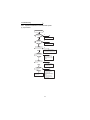
OUTLINE .................................................................................................... 1
1.1
1.2
Basic configuration and connection of peripheral devices........................................ 2
Structure ................................................................................................................... 4
2.1
2.2
2.3
2.4
Installation of the inverter ......................................................................................... 6
Connection diagram, encoder cable, PU connector ................................................. 7
Setting the motor .................................................................................................... 20
Precautions for use of the vector inverter............................................................... 22
3.1
3.2
3.3
Checks prior to test run .......................................................................................... 23
Basic operation (Speed setting, run, speed meter adjustment).............................. 23
Names and functions of the control panel .............................................................. 27
4.1
4.2
4.3
4.4
4.5
4.6
4.7
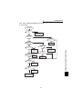
Speed control operation ......................................................................................... 33
Torque control operation ........................................................................................ 38
Position control operation ....................................................................................... 44
Control mode switchover timing ............................................................................. 45
Easy gain tuning ..................................................................................................... 47
Online auto tuning .................................................................................................. 50
Biases and gains of speed setting terminals
(Pr. 902 to Pr. 905, Pr. 917 to Pr. 920)................................................................... 51
1
2
2 INSTALLATION AND WIRING ................................................................... 6
2
3
3 RUN AND OPERATION ........................................................................... 23
4 CONTROL ................................................................................................ 33
4
5
5 PARAMETERS ......................................................................................... 54
5.1
5.2
Function list (Simple mode parameters)................................................................. 54
Function list (Extended function parameters) ......................................................... 58
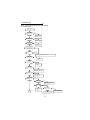
6.1
6.2
6.3
6.4
Errors (Alarms) ....................................................................................................... 74
Correspondences between digital and actual characters....................................... 84
Resetting the inverter ............................................................................................. 84
Troubleshooting...................................................................................................... 85
7.1
7.2
7.3
7.4
Check items............................................................................................................ 96
Replacement of parts ............................................................................................. 98
Inverter replacement............................................................................................. 100
Measurement of main circuit voltages, currents and powers ............................... 101
8.1
8.2
8.3
Model specifications ............................................................................................. 103
Common specifications ........................................................................................ 106
Outline dimension drawings ................................................................................. 107
6 ERRORS AND PROTECTIVE FUNCTIONS ............................................ 74
IB(NA)-0600064-E(0611)MEE Printed in Japan
Specifications subject to change without notice.
INSTRUCTION MANUAL (BASIC)
HEAD OFFICE:TOKYO BLDG MARUNOUCHI TOKYO 100-8310
6
7 PRECAUTIONS FOR MAINTENANCE AND INSPECTION .................... 96
7
8 SPECIFICATIONS ................................................................................. 103
8
This Instruction Manual (basic) provides handling information and precautions for use of the equipment.
Please forward this Instruction Manual (basic) to the end user.
This section is specifically about safety matters
Do not attempt to install, operate, maintain or inspect the inverter until you have read through the Instruction Manual and appended
documents carefully and can use the equipment correctly. Do not use the inverter until you have a full knowledge of the equipment, safety
information and instructions. In this Instruction Manual, the safety instruction levels are classified into "WARNING" and "CAUTION".
WARNING
CAUTION
Assumes that incorrect handling may cause hazardous conditions, resulting in death or severe injury.
Assumes that incorrect handling may cause hazardous conditions, resulting in medium or slight
injury, or may cause physical damage only.
CAUTION level may lead to a serious consequence according to conditions. Please follow the instructions of
Note that even the
both levels because they are important to personnel safety.
1. Electric Shock Prevention
WARNING
z While power is on or when the inverter is running, do not open the front cover. You may get an electric shock.
z Do not run the inverter with the front cover or wiring cover removed. Otherwise, you may access the exposed high-voltage terminals
or the charging part of the circuitry and get an electric shock.
z Even If power is off, do not remove the front cover except for wiring or periodic inspection. You may access the charged inverter
circuits and get an electric shock.
z Before starting wiring or inspection, check to make sure that the inverter power indicator lamp is off, wait for at least 10 minutes after
the power supply has been switched off, and check that there are no residual voltage using a tester or the like. The capacitor is
charged with high voltage for some time after power off and it is dangerous.
z This inverter must be earthed (grounded). Earthing (Grounding) must conform to the requirements of national and local safety
regulations and electrical codes. (NEC section 250, IEC 536 class 1 and other applicable standards).
z Any person who is involved in wiring or inspection of this equipment should be fully competent to do the work.
z Always install the inverter before wiring. Otherwise, you may get an electric shock or be injured.
z Perform setting dial and key operations with dry hands to prevent an electric shock.
z Do not subject the cables to scratches, excessive stress, heavy loads or pinching. Otherwise, you may get an electric shock.
z Do not change the cooling fan while power is on. It is dangerous to change the cooling fan while power is on.
2. Fire Prevention
CAUTION
z Install the inverter on an incombustible wall without holes, etc. Mounting it to or near combustible material can cause a fire.
z If the inverter has become faulty, switch off the inverter power. A continuous flow of large current could cause a fire.
z When a brake resistor is used, use an alarm signal to switch power off. Otherwise, the brake resistor will overheat abnormally due to
a brake transistor or other fault, resulting in a fire.
z Do not connect a resistor directly to the DC terminals P, N. This could cause a fire.
3.Injury Prevention
CAUTION
z Apply only the voltage specified in the instruction manual to each terminal to prevent damage etc.
z Ensure that the cables are connected to the correct terminals. Otherwise damage etc. may occur.
z Always make sure that polarity is correct to prevent damage etc.
z While power is on and for some time after power-off, do not touch the inverter or brake resistor as they are hot and you may get burnt.
4. Additional Instructions
Also note the following points to prevent an accidental failure, injury, electric shock, etc.
1) Transportation and installation
CAUTION
Environment
z When carrying products, use correct lifting gear to prevent injury.
z Do not stack the inverter boxes higher than the number recommended.
z Ensure that installation position and material can withstand the weight of the inverter. Install according to the information in the
instruction manual.
z Do not operate if the inverter is damaged or has parts missing.
z When carrying the inverter, do not hold it by the front cover; it may fall off or fail.
z Do not stand or rest heavy objects on the inverter.
z Check the inverter mounting orientation is correct.
z Prevent screws, wire fragments, other conductive bodies, oil or other flammable substances from entering the inverter.
z Do not drop the inverter, or subject it to impact
z Use the inverter under the following environmental conditions:
Ambient temperature
-10°C to +50°C (non-freezing)
Ambient humidity
90%RH or less (non-condensing)
Storage temperature
-20°C to +65°C*
Ambience
Indoors (free from corrosive gas, flammable gas, oil mist, dust and dirt)
Maximum 1000m above sea level for standard operation.
Altitude, vibration
After that derate by 3% for every extra 500m up to 2500m (91%). 5.9m/s2 or less
*Temperature applicable for a short time, e.g. in transit.
A-1
2) Wiring
CAUTION
z Do not fit capacitive equipment such as power factor correction capacitor, surge suppressor or radio noise filter (option FR-BIF) to
the inverter output side.
z The connection orientation of the output cables (terminals U, V, W) to the motor will affect the direction of rotation of the motor.
3) Trial run
CAUTION
z Check all parameters, and ensure that the machine will not be damaged by a sudden start-up.
4) Operation
WARNING
z When you have chosen the retry function, stay away from the equipment as it will restart suddenly after an alarm stop.
z Since the [STOP] key is valid only when functions are set (refer to page 62) provide a circuit and switch separately to make an
emergency stop (power off, mechanical brake operation for emergency stop, etc).
z Make sure that the start signal is off before resetting the inverter alarm. A failure to do so may restart the motor suddenly.
z The load used should be a three-phase induction motor only. Connection of any other electrical equipment to the inverter output may
damage the equipment.
z Do not modify the equipment.
z Do not perform parts removal which is not instructed in this manual. Doing so may lead to fault or damage of the inverter.
CAUTION
z The electronic thermal relay function does not guarantee protection of the motor from overheating.
z Do not use a magnetic contactor on the inverter input for frequent starting/stopping of the inverter.
z Use a noise filter to reduce the effect of electromagnetic interference. Otherwise nearby electronic equipment may be affected.
z Take measures to suppress harmonics. Otherwise power supply harmonics from the inverter may heat/damage the power capacitor
and generator.
z When a 400V class motor is inverter-driven, please use an insulation-enhanced motor or measures taken to suppress surge
voltages. Surge voltages attributable to the wiring constants may occur at the motor terminals, deteriorating the insulation of the
motor.
z When parameter clear or all clear is performed, each parameter returns to the factory setting. Each parameter returns to the factory
setting.
z The inverter can be easily set for high-speed operation. Before changing its setting, fully examine the performances of the motor and machine.
z In addition to the inverter's holding function, install a holding device to ensure safety.
z Before running an inverter which had been stored for a long period, always perform inspection and test operation. In addition to the
inverter's holding function, install a holding device to ensure safety.
5) Emergency stop
CAUTION
z Provide a safety backup such as an emergency brake which will prevent the machine and equipment from hazardous conditions if
the inverter fails.
z When the breaker on the inverter input side trips, check for the wiring fault (short circuit), damage to internal parts of the inverter, etc.
Identify the cause of the trip, then remove the cause and power on the breaker.
z When the protective function is activated, take the appropriate corrective action, then reset the inverter, and resume operation.
6) Maintenance, inspection and parts replacement
CAUTION
z Do not carry out a megger (insulation resistance) test on the control circuit of the inverter.
7) Disposing of the inverter
CAUTION
z Treat as industrial waste.
8) General instructions
Many of the diagrams and drawings in this Instruction Manual (basic) show the inverter without a cover, or partially open. Never operate
the inverter in this manner. Always replace the cover and follow this Instruction Manual (basic) when operating the inverter.
<Abbreviations>
DU: Control panel (FR-DU04-1)
PU: Control panel (FR-DU04-1) and parameter unit (FR-PU04V)
Inverter: Mitsubishi vector inverter FR-V500 series
FR-V500: Mitsubishi vector inverter FR-V500 series
Pr.: Parameter number
PU operation: Operation using the PU (FR-DU04-1/FR-PU04V)
External operation: Operation using the control circuit signals
Combined operation: Operation using both the PU (FR-DU04-1/FR-PU04V) and external operation
<Trademarks>
CC-Link is a registered trademark of CC-Link Partner Association.
Other company and product names herein are the trademarks or registerd trademarks of their respective owners.
A-2
1
OUTLINE
Harmonic Suppression Guideline
All models of general-purpose inverters used by specific consumers are covered by "Harmonic suppression
guideline for consumers who receive high voltage or special high voltage".
(For further details, refer to
Instruction Manual (detailed).)
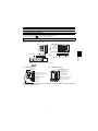
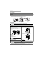
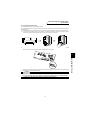
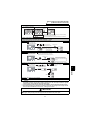
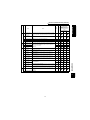
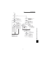
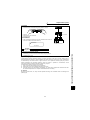
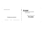
Product check and name of parts
Unpack the inverter and check the capacity plate on the front cover and the rating plate on the inverter side face to
ensure that the product agrees with your order, an accessory L-shaped jumper (Refer to page 15 for connection
method.) is included, and the inverter is intact.
Plates
Rating plate
Inverter type
Input rating
Output rating
.
Serial number
1
Capacity plate
Inverter type
FR - V520 - 1.5 K
Symbol Voltage class
Three-phase 200V class
V520
V540
Three-phase 400V class
Serial number
Inverter
capacity
(kW)
Terminal 5 dedicated L-shaped jumper × 1 (supplied)
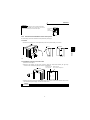
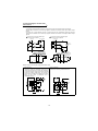
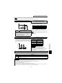
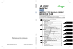
(2)
(1) Front view
POWER lamp
ALARM lamp
Without front cover
Control panel (FR-DU04-1)
PU connector
(Provided with modular jack
type relay connector)
(For use with RS-485 cable
communication)
Brake resistor* (Fitted to the back)
Accessory cover
Modular jack type relay
connector compartment
Wiring port cover for option
(DATA PORT)
Front cover
Rating plate
Inboard option mounting positions
Control circuit terminal block
Main circuit terminal block
Wiring cover
Capacity plate
*The 5.5K or less inverter is equipped with a built-in brake resistor and the 15K or less inverter is equipped
with a built-in brake transistor.
1
OUTLINE
Inverter type
Basic configuration and connection
of peripheral devices
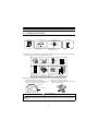
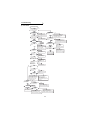
1.1 Basic configuration and connection of peripheral devices
1.1.1
Basic configuration
Power supply
Use within the permissible power supply specifications of the inverter. (Refer to page 103.)
(MCCB)
or
(ELB)
Moulded case circuit breaker (MCCB) or earth leakage circuit breaker (ELB)
The breaker must be selected carefully since an in-rush current flows in the inverter at power-on.
(Refer to page 3.)
Magnetic contactor
Install the magnetic contactor to ensure safety. (For details, refer to the Instruction Manual (detailed).)
Do not use this magnetic contactor to start and stop the inverter. Doing so will cause the inverter life to
be shorten. (Refer to page 3.)
(MC))
Power factor improving reactor
AC reactor
(FR-HAL/BAL)
A reactor (option) should be used when the power factor is to be improved or when the inverter is
installed near a large power supply system (1000kVA or more and wiring distance is within 10m). The
inverter may be damaged if you do not use reactors.
Make selection carefully. (Refer to page 3.)
• DC reactor (FR-HEL/BEL), AC reactor (FR-HAL/BAL)
(Caution) Remove the jumpers across terminals P-P1 to connect to the DC reactor.
Noise filter
Install a noise filter to reduce the electromagnetic noise generated from the inverter.
• Line noise filter (FR-BSF01) (FR-BLF)
Effective in the range from about 1MHz to 10MHz. When more wires are passed through, a more
effective result can be obtained. (Note that the number of wires run through is limited when fitting to
the output side.)
• Radio noise filter (FR-BIF)
Effective in reducing the noises in the AM radio frequency band. Dedicated filter for the input side.
Line noise
filter
Radio noise
filter
Power factor
improving
reactor
Brake
resistor
(FR-ABR)
P
Inverter
Inverter
FR-V500
RST
P1
P
PR
P
Brake unit
N
The life of the inverter is influenced by ambient temperature. The ambient temperature should be
as low as possible within the permissible range. This must be noted especially when the inverter
is installed in an enclosure. (Refer to page 6.)
Wrong wiring might lead to damage of the inverter. The control signal lines must be kept fully away
from the main circuit to protect them from noise. (Refer to page 7.)
Brake resistor
(Caution) • Remove the jumpers across terminals PR-PX to connect to the inverter.
• Set "1" in Pr. 30 "regenerative function selection".
• Set Pr. 70 "special regenerative brake duty" as follows:
7.5K or less . . . . 10%
11K or more . . . 6%
Brake unit
(Caution)
Remove the jumpers across terminals PR-PX to connect to the inverter.
Power regeneration common converter (FR-CV)
Line noise
filter
Encoder cable
(Caution) • Remove the jumpers across terminals R-R1 and S-S1.
• For a terminal to be connected to the RDYB signal of the FR-CV, set "10" (X10 signal) in
any of Pr. 180 to Pr. 183 and Pr. 187(input terminal function selection).
• Set "2" in Pr. 30 "regenerative function selection".
• Select the converter one rank higher in capacity than the inverter.
Selection example: FR-V520-7.5K→FR-CV-11K, FR-V520-15K→FR-CV-18.5K (When
connecting two inverters to one FR-CV, the capacity is 11K + 18.5K = 29.5K. Therefore,
select FR-CV-30K.)
Motor
z Dedicated motor (Refer to page 103.)
This is a highly environmentally-resistant motor based on a totally-enclosed squirrel-cage induction
motor designed for the vector inverter. Select the motor that matches the inverter capacity.
Encoder
For the encoder dedicated motor, refer to page 12.
Devices connected to the output
Earth (Ground)
Do not install a power factor correction capacitor, surge suppressor or radio noise filter (FR-BIF
option) on the output side of the inverter.
When installing a moulded case circuit breaker on the output side of the inverter, contact each
manufacturer for selection of the moulded case circuit breaker.
Earth (Ground)
To prevent an electric shock, always earth (ground) the motor and inverter. For reduction of induction
noise from the power line of the inverter, it is recommended to wire the earth (ground) cable by
returning it to the earth (ground) terminal of the inverter.
(
For details of noise reduction techniques, refer to the Instruction Manual (detailed).)
CAUTION
• Do not fit capacitive equipment such as power factor correction capacitor, radio noise filter (FR-BIF option) or surge
suppressor to the output side of the inverter. This will cause the inverter to trip or the capacitor and surge suppressor to
be damaged. If any of the above devices are connected, immediately remove them. (If the FR-BIF radio noise filter is
connected, switching power off during motor operation may result in "E.UVT". In this case, connect the radio noise filter
on the primary side of the magnetic contactor.)
• Electromagnetic wave interference
The input/output (main circuit) of the inverter includes high frequency components, which may interfere with the
communication devices (such as AM radios) used near the inverter. In this case, install the FR-BIF optional radio noise
filter (for use on the input side only) or FR-BSF01 or FR-BLF line noise filter to minimize interference.
• For details of peripheral devices, refer to manuals of each option and peripheral devices.
2
Basic configuration and connection
of peripheral devices
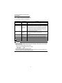
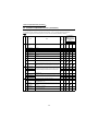
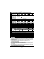
1.1.2
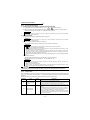
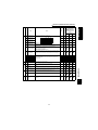
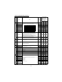
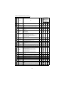
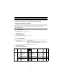
Selection of peripheral devices
Check the motor applicable to the inverter you purchased. Appropriate peripheral devices need to be selected
according to the motor capacity. Refer to the list below and prepare appropriate peripheral devices.
200V class
*1
1.5
2.2
3.7
5.5
7.5
11
15
18.5
22
30
37
45
55
Applicable
Inverter
Type
Standard
FR-V520-1.5K
FR-V520-2.2K
FR-V520-3.7K
FR-V520-5.5K
FR-V520-7.5K
FR-V520-11K
FR-V520-15K
FR-V520-18.5K
FR-V520-22K
FR-V520-30K
FR-V520-37K
FR-V520-45K
FR-V520-55K
30AF 15A
30AF 20A
30AF 30A
50AF 50A
100AF 60A
100AF 75A
225AF 125A
225AF 150A
225AF 175A
225AF 225A
400AF 250A
400AF 300A
400AF 400A
With power factor
improving reactor
30AF 15A
30AF 15A
30AF 30A
50AF 40A
50AF 50A
100AF 75A
100AF 100A
225AF 125A
225AF 150A
225AF 175A
225AF 225A
400AF 300A
400AF 350A
Power Factor
Improving AC
Reactor
Power Factor
Improving DC
Reactor
Magnetic
Contactor (MC)
FR-HAL/BAL-1.5K
FR-HAL/BAL-2.2K
FR-HAL/BAL-3.7K
FR-HAL/BAL-5.5K
FR-HAL/BAL-7.5K
FR-HAL/BAL-11K
FR-HAL/BAL-15K
FR-HAL/BAL-22K
FR-HAL/BAL-22K
FR-HAL/BAL-30K
FR-HAL/BAL-37K
FR-HAL/BAL-45K
FR-HAL/BAL-55K
FR-HEL/BEL-1.5K
FR-HEL/BEL-2.2K
FR-HEL/BEL-3.7K
FR-HEL/BEL-5.5K
FR-HEL/BEL-7.5K
FR-HEL/BEL-11K
FR-HEL/BEL-15K
FR-HEL/BEL-18.5K
FR-HEL/BEL-22K
FR-HEL/BEL-30K
FR-HEL/BEL-37K
FR-HEL/BEL-45K
FR-HEL/BEL-55K
S-N10
S-N10
S-N20, N21
S-N25
S-N35
S-N50
S-N65
S-N80
S-N95
S-N125
S-N150
S-N180
S-N220
Power Factor
Improving AC
Reactor
Power Factor
Improving DC
Reactor
Magnetic
Contactor (MC)
FR-HAL/BAL-H1.5K
FR-HAL/BAL-H2.2K
FR-HAL/BAL-H3.7K
FR-HAL/BAL-H5.5K
FR-HAL/BAL-H7.5K
FR-HAL/BAL-H11K
FR-HAL/BAL-H15K
FR-HAL/BAL-H22K
FR-HAL/BAL-H22K
FR-HAL/BAL-H30K
FR-HAL/BAL-H37K
FR-HAL/BAL-H45K
FR-HAL/BAL-H55K
FR-HEL/BEL-H1.5K
FR-HEL/BEL-H2.2K
FR-HEL/BEL-H3.7K
FR-HEL/BEL-H5.5K
FR-HEL/BEL-H7.5K
FR-HEL/BEL-H11K
FR-HEL/BEL-H15K
FR-HEL/BEL-H18.5K
FR-HEL/BEL-H22K
FR-HEL/BEL-H30K
FR-HEL/BEL-H37K
FR-HEL/BEL-H45K
FR-HEL/BEL-H55K
S-N10
S-N10
S-N20, N21
S-N20, N21
S-N20, N21
S-N25
S-N35
S-N50
S-N50
S-N65
S-N80
S-N95
S-N125
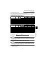
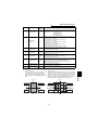
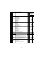
400V class
Motor
Output
(kW)
*1
1.5
2.2
3.7
5.5
7.5
11
15
18.5
22
30
37
45
55
Applicable
Inverter
Type
Moulded Case Circuit
Breaker (MCCB)
or Earth Leakage Circuit
Breaker (ELB*1*2)
Standard
FR-V540-1.5K
FR-V540-2.2K
FR-V540-3.7K
FR-V540-5.5K
FR-V540-7.5K
FR-V540-11K
FR-V540-15K
FR-V540-18.5K
FR-V540-22K
FR-V540-30K
FR-V540-37K
FR-V540-45K
FR-V540-55K
30AF 10A
30AF 15A
30AF 20A
30AF 30A
30AF 30A
50AF 50A
100AF 60A
100AF 75A
100AF 100A
225AF 125A
225AF 150A
225AF 175A
225AF 200A
With power factor
improving reactor
30AF 10A
30AF 10A
30AF 15A
30AF 20A
30AF 30A
50AF 40A
50AF 50A
100AF 60A
100AF 75A
100AF 100A
225AF 125A
225AF 150A
225AF 175A
*1 Select the MCCB according to the inverter power supply capacity.
MCCB
INV
IM
Install one MCCB per inverter.
For installations in the United States or Canada, use the fuse certified by the UL and cUL.
MCCB
INV
IM
(Refer to page 115.)
*2 When the breaker on the inverter primary side trips, check for the wiring fault (short circuit), damage to internal parts of the
inverter, etc. Identify the cause of the trip, then remove the cause and power on the breaker.
3
1
OUTLINE
Motor
Output
(kW)
Moulded Case Circuit
Breaker (MCCB)
or Earth Leakage Circuit
Breaker (ELB*1*2)
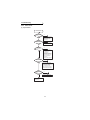
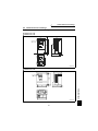
Structure
1.2 Structure
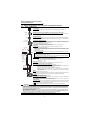
1.2.1
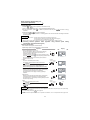
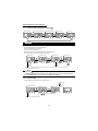
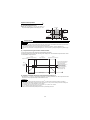
Removal and reinstallation of the front cover
FR-V520-1.5K to 7.5K, FR-V540-1.5K to 5.5K
z Removal
1)
2)
Hold both sides of the front cover top and push the front cover down.
Hold down the front cover and pull it toward you to remove.
(The front cover may be removed with the PU (FR-DU04-1/FR-PU04V) on.)
Hook
Inverter
Front cover
z Reinstallation
1) Insert the hooks at the bottom of the front cover into the sockets of the inverter.
2) Using the hooks as supports, securely press the front cover against the inverter.
CAUTION
When the control panel is fitted to the removed front cover, reinstall the front cover after removing the
control panel.
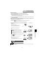
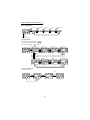
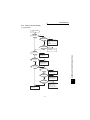
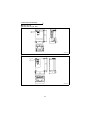
FR-V520-11K, 15K, FR-V540-7.5K to 18.5K
• Removal
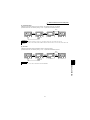
FR-V520-18.5K to 55K, FR-V540-22K to 55K
• Removal
1) Remove the installation screw at the top of the front cover.
2) Hold both ends of the front cover top.
3) Pull the front cover toward you to remove.
(The front cover may be removed with the control panel
attached.)
1) Remove the installation screws at the top of the front cover.
• Reinstallation
1) Fix the front cover with the installation screws.
• Reinstallation
1) Insert the hooks at the front cover bottom into the sockets
of the inverter.
2) Using the hooks as supports, securely press the front
cover against the inverter.
3) Fix the front cover with the top screw.
CAUTION
When the control panel is fitted to the removed
front cover, reinstall the front cover after
removing the control panel.
REMARKS
The 45K and 55K have two front covers, which are fixed
with eight screws.
CAUTION
1. Fully make sure that the front cover has been reinstalled securely.
2. The same serial number is printed on the capacity plate of the front cover and the rating plate of the
inverter. Before reinstalling the front cover, check the serial numbers to ensure that the cover
removed is reinstalled to the inverter from where it was removed.
4
Structure
REMARKS
• Removal of the wiring port cover for option (DATA PORT)
Push the DATA PORT from the back of the front cover to
remove before fitting the communication option.
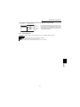
1.2.2
Wiring port cover
for option
(DATA PORT)
.
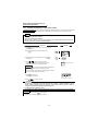
Removal and reinstallation of the control panel
To ensure safety, remove and reinstall the control panel after powering off.
z Removal
Hold down the top button of the control panel and pull the control panel toward you to remove.
Removal
Reinstallation
OUTLINE
1
When reinstalling the control panel, insert it straight and reinstall it securely.
z Reinstallation using the connection cable
1) Remove the control panel.
2) Disconnect the modular jack type relay connector. (Place the disconnected modular jack type relay
connector in the modular jack type relay connector compartment.)
Modular jack type
relay connector
Modular jack type
relay connector compartment
3) Securely plug one end of the connection cable into the PU connector of the inverter and the other end into
the control panel. (Refer to page 19 for the connection cable.)
CAUTION
Install the control panel only when the front cover is on the inverter.
5
Installation of the inverter
2
INSTALLATION AND WIRING
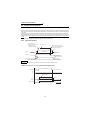
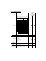
2.1 Installation of the inverter
z Install the inverter under the following conditions.
Vertical mounting
10cm or more
Measurement
position
Inverter
5cm
Measurement
position
Vertical
5cm
5cm
or more *
5cm
5cm
or more *
5cm Inverter
or more
10cm or more
Temperature: -10°C to 50°C
Humidity: 90%RH maximum.
Leave enough clearances and take
cooling measures.
Clearances (side)
Clearances (front)
Ambient temperature and humidity
These clearances are also necessary for
changing the cooling fan
*1cm or more for 2.2K or less.
z The inverter consists of precision mechanical and electronic parts. Never install or handle it in any of the following
conditions as doing so could cause an operation fault or failure.
.
Vibration
(5.9m/s 2 or more)
Direct sunlight
High temperature,
high humidity
Horizontal placement
.
.
Vertical mounting
(When installing two or
more inverters, install
them in parallel.)
Transportation by
holding front cover.
Oil mist, flammable gas,
corrosive gas, fluff,
dust etc.
Mounting on
combustible material
z Wiring cover and handling (15K or less for the 200V class, 18.5K or less for the 400V class)
1)
When cable conduits are not connected
2)
Cut the protective bushes of the wiring cover with
nippers or a cutter before running the cables.
When cable conduits are connected
Remove the corresponding protective bushes and
connect the cable conduits.
Wiring cover
Protective bush
WARNING
Do not remove the protective bushes when cable conduits are not connected. Otherwise, the cable
sheathes may be scratched by the wiring cover edges, resulting in a short circuit or earth (ground)
fault.
6
Connection diagram, encoder cable,
PU connector
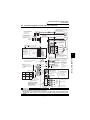
2.2 Connection diagram, encoder cable, PU connector
2.2.1
Connection diagram
(Dedicated Motor: SF-V5RU)
Avoid frequent ON-OFF.
Repeated inrush currents at
power-on will shorten the
converter life.
(Switching life is 100,000)
Three-phase
AC power
supply
MCCB
R
MC
OCR
B
T
C
Vector inverter
(FR-V500)
MCCB MC
U
R
V
S
W
T
R1
OH
SD
S1
PA
Take care not to
short terminals
PC-SD.
Terminals DI1 to
DI4 and STR vary
in function with
the input terminal
function selection
(Pr. 180 to Pr. 183,
Pr. 187) settings.
External transistor common
24VDC power supply
Contact input common (source)
Forward rotation start
Reverse rotation start
Reset
PAR
PB
PBR
PC
STF
STR
RES
DI1(RL)
PZ
PZR
PG
SD
DI2(RM)
Digital input
signal 4
You can select between sink and source
Refer to page 17 for details.
P1
P
SOURCE
R
10E(+10V)
1
Torque
Control
Speed
limit
command
N
2 (0 to +10V)
When using the motor
not equipped with a
thermal protector,
Thermal
set Pr. 9 and Pr. 876
protector
= "0"
G1
G2
A
B
C
D
F
E ncoder
G
S
R
N
DO2(SU)
DO3(IPF)
1( + 10V)
3( + 10V)
C
-10V
Prepare a +10V external power
supply for terminals 1, 3.
Change the jumper connector and
parameter settings according to
the PLG specifications.
Refer to page 12 for details.
Any of three different
signals can be selected
using the parameter.
(Open collector output)
Open collector output
SE common
A
B
External
power supply
Jumper
(When using the
FR-HEL/BEL, remove
this jumper.)
FR-HEL/BEL power Across terminals P
factor improving DC
and PR, connect only
reactor (option)
the optional,
FR-ABR high-duty recommended brake
resistor. In addition,
brake resistor
never short these
(option)
R
terminals.
Jumper (Remove this jumper
Terminal PR is
when using the FR-ABR.)
provided for the 15K
Terminal PX is provided for
or less.
the 5.5K or less.
DO1(RUN)
5
Analog
input
common
Analog command
input
Torque
command
PR
3 2
+10V
3
IM
W
E
When the motor used is not the vector
inverter motor, the pin numbers are different.
The N pin of the PLG designed for vector
inverter motor is case-earthed.
PX
Speed setting potentiometer
1/2W 1k
2W 1k is recommended for use
when speed setting is changed
frequently.
Torque
limit
command
Match phase sequence.
REMARKS
SINK
10E, 2, 5
U
V
DI4(RT)
SD Contact
Control input signals (no voltage input allowed)
Terminal
FAN
DI3(RH)
input
common
Speed
Control
Main
speed
command
A
S
5V
12V
24V DA1
EXT
DA2
Differential
Complimentary
PU
connector
5
Alarm output
(Contact output)
(+) +10V
12 bits
1ch
(+) 0 to 10V
12 bits
1ch
Terminals DO1 to DO3
and ABC vary in function
with the output terminal
function selection
(Pr. 190 to Pr. 192,
Pr. 195) settings.
Load impedance of 10kΩ or mor
Analog signal output
(-)
Main circuit terminal
(Analog output common)
Control circuit terminal
CAUTION
• To prevent a malfunction caused by noise, separate the signal cables more than 10cm (3.94 inches)
from the power cables.
• During wiring, do not leave wire offcuts in the inverter.
Wire offcuts can cause an alarm, failure or malfunction. Always keep the inverter clean. When drilling
mounting holes in an enclosure etc., take care not to allow chips and other foreign matter to enter the
inverter.
7
2
INSTALLATION AND WIRING
Verify the power specification
of the motor cooling when
performing wiring.
Refer to page 103.
Match phase sequence.
(Fan should have intake rotation.)
Connection diagram, encoder cable,
PU connector
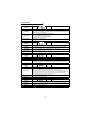
2.2.2
Main circuit terminal specifications
(1) Specification of main circuit terminal
Terminal Symbol
Terminal Name
DC reactor
connection
Built-in brake circuit
connection
Earth (Ground)
For earthing (grounding) the inverter chassis. Must be earthed (grounded).
R, S, T
AC power input
U, V, W
Inverter output
R1, S1
Power supply for
control circuit
P, PR
Brake resistor
connection
P, N
Brake unit
connection
P, P1
PR, PX
Description
Connect to the commercial power supply.
Keep these terminals open when using the high power factor converter (FRHC) or power regeneration common converter (FR-CV).
Connect a three-phase squirrel-cage motor or Mitsubishi dedicated motor.
Connected to the AC power supply terminals R and S. To retain the alarm
display and alarm output or when using the high power factor converter (FRHC) or power regeneration common converter (FR-CV), remove the jumpers
from terminals R-R1 and S-S1 and apply external power to these terminals.
Do not turn off the power supply for control circuit (R1, S1) with the main
circuit power (R, S, T) on. Doing so may damage the inverter. The circuit
should be configured so that the main circuit power (R, S, T) is also turned off
when the power supply for control circuit (R1, S1) is off.
15K or less: 60VA, 18.5K to 55K: 80VA
Disconnect the jumper from terminals PR-PX (5.5K or less) and connect the
optional brake resistor (FR-ABR) across terminals P-PR.
For the 15K or less, connecting the resistor further provides regenerative
braking power.
Connect the optional FR-BU type brake unit, BU type brake unit, power
regeneration common converter (FR-CV) or high power factor converter
(FR-HC).
Disconnect the jumper from terminals P-P1 and connect the optional DC
reactor (FR-HEL/BEL).
When the jumper is connected across terminals PX-PR (factory setting),
the built-in brake circuit is valid. (Provided for the 5.5K or less.)
CAUTION
• The inverter will be damaged if power is applied to the inverter output terminals (U, V, W). Never
perform such wiring.
• When connecting the dedicated external brake resistor (FR-ABR), remove jumpers across terminals
PR-PX (5.5K or less).
Set "1" in Pr. 30 "regenerative function selection".
Set Pr. 70 "special regenerative brake duty" as follows:
7.5K or less . . . . . . . . 10%
11K or more . . . . . . . 6%
Refer to the Instruction Manual (detailed) for details.
• When connecting the brake unit (FR-BU, BU type), remove jumpers across terminals PR-PX (5.5K or
less). Refer to the Instruction Manual (detailed) for details.
8
Connection diagram, encoder cable,
PU connector
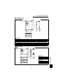
(2) Terminal arrangement of the main circuit terminal
In the main circuit of the inverter, the terminals are arranged as shown below:
200V class
FR-V520-1.5K, 2.2K
Jumpers
FR-V520-18.5K
Jumpers
Screw size (M4)
Jumpers
Charge lamp
R
S
T
U
V
W
N
P
P1
R1 S1
R1 S1
PR
R
PX
Charge lamp
Screw size (M4)
S
Screw size (M8)
IM
Power supply
Motor
R
Screw size (M4)
S
T
U
V
W
P1
N
P
Jumper
IM
Screw size (M6)
FR-V520-3.7K, 5.5K, 7.5K
FR-V520-22K
Jumpers
Jumpers
Charge lamp
R
R
S
Screw size (M4)
S
Screw size (M8)
Charge lamp
Jumper
Screw size (M5)
R1 S1
R1 S1
S
R
U
T
V
R
W
U
T
S
N
W
V
P1
P
PR PX
Screw size (M6)
IM
Screw size (M5)
7.5K is not provided with the PX terminal and PX-PR jumper.
FR-V520-11K
Screw size (M4)
Screw size (M6)
T
Jumpers
Jumpers
Charge lamp
R1 S1
PR
S
FR-V520-30K, 37K
R1 S1
Screw size (M5)
R
U
P
Jumper
IM
N
P1
V
Charge
lamp
R
Screw size (M4)
S
R
S
Screw size (M10)
W
N
P1
P
R
Jumper
IM
S
U
T
V
N
W
P
Jumper
IM
Screw size (M6)
P1
Screw size (M8)
FR-V520-15K
FR-V520-45K, 55K
Screw size (M4)
Jumpers
Jumpers
Charge lamp
Screw size (M5)
PR
Screw size (M8)
R
S
T
U
R1 S1
R1 S1
V
IM
Charge
lamp
W
N
R
R
S
Screw size (M4)
S
Screw size (M12)
P1
R
P
Jumper
S
T
U
V
W
N
P1
IM
Screw size (M8)
Screw size (M6)
9
P
Jumper
2
INSTALLATION AND WIRING
Screw size (M4)
Connection diagram, encoder cable,
PU connector
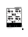
400V class
FR-V540-1.5K, 2.2K
FR-V540-18.5K
Jumpers
Jumpers
Jumpers
Screw size (M4)
Charge lamp
R1 S1
R
S
U
T
V
W
P1
N
R
R1 S1
S
Screw size (M6)
PX
Charge lamp
IM
Power supply
Screw size (M4)
PR
P
R
S
T
U
V
W
N
P1
Motor
IM
Screw size (M4)
P
Jumper
Screw size (M6)
FR-V540-3.7K, 5.5K
FR-V540-22K
Jumpers
Screw size (M4)
Jumpers
Charge lamp
R1 S1
R
R1 S1
S
R
Charge lamp
Jumper
R
Screw size (M4)
S
T
N P1
U
V
S
Screw size (M6)
W
R
S
T
U
V
N
W
P1
P
Jumper
IM
P PR PX
Screw size (M6)
IM
Screw size (M4)
Screw size (M4)
FR-V540-7.5K, 11K, 15K
FR-V540-30K, 37K, 45K, 55K
Jumpers
Screw size (M4)
Jumpers
Charge lamp
R1 S1
R1 S1
Screw size (M5)
PR
Charge
lamp
Screw size (M6)
R
R
S
S
T
U
V
W
N
P1
S
Screw size (M8)
R
R
Screw size (M4)
S
T
U
V
W
P
N
P1
P
Jumper
IM
Jumper
IM
Screw size (M8)
Screw size (M6)
CAUTION
• Make sure the power cables are connected to the R, S, T of the inverter. Never connect the power cable
to the U, V, W of the inverter. (Phase need not be matched.)
• Connect the motor to U, V, W. At this time, turning on the forward rotation switch (signal) rotates the
motor in the counterclockwise direction when viewed from the motor shaft.
10
Connection diagram, encoder cable,
PU connector
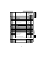
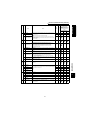
(3) Cables and wiring length
Select the recommended cable size to ensure that a voltage drop will be 2% max.
If the wiring distance between the inverter and motor is long, the motor torque will decrease due to the voltage drop of the
main circuit cable especially at high-frequency output. The encoder signal will also be affected by the voltage drop.
The following selection example assumes the wiring length of 20m.
200V class (When input power supply is 220V)
Applicable Inverter
Type
Terminal
Screw Size
FR-V520-1.5K, 2.2K
FR-V520-3.7K
FR-V520-5.5K
FR-V520-7.5K
FR-V520-11K
FR-V520-15K
FR-V520-18.5K, 22K
FR-V520-30K
FR-V520-37K
FR-V520-45K
FR-V520-55K
HIV Cables
Crimping
Tightening
2
Terminals
Torque
AWG
mm
N·m
R, S, T U, V, W R, S, T U, V, W R, S, T U, V, W
M4
M5
M5
M5
M6
M8
M8
M10
M10
M12
M12
1.5
2.5
2.5
2.5
4.4
7.8
7.8
14.7
14.7
24.5
24.5
2-4
2-4
3.5-5
3.5-5
5.5-5
5.5-5
14-5
8-5
14-6
14-6
22-8
22-8
38-8
38-8
60-10 60-10
100-10 100-10
100-12 100-12
150-12 150-12
2
3.5
5.5
14
14
22
38
60
100
100
150
2
3.5
5.5
8
14
22
38
60
100
100
150
14
14
12
12
10
10
6
8
6
6
4
4
2
2
1/0
1/0
4/0
4/0
4/0
4/0
MCM300 MCM300
PVC Cables
mm2
R, S, T U, V, W
2.5
6
10
16
25
35
50
70
120
150
240
2.5
4
6
10
16
25
35
70
95
120
185
400V class (When input power supply is 440V)
FR-V540-1.5K to 3.7K
FR-V540-5.5K
FR-V540-7.5K
FR-V540-11K
FR-V540-15K
FR-V540-18.5K
FR-V540-22K
FR-V540-30K
FR-V540-37K
FR-V540-45K
FR-V540-55K
Terminal
Screw Size
HIV Cables
PVC Cables
Crimping
Tightening
2
Terminals
AWG
Torque
mm2
mm
N·m
R, S, T U, V, W R, S, T U, V, W R, S, T U, V, W R, S, T U, V, W
M4
M4
M6
M6
M6
M6
M6
M8
M8
M8
M8
1.5
1.5
4.4
4.4
4.4
4.4
4.4
7.8
7.8
7.8
7.8
2-4
3.5-4
3.5-6
5.5-6
14-6
14-6
22-6
22-8
38-8
38-8
60-8
2-4
2-4
3.5-6
5.5-6
8-6
8-6
14-6
22-8
22-8
38-8
60-8
2
3.5
3.5
5.5
14
14
22
22
38
38
60
2
2
3.5
5.5
8
8
14
22
22
38
60
14
12
12
10
6
6
4
4
2
2
1/0
14
14
12
10
8
8
6
4
4
2
1/0
2.5
4
4
6
10
16
25
25
50
50
70
2.5
2.5
4
6
10
16
16
25
35
35
70
The line voltage drop can be calculated by the following formula:
/m]× wiring distance[m] × current[A]
1000
Use a larger diameter cable when the wiring distance is long or when it is desired to decrease the voltage drop
(torque reduction) in the low speed range.
Line voltage drop [V] =
3 × cable resistance[m
CAUTION
• Tighten the terminal screw to the specified torque.
A screw that has been tighten too loosely can cause a short circuit or malfunction.
A screw that has been tighten too tightly can cause a short circuit or malfunction due to the unit breakage.
• The crimping terminals recommended for use to wire the power supply and motor are those provided
with insulation sleeves.
(4) Wiring length
z The wiring length should be 100m maximum. (during vector control)
CAUTION
• Especially for long-distance wiring, the inverter may be affected by a charging current caused by the
stray capacitances of the wiring, leading to a malfunction of the overcurrent protective function or a
malfunction or fault of the equipment connected on the secondary side. If fast response current limit
malfunctions when fast response current limit function is made valid, disable fast response current
limit. (Refer to Pr.156 "stall prevention operation selection".)
(5) Cable gauge for the control circuit power
• Cable gauge: 0.75mm2 to 2mm2
• Tightening torque: 1.5N•m
11
2
INSTALLATION AND WIRING
Applicable Inverter
Type
Connection diagram, encoder cable,
PU connector
2.2.3
Encoder connection cable (FR-V5CBL)
When using a dedicated motor (SF-V5RU series), use an encoder cable (FR-V5CBL) for connection.
Inverter side
Earth (Ground) wire
Encoder side
connector
MS3057-12A
F-DPEVSB 12P×0.2mm2
11
60
FR-V500
PA
PAR
PB
PBR
PZ
PZR
MS3106B20-29S
L
(Unit: mm )
Encoder
Type
Length L (m)
A
B
C
D
F
G
FR-V5CBL5
FR-V5CBL15
FR-V5CBL30
5
15
30
Remarks
Standard product
Contact us separately for other lengths.
PG
SD
S
R
Positioning keyway
M A
N
L
K
2mm2
J
Inverter earth (ground) terminal
B
P
T
S
H G
C
D
E
R
F
MS3106B20-29S
(As viewed from wiring side)
2.2.4
Setting the encoder
When a dedicated encoder cable (FR-V5CBL) is used, a setting change may not be required.
CAUTION
Make setting correctly.
Fitting the jumper connector to the position exceeding the power specification results in an encoder
failure. Fitting the jumper connector to the position below the power specification results in an encoder
malfunction.
(1) Setting the power supply specification of the encoder and pulse output type
Switch the position of the jumper connector on the back surface of the control circuit terminal block according
to the encoder specification. (Refer to page 17 for removal and installation of the control circuit terminal block.)
CAUTION
• Encoder power supply jumper
connector
The jumper connector is fitted
to 12V when shipped from the
factory. Switch its position
according to power supply
specification.
Power supply voltage is 5V
Power supply voltage is 12V
REMARKS
Since the specification of the encorder
of the conventional motors (SF-VR,
SF-JR with encorder) is 5V, fit the
jumper connector to 5V.
Power supply voltage is 24V
Power supply voltage is external
12
Connection diagram, encoder cable,
PU connector
z Encoder
output
jumper connector
circuit
Complimentary (CMP)
Terminating resistance
The jumper connector is fitted to
complimentary when shipped from
the factory. Switch its position
according to output circuit.
Differential line driver (LDV)
Terminating resistance
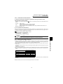
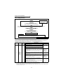
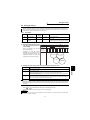
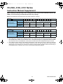
(2) Setting the number of encoder pulses and encoder rotation direction
Set the following parameters according to the encoder specification.
Parameter
Name
Factory Setting
Setting Range
Remarks
851
Number of encoder pulses
2048
0 to 4096
852
Encoder rotation direction
1
0, 1
These parameters are extended
function parameters. Set "1" in
Pr.160 "extended function selection"
z The rotation direction of the encoder is displayed on the operation status indication (FWD,REV) of the control
panel.
0
Rotation direction of the encoder
CW
A
Encoder
2
Forward rotation is clockwise rotation
when viewed from A.
1
(factory setting)
A
CCW
Encoder
Forward rotation is counterclockwise rotation
when viewed from A.
REMARKS
• The number of encoder pulses should be between 1000 and 4096.
z When using a conventional motor and an encoder cable (FR-VCBL/FR-JCBL), refer to the
Instruction Manual (detailed).
13
INSTALLATION AND WIRING
Pr. 852 Setting
Connection diagram, encoder cable,
PU connector
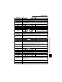
2.2.5
Control circuit terminal specifications
(1) Specification of control circuit terminal
Type Terminal
Symbol
STF
Forward rotation start
STR
Reverse rotation start
OH
Digital input
terminals 1 to 4
Thermal relay protector
input
RES
Reset
SD
Contact input common
(sink)
PC
24VDC power supply
and external transistor
common, contact input
common (source)
10E
Speed setting power
supply
2
Speed setting
Input signals
Contact input
DI1 to DI4
3
1
5
PA
PAR
PB
Encoder signal
Terminal Name
PBR
PZ
PZR
PG
SD
Description
Turn on the STF signal to start forward
rotation and turn it off to stop.
Turn on the STR signal to start reverse
When the STF and STR signals are
rotation and turn it off to stop.
turned on simultaneously, the stop
The function of the terminals changes
command is given.
according to the input terminal function
selection (Pr. 187) setting.
Refer to page 65 for details.
The terminal functions vary with the input terminal function selection (Pr. 180 to Pr.
183) settings. Refer to page 65 for details.
Temperature sensor terminal input for motor overheat protection.
OHT error occurs when terminals OH and SD are open.
Used to reset alarm output provided when protective circuit is activated. By setting
Pr. 75 "reset selection", reset input possible or reset input possible only during
protective circuit operation can be selected. Turn on the RES signal for more than
0.1s, then turn it off.
Common to the contact input. Common output terminal for 24VDC 0.1A power
supply (PC terminal).
Isolated from terminals 5 and SE.
When connecting a transistor output (open collector output), such as a
programmable controller, connect the external power supply common for transistor
output to this terminal to prevent a malfunction caused by a sneak current.
PC-SD can be used as a 24VDC, 0.1A power supply. Note that this connection does
not prevent undesirable currents.
When source logic has been selected, this terminal serves as a contact input common.
10VDC, permissible load current 10mA
By entering 0 to 10VDC, the maximum output speed is reached at 10V and I/O are
Speed setting (voltage) proportional. Acts as a speed command terminal for speed control or as a speed
limit for torque control. Input resistance 10kΩ, maximum permissible voltage 20V.
Acts as a torque setting signal for torque control or a torque limit signal for speed
control and position control.
Torque setting terminal
Acts as an input terminal when torque bias function by external analog is selected.
0 to ±10VDC input, input resistance 10kΩ, maximum permissible voltage ±20VDC
Since this is a multi-function selection terminal, its function varies with the Pr. 868
"terminal 1 function assignment" setting. The function of this terminal is factory-set to
Multi-function setting
adding auxiliary of speed setting terminal of terminal 2.
terminal
Refer to Pr. 868 "terminal 1 function assignment" in the Instruction Manual (detailed).
0 to ±10VDC input, input resistance 10kΩ, maximum permissible voltage ±20V
Speed setting signal (terminal 2, 1 or 3) common terminal.
Speed setting common
Isolated from terminals SD and SE. Do not earth (ground).
A-phase signal input
terminal
A-phase inverted signal
input terminal
B-phase signal input
A-, B- and Z-phase signals are input from the encoder.
terminal
The jumper connector is factory-set to complimentary. Thus, the encoder need not
B-phase inverted signal
be connected to PAR, PBR, and PZR.
input terminal
Z-phase signal input
terminal
Z-phase inverted signal
input terminal
Power supply for encoder. You can switch the power supply between 5 (5.5), 12 and
Encoder power supply
24VDC.
terminal
You can also switch to external power supply.
(Positive side)
The jumper connector is factory-set to 12VDC. (Refer to page 12.)
Common terminal for the encoder power supply.
Power supply earth
Isolated from terminals 5 and SE.
(ground) terminal
Do not earth (ground).
14
Connection diagram, encoder cable,
PU connector
Open collector
RS-485
Communication
Analog
Output signals
Contact
Type Terminal
Symbol
Terminal Name
Description
1 changeover contact output indicates that the inverter protective function activated
and the output stopped.
230VAC 0.3A, 30VDC 0.3A. Alarm: discontinuity across B-C (continuity across A-C),
Normal: continuity across B-C (discontinuity across A-C).
The function of the terminals changes according to the output terminal function
selection (Pr. 195) setting.
Refer to page 65 for details.
A, B, C
Alarm output
DO1 to
DO3
Permissible load 24VDC 0.1A
Digital output terminals
The terminal functions vary with the output terminal function selection (Pr. 190 to Pr.
1 to 3
192) settings. Refer to page 65 for details.
SE
Open collector output
common
DA1
Analog signal output
DA2
Analog signal output
5
Analog signal output
common
–
PU connector
Common terminal for terminals DO1, DO2 and DO3. Isolated from terminals SD and
5.
Factory setting of output item:
One selected from the monitoring items,
Speed
monitoring, output signal 0 to
such as the speed, is output.*
±10VDC, permissible load current 1mA
The output signal is proportional to the
Factory setting of output item:
magnitude of the corresponding monitoring
Speed monitoring, output signal 0 to
item.
10VDC, permissible load current 1mA
Common terminal for DA1 and DA2.
Isolated from terminals SD and SE.
Do not earth (ground).
With the PU connector, communication can be made through RS-485.
• Conforming standard : EIA-485 (RS-485)
• Transmission format : Multidrop link
• Communication speed : Maximum 19200bps
• Overall length
: 500m
2
REMARKS
For the input terminal function switchover timing, refer to page 45.
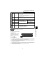
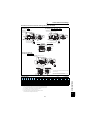
(2) Control circuit terminal layout
Terminal screw size : M3.5
Tightening torque : 1.2N·m
When connecting three or more control cables
to the terminal 5, connect the accessory
terminal 5 dedicated L-shaped jumper to the
terminal 5.
In this case no cable should be connected to
the screw in the
part.
A
B
10E
5
DO1 DO2 DI4
DA1 DO3
2
3
5
C
1
DA2
SE
DI3
PZ
DI2
DI1 STR STF
PZR PG RES PC
PA PAR PB PBR SD
OH
SD
Jumper
(3) Wiring instructions
1)
2)
3)
4)
5)
Terminals 5, SD and SE are common to the I/O signals and isolated from each other. Do not earth (ground)
these terminals. Avoid connecting the terminal SD and 5 and the terminal SE and 5.
Use shielded or twisted cables for connection to the control circuit terminals and run them away from the main
and power circuits (including the 200V relay sequence circuit).
Since the control circuit input signals are micro currents, use two or more parallel micro signal contacts or a
twin contact to prevent a contact fault.
It is recommended to use the cables of 0.75mm2 gauge for connection to the control circuit terminals. If the
cable gauge used is 1.25mm2 or more, the front cover may be lifted when there are many cables running or the
cables are run improperly, resulting in an control panel or parameter unit contact fault.
The maximum wiring length should be 30m.
15
INSTALLATION AND WIRING
* Not output during inverter reset.
Connection diagram, encoder cable,
PU connector
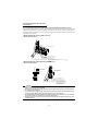
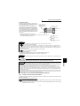
(4) Connecting the control circuit to a power supply separately from the main circuit
If the magnetic contactor (MC) in the inverter power supply is opened when the protective circuit is operated, the
inverter control circuit power is lost and the alarm output signal cannot be kept on. To keep the alarm signal on
terminals R1 and S1 are available. In this case, connect the power supply terminals R1 and S1 of the control circuit
to the primary side of the MC.
• Model FR-V520-1.5K, 2.2K, FR-V540-1.5K, 2.2K
<Connection procedure>
R
S
T
Terminal block for main circuit
R1
S1
1) Loosen the upper screws
2) Remove the lower screws.
3) Remove the jumpers.
4) Connect the separate power supply cables for control circuit to the
lower terminals (R1, S1). (Note 4)
• Model FR-V520-3.7K to 55K, FR-V540-3.7K to 55K
<Connection procedure>
R1 S1
Power supply terminal
block for control circuit
R
S
Power supply terminal
block for control circuit
T
MC
1) Loosen the upper screws.
2) Remove the lower screws.
3) Pull out and remove the jumper.
4) Connect the separate power supply
cables for control circuit to the
upper terminals (R1, S1). (Note 4)
Main power supply
CAUTION
1. When the main circuit power (R, S, T) is on, do not switch off the control power (terminals R1, S1).
Otherwise the inverter may be damaged.
2. When using a separate power supply, the jumpers across R-R1 and S-S1 must be removed. Otherwise
the inverter may be damaged.
3. For a different power supply system, which takes the power of the control circuit from other than the
primary side of the MC, the voltage should be equal to the main circuit voltage.
4. For the FR-V520-3.7K to 55K, FR-V540-3.7K to 55K, the power supply cables must not be connected
to the lower terminals. If connected, the inverter may be damaged.
5. Supplying power to only the R1 and S1 terminals and entering the start signal will result in an error
indication (E.OC1).
16
Connection diagram, encoder cable,
PU connector
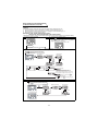
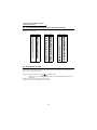
(5) Changing the control logic
The input signals are factory set to sink logic (SINK).
To change the control logic, the jumper connector on the back of the control circuit terminal block must be moved to
the other position.
(The output signals may be used in either the sink or source logic independently of the jumper connector position.)
1) Loosen the two mounting screws in both ends of the control circuit terminal block. (The screws cannot be
removed.) Pull down the terminal block from the back of the control circuit terminals.
2)
Fit the jumper connector from the sink logic (SINK) position on the back surface of the control circuit terminal
block to the source logic (SOURCE) position to change to the source logic.
3)
Using care not to bend the pins of the inverter's control circuit connector, reinstall the control circuit terminal
block and fix it with the mounting screws.
CAUTION
1. Make sure that the control circuit connector is fitted correctly.
2. While power is on, never disconnect the control circuit terminal block.
3. The sink-source logic change-over jumper connector must be fitted in only one of those positions. If
it is fitted in both positions at the same time, the inverter may be damaged.
17
INSTALLATION AND WIRING
2
Connection diagram, encoder cable,
PU connector
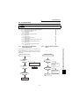
4)
Sink logic type and source logic type
• In sink logic, a signal switches on when a current flows from the corresponding signal input terminal.
Terminal SD is common to the contact input signals. Terminal SE is common to the open collector output
signals.
• In source logic, a signal switches on when a current flows into the corresponding signal input terminal.
Terminal PC is common to the contact input signals. Terminal SE is common to the open collector output
signals.
Current flow concerning the RUN signal
when sink logic is selected
Current flow concerning the RUN signal
when source logic is selected
Sink connector
Sink logic
Source logic
PC
Current
Current
STF
STR
R
STF
R
STR
Source
connector
R
R
SD
DC input (sink type)
<Example : AX40>
Inverter
RUN
1
DC input (source type)
<Example : AX80>
Inverter
R
RUN
1
R
R
R
SE
SE
9
9
24VDC
24VDC
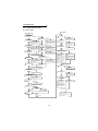
z When using an external power supply for transistor output
• Sink logic type
• Source logic type
Use terminal PC as a common terminal to prevent a
Use terminal SD as a common terminal to prevent a
malfunction caused by undesirable current. (Do not
malfunction caused by undesirable current.
connect terminal SD of the inverter with terminal 0V
of the external power supply. When using terminals
PC-SD as a 24VDC power supply, do not install a
power supply in parallel in the outside of the inverter.
Doing so may cause a malfunction due to
undesirable current.)
AY80 type
transistor
output module
9
STF
2
STR
24VDC
(SD)
1
STF
2
STR
9
PC
9
10
Inverter
PC
10
24VDC
Inverter
AY40 type
transistor
output module 1
SD
24VDC SD
Current flow
Current flow
18
24VDC
(SD)
Connection diagram, encoder cable,
PU connector
2.2.6
Connection to the PU connector
(1) When connecting the control panel or parameter unit using a connection cable
<Recommended connection cable>
• Parameter unit connection cable (FR-CB2
) (option) or the following connector and cable available on the
market
• Connector : RJ45 connector
Example: 5-554720-3 of Tyco Electronics Corporation
• Cable
: Cable conforming to EIA568 (e.g. 10BASE-T cable)
Example: SGLPEV-T 0.5mm x 4P(twisted pair cable, 4 pairs) of Mitsubishi Cable Industries, LTD.
• Maximum wiring length : 20m
(2) For computer link communication
Using the PU connector, you can perform communication operation from a personal computer etc. When the PU
connector is connected with a personal, FA or other computer by a communication cable, a user program can run
and monitor the inverter or read and write to parameters.
Refer to the Instruction Manual (detailed) for details.
Conforming Standard : EIA-485 (RS-485)
Transmission form
: Multidrop link
Communication speed : Maximum 19200bps
Overall length
: 500m
CAUTION
Do not connect the PU connector to the computer's LAN board, FAX modem socket or telephone
connector. The product could be damaged due to differences in electrical specifications.
2.2.7
2
Earthing (Grounding) precautions
z Leakage currents flow in the inverter. To prevent an electric shock, the inverter and motor must be earthed
(grounded). Earthing (Grounding) must conform to the requirements of national and local safety regulations and
electrical codes. (NEC section 250, IEC 536 class 1 and other applicable standards.)
z Use the dedicated earth (ground) terminal to earth (ground) the inverter. (Do not use the screw in the case,
chassis, etc.)
Use a tinned* crimping terminal to connect the earth (ground) cable. Tighten the screw, taking care not to break
its threads.
*Plating should not include zinc.
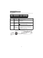
z Use the thickest possible earth (ground) cable. Use the cable whose size is equal to or greater than that indicated
below, and minimize the cable length. The earthing (grounding) point should be as near as possible to the
inverter.
Motor Capacity
2.2kW or less
3.7kW
5.5kW, 7.5kW
11kW, 15kW
18.5kW to 37kW
45kW, 55kW
Earth (Ground) Cable Gauge
200V class
400V class
2 (2.5)
3.5 (4)
5.5 (6)
14 (16)
22 (25)
38 (35)
2 (2.5)
2 (2.5)
3.5 (4)
8 (10)
14 (16)
22 (25)
For use as a product compliant with the Low Voltage Directive, use PVC cable whose size is indicated within
parentheses.
z Earth (Ground) the motor on the inverter side using one wire of the 4-core cable.
19
INSTALLATION AND WIRING
•
•
•
•
Setting the motor
2.3 Setting the motor
This inverter is factory-set to run the dedicated motor (SF-V5RU (1500r/min series) with encoder)
0
10
SF-JR
SF-HRCA
Inverter internal constants
Inverter internal constants
(It is not necessary to reset the inverter if you use the dedicated motor (SF-V5RU (1500r/min series) with encoder)
(only when inverter capacity = motor capacity).)
POINT
The parameter below is extended mode parameter. Set "1" in Pr. 160 "extended function selection".
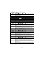
2.3.1
Dedicated motor (SF-V5RU (1500r/min series))
Check that the Pr.71 "applied motor" (extended mode) setting is "30" (SF-V5RU) (factory setting value).
2.3.2
Motor one rank lower than the dedicated motor (SF-V5RU (1500r/min series))
Set the parameter shown below.
Parameter
Name
Factory Setting
Setting Range
80
Motor capacity
Inverter capacity
0.4kW to 55kW
20
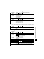
Setting the motor
REMARKS
1
2
3
4
5
6
7
8
9
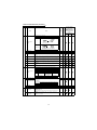
1.
2.
3.
4.
5.
Item
Motor
setting
Offline
tuning
Parameter,
Jumper
Connector,
Terminal
Pr. 71 setting
Dedicated Motor
Mitsubishi
Mitsubishi
SF-JR (with encoder)
SF-V5RU SF-VRSF-HR
(4P)1500r/min 5.5kW to (2, 4, 6P)(with
2.2kW
to
1.5kW
or
series
45kW
encoder)
55kW
less
30
30
Constant-torque Motor
(with encoder)
Mitsubishi
Standard Motor
0
20
3 to 8
Other
Other
Others manufacturer SF-HRCA SF-JRCA
(with
(with
(4P) (with
(with manufacturer
encoder) encoder) encoder) encoder)
3 to 8
Not
Not
Not
Not
Required Required
required * required * required * required *
INV
INV
INV
INV
INV
INV
1 :1
capacity
capacity
capacity
capacity
capacity
capacity
Capacity
Pr. 80 setting
setting
1 rank
Motor
Motor
Motor
Motor
Motor
Motor
lower
capacity
capacity
capacity
capacity
capacity
capacity
Number
of
Pr. 851setting
2048
1000
1024
1024
1024
(*2)
encoder
pulses
Encoder
1
1
1
1
1
(*2)
rotation Pr. 852 setting
direction
Encoder
Power
Encoder
power
12V
5V
5V
5V
5V
(*2)
supply
supply power supply
specification
jumper
specification
connector on
Output
(*2)
Encoder the back of circuit Complimentary Differential Differential Differential Differential
the control
output
Terminating
terminal
type
No
Yes
Yes
Yes
Yes
(*2)
resistance
Electronic
Rated
Rated
Rated
0
0
motor
motor
motor
(*2)
thermal Pr. 9 setting
current
current
current
relay
Across
Connect to Connect to
Thermal
Open
Open
Open
(*2)
OH-SD
the thermal the thermal
protector
input Pr. 876 setting
1
1
0
0
0
(*2)
3 to 8
Required
INV
capacity
Motor
capacity
10
13 to 18
13 to 18
Not
Required Required
required *
INV
INV
INV
capacity
capacity capacity
Motor
Motor
Motor
capacity
capacity capacity
(*2)
1024
1024
(*2)
(*2)
1
1
(*2)
(*2)
5V
5V
(*2)
(*2)
Differential Differential
(*2)
(*2)
Yes
Yes
(*2)
(*2)
Rated
motor
current
Rated
motor
current
(*2)
(*2)
Open
Open
(*2)
(*2)
0
0
(*2)
CAUTION
Set number of motor poles in Pr.81.
Make setting according to the motor used.
The half-tone screened cells are factory set.
Check the power supply specification of encoder and change a jumper connector.
*:Perform offline auto tuning (mode without rotation) for the wiring length to be reflected on the
control when exercising magnetic flux observer and the wiring length is long (30m or longer as
reference).
<When using other manufacturers’ motors>
Offline auto tuning (rotation mode) is necessary. Perform offline auto tuning with the motor alone before connecting
a load. If higher torque accuracy is required, perform online auto tuning next.
Offline auto tuning
The inverter measures necessary motor circuit constant and stores it to improve low speed
torque.
Online auto tuning
High torque accuracy corresponding to the motor temperature variation is available.
21
2
INSTALLATION AND WIRING
No.
Description
When using a conventional motor (SF-VR, SF-JR) or other motors, refer to the
Instruction Manual (detailed).
<At-a-glance guide to setting the motor>
Precautions for use of the vector inverter
2.4 Precautions for use of the vector inverter
The FR-V500 series is a highly reliable product, but incorrect peripheral circuit making or operation/handling
method may shorten the product life or damage the product.
Before starting operation, always recheck the following items.
(1) Use insulation-sleeved crimping terminals for the power supply and motor cables.
(2) The inverter will be damaged if power is applied to the inverter output terminals (U, V, W).
(3) After wiring, wire offcuts must not be left in the inverter.
Wire offcuts can cause an alarm, fault or malfunction. Always keep the inverter clean.
When drilling mounting holes in an enclosure etc., take care not to allow chips and other foreign matter to enter
the inverter.
(4) Wire the cables of the recommended size to make a voltage drop 2% or less.
If the wiring distance is long between the inverter and motor, a main circuit cable voltage drop will cause the
motor torque to decrease especially at the output of a high frequency.
Refer to page 11 for the recommended wire sizes.
(5) The overall wiring length should be 100m maximum.
Especially for long distance wiring, the fast response current limit function may be reduced or the equipment
connected to the secondary side may malfunction or become faulty under the influence of a charging current
due to the stray capacity of the wiring. Therefore, note the overall wiring length.
(6) Electromagnetic wave interference
The input/output (main circuit) of the inverter includes high frequency components, which may interfere with the
communication devices (such as AM radios) used near the inverter. In this case, install the optional FR-BIF radio
noise filter (for use on the input side only) or FR-BSF01 or FR-BLF line noise filter to minimize interference.
(7) Do not install a power factor correction capacitor, surge suppressor or radio noise filter (FR-BIF option) on the
output side of the inverter.
This will cause the inverter to trip or the capacitor and surge suppressor to be damaged. If any of the above devices is
installed, immediately remove it. (When the FR-BIF radio noise filter is connected, switching power off during motor
operation may result in E. UVT. In this case, connect the radio noise filter in the primary side of the magnetic contactor.)
(8) Before starting wiring or other work after the inverter is operated, wait for at least 10 minutes after the power
supply has been switched off, and check that there are no residual voltage using a tester or the like. The
capacitor is charged with high voltage for some time after power off and it is dangerous.
(9) A short circuit or earth (ground) fault in the inverter output side may damage the inverter modules.
• Fully check the insulation resistance of the circuit prior to inverter operation since repeated short circuits
caused by peripheral circuit inadequacy or an earth (ground) fault caused by wiring inadequacy or reduced
motor insulation resistance may damage the inverter modules.
• Fully check the to-earth (ground) insulation and inter-phase insulation of the inverter secondary side before power on.
Especially for an old motor or use in hostile atmosphere, securely check the motor insulation resistance etc.
(10) Do not use the inverter power supply side magnetic contactor to start/stop the inverter.
Always use the start signal (turn on/off terminals STF, STR-SD) to start/stop the inverter. (Refer to page 7.)
(11) Across the P and PR terminals, connect only an external regenerative brake discharge resistor.
Do not connect a mechanical brake.
(12) Do not apply a voltage higher than the permissible voltage to the inverter I/O signal circuits.
Contact to the inverter I/O signal circuits or opposite polarity may damage the I/O devices. Especially check the
wiring to prevent the speed setting potentiometer from being connected incorrectly to short terminals 10E-5.
(13) Use of single-phase power supply
Do not use single-phase power input.
(14) Precautions for use of any motor other than the vector control dedicated motor (SF-V5RU, SF-VR) and
standard motor with encoder (SF-JR)
a)Vector control cannot be exercised without encoder.
b)Connect the encoder to the backlash-free motor shaft.
(15) Since the rated voltage differs from the commercial power supply voltage, the Mitsubishi dedicated motor
cannot perform bypass operation.
SF-V5RU
SF-V5RUH
3.7kW or less
5.5kW or more
3.7kW or less
5.5kW or more
22
170V
160V
340V
320V
Checks prior to test run
3
RUN AND OPERATION
3.1 Checks prior to test run
Installation check
Check that the inverter is installed correctly in a correct place. (Refer to page 6.)
Wiring check
Check that wiring is correct. (Refer to page 7.)
3.2 Basic operation (Speed setting, run, speed meter adjustment)
3.2.1
Setting the speed and running the motor
(1) Choosing PU operation mode (operation from the control panel (FR-DU04-1)) and
running at 150r/min
Display
Operation
Operation mode check
The external operation mode (EXT) is selected when
switching power on with factory setting.
Make sure that the run command indication "PU" is lit.
If it does not appear, press MODE to choose the operation
mode, and press
to choose the PU operation mode.
When the desired result is not obtained, set the PU operation
mode in Pr.79.
ON
FR-DU04-1
CONTROL PANEL
Hz/r
A
V
MON
FR-DU04-1
2. Running speed setting
EXT
PU
REV
FWD
CONTROL PANEL
(or)
Hz/r
A
V
Set the running speed to 150r/min.
First, press MODE to choose the speed setting mode.
Then, press
to change the setting, and press
SET to write the value.
MON
FR-DU04-1
3. Start
FWD
Press
or
.
The motor starts. The mode is automatically switched
to the monitoring mode and the output speed is displayed.
(or)
EXT
PU
REV
FWD
CONTROL PANEL
Hz/r
A
V
REV
REV
FWD
MON
FR-DU04-1
4. Stop
STOP
Press
.
RESET
The motor is decelerated to a stop.
EXT
PU
REV
FWD
CONTROL PANEL
Hz/r
A
V
STOP
RESET
MON
EXT
PU
REV
FWD
REMARKS
• The running speed can be changed by changing the preset speed during operation following the steps 2 and 3 above.
• For monitor display changes by
MODE
, refer to page 28.
• To select the PU operation mode in Pr.79 "operation mode selection", set "1" in the parameter. Refer to page 56 for details.
23
3
RUN AND OPERATION
1. Power on
Basic operation (Speed setting, run,
speed meter adjustment)
z PU jog operation
Hold down FWD or REV to perform operation, and release it to stop.
1)Set Pr. 15 "jog speed setting" and Pr. 16 "jog acceleration/deceleration time".
2)Set PU jog operation. (Press
operation.)
MODE
to select the operation mode and press
to switch to PU jog
3)Hold down the FWD or REV key to perform operation.
(If the motor remains stopped, check Pr. 13 "starting speed". The motor will not start if its setting is lower than
the starting speed.)
REMARKS
• If the motor does not rotate ⇒ ·Checking the encoder jumper connector (Refer to page 12.)
·Checking the phase sequence of the encoder cable (Refer to page 12.)
·For other cases, refer to Troubleshooting on page 85.
• When you want to set the speed to higher than 1500r/min, set Pr. 1 "maximum speed". (Refer to page 55.)
(2) Choosing external operation mode (operation
potentiometer and external start signals)
z Running at 1500 r/min
using
external
speed
setting
•Run command: start signals connected outside
•Speed setting: speed setting potentiometer connected outside
Operation
Display
1. Power on
Operation mode check
The external operation (EXT) is selected when switching
ON
power on with factory setting. Make sure that the run
command indication "EXT" is lit.
If it does not appear, press MODE to choose the operation mode,
and press
to choose the external (EXT) operation mode.
When the desired result is not obtained, set the external
operation mode in Pr.79.
2. Start
Turn on the start switch (STF or STR).
The operation status indication FWD or REV flickers.
Forward
rotation Reverse
rotation
Hz/r
A
V
MON
FR-DU04-1
FR-DU04-1
Constant speed
Slowly turn the potentiometer (speed setting potentiometer)
connected to across terminals 2-5 full clockwise.
The speed shown on the display increases gradually to
1500r/min.
MON
FR-DU04-1
is valid.
PU
REV
FWD
CONTROL PANEL
EXT
PU
REV
FWD
CONTROL PANEL
Hz/r
A
V
4. Deceleration
CAUTION
When Pr. 75 "PU stop selection" = "14 to 17",
EXT
Hz/r
A
V
MON
3. Acceleration
Slowly turn the potentiometer (speed setting potentiometer)
connected to across terminals 2-5 full counterclockwise.
The speed shown on the display decreases gradually to 0r/min.
The motor stops running.
5. Stop
Turn off the start switch (STF or STR).
CONTROL PANEL
ON
CAUTION
The motor does not start if both the forward and reverse
rotation switches are turned on. If both switches are
turned on during operation, the motor decelerates to a stop.
STOP
RESET
FR-DU04-1
EXT
PU
REV
FWD
CONTROL PANEL
Hz/r
A
V
MON
Forward
rotation Reverse
rotation
EXT
PU
REV
FWD
Stop
OFF
REMARKS
• The running speed of the external potentiometer can be adjusted in Pr. 902 and Pr. 903 (bias and gain of the speed setting
terminal). (Refer to page 51.)
• For monitor display changes by MODE , refer to page 28.
• To select the external operation mode in Pr. 79 "operation mode selection", set "2" in the parameter. Refer to page 56 for
details.
24
Basic operation (Speed setting, run,
speed meter adjustment)
z External jog operation
Keep the start switch (STF or STR) on to perform operation, and turn it off to stop.
1)Set Pr. 15 "jog speed setting" and Pr. 16 "jog acceleration/deceleration time".
2)Select the external operation mode.
3)Switch on the jog signal. Keep the start switch (STF or STR) on to perform operation.
Assign the terminal used for the jog signal in any of Pr. 180 to Pr. 183 and Pr. 187
(input terminal function selection). (Refer to page 65.)
(3) Choosing external/PU combined operation mode 1 (operation using the external start
signal and control panel)
z When setting the start signals from outside inverter (e.g. switches or relays) and the
running speed from the control panel (Pr. 79 = 3)
•Run command: start signal connected outside
•Speed setting:
of PU or multi-speed command (multi-speed command has priority)
For multi-speed command, refer to Pr.4 to Pr.6 on page 54.
Operation
Display
1. Power on
ON
Switch power on.
2. Operation mode selection
Set "3" in Pr. 79 "operation mode selection".
(Refer to page 56 for details of Pr.79.)
The combined operation mode is selected and the operation
status indication "EXT" and "PU" are lit.
Flicker
3. Start
FR-DU04-1
Hz/r
A
V
MON
FR-DU04-1
4. Running speed setting
Using
, of PU, set the running speed to 150r/min
EXT
PU
REV
FWD
CONTROL PANEL
Hz/r
A
V
SET
MON
and press SET .
The run command indication FWD or REV is lit.
5. Stop
FR-DU04-1
Turn off the start switch (STF or STR).
The motor decelerates to stop.
The operation status indication "FWD" or "REV" is lit.
CONTROL PANEL
Reverse
rotation
Forward
rotation Reverse
rotation
EXT
PU
REV
FWD
CONTROL PANEL
Hz/r
A
V
MON
EXT
PU
REV
FWD
OFF
CAUTION
When Pr. 75 "PU stop selection" = "14 to 17",
STOP
RESET
is valid.
REMARKS
When setting the start signal from the PU and speed setting signal from outside inverter, set "4" (combined operation mode 2)
in Pr.79 "operation mode selection".
25
3
RUN AND OPERATION
Turn on the start switch (STF or STR).
The operation status indication "FWD" or "REV" is lit.
Forward
REMARKS
rotation
• The motor does not start if both the forward and
ON
reverse rotation switches are turned on. If both
switches are turned on during operation, the motor
decelerates to a stop.
• Set the speed in the speed setting mode (Refer to page 28.).
Basic operation (Speed setting, run,
speed meter adjustment)
3.2.2
Adjustment (calibration) of speed meter (meter)
Changing example At the preset speed of 1500r/min, make adjustment so that the meter (analog meter)
deflects to full-scale. Calibrate the DA1 terminal (±10V).(in PU operation mode)
POINT
• Pr. 900 "DA1 terminal calibration" can be read by setting "1" (extended function parameter enable) in
Pr. 160 "extended function selection".
• Set Pr. 900 "DA1 terminal calibration".
• Set any of "1 to 3, 5 to 12, 17, 18, 21, 32 to 34 and 36" in Pr. 54 "DA1 terminal function selection" to
output a signal to the terminal DA1. (Refer to page 60)
Display
Operation
1. Press FWD to operate the inverter. (It is not necessary to
connect a motor.)
2. Press
MODE
FR-DU04-1
to select the parameter setting mode.
Hz¤r
A
V
MON
3. Display the present running speed by pressing
read Pr. 900.
CONTROL PANEL
MODE
SET
to
or
to adjust the meter pointer to
4. Press
a predetermined position. (Depending on the setting,
it may take some time until the pointer moves.)
EXT
PU
REV
FWD
SET
(Analog voltage meter)
REMARKS
1. Pressing REV to start reverse rotation operation will move the
meter pointer reversely (in the negative direction).
2. The terminal DA1 output will also keep displaying the monitor
when the inverter stops due to an alarm.
5. Press SET for about 1.5s.
This completes the setting.
Flicker ...
Parameter setting complete!!
6. Press
STOP
RESET
to stop the inverter.
CAUTION
1. When the speed meter is connected across terminals DA1-5 to monitor the speed, the output of
terminal DA1 is saturated if the maximum output speed reaches or exceeds 1500r/min, with the
factory setting unchanged. Hence, the setting of Pr. 55 "speed monitoring reference" must be
changed to the maximum output speed. (Refer to page 60.)
2. Terminal DA2 can be adjusted in Pr. 901
3. For operation from the parameter unit (FR-PU04V), refer to the instruction manual of the FR-PU04V.
REMARKS
• For monitor display changes by
MODE
, refer to page 28.
• Calibration can be made also during external operation.
26
Names and functions of the control panel
3.3 Names and functions of the control panel
With the control panel (FR-DU04-1), you can perform operation, set the speed, monitor the run command display,
set parameters, display an error, and copy parameters.
CONTROL PANEL
Hz/r
A
V
Display
LED 4 digits
MON
Mode key
EXT
PU
REV
FWD
MODE
SET
Setting key
REV
Unit indication
Hz/r (motor speed)
A (current)
V (voltage)
Operation status indication
FWD
STOP
RESET
Forward rotation key
Reverse rotation key
Stop/reset key
Up/down keys
REMARKS
The ON of the LED is indicated by{, and OFF byz.
z Key indication
Key
Description
MODE
Select the operation mode or setting mode.
SET
Determine the speed or parameter setting.
• Used to increase or decrease the running speed consecutively. Hold down this key to change the
speed.
• Press this key in the setting mode to change the parameter setting consecutively.
Forward rotation command key.
REV
Reverse rotation command key.
3
• Used to stop operation.
• Used to reset the inverter when the protective function (major fault) is activated to stop the output.
STOP
RESET
z Unit indication, operation status indication
Indication
Hz/r
A
V
MON
PU
EXT
FWD
REV
Description
Lit to indicate the output speed.
Lit to indicate the current.
Lit to indicate the voltage.
Lit in the monitor display mode.
Lit in the PU operation mode.
Lit in the external operation mode.
Flickers during forward rotation.
Flickers during reverse rotation.
27
RUN AND OPERATION
FWD
Names and functions of the control panel
3.3.1
Monitor display changed by pressing
Speed setting mode (Caution)
Monitoring mode
FR-DU04-1
FR-DU04-1
CONTROL PANEL
Hz/r
A
V
MON
EXT
PU
REV
FWD
Hz/r
A
V
MODE
MON
EXT
PU
REV
FWD
Operation mode
Parameter setting mode
FR-DU04-1
CONTROL PANEL
MODE
Hz/r
A
V
MODE
MON
FR-DU04-1
CONTROL PANEL
EXT
PU
REV
FWD
Hz/r
A
V
MODE
MON
Help mode
FR-DU04-1
CONTROL PANEL
EXT
PU
REV
FWD
CONTROL PANEL
Hz/r
A
V
MODE
MON
EXT
PU
REV
FWD
MODE
CAUTION
The speed setting mode appears only when the operation mode is the PU operation mode.
3.3.2
Monitoring
• Run command indications in the monitoring mode
EXT is lit to indicate external operation.
PU is lit to indicate PU operation.
Both EXT and PU are lit to indicate PU/external combined operation.
• The monitor display can also be changed during operation.
Speed monitor
FR-DU04-1
Current monitor
Hz/r
A
V
MON
FR-DU04-1
CONTROL PANEL
EXT
PU
REV
FWD
Voltage monitor
Hz/r
A
V
SET
MON
FR-DU04-1
CONTROL PANEL
EXT
PU
REV
FWD
CONTROL PANEL
Hz/r
A
V
SET
MON
SET
SET
*1
*1
Alarm
absent
EXT
PU
REV
FWD
Alarm monitor
FR-DU04-1
CONTROL PANEL
Hz/r
A
V
SET
MON
EXT
PU
REV
FWD
SET
Alarm
present
*1
SET
SET
MODE
*2
To 3.3.3 Speed setting (Caution 3)
CAUTION
1. Hold down
SET
marked *1 for more than 1.5s to change the current monitor to the power-on monitor.
2. Hold down SET marked *2 for more than 1.5s to display the last four errors including the latest one.
3. In the external operation mode, it shifts to the parameter setting mode.
3.3.3
Speed setting
• Used to set the running speed in the PU operation mode.
To speed monitor
MODE
Speed setting mode
FR-DU04-1
CONTROL PANEL
Set speed change
FR-DU04-1
Hz/r
A
V
MON
MODE
EXT
PU
REV
FWD
Hz/r
A
V
MON
Press
EXT
PU
REV
FWD
/
Flicker
Set speed write
FR-DU04-1
CONTROL PANEL
CONTROL PANEL
MON
to change the set speed.
To 3.3.4 Parameter setting method
28
FR-DU04-1
CONTROL PANEL
Hz/r
A
V
SET
EXT
PU
REV
FWD
Hz/r
A
V
MON
EXT
PU
REV
FWD
Names and functions of the control panel
3.3.4
Parameter setting method (Example: Method to enable extended function
parameters)
• A parameter value may either be set by updating its parameter number or setting the value digit-by-digit using
.
• To write the setting, change it and press SET for 1.5s.
Example: To change the Pr. 160 "extended function selection" setting from "0" (extended function parameter
invalid) to "1" (extended function parameter valid) (Refer to page 56 for details of Pr. 160.)
Press
MODE
to choose the "parameter setting mode".
Parameter setting mode
FR-DU04 -1
Hz/r
A
V
MON
Most significant
digit flickers
CONTROL PANEL
EXT
PU
REV
FWD
Least significant
digit flickers
Middle digit
flickers
SET
1 time
6 times
or
or
9 times
MODE
4 times
To 3.3.5 Operation mode
SET
SET
0 to 9
Current setting
0 to 9
Setting change
SET
Press for
1.5s
SET
Setting write
appears
1) When [FWD] or [REV] indication is lit,
MON
EXT
PU
STOP
stop operation by pressing
or
RESET
REV
FWD
turning off the forward rotation (STF) or
reverse rotation (STR) signal connected
to the control terminal.
2) You cannot set any value outside the parameter setting range.
Write a value within the setting range.
Flicker
"1" (extended function parameter valid) has been set in Pr. 160.
If the value and parameter number
do not flicker and
appears instead, you did not press
for 1.5s when
writing the value.
SET
Press
3.3.5
once, press
SET
, and restart the setting from the beginning.
Operation mode
External operation
FR-DU04-1
CONTROL PANEL
PU operation
FR-DU04-1
PU jog operation
CONTROL PANEL
Hz/r
A
V
MON
EXT
PU
REV
FWD
FR-DU04-1
CONTROL PANEL
Hz/r
A
V
MON
EXT
PU
REV
FWD
MODE
Hz/r
A
V
MON
EXT
PU
REV
FWD
MODE
MODE
To 3.3.6 Help mode
REMARKS
If one operation mode cannot be switched to another, check the following items.
• External input signals ..... Make sure that the STF and STR signals are off.
• Parameter setting ........... Check the Pr. 79 setting.
When the Pr. 79 "operation mode selection" setting is "0" (factory setting), the inverter is placed
in the external operation mode at input power-on. At this time, press
on the control panel
twice and press
(press
when the parameter unit (FR-PU04V) is used) to switch to the PU
operation mode. For the other values (1 to 8), the operation mode is limited accordingly.
MODE
PU
29
3
RUN AND OPERATION
If
Names and functions of the control panel
3.3.6
Help mode
Alarm history
FR-DU04-1
Alarm history
clear
CONTROL PANEL
Parameter
clear
All clear
Software version
read
Hz/r
A
V
MON
EXT
PU
REV
FWD
MODE
To 3.3.2 Monitoring
(1) Alarm history
Four past alarms can be displayed with
("." is appended to the latest alarm.)
When no alarm exists,
.
is displayed.
Latest alarm
FR-DU04-1
H/zr
A
V
MON
FR-DU04-1
CONTROL PANEL
EXT
PU
REV
FWD
Second past
FR-DU04-1
CONTROL PANEL
SET
Third past
Hz/r
A
V
MON
EXT
PU
REV
FWD
FR-DU04-1
CONTROL PANEL
Fourth past
CONTROL PANEL
Hz/r
A
V
MON
EXT
PU
REV
FWD
FR-DU04-1
CONTROL PANEL
Hz/r
A
V
MON
EXT
PU
REV
FWD
Hz/r
A
V
MON
EXT
PU
REV
FWD
SET
At alarm
Output speed
FR-DU04-1
Current
Voltage
FR-DU04-1
CONTROL PANEL
Hz/r
A
V
MON
EXT
PU
REV
FWD
Energization time
FR-DU04-1
CONTROL PANEL
CONTROL PANEL
Hz/r
A
V
MON
EXT
PU
REV
FWD
FR-DU04-1
MON
EXT
PU
REV
FWD
Hz/r
A
V
MON
(2) Alarm history clear
Clears all alarm history.
Flicker
FR-DU04-1
Hz/r
A
V
MON
FR-DU04-1
CONTROL PANEL
EXT
PU
REV
FWD
CONTROL PANEL
FR-DU04-1
MON
SET
EXT
PU
REV
FWD
Hz/r
A
V
MON
Cancel
30
FR-DU04-1
CONTROL PANEL
Hz/r
A
V
SET
CONTROL PANEL
Hz/r
A
V
EXT
PU
REV
FWD
CONTROL PANEL
Hz/r
A
V
SET
MON
EXT
PU
REV
FWD
EXT
PU
REV
FWD
Names and functions of the control panel
(3) Parameter clear
Initializes the parameter values to the factory settings. The calibration values are not initialized.
(Parameter values are not cleared by setting "1" in Pr. 77 "parameter write disable selection".)
Flicker
FR-DU04-1
Hz/r
A
V
MON
FR-DU04-1
CONTROL PANEL
EXT
PU
REV
FWD
FR-DU04-1
CONTROL PANEL
MON
SET
EXT
PU
REV
FWD
Hz/r
A
V
MON
FR-DU04-1
CONTROL PANEL
Hz/r
A
V
SET
EXT
PU
REV
FWD
CONTROL PANEL
Hz/r
A
V
SET
MON
EXT
PU
REV
FWD
Cancel
REMARKS
Pr. 75, Pr. 82, Pr. 90 to Pr. 94, Pr. 96, Pr. 145, Pr. 171, Pr. 180 to Pr. 183, Pr. 187, Pr. 190 to Pr. 192, Pr. 195,
Pr.496, Pr.497, Pr.819, Pr. 849, Pr.868, Pr.880, Pr.890 to Pr.892, Pr. 900 to Pr. 905, Pr. 917 to Pr. 920, and Pr. 991 are not
initialized.
(4) All clear
Initializes the parameter values and calibration values to the factory settings.
(Parameter values are not cleared by setting "1" in Pr. 77 "parameter write disable selection".)
Flicker
FR-DU04-1
Hz/r
A
V
MON
FR-DU04-1
CONTROL PANEL
EXT
PU
REV
FWD
FR-DU04-1
CONTROL PANEL
MON
SET
EXT
PU
REV
FWD
Hz/r
A
V
MON
FR-DU04-1
CONTROL PANEL
Hz/r
A
V
SET
EXT
PU
REV
FWD
CONTROL PANEL
Hz/r
A
V
SET
MON
EXT
PU
REV
FWD
Cancel
3
REMARKS
RUN AND OPERATION
Pr. 75, Pr. 145, Pr. 171, Pr. 496, Pr. 497 and Pr. 891 are not initialized.
31
Names and functions of the control panel
3.3.7
Copy mode
By using the control panel (FR-DU04-1), the parameter values can be copied to another inverter (only the FR-V500
series).
1) Operating procedure
After reading the parameter values from the copy source inverter, connect the control panel to the copy
destination inverter, and write the parameter values.
After writing the parameter values to the copy destination inverter, always reset the inverter, e.g. switch power
off once, before starting operation.
Parameter setting mode
FR-DU04-1
FR-DU04-1
CONTROL PANEL
CONTROL PANEL
Hz/r
A
V
MON
FR-DU04-1
EXT
PU
REV
FWD
MON
FR-DU04-1
CONTROL PANEL
Hz/r
A
V
MON
Hz/r
A
V
EXT
PU
REV
FWD
EXT
PU
REV
FWD
FR-DU04-1
CONTROL PANEL
CONTROL PANEL
Hz/r
A
V
SET
MON
Press for
1.5s
EXT
PU
REV
FWD
FR-DU04-1
MON
(Caution 1)
SET
Press for
1.5s
PU
REV
FWD
EXT
PU
REV
FWD
CONTROL PANEL
Hz/r
A
V
MON
(Caution 1)
SET
FR-DU04-1
CONTROL PANEL
EXT
CONTROL PANEL
Hz/r
A
V
MON
FR-DU04-1
Hz/r
A
V
Press for
1.5s
EXT
PU
REV
FWD
(Caution 1)
SET
FR-DU04-1
CONTROL PANEL
Hz/r
A
V
MON
Parameter read
EXT
PU
REV
FWD
Parameter write
Connect to copy destination inverter.
Hz/r
A
V
MON
EXT
PU
REV
FWD
Parameter verify
After writing the parameter values,
always reset the inverter prior to
the start of operation.
CAUTION
1. While the copy function is being activated, the monitor display flickers. The display returns to the litup state on completion of the copy function.
2. If a read error occurs during parameter read, "read error (E.rE1)" is displayed.
3. If a write error occurs during parameter write, "write error (E.rE2)" is displayed.
4. If a data discrepancy occurs during parameter verify, the corresponding parameter number and
"verify error (E.rE3)" are displayed alternately. If the directly preset speed or jog speed setting differs,
"verify error (E.rE3)" flickers. Press SET to ignore this display and continue verify.
5. When the copy destination inverter is not the FR-V500, "model error (E.rE4)" is displayed.
Reference:
It is recommended to perform parameter read after completion of parameter setting. (When
performing auto tuning, it is recommended to perform read after completion of auto tuning.) When the
inverter has been changed, performing parameter write from the control panel fitted to a new inverter
completes parameter setup.
32
Speed control operation
4
CONTROL
This inverter can control a motor under speed, torque or position control. (As required, set "1" (extended
function parameters valid) in Pr. 160 "extended function selection".)
Refer to page 29 for the setting method of Pr. 160 "extended function selection" and to page 56 for details.
(Since the factory setting of Pr. 77 is "0", perform parameter write in the PU mode or during a stop.)
4.1 Speed control operation
4.1.1
Speed control
Speed control is exercised to match the speed command and actual motor speed.
Speed response ........ Maximum 800rad/s by internal processing and maximum 300rad/s (without adaptive
magnetic flux observer) by analog input signal are available (motor speed response to the
speed command).
4.1.2
Operation transition
z Turning on the start signal increases the
speed up to the preset speed according to the
acceleration time.
z Turning off the start signal decreases the
speed according to the deceleration time.
When the speed has decreased down to the
DC brake operation speed, operation
changes to 0 speed control or servo lock.
(Refer to Pr. 802 "pre-excitation selection " on
page 70.)
Speed command
Acceleration time
in Pr. 7
Deceleration time in Pr. 8
Pr. 13 "starting speed"
Speed
Start signal
RUN signal
Pr. 10 "DC injection
brake operation
speed"
REMARKS
• When the RT signal is off, Pr. 7 and Pr. 8 are acceleration time and deceleration time.
• When the RT signal is on, Pr. 44 and Pr. 45 (second acceleration/deceleration time) are acceleration/
deceleration time.
• Pr. 44 and Pr. 45 are valid when the RT signal is on, and Pr. 110 and Pr. 111 (third acceleration/deceleration
time) are valid when the X9 signal is on. When both the RT and X9 are on, Pr. 110 and Pr. 111 are valid.
Setting procedure
Perform secure wiring. (Refer to page 7.)
Set the encoder. (Refer to page 12.)
4
It is not necessary to set the
encoder and motor when
using the dedicated motor
(SF-V5RU).
Set the motor to be used. (Refer to page 20.)
Refer to page 20 if the motor is one rank lower.
Set any of "0 (speed control), 2 (speed-torque switchover), 4 (speed-position switchover)" in Pr. 800 "control method
selection" to make speed control valid. The parameter is factory-set to 0 (speed control). (Refer to page 57.)
Set the run command. (Refer to page 34.)
Test run (Refer to page 23.)
As required
1) Gain adjustment (Refer to page 47.)
<Perform easy gain tuning.>
2) Set the torque limit value (Refer to page 34.)
Set the speed limit during torque control.
33
CONTROL
4.1.3
Speed control operation
4.1.4
Run command setting
(1) Forward and reverse rotation commands (terminals STF, STR)
1) Command from the control panel (FR-DU04-1): Turn on FWD or REV (Refer to page 23.).
2) External command: Turn the forward/reverse rotation signal (terminal STF, STR) on. (Refer to page 24.)
(Turning both terminals STF and STR on or off will give a stop command.)
REMARKS
Use Pr. 79 "operation mode selection" to change the operation mode between control panel (PU) and external
command (EXT). (Refer to page 56.)
(2) Speed command
1) Control panel (FR-DU04-1) speed setting (Refer to page 23.)
REMARKS
Use Pr. 79 "operation mode selection" to change the run command between control panel (PU) and external
command (EXT). (Refer to page 56.)
2) External analog command (terminal 2 (or terminal 1))
Give a speed command using the analog signal input to terminal 2 (or terminal 1).
REMARKS
• Set Pr. 73 "speed setting signal" to change between the main speed and override of terminal 2.
(
Refer to the Instruction Manual (detailed)).
• For the adjustment of bias/gain of analog signal, set terminal 2 in Pr. 902 "speed setting terminal 2 bias" or Pr. 903
"speed setting terminal 2 gain". (Refer to page 51.)
• The function of terminal 1 changes according to the setting of Pr. 868 "terminal 1 function selection". For the factory
set function of terminal 1, refer to the Instruction Manual (detailed). The function of this terminal is factory-set to
adding auxiliary of the speed setting signal of terminal 2.
• Set the adjustment of bias/gain of terminal 1 in Pr. 902 "speed setting terminal 2 bias" or Pr. 903 "speed setting terminal 2
gain".
3) Multi-speed commands
The external signals (RH, RM, RL) may also be used to give speed command.
(The terminals are factory-set as follows. DI1 = RH, DI2 = RM, DI3 = RL)
REMARKS
• The RH, RM and RL signals are assigned to terminals DI1 to DI4 and STR using Pr. 180 to Pr. 183 and Pr. 187
(input terminal function selection).
• Speed control has the following priority:
maximum setting > Jog >speed jump> minimum setting > 12 bit digital (FR-A5AX) /16 bit digital (FR-V5AH) > multispeed > option high-resolution output (FR-V5AX) > PID control > analog input
CAUTION
When the speed command is to be given using the analog command (terminal 2), turn off the external signals
(RH, RM, RL). If any of external signals (RH, RM, RL) is on, the multi-speed commands are made valid.
4.1.5
Torque limit
Select the setting method of output torque limit during speed control from among the external analog input terminal
"3" or "1" (Pr. 868 "terminal 1 function selection" = "2") or parameter settings using Pr. 810 "torque limit input method
selection".
Torque limit is factory-set to exercise by parameter settings, and the limit level is 150%.
Factory
Setting
Parameter
Name
803
Constant power range
torque characteristic
selection
0
810
Torque limit input
method selection
0
Description
0: Motor output is made constant (torque is reduced)
1: Torque is made constant
You can select whether the torque limit in the constant power range to be
constant torque limit or constant output limit. (Refer to page 41.)
0: Internal torque limit (torque limit by parameter settings) (Refer to page 35)
1: External torque limit (torque limit using the terminal 3, 1 and 6 (option FRV5AX))
With the upper limit of torque limit as set in Pr. 22, Pr. 812, Pr. 813 and Pr.
814, the analog input from the terminal 3 input is used as the torque limit
value on the driving side within the Pr. 22 setting range. When
regenerative torque limit is assigned to the terminal 1 or option's terminal 6
on the regenerative side, the analog input from the terminal 1 or terminal 6
is used as the torque limit.
34
Speed control operation
Parameter
Factory
Setting
Name
22
Torque limit level
811
Set resolution
switchover
812
Torque limit level
(regeneration)
9999
813
Torque limit level
(3rd quadrant)
9999
814
Torque limit level
(4th quadrant)
9999
815
Torque limit level 2
9999
816
817
150
0
Acceleration torque
limit level
Deceleration torque
limit level
9999
9999
Description
Set the torque limit level in % for speed control or position control so that the
output torque does not exceed the predetermined value. (0 to 400%)
When Pr. 810 = 0,
1st quadrant Pr. 22
2nd quadrant Pr. 812
3rd quadrant Pr. 813
4th quadrant Pr. 814
The setting increments of Pr. 22 "torque limit level" and Pr. 812 to Pr. 817
(torque limit level) and the speed from the communication can be changed.
0: Torque limit 0.1% increments;
Speed from the communication 1r/min increments
1: Torque limit 0.1% increments;
Speed from the communication 0.1r/min increments
10: Torque limit 0.01% increments;
Speed from the communication 1r/min increments
11: Torque limit 0.01% increments;
Speed from the communication 0.1r/min increments
Set the torque limit level in % for regeneration. (0 to 400%)
Valid for regeneration when Pr. 810 = 0.
9999: Restricted to the Pr. 22 value.
Set the torque limit level in % for 3rd quadrant. (0 to 400%)
Valid for reverse rotation driving when Pr. 810 = 0.
9999: Restricted to the Pr. 22 value.
Set the torque limit level in % for 4th quadrant. (0 to 400%)
Valid for reverse rotation regeneration when Pr. 810 = 0.
9999: Restricted to the Pr. 22 value.
When the TL signal is on, the Pr. 815 value is a torque limit value regardless
of Pr. 810.
Set the torque limit level in % for all operations. (0 to 400%)
Valid when the TL terminal (torque limit selection) input is provided.
9999: According to the Pr. 22 value.
Set the torque limit value for acceleration.
9999: Same torque limit as at constant speed
Set the torque limit value for deceleration.
9999: Same torque limit as at constant speed
(1) Torque limit level
2)
When Pr. 810 = 0
In the factory setting, limit is made on all
quadrants on the Pr. 22 torque limit level.
When you want to set the level on a quadrant
basis, change the corresponding parameter
value.
When Pr. 810 = 1
With the upper limit of torque limit as set in Pr. 22, the analog
input from the terminal 3 input is used as the torque limit
value within the Pr. 22 setting range. When the torque limit
function is selected in the regenerative mode with the
terminal 1 selected, the input from the terminal 1 is used as
the torque limit on the regenerative side. (Pr. 868 = 2)
Torque limit
+
+
Torque limit
Reverse
regeneration
Reverse
rotation
quad 4
(Pr. 814)
quad 1
(Pr. 22)
quad 3
(Pr. 813)
quad 2
(Pr. 812)
Forward
driving
Forward
rotation
Speed
1500
r/min
-
Terminal 1 input or Pr. 22
whichever is smaller
Reverse rotation
Speed
1500
Terminal 3 input
r/min
Forward
driving
quad 4
quad 3
or Pr. 22
Forward
regeneration
Reverse
driving
Reverse
regeneration
Reverse
driving
1500
r/min
quad 2
Terminal 3 input or Pr. 22
whichever is smaller
Forward rotation
1500r/min
Terminal 1 input or Pr. 22
whichever is smaller
Forward
regeneration
-
35
quad 1
4
CONTROL
1)
Speed control operation
(2) Second torque limit level
z When the TL signal is on, the Pr. 815 value is a
torque limit value regardless of the setting in Pr. 810.
Torque limit
Forward
driving
Reverse
regeneration
Pr. 815
-
quad 4
Pr. 815
1500
r/min
quad 3
quad 1
1500
r/min
quad 2
Reverse
driving
Reverse rotation
Pr. 815
+
Speed
Pr. 815
Forward
regeneration
Forward rotation
Related parameters
TL signal terminal assignment ⇒ Set "26" in any of Pr. 180 to Pr. 183 and Pr. 187 (input terminal function selection). (Refer to page 65)
REMARKS
• When an analog signal is used to make external torque limit, refer to page 51 for calibration of the terminal 3 (Pr. 904 "torque
command terminal 3 bias" and Pr. 905 "torque command terminal 3 gain").
• When an analog signal is used to make regenerative torque limit from the terminal 1, perform calibration of the
terminal 1. (Pr. 919 "terminal 1 bias (torque/magnetic flux)", Pr. 920 "terminal 1 gain (torque/magnetic flux)") Refer to page
51.
(3) Torque limits during acceleration and deceleration
You can set torque limits during acceleration and deceleration individually.
The following chart shows torque limits according to the settings of Pr. 816 "acceleration torque limit level" and Pr.
817 "deceleration torque limit level".
Pr. 816
"acceleration torque limit level"
Pr. 22
"torque limit level"
Pr. 817
"deceleration torque limit level"
Torque limit level
1s
After the state where difference
between the set Speed and
running Speed is within
± 60r/min has persisted for 1s,
torque limit level during
acceleration/ deceleration
(Pr. 816 or Pr. 817) shifts to
torque limit level during
constant speed (Pr. 22).
Speed
Preset
Speed
Acceleration
Deceleration
Constant speed
Time
(4) Setting increments switchover of the torque limit level (Pr. 811)
• By setting "10, 11" in Pr. 811 "set resolution switchover", the setting increments of Pr. 22 "torque limit level" and
Pr. 812 to Pr. 817 (torque limit level) can be switched to 0.01%.
REMARKS
• The internal resolution of the torque limit is 0.024% (100/212) and the fraction less than the resolution is rounded off.
• When the torque limit setting increments have been changed (0.1%Ù0.01%), reset is necessary because the settings of Pr.
22 and Pr. 812 to Pr. 817 are multiplied by 1/10 (ten times).
For example, when 10 (0.01%) set in Pr. 811 is changed to 1 (0.1%) with Pr. 22 = 150.00%,
Pr. 22 = 1500.0% and the maximum torque is 400%.
• Refer to the Instruction Manual (detailed) for switchover of speed setting increments.
36
Speed control operation
(5) Change the torque characteristics in the constant power range (Pr. 803)
Torque command
Constant power range
Constant torque range
Pr. 803 = 1:
constant torque limit
Pr. 803 = 0:
constant power limit
(torque reduction)
Base speed
4.1.6
• You can select whether the torque limit in the constant
power range be constant torque limit (setting is "1") or
constant power limit (initial setting is "0"), using Pr. 803
"constant power range torque characteristic selection"
under torque limit operation.
Speed
Gain adjustment
As a simple tuning method, the Pr. 819 "easy gain tuning" function is available. (Refer to page 47.)
REMARKS
For fine adjustment of gain, refer to the Instruction Manual (detailed))
• Manual gain adjustment (Pr. 820, Pr. 821, Pr. 830, Pr. 831)
• Speed feed forward control and model adaptive speed control are also available.
CONTROL
4
37
Torque control operation
4.2 Torque control operation
4.2.1
Torque control
Torque control is exercised to develop torque as set in the torque command. The motor speed becomes constant
when the motor output torque and load torque are balanced. For torque control, therefore, the speed is determined
by the load.
For torque control, the motor gains speed as the motor output torque becomes greater than the motor load. Here,
set the speed limit value so that the motor speed does not increase too high. The speed limit value is set in the
following method. When speed limit is not set, the speed limit value setting is regarded as 0r/min to disable torque
control.
(Torque control is disabled under speed limit. (Speed control is performed.))
4.2.2
Operation transition
Speed limit value is
increased up to preset value
according to the Pr.7
"acceleration time" setting.
Speed limit value
Speed limit value is decreased
down to zero according to the Pr.8
"deceleration time" setting.
Speed
Torque control
Speed
Speed limit
Speed limit
Start signal
Output torque is provided
according to the terminal 3
setting.
*
Output torque
* Speed control is peformed during speed limit. (thus, torque according to the command is not developed)
REMARKS
When the load is smaller than torque command, the speed increases up to the speed limit value.
z When "0" is set in Pr. 7 or Pr. 8 "acceleration/deceleration time"
OFF
ON
Terminal STF
10V
0V
Speed limit value
Speed limit
Torque control
Speed
0r/min
150%
Output torque
0
Limit by the torque
limit value
38
Torque control operation
(1) I/O signals
The following table indicates the operations of the signals.
Signal
Terminal Name
Remarks
External operation
Start signal
Torque command
Speed limit
STF, STR signal
Forward or reverse rotation from
PU operation
PU04V or DU04-1
As set in the torque command source selection parameter.
As set in the speed limit selection parameter.
Start and stop are the same as under speed
control. A stop is made when the STF and
STR signals are both on.
Input torque command.
Display SL and output OL signal during speed
limit.
(2) Operation example (Pr. 804 = 0)
Torque control is enabled if the actual speed is less than the speed limit value.
When the actual speed reaches or exceeds the speed limit value, speed limit operation starts, torque control is
stopped, and speed control (proportional control) starts.
The following shows the operations in response to the analog input command from the terminal 3.
Pr. 7
Speed limit value
Pr. 8
STF
(Forward rotation
command)
RH
(Speed limit)
1)
2)
3)
4)
5)
Torque control operation
Speed limit
operation
(Speed control)
Torque Speed limit
operation
control
operation
When STF is turned on, the speed limit value is increased according to the time set in Pr. 7.
Torque control operation is performed when the actual speed is less than the speed limit value.
When the STF start signal is turned off, the speed limit value is decreased according to the time set in Pr. 8.
For torque control, the actual speed becomes constant when the torque command and load torque are
balanced.
The motor torque developing direction is determined by the combination of the torque command input polarity
and start signal as indicated in the following table.
Torque Command Polarity
Positive torque command
Negative torque command
Torque Developing Direction (Mode)
STF signal ON
STR signal ON
Forward rotation direction (forward rotation
driving/reverse rotation regeneration)
Reverse rotation direction (forward rotation
regeneration/reverse rotation driving)
Reverse rotation direction (forward rotation
regeneration/reverse rotation driving)
Forward rotation direction (forward rotation
driving/reverse rotation regeneration)
REMARKS
When speed limit operation starts, speed control is exercised to enable internal torque limit (Pr. 22 "torque limit level) (factory
setting). Speed control may not be returned to torque control in this case. Torque limit be set to external torque limit (terminals
3, 1 and 6 (option FR-V5AX)).
(Refer to Pr. 803 "constant power range torque characteristic selection" (page 34).)
39
4
CONTROL
Speed limit
operation
Torque control operation
4.2.3
Setting procedure
Perform secure wiring. (Refer to page 7.)
It is not necessary to set
the encoder and motor
when using the dedicated
motor (SF-V5RU).
Set the encoder. (Refer to page 12.)
Set the motor to be used. (Refer to page 20.)
Refer to page 20 if the motor is one rank lower.
Set any of "1 (torque control), 2 (speed-torque switchover), 5 (position-torque switchover)" in
Pr. 800 "control method selection" to make torque control valid. (Refer to page 57.)
Set the torque command. (Refer to page 40.)
Set the speed limit value. (Refer to page 42.)
Test run (Refer to page 23.)
As required
• Perform online auto tuning.
(if torque control accuracy needs to be improved) (Refer to page 50.)
Set torque limit during speed control.
4.2.4
Torque command source selection
Using Pr. 804 "torque command source selection", set the method by which the torque command will be given.
The torque command is factory set to the torque command connected across terminals 3-5.
(This parameter is an extended function parameter. Set "1" in Pr.160 "extended function selection".)
Parameter
804
*1
Name
Torque
command
source
selection
Factory
Setting
0
Setting Range
Torque command input
0 Terminal 3 analog input
Digital input from parameter
1
Pr. 805 or Pr. 806 setting (-400% to 400%)
Pulse train command input (FR-V5AP)
2
Refer to the instruction manual of the option "FR-V5AP" for details.
Torque command RWw1(FR-A5NC) from the CC-Link, torque
command can be set in the range of 600 to 1400% in the setting
3 increments of 1%.
Refer to the instruction manual of the option "FR-A5NC" for
details.
Torque command from the option (digital) (FR-V5AH, FR-A5AX)
4 Refer to the instruction manual of the option "FR-V5AH, FRA5AX" for details.
Speed limit
input method
As set in Pr. 807.
The Pr. 808 and Pr.
809 settings are
speed limit
regardless of the
Pr. 807 setting.
As set in Pr. 807.
Set in torque command RWw1 (FR-A5NC) from the CC-Link a
value in two’s complement in 0.01% increments.*1
5
Input in device RWw1 a two’s complement value as a torque
command value from the CC-Link.
The Pr. 808 and Pr.
809 settings are
speed limit
regardless of the
Pr. 807 setting.
A value is set in Pr. 805 or Pr. 806 in two’s complement in
0.01% increments.
Set a two’s complement value as a torque command to be set in
6
Pr. 805 or Pr. 806 from the CC-Link.
The setting range is from 600 to 1400 in 1% increments setting if
parameter is set from the PU04V and DU04.
As set in Pr. 807.
The speed limit value for Pr. 804 = "5" is the same as when Pr. 807 "speed limit selection" = "1" (speed limit using Pr. 808,
Pr. 809) even if the setting is "0".
The speed setting command is given under speed/position control even when Pr. 804 = "5".
For RWw1, torque setting can be made only under torque control. During speed control, the value is input as speed
command even when Pr. 804 = 5.
40
Torque control operation
z16bit two’s complement
Torque
command
Hexadecimal
Decimal
-327.68%
-32768
8000H
32768
-100%
-10000
D8F0H
55536
-50%
-5000
EC78H
60536
-25%
-2500
F63CH
63036
0%
0000
0
0
25%
2500
09C4H
2500
50%
5000
1388H
5000
100%
10000
2710H
10000
327.67%
32767
7FFFH
32767
CAUTION
• The internal resolution of the torque command is 0.024% (100/212) and the fraction less than the resolution is rounded off.
• The range of torque setting is from -327.68% to 327.67%. (-400% to 400% when shipped from the factory)
• A negative value can not be input from the control panel DU04-01 and parameter unit PU04V, a value can not be set in 0.01%
increments. The setting range is from 600 to 1400% and setting increments is 1% increments. When the value set from the
CC-Link is read from the PU04V or DU04-01, the value is also converted to 600 to 1400 for display.
4.2.5
Torque command setting
z Torque command selection
The figure below shows how to give the torque command in the constant power range (extended function
parameter).
Parameter
803
Name
Constant power
range torque
characteristic
selection
Factory
Setting
Setting
Range
0
0, 1
Torque command
Pr. 803 = 1: Constant torque
Pr. 803 = 0: Constant output
Speed
Base speed
(1) Calibration of torque command terminal 3
Refer to the chart on the right for the relationship
between torque setting input voltage and output
voltage. The torque setting input signal is in
proportion to the output torque. Note that the
motor-developed torque varies with the motor
temperature.
Use Pr. 904 and Pr. 905 to adjust bias/gain of
the terminal 3. (Refer to page 51.)
Output torque
(Torque command)
150%
Bias
Pr. 904
-10V
0
Gain
Pr. 905
10V
Terminal 3
4
CONTROL
-150%
41
Torque control operation
4.2.6
Speed limit
Set the speed limit value to prevent the motor from over speeding due to a smaller load torque than the torque
command value.
Parameter
Name
Factory
Setting
Setting Range
807
808
809
Speed limit selection
Forward rotation speed control
Reverse rotation speed control
0
1500r/min
9999
0, 1, 2
0 to 3600r/min
0 to 3600r/min, 9999
Select the speed limit input method using Pr. 807.
Pr. 807 Setting
Speed Limit Input
Method
0
(factory setting)
Same method as speed
setting for speed control
1
Pr. 808 Forward rotation
speed limit
Pr. 809 Reverse rotation
speed limit
2
Forward/reverse rotation
speed limit
(analog polarity
switchover speed limit)
(terminal 1 analog input)
Operation
•
•
•
•
•
Speed setting from the control panel
External analog command (terminal 1, 2)
Multi-speed command
Option (FR-V5AX etc.)
For both PU and external operations, the speed limit changes according to
the acceleration/deceleration time. (Refer to page 43)
According to the rotation direction, set the speed limit in forward and reverse
rotation directions individually. When the reverse rotation speed limit is 9999,
the setting is the same as that of the torque limit in forward rotation direction.
(
Refer to the Instruction Manual (detailed).)
The analog voltage of the terminal 1 input is used to make speed limit. For 0 to
10V input, set the forward rotation speed limit. (The reverse rotation speed limit
is Pr. 1 "maximum speed".) For -10 to 0V input, set the reverse rotation speed
limit. (The forward rotation speed limit is Pr. 1 "maximum speed".) The
maximum speed of both the forward and reverse rotations is Pr. 1 "maximum
speed". When terminal 1 input is selected, set "5" in Pr. 868 "terminal 1
function assignment".
Use Pr. 917 or Pr. 918 to calibrate the terminal 1.
(
Refer to the Instruction Manual (detailed).)
Speed feedback value < speed limit value
Torque command
Speed setting for
0
speed control
Forward, reverse rotation 1
speed limit parameter
2
Forward/reverse rotation
speed limit
(analog polarity switchover
speed limit)
Speed limit
input selection
+
Torque
control
Motor
-
++
Speed control
(proportional control)
-
Speed feedback value
42
speed limit value
Encoder
Torque control operation
(1) When Pr. 807 = 0
The speed command value during speed control
acts as a speed limit level. At this time, according to
the acceleration/deceleration time set in Pr. 7
"acceleration time" and Pr. 8 "deceleration time",
the limit level is increased from 0r/min upon start,
and when the start signal turns off, the speed limit
level is decreased from the then speed limit level to
the DC injection brake operation speed in Pr. 10 to
a stop. The speed limit level at this time is shown
on the right.
Speed setting acts as
speed limit level in both
forward rotation and
reverse rotation.
Pr. 7
Speed limit operation
Pr. 8
Torque
controllable range
Start signal
1) External analog speed limit (terminal 1, 2)
The analog signal (0 to +10V (±10V)) input to terminal 2 (or terminal 1) is
used to give a speed limit command.
10E (+10V)
2 (0 to +10V)
5 (Analog common)
REMARKS
• Set Pr. 73 "speed setting signal" to change between the main speed and override of terminal 2.
(
Refer to the Instruction Manual (detailed).)
• If the above speed limit command is greater than Pr. 1 "maximum speed", the speed limit value is regarded as the Pr. 1
"maximum speed" value. If the speed limit command is smaller than Pr. 2 "minimum speed", the speed limit value is
regarded as the Pr. 2 "minimum speed". Similarly when the speed limit command is smaller than Pr. 13 "starting speed", the
speed limit value is 0r/min.
• Set the speed limit of terminal 1 using Pr. 868 "terminal 1 function selection".
(
Refer to the Instruction Manual (detailed).)
2) Speed limit on multi-speeds
The speed limit command can also be set for the external signals (RH, RM, RL).
(The terminals are factory-set as follows. DI1 = RH, DI2 = RM, DI3 = RL)
REMARKS
The RH, RM and RL signals are assigned to terminals DI1 to DI4 using Pr. 180 to Pr. 183 and Pr. 187 (input terminal function
selection).
REMARKS
• Changing the terminal assignment using Pr. 180 to Pr. 183 and Pr. 187 (input terminal function selection) may affect the
other functions. Make setting after checking the functions of the corresponding terminals.
• If the value set in Pr. 187 is other than "9999", the external command cannot be used to perform reverse rotation operation.
To start reverse rotation, set "9999" (factory setting) in Pr. 187 to make the STR signal of terminal STR valid.
• When the above speed limit command is greater than the Pr. 1 "maximum speed" value, the speed limit value is the Pr. 1
"maximum speed" value, and when the speed limit command is less than the Pr. 2 "minimum speed" value, the speed limit
value is the Pr. 2 "minimum speed" value. When the speed limit command is less than the Pr. 13 "starting speed" value, the
speed limit value is 0r/min.
• When external speed limit is to be made using analog, calibrate the terminal 2 (terminal 1). Refer to Pr. 902 "speed setting
terminal 2 bias" and Pr. 903 "speed setting terminal 2 gain". Refer to Pr. 902 "speed setting terminal 2 bias" and Pr. 903
"speed setting terminal 2 gain" for the terminal 1. (Refer to page 51.)
(2) For Pr. 807 = "1 or 2", refer to the Instruction Manual (detailed).
4.2.7
Torque control accuracy improvement
To eliminate the temperature drift of torque under torque control, change the Pr. 95 "online auto tuning" setting to
"2". (Refer to page 50.)
For torque control, easy gain tuning has no effect.
When an unfavorable phenomenon such as torque pulsation occurs or when you want to exhibit the best
performance according to the machine, refer to the Instruction Manual (detailed) to perform a manual gain
adjustment (Pr. 824 to Pr. 827).
43
4
CONTROL
CAUTION
When speed limit is to be made using the analog command (terminal 2), turn off the external signals (RH,
RM, RL). If any of external signals (RH, RM, RL) is on, multi-speed limits are made valid.
Position control operation
4.3 Position control operation
On this inverter, you can use parameter and pulse inputs to exercise position control.
Refer to the Instruction Manual (detailed) for details.
4.3.1
Position command from parameter setting
Position control is exercised using the position feed amounts set in Pr. 465 to Pr. 494.
4.3.2
Position command from PLC
Position control is exercised by connecting the PLC, such as the MELSEC-Q series PLC positioning module
(QD75), and the positioning control option (FR-V5AP) to the inverter.
4.3.3
Position command from SSCNET
Position control is exercised by connecting the motion controller and the SSCNET communication option (FRV5NS) to the inverter.
44
Control mode switchover timing
4.4 Control mode switchover timing
Depending on a parameter setting change or whether the MC terminal turns on/off, the control mode switches at the
following timing.
Switchover Pattern
Switchover Operation
The mode can be changed any time independently of whether the motor is at a stop or running or
Torque
the DC brake (servo lock) is operating.
Position The mode can be changed when the speed is equal to or lower than the low speed detection level.
When the speed is higher than the low speed detection level, changing the MC signal during rotation
Torque will not switch the control mode to the other, and as soon as the speed falls to or below Pr. 865
"low speed detection level", the control mode is changed according to the terminal status.
Speed
Speed
Position
〈Example: Speed
Position, when Pr. 800 = 4〉
Low speed detection
level (Pr. 865)
STF
MC
Speed control
Position control
z Terminals and terminal functions changed by control mode switchover
The terminal functions vary with the control mode as indicated in the following table.
Pr.800
setting
0
1
2
3
Terminal
name
Speed
control
Torque
control
MC signal
ON
OFF
Speed
Torque
control control
Position
control
←
←
←
←
←
←
←
←
←
←
←
←
←
←
←
←
←
←
←
←
←
←
←
←
←
←
←
←
←
←
←
←
←
←
←
←
←
←
←
←
←
←
←
←
←
←
←
←
←
←
STF
STR
Contact
input
signal
DI1
DI2
DI3
DI4
Contact
output
ABC
DO1
Open
collector DO2
output
DO3
2
Analog
input
1*
3
Forward
rotation
command
Reverse
rotation
command
Multi-function
input 1
Multi-function
input 2
Multi-function
input 3
Multi-function
input 4
Alarm
contact
Multi-function
output 1
Multi-function
output 2
Multi-function
output 3
Speed
command
Speed
command
auxiliary
Torque limit
Speed
limit
Speed
limit
auxiliary
Torque
command
4
5
MC signal
MC signal
ON
OFF
ON
OFF
Speed Position Position Torque
control control control control
4
CONTROL
Classification
Description
Speed
Speed
command limit
Invalid
Speed
command
Invalid
Invalid
Speed
limit
Speed
Speed
command limit
Invalid
Speed
command
Invalid
Invalid
Speed
limit
Torque
limit
Torque
limit
Torque
limit
Torque
command
Torque
limit
Torque
command
45
Torque
limit
Control mode switchover timing
Classification
Description
Analog
output
Pr.800
setting
Terminal
name
DA1
DA2
0
Speed
control
Multi-function
monitor 1
Multi-function
monitor 2
1
2
3
4
5
Torque
control
MC signal
ON
OFF
Speed
Torque
control control
Position
control
←
←
←
←
←
←
←
←
←
←
MC signal
MC signal
ON
OFF
ON
OFF
Speed Position Position Torque
control control control control
*: Assumes that the Pr. 868 value is the factory setting.
Related parameters
• DI1 to DI4, STR terminal function selection ⇒ Pr. 180 to Pr. 183, Pr. 187 (input terminal function selection). (Refer to page 65.)
• DO1 to DO3, ABC terminal function selection ⇒ Pr. 190 to Pr. 192, Pr. 195 (output terminal function selection). (Refer to page 65.)
Refer to the Instruction Manual (detailed).)
Terminal 1 function selection ⇒ Pr. 868 "terminal 1 function assignment" (
Terminal 1, 2, 3 bias/gain adjustment ⇒ Pr. 902 to Pr. 905, Pr. 917, Pr. 918 (bias/gain adjustment) (Refer to page 51.)
DA1, DA2 terminal function selection ⇒ Pr. 54, Pr. 158 (DA1, DA2 function selection) (Refer to page 60 (DA1) and page 64 (DA2).)
DA1, DA2 terminal calibration ⇒ Pr. 900, Pr. 901 (DA1, DA2 terminal calibration) (Refer to page 26.)
MC signal terminal assignment ⇒ Set "26" to any of DI1 to DI4 and STR using any of Pr. 180 to Pr. 183 and Pr. 187 (input terminal
function selection). (Refer to page 65.)
• Control method selection ⇒ Pr. 800 (Refer to page 57.)
•
•
•
•
•
46
Easy gain tuning
4.5 Easy gain tuning
The ratio of the load inertia to the motor inertia (load inertia moment ratio) is estimated in real time from the
torque command and speed during motor operation to automatically set the optimum gains for speed control/
position control from that ratio and response level setting.
4.5.1
Parameter
Parameter
Name
Factory
Setting
Setting Range
818
Easy gain tuning
response level setting
2
1 to 15
819
Easy gain tuning
selection
0
0, 1, 2
4.5.2
Remarks
Set the response level.
1: Slow response to 15: Fast response
0: No tuning
1: With load estimation, with gain calculation
2: Manual load input (Pr. 880), with gain calculation
Easy gain tuning execution procedure
(1) Setting the response level in Pr.
818 "easy gain tuning response
level setting"
Refer to the diagram on the right and
set the response level.
Pr. 818 setting
1
2
3
4
5
6
7
Guideline of
mechanical
resonance
frequency(Hz)
Increasing the value will improve
trackability to the command, but too
high value will generate vibration. The
relationship between the setting and
response level are shown on the right.
8
8
9
10 11
12
13
Middle
response
Response level Slow
response
10 12 15 18 22 28 34 42
Large conveyor
14
15
Fast
response
52
64 79
98 122 150
General machine
tool, conveyor
Arm robot
Precision
machine tool
(2) Setting easy gain tuning enable in Pr. 819 "easy gain tuning selection"
Description
0
(factory setting)
• Easy gain tuning is invalid.
• None of the load inertia ratio, position control gain and speed control gain values are updated.
• Easy gain tuning is valid.
• Each control gain is automatically set from the load inertia ratio estimated during acceleration/
deceleration operation and the Pr. 818 "easy gain tuning response level setting" value.
• Pr. 880 "load inertia ratio" is used as the initial value of the load inertia ratio for tuning. Estimated value
is set in Pr. 880 during tuning.
• Used when the load inertia ratio cannot be estimated well due to load disturbance and such or when the
load inertia ratio is known in advance, for example. At this time, the load inertia ratio is not estimated
and each control gain is automatically set from the Pr. 880 "load inertia ratio" setting (factory setting: 7)
and Pr. 818 "easy gain tuning response level setting" value.
1
2
CAUTION
• Performing easy gain tuning with larger inertia than the specified value during vector control may cause
malfunction such as hunting. In addition, when the motor shaft is fixed with servo lock or position control,
bearing may be damaged. To prevent these, make gain adjustment by manual input without performing easy
gain tuning.
(3) Start signal
Press FWD or REV to estimate the load inertia ratio or calculate gain any time.
(The run command for external operation is the STF or STR signal.)
REMARKS
When "1 or 2" is set in Pr. 819 "easy gain tuning selection" and then returned to "0", tuning results which are automatically set
in each parameter remain unchanged.
47
4
CONTROL
Pr. 819 Setting
Easy gain tuning
4.5.3
Precautions for easy gain tuning
(1) Checking the Pr. 800 "control method selection" value
Easy gain tuning is valid only for the speed control/position control mode under vector control with
encoder.
It is invalid for torque control and V/F control.
Pr. 800 Setting
Drive System
Control Mode
Easy Gain Tuning
0
Speed control
Valid
1
Torque control
Invalid
2
3
Vector control
with encoder
Speed-torque switchover
When speed is selected:
When torque is selected: Invalid
Position control
Valid
4
Speed-position switchover
Valid
5
Position-torque switchover
When position is selected:
Valid
When torque is selected: Invalid
9
Vector control test operation
Invalid
20
V/F control
Invalid
Speed control
Valid
(2) Load inertia ratio estimation limit conditions
When "1" is set in Pr. 819 "easy gain tuning selection", the load inertia ratio may not be estimated well, e.g. it
takes a long time for estimation, if the following conditions are not satisfied.
• Time taken for acceleration/deceleration to reach 1500r/min is 5s or less.
• Speed is 150r/min or more.
• Acceleration/deceleration torque is 10% or more of the rated torque.
• Abrupt disturbance is not applied during acceleration/deceleration.
• Load inertia ratio is about 30 times or less.
• No gear backlash nor belt looseness is found.
4.5.4
Automatically set parameters by easy gain tuning
Parameter
Name
Factory Setting
Setting Range
422
820
821
828
Position loop gain
Speed control P gain 1
Speed control integration time
Model speed control gain
1
60%
0.333s
60%
0 to 150
0 to 1000%
0 to 10s
0 to 1000%
880
Load inertia ratio
Remarks
Valid during position control (1/s)
100%:200rad/s
Valid during model adaptive control
Setting value when easy gain tuning load
estimation is performed
0, 1 to 200 times Inertia ratio with load only
(with reference to the inertia ratio of
Mitsubishi motors )
7
REMARKS
Operation when the first or second function is selected
Load inertia estimation and gain calculation are performed only when the RT terminal is off. The gain calculated is also
reflected only on these parameters. When the RT terminal is on, both the inertia estimation value and gain remain unchanged
from the previous values.
When some adjustments are required after executing easy gain tuning due to disturbance and such,
perform fine adjustment (adjustment of Pr. 820, Pr. 821) by manual input. (Set "0" (without gain tuning) in
Pr. 819 "easy gain tuning".)
If the fast responsiveness to the speed command is desired, consider exercising speed feed forward
control or model adaptive speed control. Refer to the Instruction Manual (detailed) for details.
48
Easy gain tuning
4.5.5
Easy gain tuning-related parameter operation
Refer to the following table for the parameter/gain read/write operation using Pr. 819 "easy gain tuning selection".
Pr. 819 = 0
Without
tuning
Read
Setting is
displayed.
Write
Setting can
be changed.
Pr. 880 "load inertia"
Timing of writing load
inertia ratio and control
—
Not written
gains into E2PROM
Control gains
(Pr. 820, Pr. 821,
Pr. 828, Pr. 422)
Read
Write
Settings are
displayed.
Settings can
be changed.
Pr. 819 = 1
With inertia estimation,
with gain calculation
Inertia estimation result is
displayed from the RAM.
Load inertia estimation result is
written. (Write is enabled only
during a stop.)
•Every hour after power-on
•When the Pr. 819 setting is
changed to other than "1".
•When the vector control mode is
changed to other drive systems
due to the Pr. 800 "control method
selection" setting change.
Gain calculation results (RAM) are
displayed.
Write disabled (operation error)
Pr. 819 = 2
Inertia as set in Pr. 880,
with gain calculation
Setting is displayed.
Setting can be changed.
•When the Pr. 819 setting is changed
to "2"
•When Pr. 880 "load inertia ratio" or
Pr. 818 "easy gain tuning response
level setting" is changed
Settings are displayed.
Write disabled (operation error)
CAUTION
RAM data is erased when the power is not supplied or the inverter is reset.
CONTROL
4
49
Online auto tuning
4.6 Online auto tuning
Excellent torque accuracy is provided by temperature compensation even if the secondary resistance value of
the motor varies with the rise in the motor temperature.
4.6.1
Parameters
• For the motor with encoder, set "2" in Pr. 95 "online auto tuning selection".
Parameter
95
4.6.2
Name
Online auto tuning selection
Factory Setting
Setting Range
Remarks
0, 1, 2
0: No online auto tuning
1: Start time tuning (at start-up)
2: Adaptive magnetic flux observer (normal)
0
Pr. 95 = "1" (start time tuning)
The current at a start is detected to compensate for the secondary resistance of the motor so that excellent
characteristics are provided regardless of the change in value of the secondary resistance of the motor with the rise
of the motor temperature.
CAUTION
1. Perform offline auto tuning in the rotation mode before performing online auto tuning with start time
tuning. Data needs to be calculated. Refer to the Instruction Manual (detailed) for offline auto tuning.
2. For using start time tuning in vertical lift applications, examine the utilization of a brake sequence for
the brake opening timing at a start. Though the tuning ends in about a maximum of 500ms after a
start, torque is not provided fully during that period. Therefore, note that there may be a possibility of
gravity drop.
REMARKS
To prevent delay at starting, X28 function which provides tuning before start signal input is available. (Refer to the Instruction
Manual (detailed).)
4.6.3
Pr. 95 = "2" (normal tuning)/adaptive magnetic flux observer
This function is effective for optimum speed estimation and torque accuracy improvement when using the motor
with encoder.
The current flowing in the motor and the inverter output voltage are used to estimate/observe the magnetic flux in
the motor.
The magnetic flux of the motor is always detected with high accuracy so that excellent characteristics are provided
regardless of the change in the temperature of the secondary resistance.
Set "2" when exercising vector control with encoder.
CAUTION
1. For the SF-V5RU, SF-JR (with encoder) or SF-HRCA (with encoder), it is not necessary to perform
offline auto tuning to select adaptive magnetic flux observer. (Note that it is necessary to perform
offline auto tuning (non-rotation mode) for the wiring length resistance to be reflected on the control
when the wiring length is long (30m or longer as reference).)
For offline auto tuning, refer to the Instruction Manual (detailed).
REMARKS
1. Online auto tuning of the start time tuning does not operate if the MRS is input, if the preset speed is less than the starting
speed (Pr. 13), or if the starting conditions of the inverter are not satisfied, e.g. inverter error.
2. Online auto tuning of the start time tuning does not operate during deceleration or at a restart during DC brake operation.
3. Invalid for jog operation.
4. The RUN signal is not output during online auto tuning of the start time tuning. The RUN signal turns on at a start.
5. If the period from an inverter stop to a restart is within 4s, online auto tuning of the start time tuning is performed but the
tuning results are not reflected.
6. Automatic restart after instantaneous power failure overrides when automatic restart after instantaneous power failure is
selected.
7. Zero current detection and output current detection are valid during online auto tuning.
50
Biases and gains of speed setting terminals
(Pr. 902 to Pr. 905, Pr. 917 to Pr. 920)
4.7 Biases and gains of speed setting terminals
(Pr. 902 to Pr. 905, Pr. 917 to Pr. 920)
Adjust the biases and gains of the speed setting terminal 2, torque command terminal 3 and multi-function
terminal 1.
The "bias" and "gain" functions are designed to adjust the relationship between the 0 to 10V input signal,
which is externally input for the setting of output speed, torque or magnetic flux.
Parameter
902
903
Name
Factory Setting (*2)
Speed setting terminal 2 bias
Speed setting terminal 2 gain
Torque command terminal 3
bias
Torque command terminal 3
gain
Terminal 1 bias (speed *1)
Terminal 1 gain (speed *1)
Terminal 1 bias
(torque/magnetic flux)
Terminal 1 gain
(torque/magnetic flux)
904
905
917
918
919
920
Setting Range
0V
10V
0r/min
1500r/min
0 to 10V
0 to 10V
0 to 3600r/min
0 to 3600r/min
0V
0%
0 to 10V
0 to 400%
10V
150%
0 to 10V
0 to 400%
0V
10V
0r/min
1500r/min
0 to 10V
0 to 10V
0 to 3600r/min
0 to 3600r/min
0V
0%
0 to 10V
0 to 400%
10V
150%
0 to 10V
0 to 400%
Remarks
Extended mode
*1 For calibration of forward/reverse rotation limit, PID control deviation and measured value.
*2 Factory settings may differ because of calibration parameters.
Speed Command/Speed Limit
(Pr. 807, Pr. 868, Pr. 73)
903
904
905
917
Speed
Compensation
(main
Override
input
speed+
auxiliary)
terminal 2
(+terminal
1)
Torque
bias
(Pr. 840)
Magnetic
Measured
Deviation Set point
command
value
(terminal
1)
terminal 3
only
918
919
Magnetic
Torque
Torque limit
flux
command
(Pr. 810)
command
(Pr. 804)
PID Control
(Pr. 128 to Pr. 134)
(Pr. 868)
terminal 1
only
(regenerative
torque limit
(Pr. 868))
920
Factory setting
Output speed
(r/min)
(1500r/min)
Output speed
(r/min)
(1500r/min)
Gain Pr. 903
Bias
Pr. 902
-10V
0
Setting signal
4
(Pr. 868)
(150%)
Bias
Pr. 904 Pr. 919
Pr. 917
Setting signal
10V
Gain
Pr. 905
Pr. 918
Pr. 920
10V
Inclination is as set in
Pr. 904 (Pr. 917, Pr. 919)
and Pr. 905 (Pr. 918, Pr. 920).
CAUTION
Torque command bias and gain can not be set by applying an external negative setting signal to the
torque command terminal 3 or 1.
51
CONTROL
902
Calibration
Terminal
Magnetic
Flux
Torque
Torque
(%)
Parameter
Forward/
Reverse
Rotation
Speed
Limit
Biases and gains of speed setting terminals
(Pr. 902 to Pr. 905, Pr. 917 to Pr. 920)
<Setting>
There are the following three methods to adjust the speed setting voltage bias and gain.
1) Method to adjust any point by application of a voltage to across terminals 2(1)(3) - 5
2) Method to adjust any point without application of a voltage to across terminals 2(1)(3) - 5
3) Method that does not adjust the bias voltage
(Example) Pr. 903 "speed setting terminal 2 gain"
(Pr. 902 to Pr. 920 can be adjusted in the similar manner.)
<Adjustment procedure> Using the speed setting signal from the control panel (FR-DU04-1) to make speed setting
(1) Power on (monitoring mode)
(2) Choose the PU operation mode.
FR-DU04-1
1)
CONTROL PANEL
Hz/r
A
V
MON
Press MODE to make sure that the inverter is in the
PU operation mode. (LED of PU is lit.) (Refer to
page 28 for monitor transition.)
Operation mode (PU operation mode)
EXT
PU
REV
FWD
FR-DU04-1
Hz/r
A
V
REMARKS
MON
ON of the LED is indicated by
2)
CONTROL PANEL
, and OFF by
.
EXT
PU
REV
FWD
Set 1 (PU operation mode) in Pr. 79 "operation mode selection". (Refer to page 56.)
Example: To change the external operation mode (Pr. 79 = 2) to the PU operation mode (Pr. 79 = 1)
Press
MODE
to choose the "parameter setting mode".
Parameter setting mode
FR-DU04-1
CONTROL PANEL
Hz/r
A
V
MON
EXT
PU
REV
FWD
SET
Most significant
digit flickering
Middle digit flickering
Least significant
digit flickering
SET
×7 times
×9 times
SET
0 to 9
Press for
Setting change 1.5 s
Current setting
0 to 9
Setting write
SET
SET
If
appears
Check that the forward rotation (STF)
or reverse rotation (STR) signal connected
to the control terminal is not on. If on, turn it off.
"1" (PU operation mode) has been set in Pr. 79.
Flicker
If
appears, you did not press
SET
for
1.5s when writing the value.
Press
once, press
SET
, and make setting one
more time.
(3) Read Pr. 903 to display the currently set gain speed.
Parameter setting mode
Press
MODE
FR-DU04-1
to choose the "parameter setting mode".
Hz/r
A
V
MON
Most significant
digit flickering
CONTROL PANEL
EXT
PU
REV
FWD
Least significant
digit flickering
Middle digit flickering
SET
SET
×9 times
×3 times
SET
Currently set gain speed
FR-DU04-1
CONTROL PANEL
Hz/r
A
V
MON
EXT
PU
REV
FWD
SET
0 to 9
0 to 9
52
Biases and gains of speed setting terminals
(Pr. 902 to Pr. 905, Pr. 917 to Pr. 920)
(4) Set the gain speed in Pr. 903 and display the analog voltage value across terminals 2-5 in %.
(To change to 1000r/min)
Gain speed changing
Currently set gain speed
FR-DU04 -1
FR-DU04 -1
CONTROL PANEL
Hz/r
A
V
MON
EXT
PU
REV
FWD
Hz/r
A
V
MON
EXT
PU
REV
FWD
Analog voltage value (%) across terminals 2-5
Press for
1.5 s
CONTROL PANEL
FR-DU04 -1
CONTROL PANEL
Hz/r
A
V
SET
MON
Use
to change the
preset speed.
EXT
PU
REV
FWD
In any of the following methods in (5)-1 to (5)-3, continue the setting
until the analog voltage value flickers.
If you end the setting here, the gain speed changing is not reflected.
• When not adjusting the gain voltage → To (5)-1
• When adjusting any point by application of voltage → To (5)-2
• When adjusting any point without application of voltage → To (5)-3
(5)-1 Method to adjust only the gain speed and not to adjust the voltage
Analog voltage value
(%) across terminals 2-5
FR-DU04-1
CONTROL PANEL
Hz/r
A
V
MON
EXT
PU
REV
FWD
Press
or
once to display the
current analog voltage adjustment value.
Press for 1.5 s.
SET
Example: When the analog
voltage adjustment
value is 100% (10V)
Flicker
(5)-2 Method to adjust any point by application of voltage to across terminals 2-5 (e.g. applied from external potentiometer)
Analog voltage value
(%) across terminals 2-5
FR-DU04-1
Apply a 10V voltage.
(Turn the external potentiometer connected
across terminals 2-5 to the maximum position.)
CONTROL PANEL
Press for 1.5 s
Hz/r
A
V
MON
EXT
PU
REV
FWD
SET
In the maximum position of the
potentiometer, the value is nearly
100(%).
Flicker
(5)-3 Method to adjust any point without application of voltage to across terminals 2-5(To change from 80% to 100%)
FR-DU04-1
CONTROL PANEL
Hz/r
A
V
MON
EXT
PU
REV
FWD
Press
or
once to
display the current analog
voltage adjustment value.
/
Press
to set the gain voltage (%).
"0V = 0(%), 10V = 100(%)"
4
/
Press for 1.5 s
SET
Flicker
(6) Pressing SET shifts to the next parameter.
(7) Re-set the Pr. 79 "operation mode selection" value according to the operation mode being used.
CAUTION
1. Changing the Pr. 903 or Pr. 905 (gain adjustment) value will not change the Pr. 20 "acceleration/
deceleration reference speed" value. (Refer to page 58 for Pr. 20.) The input of terminal 1 (speed
setting auxiliary input) is added to the speed setting signal.
2. For the operating procedure using the parameter unit (FR-PU04V), refer to the FR-PU04V instruction manual.
3. When applying voltage for calibration, the difference of the set input voltage of bias and gain should
be 5% or more. If the difference is 5% or less, a setting error will occur.
CAUTION
Take care when setting any value other than "0" as the bias speed at 0V. Even if a speed command is
not given, merely turning on the start signal will start the motor at the preset speed.
53
CONTROL
Analog voltage value
(%) across terminals 2-5
Function list (Simple mode parameters)
5
PARAMETERS
5.1 Function list (Simple mode parameters)
1
2
5
6
Maximum speed
Minimum speed
Multi-speed setting
(high speed)
Multi-speed setting
(middle speed)
Multi-speed setting
(low speed)
Minimum
Setting
Increments
0 to 3600r/min
1r/min
1500r/min
55
{
{
{
0 to 3600r/min
1r/min
0r/min
55
{
{
×
0 to 3600r/min
1r/min
1500r/min
55
{
{
×*
0 to 3600r/min
1r/min
750r/min
55
{
{
×*
0 to 3600r/min
1r/min
150r/min
55
{
{
×*
55
{
{
×*
55
{
{
×*
0 to 3600s/
0 to 360s
0.1s/0.01s
8
Deceleration time
0 to 3600s/
0 to 360s
0.1s/0.01s
Operation selection
functions
Acceleration time
72
95
77
79
PWM frequency
selection
Parameter write
disable selection
Operation mode
selection
Online auto tuning
selection
At-a-glance Guide to Functions
• {:Usable function
• ×: Unusable function
Reference Customer • *: Functions that can be used for parameterFactory Setting
set position feed forward function
Page
Setting
Vector Control
Speed
Torque
Position
control
control
control
Setting
Range
Name
7
Operation
Additional Auto
selection function function tuning
Basic functions
4
Control system
functions
Simple mode parameter list
Parameter
Function
5.1.1
5s/15s
(1.5K to 5.5K
/7.5K to 55K)
5s/15s
(1.5K to 5.5K
/7.5K to 55K)
1 to 6
1
1
55
{
{
{
0,1,2
1
0
55
{
{
{
0 to 4,6 to 8
1
0
56
{
{
{
0,1,2
1
0
50
{
{
{
160
Extended function
selection
0,1
1
0
56
{
{
{
800
Control system
selection
0 to 5, 9, 20
1
0
57
{
{
{
1 to 15
1
2
47
{
×
{
0,1,2
1
0
47
{
×
{
Easy gain tuning
818 response level
setting
Easy gain tuning
819
selection
REMARKS
By setting "1" in Pr. 160 "extended function selection", the extended function parameters are made valid. (Refer to page 56).
54
Function list (Simple mode parameters)
5.1.2
Explanation of simple mode parameters
Refer to the separately available Instruction Manual (detailed) for details.
Pr. 1 "maximum speed", Pr. 2 "minimum speed"
z You can clamp the upper and lower limits of the output
speed.
Pr. 4 "multi-speed setting (high speed)"
Pr. 5 "multi-speed setting (middle speed)"
Pr. 6 "multi-speed setting (low speed)"
z You can select any speed (RH, RM, RL) by simply
switching the external contact signal.
Speed
Maximum
speed
Pr. 1
Minimum
speed
Pr. 2
Speed setting
10V
CAUTION
High speed
Middle speed
Low speed
RH
RM
RL
ON
OFF
OFF
OFF
ON
OFF
OFF
OFF
ON
z You can also set each speed to any value within the
range of 0 to 3600r/min during inverter operation.
z Using the extended function, you can set up to 15
speeds.
Note that when you have set the minimum
speed, merely turning on the start signal will
start the motor at the preset speed, without the
input of the speed command, according to the
acceleration time setting.
Refer to the Instruction Manual (detailed) for the
setting method.
Pr. 7 "acceleration time", Pr. 8 "deceleration time"
Pr. 72 "PWM frequency selection"
4
5
6
Running speed
(r/min)
Pr. 20
0r/min
Acceleration time
Pr. 7
9kHz
11.25kHz
13.5kHz
REMARKS
z Increasing the value reduces the sound level
but increases noise and leakage currents.
z Set or "1" in Pr. 240 "Soft-PWM control" to decrease
motor noises.
Refer to page 66 for Pr. 240 "Soft-PWM control".
Time (s)
Deceleration time
Pr. 8
Pr. 77 "parameter write disable selection"
z You can select whether write to various parameters can be performed or not. Use this function to prevent
parameter values from being rewritten by misoperation.
Setting
Description
0
Parameter write can be performed. (Write is enabled only during a stop in the PU operation mode.)
Parameter write cannot be performed. (Write to Pr. 22, Pr. 75, Pr. 77 and Pr. 79 "operation mode selection"
1
is enabled.)
2
Write during operation is enabled.
REMARKS
• Parameters below are write-enabled during operation even when Pr. 77 = "0".
Pr. 4 to Pr. 6, Pr. 22, Pr. 24 to Pr. 27, Pr. 52 to Pr. 56, Pr. 75, Pr. 77, Pr. 129, Pr. 130, Pr. 133, Pr. 134, Pr. 158, Pr. 160,
Pr. 232 to Pr. 240, Pr. 496, Pr. 497, Pr. 805, Pr. 806, Pr. 866, Pr. 900, Pr. 901 and Pr. 990.
• Parameters below are write-enabled even when Pr. 77 = "1".
Pr. 22, Pr. 75, Pr. 77 and Pr. 79
• Parameters below are write-disabled during operation even when Pr. 77 = "2".
Pr. 60, Pr. 71, Pr. 72, Pr. 79, Pr. 80 to Pr. 84, Pr. 90 to Pr. 96, Pr. 180 to Pr. 183, Pr. 187, Pr. 190 to Pr. 192, Pr. 195, Pr. 450,
Pr. 451, Pr. 453, Pr. 454, Pr. 800, Pr. 819, Pr. 849, Pr. 851, Pr. 852 Pr. 859 and Pr. 868
55
PARAMETERS
z The time taken to reach the Pr. 20 acceleration/ z You can change the motor sound.
deceleration reference speed (factory-set to 1500r/
Setting
Carrier Frequency
min) from 0r/min is set as the acceleration time, and
1
2.25kHz
the time taken to reach 0r/min from the Pr. 20 (factory- (factory setting)
set to 1500r/min) speed is set as the deceleration
2
4.5kHz
time.
3
6.75kHz
5
Function list (Simple mode parameters)
Pr. 79 "operation mode selection"
z The inverter operation mode can be changed as desired between operation using external signals (external
operation), operation from the PU (FR-DU04-1/FR-PU04V), combined operation of PU operation and external
operation (external/PU combined operation), and computer link operation (when the FR-A5NR option is used).
Pr. 79 Setting
Function
0
At power-on, the inverter is placed in the external operation mode.
Operation can be performed by switching between PU and external operation.
1
PU operation mode
2
External operation mode
Start command
3
Speed command
External/PU
Set from the PU (FR-DU04-1/FR-PU04V)
combined
) or external
operation mode 1 (direct setting,
signal input (multi-speed setting only)
Start command
4
Speed command
External/PU
combined
External signal input (terminal 2, 1, jog,
operation mode 2 multi-speed selection)
External signal input (terminal STF, STR)
Input from the PU (FR-DU04-1/FR-PU04V)
(start command using
FWD
,
REV
)
6
Switchover mode
Switchover between PU operation, and external operation, and computer link operation (when the FRA5NR or any other communication option is used) can be done while running.
7
External operation mode (PU operation interlock)
X12 signal ON..........May be switched to PU operation mode (output stop during external operation)
X12 signal OFF ........Switching to PU operation mode inhibited
8
Operation mode switching by the external signal (disallowed during operation)
X16 signal ON..........Switched to external operation mode
X16 signal OFF ........Switched to PU operation mode
z Refer to the Instruction Manual (detailed) for details.
Pr. 95 "online auto tuning selection"
z Refer to page 50 for details.
Pr. 160 "extended function display selection"
z Set this parameter to display/set the extended function parameters.
Setting
Description
0
Only the simple mode parameters are displayed.
1
All parameters are displayed.
REMARKS
Refer to page 58 for the parameters (extended function parameters) available when "1" is set in Pr. 160 "extended function
display selection".
56
Function list (Simple mode parameters)
Pr. 800 "control method selection"
z Select the inverter control system such as speed control, torque control or position control.
Setting
Drive System
Control Method
0 (factory setting)
Speed control
1
Torque control
2
Speed control-torque control switchover
3
Vector control
with encoder
Remarks
Factory setting
⎯
MC ON: Torque control
MC OFF: Speed control
⎯
Position control
4
Speed control-position control switchover
MC ON: Position control
MC OFF: Speed control
5
Position control-torque control switchover
MC ON: Torque control
MC OFF: Position control
9
Vector control test operation
20
V/F control
Speed control
⎯
z If "9" is set in Pr. 800, speed control test operation can be performed even when the motor is not connected.
The speed calculation value changes to track the speed command and the transition can be checked with the
control panel and analog signal output at DA1 and DA2.
CAUTION
• When supplying power only across R1-S1, E.OC1 (overcurrent at acceleration) occurrs when the start signal turns on.
• Since current is not detected and voltage is not output, monitors related to current and voltage such as output current and
output voltage, etc. and output signals do not function.
• For speed calcuration, speed is calculated in consideration of Pr. 880 "load inertia ratio".
Related parameters
MC signal terminal assignment ⇒ Set "26" in any of Pr. 180 to Pr. 183 and Pr. 187 (input terminal function selection). (Refer
to page 65.)
REMARKS
Set the control method selection of the second motor in Pr. 451 "second motor control method selection". Refer to the
Instruction Manual (detailed) for details.
Pr. 818 "easy gain tuning response level setting", Pr. 819 "easy gain tuning"
PARAMETERS
z Refer to page 47 for details.
5
57
Function list (Extended function parameters)
5.2 Function list (Extended function parameters)
Refer to page 54 for the function list of simple mode parameters.
The extended function parameters are made valid by setting "1" in Pr. 160 "extended function selection".
Parameter
Refer to page 29 for the setting method and to the Instruction Manual (detailed) for details.)
Function
(
Factory
Setting
Outline
0
Torque boost
(manual)
Made valid for V/F control.
0 to 30%
4%/3%/2%
(3.7K or
less/5.5K,
7.5K/11K
or more)
×
×
×
1
Maximum speed
0 to 3600r/min
1500r/min
{
{
{
2
Minimum speed
0 to 3600r/min
0r/min
{
{
×
Base frequency
Made valid for V/F control.
10 to 200Hz
60Hz
×
×
×
0 to 3600r/min
1500r/min
{
{
×*
0 to 3600r/min
750r/min
{
{
×*
0 to 3600r/min
150r/min
{
{
×*
{
{
×*
{
{
×*
0A
{
{
{
15r/min
{
{
×
3
4
Basic functions
Name
At-a-glance Guide to
Functions
{: Usable function
×: Unusable function
Customer * : Functions that can be used
for
parameter-set position
Setcontrol
ting
Vector Control
Speed
Torque Position
control control control
5
6
Multi-speed setting
(high speed)
Multi-speed setting
(middle speed)
Multi-speed setting
(low speed)
5s/15s
(5.5 K or
less / 7.5K
or more)
5s/15s
(5.5 K or
less / 7.5K
or more)
7
Acceleration time
0 to 3600s/ 0 to 360s
8
Deceleration time
0 to 3600s/ 0 to 360s
9
Electronic thermal O/ dedicated motor SF-V5RU is used), input the external signal across the terminal OHSD and set the setting value to "0". The electronic thermal O/L relay will not operate.
L relay
When providing overheat protection for the motor with the external thermal relay (if the
0 to 500A
DC injection brake
operation speed
DC injection brake
11
operation time
Standard operation functions
10
12
DC injection brake
voltage
Set the speed at a start.
0 to 1500r/min
0.5s
{
{
×
4%/2%
(7.5K or
less/11K
or more)
×
×
×
15r/min
{
{
×
150r/min
{
{
×
0.5s
{
{
×
0
{
{
{
Made valid for V/F control. Represents the magnitude of the output voltage at the base
frequency (Pr. 3).
8888: 95% of power supply voltage
9999: Same as power supply voltage
0 to 1000V, 8888, 9999
9999
×
×
×
Acceleration/
20 deceleration
reference speed
Acceleration/
21 deceleration time
increments
Represents the speed to be referenced to increase or decrease the speed from or to 0r/
min in the time preset as the acceleration (Pr. 7) or deceleration time (Pr. 8).
1 to 3600r/min
1500r/
min
{
{
×*
0
{
{
×*
22 Torque limit level
You can set the level of torque limit.
0 to 400%
150%
{
×
{
13 Starting speed
15 Jog speed setting
Jog acceleration/
16
deceleration time
17 MRS input selection
Operation selection functions
Set the stopping accuracy of positioning operation or the like according to the load by
adjusting the speed (0 to 1500r/min, 9999), time (0 to 0.5s) and voltage (0 to 30%) that
are used to operate the braking torque at a motor stop for V/F control. (For vector
control, these functions follow pre-excitation selection at not more than the speed in Pr.
10.)
19
Base frequency
voltage
Speed command (0 to 1500r/min) and acceleration/deceleration inclination (0 to 3600s/
0 to 360s) for jog operation.
0: Turning MRS on stops output, 2: Turning MRS off stops output
0: 0.1s increments, 1: 0.01s increments
58
24
Multi-speed setting
(speed 4)
25
Multi-speed setting
(speed 5)
{
{
×*
9999
{
{
×*
9999
{
{
×*
9999
{
{
×*
0
{
{
×
0
{
{
×
0
{
{
{
31 Speed jump 1A
9999
{
{
32 Speed jump 1B
9999
{
{
9999
{
{
9999
{
{
35 Speed jump 3A
9999
{
{
36 Speed jump 3B
9999
{
{
×
×
×
×
×
×
0
{
{
{
10%
{
×
×
300r/min
{
{
{
9999
{
{
{
5s
{
{
×*
9999
{
{
×*
750r/min
{
{
{
26
Multi-speed setting
(speed 6)
27
Multi-speed setting
(speed 7)
28
Multi-speed input
compensation
29
Acceleration/
deceleration pattern
30
Regenerative
function selection
Display
function
34 Speed jump 2B
Output terminal
functions
By setting a value other than "9999", set speeds 4 to 7.
ON/OFF of the contact signals (RH, RM, RL signals) are combined to change the
running speed in stages.
9999
33 Speed jump 2A
Output terminal
Second functions
functions
Factory
Setting
Outline
37 Speed display
41
Up-to-speed
sensitivity
42 Speed detection
Speed 4
Speed 5
Speed 6
Speed 7
RH
OFF
ON
ON
ON
RM
ON
OFF
ON
ON
RL
ON
ON
OFF
ON
0 to 3600r/min, 9999
The multiple speeds can be increased or overridden for compensation.
0: Without compensation
1: With compensation
Determines the frequency changing pattern for acceleration/deceleration.
0: Linear acceleration/deceleration
1: S-pattern acceleration/deceleration A
2: S-pattern acceleration/deceleration B
3: Backlash measures acceleration/deceleration
4: S-pattern acceleration/deceleration C
Set when using the FR-ABR, FR-HC or FR-CV option for frequent start/stop operation.
0: Internal brake resistor, brake unit
1: Brake resistor (FR-ABR)
2: High power factor converter (FR-HC), power regeneration common converter (FRCV)
Set the speed ranges you want to avoid during constant-speed operation to avoid
resonance with the machine.
0 to 3600r/min, 9999
Display the machine speed and output speed.
0: Output speed
1 to 9998: Machine speed at the Pr. 505 set speed operation
You can adjust the output signal on/off range when the output speed reaches the
running speed.
0 to 100%
You can adjust the speed detected.
0 to 3600r/min
You can change the speed detection level for forward or reverse rotation in vertical lift,
transfer and other applications.
0 to 3600r/min, 9999
43
Speed detection for
reverse rotation
44
Second acceleration/ Second function of the acceleration/deceleration time set in Pr. 7, Pr. 8.
0 to 3600s/0 to 360s
deceleration time
45
Second deceleration
time
Second function of the deceleration time set in Pr. 8.
0 to 3600s/0 to 360s, 9999
50
Second speed
detection
Set the speed at which the FB2 signal is output.
0 to 3600r/min
PARAMETERS
Parameter
Name
At-a-glance Guide to
Functions
{: Usable function
×
:
Unusable
function
Customer * : Functions that can be used
for parameter-set position
Setcontrol
ting
Vector Control
Speed
Torque Position
control control control
PARAMETERS
Operation selection functions
Function
Function list (Extended function parameters)
5
59
Parameter
Function
Function list (Extended function parameters)
Display functions
52
Display functions
53
54
Automatic restart
Factory
Setting
Outline
You can select the DU/PU main display data.
0, 100: Speed, output current, output voltage, alarm display
5: Preset speed
6: Output frequency
7: Motor torque
8: Converter output voltage
9: Regenerative brake duty
10: Electronic thermal relay function load factor
11: Output current peak value
DU/PU main display 12: Converter output voltage peak value
17: Load meter
data selection
18: Motor excitation current
19: Position pulse
20: Cumulative energization time
23: Actual operation time
24: Motor load factor
32: Torque command
33: Torque current command
34: Motor output
35: Feedback pulse
38: Trace status
You can select the PU level display data.
0: No monitor
1: Speed
2: Output current
3: Output voltage
5: Preset speed
PU level display data 6: Output frequency
7: Motor torque
selection
8: Converter output voltage
9: Regenerative brake duty
10: Electronic thermal relay function load factor
11: Output current peak value
12: Converter output voltage peak value
17: Load meter
18: Motor excitation current
You can select the monitor output DA1 data.
1: Speed
2: Output current
3: Output voltage
5: Preset speed
6: Output frequency
7: Motor torque
8: Converter output voltage
DA1 terminal function 9: Regenerative brake duty
10: Electronic thermal relay function load factor
selection
11: Output current peak value
12: Converter output voltage peak value
17: Load meter
18: Motor excitation current
21: Reference output
32: Torque command
33: Torque current command
34: Motor output
36: Torque monitor (driving/regenerative polarity switching)
0
{
{
{
1
{
{
{
1
{
{
{
55
Speed monitoring
reference
You can set the reference value of speed monitoring.
0 to 3600r/min
1500r/min
{
{
{
56
Current monitoring
reference
You can set the reference value of current monitoring.
0 to 500A
Rated
inverter
current
{
{
{
9999
{
{
×
1.0s
×
×
×
You can make remote setting of the speed when the control panel is located away from
the control box.
0: None
1: With remote setting function, with frequency setting storage function
2: With remote setting function, without frequency setting storage function
3: With remote setting function, without frequency setting storage function
(Turning STF/STR off clears remote setting)
0
{
{
×
Set when using the brake sequence control.
0: Normal operation mode
7: Brake sequence mode
(With mechanical brake opening completion signal input)
8: Brake sequence mode
(Without mechanical brake opening completion signal input)
0
{
×
×
57
Operation selection functions Additional function
Name
At-a-glance Guide to
Functions
{: Usable function
×
:
Unusable
function
Customer * : Functions that can be used
for parameter-set position
Setcontrol
ting
Vector Control
Speed
Torque Position
control control control
58
Restart coasting time When power is restored after an instantaneous power failure, you can start the inverter
without stopping the motor (in a coasting status). When this time (Pr. 57) elapses after
power was restored, the inverter begins to restart.
When you set "9999", the inverter will not restart. Generally, setting of "0" does not
pose a problem, but the time can be adjusted (0, 0.1 to 5s, 9999) according to the
of the load.
Restart cushion time magnitude
When the restart coasting time (Pr. 57) elapses, the output voltage is risen gradually.
Set this cushion time (Pr. 58) (0 to 60s).
Normally, you can perform operation with the factory settings, but you can adjust them
according to the load magnitude. (Pr. 58 is valid only during V/F control)
Remote setting
59
function selection
60
Intelligent mode
selection
60
Name
Factory
Setting
Outline
69
Retry count display
erasure
You can select alarms for a retry to be made when the protective function is activated.
0:E.OC1 to 3, E.OV1 to 3, E.THM, E.THT, E.IPF, E.UVT, E.BF, E.GF, E.OHT, E.OLT,
E.OPT, E.OP1 to 3, E.PE, E.OS, E.OSD, E.OD, E.MB1 to 7
1:E.OC1 to 3
2:E.OV1 to 3
3:E.OC1 to 3, E.OV1 to 3
4:E.OC1 to 3, E.OV1 to 3, E.IPF, E.UVT, E.BF, E.GF, E.OLT, E.OPT, E.OP1 to 3, E.PE,
E.OS, E.OSD, E.OD, E. MB1 to 7
5:E.OC1, E.OC3
You can set the number of retries to be made when the protective function is activated.
0: Retry not made.
1 to 10: Without alarm output during retry operation
101 to 110: With alarm output during retry operation
You can set the waiting time from activation of the protective function to a retry.
0 to 10s
You can display the cumulative number of successful restarts made by retries when the
protective function was activated.
0: Clears the number of successful restarts made by retries.
70
Special regenerative
brake duty
Set to increase the regenerative brake duty when the FR-ABR option is used.
0 to 15%(1.5K or less), 0 to 30%(2.2K or more)
65 Retry selection
67
Number of retries at
alarm occurrence
68 Retry waiting time
At-a-glance Guide to
Functions
{: Usable function
×
:
Unusable
function
Customer * : Functions that can be used
for parameter-set position
Setcontrol
ting
Vector Control
Speed
Torque Position
control control control
0
{
{
×
0
{
{
×
1s
{
{
×
0
{
{
×
0%
{
{
{
30
{
{
{
1
{
{
{
PARAMETERS
Parameter
Function
Function list (Extended function parameters)
Operation selection functions
71 Applied motor
72
PWM frequency
selection
Setting
0
3
4
5
6
7
8
10
13
14
15
16
17
18
20
23
24
30
(factory
setting)
33
34
Motor
Standard motor
(SF-JR etc.)
Constant-torque motor
(SF-HRCA etc.)
SF-JR(4P)-1.5kW or
less
Control Constants
Inverter internal constants
Offline auto tuning
Offline auto tuning data utilization
Star connection direct input
Delta connection direct input
Star connection direct input + offline auto tuning
Delta connection direct input + offline auto tuning
Inverter internal constants
Offline auto tuning
Offline auto tuning data utilization
Star connection direct input
Delta connection direct input
Star connection direct input + offline auto tuning
Delta connection direct input + offline auto tuning
Inverter internal constants
Offline auto tuning
Offline auto tuning data utilization
SF-V5RU vector control Inverter internal constants
inverter motor (including
SF-VR type motor)
Offline auto tuning
Offline auto tuning data utilization
1 to 6
You can set the input specifications of terminals 1 and 2 and whether to use the
override function or not.
Function
Pr. 73 Control
Setting Mode Override Polarity
reversible
Terminal 2
(0 to 10V)*3
×
×
Addition auxiliary *1 Main speed setting
Speed command
{*2
×
Main speed setting Override signal
×
{
Addition auxiliary *1 Main speed setting
Speed command
14
{*2
{
Main speed setting Override signal
0
×
×
Addition auxiliary
Speed limit
Speed limit
4
{*4
×
Speed limit
Override signal
×
×
Addition auxiliary
Speed limit
Speed limit
{*4
×
Speed limit
Override signal
No function
No function
0
4
10
73 Speed setting signal
Terminal 1
(0 to ±10V)
10
14
Speed
control
Torque
control
0, 4, 10, Position No function
14
control
*1 The value of terminal 1 (speed setting auxiliary input) is added to the main speed
setting signal of terminal 2.
*2 When override has been selected, terminal 1 acts as the main speed setting and
terminal 2 acts as the override signal (50 to 150% at 0 to 10V).
*3 When "30" or "31" is set in Pr. 128, terminal 2 acts as the PID set point function.
*4 When override has been selected, terminal 1 acts as speed limit and terminal 2
acts as the override signal.
61
PARAMETERS
Set the motor to be used.
0, 3 to 8, 10, 13 to 18, 20, 23, 24, 30, 33, 34
5
0
{
{
×
Parameter
Function
Function list (Extended function parameters)
Name
Factory
Setting
Outline
At-a-glance Guide to
Functions
{: Usable function
×
:
Unusable
function
Customer * : Functions that can be used
for parameter-set position
Setcontrol
ting
Vector Control
Speed
Torque Position
control control control
You can select the reset input acceptance, disconnected PU detection function and PU
stop function.
Operation selection functions
Pr. 75
Reset Selection
Setting
0
Reset input is always enabled.
Reset selection/
disconnected PU
75
detection/PU stop
selection
Motor constant
Reset input is enabled only when
the protective function is activated.
2
Reset input is always enabled.
3
Reset input is enabled only when
the protective function is activated.
14
Reset input is always enabled.
15
Reset input is enabled only when
the protective function is activated.
16
Reset input is always enabled.
17
Reset input is enabled only when
the protective function is activated.
PU Stop
Selection
STOP
Pressing
RESET
decelerates the motor
to a stop only in the
PU operation mode.
14
{
{
{
STOP
Pressing
RESET
decelerates the motor
to a stop in any of the
PU, external and
communication
operation modes.
Parameter write
disable selection
0,1,2
0
{
{
{
78
Reverse rotation
prevention selection
This function can prevent reverse rotation fault resulting from the incorrect input of the
start signal.
0: Both forward rotation and reverse rotation enabled, 1: Reverse rotation disabled, 2:
Forward rotation disabled
0
{
{
{
79
Operation mode
selection
0 to 4,6 to 8
0
{
{
{
Inverter
capacity
{
{
{
4
{
{
{
77
80 Motor capacity
Set the motor capacity.
0.4kW to 55kW
Number of motor
81
poles
Motor excitation
82 current (no load
current)
Set the number of motor poles.
2,4,6
Used for tuning data utilization or direct input.
9999
{
{
{
83 Rated motor voltage
Set the rated motor voltage.
0 to 1000V
200V/
400V
{
{
{
Rated motor
84
frequency
Set the rated motor frequency.
10 to 200Hz
60Hz
{
{
{
90 Motor constant R1
9999
{
{
{
91 Motor constant R2
9999
{
{
{
9999
{
{
{
93 Motor constant L2
9999
{
{
{
94 Motor constant X
9999
{
{
{
92 Motor constant L1
Output terminal
Third functions
functions
1
Disconnected
PU Detection
If the PU is
disconnected,
operation will be
continued.
When the PU is
disconnected, the
inverter output is
shut off.
If the PU is
disconnected,
operation will be
continued.
When the PU is
disconnected, the
inverter output is
shut off.
Used for tuning data utilization or direct input.
95
Online auto tuning
selection
0,1,2
0
{
{
{
96
Auto tuning setting/
status
Perform motor auto tuning when a motor other than SF-V5RU,SF-VR,SF-JR or SFHRCA is used.
0,1,101
0
{
{
{
110
Third acceleration/
deceleration time
Third function of acceleration/deceleration time set in Pr. 7, Pr. 8
0 to 3600/0 to 360s
5s
{
{
×*
111
Third deceleration
time
Third function of deceleration time set in Pr. 8
0 to 3600/0 to 360s, 9999
9999
{
{
×*
1500r/min
{
{
{
Set the speed at which the FB3 signal is output.
116 Third speed detection 0 to 3600r/min
62
117
Communication
station number
118
Communication
speed
119
Stop bit length/data
length
120
Parity check
presence/absence
Number of
121 communication
retries
122
Communication
check time interval
123 Waiting time setting
PID control
124 CR/LF selection
Backlash
{
{
{
192
{
{
{
1
{
{
{
2
{
{
{
1
{
{
{
0
{
{
{
9999
{
{
{
1
{
{
{
10
{
×
×
100%
{
×
×
1s
{
×
×
9999
{
×
×
9999
{
×
×
0%
{
×
×
9999
{
×
×
30r/min
{
{
×
0.5s
{
{
×
30r/min
{
{
×
0.5s
{
{
×
0
{
{
{
Set when outputting the output current detection signal.
0 to 200% (Pr. 150)
0 to 10s (Pr. 151)
150%
{
{
{
0
{
{
{
Set when outputting the zero current detection signal.
0 to 200.0% (Pr. 152)
0 to 1s (Pr. 153)
5.0%
{
{
{
0.5s
{
{
{
Set the permissible number of retries at data receive error occurrence. When you set
"9999", the inverter will not make an alarm stop if a communication error occurs.
0 to 10, 9999
Set the communication check time interval. If communication continues for longer than
the set time, the inverter will come to an alarm stop.
0: No communication
0.1 to 999.8s: Communication check time interval
9999: Check stop
When making communication, set any value other than 0 as the communication check
time interval.
Set the waiting time between data transmission to the inverter and response.
0 to 150ms
9999: Make setting using communication data.
0: Without CR/LF, 1: With CR/without LF, 2: With CR/LF
CAUTION
After setting the parameter, make a reset. The setting is reflected after the
reset is made. (Pr. 117 to Pr. 120, Pr. 123, Pr. 124)
PID proportional
129
band
Set the proportional band for PID control.
0.1 to 1000%, 9999
130 PID integral time
Set the integral time for PID control.
0.1 to 3600s, 9999
Set the upper limit value for PID control.
0 to 100%, 9999
Set the lower limit value for PID control.
0 to 100%, 9999
132 Lower limit
PID action set point
133
for PU operation
Set the PID action set point value for PU operation.
0 to 100%
134 PID differential time
Set the PID differential time for PID control.
0.01 to 10s, 9999
141
142
143
Display functions
0
Select the action of PID control.
10, 11, 30, 31
140
144
Backlash
acceleration stopping
speed
Backlash
acceleration stopping
time
Backlash
deceleration stopping
speed
Backlash
deceleration stopping
time
Used for measures against the backlash of reduction gear, etc.
Acceleration stopping speed (0 to 3600r/min)
Acceleration stopping time (0 to 360s)
Deceleration stopping speed (0 to 3600r/min)
Deceleration stopping time (0 to 360s)
Speed setting
switchover
Set the number of motor poles when displaying the motor speed.
When Pr. 37 = 0
0, 2, 4, 6, 8, 10
145 Parameter for the option (FR-PU04V)
Output current
detection level
Output current
151
detection period
Zero current
152
detection level
Zero current
153
detection period
150
Current detection
Station number setting for performing communication operation from the PU connector
using a computer link.
0 to 31: Specify the station number of the inverter.
48:4800bps
96:9600bps
192:19200bps
0: Stop bit length 1 bit/data length 8
1: Stop bit length 2 bits/data length 8
10: Stop bit length 1 bit/data length 7
11: Stop bit length 2 bits/data length 7
0: None
1: With odd parity check
2: With even parity check
128 PID action selection
131 Upper limit
Factory
Setting
Outline
63
PARAMETERS
Parameter
Name
At-a-glance Guide to
Functions
{: Usable function
×
:
Unusable
function
Customer * : Functions that can be used
for parameter-set position
Setcontrol
ting
Vector Control
Speed
Torque Position
control control control
PARAMETERS
Communication functions
Function
Function list (Extended function parameters)
5
Parameter
Function
Function list (Extended function parameters)
Name
Factory
Setting
Outline
At-a-glance Guide to
Functions
{: Usable function
×
:
Unusable
function
Customer * : Functions that can be used
for parameter-set position
Setcontrol
ting
Vector Control
Speed
Torque Position
control control control
You can make setting to prevent the inverter from an overcurrent trip (prevent the fast
response current limit from being activated) and/or set the OL signal output delay if stall
prevention is activated by an overcurrent or an excessive current flows due to sudden
fluctuation of load, ON-OFF of the running inverter output side or the like.
Fast Response Current Limit
Sub functions
Setting
156
0
1
2
3
4
5
6
7
8
9
10
11
12
13
14
15
16
17
18
19
20
21
22
23
24
25
26
27
28
29
30
31
Driving
Regener100
ation
Driving
101 Regeneration
Stall prevention
operation selection
{: Activated
OL Signal Output
{: Operation continued
z: Not activated
{
z: Operation not continued
{
{
{
{
{
{
{
{
{
{
{
{
{
{
{
z
{
z
{
z
{
z
{
z
{
z
{
z
{
-*
z
z
z
z
z
z
z
z
z
z
z
z
z
z
z
z
{
z
{
z
{
z
{
z
{
z
{
z
{
z
{
z
-*
z
z
z
-*
{
1
{
{
{
0s
{
{
{
1
{
{
{
{
{
-*
Display functions
*
Since both fast response current limit and stall prevention are not activated, OL
signal and E.OLT are not output.
Set whether to output the overload alarm signal (OL signal) immediately or after a
OL signal output
preset period of time when an overload status has occurred.
157
timer
0 to 25s, 9999
Select the monitor output DA2 data.
1: Speed
2: Output current
3: Output voltage
5: Preset speed
6: Output frequency
7: Motor torque
8: Converter output voltage
DA2 terminal function 9: Regenerative brake duty
10: Electronic thermal relay function load factor
158
selection
11: Output current peak value
12: Converter output voltage peak value
17: Load meter
18: Motor excitation current
21: Reference output
32: Torque command
33: Torque current command
34: Motor output
36: Torque monitor (driving/regenerative polarity switching)
Automatic restart after
instantaneous power failure
160
162
Extended function
selection
0,1
0
{
{
{
Automatic restart
after instantaneous
power failure
selection
Valid during V/F control (The setting value "10" is valid for vector control also.)
You can select the method for automatic restart after instantaneous power failure.
0: With speed search
1: Without speed search
10: Speed search initiated per start
0
×
×
×
0s
×
×
×
0%
×
×
×
150%
×
×
×
First cushion time for
restart
First cushion voltage Set the first cushion time for restart (0 to 20s), first cushion voltage for restart (0 to
100%) and restart current limit level (0 to 200%) when a slight overload status has
164
for restart
occurred at an automatic restart after instantaneous power failure.
Restart current limit
165
level
163
64
Parameter
Factory
Setting
Outline
Maker setting parameters. Do not set.
171
Actual operation hour
You can clear the actual operation hour meter.
meter clear
180
DI1 terminal function
selection
181
182
183
You can select the following input signals.
0: RL (multi-speed low-speed run command) → Pr. 180 factory setting
1: RM (multi-speed middle-speed run command) → Pr. 181 factory setting
2: RH (multi-speed high-speed run command) → Pr. 182 factory setting
3: RT (second function selection) → Pr. 183 factory setting
5: JOG (jog operation selection)
8: REX (multi-speed 15 speeds selection)
DI2 terminal function 9: X9 (third function selection)
selection
10: X10 (FR-HC,FR-CV connection (inverter run enable signal))
11: X11 (FR-HC connection (instantaneous power failure detection)
12: X12 (PU operation external interlock)
14: X14 (PID control valid)
DI3 terminal function 15: BRI (brake release completion signal)
16: X16 (PU operation-external operation switchover)
selection
20: X20 (S-pattern acceleration/deceleration C switching terminal)
22: X22 (orientation command)
23: LX (pre-excitation/servo on)
DI4 terminal function 24:MRS(output stop)
25: STOP (start self-holding selection)
selection
26: MC (control mode switching)
27: TL (torque limit selection)
28: X28 (start time tuning)
STR terminal function 42: X42 (torque bias selection 1)
43: X43 (torque bias selection 2)
selection
44: X44 (P control selection (P/PI control switching))
9999: No function (STR when set in Pr. 187)
You can select the following output signals.
0 (positive logic) → Pr. 190 factory setting, 100 (negative logic): RUN (inverter running)
1 (positive logic) → Pr. 191 factory setting, 101 (negative logic): SU (up to speed)
2 (positive logic) → Pr. 192 factory setting, 102 (negative logic): IPF (instantaneous
DO1 terminal function power failure or undervoltage)
190
selection
3 (positive logic), 103 (negative logic) : OL (overload warning)
4 (positive logic), 104 (negative logic) : FU (output speed detection)
5 (positive logic), 105 (negative logic) : FU2 (second output speed detection)
6 (positive logic), 106 (negative logic) : FU3 (third output speed detection)
7 (positive logic), 107 (negative logic) : RBP (regenerative brake prealarm)
8 (positive logic), 108 (negative logic) : THP (electronic thermal relay function prealarm)
10 (positive logic), 110 (negative logic) : PU (PU operation mode)
11 (positive logic), 111 (negative logic) : RY (inverter operation ready)
12 (positive logic), 112 (negative logic) : Y12 (output current detection)
DO2 terminal function 13 (positive logic), 113 (negative logic) : Y13 (zero current detection)
191
14 (positive logic), 114 (negative logic) : FDN (PID lower limit)
selection
15 (positive logic), 115 (negative logic) : FUP (PID upper limit)
16 (positive logic), 116 (negative logic) : RL (PID forward/reverse rotation output)
20 (positive logic), 120 (negative logic) : BOF (brake opening request)
25 (positive logic), 125 (negative logic) : FAN (fan failure output)
26 (positive logic), 126 (negative logic) : FIN (heatsink overheat prealarm)
27 (positive logic), 127 (negative logic) : ORA (orientation completion)
30 (positive logic), 130 (negative logic) : Y30 (forward rotation output)
31 (positive logic), 131 (negative logic) : Y31 (reverse rotation output)
32 (positive logic), 132 (negative logic) : Y32 (regenerative status output)
DO3 terminal function 33 (positive logic), 133 (negative logic) : RY2 (operation ready 2)
192
selection
34 (positive logic), 134 (negative logic) : LS (low speed output)
35 (positive logic), 135 (negative logic) : TU (torque detection)
36 (positive logic), 136 (negative logic) : Y36 (in-position)
37 (positive logic), 137 (negative logic) : MT (maintenance timer output)
39 (positive logic), 139 (negative logic) : Y39 (start time tuning completion)
40 (positive logic), 140 (negative logic) : Y40:(trace status)
41 (positive logic), 141 (negative logic) : FB (speed detection)
42 (positive logic), 142 (negative logic) : FB2 (second speed detection)
43 (positive logic), 143 (negative logic) : FB3 (third speed detection)
44 (positive logic), 144 (negative logic) : RUN2 (second inveter operating)
A,B,C terminal
195
96 (positive logic), 196 (negative logic) : REM (remote output)
function selection
97 (positive logic), 197 (negative logic) : ER (minor fault output 2)
98 (positive logic), 198 (negative logic) : LF (minor fault output)
99 (positive logic) → Pr. 195 factory setting, 199 (negative logic): ABC (alarm output)
9999: No function
65
0
{
{
{
0
{
{
{
1
{
{
{
2
{
{
{
3
{
{
{
9999
{
{
{
0
{
{
{
1
{
{
{
2
{
{
{
PARAMETERS
169
187
Terminal assignment functions
Name
At-a-glance Guide to
Functions
{: Usable function
×
:
Unusable
function
Customer * : Functions that can be used
for parameter-set position
Setcontrol
ting
Vector Control
Speed
Torque Position
control control control
PARAMETERS
Function
168
Terminal assignment functions
Initial Maintenance
monitor functions
Function list (Extended function parameters)
5
99
{
{
{
Multi-speed operation
Parameter
Function
Function list (Extended function parameters)
Name
232
Multi-speed setting
(speed 8)
233
Multi-speed setting
(speed 9)
234
Multi-speed setting
(speed 10)
237
238
Sub functions
Additional Operation selection Stop selection
functions
function
function
Speed 8
RH
RM
RL
REX
OFF
OFF
OFF
ON
Speed 9
OFF
OFF
ON
ON
Multi-speed setting
(speed 12)
Speed 10
OFF
ON
OFF
ON
Speed 11
OFF
ON
ON
ON
Multi-speed setting
(speed 13)
Speed 12
ON
OFF
OFF
ON
Speed 13
ON
OFF
ON
ON
Multi-speed setting
(speed 14)
Speed 14
ON
ON
OFF
ON
Speed 15
ON
ON
ON
ON
Multi-speed setting
239
(speed 15)
0 to 3600r/min, 9999
You can select to exercise Soft-PWM control and long wiring mode. When Soft-PWM
control is made valid, you can change the metallic tone of motor sound into an
unoffending complex tone. Surge voltage is surpressed in the long wiring mode
regardless of the wiring length between the inverter and motor. (When operating a
400V motor with wiring length of 40m or more, select long wiring mode.)
240 Soft-PWM setting
0: Soft-PWM control invalid, long wiring mode invalid
1: Soft-PWM control valid (when Pr. 72 = "1 or 2"), long wiring mode invalid
10: Soft-PWM control invalid, long wiring mode valid (carrier frequency is 2.25Hz *)
11: Soft-PWM control valid, long wiring mode valid (carrier frequency is 2.25Hz *)
*The Pr.72 "PWM frequency selection" setting is made invalid.
You can control the operation of the cooling fan built in the inverter.
Cooling fan operation 0: The fan is always operated at power-on of the inverter.
244
1: The fan is always on while the inverter is running. During a stop, the inverter status is
selection
monitored and the fan switches on-off according to the temperature.
250 Stop selection
251
Output phase failure
protection selection
252 Override bias
253 Override gain
Power failure stop
261
selection
Power failure stop functions
By setting any value other than "9999", set speeds 8 to 15.
This function is designed to change the running speed in stages by changing the ON/
OFF combination of the contact signals (RH, RM, RL, REX signals).
Multi-speed setting
235
(speed 11)
236
Factory
Setting
Outline
262
263
264
265
266
Subtracted speed at
deceleration start
Subtraction starting
speed
Power-failure
deceleration time 1
Power-failure
deceleration time 2
Power-failure
deceleration time
switchover speed
Set to allow the motor to be coasted to a stop by turning off the start command during
V/F or speed control.
0 to 100s: Coasting to stop
9999: Deceleration to stop
You can disable the output phase failure protection function that stops the inverter
output if one of the inverter output side (load side) three phases (U, V, W) opens.
0: Without output phase failure protection
1: With output phase failure protection
When you selected the override in Pr. 73, you can adjust the override bias (0 to 200%)
and override gain (0 to 200%).
You can select the stopping method at a power failure.
0: Coasting to stop, inverter output shutoff
1: Inverter is decelerated to a stop.
0 to 600r/min
0 to 3600r/min, 9999
0 to 3600/0 to 360s
0 to 3600/0 to 360s, 9999
0 to 3600r/min
Brake sequence
278 Brake opening speed
Brake opening
279
current
Brake opening
280
current detection time
Brake operation time
281
at start
Set when outputting the operation timing signal of the mechanical brake in vertical lift
applications. (When speed control (invalid for V/F control) is selected)
0 to 900r/min (Pr. 278)
0 to 200% (Pr. 279)
0 to 2s (Pr. 280)
282 Brake operation speed 0 to 5s (Pr. 281)
Brake operation time 0 to 900r/min (Pr. 282)
283
0 to 5s (Pr. 283)
at stop
0, 1 (Pr. 284)
Deceleration
0 to 900r/min, 9999 (Pr. 285)
284 detection function
selection
Overspeed detection
285
speed
66
At-a-glance Guide to
Functions
{: Usable function
×
:
Unusable
function
Customer * : Functions that can be used
for parameter-set position
Setcontrol
ting
Vector Control
Speed
Torque Position
control control control
9999
{
{
×*
9999
{
{
×*
9999
{
{
×*
9999
{
{
×*
9999
{
{
×*
9999
{
{
×*
9999
{
{
×*
9999
{
{
×*
10
{
{
{
0
{
{
{
9999
{
{
×
1
{
{
{
50%
{
{
×
150%
{
{
×
0
{
{
×
90r/min
{
{
×
1500r/min
{
{
×
5s
{
{
×
9999
{
{
×
1500r/min
{
{
×
20r/min
{
×
×
130%
{
×
×
0.3s
{
×
×
0.3s
{
×
×
25r/min
{
×
×
0.3s
{
×
×
0
{
×
×
9999
{
×
×
Droop
286 Droop gain
Droop filter time
287
constant
Orientation
Additional
function
288
Droop function
activation selection
2
342 E PROM write
selection
Set when providing a drooping characteristic for the speed in proportion to the load
torque.
0 to 100% (Pr. 286)
0.00 to 1.00s (Pr. 287)
(Pr. 288)
0: Without droop operation during acceleration/deceleration
1: Without droop operation during acceleration/deceleration (Speed command after
droop is zero limitted)
2: With droop operation during acceleration/deceleration (Speed command after droop
is not zero limitted)
0:E2PROM
1:RAM
350
Stop position
command selection
For the stop position command, either the internal stop position command or the
external stop position command using external signals may be selected.
0:Internal stop position command
1:External stop position command (6 bit data when the FR-V5AX is fitted )
2:External stop position command (12 bit data when the FR-A5AX is fitted )
3:External stop position command (16 bit data when the FR-V5AH is fitted )
9999:Orientation control invalid
351
Orientation
switchover speed
Decrease the motor speed to the set value during the orientation command is valid.
0 to 1000r/min
356
Internal stop position When "0" is set in Pr. 350 "stop position command selection", the internal position
command is activated and the setting value of Pr. 356 becomes a stop position.
command
0 to 16383
357 In-position zone
360
External position
command selection
361 Position shift
Control method
function
Factory
Setting
Outline
Set the in-position zone at a stop of the orientation.
0 to 8192
When "1" is set in Pr. 350 "stop position command selection", the external position
command is activated and the setting value of Pr. 360 becomes a stop position.
0: External position command invalid
1: 4096 per rotation with the FR-A5AX, 64 per rotation with the FR-V5AX
2 to 127: The external stop position command may be used to set up to 128 stop
positions at regular intervals.
The stop position is a position obtained by adding the setting value of Pr. 361 to the
position command. You can make fine adjustments to a stop position.
0 to 16383
362
Orientation position
loop gain
374
Overspeed detection Overspeed occurs if the motor speed exceeds the preset speed.
0 to 4200r/min
level
Adjust at a stop of the orientation
0.1 to 100
S-pattern C
×
×
0.3s
{
×
×
0
{
×
×
0
{
{
{
9999
{
×
×
200r/min
{
×
×
0
{
×
×
11
{
×
×
0
{
×
×
0
{
×
×
10
{
×
×
3450
r/min
{
{
{
0%
{
{
×
0%
{
{
×
0%
{
{
×
You can set X20 in any of Pr. 180 to 183 and Pr. 187, and set an S pattern by turning it
on/off.
Set an S pattern in Pr. 380 to Pr. 383.
0 to 50%
0%
{
{
×
393 Orientation selection
0,1,2,10,11,12
0
{
×
×
0 to 1000
60
{
×
×
0 to 20.0s
0.333
{
×
×
0 to 100.0%
1
{
×
×
0 to 1000
20
{
×
×
When using a thermistor interface with the FR-V5AX connected, use Pr.408 to select a
motor type. It can be set only when used with the FR-V5AX.
0:SF-V5RU
T
1:SF-V5RU
A
0
{
{
{
396
Orientation
{
Acceleration
S-pattern 1
Deceleration
381
S-pattern 1
Acceleration
382
S-pattern 2
Deceleration
383
S-pattern 2
380
397
398
399
Additional
function
0%
408
Orientation speed
gain (P term)
Orientation speed
integral time
Orientation speed
gain (D term)
Orientation
deceleration ratio
Motor thermistor
selection
67
PARAMETERS
Name
At-a-glance Guide to
Functions
{: Usable function
×
:
Unusable
function
Customer * : Functions that can be used
for parameter-set position
Setcontrol
ting
Vector Control
Speed
Torque Position
control control control
PARAMETERS
Parameter
Function
Function list (Extended function parameters)
5
Parameter
Function
Function list (Extended function parameters)
Torque control
419
Name
Position command
source selection
Select the position command source for position control.
0, 1
0: Conditional position feed function by contact input
1: Position command by pulse train input (when the FR-V5AP is fitted).
Command pulse
420 scaling factor
numerator
Command pulse
421 scaling factor
denominator
Set the electronic gear. Pr. 420 is a numerator and Pr. 421 is a denominator.
0 to 32767
422 Position loop gain
Set the gain of the position loop.
0 to 150s-1
0
×
×
{
1
×
×
{
1
×
×
{
25s-1
×
×
{
Position feed forward
gain
Position command
acceleration/
424
deceleration time
constant
Position feed forward
425
command filter
Function to cancel a delay caused by the droop pulses of the deviation counter.
0 to 100%
0%
×
×
{
Used when rotation has become unsmooth at a large electronic gear ratio (about 10
times or more) and low speed.
0 to 50s
0s
×
×
{
Enters the primary delay filter in response to the feed forward command.
0 to 5s
0s
×
×
{
426 In-position width
The in-position signal turns on when the droop pulses become less than the setting.
0 to 32767 pulses
An error becomes excessive when the droop pulses exceed the setting.
0 to 400K pulses, 9999
100
pulses
40K
pulses
×
×
{
×
×
{
430 Pulse monitor selection 0 to 5, 9999
9999
0, 10, 30, 9999
9999
×
×
{
450 Second applied motor
×
×
Second motor control
451
method selection
Second electronic
452
thermal O/L relay
Select the method of controlling the second motor.
20, 9999
9999
×
×
×
423
427 Excessive level error
Second motor
Factory
Setting
Outline
At-a-glance Guide to
Functions
{: Usable function
×
:
Unusable
function
Customer * : Functions that can be used
for parameter-set position
Setcontrol
ting
Vector Control
Speed
Torque Position
control control control
Set the electronic thermal relay function value of the second motor.
0 to 500A, 9999
Set the capacity of the second motor.
453 Second motor capacity 0.4 to 55kW
Number of second
454
motor poles
Set the number of poles of the second motor.
2, 4, 6
68
×
9999
×
×
×
Inverter
capacity
×
×
×
4
×
×
×
Remote output
selection
Factory
Setting
Outline
You can turn on/off the inverter output.
0: Non-latch
1: Latch
496 Remote output data 1 You can set the output signal data of the inverter.
497 Remote output data 2 0 to 4095
69
0
×
×
{
0
×
×
{
0
×
×
{
0
×
×
{
0
×
×
{
0
×
×
{
0
×
×
{
0
×
×
{
0
×
×
{
0
×
×
{
0
×
×
{
0
×
×
{
0
×
×
{
0
×
×
{
0
×
×
{
0
×
×
{
0
×
×
{
0
×
×
{
0
×
×
{
0
×
×
{
0
×
×
{
0
×
×
{
0
×
×
{
0
×
×
{
0
×
×
{
0
×
×
{
0
×
×
{
0
×
×
{
0
×
×
{
0
×
×
{
0
×
×
{
0
{
{
{
0
{
{
{
0
{
{
{
PARAMETERS
Parameter
495
Name
At-a-glance Guide to
Functions
{: Usable function
×
:
Unusable
function
Customer * : Functions that can be used
for parameter-set position
Setcontrol
ting
Vector Control
Speed
Torque Position
control control control
PARAMETERS
Function
Digital position
Set the time until the inverter stops when the forward rotation (reverse rotation)
464 control sudden stop command is turned off with the position feed forward function.
0 to 360.0s
deceleration time
First position feed
465
amount lower 4 digits Parameters for setting position feed data for parameter-based
position control.
First position feed
466
Selection Method
Setting
Position
amount upper 4 digits
No.
Range
REX
RH
RM
RL Feed Speed
Second position feed
467
465
0 to 9999
High speed,
amount lower 4 digits
OFF
ON
OFF OFF
Pr. 4
466
0 to 9999
Second position feed
468
467
0 to 9999
Middle
amount upper 4 digits
OFF OFF
ON
OFF
speed,
468
0 to 9999
Third position feed
Pr. 5
469
amount lower 4 digits
469
0 to 9999
Low speed,
OFF OFF OFF
ON
Third position feed
Pr. 6
470
0 to 9999
470
amount upper 4 digits
471
0 to 9999
Speed 4,
OFF OFF
ON
ON
Pr. 24
Fourth position feed
472
0 to 9999
471
amount lower 4 digits
473
0 to 9999
Speed 5,
OFF
ON
OFF
ON
Pr. 25
474
0 to 9999
Fourth position feed
472
475
0 to 9999
amount upper 4 digits
Speed 6,
OFF
ON
ON
OFF
Pr. 26
476
0 to 9999
Fifth position feed
473
477
0 to 9999
Speed 7,
amount lower 4 digits
OFF
ON
ON
ON
Pr. 27
478
0 to 9999
Fifth position feed
474
479
0 to 9999
Speed 8,
amount upper 4 digits
ON
OFF OFF OFF
Pr. 232
480
0 to 9999
Sixth position feed
475
481
0 to 9999
Speed 9,
amount lower 4 digits
ON
OFF OFF
ON
Pr. 233
482
0 to 9999
Sixth position feed
476
483
0 to 9999
Speed 10,
amount upper 4 digits
ON
OFF
ON
OFF
Pr. 234
484
0 to 9999
Seventh position feed
485
0 to 9999
477
Speed 11,
amount lower 4 digits
ON
OFF
ON
ON
Pr. 235
486
0 to 9999
Seventh position feed
487
0 to 9999
Speed 12,
478
ON
ON
OFF OFF
amount upper 4 digits
Pr. 236
488
0 to 9999
Eighth position feed
489
0 to 9999
Speed 13,
479
ON
ON
OFF
ON
amount lower 4 digits
Pr. 237
490
0 to 9999
Eighth position feed
491
0 to 9999
Speed 14,
480
ON
ON
ON
OFF
amount upper 4 digits
Pr. 238
492
0 to 9999
Ninth position feed
493
0 to 9999
Speed
15,
481
ON
ON
ON
ON
amount lower 4 digits
Pr. 239
494
0 to 9999
Ninth position feed
482
amount upper 4 digits
Tenth position feed
483
amount lower 4 digits
Tenth position feed
484
amount upper 4 digits
Eleventh position feed
485
amount lower 4 digits
Eleventh position feed
486
amount upper 4 digits
Twelfth position feed
487
amount lower 4 digits
Twelfth position feed
488
amount upper 4 digits
Thirteenth position
489 feed amount lower 4
digits
Thirteenth position
490 feed amount upper 4
digits
Fourteenth position
491 feed amount lower 4
digits
Fourteenth position
492 feed amount upper 4
digits
Fifteenth position feed
493
amount lower 4 digits
Fifteenth position feed
494
amount upper 4 digits
Remote output
Position control
Function list (Extended function parameters)
5
Function
Parameter
505
Speed setting
reference
Reference speed for Pr. 37.
1 to 3600r/min
800
Control method
selection
0 to 5, 9, 20
Operation selection functions
Additional
function
Function list (Extended function parameters)
Name
Factory
Setting
Outline
You can select the torque characteristic when choosing the motor provided with
encoder.
0: Cycle
1: Continuous
You can select either zero speed control or servo lock by turning on the LX signal (preexcitation/servo on).
0: Zero speed control
1: Servo lock
1500r/min
{
{
{
0
{
{
{
1
{
{
{
0
{
×
{
801
Torque characteristic
selection
802
Pre-excitation
selection
803
Constant power
range torque
characteristic
selection
You can select how to provide a torque command in the constant power range.
0: Constant output reference
1: Constant torque reference
0
{
{
{
Torque command
source selection
Select the torque command source.
0: Terminal 3 analog input
1: Digital input from parameter (Pr. 805, Pr. 806)
2: Pulse train command input (when the FR-V5AP is fitted)
3: Torque command RWw1(FR-A5NC) from the CC-Link, torque command can be set
in the range of 600 to 1400% in the setting increments of 1%.
4: Digital input from option (when the FR-V5AH or FR-A5AX is fitted)
5: Set in torque command RWw1 (FR-A5NC) from the CC-Link a value in two’s
complement in 0.01% increments.
6: A value is set in Pr. 805 or Pr. 806 in two’s complement in 0.01% increments.
0
×
{
×
You can set the torque command value in the parameter. (RAM)
600 to 1400%
1000%
×
{
×
You can set the torque command value in the parameter. ( RAM, E2PROM)
600 to 1400%
1000%
×
{
×
0
×
{
×
1500r/min
×
{
×
9999
×
{
×
804
Torque command
value (RAM)
Torque command
806 value
(RAM, E2PROM)
805
808
Forward rotation
speed limit
809
Reverse rotation
speed limit
You can select the speed limit command input for torque control.
0: Same as speed setting for speed control
1: Control limits for individual rotation directions
2: Terminal 1 analog input
Set the speed limit in forward rotation direction individually according to the rotation
direction.
0 to 3600r/min
Set the speed limit in reverse rotation direction individually according to the rotation
direction.
0 to 3600r/min, 9999
810
Torque limit input
method selection
Set whether to make torque limit using internal parameter values or analog voltage. (0:
Internal, 1: External)
0
{
×
{
Set resolution
switchover
By setting Pr. 811 "set resolution switchover", the setting increments of the speed from
the communication, Pr. 22 "torque limit level" and Pr. 812 to Pr. 817 (torque limit level)
can be switched.
0:Speed setting 1r/min increments (communication), torque limit 0.1%
increments (Pr. 22, Pr. 812 to 817)
1:Speed setting 0.1r/min increments (communication), torque limit 0.1%
increments (Pr. 22, Pr. 812 to 817)
10:Speed setting 1r/min increments (communication), torque limit 0.01%
increments (Pr. 22, Pr. 812 to 817)
11:Speed setting 0.1r/min increments (communication), torque limit 0.01%
increments (Pr. 22, Pr 812 to 817)
0
{
{
{
9999
{
×
{
9999
{
×
{
807 Speed limit selection
811
Torque limit level
0 to 400%, 9999
(regeneration)
Torque limit level (3rd
0 to 400%, 9999
813
quadrant)
Torque limit level (4th
0 to 400%, 9999
814
quadrant)
812
Control method functions
At-a-glance Guide to
Functions
{: Usable function
×
:
Unusable
function
Customer * : Functions that can be used
for parameter-set position
Setcontrol
ting
Vector Control
Speed
Torque Position
control control control
815 Torque limit level 2
816
817
818
819
Acceleration torque
limit level
Deceleration torque
limit level
Easy gain tuning
response level setting
Easy gain tuning
selection
9999
{
×
{
Second function of the torque limit level. Made valid when the RT terminal is on.
0 to 400%, 9999
9999
{
×
{
Set the torque limit value during acceleration.
0 to 400%, 9999
9999
{
×
{
Set the torque limit value during deceleration.
0 to 400%, 9999
9999
{
×
{
1 to 15
2
{
×
{
0,1,2
0
{
×
{
60%
{
×
{
0.333s
{
×
{
Set the proportional gain for speed control. (Increasing the value improves trackability
in response to a speed command change and reduces speed variation with
820 Speed control P gain 1 disturbance.)
0 to 1000%
Speed control integral Set the integral time during speed control. (Decrease the value to shorten the time
taken for returning to the original speed if speed variation with disturbance occurs.)
821
time 1
0 to 20s
70
Factory
Setting
Outline
Set the primary delay filter for the analog voltage-based speed setting.
0 to 5s
Set the primary delay filter for the speed feedback.
823 Speed detection filter 1 0 to 0.1s
Set the proportional gain for the current control of the q and d axes. (Increasing the
value improves trackability in response to a current command change and reduces
824 Torque control P gain 1 current variation with disturbance.)
0 to 200%
Set the integral time for the current control of the q and d axes. (Decreasing the value
Torque control
shortens the time taken to return to the original torque if current variation with
825
disturbance occurs.)
integral time 1
0 to 500ms
Set the primary delay filter for the analog voltage (terminal 3)-based torque command
826 Torque setting filter 1 value. (Also valid for the torque limit from the terminal 3 during speed control.)
0 to 5s
Set the primary delay filter for the current feedback.
827 Torque detection filter 1 0 to 0.1s
Control method functions
822 Speed setting filter 1
Model speed control
828
gain
{
×
{
{
{
100%
{
{
{
5ms
{
{
{
0s
{
{
{
0s
{
{
{
60%
{
×
{
9999
{
×
{
Speed control integral Second function of Pr. 821 (valid when RT terminal is on)
831
0 to 20s, 9999
time 2
9999
{
×
{
9999
{
{
×
9999
{
{
{
9999
{
{
{
9999
{
{
{
9999
{
{
{
9999
{
{
{
9999
{
×
×
9999
{
×
×
9999
{
×
×
9999
{
×
×
9999
{
×
×
Set the time until the set torque of the torque bias amount is generated.
0 to 5s, 9999
9999
{
×
×
Set the torque balance with the balance weight.
0 to 10V, 9999
9999
{
×
×
9999
{
×
×
9999
{
×
×
100%
{
{
×
2048
{
{
{
Second function of Pr. 822 (valid when RT terminal is on)
0 to 5s, 9999
Second function of Pr. 823 (valid when RT terminal is on)
833 Speed detection filter 2 0 to 0.1s, 9999
Second function of Pr. 824 (valid when RT terminal is on)
834 Torque control P gain 2 0 to 200%, 9999
Torque control
835
integral time 2
Second function of Pr. 825 (valid when RT terminal is on)
0 to 500ms, 9999
Second function of Pr. 826 (valid when RT terminal is on)
836 Torque setting filter 2 0 to 5s, 9999
Torque detection
Second function of Pr. 827 (valid when RT terminal is on)
837
0 to 0.1s, 9999
filter 2
Torque biases
{
Second function of Pr. 820 (valid when RT terminal is on)
830 Speed control P gain 2 0 to 1000%, 9999
0 to 1000%
832 Speed setting filter 2
Additional functions
0s
0.001s
The torque bias function is designed to quicken the rise of torque at a motor start. You
840 Torque bias selection can set the then output torque using the parameters or analog signals.
0: 3 internal parameters, 1 to 3: External analog input, 9999
Set the torque bias values when you chose internal parameter-based torque bias
841 Torque bias 1
selection. Assign X42 (torque bias selection 1) and X43 (torque bias selection 2) to the
input terminals.
842 Torque bias 2
600 to 1400%
1) Pr. 841 when X42 is on and X43 is off, 2) Pr. 842 when X42 is off and X43 is on, 3)
843 Torque bias 3
Pr. 843 when X42 is on and X43 is on
You can slow the rise of torque for the torque command. A primary delay filer time
constant.
844 Torque bias filter
0 to 5s, 9999
Torque bias operation
time
Torque bias balance
846
compensation
845
847
Fall-time torque bias
terminal 3 bias
848
Fall-time torque bias
terminal 3 gain
Analog input off set
849
adjustment
851
Number of encoder
pulses
When you set 1 or 2 in Pr. 840, set the bias value of the torque bias at the time of fall
from the load input from the terminal 3.
0 to 400%, 9999
When you set 1 or 2 in Pr. 840, set the gain value of the torque bias at the time of fall
from the load input from the terminal 3.
0 to 400%, 9999
When speed command by analog input is set, create the range where the motor
remains stop to prevent malfunction at very low speed.
0 to 200%
Set the number of pulses of the encoder.
0 to 4096
71
PARAMETERS
Name
At-a-glance Guide to
Functions
{: Usable function
×
:
Unusable
function
Customer * : Functions that can be used
for parameter-set position
Setcontrol
ting
Vector Control
Speed
Torque Position
control control control
PARAMETERS
Parameter
Function
Function list (Extended function parameters)
5
Parameter
Function
Function list (Extended function parameters)
Name
Factory
Setting
Outline
At-a-glance Guide to
Functions
{: Usable function
×
:
Unusable
function
Customer * : Functions that can be used
for parameter-set position
Setcontrol
ting
Vector Control
Speed
Torque Position
control control control
Set the rotation direction of the encoder.
Pr. 852 Setting
Relationship between the motor and encoder
852
Encoder
Encoder rotation
direction
Forward rotation is clockwise rotation
when viewed from A.
A
Additional functions
1
(Factory setting)
{
{
CCW
Encoder
Set the excitation ratio under no load.
0 to 100%
100%
{
{
{
859 Torque current
Use for utilization of the tuning data or direct input.
9999
{
{
{
0
{
×
{
0
{
×
{
150%
{
{
{
45r/min
{
{
{
150%
{
{
{
0.05s
{
{
{
0
{
{
{
9999
{
×
×
12s
{
×
×
600r/min
{
×
×
150%
{
×
{
0
{
{
×
1
{
{
{
864
865
866
867
You can use the mechanical resonance speed to make this setting to reduce the
response level of the mechanical resonance frequency band, avoiding mechanical
Notch filter frequency resonance.
0 to 31
Set the depth at which the gain of the mechanical resonance frequency set in Pr. 862 is
lowered.
Notch filter depth
0 to 3
You can make setting to output a signal if the motor torque exceeds the predetermined
value.
Torque detection
0 to 400%
You can make setting to output a signal if the speed has fallen to or below the preset
Low speed detection low speed.
0 to 3600r/min
Set the reference for the motor torque or load meter torque monitoring output (DA1 or
Torque monitoring
other analog output).
reference
0 to 400%
Set the primary delay filter for the DA1 analog output.
DA1 output filter
0 to 5s
You can change the setting of the multi-function analog terminal (terminal 1).
Setting
0
1
Terminal 1 function
868
selection
2
5
Speed Control
Torque Control
Position Control
Speed limit
No function
auxiliary
Magnetic flux command Magnetic flux command Magnetic flux command
Regenerative torque
Regenerative torque
No function
limit
limit
Forward/reverse
rotation speed limit
No function
No function
(analog polarity
Speed setting auxiliary
9999
No function
switchover speed limit)
No function
No function
870 Speed deviation level If the difference between speed command value and speed exceeds the setting of the
Protective functions
{
854 Excitation ratio
863
Operation selection
functions
1
Forward rotation is counterclockwise rotation
when viewed from A.
862
Terminal assignment functions
CW
A
0
speed deviation level (Pr. 870) for longer than the setting of the speed deviation time
(Pr. 871), speed deviation excessive "E.OSD" is displayed and the motor stops.
0 to 1500r/min, 9999
871 Speed deviation time
CAUTION
Use this function when a difference in speed will constitute a hindrance. It is
independent of torque control.
0 to 100s
873 Speed limit
0 to 3600r/min
874 OLT level setting
Set the load level of the motor at which OLT alarm.
0 to 200%
You can classify faults into a minor fault and major faults according to the alarms, and
make setting to select between immediate output shutoff and output shutoff after
deceleration to stop.
0: Immediate output shutoff
1: Output shutoff after deceleration to stop (Immediate output shutoff other than OHT
and THM)
When using the motor provided with encoder, you can input the contact signal of a
thermal relay etc. to terminal OH to provide motor protection against overheat.
0: None
1: Thermal relay input available
875 Fault definition
876
Thermal relay
protector input
72
878
Speed feed forward
filter
Select speed feed forward control (which improves the motor trackability in response to
a speed command change (during acceleration/deceleration)) or model adaptive speed
control (that can adjust speed trackability and motor disturbance torque response level
individually). (0: No selection, 1: Speed feed forward control, 2: model adaptive speed
control)
Set the primary delay filter for the speed feed forward result calculated using the speed
command and load inertia ratio.
0 to 1s
879
Speed feed forward
torque limit
Limits the maximum value of the speed feed forward torque.
0 to 400%
880 Load inertia ratio
Maintenance
functions
0
{
×
{
0s
{
×
{
150%
{
×
{
7
{
×
{
0%
{
×
{
9999
{
{
{
0
{
{
{
0
{
{
{
For calibration of external meter
{
{
{
For calibration of external meter
{
{
{
0V,
0r/min
{
{
{
10V,
1500r/min
{
{
{
0V, 0%
{
{
{
10V,
150%
{
{
{
0V,
0r/min
{
{
{
10V,
1500r/min
{
{
{
0V, 0%
{
{
{
10V,
150%
{
{
{
1
{
{
{
Set the load inertia ratio. Inertia ratio found by easy gain turning. 0, 1 to 200 times
Speed feed forward
gain
Maintenance output
set time
Maintenance output
timer
Maintenance output
signal clear
DA1 terminal
calibration
DA2 terminal
calibration
Set the feed forward calculation result as a gain.
0 to 1000%
902
Speed setting
terminal 2 bias
903
Speed setting
terminal 2 gain
904
Torque command
terminal 3 bias
905
Torque command
terminal 3 gain
You can set the magnitude of the output in response to the speed setting signal
(0-10VDC) as desired.
0 to 10V, 0 to 3600r/min
You can set the magnitude of the output in response to the speed setting signal
(0-10VDC) as desired.
0 to 10V, 0 to 3600r/min
You can set the magnitude of the output in response to the torque setting signal
(0±10VDC) as desired.
0 to 10V, 0 to 400%
You can set the magnitude of the output in response to the torque setting signal
(0±10VDC) as desired.
0 to 10V, 0 to 400%
890
891
892
901
Terminal 1 bias
(Speed)
Terminal 1 gain
918
(Speed)
917
When cumulative operation time of the inverter Pr. 891 "maintenance output timer" has
elapsed the time set in Pr. 890 "maintenance output set time", maintenance output [MT]
is displayed. Set "0" in Pr. 892 to turn the MT display off. (Used for warning that the
capacitor life is reached, for example.)
Pr. 890:0 to 9998, 9999: No setting
Pr. 891:0 to 9998
Pr. 892:0
You can set the magnitude of the output in response to the terminal 1 analog setting
signal (0±10VDC) as desired.
0 to 10V, 0 to 3600r/min
You can set the magnitude of output (torque/magnetic flux) in response to the terminal
Terminal 1 bias
1 analog set signal (0 ±10VDC) as desired.
919
(torque/magnetic flux) 0 to 10V, 0 to 400%
You can set the magnitude of output (torque/magnetic flux) in response to the terminal
Terminal 1 gain
1 analog set signal (0 ±10VDC) as desired.
920
(torque/magnetic flux) 0 to 10V, 0 to 400%
You can control the "beep" sound produced when any key of the parameter unit is
pressed.
990 PU buzzer control
0: Without sound
1: With sound
991 Parameter for the option (FR-PU04V)
PARAMETERS
Parameter
Speed feed forward
control/model
adaptive speed
control selection
900
Calibration functions
Factory
Setting
Outline
877
881
Additional
functions
Name
At-a-glance Guide to
Functions
{: Usable function
×
:
Unusable
function
Customer * : Functions that can be used
for parameter-set position
Setcontrol
ting
Vector Control
Speed
Torque Position
control control control
PARAMETERS
Control method functions
Function
Function list (Extended function parameters)
5
73
Errors (Alarms)
6
ERRORS AND PROTECTIVE FUNCTIONS
6.1 Errors (Alarms)
When an alarm occurs in the inverter, the protective function is activated bringing the inverter to an alarm stop and
the PU display automatically changes to any of the following error (alarm) indications.
If the fault does not correspond to any of the following errors or if you have any other problem, please contact your
sales representative or distributor.
z Retenation of alarm output signal....... When the alarm output signal holding protective function is activated,
opening the magnetic contactor (MC) provided on the inverter's power
supply side will cause the control power of the inverter to be lost and the
alarm output not to be held.
z Alarm indication.................................. When the alarm display protective function is activated, the control panel
display section is changed automatically.
z Resetting method ............................... When the resetting method protective function is activated, the inverter
output stop status is held, and the inverter cannot restart unless it is reset.
To reset, switch power off once, then on again, or turn on the RES signal
for more than 0.1s.
If the RES signal is kept on, "Err." appears (flickers) to indicate that the
inverter is in a reset status.
z When any protective function is activated, take the appropriate corrective action, then reset the inverter, and
resume operation.
6.1.1
Major faults
When the protective function is activated, the inverter output is shut off and an alarm is output.
Control Panel
Indication
Name
Description
Check point
Corrective action
Control Panel
Indication
Name
Description
Check point
Corrective action
E.OC1
FR-PU04V
OC During Acc
Overcurrent shut-off during acceleration (*1)
• When the inverter output current reaches or exceeds approximately 200% of the rated inverter
current during acceleration, the protective circuit is activated to stop the inverter output.
• Power is supplied to only the R1 and S1 terminals. This indication also appears when the start
signal is entered.
• Check for sudden acceleration.
• Check for long descending acceleration time of lift applications
• Check for output short circuit.
• Check that main circuit power (R, S, T) is supplied.
• Decrease the acceleration time.
• Supply main circuit power (R, S, T).
E.OC2
FR-PU04V
Stedy Spd OV
Overcurrent shut-off during constant speed (*1)
When the inverter output current reaches or exceeds approximately 200% of the rated inverter
current during constant speed operation, the protective circuit is activated to stop the inverter
output.
• Check for sudden load change.
• Check for output short circuit.
Keep load stable.
*1: E. OC3 appears if the overcurrent shutoff occurs during positioning.
74
Errors (Alarms)
Description
Check point
Corrective action
Control Panel
Indication
Name
Description
Check point
Corrective action
Control Panel
Indication
Name
Description
Check point
Corrective action
E.OC3
FR-PU04V
OC During Dec
Overcurrent shut-off during deceleration
When the inverter output current reaches or exceeds approximately 200% of the rated inverter
current during deceleration (other than acceleration or constant speed), the protective circuit is
activated to stop the inverter output.
• Check for sudden speed reduction.
• Check for output short circuit.
• Check for too fast operation of the motor's mechanical brake.
• Increase the deceleration time.
• Check the mechanical brake operation.
E.OV1
FR-PU04V
OV During Acc
Regenerative overvoltage shut-off during acceleration (*2)
If regenerative energy causes the inverter's internal main circuit DC voltage to reach or exceed the
specified value, the protective circuit is activated to stop the inverter output. The circuit may also be
activated by a surge voltage produced in the power supply system.
Check for too slow acceleration.(i.e. during descending acceleration with lifting load)
• Decrease the acceleration time.
• Use the brake unit or power regeneration common converter (FR-CV) as required.
E.OV2
FR-PU04V
Stedy Spd OV
Regenerative overvoltage shut-off during constant speed (*2)
If regenerative energy causes the inverter's internal main circuit DC voltage to reach or exceed the
specified value, the protective circuit is activated to stop the inverter output. The circuit may also be
activated by a surge voltage produced in the power supply system.
Check for sudden load change.
• Keep load stable.
• Use the brake unit or power regeneration common converter (FR-CV) as required.
*2: E. OV3 appears if the over voltage shutoff occurs during positioning.
Control Panel
Indication
Name
Description
Check point
Corrective action
Control Panel
Indication
Name
Description
Check point
Corrective action
E.OV3
FR-PU04V
OV During Dec
Regenerative overvoltage shut-off during deceleration or stop
If regenerative energy causes the inverter's internal main circuit DC voltage to reach or exceed the
specified value, the protective circuit is activated to stop the inverter output. The circuit may also be
activated by a surge voltage produced in the power supply system.
Check for sudden speed reduction.
• Increase the deceleration time.
(Set the deceleration time that meets the moment of inertia of the load)
• Decrease the braking duty.
• Use the brake unit or power regeneration common converter (FR-CV) as required.
E.THM
FR-PU04V
Motor Overload
Motor overload shut-off (electronic overcurrent protection (electronic thermal relay function)) (*3)
The electronic thermal relay function built in the inverter detects motor overheat due to overload or
reduced cooling capability during low-speed operation to stop the inverter output. When running a
multi-pole motor or two or more motors during V/F control, provide a thermal relay in the inverter
output side since such motor(s) cannot be protected.
Protection against burnout due to motor temperature rise
Check the motor for use under overload.
• Reduce the load weight.
• For a constant-torque motor, set the constant-torque motor in Pr. 71 "applied motor".
75
ERRORS AND PROTECTIVE FUNCTIONS
Control Panel
Indication
Name
6
Errors (Alarms)
Control Panel
Indication
Name
Description
Check point
Corrective action
E.THT
FR-PU04V
Inv. Overload
Inverter overload shut-off (electronic thermal relay function) (*3)
If a current not less than 150% of the rated output current flows and overcurrent shut-off does not
occur (200% or less), inverse-time characteristics cause the electronic thermal relay function to be
activated to stop the inverter output in order to protect the output transistors.
Protection of output transistors against overheat.
Check the motor for use under overload.
Reduce the load weight.
*3. Resetting the inverter initializes the internal thermal integrated data of the electronic thermal relay function.
Control Panel
Indication
Name
Description
Check point
Corrective action
E.IPF
FR-PU04V
Inst. Pwr. Loss
Instantaneous power failure (*4)
If a power failure occurs for longer than 15ms (this also applies to inverter input shut-off), the
instantaneous power failure protective function is activated to stop the inverter output in order to
prevent the control circuit from malfunctioning. At this time, the alarm warning output contacts open
(across terminals B-C) and close (across terminals A-C). If a power failure persists for longer than
100ms, the alarm warning output is not provided, and the inverter restarts if the start signal is on
upon power restoration. (The inverter continues operating if an instantaneous power failure is
within 15ms.)
Find the cause of instantaneous power failure occurrence.
• Remedy the instantaneous power failure.
• Prepare a backup power supply for instantaneous power failure.
• Set the function of automatic restart after instantaneous power failure (Pr. 57).
(Refer to page 60.)
*4: When an instantaneous power failure occurs, the alarm display and alarm output are not provided, but the
inverter performs protective operation to prevent a fault from occurring in itself. In some operating status (load
magnitude, acceleration/deceleration time setting, etc.), overcurrent or other protection may be activated upon
power restoration.
Control Panel
Indication
Name
Description
Check point
Corrective action
Control Panel
Indication
Name
Description
Check point
Corrective action
Control Panel
Indication
Name
Description
Check point
Corrective action
E.UVT
FR-PU04V
Under Voltage
Undervoltage
If the power supply voltage of the inverter decreases, the control circuit will not perform normal
functions. In addition, the motor torque will be insufficient and/or heat generation will increase. To
prevent this, if the power supply voltage reduces below about 150V (300V for the 400V class), this
function stops the inverter output.
When a jumper is not connected across P-P1, the undervoltage protective function is activated.
• Check for start of large-capacity motor.
• Check that a jumper or DC reactor is connected across terminals P-P1.
• Check the power supply system equipment such as power supply.
• Connect a jumper or DC reactor across terminals P-P1.
E.FIN
FR-PU04V
H/Sink O/Temp
Fin overheat
If the heatsink overheats, the temperature sensor is actuated to stop the inverter output.
• Check for too high ambient temperature.
• Check for heatsink clogging.
• Check that the cooling fan is stopped.
• Set the ambient temperature to within the specifications.
• Replace the cooling fan.
E.BE
FR-PU04V
Br. Cct. Fault
Brake transistor alarm detection
This function stops the inverter output if an alarm occurs in the brake circuit, e.g. damaged brake
transistors.
In this case, the inverter must be powered off immediately.
• Reduce the load inertia.
• Check that the frequency of using the brake is proper.
• Check that the brake resistor selected is correct.
Replace the inverter.
76
Errors (Alarms)
Description
Check point
Corrective action
Control Panel
Indication
Name
Description
Check point
Corrective action
Control Panel
Indication
Name
Description
Check point
Corrective action
Control Panel
Indication
Name
Description
Check point
Corrective action
E.GF
FR-PU04V
Ground Fault
Output side earth (ground) fault overcurrent
This function stops the inverter output if an earth (ground) fault overcurrent flows due to an earth
(ground) fault that occurred in the inverter's output (load) side.
Check for an earth (ground) fault in the motor and connection cable.
Remedy the earth (ground) fault portion.
E.OHT
FR-PU04V
OH Fault
External thermal relay operation
If the external thermal relay provided for motor overheat protection, or the internally mounted
temperature relay in the motor, etc. switches on (contacts open), the inverter output is stopped.
Even if the relay contacts are reset automatically, the inverter will not restart unless it is reset.
Check for motor overheating.
Reduce the load and operating duty.
E.OLT
FR-PU04V
Stll Prev STP (OL shown during stall
prevention operation)
Motor overload
For V/F control, the stall prevention function is activated if the current flow in the motor exceeds
150% (factory setting) of the inverter rated current, an alarm stop is made if the status that the
output frequency is lowered at 0Hz persists for 3s.
For speed/position control, if the torque limit is activated under high load, the motor stalls to the
speed less than the low speed detection (Pr. 865) value, and an alarm stop is made if the status
that the output torque is more than the OLT level setting (Pr. 874) value persists for 3s.
This function is not activated for torque control.
• Check the motor for use under overload.
• Check that the low speed detection (Pr. 865) and OLT level setting (Pr. 874) values are correct.
(Check the stall prevention operation level (Pr. 22) setting if V/F control is exercised.)
• Reduce the load weight.
• Change the stall prevention operation level (Pr. 22), low speed detection (Pr. 865) and OLT level setting
(Pr. 874) values. (Check the stall prevention operation level (Pr. 22) setting if V/F control is exercised.)
E.OPT
FR-PU04V
Option Fault
Option alarm
Stops the inverter output when two or more communication options are mounted. (*5)
When the high power factor converter (FR-HC) or power regeneration common converter (FR-CV)
is connected, this alarm appears if an AC power supply is connected to the R, S, T terminals
accidentally.
• Check that the number of communication options mounted is one.
• When the high power factor converter (FR-HC) or power regeneration common converter (FRCV) is connected, check that an AC power supply is not connected to the R, S, T terminals.
• When the parameter set is for the option use, the option is not fitted nor connected securely.
• Mount only one communication option.
• Check the Pr. 30 setting and wiring.
• Check the Pr. 419 and Pr. 804 settings.
• When the high power factor converter (FR-HC) or power regeneration common converter (FRCV) is connected, connecting an AC power supply to the R, S, T terminals may damage the
inverter. Please contact your sales representative.
*5:The FR-A5NR (relay output/computer(Check the stall prevention operation level (Pr. 22) setting if V/F control is
exercised.) link) allows one more communication option to be fitted. In this case, only relay output is usable and
computer link is unusable.
ERRORS AND PROTECTIVE FUNCTIONS
Control Panel
Indication
Name
6
77
Errors (Alarms)
Control Panel
Indication
Name
Description
Check point
Corrective action
Control Panel
Indication
Name
Description
Check point
Corrective action
Control Panel
Indication
Name
Description
Check point
Corrective action
Control Panel
Indication
Name
Description
Check point
Corrective action
Control Panel
Indication
Name
Description
Check point
Corrective action
to
E.OP1 to
OP3
FR-PU04V
Option slot alarm 1 to 3
Option slot alarm (1 to 3 indicate the option slot numbers.)
Stops the inverter output if a functional error (e.g. communication line error of the communication
option or contact fault of the plug-in option other than the communication option) occurs in the plugin option fitted to the corresponding slot.
• Check for a wrong option function setting and operation.
• Check that the plug-in option is plugged into the connector securely.
• Check for a break in the communication cable.
• Check that the termination resistor is fitted properly.
• Check that the option card is normal.
• Check the option function setting, etc.
• Connect the plug-in option securely.
E. 1 to
E. 3
to
FR-PU04V
Fault 1 to Fault 3
Option alarm
Stops the inverter output if a contact fault or the like of the connector between the inverter and
communication option occurs.
Check that the communication option is plugged into the connector securely.
(1 to 3 indicate the option slot numbers.)
• Connect the plug-in option securely.
• Please contact your sales representative.
E.PE
FR-PU04V
Corrupt Memry
Parameter storage device alarm
Appears when an error occurred in the stored parameters. (E2PROM fault)
Check for too many number of parameter write times.
• Please contact your sales representative.
• When performing parameter write frequently for communication purposes, set "1" in Pr. 342 to
enable RAM write. Note that powering off returns the inverter to the status before RAM write.
E.PUE
FR-PU04V
PU Leave Out
PU disconnection
• This function stops the inverter output if communication between the inverter and PU is
suspended, e.g. the control panel or parameter unit is disconnected, when "2", "3", "16" or "17"
was set in Pr. 75 "reset selection/disconnected PU detection/PU stop selection".
• This function stops the inverter output if the number of successive communication errors is
greater than the permissible number of retries when the Pr. 121 value is other than "9999" for RS485 communication from the PU connector. This function also stops the inverter output if
communication is broken for the period of time set in Pr. 122.
• Check for loose fitting of the FR-DU04-1 or FR-PU04V.
• Check the Pr. 75 setting.
Fit the FR-DU04-1 or FR-PU04V securely.
E.RET
FR-PU04V
Retry No Over
Retry count excess
If operation cannot be resumed properly within the number of retries set, this function stops the
inverter output.
Find the cause of alarm occurrence.
Eliminate the cause of the error preceding this error indication.
78
Errors (Alarms)
Description
Check point
Corrective action
Control Panel
Indication
Name
Description
Check point
Corrective action
Control Panel
Indication
Name
Description
Check point
Corrective action
Control Panel
Indication
Name
Description
Check point
Corrective action
Control Panel
Indication
Name
Description
Check point
Corrective action
Control Panel
Indication
Name
Description
Check point
Corrective action
E.LF
FR-PU04V
ELF
Output phase failure
This function stops the inverter output if one of the three phases (U, V, W) on the inverter's output
side (load side) opens.
• Check the wiring (Check the motor for a fault.)
• Check that the capacity of the motor used is not smaller than that of the inverter.
• Wire the cables properly.
• Check the Pr. 251 "output phase failure protection selection" setting.
E.CPU
FR-PU04V
CPU Fault
CPU error
Stops the inverter output if the communication error of the built-in CPU occurs.
—
Please contact your sales representative.
E. 6
FR-PU04V
E. 7
Fault 6
Fault 7
CPU error
If the arithmetic operation of the peripheral circuit of the built-in CPU does not end within the
predetermined period or if an error exists in the receive data of the built-in CPU, the inverter selfdetermines it as an alarm and stops the output.
Check for devices producing excess electrical noises around the inverter.
• Connect devices securely.
• Take measures against noises if there are devices producing excess electrical noises around the
inverter.
• Please contact your sales representative.
E.P24
FR-PU04V
E.P24
24VDC power output short circuit
When the 24VDC power output from the PC terminal is shorted, this function shuts off the power
output.
At this time, all external contact inputs switch off. The inverter cannot be reset by entering the RES
signal. To reset it, use the control panel or switch power off, then on again.
When the 24VDC power for encoder is shorted, this function shuts off the power output.
• Check for a short circuit in the PC terminal output.
• Check for wrong wiring.
• Check for a loose connector. Check that the cables are short-circuited.
• Remedy the short circuit portion.
• Connect the cables securely. Change the cables.
E.P12
FR-PU04V
E.P12
12VDC power output short circuit
When the 12VDC power for encoder is shorted, this function shuts off the power output.
• Check for wrong wiring.
• Check for a loose connector. Check for a break in the cable.
Connect the cables securely. Change the cables.
E.CTE
FR-PU04V
—
Control panel power supply short circuit
When the control panel power supply (P5S of the PU connector) is shorted, this function shuts off
the power output. At this time, the control panel (parameter unit) cannot be used and RS-485
communication from the PU connector cannot be made. To reset, enter the RES signal or switch
power off, then on again.
When the 5VDC power for encoder is shorted, this function shuts off the power output.
• Check for a short circuit in the PU connector cable. Check for a loose connector.
• Check that cables are not short-circuited.
• Check for wrong wiring.
• Check the PU and cable.
• Connect the cable securely. Change the cable.
79
ERRORS AND PROTECTIVE FUNCTIONS
Control Panel
Indication
Name
6
Errors (Alarms)
Control Panel
Indication
Name
Description
Check point
Corrective action
Control Panel
Indication
Name
Description
Check point
Corrective action
Control Panel
Indication
Name
Description
Check point
Corrective action
Control Panel
Indication
Name
Description
Check point
Corrective action
Control Panel
Indication
Name
Description
Check point
Corrective action
E.MB1 to 7
FR-PU04V
to
—
Brake sequence error
• The inverter output is stopped when a sequence error occurs during use of the brake sequence
function (Pr. 278 to Pr. 285).
• If (detection frequency) - (output frequency) > Pr. 285 under vector control, E.MB1 occurs and the
inverter output is stopped.
Find the cause of alarm occurrence.
Check the set parameters and perform wiring properly.
E.OS
FR-PU04V
Overspeed occurrence
Overspeed occurrence
Indicates that the motor speed has exceeded the overspeed setting level.
• Check that the Pr. 374 "overspeed detection level" value is correct.
• Check that the number of encoder pulses differ from the actual number of encoder pulses.
• Set the Pr. 374 "overspeed detection level" value correctly.
• Set the correct number of encoder pulses in Pr. 851.
E.OSD
FR-PU04V
Excessive speed deflection
Speed deviation excess detection
Stops the inverter output if the motor speed is increased or decreased under the influence of the
load etc. during vector control and cannot be controlled in accordance with the speed command
value.
• Check that the Pr. 870 "speed deviation level" and Pr. 871 "speed deviation time" values are
correct.
• Check for sudden load change.
• Check that the number of encoder pulses differ from the actual number of encoder pulses.
• Set the Pr. 870 "speed deviation level" and Pr. 871 "speed deviation time" values correctly.
• Keep load stable.
• Set the correct number of encoder pulses in Pr. 851.
E.ECT
FR-PU04V
No encoder signal
Signal loss detection
Stops the inverter output if the encoder signal is shut off.
• Check for the encoder signal loss.
• Check that the encoder specifications are correct.
• Check for a loose connector.
• Check that the jumper connector of the rear of the control terminal is correctly set.
• Remedy the break in the cable.
• Use the encoder that meets the specifications.
• Make connection securely.
• Set the jumper connector of the rear of the control terminal correctly. (Refer to page 12.)
E.OD
FR-PU04V
Excessive position error
Position error large
Indicates that the difference between the position command and position feedback exceeded the
reference.
• Check that the position detecting encoder mounting orientation matches the parameter.
• Check that the load is not large.
• Check that the Pr. 427 "excessive level error" and Pr. 851 "number of encoder pulses" values are
correct.
• Check the parameters.
• Reduce the load weight.
• Set the Pr. 427 "excessive level error" and Pr. 851 "number of encoder pulses" values correctly.
80
Errors (Alarms)
Control Panel
Indication
Name
Description
Check point
Corrective action
Control Panel
Indication
Name
Description
Check point
Corrective action
6.1.2
E.ECA
FR-PU04V
No encoder A signal
Orientation encoder no-signal
The encoder pulse for the FR-V5AM or FR-A5AP is not input.
• Check that the FR-V5AM or FR-A5AP is connected correctly.
• Check for a loose connector.
• Check for a break in the cable.
• Check for a detector fault.
• Make connection securely.
• Change the cable.
• Replace the detector.
E.EP
FR-PU04V
E.EP
Encoder mis-wiring detection
The rotation command of the inverter differs from the actual motor rotation direction detected from
the encoder during offline auto tuning.
• Check for mis-wiring of the encoder cable.
• Check for wrong setting of Pr. 852 "encoder rotation direction".
• Perform connection and wiring securely.
• Change the Pr. 852 "encoder rotation direction" value.
Minor fault
If the protective function is activated, the output is not shut off. You can also output a minor fault signal by making
parameter setting. (Set "98" in any of Pr. 190 to Pr. 192 and Pr. 195 (output terminal function selection). Refer to page 65.)
Description
Check point
Corrective action
6.1.3
FN
FR-PU04V
Fan Failure
Fan fault
For the inverter that contains a cooling fan,
appears on the control panel when the cooling
fan stops due to a fault or different operation from the setting of Pr. 244 "cooling fan operation
selection".
Check the cooling fan for a fault.
Replace the fan.
Warnings
When the protective function is activated, the output is not shut off.
Control Panel
Indication
Name
Description
Check point
Corrective action
OL
FR-PU04V
OL
Stall prevention (overcurrent)
Output if the inverter output current exceeds torque limit level(*6).
V/F control
(Refer to page 34.).
Speed
control
• Output if the output torque exceeds the torque limit level (*6).
• Output if the encoder setting is wrong.
Position
control
• Check the motor for use under overload.
• The acceleration/deceleration time may vary during V/F control. Check that the Pr. 0 "torque
boost" setting is not higher than required.
• Check that the Pr. 851 "number of encoder pulses" and Pr. 852 "encoder rotation direction"
values are correct.
• Increase the operation level using torque limit level (analog input or parameter input).
• Check for the Pr. 851 "number of encoder pulses" and Pr. 852 "encoder rotation direction" values.
*6:Torque limit level can be set using Pr. 22 "torque limit level" as desired. (150% with the factory setting)
Control Panel
Indication
Name
Description
Check point
Corrective action
oL
FR-PU04V
oL
Stall prevention (overvoltage)
If the regenerative energy of the motor becomes excessive to exceed the brake
During
capability, this function stops the decrease in frequency to prevent overvoltage shutdeceleration
off. As soon as the regenerative energy has reduced, deceleration resumes.
Check for sudden speed reduction.
The deceleration time may change.
Increase the deceleration time using Pr. 8 "deceleration time".
81
ERRORS AND PROTECTIVE FUNCTIONS
Control Panel
Indication
Name
6
Errors (Alarms)
Control Panel
Indication
Name
PS
FR-PU04V
PS
PU stop
STOP
Description
Appears when a stop was made by pressing of the control panel
or parameter unit
RESET
(FR-PU04V) during operation in the external operation mode with the Pr. 75 "reset selection/PU
stop selection" setting.
Check point
Check for a stop made by pressing
Corrective action
Control Panel
Indication
Name
Description
Check point
Corrective action
Control Panel
Indication
Name
Description
Check point
Corrective action
Control Panel
Indication
Name
Description
Check point
Corrective action
Control Panel
Indication
Name
Description
Check point
Corrective action
Control Panel
Indication
Description
Corrective action
STOP
RESET
of the control panel during external operation.
Refer to page 83.
RB
FR-PU04V
RB
Regenerative brake prealarm
Appears if the regenerative brake duty reaches or exceeds 85% of the Pr. 70 "special regenerative
brake duty" value. If the regenerative brake duty reaches 100%, a regenerative overvoltage
(E. OV_) occurs.
• Check that the brake resistor duty is not high.
• Check that the Pr. 30 "regenerative function selection" and Pr. 70 "special regenerative brake
duty" values are correct.
• Increase the deceleration time.
• Check the Pr. 30 "regenerative function selection" and Pr. 70 "special regenerative brake duty"
values.
TH
FR-PU04V
TH
Electronic thermal relay function prealarm
Appears if the cumulative value of the electronic thermal relay function reaches or exceeds 85% of
the preset level. If it reaches 100% of the preset level, a motor overload shutoff (E. THM) occurs.
Check for large load or sudden acceleration.
Reduce the load weight or the number of operation times.
MT
FR-PU04V
MT
Maintenance signal output
Indicates that the cumulative operation time of the inverter has reached a given time.
Check that Pr. 890 "maintenance output set time" has been set. (A short time has been set.)
After checking the energization time, write "0" to Pr. 892 "maintenance output signal clear".
SL
FR-PU04V
SL
Speed limit indication (speed limit)
Output if the speed limit level is exceeded during torque control.
• Check that the torque command is not larger than required.
• Check that the speed limit level is not low.
Decrease the torque command. Increase the speed limit level.
Err.
This alarm appears if:
• The RES signal is on;
• You attempted to make parameter setting in the external operation mode;
• You attempted to change the operation mode during operation;
• You attempted to set any parameter value outside its setting range;
• The PU and inverter cannot make normal communication;
• You attempted to make parameter setting during operation (when signal STF or STR is on);
• You attempted to make parameter setting when Pr. 77 "parameter write disable selection" has
been set to disable parameter write; or
• The main circuit power is turned on when the control circuit power (R1, S1) and the main circuit
power (R, S, T) are connected to a separate power. It is not a fault.
Perform run and operation securely.
82
Errors (Alarms)
6.1.4
How to recover from PU stop error (PS)
(1) Restarting method when stop was made by pressing
(Method of restarting from
STOP
RESET
indication)
1)
After the motor has decelerated to a stop, turn off the STF or STR signal.
2)
Press
MODE
twice* to display
from control panel
.
CAUTION
When Pr. 79 = 3, press
three times to display
MODE
. Then press
to proceed to 3).
(*For monitor screen) ... Refer to page 28 for details of the monitor display provided by pressing
3)
4)
MODE
.
Press SET .
Turn on the STF or STR signal.
REMARKS
• If the reset signal (RES) is provided during operation, the inverter shuts off its output while it is reset, the internal thermal
integrated value of the electronic thermal relay function and the number of retries are reset, and the motor coasts.
• The Pr. 75 value can be set any time. This value does not return to the initial value if parameter (all) clear is executed.
and
are displayed alternately. An alarm output is not provided.
(2) Restarting method when stop was made by pressing
1)
After the motor has decelerated
to a stop, turn off the STF or
STR signal.
2)
Press
EXT
3)
from parameter unit
Speed
Time
EXT
.
.....(Recovery from
STOP
RESET
Control panel
)
Turn on the STF or STR signal.
STOP
RESET
STF ON
(STR) OFF
Example of stop and restart during external operation
Alternatively, you can make a restart by making a power-on reset or resetting the inverter using the reset terminal of
the inverter.
REMARKS
• If the reset signal (RES) is provided during operation, the inverter shuts off its output while it is reset, the data of the
electronic thermal relay function and the number of retries are reset, and the motor coasts.
• To make a restart, confirm that the PU is connected and then reset the inverter.
• The Pr. 75 value can be set any time. This value does not return to the initial value if parameter (all) clear is executed.
• When the motor is stopped from the PU, PS is displayed. An alarm output is not provided.
• Since PS is not an inverter error, the inverter can not be reset with
STOP
RESET
.
CAUTION
Do not reset the inverter with the start signal input.
Doing so will start the inverter immediately after it has recovered from the error, causing hazard.
83
ERRORS AND PROTECTIVE FUNCTIONS
• When the motor is stopped from the PU,
6
Correspondences between digital
and actual characters
6.2 Correspondences between digital and actual characters
There are the following correspondences between the actual alphanumeric characters and the digital characters
displayed on the control panel.
Actual
Digital
Actual
0
Digital
Actual
A
M
B
N
2
C
O
3
D
o
4
E
P
5
F
S
6
G
T
7
H
U
8
I
V
9
J
r
1
Digital
L
6.3 Resetting the inverter
The inverter can be reset by performing any of the following operations. Note that the internal thermal integrated
value of the electronic thermal relay function and the number of retries are cleared (erased) by resetting the inverter.
Recover about 1s after reset is cancelled.
STOP
Operation 1: Using the control panel, press
to reset the inverter.
RESET
(Enabled only when the inverter protective function (major fault) is activated. (Refer to page 74 for
major faults.))
Operation 2: Switch power off once, then switch it on again.
Operation 3: Turn on the reset signal (RES) for more than 0.1s.
84
Troubleshooting
6.4 Troubleshooting
POINT
If the cause is still unknown after every check, it is recommended to initialize the parameters (return to factory
setting) then re-set the required parameter values and check again. (Refer to page 31 for parameter all clear.)
6.4.1
Motor does not rotate at the commanded speed . . . . . . . . . . . . . . . . . . . . . . . . . . . . .
Motor generates abnormal noise . . . . . . . . . . . . . . . . . . . . . . . . . . . . . . . . . . . . . . . . .
Motor does not rotate . . . . . . . . . . . . . . . . . . . . . . . . . . . . . . . . . . . . . . . . . . . . . . . . . .
Vector control . . . . . . . . . . . . . . . . . . . . . . . . . . . . . . . . . . . . . . . . . . . . . . . . . . . . . . . .
V/F control . . . . . . . . . . . . . . . . . . . . . . . . . . . . . . . . . . . . . . . . . . . . . . . . . . . . . . . . . .
Motor generates heat abnormally . . . . . . . . . . . . . . . . . . . . . . . . . . . . . . . . . . . . . . . .
Motor hunts . . . . . . . . . . . . . . . . . . . . . . . . . . . . . . . . . . . . . . . . . . . . . . . . . . . . . . . . .
Speed control . . . . . . . . . . . . . . . . . . . . . . . . . . . . . . . . . . . . . . . . . . . . . . . . . . . . . . . .
Machine operates unstably . . . . . . . . . . . . . . . . . . . . . . . . . . . . . . . . . . . . . . . . . . . . .
Speed control . . . . . . . . . . . . . . . . . . . . . . . . . . . . . . . . . . . . . . . . . . . . . . . . . . . . . . . .
Speed command does not match motor speed . . . . . . . . . . . . . . . . . . . . . . . . . . . . . .
Speed control . . . . . . . . . . . . . . . . . . . . . . . . . . . . . . . . . . . . . . . . . . . . . . . . . . . . . . . .
Motor rotates but speed does not change . . . . . . . . . . . . . . . . . . . . . . . . . . . . . . . . . .
Speed control . . . . . . . . . . . . . . . . . . . . . . . . . . . . . . . . . . . . . . . . . . . . . . . . . . . . . . . .
Torque control is not exercised normally . . . . . . . . . . . . . . . . . . . . . . . . . . . . . . . . . . .
Torque control . . . . . . . . . . . . . . . . . . . . . . . . . . . . . . . . . . . . . . . . . . . . . . . . . . . . . . .
Motor does not rotate at the
commanded speed
6.4.2
85
85
86
86
88
89
90
90
91
91
92
92
93
93
94
94
Motor generates abnormal
noise
It would appear that the motor runs in reverse to the
starting command when the vector control is not exercised
properly due to the inverse rotation direction of the motor
and encoder.
Motor does not rotate as commanded
Is the Pr. 852 "encoder rotation
direction" setting correct ?
(Refer to page 13.)
Y
The motor generates abnormal noise
Is the Pr. 72
"PWM frequency selection"
setting correct ?
?
Is "REV" lit for the rotation direction on
the control panel during FWD (foward)
rotation?
Y
Is the encoder wiring correct ?
(Refer to page 7.)
Y
Set "1" in Pr. 852.
Is the gain value too high ?
N
Is the phase sequence of the
U, V, W correct ?
Please contact your
sales representative.
N
Perform correct wiring
85
N
Change the Pr. 72
"PWM frequency selection"
to change to an
unoffending noise
Y
Check Pr. 820 (Pr. 830)
under speed control
Check Pr. 824 (Pr. 834)
under speed control
ERRORS AND PROTECTIVE FUNCTIONS
6.4.1
6.4.2
6.4.3
(1)
(2)
6.4.4
6.4.5
(1)
6.4.6
(1)
6.4.7
(1)
6.4.8
(1)
6.4.9
(1)
6
Troubleshooting
6.4.3
Motor does not rotate
(1) Vector control
1
The motor does
not rotate.
Are the charge lamp on
and the control panel
LED indication given?
N
Is the speed
command input?
Are the control
panel LED off and
the charge lamp on?
Y
N
There is no alarm output
to the control panel.
Y
Check the alarm definition,
remove the cause of the alarm,
and reset the inverter.
N
Y
Y
1) Contact fault of the control
panel
2) Control power is not supplied.
(Check whether jumpers are
connected across R-R1 and
S-S1.)
Are the control
panel LED on and
the charge lamp off?
N
Are the encoder types and
rotation direction correct?
Is the connection correct?
Y
1) The jumper across P-P1 or
Check the encoder rotation
DC reactor is disconnected.
N
Y
2) Connect a jumper or DC
direction.Check the connection
reactor.
N
Are the earth leakage
breaker and magnetic
Is the secondary side wiring
N
contactor on?
(U, V, W) of the inverter correct
without a break in cables?
Turn on the earth leakage
breaker and magnetic contactor.
Y
Perform wiring correctly.
Y
Are the voltages of the
main circuit power supply
voltage terminals (R, S,
T) normal?
N
Is the start command
input?
Y
Page 87
PU: Press FWD (REV).
External: Turn on STF (STR).
Also check that both STF and
STR are not on.
Y
N
Check for a low voltage, phase
failure, poor connection, etc.
and take corrective action.
Is the speed command
higher than the start
speed?
Y
Is an external
command used for the
speed command?
Y
Is an analog input used?
Please contact your sales
representative.
Is the maximum frequency
(Pr. 1) other than 0?
Y
Make the maximum setting
correctly.
Is reverse rotation prevention N
(Pr. 78) set to enable rotation
in the rotation direction?
Y
Is an analog input used?
Set reverse rotation prevention
(Pr. 78) correctly.
N
Apply a voltage to the
analog input terminals
(across 3-5). Also, to
calibrate the terminal 3,
adjust the bias and gain of
the analog voltage using
Pr. 904 and Pr. 905.
Open the brake.
N
Is any cable open?
Are the station number
and so on set correctly?
Y
Speed
Set the speed from the PU.
N
Turn on the multiple
speed (*RH, RM, RL,
REX).
*The terminal functions
vary with input terminal
assignment (Pr. 180 to
Pr. 183, Pr. 187).
N
Set the torque limit.
(Refer to page 34 .)
N
Set the torque limit
(Pr. 810 to Pr. 817).
N
Set the torque limit.
N
Wire the cables correctly.
Make communication setting.
Set "20" (V/F control) in Pr. 800 and
operate in V/F control.
(For trouble shooting in V/F control,
refer to page 88.)
Torque
2
N
Y
Y
Is speed control
exercised?
Pr. 800
N
(Setting using parameters)
Y
Y
Set the speed command
higher than the Pr. 13
"start speed" value.
N
Is an external command
used for torque limit?
Is operation performed
without using
communication?
N
Y
Apply a voltage to the
analog input terminals
(*across 2-5).
Also, to calibrate the
terminal 2, adjust the bias
and gain of the analog
voltage using Pr. 902 and
Pr. 903.
*Terminal 1 depending
on the setting of Pr. 73,
Pr. 868 or Pr. 805
Y
Is the torque limit
command input?
Y Turn off the MRS and RES signals.
Y
Input the speed command.
(Refer to page 34 .)
N
Are the MRS and
RES signals both off?
When the electromagnetic
brake is used, is the
electromagnetic
brake open?
N
Page 87
86
Troubleshooting
Page 86
2
N
Is torque control
exercised?
Y
Y
Y
Have you set the
speed limit?
N
Is an external
command used
for speed limit?
Y
Is an analog
input used?
Y
Apply a voltage to the
analog input terminals
(*across 2-5).
Also, to calibrate the
terminal 2, adjust
the bias and gain of
the analog voltage using
Pr. 902 and Pr. 903.
N
Have you checked
the data of speed
control 1?
Apply a voltage to the
analog input terminals
(across 3-5).
N
Y
N
Is the position
command given?
(Setting from PU or parameter)
Y
N
Enter the speed limit
value from the PU or set
the parameters
(Pr. 805 to Pr. 807).
N
Turn on the multiple
speed (*RH, RM, RL,
REX).
*The terminal functions
vary with input terminal
assignment (Pr. 180 to
Pr. 183, Pr. 187).
Page 86
1
What is used to
give the position
command?
Pulse train
Is a pulse input?
Y
*Terminal 1 depending
on the setting of Pr. 73,
Pr. 868 or Pr. 805
Turn on forward rotation
command (STF) or reverse
rotation command (STR).
Parameter
Has the position
command been
input to the parameter?
N
Y
Check the position
control signal.
Check the cable
connection.
Is the servo-on signal (LX
signal) on for position control
(pulse train, parameter)?
Y
Set "20" (V/F control) in Pr. 800 and
operate in V/F control.
(For trouble shooting in V/F control,
refer to page 88.)
The possible cause
is a motor fault.
Set the position
command
(Pr. 465 to Pr. 494).
N
Turn on servo-on (LX signal).
Y
Is the load small?
N
N
The load is excessive,
resulting in a motor
lock status.
Lighten the load or
increase the motor and
inverter capacities.
ERRORS AND PROTECTIVE FUNCTIONS
Is the torque
command input?
6
87
Troubleshooting
(2) V/F control
The motor does not rotate.
N
Are the charge lamp
on and the control panel
LED indication given?
Y
Y
Is there no alarm output
to the control panel?
Check the alarm definition,
remove the cause of the
alarm, and reset the inverter.
N
Is the secondary side
wiring (U, V, W) of the
inverter correct without
a break in cables?
N
Perform wiring correctly.
Y
Y
PU: Press FWD (REV).
External: Turn on STF (STR). Are the voltages of the
Also check that both
main circuit power
STF and STR are not on.
supply voltage terminals
(R, S, T) normal?
N
Y
Turn off the MRS and
RES signals.
Y
Is the maximum
setting (Pr. 1)
other than 0?
N
Please contact your
sales representative.
Make the maximum
setting correctly.
Y
Is reverse rotation
prevention (Pr. 78)
set to enable rotation
in the rotation direction?
Y
When the
electromagnetic brake
is used, is the
electromagnetic
brake open?
N
Set reverse rotation
prevention (Pr. 78)
correctly.
N
Open the brake.
Y
N
Are the earth leakage
breaker and magnetic
contactor on?
N
Is the start command
input?
Is the speed command
input?
Y
Is an external command
used for the speed
command?
Y
Is an analog
input used?
Apply a voltage to the analog
input terminals (across 2-5).
Also, to calibrate the terminal 2,
adjust the bias and gain of
the analog voltage using
Pr. 902 and Pr. 903.
Is operation performed
without using
communication?
Y
Is the load light?
Y
Please contact your
sales representative.
N
Set the speed from
the PU.
N
Turn on the multiple speed
(*RH, RM, RL, REX).
*The terminal functions vary
with input terminal
assignment (Pr. 180 to Pr. 183,
Pr. 187).
N
Is any cable open?
Are the station number and
so on set correctly?
N
Wire the cables correctly.
Make communication setting.
N
Is the torque boost
setting low?
Y
1) The jumper across P-P1 or
DC reactor is disconnected.
2) Connect a jumper or DC reactor.
N
Set Pr. 800.
Y
Are the MRS and RES
signals both off?
Are the control panel
LED on and the charge
lamp off?
N
Control Pr. 800
Y
Are the control panel
Y
LED off and the charge
lamp on?
1) Contact fault of the control panel
N 2) Control power is not supplied.
(Check whether jumpers are connected
across R-R1 and S-S1.)
Y
N
The load is excessive,
resulting in a motor lock status.
Lighten the load or increase
the motor and inverter capacities.
Increase the torque boost.
(Do not increase it too high.
Doing so may cause the motor to
overheat. Increase it to about 10%.)
88
N
Turn on the earth
leakage breaker
and magnetic contactor.
N
Check for a low voltage,
phase failure, poor
connection or the like
and take corrective action.
Troubleshooting
Motor generates heat abnormally
The motor generates
heat abnormally.
N
Have you set the
motor type?
Set the motor (Pr. 71).
Y
Is the dedicated motor
(SF-V5RU, SF-VR), standard
motor (with encoder) (SF-JR) or
constant-torque motor (with
encoder) (SF-HRCA) used?
Y
N
Perform offline auto tuning
(Pr. 71, Pr. 80, Pr. 81, Pr. 83,
Pr. 84, Pr. 96) or enter the motor
constants (Pr. 90 to Pr. 94).
Y
Is the dedicated motor
(SF-V5RU, SF-VR) used?
N
Is the fan for dedicated
motor running?
Y
Does an electronic thermal
relay fault occur?
Input the rated current value at 50Hz.
Check the motor setting of Pr. 71.
Lighten the load.
N
Y
Is the load too heavy?
N
Lighten the load or increase
the inverter and motor
capacities.
Does an external thermal
relay fault occur?
N
Are the inverter output
voltages (U, V, W) balanced?
Y
Y
Y
Check the setting of the external thermal
relay.
Lighten the load.
N
The possible cause is a
motor fault.
Check the balance in V/F
control without a motor.
N
Check the wiring of the
power supply for dedicated
motor fan.
Also check for dust
accumulated in the wind
tunnel section of the fan.
ERRORS AND PROTECTIVE FUNCTIONS
6.4.4
6
Please contact your sales
representative.
89
Troubleshooting
6.4.5
Motor hunts
(1) Speed control
The motor hunts.
Is the speed setting
varying?
N
Encoder has not been set.
N
Is the speed gain too
high compared to the
machine?
N
Y
Take proper action to stabilize
the speed setting.
(Example: Enter the filter time
constant (Pr. 822) to the
analog terminal.)
Y
Perform the encoder setting
(Refer to page 12 for details.)
Y
Perform easy gain tuning
(Pr. 819 = 1 (load estimation,
gain estimation), 2
(gain estimation)).
However, gain estimation and
load estimation may not be
made well depending on the
machine and operational
specifications.
(For details, refer to page 47.)
Is there load variation?
N
Is torque limit being
made?
N
Y
Choose model adaptive speed
control. (Pr. 877) <Refer to the
Instruction Manual (detailed).>
Alternatively, if load variation is large,
the motor speed also varies.
Increasing the response of speed
control decreases speed variation.
Y
Increase the torque limit level.
Lighten the load.
Please contact your sales
representative.
90
Troubleshooting
6.4.6
Machine operates unstably
(1) Speed control
The machine operates
unstably.
Y
N
Y
Is torque insufficient?
N
Increase the torque limit value,
or increase the excitation ratio
(Pr. 854).
<Refer to the Instruction Manual
(detailed).>
Increase the motor and inverter
capacities.
Y
Is the load inertia large?
N
Is the acceleration/
deceleration time extremely
short?
N
Is the speed control
gain too high.
(Vibration/hunting)
N
Does speed fluctuation
occur at low speed?
N
Set the acceleration/
deceleration time that matches
the load inertia.
Y
Increase the acceleration/
deceleration time.
Y
Perform easy gain tuning.
Decrease the speed control
proportional gain (Pr. 820).
Increase the speed control
integral time (Pr. 821).
Y
Is the carrier frequency
high?
Y
Decrease the carrier
frequency (Pr. 72).
N
Is the speed control
gain low?
N
Is torque insufficient?
N
Please contact your sales
representative.
91
Y
Increase the speed control
proportional gain (Pr. 820).
Decrease the speed control
integral time (Pr. 821).
Y
The possible cause is the
adverse effect of weak
excitation.
Increase the excitation ratio
(Pr. 854). <Refer to the
Instruction Manual (detailed).>
ERRORS AND PROTECTIVE FUNCTIONS
Is the acceleration/
deceleration time longer
than the setting?
6
Troubleshooting
6.4.7
Speed command does not match motor speed
(1) Speed control
The speed command does
not match the motor speed.
Have you set the
motor type?
N
Set the motor (Pr. 71).
Y
Is the encoder
setting correct?
N
Make the encoder setting
correctly.
Y
Does the speed command
from the command device
match the motor speed?
Y
Does the inverter's speed
command match the motor
speed?
N
1) Check that the command device
is not faulty.
2) The command is compounded with
noise (check the shielding and wiring.)
N
The number of encoder
pulses (Pr. 851) is wrong.
Set the number of encoder
pulses.
Y
Does the speed command
match the inverter's speed
command?
N
Set the speed command
bias and gain
(Pr. 902, Pr. 903).
Y
Does the speed remain
unchanged if it is
increased?
N
Please contact your sales
representative.
Y
1) Torque is insufficient.
Increase the torque limit
value as the torque limit
value is exceeded.
2) Check that the speed control
proportional gain (Pr. 820)
is not 0.
3) Increase the motor and
inverter capacities as they
are insufficient.
92
Troubleshooting
6.4.8
Motor rotates but speed does not change
(1) Speed control
The motor rotates but
speed does not change.
Is the maximum speed
(Pr. 1) lower than the
speed setting?
N
Change the maximum speed
(Pr. 1) or speed setting to
match the specifications.
Y
Is the speed setting method
an external command?
N
Have you changed the
speed command from
the PU?
Y
Is the speed setting an
analog command?
N
Y
N
Set the speed.
Y
Y
Speed setting
potentiometer fault.
Disconnection between
setting potentiometer
and terminal.
N
Is the multi-speed
terminal off?
Turn off the multispeed command.
Y
Is the torque limit
function deactivated?
Y
Is the multi-speed terminal
on (changed)?
Y
Have you input the speed
data to multiple speeds
(Pr. 4 to Pr. 6, Pr. 24 to
Pr. 27, Pr. 232 to Pr. 239)?
N
Input speeds to the
corresponding
parameters.
N
Change the torque
limit level to match the
specifications.
Is the acceleration/
deceleration time
adequate (not too long)?
Y
N
N
Rewrite the parameter
(Pr. 7, Pr. 8) value to
match the specifications.
N
Turn on the multi-speed
terminal (change the ON
of the terminal.)
Y
ERRORS AND PROTECTIVE FUNCTIONS
Does the voltage of the
speed setting signal
(across 2-5) change?
6
Please contact your sales
representative.
93
Troubleshooting
6.4.9
Torque control is not exercised normally
(1) Torque control
Torque control is not
exercised normally.
Is torque control selected
in control mode selection
(Pr. 800)?
N
Select torque control
in control mode
selection (Pr. 800).
Y
Is the phase sequence
of the motor wiring correct?
N
Check the wiring and
perform correct wiring.
Y
Have you set the
motor type?
N
Set the motor in
motor setting (Pr. 71).
Y
Is the vector inverter motor
(SF-V5RU, SF-VR), standard
motor with encoder (SF-JR)
or constant-torque motor with
encoder (SF-HRCA) used?
N
Y
Is the wiring length
short?
N
Perform offline auto tuning (Pr. 71, Pr. 80, Pr. 81, Pr. 83, Pr. 84, Pr. 96)
or enter the motor constants (Pr. 90 to Pr. 94).
Y
N
Is the phase sequence
of the encoder correct?
Perform correct
wiring.
Y
Have you set the number
of encoder pulses (Pr. 851)
and is it correct?
N
Set the number of
encoder pulses
(Pr. 851).
Y
Does the voltage of the
torque command signal
(across 3-5) change?
N
Speed setting potentiometer fault
Disconnection between the setting
potentiometer and terminal
Y
Does the torque command
value match the inverterrecognized value?
N
Calibrate the torque command
bias/gain. terminal 3
(Pr. 904, Pr. 905).
Y
Have you set the speed
limit level and is that
value correct?
N
Is an external
command used?
Y
Y
Is an analog
input used?
Y
1
Page 95
Calibrate the speed
setting bias/gain
terminal 2
(Pr. 902, Pr. 903).
N
Set speed limit in the parameters
(Pr. 805 to Pr. 807).
N
Is the corresponding
multi-speed signal
(RH, RM, RL, REX) on?
Y
Check the multi-speed settings
(Pr. 4 to 6, 24 to 27, 232 to 239).
94
N
Turn on the multi-speed
signal (RH, RM, RL, REX).
Troubleshooting
Page 94
1
Is the torque command
unvaried?
N
Is there no influence
of noise?
Y
N
Take measures to
reduce noise.
Y
Is the PWM carrier
frequency low?
Y
N
Decrease the carrier
frequency (Pr. 72).
Set the torque setting
filter (Pr. 826).
N
Set the online auto tuning (Pr. 95).
The torque accuracy improves.
(Motor heat generation-based resistance
compensation is made.)
Y
When the torque command
is small, does the motor
rotate in the direction
opposite to the start signal?
N
Does the motor vibrate
during acceleration/
deceleration?
N
Is the output torque
non-linear in response
to the torque command?
N
At the torque command of
0%, do large torque ripples
occur at the instant the
motor stops running?
N
Y
Make torque command bias
offset calibration (Pr. 904).
Y
Since the speed limit value increases or
decreases during acceleration/deceleration,
speed limit is activated.
Shorten the acceleration/deceleration time.
Y
The excitation ratio (Pr. 854) is so low that torque is insufficient.
Increase the excitation ratio (return it to the factory setting).
Speed limit is in progress.
Increase the speed limit level or decrease the torque command.
Y
In an attempt to reduce the motor speed to 0r/min,
the motor performs micro-rotation in the reverse rotation direction.
At that time, speed limit operation is performed and torque
control is switched to speed control.
At that time, since the factory setting of the torque limit mode
(Pr. 810) is 0 and the torque limit command is as set in
the parameter, the torque is restricted to 150%, and when an
attempt is made to reduce the speed to 0r/min, torque is generated
abruptly. Hence, the torque limit level must be decreased.
Set "1" in Pr.810 "torque limit mode" to activate torque limit.
Please contact your
sales representative.
ERRORS AND PROTECTIVE FUNCTIONS
Has online auto tuning
been performed?
6
95
Check items
7
PRECAUTIONS FOR MAINTENANCE AND INSPECTION
The inverter is a static unit mainly consisting of semiconductor devices. Daily inspection must be performed to
prevent any fault from occurring due to the adverse effects of the operating environment, such as temperature,
humidity, dust, dirt and vibration, changes in the parts with time, service life, and other factors.
z Precautions for maintenance and inspection
For some short time after the power is switched off, a high voltage remains in the smoothing capacitor. When
accessing the inverter for inspection, switch power off, wait for more than 10 minutes, and then make sure that the
voltage across the main circuit terminals P-N of the inverter is not more than 30VDC using a tester, etc.
7.1 Check items
7.1.1
Daily inspection
Basically, check for the following faults during operation.
1) Motor operation fault
2) Improper installation environment
3) Cooling system fault
4) Unusual vibration and noise
5) Unusual overheat and discoloration
During operation, check the inverter input voltages using a tester.
7.1.2
Periodic inspection
Surrounding
environment
Check ambient
temperature, humidity,
dust, dirt, etc.
{
Overall unit
Check for unusual
vibration and noise.
{
Check that the main
Power supply
circuit voltages are
voltage
normal.
{
General
Method
2 years
1 year
Description
Daily
Area of Inspection
Inspection
Item
Interval
Periodic*
Criterion
Instrument
Ambient
temperature: -10°C
Measure 5cm away from to +50°C , nonThermometer,
hygrometer,
the inverter.
freezing.
(Refer to page 6.)
Ambient humidity: recorder
90% or less, noncondensing.
Visual and auditory
No fault.
checks.
Measure voltages
Within permissible
across the inverter
AC (DC) voltage
Tester, digital
terminal block R, S and fluctuation (refer to multimeter
T phases.
page 103)
96
Customer’s
check
Check the areas inaccessible during operation and requiring periodic inspection. For periodic inspection, consult us.
1) Cooling system fault
: Clean the air filter, etc.
2) Tightening check and retightening : The screws and bolts may become loose due to vibration, temperature
changes, etc. Check and tighten them.
Tighten them according to the specified tightening torque. (Refer to
page 11.)
3) Check the conductors and insulating materials for corrosion and damage.
4) Measure insulation resistance.
5) Check and change the cooling fan and relay.
z Daily and periodic inspection
{
Control
circuit
Operation
Protective check
circuit
Cooling
system
Cooling fan
Display
{
(1), (2) Visual check.
(1), (2) No fault.
{
{
Visual check
No fault
(1) Auditory check.
(2) Visual check.
(1), (2) No fault.
{
{
(1) Check balance of
output voltages
across phases with
the inverter
operated alone.
(2) Perform sequence
protective operation
test to ensure no
fault in protective
and display circuits.
{
(1) Check for unusual
vibration and noise.
(2) Check for loose
connection.
{
{
(1) Check for LED lamp
{
blown.
(2) Clean.
{
{
{
Display
Meter
General
(1) Check for unusual
vibration and noise.
(2) Check for unusual
odor.
Insulation
resistance
Check with megger
(across terminals and
earth (ground)
terminal).
Motor
500VDC
class megger
{
(1) Check for crack in
resistor insulation.
(2) Check for break in
the cable.
Check that reading is
normal.
Instrument
{
{
{
(1) Visual check.
Cement resistance,
wire-wound resistor. (1) No fault.
(2) Disconnect one end (2) Indication
and measure with
tester.
(1) Measure voltages
across the inverter (1) Phase-to-phase
output terminals U-Vvoltage balance
W.
within 4V (8V) for
(2) Simulatively short or
200V (400V).
open the protective (2) Fault must occur
because of
circuit output
terminals of the
sequence.
inverter.
(1) Turn by hand with
power off.
(2) Visual check.
No unusual vibration
and noise.
(1) Lamps indicate
indicator lamps on
panel.
(2) Clean with rag.
(1) Check that lamps
are lit.
Must satisfy
Check the readings of specified and
the meters on the panel. management
values.
(1) Auditory, sensory,
visual checks.
(2) Check for unusual
(1), (2) No fault.
odor due to
overheat, damage,
etc.
Disconnect cables from
{ U, V, W (including motor 5MΩ or more.
cables).
* Values in parentheses indicate those for 400V class.
*Consult us for periodic inspection.
97
Digital
multimeter,
rectifier type
voltmeter
Voltmeter,
ammeter, etc.
500V megger
PRECAUTIONS FOR MAINTENANCE AND INSPECTION
Resistor
{
{ (1) Disconnect all cables
from the inverter and
measure across
terminals R, S, T, U,
(1) 5MΩ or more.
V, W and earth
(2), (3) No fault.
(ground) terminal
with megger.
(2) Retighten.
(3) Visual check.
{
(1) Check conductors
for distortion.
Conductors,
(2) Check cable
cables
sheaths for
Main circuit
breakage.
Terminal block Check for damage.
(1) Check for chatter
during operation.
Relay
(2) Check for rough
surface on contacts.
Criterion
2 years
(1) Check with megger
(across main circuit
terminals and earth
(ground) terminal).
(2) Check for loose
screws and bolts.
(3) Check for overheat
traces on the parts.
(4) Clean.
Method
1 year
General
Description
Daily
Area of Inspection
Item
Inspection
Interval
Periodic*
Customer’s
check
Check items
7
Replacement of parts
z Cleaning
Always run the inverter in a clean status.
When cleaning the inverter, gently wipe dirty areas with a soft cloth immersed in neutral detergent or ethanol.
CAUTION
Do not use solvent, such as acetone, benzene, toluene and alcohol, as they will cause the inverter
surface paint to peel off.
7.2 Replacement of parts
The inverter consists of many electronic parts such as semiconductor devices.
The following parts may deteriorate with age because of their structures or physical characteristics, leading to
reduced performance or fault of the inverter. For preventive maintenance, the parts must be replaced periodically.
Part Name
Standard Replacement Interval
Description
Cooling fan
Main circuit smoothing capacitor
On-board smoothing capacitor
Relays
2 to 3 years
10 years
10 years
—
Replace (as required)
Replace (as required)
Replace the board (as required).
Replace as required.
CAUTION
For parts replacement, consult the nearest Mitsubishi FA Center.
(1) Cooling fan
The cooling fan is used to cool heat-generating parts such as the main circuit semiconductors. The life of the
cooling fan bearing is usually 10,000 to 35,000 hours. Hence, the cooling fan must be replaced every 2 to 3 years if
the inverter is run continuously. When unusual noise and/or vibration is noticed during inspection, the cooling fan
must be replaced immediately.
Inverter Model No.
V520
V540
1.5K, 2.2K
3.7K to 7.5K
11K to 18.5K
22K, 30K
37K to 55K
1.5K, 2.2K
3.7K, 5.5K
7.5K to 18.5K
22K
30K to 55K
Fan type
MMF-06D24ES BKO-CA1027H11
MMF-08C24ES-RM1 BKO-CA1321H01
MMF-09B24TS-RM1 BKO-CA1322H01
MMF-12D24DS-RM1 BKO-CA1323H01
MMF-06D24ES BKO-CA1027H11
MMF-08C24ES-RM1 BKO-CA1321H01
MMF-09B24TS-RM1 BKO-CA1322H01
MMF-12D24DS-RM1 BKO-CA1323H01
98
Units
1
2
2
2
3
1
2
2
2
3
Replacement of parts
z Removal
1)
Remove the front cover and wiring cover. (Refer to page 4.)
Fan cover
Fan
2) Push the catches from above and remove the fan cover.
3) Disconnect the fan connectors.
4) Remove the fan.
z Reinstallation
1)
Fan connectors
After confirming the orientation of the fan, reinstall the fan so that the
arrow on the left of "AIR FLOW" faces up.
AIR FLOW
<Example: FR-V520-5.5K>
<Fan side face>
2)
3)
Reconnect the fan connectors.
When wiring, use care to avoid the cables being caught by the fan.
Reinstall the fan cover.
(2) Smoothing capacitors
A large-capacity aluminum electrolytic capacitor is used for smoothing in the main circuit DC section, and an
aluminum electrolytic capacitor is used for stabilizing the control power in the control circuit. Their characteristics
are deteriorated by the adverse effects of ripple currents, etc. The replacement intervals greatly vary with the
ambient temperature and operating conditions. When the inverter is operated in air-conditioned, normal
environment conditions, replace the capacitors about every 10 years.
The appearance criteria for inspection are as follows:
1) Case: Check the side and bottom faces for expansion
2) Sealing plate: Check for remarkable warp and extreme crack.
3) Check for external crack, discoloration, fluid leakage, etc. Judge that the capacitor has reached its life when
the measured capacitance of the capacitor reduced below 80% of the rating.
(3) Relays
To prevent a contact fault, etc., relays must be replaced according to the cumulative number of switching times
(switching life).
PRECAUTIONS FOR MAINTENANCE AND INSPECTION
CAUTION
Installing the fan in the opposite air flow direction can
cause the inverter life to be shorter.
7
99
Inverter replacement
7.3 Inverter replacement
The inverter can be replaced with the control circuit wiring kept connected. Before replacement, remove the screws
in the wiring cover of the inverter.
1) Remove the mounting screws in both ends of the control circuit terminal block.
2) Pull down the terminal block from behind the control circuit terminals.
3)
When installing the terminal block to a new inverter, exercise care not to bend the pins of the control circuit
terminal block connector.
CAUTION
Before starting inverter replacement, switch power off, wait for more than 10 minutes, and then check the
voltage with a tester and such to ensure safety.
100
Measurement of main circuit
voltages, currents and powers
7.4 Measurement of main circuit voltages, currents and powers
7.4.1
1)
2)
3)
Insulation resistance test using megger
Before performing the insulation resistance test on the external circuit, disconnect the cables from all terminals
of the inverter so that the test voltage is not applied to the inverter.
For the continuity test of the control circuit, use a tester (high resistance range) and do not use the megger or buzzer.
For the inverter, conduct the insulation resistance test on the main circuit only as shown below and do not
perform the test on the control circuit. (Use a 500VDC megger.)
R
S
T
Power
supply
Inverter
Motor
U
V
W
IM
500VDC
megger
(Ground)terminal
terminal
Earth (ground)
Pressure test
Do not conduct a pressure test. Deterioration may occur.
z Measurement of voltages and currents
Since the voltages and currents on the inverter power supply and output sides include harmonics, measurement
data depends on the instruments used and circuits measured.
When instruments for commercial frequency are used for measurement, measure the following circuits with the
instruments given on the next page.
Input voltage
Output voltage
Input current
Output current
Inverter
Ar
Three-phase
power supply
W11
Au
U
R
Vr
As
W12
V
S
Av
To motor
Vv
Vs
At
W21
Vu
W13
W
T
Aw
Vt
W22
Vw
N
P
: Moving-iron type
: Electrodynamometer type
V
+
-
: Moving-coil type
Instrument
types
PRECAUTIONS FOR MAINTENANCE AND INSPECTION
7.4.2
: Rectifier type
Examples of Measuring Points and Instruments
CAUTION
Use an FFT to measure the output voltage accurately.
A tester or general measuring instrument cannot measure accurately.
101
7
Measurement of main circuit
voltages, currents and powers
Measuring Points and Instruments
Item
Power supply
voltage
V1
Power supply side
current
I1
Power supply side
power
P1
Power supply side
power factor
Pf1
Measuring
Point
Measuring Instrument
Across R-S, S-T
and T-R
Moving-iron type AC voltmeter
R, S and T line
currents
Moving-iron type AC ammeter
Remarks (Reference Measurement Value)
Commercial power supply
Within permissible AC voltage fluctuation
(Refer to page 106)
At R, S and T,
Electrodynamic type singleand across R-S,
P1 = W11 + W12 + W13 (3-wattmeter method)
phase wattmeter
S-T and T-R
Calculate after measuring power supply voltage, power supply side current and power supply side
power.
Pf1 =
P1
100%
3V1 I1
Rectifier type AC voltmeter
(Caution 1)
(Moving-iron type cannot measure)
Moving-iron type AC ammeter
(Caution 2)
Output side voltage
V2
Across U-V, V-W
and W-U
Output side current
I2
U, V and W line
Difference between the phases is 10% or lower of
currents
the rated inverter current.
At U, V and W,
Electrodynamic type singleP2 = W21 + W22
and across U-V
2-wattmeter method (or 3-wattmeter method)
phase wattmeter
and V-W
Calculate in similar manner to power supply side power factor.
Output side power
P2
Output side power
factor
Pf2
Pf2 =
Difference between the phases is within ±1% of
the maximum output voltage.
P2
100%
3V2 I2
Moving-coil type
(such as tester)
Converter output
Across P-N
Speed setting signal
(Torque setting
signal)
Across 2(+)-5
Across 1(+)-5
Across 3(+)-5
0 to 10VDC
0 to ±10VDC
0 to ±10VDC
Frequency setting
power supply
Across 10E(+)-5
10VDC
Start signal
Select signal
Across STF,
STR, DI1, DI2,
DI3, DI4(+)-SD
Alarm signal
Across A-C
Across B-C
±10VDC at maximum speed
(without speed meter)
Approx. 10VDC at maximum speed
(without speed meter)
When open
"SD" is
20 to 30VDC
common.
ON voltage: 1V or less
Continuity check
<Normal> <Abnormal>
Across A-C: Discontinuity Continuity
Across B-C: Continuity
Discontinuity
Speed meter signal
Inverter LED display is lit. 1.35×V1
Moving-coil type
(Tester and such may be used)
Across DA1(+)-5 (Internal resistance: 50kΩ or
larger)
Across DA2(+)-5
Moving-coil type
(such as tester)
"5" is
common.
CAUTION
1. Use an FFT to measure the output voltage accurately. A tester or general measuring instrument
cannot measure accurately.
2. When the carrier frequency exceeds 5kHz, do not use this instrument since using it may increase
eddy-current losses produced in metal parts inside the instrument, leading to burnout. In this case,
use an approximately effective value type instrument.
102
Model specifications
8
SPECIFICATIONS
8.1 Model specifications
z 200V class (for use with the Mitsubishi dedicated motor [SF-V5RU (1500r/min series)])
1.5
2.2
3.7
5.5
7.5
11
15
18.5
22
30
37
45
Applied motor capacity (kW)
Rated capacity (kVA)
(Caution 1)
Rated current (A)
Overload current rating
(Caution 2)
1.5
2.2
3.7
5.5
7.5
11
15
18.5
22
30
37
45
55
3.1
4.5
6.9
9.8
13.0
18.7
25.2
30.4
35.8
43.8
58.1
68.5
91.0
9.0
13.0
20.0
28.5
37.5
54
72.8
88
103.5
126.5
168
198
264
Dedicated
Encoder cable
Dedicated motor
Regenerative Max. value/
braking
permissible
torque
duty
55
150% 60s, 200% 0.5s (inverse-time characteristics)
100% torque/3%ED
(Caution 3)
(Caution 7)
100%
torque/
2%ED
(Caution 3)
(Caution 7)
20% torque/continuous (Caution 7)
Rated input AC voltage,
frequency
Permissible AC voltage
fluctuation
Permissible frequency
fluctuation
Instantaneous voltage
drop immunity
Power supply capacity
(kVA) (Caution 4)
Protective structure (JEM
1030)
Cooling system
Approx. mass (kg)
Operation continues at 165V or higher voltage. If the rated voltage drops to lower than 165V, 15ms operation continues.
Motor type (Caution 8)
SF-V5RU SF-V5RU SF-V5RU SF-V5RU SF-V5RU SF-V5RU SF-V5RU SF-V5RU SF-V5RU SF-V5RU SF-V5RU SF-V5RU SF-V5RU
1K
2K
3K
5K
7K
11K
15K
18K
22K
30K
37K
45K
55K
Power supply
Inverter
Output
Type FR-V520-[][]K
Rated output (kW)
Rated torque (Nm)
Maximum torque 150% 60s
(Nm)
Rated speed (r/min)
Maximum speed (r/min)
Frame No.
Moment of inertia J
(X10-4kgm2)
Three-phase, 200V to 220V 50Hz, 200 to 240V 60Hz
Three-phase, 200 to 220V 50Hz, 200 to 230V 60Hz
170 to 242V 50Hz, 170 to 264V 60Hz
170 to 242V 50Hz, 170 to 253V 60Hz
±5%
5.0
6.5
10
19
3.5
3.5
6.0
6.0
33
39
48
57
77
90
123
55.0
58.0
Open type (IP00)
Forced air cooling
14.0
14.0
21.0
6.0
30.0
40.0
40.0
1.5
9.55
2.2
14.1
3.7
23.6
5.5
35.0
7.5
47.7
11
70.0
15
95.5
18.5
118
22
140
30
191
37
235
45
286
55
350
14.3
21.1
35.4
52.4
71.6
105
143
176
211
287
353
429
525
180M
200L
200L
200L
2400
225S
1875
3250
3625
3625
90L
100L
112M
132S
132M
67.5
105
175
275
400
1500
3000 (Caution 6)
160M
160L
180M
750
875
1725
75dB or less
Voltage
Single-phase 200V/50Hz
Single-phase 200 to 230V/60Hz
Input
(50Hz/60Hz)
(Caution 9)
36/55W
(0.26/0.32A)
Ambient temperature,
humidity
Structure
(Protective structure)
Detector
Equipment
Heat resistance class
Vibration rank
Approx. weight (kg)
Resolution
Power supply voltage
Current consumption
Output signal form
Output circuit
Output voltage
23
Enclosed type (IP20) (Caution 5)
Noise (Caution 11)
Cooling fan
(with thermal
protector)
14
22/28W
(0.11/0.13A)
80dB or less
6850
85dB
or less
Three-phase 200V/50Hz
Three-phase 200 to 230V/60Hz
55/71W
(0.37/0.39A)
100/156W
(0.47/0.53A)
85/
130W
(0.46/
0.52A)
-10 to +40°C (non-freezing), 90%RH or less (non-condensing)
Totally enclosed forced draft system (Motor: IP44, cooling fan: IP23S) (Caution 10)
Encoder 2048P/R, A phase, B phase, Z phase +12VDC power supply
Encoder, thermal relay protector, fan
F
V10
24
33
41
52
62
99
113
138
160
238
255
255
2048 pulse/rev
12VDC±10%
90mA
A, B phases (90° phase shift) Z phase: 1 pulse/rev
Complimentary (constant voltage output matched by emitter follow)
"H" level: Power supply voltage 9V or more (IOH: -20mA), "L" level: Power supply voltage 3V or less (IOL: 20mA)
320
3.
4.
5.
6.
7.
8.
9.
10.
11.
The rated output capacity indicated assumes that the output voltage is 200V.
The % value of the overload current rating indicated is the ratio of the overload current to the inverter's rated output
current. For repeated duty, allow time for the inverter and motor to return to or below the temperatures under 100% load.
The short-time rating is 5s.
The power supply capacity varies with the value of the power supply side inverter impedance (including those of
the input reactor and cables).
Open type (IP00) when the plug-in option is fitted after removal of the option wiring port cover.
You can run the 3.7kW or less dedicated motor at the maximum speed of 3600r/min, consult us when you want to
run the motor at higher than 3000r/min.
With the dedicated external brake resistor FR-ABR (option), the 1.5K to 7.5K and 11K to 15K will achieve the
performance of 100% torque/10%ED and 100% torque/6%ED respectively.
If the motor is one rank lower in capacity than the inverter, it can be used by setting Pr. 80 "motor capacity" and Pr.
81 "number of motor poles". Other manufacturers’ motors and special motors can be used by performing online auto tuning.
Power (current) at 50Hz/60Hz.
Since a motor with brake has a window for gap check, the protective structure of both the cooling fan section and
brake section is IP20. S of IP23S is an additional code indicating the condition that protection from water intrusion
is established only when a cooling fan is not operating.
The value when high carrier frequency is set (Pr. 72 = 6, Pr. 240 = 0).
103
SPECIFICATIONS
CAUTION
1.
2.
8
Model specifications
z 400V class (for use with the dedicated motor [SF-V5RUH (1500r/min series)])
Type FR-V540-[][]K
1.5
2.2
3.7
5.5
7.5
11
15
18.5
22
30
37
45
55
Power supply
Inverter
Output
Applied motor capacity
1.5
2.2
3.7
5.5
7.5
11
15
18.5
22
30
37
45
55
(kW)
Rated capacity (kVA)
3.1
4.5
6.9
10.0
12.8
19.0
24.6
30.4
35.8
46.3
59.5
68.5
91.0
(Caution 1)
Rated current (A)
4.5
6.5
10.0
14.5
18.5
27.5
35.5
44
51.8
67
86
99
132
Overload current rating
150% 60s, 200% 0.5s (inverse-time characteristics)
(Caution 2)
Regenerative Max. value/
100% torque/2%ED
20% torque/continuous (Caution 7)
braking
permissible
(Caution 3) (Caution 7)
torque
duty
Rated input AC voltage,
Three-phase, 380V to 480V 50Hz/60Hz
frequency
Permissible AC voltage
323 to 528V 50Hz/60Hz
fluctuation
Permissible frequency
±5%
fluctuation
Instantaneous voltage
Operation continues at 330V or higher voltage. If the rated voltage drops to lower than 330V, 15ms operation continues.
drop immunity
Power supply capacity
5.0
6.5
10
14
19
23
33
39
48
57
77
90
123
(kVA)(Caution 4)
Protective structure (JEM
Enclosed type (IP20) (Caution 5)
Open type (IP00)
1030)
Cooling system
Forced air cooling
Approx. mass (kg)
3.5
3.5
6.0
6.0
14.0
14.0
14.0
14.0
24.0
35.0
35.0
50.0
52.0
Dedicated
Encoder cable
Dedicated motor
Motor type (Caution 8)
Rated output (kW)
Rated torque (N(m)
Maximum torque 150% 60s
(Nm)
Rated speed (r/min)
Maximum speed (r/min)
Frame No.
Moment of inertia J
(X10-4kgm2)
SF-V5RU SSF-V5RU SF-V5RU
H1K
H2K
H3K
SF-V5RU
H7K
SF-V5RU
H11K
SF-V5RU
H15K
SF-V5RU
H18K
SF-V5RU
H22K
SF-V5RU
H30K
SF-V5RU
H37K
SF-V5RU
H45K
SF-V5RU
H55K
1.5
9.55
2.2
14.1
3.7
23.6
5.5
35.0
7.5
47.7
11
70.0
15
95.5
18.5
118
22
140
30
191
37
235
45
286
55
350
14.3
21.1
35.4
52.4
71.6
105
143
176
211
287
353
429
525
180M
180M
200L
200L
200L
2400
225S
1725
1875
3250
3625
3625
6850
90L
100L
112M
132S
132M
67.5
105
175
275
400
Voltage
Single-phase 200V/50Hz
Single-phase 200 to 230V/60Hz
Input
(Caution 9)
36/55W
(0.26/0.32A)
Ambient temperature,
humidity
Structure
(Protective structure)
Detector
Equipment
Heat resistance class
Vibration rank
Approx. weight (kg)
Resolution
Power supply voltage
Current consumption
Output signal form
Output circuit
Output voltage
1500
3000 (Caution 6)
160M
160L
750
875
75dB or less
Noise (Caution 11)
Cooling fan
(With thermal
protector)
SF-V5RU
H5K
80dB or less
85dB or
less
Three-phase 380 to 400V/50Hz
Three-phase 400 to 460V/60Hz
22/28W
(0.11/0.13A)
55/71W
(0.19/0.19A)
100/156W
(0.27/0.3A)
85/
130W
(0.23/
0.26A)
-10 to +40°C (non-freezing), 90%RH or less (non-condensing)
Totally enclosed forced draft system (Motor: IP44, cooling fan: IP23S) (Caution 10)
Encoder 2048P/R, A phase, B phase, Z phase +12VDC power supply
Encoder, thermal relay protector, fan
F
V10
24
33
41
52
62
99
113
138
160
238
255
255
2048 pulse/rev
12VDC±10%
90mA
A, B phases (90° phase shift) Z phase: 1 pulse/rev
Complimentary (constant voltage output matched by emitter follow)
"H" level: Power supply voltage 9V or more (IOH: -20mA), "L" level: Power supply voltage 3V or less (IOL: 20mA)
320
CAUTION
1. The rated output capacity indicated assumes that the output voltage is 400V.
2. The % value of the overload current rating indicated is the ratio of the overload current to the inverter's rated
output current. For repeated duty, allow time for the inverter and motor to return to or below the temperatures
under 100% load.
3. The short-time rating is 5s.
4. The power supply capacity varies with the value of the power supply side inverter impedance (including those of
the input reactor and cables).
5. Open type (IP00) when the plug-in option is fitted after removal of the option wiring port cover.
6. You can run the 3.7kW or less dedicated motor at the maximum speed of 3600r/min, consult us when you want to
run the motor at higher than 3000r/min.
7. With the dedicated external brake resistor FR-ABR-H (option), the 1.5K to 7.5K and 11K to 15K will achieve the
performance of 100% torque/10%ED and 100% torque/6%ED respectively.
8. If the motor is one rank lower in capacity than the inverter, it can be used by setting Pr. 80 "motor capacity" and
Pr. 81 "number of motor poles". Other manufacturers’ motors and special motors can be used by performing
online auto tuning.
9. Power (current) at 50Hz/60Hz.
10. Since a motor with brake has a window for gap check, the protective structure of both the cooling fan section
and brake section is IP20. S of IP23S is an additional code indicating the condition that protection from water
intrusion is established only when a cooling fan is not operating.
11. The value when high carrier frequency is set (Pr. 72 = 6, Pr. 240 = 0).
104
Model specifications
z Combination with a vector control dedicated motor
Refer to the table below when using with a vector control dedicated motor.
• Combination with the SF-V5RU
Voltage
Rated speed
Base frequency
Maximum speed
200V class
400V class
1500r/min
50Hz
3000r/min
Motor frame
Inverter type
number
Motor frame
number
Motor type
1.5kW
90L
SF-V5RU1K
FR-V520-1.5K
2.2kW
100L
SF-V5RU2K
FR-V520-2.2K
3.7kW
112M
SF-V5RU3K
FR-V520-3.7K
Motor capacity
Motor type
Inverter type
90L
SF-V5RUH1K
FR-V540-1.5K
100L
SF-V5RUH2K
FR-V540-2.2K
112M
SF-V5RUH3K
FR-V540-3.7K
5.5kW
132S
SF-V5RU5K
FR-V520-5.5K
132S
SF-V5RUH5K
FR-V540-5.5K
7.5kW
132M
SF-V5RU7K
FR-V520-7.5K
132M
SF-V5RUH7K
FR-V540-7.5K
11kW
160M
SF-V5RU11K
FR-V520-11K
160M
SF-V5RUH11K
FR-V540-11K
15kW
160L
SF-V5RU15K
FR-V520-15K
160L
SF-V5RUH15K
FR-V540-15K
18.5kW
180M
SF-V5RU18K
FR-V520-18.5K
180M
SF-V5RUH18K
FR-V540-18.5K
22kW
180M
SF-V5RU22K
FR-V520-22K
180M
SF-V5RUH22K
FR-V540-22K
30kW
200L*2
SF-V5RU30K
FR-V520-30K
200L*2
SF-V5RUH30K
FR-V540-30K
37kW
200L*2
SF-V5RU37K
FR-V520-37K
200L*2
SF-V5RUH37K
FR-V540-37K
45kW
200L*2
SF-V5RU45K
FR-V520-45K
200L*2
SF-V5RUH45K
FR-V540-45K
55kW
225S*1
SF-V5RU55K
FR-V520-55K
225S*1
SF-V5RUH55K
FR-V540-55K
• Combination with the SF-V5RU1, 3, 4 and SF-THY
SF-V5RU1 (1:2)
Voltage
Rated speed
Base
frequency
Maximum
speed
SF-V5RU4 (1:4)
1000r/min
SF-V5RU3 (1:3)
200V class
1000r/min
33.33Hz
33.33Hz
16.6Hz
2000r/min
3000r/min
2000r/min
500r/min
Motor
frame
number
Motor type
Inverter type
Motor
frame
number
Motor type
Inverter type
Motor
frame
number
Motor type
Inverter type
1.5kW
100L
SF-V5RU1K1
FR-V520-1.5K
112M
SF-V5RU1K3
FR-V520-2.2K
132M
SF-V5RU1K4
FR-V520-2.2K
2.2kW
112M
SF-V5RU2K1
FR-V520-2.2K
132S
SF-V5RU2K3
FR-V520-2.2K
160M
SF-V5RU2K4
FR-V520-3.7K
3.7kW
132S
SF-V5RU3K1
FR-V520-3.7K
132M
SF-V5RU3K3
FR-V520-3.7K
160L
SF-V5RU3K4
FR-V520-5.5K
5.5kW
132M
SF-V5RU5K1
FR-V520-5.5K
160M
SF-V5RU5K3
FR-V520-5.5K
180L
SF-V5RU5K4
FR-V520-7.5K
7.5kW
160M
SF-V5RU7K1
FR-V520-7.5K
160L
SF-V5RU7K3
FR-V520-11K
200L
SF-V5RU7K4
FR-V520-11K
11kW
160L
SF-V5RU11K1
FR-V520-11K
180M
SF-V5RU11K3
FR-V520-15K
225S
SF-V5RU11K4
FR-V520-15K
FR-V520-15K
180L
SF-V5RU15K3
FR-V520-15K
225S
SF-V5RU15K4 FR-V520-18.5K
200L
SF-V5RU18K3
FR-V520-22K
—
Motor
capacity
15kW
180M
SF-V5RU15K1
18.5kW
180L
SF-V5RU18K1 FR-V520-18.5K
—
—
22kW
200L
SF-V5RU22K1
FR-V520-22K
200L
SF-V5RU22K3
FR-V520-22K
—
—
—
30kW
200L*3
SF-V5RU30K1
FR-V520-30K
225S*1
SF-V5RU30K3
FR-V520-37K
—
—
—
37kW
225S
SF-V5RU37K1
FR-V520-37K
—
—
—
—
—
—
45kW
—
—
—
—
—
—
—
—
—
55kW
—
—
—
—
—
—
—
—
—
400V class of SF-V5RU1, 3, 4 are developed upon receipt of order.
The maximum speed is 2400r/min.
80% output in the high-speed range. (The output is reduced when the speed is 2400r/min or more.)
90% output in the high-speed range. (The output is reduced when the speed is 1000r/min or more.)
SPECIFICATIONS
*1
*2
*3
8
105
Common specifications
Control specifications
8.2 Common specifications
Soft-PWM control or high carrier frequency sine-wave PWM control can be selected.
Vector control or V/F control can be selected.
Control mode
Speed control torque control, position control
Speed setting Analog input 0.03% of the maximum set speed
resolution
Digital input 0.003% to the maximum setting (minimum setting 0.1r/min)
Acceleration/deceleration time 0 to 3600s (0.1s increments)
Acceleration/deceleration
Linear, S pattern (3 types) or backlash measures acceleration/deceleration can be selected.
pattern
Control method
Torque limit level
Input signals
Analog setting signal
Option (FR-V5AX)
Contact signal
Option (FR-V5AX)
Open collector signal
Option (FR-V5AY)
Option (FR-V5AM)
Output signals
Inverter
Contact signal
Option (FR-A5AY))
Analog output
Option (FR-A5AY)
Encoder pulse output
option (FR-V5AY)
Display
Operational functions
Parameter unit
(FR-DU04-1/FR-PU04V)
Alarm definition
Environment
Protective functions
1.
2.
3.
4.
Ambient temperature
Ambient humidity
Storage temperature (Caution 3)
Atmosphere
Altitude, vibration
Torque limit value can be set (0 to 400% variable)
Terminal
Setting Range
Speed Control
No.
2 0 to 10V (resolution 0.03%) Main speed setting
1
0 to ±10V
(resolution 0.05%)
3
0 to ±10V (resolution
0.05%)
Torque Control
Speed limit
Speed limit compensation/magnetic
Auxiliary speed setting/magnetic flux flux command/forward/reverse rotation
command/regenerative torque limit
speed limit
(analog polarity switchover speed limit)
Torque limit/Torque bias
Torque command
Speed limit (at this time, terminal 2 is
invalid)/Torque command (at this time,
terminal 3 is invalid)
3 fixed function terminals
Forward rotation command, alarm reset, external thermal relay
Selection can be made from reverse rotation command, multi-speed setting
5 function terminals
(max. 15 speeds), remote setting, jog operation (Caution 1), second function
selection, third function selection, output stop, start signal self-holding, preexcitation, control mode switchover, torque limit selection, start time tuning, S
pattern switchover, PID control terminal, orientation command, break opening
6 multi-function terminals
completion signal, PU operation/external operation switchover, torque bias
selection 1, torque bias selection 2, P control selection, servo on, HC
connection, and PU/external interlock.
Selection can be made from inverter running, inverter running 2, up to speed,
1 changeover contact
(230VAC 0.3A, 30VDC 0.3A)
instantaneous power failure (undervoltage), speed detection, second speed
detection, third speed detection, PU operation mode, overload warning,
3 multi-function terminals
regenerative brake prealarm, electronic thermal relay function prealarm,
3 multi-function terminals
output current detection, zero current detection, PID lower limit, PID upper
1 multi-function terminal
limit, PID forward/reverse rotation output, operation ready, operation ready 2,
brake opening request, fan fault output, heatsink overheat prealarm,
orientation in-position, forward rotation output, reverse rotation output, low
speed output, torque detection, regenerative status output, minor fault output,
7 multi-function terminals
minor fault output 2,alarm output, maintenance timer output, start time tuning
completion, remote output, output speed detection, second (third) output
speed detection, in-position and trace status.
0 to ±10V 12 bits ×1CH
Selection can be made from speed, output current, output voltage, preset
0 to 10V 12 bits ×1CH
speed, output frequency, motor torque, converter output voltage, regenerative
brake duty, electronic thermal relay function load factor, output current peak
value, converter output voltage peak value, load meter, motor excitation
0 to 10V 10 bits × 1CH
current, motor output, reference voltage output, torque command, torque
0 to 20mA 10 bits × 1CH
current command and torque monitoring.
A phase, B phase, Z phase (A and B phases can be divided)
Open collector/differential line driver.
Maximum/minimum speed setting, speed jump, external thermal relay input selection, polarity reversible
operation, override function, automatic restart after instantaneous power failure operation, forward/reverse
rotation prevention, operation mode selection, offline auto tuning function, online auto tuning function, easy gain
tuning, computer link operation, remote setting, brake sequence, second function, third function, multi-speed
operation, coasting to stop, power failure stop, PID control, speed feed forward, model adaptive speed control,
master/slave, torque bias, 12-bit digital command (FR-A5AX option), 16-bit digital command (FR-A5AH option),
pulse train input (FR-A5AP option), motor thermistor interface (FR-V5AX option)
Selection can be made from speed, output current, output voltage, preset speed, output frequency, motor torque,
converter output voltage, regenerative brake duty, electronic thermal relay function load factor, output current
peak value, converter output voltage peak value, input terminal status (Caution 4), output terminal status
(Caution 4), load meter, motor excitation current, position pulse, cumulative energization time, actual operation
time, motor load factor, torque command, torque current command, feedback pulse, motor output, trace status.
Alarm definition is displayed when protective function is activated. 8 past alarm definitions are stored. (Only 4
alarm definitions are displayed on the control panel.)
Overcurrent shut-off (during acceleration, deceleration, constant speed), regenerative overvoltage shut-off
(acceleration, deceleration, constant speed), undervoltage, instantaneous power failure, overload shut-off
(electronic thermal relay function), brake transistor alarm (Caution 2), earth (ground) fault current, power output
short circuit (12/24VDC/control panel), stall prevention, external thermal relay, heatsink overheat, fan fault, option
alarm, parameter error, PU disconnection, encoder no-signal, speed deviation large, overspeed, position error
large, CPU error, encoder phase error, output phase failure, retry count excess, brake sequence error
-10°C to +50°C(non-freezing)
90%RH or less (non-condensing)
-20°C to +65°C
Indoor use. (No corrosive gas, flammable gas, oil mist, dust and dirt)
Maximum 1,000m above sea level, 5.9m/s2 or less
6
0 to ±10V
(resolution 0.003%)
Main speed setting (at this time,
terminal 2 is invalid)/torque limit
CAUTION
Jog operation may also be performed from the control panel (FR-DU04-1) or the parameter unit (FR-PU04V).
Not provided for the FR-V520-18.5K to 55K, FR-V540-18.5K to 55K that do not have a built-in brake circuit.
Temperature applicable for a short period in transit, etc.
Not provided for the control panel (FR-DU04-1).
106
Outline dimension drawings
8.3 Outline dimension drawings
8.3.1
Inverter outline dimension drawings
z FR-V520-1.5K‚ 2.2K
z FR-V540-1.5K‚ 2.2K
140
7.5
150
6
125
260
7.5
245
2- 6 hole
5
163
143
(Unit: mm)
z FR-V520-3.7K‚ 5.5K‚ 7.5K
z FR-V540-3.7K‚ 5.5K
170
7.5
220
195
260
193
10.5
211
(Unit: mm)
SPECIFICATIONS
6
7.5
245
2- 6 hole
8
107
Outline dimension drawings
zFR-V520-11K‚ 15K
zFR-V540-7.5K‚ 11K, 15K, 18.5K
190
10
250
380
230
10
10
400
2- 10 hole
218
10.5
242
(Unit: mm)
10
zFR-V520-18.5K
450
10
430
2- 10 hole
10
280
3.9
195
300
280
(Unit: mm)
108
Outline dimension drawings
H1
zFR-V520-22K, 30K‚ 37K
zFR-V540-22K, 30K‚ 37K
C
550
10
H
2- C hole
W1
3.2
D
W
W2
z200V class
Inverter Type
FR-V520-22K
FR-V520-30K,37K
W
W1
W2
H
H1
D
C
340
450
270
380
320
430
530
525
10
15
195
250
10
12
z400V class
Inverter Type
FR-V540-22K
FR-V540-30K,37K
W
W1
W2
H
H1
D
C
340
450
270
380
320
430
530
525
10
15
195
250
10
12
(Unit: mm)
15
zFR-V520-45K‚ 55K
zFR-V540-45K‚ 55K
675
700
2- 12 hole
410
480
D
3.2
Inverter Type
D
FR-V520-45K
FR-V520-55K
250
270
z400V class
460
Inverter Type
D
FR-V540-45K
FR-V540-55K
250
270
(Unit: mm)
SPECIFICATIONS
12
10
z200V class
8
109
Outline dimension drawings
8.3.2
Dedicated motor outline dimension drawings
Dedicated motor outline dimension drawings (standard horizontal type)
Frame Number 90L
SF-V5RU(H) 1K
Frame Number 100L, 112M, 132S, 132M
SF-V5RU(H) 2K , 3K , 5K , 7K
Connector (for encoder)
MS3102A20-29P
Connector (for encoder)
MS3102A20-29P
L
L
R
KA
Exhaust
R
KL
50
40
B
A
B
A
D
Q
Suction
KL
QK
KA
Exhaust
D
Suction
A
F
XB
F
Mark for earthing
(grounding)
E
Direction of
cooling fan wind
E
N
M
W
F
Mark for earthing
(grounding)
Earth (ground) terminal (M5)
Earth (ground) terminal (M5)
Sliding distance
E
E
M
W
Sliding distance
ML
4
U
T
T
9
For cooling fan (A, B)
For motor (U, V, W)
Thermal protector (G1, G2)
Frame leg viewed from above
12
U
C
40
N
15
S
φ27
XB
F
6.5
A
φ27
Direction of
cooling fan wind
KG
4
KG
A
C
H
I
H
KP
A
S
Section AA
Frame leg viewed
from above
Section AA
A
U
B
V
W
G1 G2
Earthing (grounding) terminal (M4)
Frame Number 160M, 160L, 180M, 180L
SF-V5RU(H) 11K , 15K , 18K , 22K
Frame Number 200L, 225S
SF-V5RU(H) 30K , 37K , 45K , 55K
Connector (for encoder)
MS3102A20-29P
Connector (for encoder)
MS3102A20-29P
L
L
A
D
140
110
B
KA
Suction
Exhaust
A
KG
I
With guard
wires
C
H
8
φ56
A
C
Direction of
cooling fan wind
Mark for earthing
(grounding)
KG
A
KP
Suction
A
With guard
wires
D
H
KA
Exhaust
R
KL
110
90
B
φ90
R
A
F
11
50
XB
E
F
Direction of
cooling fan wind Mark for earthing
(grounding)
M
N
70
F
Sliding distance
W
For motor (U, V, W)
E
E
M
Sliding distance
W
4
T
U
14.5
T
Frame leg viewed
from above
Section AA
XB
Earth (ground)
terminal (M12)
U
4
S
F
N
18.5
Earth (ground)
terminal (M8)
E
Earthing (grounding)
terminal (M8)
S
Frame leg viewed
from above
Section AA
For cooling fan (A, B, C)
Make sure to earth the earth terminal of the frame installation foot
as well as the earth terminal in the terminal box.
For thermal protector (G1, G2)
Dimensions table
(Unit: mm)
SF-V5RU
K
(kW)
SF-V5RU
K1
(kW)
SF-V5RU
K3
(kW)
SF-V5RU
Frame Mass
K4
(kg)
No.
(kW)
C
D
E
F
1
—
—
—
90L
24
256.5
114
90
183.6
70
62.5
2
1
—
—
100L
33
284
128
100
207
80
70
203.5 230
3
2
1
—
112M
41
278
135
112
228
95
70
226
5
3
2
—
132S
52
303
152
132
266
108
70
7
11
5
3
1
132M
62
322
171
132
266
108
7
5
2
160M
99
412
198
160
318
15
11
7
3
160L
113
434
220
160
318
18
—
—
—
22
15
11
—
—
18
15
5
30
—
—
7
30, 45
22, 30
18, 22
—
55
37
30
11, 15
180M
180L
200L
225S
138
160
200
238
255
320
Terminal Screw
Size
Motor
A
B
H
I
KA
KG KL(KP)
L
M
ML
N
XB
T
U
W
U,V,W A,B,(C) G1,G2
198
—
53
65
220(210)
425
175
—
150
56
—
—
168.5 24j6
7
4
8
M6
M4
M4
65
78
231
477
200
212
180
63
60
45
193
28j6
7
4
8
M6
M4
M4
253
69
93
242
478
230
242
180
70
60
45
200
28j6
7
4
8
M6
M4
M4
265
288
75
117
256
542
256
268
180
89
80
63
239
38k6
8
5
10
M6
M4
M4
89
265
288
94
117
256
580
256
268
218
89
80
63
258
38k6
8
5
10
M6
M4
M4
127
105
316
367
105
115
330
735
310
—
254
108
—
—
323
42k6
8
5
12
M8
M4
M4
127
127
316
367
127
115
330
779
310
—
298
108
—
—
345
42k6
8
5
12
M8
M4
M4
438.5 225.5 180
363 139.5 120.5 359
410
127
139
352
790
335
—
285
121
—
—
351.5 48k6
9
5.5
14
M8
M4
M4
457.5 242.5 180
363 139.5 139.5 359
410
146
139
352
828
335
—
323
121
—
—
370.5 55m6
10
6
16
M8
M4
M4
483.5 267.5 200
406
159 152.5 401
—
145
487
(546)
909
390
—
361
133
—
—
425.5 60m6
—
—
—
M10
M4
M4
500
446
178
—
145
533
(592)
932
428
—
342
149
—
—
432 65m6
—
—
—
M10
M4
M4
277
225
143
446
Note) 1. Install the motor on the floor and use it with the shaft horizontal.
2. Leave an enough clearance between the fan suction port and wall to ensure adequate cooling.
Also, check that the ventilation direction of a fan is from the opposite load side to the load side.
3. The size difference of top and bottom of the shaft center height is
4. The 400V class motor has -H at the end of its type name.
0
-0.5
.
110
Q
QK
R
S
Outline dimension drawings
Dedicated motor outline dimension drawings (standard horizontal type with brake)
Frame Number 90L
SF-V5RU(H) 1KB
Frame Number 100L, 112M, 132S, 132M
SF-V5RU(H) 2KB , 3KB , 5KB , 7KB
Connector (for encoder)
MS3102A20-29P
Terminal box for cooling fan
L
A
R
Exhaust Main 40
terminal box
Suction
1
F
F
KP
G
KG
A
Direction of
Mark for earthing
cooling fan wind (grounding)
φ27
XB
2
E
2
Direction of
cooling fan wind
Mark for earthing
(grounding)
E
N
M
A
F
E
E
M
ML
W
U
Sliding distance
X
T
Z
Z
U
T
Main terminal box
Frame leg viewed
from above
Section AA
XB
N
X
S
φ27
J
F
Earth (ground)
terminal (M5)
Earth (ground)
terminal (M5)
Sliding distance
W
2
A
1
A
2
D
1
H
1
KL
G
C
Suction
D
φ22
50
KG
B
KA
R
B
Q
KA
Exhaust Main QK
terminal box
KL
C
A
φ22
L
KP
Connector (for encoder)
MS3102A20-29P
Terminal box for cooling fan
Terminal box for cooling fan
For brake (B1, B2)
For motor (U, V, W)
For thermal protector (G1, G2)
S
Frame leg viewed
from above
Section AA
For cooling fan (A, B)
B1 B2
U
W G1 G2
V
A B C
Earthing (grounding)
terminal (M4)
Frame Number 160M, 160L, 180M, 180L
SF-V5RU(H) 11KB , 15KB , 18KB , 22KB
Frame Number 200L, 225S
SF-V5RU(H) 30KB , 37KB , 45KB , 55KB
Connector (for encoder)
Terminal box for cooling fan
MS3102A20-29P
L
A
R
140
B
KA
110
φ22
Main
L
KL
D
1
Suction
XB
E
E
Direction of
cooling fan wind
M
Mark for earthing
(grounding)
U
G
C
J
F
F
XB
E
N
Sliding distance
W
Sliding distance
X
Z
T
T
E
M
Earth (ground)
terminal (M12)
X
S
Terminal box for cooling fan
For motor (U, V, W)
Main terminal box
Frame leg viewed
from above
S
V
B1 B2
Earthing
(grounding)
terminal (M8)
W
A
B
C
Earthing (grounding)
terminal (M4)
G1 G2
For thermal protector (G1, G2)
For brake (B1, B2)
Frame leg viewed
from above
Section AA
For cooling fan (A, B, C)
U
KP
H
G
C
A
F
N
indicates an inserting position of a bolt with hex head
holes for manual opening.
Make sure to earth the earth terminal of the frame installation
foot as well as the earth terminal in the terminal box.
Dimensions table
(Unit: mm)
SF-V5RU
KB
(kW)
SF-V5RU
KB1
(kW)
SF-V5RU
KB3
(kW)
SF-V5RU
Frame Mass
KB4
No.
(kg)
(kW)
Motor
F
G
H
1
—
—
—
90L
29
296.5 114 90 183.6 70
62.5
4
— —
2
1
—
—
100L
46
333.5 128 100 207 80
3
2
1
—
112M
53
355 135 112 228 95
5
3
2
—
132S
7
5
3
1
132M
A
B
C
D
E
I
Shaft End
J
KA KD KG KL KP
—
53
27
65 220 245 465 175
L
M
ML
X
XB
Z
Q QK
T
U W U,V,W A,B,(C) G1,G2 B1,B2
150 15
56
9
50 40 168.5 24j6
7
70
6.5 — — 40
65
27
78 231 265 526.5 200 212 180
4
8
M6 M4 M4 M4
4
63
12
60 45 193 28j6
7
4
8
70
6.5 — — 40
69
27
M6 M4 M4 M4
93 242 290 555 230 242 180
4
70
12
60 45 200 28j6
7
4
8
70
416 152 132 266 108 70
6.5 — — 40
80
435 171 132 266 108 89
6.5 — — 40
M6 M4 M4 M4
75
27 117 256 329 655 256 268 180
4
89
12
80 63 239 38k6
8
5 10 M6 M4 M4 M4
94
27 117 256 329 693 256 268 218
4
89
12
80 63 258 38k6
8
5 10 M6 M4 M4 M4
—
N
R
S
Terminal Screw Size
11
7
5
2
160M
140
522.5 198 160 318 127 105
8
— — 50 105 56 115 330 391 845.5 310
—
254
4
108 14.5 110 90 323 42k6
8
5 12 M8 M4 M4 M4
15
11
7
3
160L
155
544.5 220 160 318 127 127
8
— — 50 127 56 115 330 391 889.5 310
—
298
4
108 14.5 110 90 345 42k6
8
5 12 M8 M4 M4 M4
18
—
—
—
22
15
11
—
568.5 225.5 180 363 139.5 120.5
8
— — 50 127 56 139 352 428 920 335
—
285
4
121 14.5 110 90 351.5 48k6
9 5.5 14 M8 M4 M4 M4
—
18
15
5
587.5 242.5 180 363 139.5 139.5
8
— — 50 146 56 139 352 428 958 335
—
323
4
121 14.5 110 90 370.5 55m6 10
6 16 M8 M4 M4 M4
30
—
—
7
30, 45
22, 30
18, 22
—
644.5 267.5 200 406 159 152.5
11
— — 70 145 90 487
—
546 1070 390
—
361
4
133 18.5
14
110 425.5 60m6 11
0
7 18 M10 M4 M4 M4
55
37
30
11, 15
659 277 225 446 178 143 11
— — 70 145 90 533
—
592 1091 428
—
342
4
149 18.5
14
110 432 65m6 11
0
7 18 M10 M4 M4 M4
180M
180L
200L
225S
185
215
255
305
330
395
Note) 1. Install the motor on the floor and use it with the shaft horizontal.
2. Leave an enough clearance between the fan suction port and wall to ensure adequate cooling.
Also, check that the ventilation direction of a fan is from the opposite load side to the load side.
0
3. The size difference of top and bottom of the shaft center height is -0.5
.
4. The 400V class motor has -H at the end of its type name.
5. Since a brake power device is a stand-alone, install it inside the enclosure.
(This device should be arranged at the customer side.)
SPECIFICATIONS
Section AA
2
J
F
Earth (ground)
terminal (M8)
W
1
A
1, 2
Z
Mark for earthing
(grounding)
φ56
KG
A
Direction of
cooling fan wind
2
H
KP
A
1, 2
D
terminal box
Exhaust
KG
Suction
R
110
B
KA
Main
90
Exhaust terminal box
φ22
A
φ90
Terminal box for cooling fan
U
Connector (for encoder)
MS3102A20-29P
Earthing (grounding)
terminal (M4)
8
111
Outline dimension drawings
Dedicated motor outline dimension drawings (flange type)
Frame Number 90L
SF-V5RUF(H) 1K
Frame Number 100L, 112M, 132S, 132M
SF-V5RUF(H) 2K , 3K , 5K , 7K
Connector (for encoder)
MS3102A20-29P
LL
Connector (for encoder)
MS3102A20-29P
KB
KL
Q
QK
LE
LR
LN LZ
LG
Section
AA
Q
LE
Suction
D
LB
LC
Suction
LA
B
A
D
A
KD
LB
B
Direction of
cooling fan wind
B
W
A
KD
U
W
U
T
Direction of
cooling fan wind
S
Section BB
For cooling fan (A, B)
For motor (U, V, W)
For thermal protector (G1, G2)
A
U
B
V
W
Earth (ground) terminal (M5)
Mark for earthing (grounding)
T
Earth (ground) terminal (M5)
Mark for earthing (grounding)
LN LZ
Section
AA
LA
A
B
KL
QK
Exhaust
IE
LG
LC
KB
Exhaust
LL
LR
S
Section BB
G1 G2
Earthing (grounding)
terminal (M4)
Frame Number 160M, 160L, 180M, 180L
SF-V5RUF(H) 11K , 15K , 18K , 22K
Connector (for encoder)
MS3102A20-29P
LL
LL
LG
Exhaust Section
AA
LR
KB
LR
Q
LE
LN LZ
KL
QK
Exhaust
LG
Section
AA
Q
QK
LE
KL
LN LZ
Suction
B
D
LB
LC
D
LA
A
B
IE
Suction
IE
KB
LA
A
LB
LC
Connector (for encoder)
MS3102A20-29P
Frame Number 200L
SF-V5RUF(H) 30K , 37K , 45K
B
B
Direction of
cooling fan wind
W
T
With guard wires
A
W
With guard wires
U
Earth (ground) terminal (M8)
Mark for earthing (grounding)
KD
Earth (ground) terminal (M12)
Mark for earthing (grounding)
U
Direction of
cooling fan wind
A
T
KD
S
For motor (U, V, W)
S
Section BB
Section BB
Earthing (grounding)
terminal (M8)
For cooling fan (A, B, C)
For thermal protector (G1, G2)
Make sure to earth the earth terminal of the flange section
as well as the earth terminal in the terminal box.
Dimensions table
(Unit: mm)
SF-V5RU
KF
(kW)
SF-V5RU
KF1
(kW)
SF-V5RU
KF3
(kW)
SF-V5RU
Flange Frame
KF4
Number No.
(kW)
1
—
—
—
FF165
2
1
—
—
3
2
1
5
3
7
Motor
Shaft End
Terminal Screw Size
Mass
(kg)
D
IE
KB
KD
KL
LA
LB
LC
LE
LG
LL
LN
LZ
LR
Q
QK
S
T
U
W
90L
26.5
183.6
—
198.5
27
220
165
130j6
200
3.5
12
402
4
12
50
50
40
24j6
7
4
8
M6
M4
M4
FF215
100L
37
207
130
213
27
231
215
180j6
250
4
16
432
4
14.5
60
60
45
28j6
7
4
8
M6
M4
M4
—
FF215
112M
46
228
141
239
27
242
215
180j6
250
4
16
448
4
14.5
60
60
45
28j6
7
4
8
M6
M4
M4
2
—
FF265
132S
65
266
156
256
27
256
265
230j6
300
4
20
484
4
14.5
80
80
63
38k6
8
5
10
M6
M4
M4
5
3
1
FF265
132M
70
266
156
294
27
256
265
230j6
300
4
20
522
4
14.5
80
80
63
38k6
8
5
10
M6
M4
M4
11
7
5
2
FF300
160M
110
318
207
318
56
330
300
250j6
350
5
20
625
4
18.5
110
110
90
42k6
8
5
12
M8
M4
M4
15
11
7
3
FF300
160L
125
318
207
362
56
330
300
250j6
350
5
20
669
4
18.5
110
110
90
42k6
8
5
12
M8
M4
M4
FF350
180M
363
230 378.5
56
352
350
300j6
400
5
20
690
4
18.5
110
110
90
48k6
9
5.5
14
M8
M4
M4
FF350
180L
363
230 416.5
56
352
350
300j6
400
5
20
728
4
18.5
110
110
90
55m6
10
6
16
M8
M4
M4
FF400
200L
406
255
90
346
400
350j6
450
5
22
823.5
8
18.5
140
140
110
60m6
11
7
18
M10
M4
M4
18
—
—
—
22
15
11
—
—
18
15
5
30
—
—
7
37, 45
22, 30
18, 22
—
160
185
225
270
290
485
Note) 1. Install the motor on the floor and use it with the shaft horizontal.
For use under the shaft, the protection structure of the cooling fan is IP20.
2. Leave an enough clearance between the fan suction port and wall to ensure adequate cooling.
Also, check that the ventilation direction of a fan is from the opposite load side to the load side.
3. The size difference of top and bottom of the shaft center height is
4. The 400V class motor has -H at the end of its type name.
0
-0.5
.
112
U,V,W A,B,(C) G1,G2
Outline dimension drawings
Dedicated motor outline dimension drawings (flange type with brake)
Frame Number 90L
SF-V5RUF(H) 1KB
Frame Number 100L, 112M, 132S, 132M
SF-V5RUF(H) 2KB , 3KB , 5KB , 7KB
Connector (for encoder)
MS3102A20-29P
Terminal box for cooling fan
Connector (for encoder) Terminal box for cooling fan
MS3102A20-29P
LL
LL
LN LZ
LB
LC
D
B
LZ
2
A
2
KD
Direction of
cooling fan wind
2
W
W
T
U
Earth (ground) terminal (M5)
Mark for earthing (grounding)
U
D
LN
LA
A
KD
Direction of
cooling fan wind
Earth (ground) terminal (M5)
Mark for earthing (grounding)
1
A
B
LA
B
KL
QK
1
A
2
Q
LE
KP
Suction
1
B
Exhaust LG
Main
terminal box
Section
AA
LB
LC
Q
QK
T
1
KL
KP
Suction
LR
KB
LE
φ22
LG
Exhaust Main
terminal box
Section
AA
φ22
LR
KB
S
S
Main terminal box
Section BB
Terminal box for cooling fan
For brake (B1, B2)
For motor (U, V, W)
For thermal protector (G1, G2)
Section BB
For cooling fan (A, B)
B1 B2
U
V
W
G1 G2
A
B
C
Earthing
(grounding)
terminal (M4)
Earthing
(grounding)
terminal (M4)
Frame Number 160M, 160L
SF-V5RUF(H) 11KB , 15KB
Connector (for encoder)
MS3102A20-29P
Terminal box for cooling fan
LL
LR
KL
1
LN
Suction
1, 2
A
2
D
LB
LC
B
LZ
KP
Q
QK
LA
LE
φ22
KB
Main LG
terminal box
Exhaust
Section
AA
B
KD
A
W
T
U
Direction of
cooling fan wind
Earth (ground) terminal (M8)
Mark for earthing (grounding)
S
Section BB
Terminal box for cooling fan
Main terminal box
For motor (U, V, W)
For cooling fan (A, B, C)
U
V
B1 B2
W
Earthing
(grounding)
terminal (M8)
A
B
C
indicates an inserting position of a bolt with hex head holes
for manual opening.
Earthing
(grounding)
terminal (M4)
G1 G2
Make sure to earth the earth terminal of the flange section
as well as the earth terminal in the terminal box.
For thermal protector (G1, G2)
For brake (B1, B2)
Dimensions table
(Unit: mm)
SF-V5RU
KFB1
Output
(kW)
SF-V5RU
KFB3
Output
(kW)
SF-V5RU
KFB4 Flange Frame Mass
Output Number No.
(kg)
(kW)
1
—
—
—
FF165
90L
31.5
2
1
—
—
FF215
100L
3
2
1
—
FF215
5
3
2
—
7
5
3
1
11
7
5
15
11
7
Motor
D
KB
Shaft End
Terminal Screw Size
KD
KL
KP
LA
LB
LC
LE
LG
LL
LN
LZ
LR
Q
QK
S
T
U
W
183.6 198.5
27
220
155
165
130j6
200
3.5
12
442
4
12
50
50
40
24j6
7
4
8
M6
M4
M4
M4
50
207
213
27
231
165
215
180j6
250
4
16
481.5
4
14.5
60
60
45
28j6
7
4
8
M6
M4
M4
M4
112M
58
228
239
27
242
178
215
180j6
250
4
16
525
4
14.5
60
60
45
28j6
7
4
8
M6
M4
M4
M4
FF265
132S
83
266
256
27
256
197
265
230j6
300
4
20
597
4
14.5
80
80
63
38k6
8
5
10
M6
M4
M4
M4
FF265
132M
88
266
294
27
256
197
265
230j6
300
4
20
635
4
14.5
80
80
63
38k6
8
5
10
M6
M4
M4
M4
2
FF300
160M
151
318
318
56
330
231
300
250j6
350
5
20
735.5
4
18.5
110
110
90
42k6
8
5
12
M8
M4
M4
M4
3
FF300
160L
167
318
362
56
330
231
300
250j6
350
5
20
779.5
4
18.5
110
110
90
42k6
8
5
12
M8
M4
M4
M4
Note) 1. Install the motor on the floor and use it with the shaft horizontal.
For use under the shaft, the protection structure of the cooling fan is IP20.
2. Leave an enough clearance between the fan suction port and wall to ensure adequate cooling.
Also, check that the ventilation direction of a fan is from the opposite load side to the load side.
0
3. The size difference of top and bottom of the shaft center height is -0.5
.
4. The 400V class motor has -H at the end of its type name.
5. Since a brake power device is a stand-alone, install it inside the enclosure.
(This device should be arranged at the customer side.)
U,V,W A,B,(C) B1,B2 G1,G2
SPECIFICATIONS
SF-V5RU
KFB
Output
(kW)
8
113
APPENDICES
Appendix1
Instructions for Compliance with the European Directives
(The products conforming to the Low Voltage Directive carry the CE mark.)
(1) EMC Directive
1)
2)
3)
Our view of vector inverters for the EMC Directive
A vector inverter is a component designed for installation in a control box and for use with the other equipment
to control the equipment/device. Therefore, we understand that the EMC Directive does not apply directly to
vector inverters. For this reason, we do not place the CE mark on the vector inverters. (The CE mark is placed
on inverters in accordance with the Low Voltage Directive.) The European power drive manufacturers’
organization (CEMEP) also holds this point of view.
Compliance
We understand that the vector inverters are not covered directly by the EMC Directive. However, the EMC
Directive applies to machines/equipment into which vector inverters have been incorporated, and these
machines and equipment must carry the CE marks. Hence, we prepared the European Standard-compliant
noise filters and the technical information "EMC Installation Guidelines" (information number BCN-A21041-202)
so that machines and equipment incorporating vector inverters may conform to the EMC Directive more easily.
Excerpts from the installation method
It is recommended to mainly use the following methods to install an inverter:
* Use the inverter with an European Standard-compliant noise filter.
* For wiring between the inverter and motor, use shielded cables or run them in a metal piping and earth
(ground) the cables on the inverter and motor sides with the shortest possible distance.
* Insert line noise filters and ferrite cores into the power and control lines as required.
Full information including the European Standard-compliant noise filter specifications are written in the
technical information "EMC Installation Guidelines" (information number BCN-A21041-202). Please contact
your sales representative.
(2) Low Voltage Directive
1)
2)
3)
Our view of vector inverters for the Low Voltage Directive
Vector inverters are covered by the Low Voltage Directive (Compliant with Standard EN 50178).
Compliance
We have self-declared our inverters to be compliant with the Low Voltage Directive and place the CE mark on
the inverters.
Excerpts from instructions
* In the 400V class inverters, the rated input voltage range is three-phase, 380V to 415V, 50/60Hz.
* Earth (Ground) the equipment securely. Do not use an earth leakage circuit breaker as an electric shock
protector without earthing (grounding) the equipment.
* Wire the earth terminal independently. (Do not connect two or more cables to one terminal.)
* Use the wire sizes given on pages 19 and 11 under the following conditions:
• Ambient temperature: 40°C maximum
• Wire installation: 200V, 15kW or less, with conduits
200V, 18.5kW or more, on wall without ducts or conduits
400V, 18.5kW or less, with conduits
400V, 22kW or more, on wall without ducts or conduits
If conditions are different, select the appropriate wires according to EN60204, ANNEX C, TABLE 5.
* Use the moulded case circuit breaker and magnetic contactor that conform to the EN or IEC Standard.
* Use the breaker of type B (breaker that can detect both AC and DC). If not, provide double or enhanced
insulation between the inverter and other equipment, or put a transformer between the main power supply
and inverter.
* Use the inverter under the conditions of overvoltage category II and contamination level 2 or lower specified
set forth in IEC664.
(a) To meet the overvoltage category II, insert an EN or IEC Standard-compliant insulating transformer or
surge absorber in the input of the inverter.
(b) To meet the contamination level 2, install the inverter in a control box protected against ingress of
water, oil, carbon, dust, etc. (IP54 or higher).
* In the input and output of the inverter, use cables of the type and size set forth in EN60204 Appendix C.
* The operating capacity of the relay outputs (terminal symbols A, B, C) should be 30VDC, 0.3A.
(The relay outputs are basically isolated from the inverter internal circuits.)
* Control circuit terminals on pages 7 are safely isolated from the main circuit.
* Environment
Ambient
temperature
Humidity
Altitude
During Operation
In Storage
During Transportation
-10°C to +50°C
-20°C to +65°C
-20°C to +65°C
90%RH or less
1000m
90%RH or less
1000m
90%RH or less
10,000m
Details are given in the technical information "Low Voltage Directive Conformance Guide" (information number
BCN-A21041-203). Please contact your sales representative.
114
Appendix2
Instructions for UL and cUL
(Conformance Standard UL 508C, CSA C22.2 No. 14)
(1)
Installation
The FR-V500 is UL-listed as a product for use in an enclosure.
Design an enclosure so that the ambient temperature, humidity and atmosphere of the inverter will satisfy the specifications.
(Refer to page 6.)
Branch circuit protection
For installation in the United States, branch circuit protection must be provided in accordance with the National Electrical Code and any
applicable local codes.
For installation in Canada, branch circuit protection must be provided in accordance with the Canada Electrical Code and any applicable
provincial codes.
(2)
Wiring of power supply and motor
For wiring the input (R, S, T) and output (U, V, W) terminals of the inverter, use the UL-recognized copper wires (rated at 75°C) and round
crimping terminals. To crimp the crimping terminals, use the crimping tool recommended by the terminal maker.
(3)
Short circuit ratings
• 200V class
Suitable For Use in A Circuit Capable of Delivering Not More Than 100kA rms Symmetrical Amperes, 264V Maximum.
• 400V class
Suitable For Use in A Circuit Capable of Delivering Not More Than 100kA rms Symmetrical Amperes, 528V Maximum.
(4)
Motor overload protection
These inverters provide solid state motor overload protection.
Set parameter 9 using the following instructions (Pr. 9 "electronic thermal O/L relay").
Parameter
Name
Factory Setting
Setting Range
9
Electronic thermal O/L relay
0
0 to 500A
9999
0 to 500A,
9999
1
0, 1
452
Second electronic thermal
O/L relay
876
Thermal relay protector input
Remarks
Extended mode
Extended mode
9999: Without second electronic
thermal relay function
Extended mode
<Setting>
• When not using an external thermal relay, set the rated current value [A] of the motor in Pr. 9 (Pr. 452) to make the electronic thermal
relay function valid.
(Normally set the rated current value at 50Hz. When the rated current value of 50Hz is not indicated on the name plate, set the value
obtained from multiplying the rated current value of 60Hz by 1.1.)
• Setting "0" in Pr. 9 (Pr. 452) deactivates the electronic thermal relay function (motor protective function). (The inverter's output
transistor protective function is activated.)
• When using a Mitsubishi constant-torque motor
• Set "10" in Pr. 71 "applied motor" to select the 100% continuous torque characteristic in the low speed range.
• Set the rated current of the motor in Pr. 9 "electronic thermal O/L relay".
• The electronic thermal relay function of the second motor (Pr. 452 "second electronic thermal O/L relay" is made valid by:
Turning on the RT signal; and
Setting other than 9999 in Pr. 450.
(The value set in Pr. 9 is valid when Pr. 452 = 9999.)
• Use Pr. 876 to select with or without an external thermal relay.
CAUTION
• When two or more motors are connected to the inverter under V/F control, they cannot be protected by the electronic
thermal relay function. Install an external thermal relay to each motor.
• When a difference between the inverter and motor capacities is large and the setting is small, the protective
characteristics of the electronic thermal relay function will be deteriorated. In this case, use an external thermal relay.
• A special motor cannot be protected by the electronic thermal relay function. Use an external thermal relay.
Operation time (min)
Expressed in minutes in this area.
50% setting *, ** 100% setting **
70
900 r/min
higher ***
600 r/min
300 r/min
60
Protection activating range
Range on the right of
characteristic curve
900 r/min
higher ***
Normal operating range
Range on the left of
characteristic curve
600 r/min
300 r/min
180 r/min
180 r/min
15 r/min
15 r/min
Electronic thermal relay setting
Set the value in terms of current value
from the parameter unit.
Set value = rated motor current × α(A)
α: 200V (400V) 50Hz 1.0
200/220V (400/440V) 60Hz1.1
50
[Set value]
Motor: SF-V5RU 3kW 6P
Rated current = 20.0A (220V 60Hz)
Inverter: FR-V520-3.7K
Set value = 20.0 × 1.1
= 22 (A)
Hence, set to 22 (A)
Characteristic when electronic thermal relay for motor protection
is switched off (Set value = 0 (A))
180
Operation time (s)
Expressed in seconds in this area.
240
* Set value (current value) = 50% of rated inverter output current
** The % value indicates % in reference to rated inverter output current.
The value does not indicate % in reference to rated motor current.
120
*** This characteristic curve applies only during operation at 180 r/min or
higher when the electronic thermal relay dedicated to Mitsubishi
constant torque motor has been set.
60
Electronic thermal relay
for transistor protection
105%
52.5%
0
50
100
150
180
Inverter output currect (%)
(% in reference to rated inverter output currect)
115
200
REVISIONS
* The manual number is given on the bottom left of the back cover.
Print Date
* Manual Number
Oct., 2001
Mar., 2002
IB(NA)-0600064-A
IB(NA)-0600064-B
Sep., 2002
IB(NA)-0600064-C
Nov., 2003
IB(NA)-0600064-D
Revision
First edition
Addition
Three-phase 400V power input specifications
Partial additions
• Addition of "28" to the setting range of Pr. 180 to Pr.183, Pr.187(input terminal function
selection)
• Addition of "39, 139" to the setting range of Pr. 190 to Pr.192, Pr.195(output terminal
function selection)
• Addition of "2" to the setting range of Pr. 288 "droop function operation selection"
• Addition of "9999" to the setting range of Pr. 427 "excessive level error"
• Instructions for Compliance with the European Directives
• Instructions for Compliance with U.S and Canadian Electrical Codes
• Error correction
Addition
• SF-V5RU
Nov., 2006
IB(NA)-0600064-E
•
•
•
•
•
Addition
Pr.408 "motor thermistor selection"
Pr.505 "speed setting reference"
Addition of "9" to the setting range of Pr. 800 "control method selection".
Addition of "5, 6" to the setting range of Pr. 804 "torque command source selection".
Pr.811 "set resolution switchover"
Partial modifications
• Settings of Pr.3 "base frequency" and Pr. 84 "rated motor frequency" were changed to
"10 to 200Hz"
• Short circuit ratings (Instructions for UL and cUL compliance)
For Maximum Safety
z Mitsubishi vector inverters are not designed or manufactured to be used in equipment or systems in situations
that can affect or endanger human life.
z When considering this product for operation in special applications such as machinery or systems used in
passenger transportation, medical, aerospace, atomic power, electric power, or submarine repeating
applications, please contact your nearest Mitsubishi sales representative.
z Although this product was manufactured under conditions of strict quality control, you are strongly advised to
install safety devices to prevent serious accidents when it is used in facilities where breakdowns of the product
are likely to cause a serious accident.
z Please do not use this product for loads other than three-phase induction motors.
116
bcnc22005642.fm
1 ページ
2013年1月21日 月曜日 午後3時17分
FR-V500, A700, A701 Series
Instruction Manual Supplement
When installing a thermal relay to the cooling fan of the vector-control dedicated motors (SFV5RU), use the following recommended thermal relay settings.
200V class (Mitsubishi dedicated motor [SF-V5RU (1500r/min series)])
Motor type
SF-V5RUK
1
Voltage
Cooling fan (with
thermal protector)*2*3
Input *1
2
3
5
7
11
Single-phase 200V/50Hz
Single-phase 200V to 230V/60Hz
36/55W
22/28W
(0.26/0.32A)
(0.11/0.13A)
Thermal relay
settings
0.36A
15
18
22
30
37
45
55
Three-phase 200V/50Hz
Three-phase 200 to 230V/60Hz
55/71W
100/156W
85/130W
(0.37/0.39A)
(0.47/0.53A)
(0.46/0.52A)
0.18A
0.51A
0.69A
0.68A
400V class (Mitsubishi dedicated motor [SF-V5RUH (1500r/min series)])
Motor type
SF-V5RUHK
1
Voltage
Cooling fan (with
thermal protector)*2*3
Input *1
Thermal relay
settings
2
3
5
7
Single-phase 200V/50Hz
Single-phase 200V to 230V/60Hz
36/55W
22/28W
(0.26/0.32A)
(0.11/0.13A)
0.36A
0.18A
11
15
18
22
30
37
45
55
Three-phase 380 to 400V/50Hz
Three-phase 400 to 460V/60Hz
55/71W
100/156W
85/130W
(0.23/0.26A)
(0.19/0.19A)
(0.27/0.30A)
0.25A
0.39A
0.34A
*1 Power (current) at 50Hz/60Hz.
*2 The cooling fan is equipped with a thermal protector. The cooling fan stops when the coil temperature exceeds
the specified value in order to protect the fan motor. A restrained cooling fan or degraded fan motor insulation
may causes the rise in coil temperature. The fan motor re-starts when the coil temperature drops to normal.
*3 The voltage and input values are the standard specifications of the cooling fan in free air. When the cooling fan
is used with a motor, it requires more energy to perform its work, and thus the above input values become
slightly larger. The cooling fan can, however, be used as it is without causing problems. When a thermal relay is
to be prepared at the customer's side, use the recommended thermal relay settings.
1/1
BCN-C22005-642