1
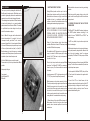
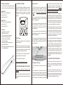
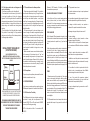
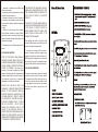
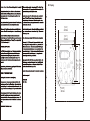
Foremost Technology for Absolute Acoustic Reproduction
International:
B-Band Ltd
Konttisentie 8 B,
40800 Vaajakoski, FINLAND
Tel: +358 14 332 9050
Fax: +358 14 332 9001
Email:[email protected]
Internet: www.b-band.com
USA:
B-Band, Inc.
2009 Ranch Road 620 North, #820
Austin, TX 78734
Tel:(512) 266-3820
Fax:(512) 266-7203
Email:[email protected]
Internet: www.b-band.com
Germany:
B-Band GmbH
Fürstenrieder Str. 281
81377 München, GERMANY
Tel: +49-(0)89-990 176 41
Fax: +49-(0)89-990 176 42
Email:[email protected]
Internet: www.b-band.com
B-Band, B-Band logo, B35 are either registered trademarks or trademarks of B-Band Ltd in the United States and /
or other countries. Patented, patents pending. List of patents are available from B-Band Ltd upon request.
All specifications are subject to change without prior notice. All rights reserved. Copyright © 1996-2014 B-Band Ltd.
INSTALLATION MANUAL AND USER´S GUIDE
B-BAND B35 SIDEMOUNT PREAMP
WITH B-BAND UST TRANSDUCER
HZZLESS CIRCUIT ™
This is a basic installation manual and tip sheet. For more information, technical support,
and pictures of installations about B-Band products please check the B-Band website at
www.b-band.com or contact your B-Band dealer, distributor or B-Band directly.
2014-04-26 V2
DEAR CUSTOMER,
1. SAFETY AND PRODUCT CAUTIONS
Thank you very much for purchasing this state-of-the-art BBand® acoustic transducer system. B-Band takes care to
provide the highest quality product and is manufactured and
supported in true spirit of acoustic instrument aficionados.
The outstanding sound reproduction of B-Band transducers
is based on the technology of a very special, worldwidepatented material that is exclusive to B-Band. This material
is very different from, and has nothing to do with, piezoelectric films, transducers or pickups.
Before installation make sure instrument is in good working
condition.
Although B-Band products could be easy to install by
following these instructions carefully and checking the BBand website and references, we highly recommend the
installation be done by a professional qualified guitar
craftsman or technician. Some installations require a high
knowledge about woodworking and guitar structure.
When doing any drilling, sawing, cutting or routing at the
guitar, be sure to secure the guitar so it will not move when
doing such work.
2. OVERVIEW OF B-BAND UST AND AST PICKUP
TRANSDUCERS
B-BAND LTD, B-BAND, INC. AND B-BAND GMBH WILL
NOT BE RESPONSIBLE FOR ANY DAMAGES,
PERSONAL INJURIES OR LIABILITIES RESULTING
F R O M I N S TA L L AT I O N S , I M P R O P E R LY D O N E
INSTALLATIONS OR MISUSE OF PRODUCT.
How is it different? A long story could be written about the
technical characteristics of the material, like how the
“microscopic lens-like gas bubbles”™ work inside the
permanently charged film, but the most important difference
is the sound. Whereas piezo pickups tend to impart a sound
of their own (often described as “quacky” or “plastic”), BBand transducers act in much the same way a condenser
microphone does. B-Band systems will provide an excellent
reproduction of your instrument's unique sound.
The B-Band UST (Under-Saddle Transducer) pickup uses
the EMFIT® patented transducer technology. In this
booklet, the terms “TRANSDUCER” and “PICKUP” are
alike in meaning.
The UST is very flexible, but you should never pull or bend
them at a sharp angle.
Read all of these instructions closely before starting
installation. B-Band A and H series UST transducer pickups
work with all B-Band A-series preamps.
UST
All of us at B-Band truly hope you enjoy this product.
Please contact us if you have any comments about B-Band
products.
B-Band pickups themselves do not require electrical power,
as they are permanently charged electrets. Because of the
very high output impedance (typical for condenser
microphones) The B-Band UST always require a B-Band
preamp.
After installation the UST pickup can have very high output,
enough to overdrive the B-Band preamp input, causing
distortion. The UST will lower in output, under pressure of
the saddle, in 1 to 3 days.
Standard piezo preamps will not work properly with B-Band
pickups. This kind of device combination will produce low
output and poor bass response.
Do not cut, pull, crimp or bend at a sharp angle any B-Band
transducers. The B-Band UST CANNOT be shortened or
altered in any way. This will cause audible hum and void
the warranty.
Always ready to help you.
Yours sincerely,
Heikki Räisänen, CEO
B-Band Ltd
The active portion of the B-Band 29R UST pickup is 80 mm
(3”) from the end of the transducer at the opposite side of
the connector.
Long-time exposure of UST to high temperatures (over 50
°C / 120 °F) may reduce the output level permanently.
The rest of the UST is not active. However, for best
performance always keep the inactive portion of either UST
pickup from touching or rubbing on the inside of the guitar,
or touching the battery or output jack wires. These can
produce unwanted handling noise.
B-Band preamps are active devices powered by battery.
The active preamp has a higher signal output and functions
differently from passive circuits, for example, that is found
on electric guitar. When using an active preamp do not turn
the volume, or tone controls all the way up to full as this
could very easily overdrive the input of an amplifier or mixer
causing distortion. Use moderate levels when operating.
B35
2
B-Band pickups will only work with B-Band preamps. BBand preamps will work with most any external audio
preamps, mixers, instrument amplifiers, and most other
audio devices.
3
UST Models and Specifications:
For use with steel and nylon stringed guitars, ukulele and
instruments that have similar saddle and bridge structures.
Model 29R UST:
29R- 2.9mm / 1/8”: wide saddle slots.
Active area: 80mm / 3”
Overall length: 330mm / 13”
3. OVERVIEW OF B35 PREAMP
Drilling hole for UST
The B-Band B35 preamp is designed to give optimum
performance with B-Band UST transducer. The main
criterion in designing these preamp was to deliver
professional musical sound quality and user-friendly
electronics to the diverse needs of acoustic instrument
musicians.
For UST check the inside of the instrument to find the
position of the braces. Drill a preferably 30 - 45 degrees
angled, 2.6 mm (.10”) for the transducer into the one end of
the saddle slot. Be careful not to damage any internal
braces!
to check inside the instrument body that there is enough
clearance for the preamp at the side between the
soundboard and the back of the instrument. Be sure to
check that the pickup will reach the preamp from its
position under the saddle and bridge area.
The sides of the instrument where the preamp will be
installed should be inspected for accessibility and stability.
Inside some instruments there is kerfed lining (the wood
reinforcement between the back and sides inside the
guitar) and other reinforcements that may make the area
too small to install the preamps. If these reinforcements are
altered it may cause instability at the instrument's side.
In case you cannot make the hole angled, because of
possible damage to the braces, you can make it straight
down in a 90-degree angle.
Model 22R UST:
22R- 2.2mm / 3/32”: narrow saddle slots.
Active area: 80mm / 3”
Overall length: 330mm / 13”
It is very important to smooth the edge of the hole using a
bit of rolled sandpaper or a small file, so there is not a
sharp edged corner, to avoid pinching or crimping the UST
as the saddle lies on it.
UST Features:
• Operation based on the exclusive
B-Band / Emfit electret film
• UST has two sizes that will fit most guitars
• Reproduces the original tone without
affecting the instrument acoustically
• Ultra-thin and lightweight
• Wide dynamic range and frequency response
• High gain before feedback
• Easy and fast plug-in installation without soldering
• No or minimal modification
Instruments with solid sides or that have very thin sides
may not be stable after cutting a hole to fit the preamp. It
may be necessary to reinforce this area from the inside of
the instrument with an extra piece of plywood before cutting
or drilling holes. If needed glue in a piece of plywood of
suitable thickness to reinforce that area.
In case you cannot make the hole angled, because of
possible damage to the braces, you can make it straight
down in a 90-degree angle.
The B35 Preamp
It is very important to smooth the edge of the hole using a
bit of rolled sandpaper or a small file, so there is not a
sharp edged corner, to avoid pinching or crimping the UST
as the saddle lies on it.
T10has a special 6.3 mm (¼”) output jack that when a ¼”
plug is inserted turns on the 9-volt power.
Cover the planned installation area with masking tape and
mark the area with a pencil using the provided preamp
hole-cutting template at the end of these instructions.
Prepare the instrument for cutting the preamp hole by
securing it in some way so that the guitar does not move
while doing the cutting. For best cutting results, use a
routing tool. Do this slowly and very carefully so the cutting
tool does not accidentally move outside the area that you
have marked with the guide. Smooth the edges of the
finished hole with a small file or sand paper and remove the
masking tape.
The T35 is powered by 9-volt power.
5. CONNECTING THE PICKUP TO THE PREAMP.
The B35 has the HzzLess® circuit for outstanding low
noise and high output.
The B35 is a side mount preamp with a volume and tone
control, chromatic tuner, tuner button, low battery LED light
and a battery compartment at the faceplate. This single
input preamp is for use with the UST pickup.
For operation of the B35 see the User's Guide.
4. PREPARING THE INSTRUMENT FOR INSTALLATION
Please read completely before starting the actual
procedure.
Remove the strings and the saddle. Check that the UST fits
into the slot easily and that the saddle is sufficiently tight in
the slot.
4
Connect the pickup. Notice that the small holes on the
connector of the pickup should point upwards when
connecting. If UST is connected improperly a loud audible
hum will occur.
Making holes for T35 preamp
Find the B35 preamp cut hole plans at the back of this
book.
The pickup is inserted onto the pickup “tunnel” and
connected to two pins at the end of the tunnel. Using a
screwdriver, or similar tool, carefully and easily push on the
plastic connector until the end of the travel. Do not push
hard as it is well connected at the end of travel.
Find a good position for the preamp at the side of the
instrument. Be sure that the position is so that when the
holes are made the holes, and the preamp structure when
installed, do not interfere with the any of the instrument
braces or supports. For this installation it is very important
5
When the pickup is connected to preamp it is
recommended to test the systems operation at this point.
nut and the small dress washer from the output jack. Make
sure that the large nut; lock washer and large dress washer
are threaded onto the jack almost all the way to the
opposite end of the output of the jack.
Insert the batteries and connect the output cable to
amplifier. You should hear it from the amplifier when you
tap on the pickup. Remove the batteries for the rest of the
installation.
Next, test-fit the jack the endpin hole. It is easier to install
the output jack by using an ink pen (or something similar)
that fits into the jack.
B35
Put the pen through the hole at the instrument where the
jack will go and with the other hand holding the output jack,
and that going through the sound hole, put the jack on the
pen and guide it through the hole of the instrument. Adjust
the large nut so that only the smaller threaded section
comes almost entirely out of the guitar. Put the dress
washer and the small nut onto the threads outside the
instrument. Tighten securely using an appropriate wrench.
Prevent the jack from rotating during tightening by inserting
a small Allen wrench into the holes of the end of the jack.
Install the strap attachment.
6. INSTALLING THE PREAMP.
Be careful not to over-tighten it, it just needs to be snug.
For the next portion of the installation, be careful not to
catch the pickup on anything as you work. Inadvertent
tugging may cause damage to the pickup or pull the
connector off the connections at the preamp.
7. INSTALLING THE PICKUP
Thread the B-Band UST up from inside the instrument
through the hole in the saddle slot. The UST pickup has the
EZ Hole-Through™ feature, which is a small hole at the
end of the pickup to make it easier to tread through the hole
at the saddle slot. Simply take an unwound steel string or
wire, make a small bend no bigger than the hole that the
pickup goes through. Put the wire through the
For the B35, take the pickup and the output jack and
harness through the hole for the preamp and mount the
preamp.
Let the pickup and wire harnesses hang loose inside the
instrument. Install the screws for the preamp faceplate. It is
important that you have a good quality screwdriver to avoid
it slipping during tightening and thus scratching the guitar.
Be careful to tighten the screws properly. It may be wise to
tape the area around the preamp faceplate with masking
tape in case you slip with the screwdriver. Do not overtighten the screws as it may strip the screws, or crack the
side of your instrument or the preamp's faceplate.
For the B35, if the output jack is the endpin type with strap
attachment, unscrew the strap attachment, the small
6
8.3. Resonance or distortion with some played notes.
After installation the UST pickup can have very high output,
enough to overdrive the B-Band preamp input, causing
distortion. The UST will lower in output, under pressure of
the saddle, in 1 to 3 days.
Install the batteries and test the system before putting on
the strings. To do this, plug into an amplifier and then tap
lightly on the top of the instrument to make sure that you
can hear the pickup when you tap.
There are a couple places where a resonance can typically
occur with some notes, causing distorted-sounding output.
First, check that the lead portion of the transducer to the
preamp is not touching anything and that the battery or
output wires are not loose and thus cause resonance.
Another good test is to shake the instrument when plugged
into amplifier. If anything is loose or if the transducer's
leads are touching something you will hear it. This should
not happen.
With the UST, another place, which in some cases has
caused resonance, is the UST hole from the saddle slot to
the inside of the instrument. Using a soft padding in it has
cured these problems effectively.
8 TROUBLESHOOTING
8.4. Imbalance, one or several strings sound louder or
quieter than the others (with UST)
If there's only a very slight imbalance, let the saddle
“shape” on the UST for a few days. The fault may be
repaired on its own. Users have reported that after three (3)
days the saddle has settled on the UST and the balance
becomes perfect.
8.1. No sound at all or intermittent sound
- Check the guitar cable and amplifier / mixer you are
using.
- Check that the battery is not discharged. If the sound is
noisy or distorted, replace the batteries.
- Check all preamp, output jack and battery box
connections
- Check that the transducer is inserted all the way and onto
the pin headers of the preamp correctly.
Fit the UST all the way to the other end and bottom of the
slot. Then put the saddle in place.
8.2. Loud hum
8.5. Possible reasons for imbalance:
- The saddle or the bottom of the saddle slot is not flat.
- The saddle fits too loosely in its slot.
- The saddle slot might be too tight for the saddle to go in
all the way. Try pushing on the saddle firmly to seat the
saddle all the way down on the transducer.
- The saddle is too short.
- There is debris in the saddle slot.
- The angle of some of the strings behind the saddle is too
low or too high.
- The top of the instrument is bent.
- The pickup is not installed all the way to the end of the
saddle slot.
- If the material of the saddle is bone.
Note! After installation the UST pickup can have very high
output, enough to overdrive the B-Band preamp input,
causing distortion. The UST will lower in output, under
pressure of the saddle, in 1 to 3 days.
- Check to see that the connectors of the UST are inserted
with the two holes up. If these connectors are upside down
the system will work but it will buzz.
Check that the connectors are inserted correctly onto their
pin headers at the preamp.
Bone is a natural material and the density and grain may
not be consistent. This may cause inconsistencies in the
way the sound is distributed making some strings louder or
softer than others. We highly recommend a manmade
material for the saddle.
pickup hole from the top of the instrument to the interior
and attach to the hole at the pickup then pull the wire with
the pickup up through the hole.
For the B35 if the output jack is the type for side mounting,
install the output jack.
Inside the instrument, make sure that the UST lead does
not touch anything. We do not recommend attaching the
“lead” wires of the UST to the instrument by any means.
This may cause excessive handling noise and resonance
that sounds like distortion.
Install the strings and test the system.
Now play, keep it real and enjoy!
- Check that the plug is making good connection with the
output jack. It may be so that the output jack is not sticking
out far enough when the strap button is on. To check,
unscrew the strap button off and plug in to the jack. If the
symptoms go away the output jack needs to be removed
and the nuts adjusted so the jack sticks out further.
7
8.6. If the balance problem does not disappear on its
own, do the following:
- Check there is no debris or paint in the saddle slot.
- Check saddle that it is not too loose or tight in its slot. If it
is too loose the saddle can tilt when the strings are
tightened. The tilt will bring the bottom of the saddle off the
pickup causing balance problems. If it is too tight it could be
possible the saddle is not going all the way down on the
pickup making a bad connection and causing balance
problems.
- Check the bottoms of both the saddle slot and saddle.
They should be flat and straight. If all things mentioned
above are correct, and there still is a balance problem, try
the following simple modification:
8.7. Other notable causes for balance problems
- Check string angles behind the saddle. They should be
about the same behind every string. If the angle is too low,
the string will not put enough pressure on the transducer
and that may cause balance problems - usually higher
output from the corresponding string. To deepen the angle,
you can, for example, file a wedge-shaped groove on the
bridge pinhole so that the string will have deeper angle
behind the saddle.
- With some instruments the outer most strings are too
close to the edge of the saddle, causing balance problems
to these strings. It may happen that the E string at the end
of the UST does not come as loud as other strings. In this
case, make another, shallow hole (not all the way through)
at that end of the saddle cavity and move the pickup so the
tip of the UST goes in the hole. If nothing else helps, you
should machine the saddle slot longer and use a new
longer saddle.
- Another somewhat common cause for balance problems
is the movement of the instrument top as it “lives” and
moves especially during transport or by change of season
when the humidity changes. Because of this the bottom of
the saddle slot could become arched, not straight, as the
top becomes more or less arched. By making the saddle
flexible this problem can be avoided.
INSTALLATION OF THE B-BAND UST
(UST WITH FIXED SHIM)
SADDLE EDGE MODIFICATIONWHENTHERE IS STRING BALANCE AND SIGNAL
OUTPUT PROBLEMS DO THIS MODIFICATION TO THE
SADDLE.
String
8.8. Other problems
Saddle
(side view)
Bridge
(side view)
If you notice any other problems, please contact the dealer,
distributor or manufacturer, for help.
SHIM
UST
9. CUSTOMER FEEDBACK
If you have any comments, positive or negative, about any
B-Band product, please do not hesitate to contact B-Band.
USING SANDPAPER OR FILE, SHAPE BOTTOM EDGES
AT LENGTH OF THE SADDLE TO LOOK LIKE THIS.
NO MORE THAN 0.5mm SHOULD BE TAKEN AWAY.
10. EU / Declaration of Conformity
This B-Band product has been designed, manufactured
and tested to comply with the requirements of EMC
directive 89/336/ EEC and CE mark directive 93/68/EEC
and carry the CE marking accordingly.
THE SHIM SHOULD BE BETWEEN THE UST AND THE
SADDLE BRIGDE. THE FLAT SIDE OF THE SHIM IS FIXED
ON THE UST. THEROUND SIDE OF THE SHIM IS
TOUCHING THE SADDLE BRIDGE
Statement of EU Declaration of Conformity is available
from manufacturer upon request.
3. This guarantee does not cover:
a) periodic maintenance and repair or parts replacement
due to wear and tear.
B-BAND LIMITED WARRANTY STATEMENT
b) consumables (components that are expected to require
periodic replacement during the lifetime of a product)
In the unlikely event that your product needs guarantee
service, please contact your dealer, distributor or
manufacturer. To avoid any unnecessary inconvenience on
your part, we recommend you read this instruction manual
carefully before seeking guarantee service.
c) damage or defects caused by use, operation or
treatment of the product inconsistent with normal use
YOUR GUARANTEE
d) damage or changes to the product as a result of:
By this Guarantee, B-Band guarantees the product to be
free from defects in materials and workmanship at the date
of original purchase for a period of one (1) year from that
date.
1. misuse, including:
- treatment resulting in physical, cosmetic or surface
damage or changes to the product
- failure to install or use the product for its normal purpose
or in accordance with B-Band's instructions on installation
or use
If within the guarantee period the product is determined to
be defective (at the date of original purchase) due to
improper materials or workmanship, B-Band will, without
charge for labor or parts, repair or (at B-Band's discretion)
replace the product or its defective parts subject to the
terms and limitations below. B-Band may replace defective
products or parts with new or refurbished products or parts.
All products and parts replaced become the property of BBand.
- failure to maintain the product in accordance with BBand's instructions on proper maintenance
- installation or use of the product in a manner inconsistent
with the technical or safety laws or standards in the country
where it is installed or used
2. the condition of or defects in systems with which the
product is used or incorporated except other B-Band's
products designed to be used with the product
TERMS
1. Guarantee services will be provided only if the original
invoice or sales receipt (indicating the date of purchase,
model name and dealer's name) is presented with the
defective product within the guarantee period. B-Band may
refuse free-of-charge guarantee service if these documents
are not presented or if they are incomplete or illegible. This
Guarantee will not apply if the model name or serial
number on the product has been altered, deleted, removed
or made illegible.
3. use of the product with accessories, peripheral
equipment and other products of a type, condition and
standard other than prescribed by B-Band
4. repair or attempted repair by persons who are not BBand employees
2. This Guarantee does not cover transport costs and risks
associated with transport of your product to and from BBand.
LED's in this product are Class 1 in accordance to EN
60825-1.
8
9
5. adjustments or adaptations without B-Band's prior
written consent, including:
- upgrading the product beyond specifications or features
described in the instruction manual, or
- modifications to the product to conform it to national or
local technical or safety standards in countries other than
those for which the product was specifically designed and
manufactured
6. neglect
7. accidents, fire, liquids, chemicals, other substances,
flooding, vibrations, excessive heat, improper ventilation,
power surges, excess or incorrect supply or input voltage,
radiation, electrostatic discharges including lighting, other
external forces and impacts.
THROUGH DEFECTS OR UNAVAILABILITY WHILE WITH
B-BAND, WHICH CAUSED DOWNTIME, LOSS OF USER
TIME OR BUSINESS INTERRUPTION INACCURACY OF
OUTPUT FROM THE PRODUCT OR ASSOCIATED
PRODUCTS.
THIS APPLIES TO LOSS AND DAMAGES UNDER ANY
LEGAL THEORY, INCLUDING NEGLIGENCE AND OTHER
TORTS, BREACH OF CONTRACT, EXPRESS OR
IMPLIED WARRANTY, AND STRICT LIABILITY (EVEN
WHERE B-BAND HAS BEEN ADVISED OF THE
POSSIBILITY OF SUCH DAMAGES).
Where applicable law prohibits or limits these liability
exclusions, B-Band excludes or limits its liability only to the
maximum extent permitted by applicable law.
4. This guarantee covers only hardware components of the
product.
For example, some countries prohibit the exclusion or
limitation of damages resulting from negligence, gross
negligence, willful misconduct, deceit and similar acts. BBand's liability under this guarantee will in no case exceed
the price paid for the product, but if applicable law permits
only higher liability limitations, the higher limitations apply.
EXCLUSIONS AND LIMITATIONS
EXCEPT AS STATED ABOVE, B-BAND MAKES NO
WARRANTIES (EXPRESS, IMPLIED, STATUTORY OR
OTHERWISE) REGARDING PRODUCT PERFORMANCE,
ACCURACY, RELIABILITY, FITNESS FOR A PARTICULAR
PURPOSE, OR OTHERWISE. If this exclusion is not
permitted or fully permitted by applicable law, B-Band
excludes or limits its warranties only to the maximum extent
permitted by applicable law. Any warranty that cannot be
fully excluded will be limited (as far as permitted by
applicable law) to the duration of this Guarantee.
YOUR LEGAL RIGHTS RESERVED
Consumers have legal (statutory) rights under applicable
national laws relating to the sale of consumer products.
This guarantee does not affect statutory rights you may
have nor those rights that cannot be excluded or limited,
nor rights against the person from whom you purchased
the product. You may assert any rights you have at your
sole discretion.
B - B A N D ' S O N LY O B L I G AT I O N U N D E R T H I S
GUARANTEE IS TO REPAIR OR REPLACE PRODUCTS
SUBJECT TO THESE GUARANTEE TERMS AND
CONDITIONS. B-BAND IS NOT LIABLE FOR ANY LOSS
OR DAMAGE RELATING TO PRODUCTS, SERVICE,
THIS GUARANTEE OR OTHERWISE, INCLUDING ECONOMIC OR INTANGIBLE LOSSES – THE PRICE
PAID FOR THE PRODUCT - LOSS OF PROFITS,
REVENUE, DATA, ENJOYMENT OR USE OF THE
PRODUCT OR ANY ASSOCIATED PRODUCTS INDIRECT, INCIDENTAL OR CONSEQUENTIAL LOSS OR
DAMAGE. THIS APPLIES WHETHER THAT LOSS OR
DAMAGE RELATES TO: IMPAIRED OR NON-OPERATION
OF THE PRODUCT OR ASSOCIATED PRODUCTS
10
11
B35 Opening
[1.94”]
49.50mm
[1.81”]
46.20mm
12
[1.67”]
42.50mm
[1.50”]
38.20mm
[0.079”]
Φ2.0mm