1
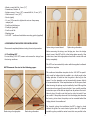
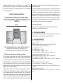
A2 INSTALLATION MANUAL B-BAND A2 END PIN PREAMP EQUIPPED WITH HZZLESS™ CIRCUIT. USE WITH B-BAND UST AND AST TRANSDUCERS, AG-MIC, MAGNETIC PICKUP USE WITH STEEL OR NYLON STRING GUITARS, OR OTHER SUITABLE INSTRUMENTS. This is a basic installation manual and tip sheet. For more information, technical support and pictures of installations for B-Band products please check the B-Band website www.b-band.com or contact your B-Band dealer, distributor or B-Band directly. 25.3.2009 DEAR CUSTOMER, Thank you very much for purchasing this state-of-the-art B-Band® acoustic transducer system. B-Band takes care to provide the highest quality product and is manufactured and supported in true spirit of acoustic instrument aficionados. The outstanding sound reproduction of B-Band transducers is based on the technology of a very special, worldwide-patented material that is exclusive to B-Band. This material is very different from, and has nothing to do with, piezo-electric films or transducers. How is it different? We could write a long story here about the technical characteristics of the material, like how the “microscopic lens-like gas bubbles”™ work inside the permanently charged film, but the most important difference is the sound. Whereas piezo pickups tend to impart a sound of their own (often described as “quacky” or “plastic”), B-Band transducers act in much the same way a condenser microphone does. B-Band systems will provide an excellent reproduction of your instrument’s unique sound. All of us at B-Band truly hope you enjoy this product. Please contact us if you have any comments about B-Band products. Always ready to help you. Yours sincerely, Heikki Räisänen, CEO B-Band Ltd A2 AG-MIC 1. SAFETY AND PRODUCT CAUTIONS Although B-Band products could be easy to install by follow ing these instructions carefully and checking the B-Band web site and references, we highly recommend the installation be done by a professional qualified guitar craftsman or technician. Some installations require a high knowledge about woodwork ing and guitar structure. B-BAND LTD, B-BAND, INC. AND B-BAND GMBH WILL NOT BE RESPONSIBLE FOR ANY DAMAGES, PERSONAL INJURIES OR LIABILITIES RESULTING FROM INSTALLATIONS, IMPROPERLY DONE INSTALLATIONS OR MISUSE OF PRODUCT. 2. OVERVIEW OF B-BAND UST AND AST PICKUP TRANSDUCERS Read all of these instructions closely before starting installation. Both the B-Band UST (Under-Saddle Transducer) and AST (Acoustic Soundboard Transducer) pickups use the same-pat ented transducer technology. B-Band pickups (UST and AST) work with all B-Band A-series preamps. The UST and AST are very flexible, but you should never pull or bend them at a sharp angle. After installation the UST pickup can have very high output, enough to overdrive the B-Band preamp input, causing distortion. The UST will lower in output, under pressure of the saddle, in 1 to 3 days. B-Band pickups themselves do not require electrical power, as they are permanently charged electrets. Because of the very high output impedance (typical for condenser microphones) BBand UST and AST always require a B-Band preamp. Do not cut, pull, crimp or bend at a sharp angle any B-Band transducers. B-Band UST and AST CANNOT be shortened or altered in any way. This will cause audible hum and void the warranty. Long-time exposure of UST or AST to high temperatures (over 50 °C / 120 °F) may reduce the output level permanently. B-Band pickups will only work with B-Band preamps. B-Band preamps will work with most any external audio preamps, mixers, instrument amplifiers, and most other audio devices. Before installation make sure instrument is in good working condition. Do not mount battery holder to preamp. Even with the battery secure in the holder or the battery box lid closed, the battery could get loose when transported. We strongly recommend removing the battery before transporting the instrument in heavy conditions, for example, with freight companies or airlines, to avoid possible damage to the instrument. When doing any drilling, sawing, cutting or routing at the guitar, be sure to secure the guitar so it will not move when doing such work. Standard piezo preamps will not work properly with B-Band pickups. This kind of device combination will produce low output and poor bass response. The active portion of the B-Band UST pickup is 80 mm (3.15”) from the end of the transducer at the opposite side of the con nector. The active portion of the 1470 AST is the 14 x 70 mm (.55” x 2.75”) area that attaches to the guitar. The rest of the UST and the “lead” wire of the AST are not active. However, for best performance always keep the inactive portion of either UST or AST pickup from touching each other, or touching or rubbing on the inside of the guitar, or touching the battery or output jack wires. These can produce unwanted handling noise. UST and Model sizes: Saddle width: 2.3 – 2.9 mm (.090” - .115” (3/32”)) use B-Band model #: 22R UST width: 2.3 mm (.090” (3/32”)) Saddle width: 3.0 mm (.118” (1/8”)) or more use B-Band model #: 29R UST width: 3.0 mm (.118” (1/8”)) 3. OVERVIEW OF A2 PREAMP sant body tone to the mix with a UST or AST pickup The AG-MIC should be used sparingly in a sound mix. All B-Band A-series preamps are designed to give optimum performance with B-Band UST and AST transducers. The main criterion in designing these preamps was to deliver studio qual ity and user-friendly electronics to the diverse needs of acoustic instrument musicians. 4. PACKAGE CONTENTS The A2 is a two input / two output endpin preamp. Designed as a platform for two sources, the best performance is with the combination of UST and AST. The #1 channel input can support UST or AST pickup. 4.1 UST package contents: • 1 pc UST pickup Note! In the USA, transducers and preamps are packaged together. 4.2 AST package contents: • 1 pc AST pickup • 1 pc cardboard installation guide (only AST) The #2 channel input can support a UST or AST pickup, or can also be configured for use with the B-Band AG-MIC condenser microphone or a passive magnetic pickup with the mini dipswitches inside the A2. The A2 uses a custom endpin jack that allows either standard 1/4” mono or stereo plug to turn on the 9-volt power. DO NOT PHANTOM POWER B-BAND A2 PREAMPS! 4.3 A2 package contents: • 1 pc A2 preamp circuitry board • 1 pc A2 preamp box • 1 pc A2 preamp box back • 2 pc screws for preamp box • 1 pc A2 preamp with strap button assembly • Strap button assembly includes: - Small hex nut - Small dress washer - Lock washer - Large dress washer - Large hex nut • 1 pc battery clip with adhesive • 1 pc battery cable harness • 2 pcs wire clamps • 1 pc instructions and user guide 3.1 OPTIONAL AG-MIC CONDENSER MICROPHONE FOR A2 PREAMP 4.4 AG-MIC package contents: • 1 pc AG-MIC condenser microphone The B-Band AG-MIC microphone option is an excellent choice and value for an additional condenser microphone. The mic capsule is especially designed for acoustic instruments, with suitable bass roll-off and treble boost. This is not a full range microphone. The AG-MIC’s use is primarily to add some plea- 5. TOOLS AND MATERIALS NEEDED FOR INSTALLATION • Drill, preferably with continuously variable speed • Wood or metal drill bit, 2.3 mm (.09”) or 3 mm (.12”), depending on the width of the transducer With the A2 you will need a two channel (stereo) Y-cable (TRS plug to 2 mono plugs) in order access the two output channels. 1/4” (STEREO) (MONO) 1/4” (MONO) 1/4” The two outputs will allow control of the mix between the two outputs at a mixer or amplifier. With a standard guitar cable the output will be that of channel 1 only (normally the UST). • Wood or metal drill bit, 3 mm (.12”) • Screwdriver, Posidriv #1 • Endpin reamer, 12 mm (.47”) or wood drill bit, 12 mm (.47”) • Allen wrench, 2 mm (.08”) • Punch (spike) • 13 mm (.51) wrench to tighten the nuts on the preamp endpin jack • Small hand-held mirror • Flashlight (penlight) • Small round file • Masking tape • 1470 AST – cardboard installation mounting guide (supplied) 6. PREPARING THE GUITAR FOR INSTALLATION Nylon string at sound board Please read completely before starting the actual procedure. Nylon string alternative Before removing the strings and bridge pins from the bridge check to see if the AST will fit at the bridge plate correctly. Also at this time, clean the bridge plate surface with a moist cloth and let dry completely. 6.1 Test fitting AST For test fitting 1470 AST, loosen and remove the strings from the tuning machines. The AST can be mounted by hand or with the supplied cardboard installation template. AST Placement. See text at the following pages. The cardboard installation template for the 1470 AST is specifi cally made for bridges that the saddle is at a slight angle to the bridge pinholes. It could be that the guide is too long for the space. If so, the template can be trimmed with scissors slightly to accommodate this. If the template does not fit the space, even after trimming, the pickup may be installed by hand. Although the instructions do not specify how to do this, if you carefully read the instructions you will be able to adapt them to perform the installation by hand. It really is not that hard or critical to install if you are careful. If the pickup does not fit to the bridge plate because the bracing is too close, the pickup can be mounted behind the bridge plate at the soundboard. Steel string at bridge plate For classical guitars the installation the AST is done by hand without the guide. For most classical guitars the AST is placed inside the guitar parallel to center brace that runs parallel to the Steel string alternative strings on the bass strings side at the area between the bridge and soundhole. Sometimes there is also a flat brace running parallel under the bridge. The AST should be placed so that the AST is on the bass side of the brace running parallel to the strings and that part of the active area of the AST, that has the lead to the preamp, goes on the brace for the bridge. If the brace there is too tall put the AST in front of the brace. Please read the instructions carefully and adapt them to the installation. If the guitar does not have a strap button pin and no hole, then a 12mm will have to be drilled with wood drill bit. We recommend that a professional should do this. Put a piece of masking tape where the hole will be drilled. This makes it easy to draw a point where to start drilling. Use the punch to make a start hole. Use a very small drill bit to make a starter hole and then finish by using the 12mm (.47”) drill bit. Smooth the edge of the hole with a small file or a sinking drill bit. To test fit the 1470 AST in a guitar with a bridge plate, take the cardboard installation template from the tray in the box. Note! There is a small 4.5 mm (.18”) round and a 4.5 mm (.18”) elongated part that both need to be punched out to make their respected guide holes. The 4.5 mm round guide hole is for the low “E” bridge pin and the elongated guide hole to fit at the high “E” bridge pin inside the guitar. Peel away the protective covers from the two adhesive dots on the cardboard. Do not peel away the actual AST mounting adhesive protective cover yet! 6.4 Drilling hole for UST For UST check the inside of the guitar to find the position of the braces. Drill a preferably 30 - 45 degrees angled, 2.3 mm (.09”) or 3 mm (.12”) hole (depending on the model of your B-Band UST) for the transducer into the one end of the saddle slot. Be careful not to damage the braces! The placement of the AST is important for connection to the preamp. For the A2 preamp, the AST’s lead goes away from the high “E” side of the bridge area and towards the strap pin at the butt end of the guitar It is very important to smooth the edge of the hole using a bit of rolled sandpaper or a small file, to avoid pinching the UST as the saddle lies on it. It is preferred, that the hole for the UST is drilled at the low-E string side of the slot. Now mount the AST to the top of the cardboard installation template at the rectangle AST area inscribed on the cardboard. Now put the assembly to the bridge pins, with the AST towards the bridge plate and check the fit. All of the AST’s active area must fit at the soundhole side of the bridge plate without hang ing over the edge of the bridge plate. Make sure that there is enough space that the bridge pins or string ball-ends will not touch the AST. 6.5 Installing battery holder Before installing the battery holder it should be checked by in serting a 9-volt battery in and out of it to learn how it works. Once this is checked, find a convenient place inside the guitar where the battery holder can be reached and that there is good access to the snap. Also check that it is in a place that the bat tery can be put in and out easily. In case you cannot make the hole angled, because of possible damage to the braces, you can make it straight down. Recommended places are at the neck block or at the back of the guitar. 6.2 Next remove the strings, bridge pins and the saddle. If you are using a UST, check that it fits into the slot easily and that the saddle is sufficiently tight in the slot. Be sure that the entire adhesive surface will make full contact with surface you are attaching it to. Clean the surface with a moist cloth and let the moist dry completely. Remove the pro tective liners of the adhesive and install it. Press firmly for about 30 seconds to make it secure. It takes 72 hours for the adhesive to achieve its final holding ability. 6.3 If the guitar has a strap button pin at the butt end of the guitar, remove it and carefully enlarge the hole using 12 mm (.47”) endpin reamer or 12 mm (.47”) wood drill bit. Smooth the edge of the hole with a small file or a sinking drill bit. A2 7. CONNECTING THE PICKUPS AND WIRING TO THE PREAMP NOTE! PIN HEADER POLARITY (IF INSTALLING MAGNETIC PICKUP) + 7.1 Open the preamp and see the picture for connections. Connect the pickup(s), AG-MIC, and battery cable harness. - AST, MIC or MAG PICKUP (Channel #2) Notice that the small holes on each connector of the transducer and battery cable harness should point upwards. #4 #3 #2 If the UST or AST are connected improperly, a loud audible hum will occur. Make sure that they are connected correctly. #1 7.2 Inside the A2 there are four DIP-switches: Switch #1 is an on-off switch for the treble boost on #1 channel (normally UST). Set that at on-position if you prefer a mild treble boost. UST or AST (Channel #1) Battery wire Switch #2 is an on-off switch for the #2 channel bass roll-off 6 dB (-3 dB @ 500 Hz when at on-position). Set it at the on-position only when using a condenser microphone to reduce low frequency feedback. 7.3. Close preamplifier enclosure 8. INSTALLING THE PREAMP For the next portion of the installation, be careful not to catch the pickups on anything as you work; inadvertent tugging may cause damage to the pickups or pull the connectors off the pin headers at the preamp. Switch #3 is an on-off switch for second channel bias-voltage (9-volt phantom power). Set it at on-position only when you use condenser microphone on the #2 channel. Switch #4 is an on-off switch for channel two gain reduction (27 dB at off, and 0 dB at on). This also must be set it at on-position when you use a condenser microphone or passive magnetic pickup connected to the #2 channel. For AST please note to lift one corner of the protective layer of the mounting adhesive so it is easier to remove later. 8.1 Unscrew the strap attachment, the small nut and the small dress washer from the endpin jack. Make sure that the large nut; lock washer and large dress washer are threaded onto the jack almost all the way to the opposite end of the output of the jack. From the factory, all the switches are set at off-position. Another option is that a magnetic pickup can be connected to channel #2 by soldering the pickup's wiring directly to the input pin headers. Check the polarity before installing. Use a low temperature soldering gun. Be careful to do this install and try not to heat up the pin headers. If too much heat, it is possible to melt the plastic or damage the circuit board. We recommend a professional luthier or guitar tech to do installation. 8.2 Next, test-fit the jack in your strap button-hole. Adjust the large nut so that only the smaller threaded section comes almost entirely out of the guitar. Put the dress washer and the small nut onto the threads outside the guitar. Tighten securely using an appropriate wrench. Prevent the jack from rotating during tightening by inserting a small Allen wrench into the holes If necessary, you can remove the AST shortly after attaching, but be careful when doing this. Carefully lift under the edge of the AST, with your fingernail, and work it off slowly. Don’t attempt to lift the AST off by pulling on the pickup lead. Peel the adhesive off the wood, rather than peeling the pickup off the adhesive. At installation this can be removed and reattached two or three times. of the end of the jack. Install the strap attachment. Be careful not to over-tighten it…it just needs to be snug. Connect a fresh 9-volt battery to the snap-in connector and put it in the battery holder. Attach the battery wires to the side of the guitar with the cord clamps. Roll the extra cord as a “coil” in some of the clamps if necessary. Inside the guitar, make sure that the UST or AST leads do not touch anything. We do not recommend attaching the “lead” wires of the UST or AST to the guitar by any means. This may cause excessive handling noise and resonance that sounds like distortion. 9 INSTALLING THE PICKUPS 9.1 Installing the UST. Thread the B-Band UST up from inside the guitar through the hole in the saddle slot. It is easier to find the hole inside the guitar if you insert a small screwdriver or toothpick from the top through the hole as a guide. Fit the UST all the way to the other end and bottom of the slot. Then put the saddle in place. Note! After 24 hours the adhesive will dry and it will be hard to remove. Removal after this time may damage the pickup. 9.3 If you are installing an A2 with the optional B-Band AG-MIC condenser microphone, install the mic at this point. There are a variety of possible locations, depending on your own taste and preferences. The two most used placements are: • Connect the mic near the intersection of the X-braces at the top and position the mic so that it points towards the soundhole at the strings. This will give a bright sound but may be more sensitive to feedback. • Connect the mic to a back brace and point the microphone so that it points to the top of the guitar behind the saddle. In this position the sound is warm and less sensitive to feedback. Note! After installation the UST pickup can have very high output, enough to overdrive the B-Band preamp input, causing distortion. The UST will lower in output, under pressure of the saddle, in 1 to 3 days. 9.2 For installation of the 1470 AST (steel string guitars; x-braces), place two bridge pins in their holes, one at the low “E” string side and one at the high “E” side. Set the bridge pins normally. This, with the cardboard installation template / AST assembly will guide the AST to fit correctly. Having the AST cardboard installation template / AST assembly lying on the bottom of the guitar, remove the adhesive protective layer from the AST. Lift the assembly up and guide the assembly so the bridge pins insert the guide holes and carefully place it to the bridge plate. Then stick it firmly by holding and pressing firmly with fingers for a short while. Next carefully remove the cardboard installation template. Make sure the AST fits there tight and secure. After attaching the mic, it is possible to adjust its direction in a wide range, simply by bending the metal wire. Bend it carefully to avoid making a sharp bend, as the paint could come loose. It will require some experimenting to find the optimal location for your particular guitar. Be patient and you’ll get a great sound. Attach the mic cable to the inside of guitar using the two supplied cable clamps. If needed, roll extra cable as a “coil” in one of the cable clamps. 9.4 Test the system before putting on the strings. To do this, plug into an amplifier and then tap lightly on the top of the guitar to make sure that you can hear the pickup when you tap. Another If installing AST by hand, remove the adhesive protective layer from the AST. Then stick it firmly into place by holding and pressing with fingers for a short while. good test is to shake the guitar when plugged into amplifier. If anything is loose or if the pickup’s leads are touching something you will hear it. This should not happen. With the AST, if resonance is occurring, it may be coming form the first 5 mm (.20”) of the “lead” wire coming from the AST. Using double stick tape, stick this first 5 mm (.20”) of the lead to the guitar. Install the strings and test the system. Now play, keep it real and enjoy! 10.4 Imbalance, one or several strings sound louder or quieter than the others (with UST) If there’s only a very slight imbalance, let the saddle “shape” on the UST for a few days. The fault may be repaired on its own. Users have reported that after three (3) days the saddle has settled on the UST and the balance becomes perfect. 10 TROUBLESHOOTING 10.1 No sound at all or intermittent sound • Check the guitar cable and amplifier / mixer you are using. • Check that the battery is not discharged. If the sound is noisy or distorted, replace the battery. • Check that the transducer and battery connectors are inserted onto the pin headers of the preamp correctly. • Check that the plug is making good connection with the output jack. It may be so that the output jack is not sticking out far enough when the strap button is on. To check, unscrew the strap button off and plug in to the jack. If the symptoms go away the output jack needs to be removed and the nuts adjusted so the jack sticks out further. 10.5 Possible reasons for imbalance: •The saddle or the bottom of the saddle slot is not flat. • The saddle fits too loosely in its slot. • The saddle slot might be too tight for the saddle to go in all the way. Try pushing on the saddle firmly to seat the saddle all the way down on the transducer. The saddle is too short. •There is debris in the saddle slot. • The angle of some of the strings behind the saddle is too low or too high. • The top of the guitar is bent. • The pickup is not installed all the way to the end of the saddle slot. • If the material of the saddle is bone. 10.2 Loud hum • Check to see that the connectors of the UST / AST are inserted with the two holes up. If these connectors are upside down the system will work but it will buzz. • Check that the connectors are inserted correctly onto their pin headers at the preamp. Bone is a natural material and the density and grain may not be consistent. This may cause inconsistencies in the way the sound is distributed making some strings louder or softer than others. We highly recommend a manmade material for the saddle. 10.3 Resonance or distortion with some played notes. After installation the UST pickup can have very high output, enough to overdrive the B-Band preamp input, causing distortion. The UST will lower in output, under pressure of the saddle, in 1 to 3 days. 10.6 If the balance problem does not disappear on its own, do the following: • Check there is no debris or paint in the saddle slot. • Check saddle that it is not too loose or tight in its slot. If it is too loose the saddle can tilt when the strings are tightened. The tilt will bring the bottom of the saddle off the pickup causing balance problems. If it is too tight it could be possible the saddle is not going all the way down on the pickup making a bad connection and causing balance problems. There are a couple places where a resonance can typically occur with some notes, causing distorted-sounding output. First, check that the lead portion of the transducer to the preamp is not touching anything and that the battery or output wires are not loose and thus cause resonance. With the UST, another place, which in some cases has caused resonance, is the UST hole from the saddle slot to the inside of the guitar. Using a soft padding in it has cured these problems effectively. else helps, you should machine the saddle slot longer and use a new longer saddle. • Balance problems may also occur with some string sets, for example with classical guitars the G-string may cause problems. • Another somewhat common cause for balance problems is the movement of the guitar top as it “lives” and moves especially during transport or by change of season when the humidity changes. Because of this the bottom of the saddle slot could become arched, not straight, as the top becomes more or less arched. By making the saddle flexible this problem can be avoided. Check the bottoms of both the saddle slot and saddle. They should be flat and straight. If all things mentioned above are correct, and there still is a balance problem, try the following simple modification: SADDLE EDGE MODIFICATIONWHEN THERE IS STRING BALANCE AND SIGNAL OUTPUT PROBLEMS DO THIS MODIFICATION TO THE SADDLE. String 11.8 Other problems If you notice any other problems, please contact the dealer, distributor or manufacturer, for help. 11. CUSTOMER FEEDBACK If you have any comments, positive or negative, about any B-Band product, please do not hesitate to contact B-Band. Saddle (side view) Bridge (side view) 12. A2 Specifications S/N ratio: Greater than -90 dB Distortion: 0,05 % Frequency response (both channels): 50 Hz - 40 kHz (-3 dB) Low-cut slope (both channels): -6 dB/octave Ch 1 voltage gain: +27 dB Ch 2 voltage gain: 0 / +27 dB Ch 1 input impedance: 50 MΩ || < 10 pF Ch 2 input impedance: 20 MΩ (2.2 kΩ with mic phantom on) Output impedance (both channels): 1 50 Ω Nominal output level (both channels): -10 dB u (0.245 Vrms) Mic bias voltage: 9 V through 2.2 kΩ Preset treble enhancer boost: +3 dB @ 6.3 kHz; +5 dB @ 1 4 kHz (when on) Power supply: 9-volt battery (not included) Current consumption: 1 .5 mA typical (2 mA with mic) Connections: Transducer inputs, 2.54 mm / .10” header; Output, 6.3 mm / 1/4” jack Weight (with accessories): 50 g Dimensions (incl. jack): W 32 mm / 1.25”, H 18 mm / .70” , L 82 mm / 3.20” USING SANDPAPER OR FILE, SHAPE BOTTOM EDGES AT LENGTH OF THE SADDLE TO LOOK LIKE THIS. NO MORE THAN 0,5 mm SHOULD BE TAKEN AWAY. 11.7 Other notable causes for balance problems • Check string angles behind the saddle. They should be about the same behind every string. If the angle is too low, the string will not put enough pressure on the transducer and that may cause balance problems - usually higher output from the corresponding string. To deepen the angle, you can, for example, file a wedgeshaped groove on the bridge pinhole so that the string will have deeper angle behind the saddle • With some instruments the outer most strings are too close to the edge of the saddle, causing balance problems to these strings. It may happen that the E string at the end of the UST does not come as loud as other strings. In this case, make another, shallow hole (not all the way through) at that end of the saddle cavity and move the pickup so the tip of the UST goes in the hole. If nothing 10 14. EU / Declaration of Conformity This B-Band product has been designed, manufactured and tested to comply with the requirements of EMC directive 89/336/ EEC and CE mark directive 93/68/EEC and carry the CE marking accordingly. B-BAND LIMITED WARRANTY STATEMENT In the unlikely event that your product needs guarantee service, please contact your dealer, distributor or manufacturer. To avoid any unnecessary inconvenience on your part, we recommend you read this instruction manual carefully before seeking guarantee service. YOUR GUARANTEE By this Guarantee, B-Band guarantees the product to be free from defects in materials and workmanship at the date of original purchase for a period of one (1) year from that date. If within the guarantee period the product is determined to be defective (at the date of original purchase) due to improper materials or workmanship, B-Band will, without charge for labor or parts, repair or (at B-Band’s discretion) replace the product or its defective parts subject to the terms and limitations below. B-Band may replace defective products or parts with new or refurbished products or parts. All products and parts replaced become the property of B-Band. TERMS 1. Guarantee services will be provided only if the original invoice or sales receipt (indicating the date of purchase, model name and dealer’s name) is presented with the defective product within the guarantee period. B-Band may refuse free-of-charge guarantee service if these documents are not presented or if they are incomplete or illegible. This Guarantee will not apply if the model name or serial number on the product has been altered, deleted, removed or made illegible. 2. This Guarantee does not cover transport costs and risks associated with transport of your product to and from B-Band. 3. This guarantee does not cover: a) periodic maintenance and repair or parts replace- ment due to wear and tear. b) consumables (components that are expected to require periodic replacement during the lifetime of a product) c) damage or defects caused by use, operation or treatment of the product inconsistent with normal use d) damage or changes to the product as a result of: i. misuse, including: - treatment resulting in physical, cosmetic or surface damage or changes to the product - failure to install or use the product for its normal purpose or in accordance with B-Band’s instructions on installation or use - failure to maintain the product in accordance with B-Band’s instructions on proper maintenance - installation or use of the product in a manner inconsistent with the technical or safety laws or standards in the country where it is installed or used ii. the condition of or defects in systems with which the product is used or incorporated except other B-Band’s products designed to be used with the product iii. use of the product with accessories, peripheral equipment and other products of a type, condition and standard other than prescribed by B-Band iv. repair or attempted repair by persons who are not B-Band employees v. adjustments or adaptations without B-Band’s prior written consent, including: - upgrading the product beyond specifications or features described in the instruction manual, or - modifications to the product to conform it to national or local technical or safety standards in countries other than those for which the product was specifically designed and manufactured vi. neglect vii. accidents, fire, liquids, chemicals, other substances, flooding, vibrations, excessive heat, improper ventilation, power surges, excess or incorrect supply or input voltage, radiation, electrostatic discharges including lighting, other external forces and impacts. 4. This guarantee covers only hardware components of the product. EXCLUSIONS AND LIMITATIONS EXCEPT AS STATED ABOVE, B-BAND MAKES NO WARRANTIES (EXPRESS, IMPLIED, STATUTORY OR OTHERWISE) REGARDING PRODUCT PERFORMANCE, ACCURACY, RELIABILITY, FITNESS FOR A PARTICULAR PURPOSE, OR OTHERWISE. If this exclusion is not permitted or fully permitted by 11 applicable law, B-Band excludes or limits its warranties only to the maximum extent permitted by applicable law. Any warranty that cannot be fully excluded will be limited (as far as permitted by applicable law) to the duration of this Guarantee. B-BAND’S ONLY OBLIGATION UNDER THIS GUARANTEE IS TO REPAIR OR REPLACE PRODUCTS SUBJECT TO THESE GUARANTEE TERMS AND CONDITIONS. B-BAND IS NOT LIABLE FOR ANY LOSS OR DAMAGE RELATING TO PRODUCTS, SERVICE, THIS GUARANTEE OR OTHERWISE, INCLUDING - ECONOMIC OR INTANGIBLE LOSSES – THE PRICE PAID FOR THE PRODUCT - LOSS OF PROFITS, REVENUE, DATA, ENJOYMENT OR USE OF THE PRODUCT OR ANY ASSOCIATED PRODUCTS - INDIRECT, INCIDENTAL OR CONSEQUENTIAL LOSS OR DAMAGE. THIS APPLIES WHETHER THAT LOSS OR DAMAGE RELATES TO: IMPAIRED OR NON-OPERATION OF THE PRODUCT OR ASSOCIATED PRODUCTS THROUGH DEFECTS OR UNAVAILABILITY WHILE WITH B-BAND, WHICH CAUSED DOWNTIME, LOSS OF USER TIME OR BUSINESS INTERRUPTION INACCURACY OF OUTPUT FROM THE PRODUCT OR ASSOCIATED PRODUCTS. THIS APPLIES TO LOSS AND DAMAGES UNDER ANY LEGAL THEORY, INCLUDING NEGLIGENCE AND OTHER TORTS, BREACH OF CONTRACT, EXPRESS OR IMPLIED WARRANTY, AND STRICT LIABILITY (EVEN WHERE B-BAND HAS BEEN ADVISED OF THE POSSIBILITY OF SUCH DAMAGES). Where applicable law prohibits or limits these liability exclusions, B-Band excludes or limits its liability only to the maximum extent permitted by applicable law. For example, some countries prohibit the exclusion or limitation of damages resulting from negligence, gross negligence, willful misconduct, deceit and similar acts. B-Band’s liability under this guarantee will in no case exceed the price paid for the product, but if applicable law permits only higher liability limitations, the higher limitations apply. YOUR LEGAL RIGHTS RESERVED Consumers have legal (statutory) rights under applicable national laws relating to the sale of consumer products. This guarantee does not affect statutory rights you may have nor those rights that cannot be excluded or limited, nor rights against the person from whom you purchased the product. You may assert any rights you have at your sole discretion. International: B-Band Ltd Konttisentie 8 FI-40800 VAAJAKOSKI FINLAND Tel: +358 14 332 9050 Fax: +358 14 332 9001 Email: [email protected] Internet: www.b-band.com USA: B-Band, Inc. P.O. Box 342394 Austin, Texas 78734 USA Tel: (512) 266 3820 Fax: (512) 266 7203 Email: [email protected] Internet: www.b-band.com Germany: B-Band GmbH Ofener Str. 19 80689 München Germany Tel: 089-990 176 41 Fax: 089-990 176 42 Email: [email protected] Internet: www.b-band.com B-Band, B-Band logo, A2, UST, AST, AG-MIC, HzzLess and “microscopic lens-like gas bubbles” are either registered trademarks or trademarks of B-Band Ltd in the United States and / or other countries. Patented, patents pending. List of patents are available from B-Band Ltd upon request. All specifications are subject to change without prior notice. All rights reserved. Copyright © 1996-2009 B-Band Ltd. 12