1
DVM 890L
LCD Standard Digital Multimeter
LCD Standaard Digitale Multimeter
Multimètre Digital LCD Standard
USER MANUAL
GEBRUIKERSHANDLEIDING
MANUEL D’UTILISATION
DVM 890L
LCD Standard Digital Multimeter
1. Introduction
This instrument is a compact, rugged, battery-operated hand-held 3 1/2 digit digital multimeter for
measuring DC and AC voltages, DC and AC current and resistance. It also offers the possibility of
executing continuity tests and of testing diodes and transistors. You can also measure capacitance
and temperatures.
The Dual-Slope A/D Converter uses C-MOS technology for auto-zeroing, polarity selection and
overrange indication. Full overload protection is provided. It is an ideal instrument for use in the
field, for laboratories and workshops, for hobby and home applications.
1.1 Features
*
*
*
*
*
*
*
*
*
*
*
Push-button ON/OFF power switch
30 different positions on the user-friendly rotary switch for FUNCTION and RANGE
High sensitivity : 100µV
Automatic overrange indication with the "1" displayed
Automatic polarity indication on DC ranges
All ranges fully protected
Resistance measurements 0.1Ω to 200MΩ
Capacitance measurements 1pF to 20µF
Diode testing with 1mA fixed current
Transistor hFE test with Ib = -100µA
Temperature measurement with or without K type thermocouple
1.2 A word about safety
This multimeter is designed to ensure the safest operation possible. However, safe operation
depends on you, the operator. Make sure you follow these simple safety rules :
• Never apply a voltage to the multimeter that exceeds the specified limits. Never apply more than
1000V DC or 700V rms AC between an input jack and ground.
• Use extreme caution when working with voltages above 60V DC or 30V AC rms.
• Always discharge the filter capacitors in the power supply circuit under test before attaching any
test leads.
• Never connect to a voltage source when selecting DCA, ACA, resistance measurement or the
continuity check function.
• Always turn off the power and disconnect the test leads before replacing the batteries or fuse.
• Never operate the multimeter unless the battery cover is in place and fully closed.
When carrying out measurements on TVs or switching power circuits, always remember that
there may be high amplitude voltage pulses at test points which may damage the meter.
DVM890L
1
GB
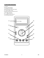
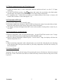
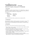
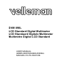
2. Front Panel description
1) Display
2) Power On/Off button
3) Transistor test socket
4) RANGE and FUNCTION switch
5) Capacity input sockets
6) Input connection temperature probe
7) mA-input connector
8) V/Ω-input connector
9) 20A MAX input connector
10) COM-input connector
DVM890L
ì
ó
ö
ú
÷
ø
í
û
ç
2
GB
2.1 Function and range selector
Various functions and 32 ranges are provided. A rotary switch is used to select functions as well as
ranges.
2.2 Power switch
A push-button is used to turn the meter on or off.
To extend battery life, an Auto Power-Off function is provided. The meter will be turned off
automatically within approx. 15 minutes. To turn the meter on again, push the power switch to
release the Auto Power-Off function and then push it again.
2.3 Input jacks
This meter has four input jacks that are protected against overload to the limits listed below. During
use, connect the black test lead to the COM jack and connect the red test lead in accordance with the
selected function.
FUNCTION
200mV
V & V∼
Hz
Ω
/
mA & mA∼
20A & 20A∼
DVM890L
RED LEAD
CONNECTION
V/Ω
V/Ω
V/Ω
V/Ω
V/Ω
mA
A
INPUT LIMITS
250V dc or rms ac
1000V dc, 700V ac (sine)
250V dc or rms ac
250V dc or rms ac
250V dc or rms ac
200mA dc or rms ac
10A dc or rms ac continuous
20A for 15 seconds maximum
3
GB
3. Operating instructions
1) Check the 9V battery by setting the ON-OFF switch to the ON position. If the battery is weak, a
" " sign will appear on the display.
If this sign does not appear on the display, proceed as mentioned below. Read MAINTENANCE
if the battery has to be replaced.
sign next to the test lead jacks warns you of the fact that the input voltage or current
2) The
should not exceed the indicated values.
This serves to prevent the internal circuitry from damage.
3) The function switch should be set to the desired range before use.
3.1 DC Voltage measurement
1) Connect the black lead (-) to the COM input connector and the red lead (+) to the V/Ω input
connector.
2) Set the FUNCTION switch to the V range to be used and connect the test leads to the source
or load being tested.
3) The polarity of the RED lead connection will be indicated on the LCD display.
Note :
1) If the voltage range is unknown beforehand, set the FUNCTION switch to a high range and work
your way down.
2) The figure "1" on your display indicates overrange. This means that the FUNCTION switch
should be set to a higher range.
3)
Do no apply more than 1000V to the input. Higher voltages can be applied BUT may very
well damage the internal circuitry.
4) Use extreme caution to avoid contact with high tension circuits when measuring sources of high
voltage.
3.2 AC Voltage measurement
1) Connect the black lead (-) to the COM input connector and the red lead (+) to the V/Ω/f input
connector.
2) Set the FUNCTION switch to the appropriate V∼ range and connect the test leads to the source
or load being tested.
3) Read the LCD display.
Note :
1) See DC voltage measurement.
2)
Do not apply more than 700Vrms to the input. . Higher voltages can be applied BUT may
very well damage the internal circuitry.
4) Use extreme caution to avoid contact with high tension circuits when measuring sources of high
voltage.
DVM890L
4
GB
3.3 DC Current measurement
1) Connect the black test lead (-) to the COM input connector and the red test lead (+) to the mA
input connector or a maximum of 200mA. Move the red test lead to the 20A MAX input
connector for a maximum of 20A.
2) Set the FUNCTION switch to the A range.
3) Connect the test leads IN SERIES to the load under measurement.
4) Read LCD display. The polarity at the RED test lead connection will be indicated.
Note :
1) If the current range is unknown beforehand, set the FUNCTION switch to a high range and work
your way down.
2) The figure "1" on your display indicates overrange. This means the FUNCTION switch should be
set to a higher range.
3)
The maximum input current is 200mA or 20A depending on the jack. Excessive current will
blow the fuse. The 20A range is not protected by a fuse. The fuse rating should not exceed
200mA in order to prevent damage to the internal circuitry.
4) The maximum terminal voltage drop is 200mV.
.
3.4 AC Current measurement
1) Connect the black test lead (-) to the COM input connector and the red test lead (+) to the 200mA
input connector for a maximum of 200mA.. Move the red test lead to the 20A input connector for
a maximum of 20A.
2) Set the FUNCTION switch to the A ∼ range.
3) Connect the test leads IN SERIES to the load being tested.
4) Read the LCD display.
Note :
1) If the current range is unknown beforehand, set the FUNCTION switch to a high range and work
your way down.
2) The figure "1" on your display indicates overrange. This means that the FUNCTION switch
should be set to a higher range.
3)
The maximum input current is 200mA or 20A depending on the jack. Excessive current will
blow the fuse. The 20A range is not protected by a fuse. The fuse rating not exceed 200mA in
order to prevent damage to the internal circuitry.
4) The maximum terminal voltage drop is 200mV.
3.5 Resistance measurement
1) Connect the black lead (-) to the COM input connector and the red lead (+) to the V/Ω/f input
connector.
2) Set the FUNCTION switch to the appropriate Ω range and connect the test leads to the
resistance being tested.
DVM890L
5
GB
Note :
1) The overrange indication ("1") will be displayed if the resistance value being measured exceeds
the maximum value of the selected range. Consequently, you should select a higher range. It may
take the meter a few seconds to become stable when measuring a resistance of approximately 1
MΩ and more. This is normal for high resistance readings.
2) When the input is not connected, i.e. when the circuit is open, the figure " 1 " will be displayed
for the overrange condition.
3) When checking in-circuit resistance, verify whether the circuit being tested is not connected and
whether all capacitors are fully discharged.
4) The open circuit voltage for the 200MΩ range is 3V. Upon shorting the test leads, the display
will show 10 digits. This is normal when encountering a 10MΩ resistance value (for the 200MΩ
range). When measuring 100MΩ (for the 200M range), the display reading will be 110. The 10
digits are a constant and should be subtracted from the readings.
5) Some devices may be damaged by the current applied during resistance measurements. The
following table lists the voltage and current available for each range.
A: open circuit voltage at the jack
B: voltage for a resistance equal to full scale value.
C: current in milliampères through a short circuit at the input jacks. All values are typical.
RANGE
200Ω
2K
20K
200K
2M
20M
200M
A
0.65
0.65
0.65
0.65
0.65
0.65
3
B
0.08
0.3
0.42
0.43
0.43
0.43
2.98
C
0.44
0.27
0.06
0.007
0.001
0.0001
0.3-3µA
3.6 Capacitance measurements
1) Before connecting the test capacitor, note that the display may show readings other than zero
each time the range is changed. This reading will not affect the accuracy of the device for it will
be overridden by the actual value upon measurement.
2) Connect the test capacitor to the input sockets (not test leads). Check the polarity connections
wherever necessary and set the FUNCTION switch to the CX range.
Note :
1) When testing individual capacitors, insert the leads of the capacitor into the "+" socket (upper
socket) and "-" socket (lower socket), to the left of the panel. (Capacitors should be discharged
before being inserted into the test jack).
2) When testing polarised capacitors (e.g. a tantalum type), particular attention must be paid to the
polarity connections in order to prevent possible damage to the capacitor.
When testing large capacitors, note that there will be a certain time lag before the final reading is
displayed.
Units : 1pF = 10-6µF
1nF = 10-3µF.
Do not connect an external voltage or a charged capacitor (especially larger capacitors) to
the measuring terminals.
DVM890L
6
GB
3.7 Diode measurement and Continuity test
1) Connect the black lead (-) to the COM input connector and the red lead (+) to the V/Ω/f input
connector.
2) Set the FUNCTION switch to the
/
range and connect the test leads to the diode under
measurement. The display will show the approx. forward voltage of this diode.
3) For continuity tests : connect the test leads to two random points of the circuit. A buzzer will
sound if the resistance is lower than approx. 30Ω.
3.8 Transistor hFE test
1) Set the FUNCTION switch to the hFE range.
2) Determine whether the transistor is NPN or PNP and locate the emitter, base and collector leads.
Insert the leads into the proper holes in the socket on the front panel.
3) The display will show the approximate hFE-value at the moment of testing. Base current 10 µA,
Vce 2.8V.
3.9 Temperature measurement
1) Measure temperature with a K-type thermocouple : Set the FUNCTION switch to the T-range
and insert the K-type thermocouple plug into the K-PROBE socket.
2) Measure ambient temperature without a probe : Use the same T-range, the display will show the
ambient temperature in °C.
Note :
1) When measuring temperature with a thermocouple, never touch the cold end (the near end plug)
of the thermocouple with your bare hands as your body temperature will affect the accuracy of
the measurement.
3.10 Auto Power-off
Automatic Power-off extends the battery-life by turning the meter off whenever it has been unused
for the last 15 min. The meter turns back on if either the rotary switch is turned or the power switch
is pressed.
DVM890L
7
GB
4. Specifications
Maximum accuracy is achieved during a one-year period after calibration. Ideal circumstances
require a temperature of 23°C (± 5°C) and a relative humidity under 75%.
4.1 General
Maximum display
Indication method
Measuring method
Overrange indication
Maximum common mode voltage
Reading rate
Temperature for guaranteed accuracy
Temperature range
Power supply
Battery-low indication
Size
Weight
Accessories
1999 counts (3 1/2 digits) with automatic polarity
indication and eng. unit.
LCD display
Dual-slope integration A-D converter system
Only "1" is displayed
500V dc/ac rms
2-3 readings per sec. (approx.)
23°C ± 5°C
Operating : 0°C to 40°C, 32°F to 104°F
Storage : -10°C to 50°C, 14°F to 122°F
1 x 9V battery
Battery sign to left of display
88 x 170 x 38mm
340g (including 9V battery)
Operating manual.
Set of test leads
Thermocouple (K type, 400°C)
Spare fuse (200mA/250V fast blow) (OPTION)
9V battery
Soft carrying case (OPTION)
4.2 DC Voltage
Range
Resolution
200mV
100µV
2V
1mV
20V
10mV
200V
100mV
1000V
1V
Input impedance : 10MΩ for all ranges
Overload protection : 1000V DC or peak AC for all ranges
DVM890L
8
Accuracy
± 0.5% of rdg ± 1 digits
± 0.8% of rdg ± 2 digits
GB
4.3 AC Voltage
Range
Resolution
Accuracy
200mV
100µV
± 1.2% of rdg ± 3 digits
2V
1mV
20V
10mV
± 0.8% of rdg ± 3 digits
200V
100mV
700V
1V
± 1.2% of rdg ± 3 digits
Input impedance : 10MΩ for all ranges
Frequency range : 40 to 400Hz
Overload protection : 750Vrms or 1000V peak continuous for the ac ranges, with the exception of
the 200mV AC range (max.15 seconds above 300Vrms)
4.4 DC Current
Range
Resolution
Accuracy
2mA
1µA
± 0.8% of rdg ± 1 digits
20mA
10µA
200mA
100µA
± 1.2% of rdg ± 1 digits
20A
10mA
± 2% of rdg ± 5 digits
Overload protection : F 0.2A fuse (20A range not fuse-protected)
Maximum input current : 20A, 15 sec.
4.5 AC Current
Range
Resolution
Accuracy
20mA
10µA
± 1.2% of rdg ± 3 digits
200mA
100µA
± 2.0% of rdg ± 3 digits
20A
10mA
± 3% of rdg ± 7 digits
Overload protection : F 0.2A fuse (20A range not fuse-protected)
Frequency range : 40 to 400Hz
Maximum input current : 20A 15sec.
Response : average (rms of sine wave)
DVM890L
9
GB
4.6 Resistance
Range
200Ω
2kΩ
20kΩ
200kΩ
2MΩ
20MΩ
200MΩ
Resolution
0.1Ω
1Ω
10Ω
100Ω
1kΩ
10kΩ
100kΩ
Accuracy
± 0.8% of rdg ± 3 digits
± 0.8% of rdg ± 1 digits
± 1% of rdg ± 2 digits
± 5% of rdg ± 10 digits
For the 200MΩ range, short the two test leads first. If the displayed value comprises 10 digits, these
10 digits should be subtracted from the measurement result.
4.7 Capacitance
Range
2000pF
20nF
200nF
2µF
20µF
Resolution
1pF
10pF
100pF
1nF
10nF
Accuracy
± 2.5% of rdg ± 5 digits
4.8 Transistor hFE test
Range
hFE
Description
Display shows approx. hFE-value (01000) of the transistor under test (ALL
TYPES)
Test condition
Base Current approx. 10µA,
Vce approx. 2.8V
4.9 Temperature
Range
Temperature range
- 50°C - 400°C
T
400°C - 1000°C
0°C - 40°C
Using K type thermocouple probe
Built-in temperature sensor
DVM890L
Accuracy
± 0.75% of rdg ± 3°C
± 1.5% of rdg ± 15°C
± 2°C
10
Resolution
1°C
1°C
1°C
GB
4.10 Diode Test and Audible Continuity Test
Range
/
/
Description
Display shows approx.
forward voltage of
diode
Built-in buzzer sounds
if conductance is less
than approx. 30Ω
Test Condition
Forward DC current approx. 1mA
Reversed DC voltage approx. 2.8 Volts
Open circuit voltage approx. 2.8 Volts
5. Maintenance
Your Digital Multimeter is an electronic precision instrument. In order to avoid damage, avoid
tampering with the circuitry.
A: Never connect more than 1000 Volts DC or 700 Volts AC to the instrument.
B: Never connect a voltage source to the instrument with its function switch set to the OHM
position.
C: Never operate the DVM unless the back cover is in place and fully closed.
D: Battery and/or fuse replacement should only be performed once the test leads have been
disconnected and the power is OFF.
5.1 9-Volt battery replacement
Check the condition of the 9V battery when following the procedure described above. If the battery
needs to be replaced : open the back cover, remove the old battery and replace it with a battery of
the same type.
5.2 Fuse replacement
Should the fuse need replacement : only use 200mA fuses that are identical to the original in
physical size.
DVM890L
11
GB