
1
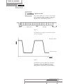
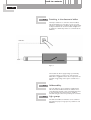
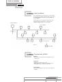
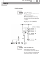
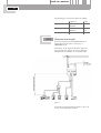
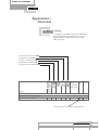
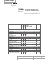
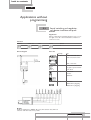
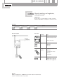
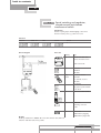
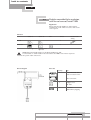
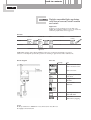
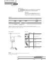
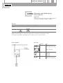
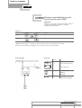
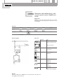
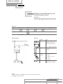
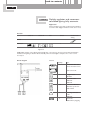
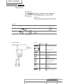
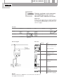
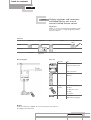
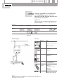
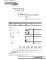
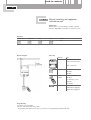
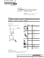
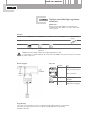
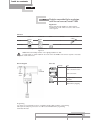
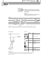
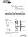
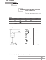
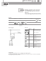
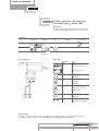
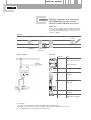
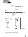
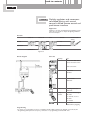
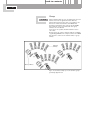
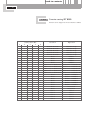
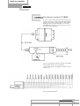
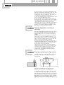
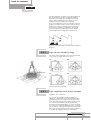
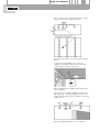
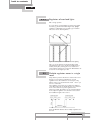
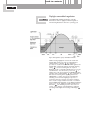
DALI SPECIFICATION GUIDE
Page 2/3
contents
1.
INTRODUCTION
2.
2.1.
2.2.
2.3.
2.4.
2.5.
2.6.
2.7.
2.8.
DALI - THE STANDARD
Industry standard
Light control
Digital control
Switching in the electronic ballast
Addressability
Light groups
Simple installation
Characteristics of DALI
Page
6
6
6
6
7
8
8
8
9
9
Page
5.
5.1.
5.2.
5.3.
5.4.
5.5.
3.
3.1.
3.2.
2.1
2.2
DALI SYSTEM
System description
Switch and sensor lines
Structure
Sensor line lengths to suit practical
needs
2.3 Maximum line lengths
4.
APPLICATIONS / OVERVIEW
4.1. Routing
4.2. Overview:Which function with which
sensors, no programming
4.3. Overview:Which function with which
sensors, with programming
4.4. Explanation of symbols
10
10
10
11
5.6.
5.7.
11
12
13
13
5.8.
5.9.
5.10.
14
15
16
5.11.
5.12.
5.13.
5.14.
5.15.
5.16.
APPLICATIONS WITHOUT
PROGRAMMING
Manual switching and regulation, pushbutton interface and push-button
Manual switching and regulation,
infrared control
Manual switching and regulation,
infrared control, push-button
interface and switch
Daylight-controlled light regulation,
automatic
Daylight-controlled light regulation,
with manual control, switch 230V
Daylight-controlled light regulation,
with manual control, switch module
and switch
Daylight-controlled light regulation,
with infrared remote control
Movement-controlled lighting,
fully automatic
Movement-controlled lighting, with
manual control, switch 230V
Movement-controlled lighting, with
manual control, switch module and
switch
Movement-controlled lighting, with
infrared remote control
Daylight regulation and movementcontrolled lighting, fully automatic
Daylight regulation and movementcontrolled lighting, switch 230V
Daylight regulation and movementcontrolled lighting, with manual
control, switch module and switch
Daylight regulation and movementcontrolled lighting, with manual
control, infrared remote control
Daylight regulation and movementcontrolled lighting, with manual
control, infrared remote control and
push-button interface
17
17
18
19
20
21
22
23
24
25
26
27
28
29
30
31
32
contents
Page
Page
6.
6.1.
6.2.
6.3.
6.4.
6.5.
6.6.
6.7.
6.8.
6.9.
6.10.
6.11.
6.12.
6.13.
6.14.
APPLICATIONS WITH
PROGRAMMING
Manual switching and regulation, pushbutton interface and push-button
Manual switching and regulation,
infrared control
Manual switching and regulation,
infrared control, push-button
interface and switch
Daylight-controlled light regulation,
automatic
Daylight-controlled light regulation,
with manual control, switch 230V
Daylight-controlled light regulation,
with manual control, switch module
and switch
Daylight-controlled light regulation,
with infrared remote control
Movement-controlled lighting, with
manual
control, switch module and switch
Movement-controlled lighting, with
infrared remote control
Daylight regulation and movementcontrolled lighting, fully automatic
Daylight regulation and movementcontrolled lighting, switch 230V
Daylight regulation and movementcontrolled lighting, with manual
control, switch module and switch
Daylight regulation and movementcontrolled lighting, with manual
control, infrared remote control
Daylight regulation and movementcontrolled lighting, with manual
control, infrared remote control and
push-button interface
7.
33
33
34
35
36
37
38
39
40
PROGRAMMING THE
TRIOS DALI
7.1. Defining terms
1.1. Luminaire group
1.2. IR channel
1.3. PRESET
1.4. Group
7.2. Allocating addresses and assigning
them to a luminaire group
7.2.1. Addressing with IRT 1090
2.2. Addressing with IRT 8050
7.3. Dimming channels and defining
PRESETS
3.1. Remote control IRC 2130
3.2. Group setting IRC 2130
3.3. Wall-mounted remote control
IRT 8050
3.4. Group setting IRT 8050
3.5. Function setting IRT 8050
3.6. Push-button interface LCU 8020
7.4. TRIOS activation/deactivation
behaviour
47
47
47
47
47
48
49
49
50
51
51
52
53
53
54
55
56
41
8.
42
43
44
45
46
NOTES ON DAYLIGHTCONTROLLED LIGHT
REGULATION
8.1. Difference between "control" and
"regulation"
8.2. Principle of the light regulation circuit
8.3. Daylight-dependent switching or
dimming?
8.4. Tips for positioning the light sensor
4.1 Light sensor recording range
4.2 Light regulation with lateral windows
4.3 Regulation of overhead lights
8.5. Multiple regulation zones in a single
room
8.6. Daylight-controlled regulation
6.1. Master / slave programming
6.2. Setting the required value
9.
PRODUCT OVERVIEW
57
57
57
58
58
59
59
61
61
62
63
63
65
Page 4/5
back to contents
1.
Introdu c t i o n
2.
DALI - the standard
2.1
This documentation shows the technical possibilities of
the DALI system for specific applications.
It provides a detailed account of the numerous functions
offered depending on the system's sensor configuration.
The new standard of the DALI protocol (Digital
Addressable Lighting Interface) defines digital
communication between electronic ballasts and control
units.When defining the standard, a firm option was
taken not to develop a complex building control system
with maximised functional capabilities, but to create
instead a simple system with clearly defined structures.
DALI is not designed for a complex bus system, but
rather for intelligent, high-performance light management
in a single room.These functions can of course be
integrated into a building management system by means
of suitable interfaces.
Industry standard
To ensure full compatibility between DALI components
from different manufacturers, the DALI protocol is being
standardised globally in accordance with IEC 929.
This will create the basis for marketing and using DALI
components worldwide without encountering vendorspecific, national, or technical incompatibilities.
This standard is supported by globally-active and
renowned companies.
2.2
Light control
Since the DALI protocol has been designed for rooms
requiring professional light management, the following
functions have been defined:
Switching on / off Individual DALI electronic ballasts,
groups or all electronic ballasts in a
single system can be switched
on / off.
Dimming
The dimmable electronic DALI ballast
is equipped with a technical facility for
dimming the lamp current
logarithmically from 100% to 0.1% in
125 dimming steps (in practice, the
lower dimming level is set at 3% so as
to ensure that the lamp service life is
not compromised).
Light scenes
Up to 16 light scenes can be
programmed and retrieved in a single
DALI system.
Status display
The DALI protocol can also be used
to display and / or retrieve statuses of
the electronic ballast or lamp.
back to contents
2.
2.3.
Digital control
The electronic ballasts are connected to the controller
via two wires. Data packets consisting of 19 bits enable
the controller to communicate with the electronic
ballasts at a rate of 1200 bauds per second.
Start
Data byte
Address byte
Stop bits
Figure 1
The DALI line has a voltage of 16 V, with the tolerances
shown in the diagram.
16V (9.5 bis 22.5V)
V
0V (-6.5 bis 6.5V)
µs
Figure 2
The maximum current in a DALI system is limited to
250 mA in accordance with IEC 929.The current
consumption per electronic ballast is set at 2mA.
Giving maximum of 125 ballasts in a DALI installation.
Page 6/7
back to contents
2.
2.4.
Switching in the electronic ballast
The lamp is switched on / off in the electronic ballast.
This means that there is no longer need to use power
switches to interrupt the circuit.The 230 V supply voltage
is always available at the electronic ballast and light can
be switched or dimmed by means of a command via the
DALI line.
DALI line
230 V
Figure 3
The fact that the 230 V supply voltage is permanently
connected results in a power loss in each electronic
ballast.This is negligible, however, when compared to the
potential energy savings of the system considered as a
whole.
2.5.
Addressability
Up to 64 addresses can be assigned in a DALI system.
This means that 64 different electronic ballasts can be
controlled independently of each other. Addressing must
be performed after the system has been installed.
The addressing procedure is depended by the controller.
2.6.
Light groups
The addressed ballasts or luminaires can be combined
into light groups. Up to 16 groups are possible for each
DALI line.
back to contents
2.
2.7.
Simple installation
No special wiring such as twisted pairs or special cables
are required for installing a DALI line.Twin control wires
in existing installations can also be used as DALI lines.
‚Free installation‘
A DALI system can be installed as shown in the next
drawing, though it is important to ensure that the
maximum voltage drop does not exceed 2V.
DALI Controller
Free installation
DA
Max. 300m and
2V voltage drop
Figure 4
DALI ballast
2.8.
Characteristics of DALI
Planning
• DALI allows subsequent functional adaptation by the
control units
Installation
• Existing 5-pole cables can be used
• DALI means fewer control units and therefore less
wiring; this in turn means lower total costs.
Programming
• The programming feature offers new opportunities for
installers.
Page 8/9
back to contents
3.
DALI system
3.1.
System description
TRIOS DALI is a room lighting controller. It can be used
for the following functions:
• Daylight-controlled light regulation
• Movement-controlled switching
• Manual dimming via switches or IR remote control
These functions can be set by means of the IRT 1090
remote programming control, used in conjunction with an
appropriate sensor. Up to 5 independent light groups can
be programmed.
The TRIOS DALI controller is accommodated in a
surface-mounted housing to which up to 20 electronic
DALI ballasts can be connected via the DALI line.
The system power of the individual DALI ballasts and
groups of ballasts can be disregarded.
Figure 5
3.2.
Switch and sensor lines
Switches are to be connected using conventional
installation material for extra-low voltages
(e.g. U 72 1x4x0.5). Pre-connectorised cable material is
available for sensors and is described in detail below.
If longer cables need to be installed or tubes are used, a
cable of type U 72 1x4x0.5 can be employed. If long cable
runs are needed it is advisable to use shielded cable.
back to contents
3.
Structure
3.2.1
AWG26
FCC 6p
RJ-12 (6p/6c)
“western plug”
Pin
Colour
Function
1
white
+12V
Supply voltage for light- and movement sensor
2
black
0V
Ground
3
red
+5V
4
green
5
yellow
IR sensor, push-button interface
6
blue
Movement sensor
Supply voltage forIR sensor
Light sensor
Figure 6: Structure of the sensor line
3.2.2
Sensor line lengths to suit
practical needs
Sensor lines suitable for longer distances can be created
by plugging together pre-connectorised cables.
Extension cable f/m
e.g. LCC 8012, LCC 8013
Interlink cable m/m
e.g. LCC 8011, LCC 8014
Figure 7: The required cable length is obtained by adding
pre-connectorised extension cables.
Page 10/11
back to contents
3.
The following pre-connectorised cables are available:
Designation
Plug/plug
Plug/socket
Branching connector
3.2.3
Length
LCC 8011
1m
LCC 8014
5m
LCC 8012
5m
LCC 8013
20 m
LCC 8024
3f/1m
Maximum line lengths
Connection between sensor and TRIOS DALI 30 m
Total length of all sensor lines connected to a
TRIOS DALI 125 m
Performance can be impaired if these line lengths are
exceeded. If greater distances need to be spanned in
individual cases, it is advisable to use shielded cables.
Figure 8
For details about the push-button interface, refer to the
section " 7.3.6. Push-button interface".
back to contents
4.
Applications /
Overview
4.1.
Routing
The diagram below facilitates the precise identification of
the functional requirements which must be met by a
lighting installation and the layout of the necessary
DALI components
Is a movement sensor used? YES
Is a light sensor used? YES
Is a remote control used? YES
Is regulation via switches? YES
Is a switch used for switching? YES
Number of
Page Section
individual
light groups
O/I
Sensors
230V
DALI solutions
Manual switching and regulation
Switch module and switch
x
1
16
5.1
This page provides a description of the application.
Page 12/13
back to contents
4.
4.2.
Overview:Which function with
which sensors, no programming
DALI supports different modes of operation, depending
on the application.The TRIOS unit recognises which
sensors are connected and automatically adapts to these.
The following table provides an overview of these
functionalities and the related sensor combination.
No programming is required for these applications.
The parameters can only be adjusted on the sensors.
Number of
Page Section
individual light
groups
O/I
Sensors
230V
DALI solutions without programming
Manual switching and regulation
Switch module and switch
x
Infrared remote control
1
17
5.1
x
1
18
5.2
x
1
19
5.3
x
1
20
5.4
x
1
21
5.5
Infrared remote control, switch module
and switch
x
Daylight-controlled light regulation
Automatic
With manual control, switch 230V
x
With manual control, switch module
and switch
x
With infrared remote control
x
x
1
22
5.6
x
1
23
5.7
x
1
24
5.8
x
1
25
5.9
Movement-controlled switching
Fully automatic
With manual control, switch 230V
x
With manual control, switch module
and switch
x
With infrared remote control
x
1
26
5.10
x
1
27
5.11
x
x
1
28
5.12
x
x
1
29
5.13
x
Daylight-controlled and movement-controlled switching together
Fully automatic
With manual control, switch 230V
x
With manual control, switch module
and switch
x
With infrared remote control
x
x
1
30
5.14
x
x
x
1
31
5.15
x
x
x
1
32
5.16
With manual control, infrared remote
control, switch module and switch
x
back to contents
4.
4.3.
Overview:Which function with
which sensors, with programming
DALI supports different modes of operation, depending
on the application.The TRIOS unit recognises which
sensors are connected and automatically adapts to these.
The following table provides an overview of these
functionalities and the related sensor combination.
Number of
Page Section
individual light
groups
O/I
Sensors
230V
DALI solutions with programming
Manual switching and regulation
Switch module
x
Infrared remote control
1-5
33
6.1
x
1-5
34
6.2
x
1-5
35
6.3
x
2
36
6.4
x
2
37
6.5
x
2
38
6.6
x
2
39
6.7
x
1-5
40
6.8
x
1-5
41
6.9
x
x
1-5
42
6.10
x
x
1-5
43
6.11
Infrared remote control, switch module
and switch
x
Daylight-controlled regulation
Fully automatic
With manual control, switch 230V
x
With manual control, switch module
and switch
x
With infrared remote control
x
Movement-controlled switching
With manual control, switch module and
switch
x
With infrared remote control
x
Daylight-controlled and movement-controlled switching together
Fully automatic
With manual control, switch 230V
x
With manual control, switch module
and switch
x
With infrared remote control
x
x
1-5
44
6.12
x
x
x
1-5
45
6.13
x
x
x
1-5
46
6.14
With manual control, infrared remote
control, switch module and switch
x
Page 14/15
back to contents
4.
4.4.
Explanation of symbols
Switch 230V
IR receiver
Movement sensor
Light sensor
Switch module
By hand
Absent
Bright
Present
Dark
IR remote control
Medium brightness
The examples in sections 5 and 6 contain symbols for a brief
description of the relevant control and regulation pattern.
Manual control
Switch 230V
Switching and dimming using a push-button panel + RC5 interface
Switching and dimming by IR remote control
Daylight-controlled light regulation
Switches on if the daylight falls below the required value
Artificial light is adjusted in line with daylight conditions
Switches off if the level of daylight is more than 1.5 x the required value for longer than 15 minutes
Setting the required value for daylight-controlled light regulation using:
RC5 interface + push button panel
IR remote control
Light sensor adjustment
Movement-controlled light
Switches on if movement is recorded
Switches off if no movement is recorded; switch-off can be delayed for up to 45 minutes
back to contents
5.
Applications without
programming
5.1.
Manual switching and regulation,
push-button interface and pushbutton
Application
Choice of dimming and switching functions and / or up to
four light scenes via conventional switches, suitable for
conference rooms.
Function
Switch on
Switch off
Dim
Scenes
Circuit
1
Circuit diagram
Parts list
Quantity
1
Type
TRIOS DALI LRC 1620
Surface-mounted version
DALI control unit
Any pulse-operated switch
from others
1
Push-button
Interface
LCU 8020
1
Sensor line
LCC 8014 5m plug/plug
LCC 8011 1m plug/plug
Default
IR: Group A, Channel 1 / PRESET: P1= 100%, P2= 50%, P3= 25%, P4= 10%
Switch on with 230V switch not possible.
Page 16/17
back to contents
5.
5.2.
Manual switching and regulation,
infrared control
Application
Rooms where no vertical wiring is possible, especially
attractive with flexible room plans or conference rooms.
Function
Switch on
Switch off
Dim
Scenes
Circuit
1
Circuit diagram
Parts list
Quantity
1
Type
TRIOS DALI LRC 1620
Surface-mounted version
DALI control unit
1
IR sensor
IRR 8124
IRR 8125
Any
number
IR remote control
IRC 2130
- 5 channels, 4 scenes
IRT 8050
- 2 switches
1
Sensor line
LCC 8014 5m plug/plug
LCC 8012 5m plug/sckt.
Default
IR: Group A, Channel 1 / PRESET: P1= 100%, P2= 50%, P3= 25%, P4= 10%
Switch on with 230V switch not possible.
back to contents
5.
5.3.
Manual switching and regulation,
infrared control, push-button
interface and switch
Application
Rooms requiring simple, flexible lighting control from
fixed and mobile points; e g conference rooms
Function
Switch on
Switch off
Dim
Scenes
Circuit
1
Circuit diagram
Parts list
Quantity
1
Type
TRIOS DALI LRC 1620
Surface-mounted version
DALI control unit
1
IR sensor
IRR 8124
IRR 2125
Any
number
IR remote control
IRC 2130
- 5 channels, 4 scenes
IRT 8050
- 2 switches
Any pulse-operated switch
from others
1
LCU 8020 switch module
1
LCC 8024
Branching connector
1m/3f
2
Sensor line
LCC 8014 5m plug/plug
Default
IR: Group A, Channel 1 / PRESET: P1= 100%, P2= 50%, P3= 25%, P4= 10%
Switch on with 230V switch not possible.
LCC 8012 5m plug/socket
Page 18/19
back to contents
5.
5.4.
Daylight-controlled light regulation,
automatic
Application
Power savings through daylight use, with automatic
reactivation. Is used in offices or factories with central
control systems.
Function
Switch on
Switch off
Dim
Circuit
Nominal value
setting
Manual
Automatic
1
at min light level
at 150% of ref.
light level
TRIOS DALI automatically switches on the lighting installation at dusk.
A central switch, or switch installed in the circuit before the TRIOS control unit is required to
deactivate the system outside office hours.
Circuit diagram
Parts list
Quantity
1
Type
TRIOS DALI LRC 1620
Surface-mounted version
DALI control unit
Central
Switch
1
Daylight sensor
LRL 8101
1
Sensor line
LCC 8014 5m plug/plug
back to contents
5.
5.5.
Daylight-controlled light regulation,
with manual control, switch 230V
Application
Energy saving through daylight use, with automatic
reactivation. Is used in offices or factories with central
control systems.
Function
Switch on
Switch off
Dim
Circuit
Nominal value
setting
Manual
1
Automatic
1
at min light level
at 150% of ref.
light level
TRIOS DALI automatically switches on the lighting installation at dusk.
A central switch, or switch installed in the circuit before the TRIOS control unit is required to
deactivate the system outside office hours.
Circuit diagram
Parts list
Quantity
1
Type
TRIOS DALI LRC 1620
Surface-mounted version
DALI control unit
1
Daylight sensor
LRL 8101
1
Sensor line
LCC 8014 5m plug/plug
Page 20/21
back to contents
5.
5.6.
Daylight-controlled light regulation,
with manual control, switch module
and switch
Application
Conference rooms, auditoria and rooms with some
daylight, where lighting conditions need to be matched to
momentary requirements and energy saved.
Function
Switch on
Switch off
Dim
Circuit
Nominal value
setting
Manual
1
Automatic
1
at PRESET 1
at 150% of ref.
light level
TRIOS DALI switches off the lighting installation when there is sufficient natural light. It can only be
switched on manually.This prevents the system from switching on again unnoticed after staff have left.
Circuit diagram
Parts list
Quantity
1
Type
TRIOS DALI LRC 1620
Surface-mounted version
DALI control unit
Any pulse-operated switch
from others
1
Daylight sensor
LRL 8101
1
Switch module
LCU 8020
1
Branching connector
1m/3f LCC 8024
2
Sensor line
LCC 8014 5m plug/plug
Default
IR: Group A, Channel 1 / PRESET: P1= 100%, P2= 50%, P3= 25%, P4= 10%
No daylight control: P2, P3, P4
back to contents
5.
5.7.
Daylight-controlled light regulation,
with infrared remote control
Application
This solution provides flexible lighting and the ability to
regulate dependent on daylight conditions, and is
therefore ideal for modern offices. It is also suitable for
renovations, since no wall switches need to be installed.
Function
Switch on
Switch off
Dim
Circuit
Nominal value
setting
Manual
1
Automatic
1
at PRESET 1
at 150% of ref.
light level
TRIOS DALI switches off the lighting installation when there is sufficient natural light. It can only be
switched on manually.This prevents the system from switching on again unnoticed after staff have left. Convenient
IR remote control for easy setting of required values.
Circuit diagram
Parts list
Quantity
1
Type
TRIOS DALI LRC 1620
Surface-mounted version
DALI control unit
1
Multisensor
LRI 8133
Any
number
IR remote control, e.g.:
IRC 2130
- 5 channels, 4 scenes
IRT 8050
- 2 switches
1
Sensor line
LCC 8014 5m plug/plug
Default
IR: Group A, Channel 1 / PRESET: P1= 100%, P2= 50%, P3= 25%, P4= 10%
No daylight control: P2, P3, P4
Page 22/23
back to contents
5.
5.8.
Movement-controlled lighting,
fully automatic
Application
Conference rooms and corridors where light is switched
on and off automatically according to occupancy.
Function
Switch on
Switch off
Circuit
Manual
1
Automatic
1
at PRESET 1
TRIOS switches the light on / off after the last detected movement.The interval between the last
movement and deactivation of the light can be set on the sensor for up to 45 minutes.
Circuit diagram
Parts list
Quantity
Type
TRIOS DALI LRC 1620
1
Surface-mounted version
DALI control unit
1
Movement sensor
LRM 8112
LRM 8115
1
Sensor line
LCC 8014 5m plug/plug
back to contents
5.
5.9.
Movement-controlled lighting, with
manual control, switch 230V
Application
Conference rooms and corridors where light is switched
on and off automatically according to occupancy.
Possibility of manual override.
Function
Switch on
Manual
+
Automatic
Switch off
Circuit
1
1
at PRESET 1
TRIOS switches the light on / off after the last detected movement.The interval between the last
movement and deactivation of the light can be set on the sensor for up to 45 minutes.
Circuit diagram
Parts list
Quantity
Type
TRIOS DALI LRC 1620
1
Surface-mounted version
DALI control unit
1
Movement sensor
LRM 8112
LRM 8115
1
Sensor line
LCC 8014 5m plug/plug
Page 24/25
back to contents
5.
5.10.
Movement-controlled lighting, with
manual control, switch module and
switch
Application
Exhibition rooms where different ambiences are required.
The lighting is automatically switched off when the room
is unoccupied.
Function
Switch on
Switch off
Dim
Scenes
Circuit
Manual
1
Automatic
1
at PRESET
Circuit diagram
Parts list
Quantity
1
Type
TRIOS DALI LRC 1620
Surface-mounted version
DALI control unit
Any pulse-operated switch
from others
1
Switch module
LCU 8020
1
Movement sensor
LRM 8112
LRM 8115
1
Branching connector
1m/3f
LCC 8024
1
Sensor line
LCC 8014 5m plug/plug
Default
IR: Group A, Channel 1 / PRESET: P1= 100%, P2= 50%, P3= 25%, P4= 10%
No daylight control: P2, P3, P4
back to contents
5.
5.11.
Movement-controlled lighting, with
infrared remote control
Application
Modern workplaces.The light is adjusted automatically in
accordance with daylight conditions and the user's needs.
Function
Switch on
Switch off
Dim
Scenes
Circuit
Manual
1
Automatic
1
at PRESET
Circuit diagram
Parts list
Quantity
1
Type
TRIOS DALI LRC 1620
Surface-mounted version
DALI control unit
1
Multisensor
LRI 8133
Any
number
IR remote control
IRC 2130
- 5 channels, 4 scenes
IRT 8050
- 2 switches
1
Sensor line
LCC 8014 5m plug/plug
Default
IR: Group A, Channel 1 / PRESET: P1= 100%, P2= 50%, P3= 25%, P4= 10%
No daylight control: P2, P3, P4
Page 26/27
back to contents
5.
5.12.
Daylight regulation and movementcontrolled lighting, fully automatic
Application
Modern workplaces.The light is adjusted automatically in
accordance with daylight conditions and the user's needs.
Function
Switch on
Switch off
Dim
Circuit
Nominal value
setting
Manual
Automatic
1
at PRESET 1
at 150% of ref.
light level
TRIOS DALI switches on the lighting automatically when a movement is detected provided that natural light is
insufficient.The lighting is switched off automatically when the natural light is adequate and / or the room is
unoccupied.
Circuit diagram
Parts list
Quantity
1
Type
TRIOS DALI LRC 1620
Surface-mounted version
DALI control unit
1
Daylight sensor
LRL 8101
1
Movement sensor
LRM 8112
LRM 8115
or 1
Multisensor LRI 8133
Alternative product for
LRM and LRL
1
Branching connector
1m/3f
LCC 8024
1
Sensor line
LCC 8014 5m plug/plug
back to contents
5.
5.13.
Daylight regulation and movementcontrolled lighting, switch 230V
Application
Modern workplaces.The light is adjusted automatically in
accordance with daylight conditions and the user's needs.
Function
Switch on
Switch off
Dim
Circuit
Nominal value
setting
Manual
+
Automatic
1
at PRESET 1
Circuit diagram
at 150% of ref.
light level
Parts list
Quantity
1
Type
TRIOS DALI LRC 1620
Surface-mounted version
DALI control unit
1
Daylight sensor
LRL 8101
1
Movement sensor
LRM 8112
LRM 8115
or 1
Multisensor LRI 8133
Alternative product for
LRM and LRL
1
Branching connector
1m/3f
LCC 8024
1
Sensor line
LCC 8014 5m plug/plug
Page 28/29
back to contents
5.
5.14.
Daylight regulation and movementcontrolled lighting, with manual
control, switch module and switch
Application
Rooms where the lighting must be regulated manually in
accordance with daylight conditions and the light needs
to be switched off automatically, e.g. conference rooms
with some daylight.
Function
Switch on
Switch off
Dim
Circuit
Nominal value
setting
Manual
1
Automatic
1
at PRESET 1
Circuit diagram
at 150% of ref.
light level
Parts list
Quantity
1
Type
TRIOS DALI LRC 1620
Surface-mounted version
DALI control unit
Any pulse-operated
switch from others
1
Multisensor
LRI 8133
1
Switch module
LCU 8020
1
Branching connector
1m/3f
LCC 8024
2
Sensor line
LCC 8014 5m plug/plug
Default
IR: Group A, Channel 1 / PRESET: P1= 100%, P2= 50%, P3= 25%, P4= 10%
No daylight control: P2, P3, P4
back to contents
5.
5.15.
Daylight regulation and movementcontrolled lighting, with manual
control, infrared remote control
Application
Suitable for modern and multi-functional lighting systems
where the user wishes to adjust the lighting conditions
from his workplace.
Function
Switch on
Switch off
Dim
Circuit
Nominal value
setting
Manual
1
Automatic
1
at PRESET 1
Circuit diagram
at 150% of ref.
light level
Parts list
Quantity
1
Type
TRIOS DALI LRC 1620
Surface-mounted version
DALI control unit
1
Multisensor
LRI 8133
Any
number
IR remote control, e.g.:
IRC 2130
- 5 channels, 4 scenes
IRT 8050
- 2 switches
1
Sensor line
LCC 8014 5m plug/plug
Default
IR: Group A, Channel 1 / PRESET: P1= 100%, P2= 50%, P3= 25%, P4= 10%
No daylight control: P2, P3, P4
Page 30/31
back to contents
5.
5.16.
Daylight regulation and movementcontrolled lighting, with manual
control, infrared remote control and
push-button interface
Application
Suitable for modern and multi-functional lighting systems
where the user wishes to adjust the lighting conditions
from his workplace.
Function
Switch on
Switch off
Dim
Circuit
Nominal value
setting
Manual
1
Automatic
1
at PRESET 1
Circuit diagram
at 150% of ref.
light level
Parts list
Quantity
1
Type
TRIOS DALI LRC 1620
Surface-mounted version
DALI control unit
1
Multisensor
LRI 8133
1
Switch module
LCU 8020
1
Branching connector
1m/3f LCC 8024
Any
number
IR remote control, e.g.:
IRC 2130
- 5 channels, 4 scenes
IRT 8050
- 2 switches
1
Sensor line
LCC 8014 5m plug/plug
Default
IR: Group A, Channel 1 / PRESET: P1= 100%, P2= 50%, P3= 25%, P4= 10%
No daylight control: P2, P3, P4
back to contents
6.
Applications with
programming
6.1.
Manual switching and regulation,
push-button interface and pushbutton
Application
Selecting dimming, switching and / or up to four light
scenes via conventional switches: suitable for conference
rooms.
Function
Switch on
Switch off
Dim
Scenes
Circuits
2-5
Circuit diagram
Parts list
Quantity
1
Type
TRIOS DALI LRC 1620
Surface-mounted version
DALI control unit
Any pulse-operated switch
1
Push-button
Interface
LCU 8020
1
Sensor line
LCC 8014 5m plug/plug
LCC 8011 1m plug/plug
Programming
See chapter on programming – Programming will require the temporary connection of an
IR receiver IRR 8125 and a programming transmitter IRT 1090
Page 32/33
back to contents
6.
6.2.
Manual switching and regulation,
infrared control
Application
Rooms where no vertical wiring is possible, especially
attractive with flexible room plans or conference rooms.
Function
Switch on
Switch off
Dim
Scenes
Circuits
2-5
Circuit diagram
Parts list
Quantity
1
Type
TRIOS DALI LRC 1620
Surface-mounted version
DALI control unit
1
IR sensor
IRR 8124
IRR 8125
Any
number
IR remote control
IRC 2130
- 5 channels, 4 scenes
IRT 8050
- 2 switches
1
Sensor line
LCC 8014 5m plug/plug
LCC 8012 5m plug/sckt.
Programming
See chapter on programming
Switch on with 230V switch not possible.
– Programming will require the temporary connection of a programming transmitter IRT 1090
back to contents
6.
6.3.
Manual switching and regulation,
infrared control, push-button
interface and switch
Application
In conference rooms where the light needs to be
location-specific (entrance) and flexible.
Function
Switch on
Switch off
Dim
Scenes
Circuits
2-5
Circuit diagram
Parts list
Quantity
1
Type
TRIOS DALI LRC 1620
Surface-mounted version
DALI control unit
1
IR sensor
IRR 8124
IRR 2125
Any
number
IR remote control
IRC 2130
- 5 channels, 4 scenes
IRT 8050
- 2 switches
Any pulse-operated switch
1
LCU 8020 switch module
1
LCC 8024
Branching connector
2
Sensor line
LCC 8014 5m plug/plug
LCC 8012 5m plug/socket
Programming
See chapter on programming
Switch on with 230V switch not possible. – Programming will require the
temporary connection of a programming transmitter IRT 1090
Page 34/35
back to contents
6.
6.4.
Daylight-controlled light regulation,
automatic
Application
Energy saving through daylight use, with automatic
reactivation. Is used in offices or factories with central
control systems.
Function
Switch on
Switch off
Dim
Circuits
Nominal value
setting
Manual
1
Automatic
2
at min light level
at 150% of ref.
light level
TRIOS DALI automatically switches on the lighting installation at dusk.
A central switch, or switch installed in the circuit before the TRIOS control unit is required to deactivate
the system outside office hours.
Circuit diagram
Parts list
Quantity
1
Type
TRIOS DALI LRC 1620
Surface-mounted version
DALI control unit
Central
switch
1
Daylight sensor
LRL 8101
1
Sensor line
LCC 8014 5m plug/plug
Programming
See chapter on programming and notes on daylight-controlled light regulation – Programming
will require the temporary connection of an IR receiver IRR 8125 and a programming
transmitter IRT 1090
back to contents
6.
6.5.
Daylight-controlled light regulation,
with manual control, switch 230V
Application
Energy saving through daylight use, with automatic
reactivation. Is used in offices or factories with central
control systems.
Function
Switch on
Switch off
Dim
Circuits
Nominal value
setting
Manual
1
Automatic
2
at min light level
at 150% of ref.
light level
TRIOS DALI automatically switches on the lighting installation at dusk.
A central switch, or switch installed in the circuit before the TRIOS control unit is required to deactivate
the system outside office hours
Circuit diagram
Parts list
Quantity
1
Type
TRIOS DALI LRC 1620
Surface-mounted version
DALI control unit
Central
switch
1
Daylight sensor
LRL 8101
1
Sensor line
LCC 8014 5m plug/plug
Programming
See chapter on programming and notes on daylight-controlled light regulation – Programming
will require the temporary connection of an IR receiver IRR 8125 and a programming
transmitter IRT 1090
Page 36/37
back to contents
6.
6.6.
Daylight-controlled light regulation,
with manual control, switch module
and switch
Application
Conference rooms, auditoria and rooms with some
daylight, where lighting conditions need to be matched to
momentary requirements and energy saved.
Function
Switch on
Switch off
Dim
Circuits
Nominal value
setting
Manual
2-5
Automatic
2
at PRESET 1
at 150% of ref.
light level
TRIOS DALI switches off the lighting installation when there is sufficient natural light. It can only be
switched on manually.This prevents the system from switching on again unnoticed after staff have left.
Circuit diagram
Parts list
Quantity
1
Type
TRIOS DALI LRC 1620
Surface-mounted version
DALI control unit
Any pulse-operated switch
1
Daylight sensor
LRL 8101
1
Switch module
LCU 8020
1
Branching connector
LCC 8024
2
Sensor line
LCC 8014 5m plug/plug
Programming
See chapter on programming and notes on daylight-controlled light regulation – Programming
will require the temporary connection of an IR receiver IRR 8125 and a programming
transmitter IRT 1090
back to contents
6.
6.7.
Daylight-controlled light regulation,
with infrared remote control
Application
This solution provides flexible lighting and the ability to
regulate dependent on daylight conditions, and is
therefore ideal for modern offices. It is also suitable for
renovations, since no switches need to be installed.
Function
Switch on
Switch off
Dim
Circuits
Nominal value
setting
Manual
2-5
Automatic
2
at PRESET 1
at 150% of ref.
light level
TRIOS DALI switches off the lighting installation when there is sufficient natural light. It can only be switched on
manually.This prevents the system from switching on again unnoticed after staff have left.
Circuit diagram
Parts list
Quantity
1
Type
TRIOS DALI LRC 1620
Surface-mounted version
DALI control unit
1
Multisensor
LRI 8133
Any
number
IR remote control, e.g.:
IRC 2130
- 5 channels, 4 scenes
IRT 8050
- 2 switches
1
Sensor line
LCC 8014 5m plug/plug
Programming
See chapter on programming and notes on daylight-controlled light regulation
No daylight control: P2, P3, P4 – Programming will require the temporary connection of a
programming transmitter IRT 1090
Page 38/39
back to contents
6.
6.8.
Movement-controlled lighting, with
manual control, switch module and
switch
Application
Exhibition rooms where different ambiences are required.
The lighting is automatically switched off when the room
is unoccupied.
Function
Switch on
Switch off
Dim
Scenes
Circuits
Manual
2-5
Automatic
2-5
at PRESET
Circuit diagram
Parts list
Quantity
1
Type
TRIOS DALI LRC 1620
Surface-mounted version
DALI control unit
Any pulse-operated switch
1
Switch module
LCU 8020
1
Movement sensor
LRM 8112
LRM 8115
1
Branching connector
LCC 8024
1
Sensor line
LCC 8014 5m plug/plug
Programming
See chapter on programming and notes on daylight-controlled light regulation. No daylight
control: P2, P3, P4 – Programming will require the temporary connection of an IR receiver IRR
8125 and a programming transmitter IRT 1090
back to contents
6.
6.9.
Movement-controlled lighting, with
infrared remote control
Application
Modern workplaces.The light is adjusted automatically in
accordance with daylight conditions and the user's needs.
Function
Switch on
Switch off
Dim
Scenes
Circuits
Manual
2-5
Automatic
2-5
at PRESET
Circuit diagram
Parts list
Quantity
1
Type
TRIOS DALI LRC 1620
Surface-mounted version
DALI control unit
1
Multisensor
LRI 8133
Any
number
IR remote control
IRC 2130
- 5 channels, 4 scenes
IRT 8050
- 2 switches
1
Sensor line
LCC 8014 5m plug/plug
Programming
See chapter on programming – Programming will require the programming transmitter IRT 1090
Page 40/41
back to contents
6.
6.10.
Daylight regulation and movementcontrolled lighting, fully automatic
Application
Modern workplaces.The light is adjusted automatically in
accordance with daylight conditions and the user's needs.
Function
Switch on
Switch off
Dim
Circuits
Nominal value
setting
Manual
1
Automatic
2
at PRESET 1
at 150% of ref.
light level
Circuit diagram
Parts list
Quantity
1
Type
TRIOS DALI LRC 1620
Surface-mounted version
DALI control unit
1
Daylight sensor
LRL 8101
1
Movement sensor
LRM 8112
LRM 8115
or 1
Multisensor LRI 8133
Alternative product for
LRM and LRL
1
Branching connector
LCC 8024
1
Sensor line
LCC 8014 5m plug/plug
Programming
See chapter on programming and notes on daylight-controlled light regulation
No daylight control: P2, P3, P4 – Programming will require the temporary connection of an IR receiver IRR 8125
and a programming transmitter IRT 1090
back to contents
6.
6.11.
Daylight regulation and movementcontrolled lighting, switch 230V
Application
Modern workplaces.The light is adjusted automatically in
accordance with daylight conditions and the user's needs.
Function
Switch on
Switch off
Dim
Circuits
Nominal value
setting
Manual
1
+
Automatic
2
at PRESET 1
at 150% of ref.
light level
Circuit diagram
Parts list
Quantity
1
Type
TRIOS DALI LRC 1620
Surface-mounted version
DALI control unit
1
Daylight sensor
LRL 8101
1
Movement sensor
LRM 8112
LRM 8115
or 1
Multisensor LRI 8133
Alternative product for
LRM and LRL
1
Branching connector
LCC 8024
1
Sensor line
LCC 8014 5m plug/plug
Programming
See chapter on programming and notes on daylight-controlled light regulation – Programming will require the
temporary connection of an IR receiver IRR 8125 and a programming transmitter IRT 1090
Page 42/43
back to contents
6.
6.12.
Daylight regulation and movementcontrolled lighting, with manual
control, switch module and switch
Application
Rooms where the lighting must be regulated manually in
accordance with daylight conditions and the light needs
to be switched off automatically, e.g. conference rooms
with some daylight
Function
Switch on
Switch off
Dim
Circuits
Nominal value
setting
Manual
1-5
Automatic
2
at PRESET 1
at 150% of ref.
light level
Circuit diagram
Parts list
Quantity
1
Type
TRIOS DALI LRC 1620
Surface-mounted version
DALI control unit
Any pulse-operated switch
1
Multisensor
LRI 8133
1
Switch module
LCU 8020
1
Branching connector
LCC 8024
2
Sensor line
LCC 8014 5m plug/plug
Programming
See chapter on programming and notes on daylight-controlled light regulation
No daylight control: P2, P3, P4 – Programming will require the temporary connection of an IR
receiver IRR 8125 and a programming transmitter IRT 1090
back to contents
6.
6.13.
Daylight regulation and movementcontrolled lighting, with manual
control, infrared remote control
Application
Suitable for modern and multi-functional lighting systems
where the user wishes to adjust the lighting conditions
from his workplace.
Function
Switch on
Switch off
Dim
Circuits
Nominal value
setting
Manual
1-5
Automatic
2
at PRESET 1
at 150% of ref.
light level
Circuit diagram
Parts list
Quantity
1
Type
TRIOS DALI LRC 1620
Surface-mounted version
DALI control unit
1
Multisensor
LRI 8133
Any
number
IR remote control, e.g.:
IRC 2130
- 5 channels, 4 scenes
IRT 8050
- 2 switches
1
Sensor line
LCC 8014 5m plug/plug
Programming
See chapter on programming and notes on daylight-controlled light regulation
No daylight control: P2, P3, P4 – Programming will require the temporary connection of a
programming transmitter IRT 1090
Page 44/45
back to contents
6.
6.14.
Daylight regulation and movementcontrolled lighting, with manual
control, infrared remote control and
push-button interface
Application
Suitable for modern and multi-functional lighting systems
where the user wishes to adjust the lighting conditions
from his workplace.
Function
Switch on
Switch off
Dim
Circuits
Nominal value
setting
Manual
1-5
Automatic
2
at PRESET 1
at 150% of ref.
light level
Circuit diagram
Parts list
Quantity
1
Type
TRIOS DALI LRC 1620
Surface-mounted version
DALI control unit
1
Multisensor
LRI 8133
1
Switch module
LCU 8020
1
Branching connector
LCC 8024
Any
number
IR remote control, e.g.:
IRC 2130
- 5 channels, 4 scenes
IRT 8050
- 2 switches
1
Sensor line
LCC 8014 5m plug/plug
Programming
See chapter on programming and notes on daylight-controlled light regulation. No daylight control: P2, P3, P4
– Programming will require the temporary connection of a programming transmitter IRT 1090
back to contents
7.
Programming the
TRIOS DALI
7.1.
7.1.1.
Defining terms
Luminaire group
A luminaire group consists of one or more luminaires
containing a DALI ballast.The addressing operation
assigns an address to each DALI ballast or luminaire.
Different luminaires can be combined into a single
luminaire group (see Addressing the luminaires).
7.1.2.
IR channel
If one or more luminaires are combined into a luminaire
group, this, in the case of TRIOS DALI, is known as a
channel.There are five IR channels, numbered from
"1" to "5". Each TRIOS DALI can switch and dim up to
five channels individually.
Figure 9: Five channels, each can be dimmed individually
7.1.3.
PRESET
When the use of a room is changed, it is possible to
change the lighting to match the new requirements.
Work at a desk involving the use of a monitor for
example, requires lighting quite different to that needed
for a conference or for a presentation with a beamer.
Individual ambiences, each tuned to a particular activity,
can be created by dimming each channel and the required
setting can be recorded as a "PRESET" or light scene
(see Section 7.3).The personal light scenes can be
instantly recalled by pressing the appropriate button of
the ir transmitter. Up to four presets are possible.
Figure 10: Four presets
Page 46/47
back to contents
7.
Group
7.1.4.
Infrared signals radiate in space in all directions.To avoid
interference between signals which have different,
independent functions in the same room addresses are
allocated to infrared transmitters and TRIOS units.
An infrared transmitter thus controls only the TRIOS
units within its own group. Units with other group
addresses are not affected.
Seven groups are possible, identified with the letters
"A" to "G".
Each group has ist own five channels, with the possibility
of generating PRESETS.The complete address of a TRIOS
unit therefore consists of the channel address + group
address.
Channel
address
Group address
Figure 11: Schematic example of a room with three groups
operated by different users
back to contents
7.
7.2.
Allocating addresses and assigning
them to a luminaire group
Addressing can be carried out after installation has been
completed.This requires an IR receiver (IRR 8125, IRR
8124) and the IRT 1090 programming remote control or
the IR wall switch IRT 8050.When programming is
carried out, the luminaire or luminaire group gives a
confirmation by lighting up and then dimming.
7.2.1.
Addressing with IRT 1090
The five steps
1 Press Mode 5 button
All lamps light up to 100%
Red LED on TRIOS flashes
Lamps dim one after another to 3%
One lamp lights up and dims
2 Channel selection
Acknowledgement: lamp dims, next lamp lights up and
dims up/down
3 Step 2 is repeated
until all lamps have been addressed
4 Wait 10 seconds
5 Select group
All lamps light up and dim
It is important to ensure
that the distance between
the IR receiver and the
IRT 1090 programming
remote control does not
exceed 2m.
Group
address
Signal transmission
between the IRT 1090 and
TRIOS can be tested by
pressing the "P1" and "Off"
buttons in succession.
If the TRIOS does not
respond, the cause may be
one of the following:
Channel
address
Mode
Figure 12
Distance between TRIOS and IRT 1090 too great
Decrease distance and target more precisely
The group address of the IRT 1090 has been changed
Press buttons "C" and "D" simultaneously for more
than two seconds.The left-hand red LED flashes
Press button "B" as often as necessary until the three
red LEDs at the top right light simultaeneously.
Press buttons "C" and "D" again simultaneously for
more than two seconds
Page 48/49
back to contents
7.
7.2.2.
Addressing with IRT 8050
The IRT 8050 can send many different commands, but as
it has only two buttons, the internal dip switches must be
changed.
The five steps:
1 Press Mode 5 button
- Open remote control device
- All selector switches to ON
- Close remote control device
- Press button
All lamps go to 100%
Red LED on TRIOS flashes
Lamps dim in succession to 3%
One lamp goes off
2 Channel selection
- Open remote control device
- Selector switch to position Channel 1 to 5
- Close remote control device
- Press button
Acknowledgement: Lamp lights up and dims.
The next lamp goes to 100%
3 Repeat step 2
until all lamps have been addressed
4 Wait 10 seconds
5 Select group
All lamps light up and dim
Figure 13
Figure 14
Selector switch assignment
Switch 'ON'
1
2
3
•
•
•
•
•
•
•
•
•
•
•
•
•
•
•
•
•
•
4
5
6
7
•
•
•
•
•
•
•
Right switch
Channel 1 off / down
Channel 1 on / up
Channel 2 off / down
Channel 2 on / up
Channel 3 off / down
Channel 3 on / up
Channel 4 off / down
Channel 4 on / up
Channel 5 off / down
Channel 5 on / up
Mode 5
Mode 5
8
•
•
Left switch
•
back to contents
7.
7.3.
7.3.1.
Dimming channels and defining
PRESETS
Remote control IRC 2130
Light scenarios can comprise up to five individually
dimmed channels with the TRIOS system. Once chosen,
a combination of dimming values can be saved as a
PRESET and recalled by simply pressing a button.
The PRESET values are recorded in the individual TRIOS,
not in the remote control device. Factory settings of the
TRIOS DALI are P1=100%, P2=50%, P3=25%, P4=10%.
The IR remote control IRC 2130 is a tool for controlling
channels and presets.
Figure 15: Function keys of the IR remote control IRC 2130
The functionality of the five pairs of channel buttons
depends on the duration for which they are pressed:
• Left: short duration = "Off", long duration = dimmer
• Right: short duration = "On", long duration = brighter
The steps mentioned in Figure 15 can be used to define a
new preset or to modify an existing one:
• Create the required lighting scenario by dimming the
channels individually (1)
• Press "Save" (record) button (2)
• Press "Preset" button (3)
The lighting scenario has now been recorded under this
PRESET button and can be called up again at any time.
The group address of the IRC 2130 infrared transmitter
is set using the group selector switch in the battery
compartment. "All groups" is used, for example, to
implement a central function.
Page 50/51
back to contents
7.
7.3.2.
Group setting IRC 2130
Group assignments are carried out on the underside of
the remote control device.This device can be used by up
to seven users in one room to set their specific lighting
requirements in their individual zones without influencing
other surrounding zones.
Figure 16: Group selector switch in the IRC 2130 infrared
remote control
When delivery an IR transmitter is defaulted with the
address "A", while a TRIOS unit has the default setting
"A1".
back to contents
7.
7.3.3.
Wall-mounted remote control
IRT 8050
Buttons I and II on the wall-mounted remote control can
be adapted to the required functions, e.g. to retrieve
presets or to dim lighting.
The remote control is ready for programming as soon as
batteries have been inserted:
• Set the first selector switch to the appropriate number
(1-3)
7.3.4.
Group setting IRT 8050
Switch position 'ON'
1
2
Group addresses
3
A
•
•
B
•
•
•
•
•
•
C
D
•
•
•
•
E
F
G
ALL
Figure 17
Page 52/53
back to contents
7.
7.3.5.
Function setting IRT 8050
Functions can be assigned to the two switches as follows:
Switch position 'ON'
4
5
6
7
•
•
•
•
•
•
•
•
•
•
•
•
•
•
•
•
•
•
•
•
•
•
•
•
•
•
•
•
•
•
•
•
•
•
•
•
•
•
•
•
•
•
•
•
•
•
•
•
•
•
•
•
•
Left switch
Right switch
Channel 1 off / down
Channel 1 on / up
Channel 2 off / down
Channel 2 on / up
Channel 3 off / down
Channel 3 on / up
Channel 4 off / down
Channel 4 on / up
Channel 5 off / down
Channel 5 on / up
All off
PRESET 1
All off
PRESET 2
All off
PRESET 3
8
•
•
•
•
•
•
•
•
•
•
•
•
All off
PRESET 4
Channel 1 on ⇔ Channel 1 off
Channel 2 on ⇔ Channel 2 off
Channel 2 on ⇔ Channel 2 off
Channel 3 on ⇔ Channel 3 off
Channel 3 on ⇔ Channel 3 off
Channel 4 on ⇔ Channel 4 off
Channel 4 on ⇔ Channel 4 off
Channel 5 on ⇔ Channel 5 off
Channel 5 on ⇔ Channel 5 off
Channel 1 on ⇔ Channel 1 off
All off
PRESET 1 ⇔ PRESET 2
All off
PRESET 1 ⇔ PRESET 3
All off
PRESET 1 ⇔ PRESET 4
All off
PRESET 4 ⇔ PRESET 3
All off
PRESET 4 ⇔ PRESET 2
All off
PRESET 4 ⇔ PRESET 1
All off
P1, P2, P3, P4
All off
P4, P3, P2, P1
Mode 1
Mode 1
Mode 2
Mode 2
Mode 3
Mode 3
Mode 4
Mode 4
Mode 5
Mode 5
back to contents
7.
7.3.6.
Push-button interface LCU 8020
A remote control and the switch module have the same
functions.The switch module and commercially available
switches can be used to retrieve light moods or dim the
lighting.The switch module LCU 8020 is connected to
the TRIOS DALI controller in the same way as a sensor
via an RJ 12 connecting cable.
Figure 18: Connecting the push-button interface to the TRIOS
The individual switches can be assigned the
corresponding functions by fitting the switches as shown
in Figure 19.
Figure 19: Switch combinations
Page 54/55
back to contents
7.
7.4.
TRIOS activation/deactivation
behaviour
It is possible to change the activation and deactivation
behaviour of the TRIOS as follows:
Mode selection
Function
Remote control
Mode 1 + Mode 2
Auto ON is switched off
mode 1
Auto OFF level is 0%
mode 3
Mode 2 + Mode 3
Auto ON is switched on
mode 2
Auto OFF level is 0%
mode 3
Mode 1 + Mode 4
Auto ON is switched off
mode 1
Auto OFF level is 3%
mode 4
Mode 2 + Mode 4
Auto ON is switched on
mode 2
Auto OFF level is 3%
mode 4
This feature can be used to create applications where
automatic switch-on or switch-off to 0% is not required.
Example: Security lighting in corridors or hospitals.
Programming is carried out using the IRT 1090 or IRT
8050 remote control units. Each change of mode
generates a confirmation.The luminaires dim and light up.
back to contents
8.
Notes on daylightcontrolled light
regulation
8.1.
Difference between "control" and
"regulation"
Unlike a control unit, a regulator ensures that the
required illuminance will be maintained.
A control unit executes a command without recording
the result.
Example:Window blind control
A regulator records the result of the operation and can
correct it if necessary.
Example: Radiator thermostat
The process of checking the result of such an operation
and comparing it with the required value is called
"feedback" and distinguishes a regulator from a control
unit.
8.2.
Principle of the light regulation
circuit
Daylight and artificial light combine to provide illuminance
at user level, i.e. generally speaking, on the working plane
such as a desk or workbench.The process of automatic
regulation of the output (luminous flux) of the lighting
installation according to the varying contribution of
natural light is destined to maintain constant the
predefined level of illuminance on the working plane.
This is achieved by the system making a continuous
comparison between the required illuminance and the
total illuminance resulting from the natural and artificial
light reflected from the working plane and received by a
sensor.
Figure 20: Operating principle of an automatic light regulation
system
Page 56/57
back to contents
8.
In order to measure correctly the total illuminance, the
light sensor must be placed directly above the user level
(cf. Section 6.3). Any other positioning of the sensor
would result in erroneous feedback to the system and
consequently in unsatisfactory functioning.
Section 6.8.1 explains how the required illuminance level
can be set with the TRIOS DALI system.
Correct operation of the regulating circuit can only be
ensured if all the components in the circuit, i.e. regulator
(e.g.TRIOS), ballast, lamp and sensor, are tuned to each
other. Ideally they should be supplied by the same
manufacturer, since, despite the extensive standardisation
of the technology used, tolerances and differences in
detail can occur between different manufacturers, and
this in turn can result in functional problems.
8.3.
Daylight-dependent switching or
dimming?
Automatic daylight-linked regulating systems save energy
and costs by gradually dimming and extinguishing the
lighting installation as soon as adequate natural light is
available.
Medical research and practical experience prove that a
sudden drop of 10% in the illuminance level in a room
has a disruptive effect on people present. If the artificial
light in an office is suddenly switched off everyone will
look up and concentration will be disturbed.
Progressive dimming prior to extinction, balanced by
increasing natural light, makes the switching-off operation
virtually imperceptible as this occurs at a level much
lower than the critical 10% threshold.
The importance of the quality of an artificial lighting
installation should be seen as being proportional to the
acuteness of the visual tasks to be carried out in the
room. In offices an installation with high-frequency
operation and a daylight-linked dimming function is
therefore recommended.
8.4.
Tips for positioning the light sensor
The light sensor must be directed towards a working
plane which offers good and consistent reflection
characteristics.
Figure 21: Sensor fitted above the working plane; the
illustration shows a room with a window at the side.
As explained in Section 6.2, the sensor must be fitted
above the illuminated working plane, so that it receives
light reflected form that plane. Since the sensor measures
the total illuminance resulting from natural and artificial
light, influences such as obstructions in front of windows,
shadows caused by window blinds and ageing of the
lighting system itself are automatically taken into account.
back to contents
8.
No direct light must reach the sensor. Direct light from
the window must be avoided as must light radiated
upwards by, for example free standing or suspended
direct / indirect luminaires. Sensors are in fact best
installed at the same height as the luminaires.
Since the working plane serves as a reflecting surface, it
should be used as a reference for the entire room and
should not be subject to fluctuations in its reflection
factor. It is, for example, not advisable to fit the light
sensor directly above a light-coloured floor which is
occasionally used for storing dark coloured goods.
Figure 22: Sensor fitted above areas with consistent reflective
properties.
8.4.1.
Light sensor recording range
The design of the latest light sensors has been matched
to the needs of modern office work spaces.
Figure 23: Light sensor sensitivity.
8.4.2.
Light regulation with lateral windows
Regulation close to windows
As a general rule, daylight-controlled regulation is
effective to a depth in the room which corresponds to
approximately twice the height of the window. In office
areas with usual dimensions, this distanced will be some
3 to 5 m. At points further from the windows, the
penetration of natural light will be too low to be useful
as a component of the overall illuminance for working. In
case of doubt, a comparative measurement between the
indoor and outdoor illuminance will help. If the different
is less than 1%, regulation will not be worthwhile.
Page 58/59
back to contents
8.
Figure 24 shows the recommended position for a light
sensor in a room with a window at the side.
Figure 24: Sensor position in a room with window located at
the side
To prevent direct light falling on the sensor, the
installation aids moulded on the sensor components
should be aligned as shown in Figure 25.
Figure 25: Alignment of the installation aids moulded on the
sensor components.
There may never be sufficient daylight in the shadow of
large cupboards or machinery. Such zones must not be
used as reflecting work planes for installation and setting
of light sensors.
Figure 26: No daylight regulation over areas in shadow.
back to contents
8.
8.4.3.
Regulation of overhead lights
Full coverage possible
In rooms where overhead lights are arranged at regular
intervals (e.g. sheds with double-ridged roof), daylight
regulation of all luminaries is generally a good solution.
The sensor can be fitted anywhere.
Figure 27: Sensor position in a hall with overhead lighting
Here, too, areas which are in shadow should remain
unregulated, and the sensor should be installed above a
surface (work plane) offering the most constant and
representative reflection properties.The LRL 8101/20 can
be used for room heights up to 8m.
8.5.
Multiple regulation zones in a single
room
Safety distance prevents interference between the zones
A large room or hall is best divided into several
regulation zones.The subdivision can be based on the
division of the room itself, otherwise 100m2 - 200 m2 per
zone is a useful value.
The regulation zones must not be allowed to influence
each other. Light sensors should therefore be positioned
in the centre of their respective regulation zone
wherever possible.The distance to the nearest luminaire
in the adjacent regulation zone should not be less than
the installation height of the sensors.
Figure 28: Minimum distances where multiple regulation zones
are used
Page 60/61
back to contents
8.
Daylight-controlled regulation
8.6.
The TRIOS DALI multifunctional light controller
LRC 1620 is ideal for daylight-controlled regulation.
The following illustration shows the operating cycle.
Figure 29: Regulation cycle for dimmable luminaires
With increasing daylight the total of the natural and
artificial light matches the value of total illuminance
calibrated in the controller.
The calibration
procedure is described below.TRIOS DALI regulates the
artificial light continuously until the minimum dimming
setting
is reached, ensuring that the required
illuminance level is constantly maintained. As soon as the
total illuminance exceeds 1.5x the preset level
,a
waiting time of 15 min. is initiated, and TRIOS DALI then
switches off the artificial lighting
.This combination of
limit value and waiting time is preprogrammed into
TRIOS DALI to obviate unnecessary and disturbing
switching on and off of the lighting in response to
momentary and minor changes of weather conditions.
If the circuit is designed with an automatic re-activation
feature TRIOS DALI will switch on the lighting installation
again as soon as the daylight level falls below the fixed
threshold
.The dimming sequence then ensues in
reverse order ensuring constant illuminance balancing
decreasing natural light and increasing artificial light
.
back to contents
8.
8.6.1.
Master / slave programming
Connection of a light sensor informs the TRIOS DALI
controller that daylight-linked regulation is required.
By assigning channels 1 and 2, it is possible to obtain a
'master / slave' circuit.The ‘master’ luminaires nearest the
window will automatically dim as daylight increases.
The ‘slave’ luminaires, installed further from the windows
where the daylight penetration is less, will also dim but
not to so low a level as the ‘master’ luminaires.When
adequate daylight is available the ‘master’ luminaires will
automatically switch off and the ‘slave’ luminaires will be
dimmed further. Maximum energy saving is achieved
whilst a balanced lighting level is constantly maintained
over the whole room.
Programming the master / slave circuit
Channel 1 on / off
Master / slave luminaires switch on or off
Channel 1 up / down
This function can be used to set the reference light level
of the master (regulation is switched off during this
process)
Channel 2 on / off
No function in this application
Channel 2 up / down
This function can be used to set the level of the slave
luminaire relative to the master luminaire.The level can
be set as identical, lower, or higher. Generally it will be
higher
8.6.2.
Setting the required value
Fast setting, can be changed at any time; using IR remote
control.
Preparations:
Obscure the windows. Measure the artificial light level
(illuminance) with a lux meter.
If it is not possible to exclude natural light, measure the
illuminance of the natural light on the working plane
below the light sensor with the artificial light switched
off. If the value lies above the required level of
illuminance, the measurements must be made again after
nightfall
With the artificial light switched on, measure the
illuminance on the working plane.
Setting:
If an IR remote control or RC5 Push button interface
+ switch is connected:
Set the required value by pressing the channel buttons
(light up / dim). Five seconds after the time the last
button is pressed,TRIOS DALI records the new
illuminance level set as the required level.This level can
also be recorded a PRESET: up to four different PRESET
levels can be recorded for push-button selection.
Page 62/63
back to contents
8.
Settings can be changed at any time; using a screwdriver.
Settings can also be carried out on the light sensor when
using dimmable systems, but this is a relatively
complicated operation compared to the processes
described above.
The red LED indicates the operating range of the sensor,
though this is not relevant for fine adjustment.
While the unit is adjusting, ensure that nothing obstructs
the detection area of the sensor.
If the LED does not light up, position the sensor over a
brighter surface.
Preparations:
Obscure the windows the artificial light level
(illuminance) with a lux meter.
If it is not possible to exclude natural light, measure the
illuminance of the natural light on the working plane
below the light sensor with the artificial light switched
off. If the value lies above the required level of
illuminance, the measurements must be made after
nightfall.
With the artificial light switched on, measure the
illuminance on the working plane.
Setting:
Lighting level too low:
Turn the screw in counter-clockwise direction until the
required level is obtained.
Lighting level too high:
Turn the screw in clockwise direction until the required
level is obtained.
Figure 30: Setting the required value by matching the
sensitivity of the LRL 8101 sensor using a size 0 screwdriver.
back to contents
9.
Product overview
LRC 1620 TRIOS DALI Room controller
EOC: 8711500 74751830
Philips no.: 9137 005 22403
6
3,5
158
175
Dimensions in mm
54
60
125
Description
Technical data
TRIOS DALI multifunctional light controller for local
room-based installation. Offers pre-defined functions
for the connection of movement detectors, infrared
receivers and/or a light sensor.TRIOS DALI is
specifically designed for DALI ballasts and energy
saving lighting solutions with dimmable light.
Environmental conditions
- Ambient temperature +5 to +55°C
Mains
- Uin: 230V ± 10% 50/60Hz
- Pdis.: 7W
- Lin: 40mA
- Pf: 0.75
DALI interface
- Max. 20 DALI ballsts
IRC 2130 Infrared hand-held transmitter
EOC: 8711500 74644330
Philips no.: 9137 005 21203
163
Dimensions in mm
70
23
Description
Technical data
Four-preset, hand-held/wall-mounted infrared remote
control transmitter for use with TRIOS DALI light
controllers. Incorporates programming and storage
capacity for four presets and five channels.
Environmental conditions
- Ambient temperature +5 to +55°C
Power supply
- 4 alkaline dry batteries, type LR03 1.5V
Transmission codes
- RC5
Weight
- 180g (with batteries)
Page 64/65
back to contents
9.
IRT 8050 Infrared transmitter for wall mounting
EOC: 8711500 74645030
Philips no.: 9137 005 21303
93
80
8
Dimensions in mm
8
28
80
Description
Technical data
Multipurpose infrared remote control transmitter for
wall mounting. Dedicated functions can be allocated
to the two push buttons on the front side.
Environmental conditions
- Ambient temperature +5 to +55°C
Power supply
- 4 alkaline dry batteries, type LR03 1.5V
Transmission codes
- RC5
Weight
- 115g (With batteries)
IRT 1090 Infrared programming transmitter
EOC: 8711500 74646730
Philips no.: 9137 005 21403
163
Dimensions in mm
70
23
Description
Technical data
Hand-held infrared remote control transmitter for
easy programming of TRIOS DALI controllers.
Environmental conditions
- Ambient temperature +5 to +55°C
Power supply
- 4 alkaline dry batteries, type LR03 1.5V
Transmission codes
- RC5
Weight
- 180g
back to contents
9.
LRI 8133 Multisensor
EOC: 8711500 74639930
Philips no.: 9137 005 20703
Dimensions in mm
∅ 70
8
Ø 113
Ø 116
Ø 99
6
33
28
60
Ø 95
Description
Technical data
Multisensor combining infrared receiver, movement
detector and light sensor for the remote and
automatic control of lighting systems.The three
sensors can be selected individually. A flanged ring for
recessed mounting and a plate for surface mounting
are supplied.
Environmental conditions
- Ambient temperature +5 to +55°C
Power supply
- 12 V ± 10 % 20mA
Electrical connections
- Telejack RJ 12
Weight
- 90g
LRM 8112 Movement detector
EOC: 8711500 74639930
Philips no.: 9137 005 20703
Dimensions in mm
∅ 70
8
Ø 113
Ø 99
Ø 116
33
28
60
Ø 95
Description
Technical data
Movement detector for the automatic control of
lighting systems. Provided with adjustable switch-off
delay times from 0 to 45 mins. A flanged ring for
recessed mounting and a plate for surface mounting
are supplied.
Movements are detected in an almost circular zone
of approx. 8m. diameter.
Environmental conditions
- Ambient temperature +5 to +55°C
Power supply
- 12 V ± 10 % 10mA
Electrical connections
- Telejack RJ 12
Weight
- 90g
Detection area
- ∅ 8m at a mounting height of 2.6 to 3m
Page 66/67
back to contents
9.
LRM 8115 Movement detector for wall mounting
EOC: 8711500 74641230
Philips no.: 9137 005 20903
66
Dimensions in mm
61.3
66
4.5
70
30
12
70
Description
Technical data
Wall-mounted movement detector for the automatic
control of lighting systems. Provided with adjustable
switch-off delay times from 0 to 35 mins., it detects
the slightest movement in e.g. a corridor 3m wide
and 25m long.The sensor has a built-in daylight
override function that increases the energy-saving
potential of the solution.
Environmental conditions
- Ambient temperature +5 to +55°C
Power supply
- 12 V ± 10 % 10mA
Electrical connections
- Telejack RJ 12
Detection area
- 25m x 3m width at a mounting height of 2.6 to 3m
LRL 8101 Light sensor
EOC: 8711500 74640530
Philips no.: 9137 005 20803
Dimensions in mm
8
∅ 70
Ø 113
Ø 116
Ø 99
33
28
60
Ø 95
Description
Technical data
Light sensor for automatic daylight regulation. A
flanged ring for recessed mounting and a plate for
surface mounting are supplied.
Environmental conditions
- Ambient temperature +5 to +55°C
Power supply
- 12 V ± 10 % 10mA
Electrical connections
- Telejack RJ 12
Weight
- 90g
Sensitivity
- 50 to 20 000 lux
back to contents
9.
IRR 8124 Infrared receiver
EOC: 8711500 74647530
Philips no.: 9137 005 20503
Dimensions in mm
∅ 70
Ø 113
8
Ø 99
60
Ø 116
33
28
Ø 95
Description
Technical data
Infrared receiver for the remote control of lighting
systems. A flanged ring for recessed mounting and a
plate for surface mounting are supplied.
Environmental conditions
- Ambient temperature +5 to +55°C
Power supply
- 5 V ± 10 % 3mA
Electrical connections
- Telejack RJ 12
Weight
- 90g
Sensitivity
- 30 square metres enclosed by 3 walls
IRR 8125 "Invisible" IR receiver
EOC: 8711500 74638230
Philips no.: 9137 005 20603
Dimensions in mm
4
2.5
26
5
9
1000
65
30
6
45
21
Description
Technical data
Infrared receiver for remote control lighting systems
with a standard connecting cable of 500 mm.
Environmental conditions
- Ambient temperature +5 to +55°C
Power supply
- 5 V ± 10 % 1mA
Electrical connections
- cable with Telejack RJ 12
Weight
- 30g
Sensitivity
- 30 square metres surrounded by 3 walls
Page 68/69
back to contents
9.
LCU 8020 Push-button interface
EOC: 8711500 74643630
Philips no.: 9137 005 21103
Dimensions in mm
28
40
148
159
Description
Technical data
Push-button interface. RC 5 code generator with
digital inputs for connection of push-buttons.
Intended for manual control of lighting controllers.
The unit is connected to the infrared remote control
input of the controller.
Environmental conditions
- Ambient temperature +5 to +55°C
Power supply
- 12V ± 10 % 5 mA
Electrical connections
- cable with Telejack RJ 12
Weight
- 77g
LCC 8011 Interlink cable 1m
EOC: 8711500 74649830
Philips no.: 9137 005 21703
Description
Interlink cable of 1 m length with modular plugs at
each end for interconnecton of TRIOS DALI light
controllers.
LCC 8012 Extension cable 5m
EOC: 8711500 74650430
Description
Extension cable of 5 m length with modular plug and
socket. Suitable as connection or extension lead
between sensors and controllers.
Philips no.: 9137 005 21803
back to contents
9.
LCC 8013 Extension cable 20m
EOC: 8711500 74651130
Philips no.: 9137 005 22003
Description
Sensor cable of 20 m length with modular plug and
socket. Suitable as connection or extension lead
between sensors and controllers.
LCC 8014 Sensor cable 5m
EOC: 8711500 74652830
Philips no.: 9137 005 20803
Description
Interlink cable of 1 m length with modular plug at
each end for interconnecton of TRIOS DALI light
controllers.
LCC 8024 3 Branching connector
EOC: 8711500 74653530
Philips no.: 9137 005 21103
Description
Branching connector with three modular sockets and
one modular plug for connection of a light sensor
and multiple infrared receivers and movement
detectors to one TRIOS DALI light controller input.
Page 70/71


![Overview DR120 Service manual [v00]](http://vs1.manualzilla.com/store/data/006012884_1-f54ceab96779dba42a616edbeea41727-150x150.png)