1
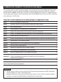
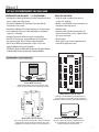
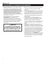
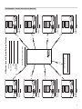
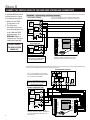
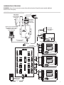
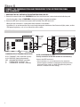
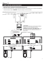
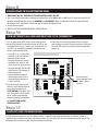
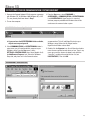
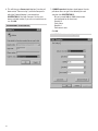
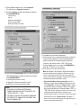
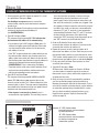
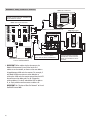
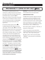
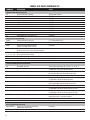
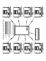
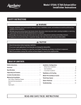
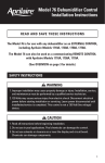
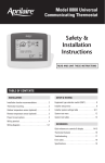
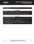
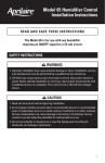
HVAC Automation
Communicating Thermostat
System Installation Manual
COMMUNICATING THERMOSTAT SYSTEM INSTALLATION MANUAL
This manual will guide the installer through the installation, wiring and checkout of an Aprilaire Model 8870 Communicating
Thermostat System. Instructions for the Aprilaire 8840 Series communicating thermostat system are found in a separate
document (Part No. 10004345). A portion of the command set is found in Appendix 2 in this manual. For a complete command
set with programming suggestions, see the programming manual (Part No. 10005756). Contact Research Products Corporation
for these documents at 888-782-8638.
THERE ARE 14 STEPS INVOLVED IN THE INSTALLATION OF A COMPLETE SYSTEM.
Step 1
GET ALL THE COMPONENTS YOU WILL NEED
1
Step 2
DISCONNECT POWER TO ALL HVAC EQUIPMENT AND/OR ZONE CONTROL PANELS
2
Step 3
RUN THE REQUIRED WIRES
3
Step 4
LOCATE AND MOUNT THE AUTOMATION SYSTEM COMPONENTS
4
Step 5
CONNECT THE CONTROL WIRES TO THE HVAC/ZONE SYSTEM AND THERMOSTATS
6
Step 6
CONNECT THE COMMUNICATION AND POWER WIRES TO THE DISTRIBUTION PANEL AND THERMOSTAT
8
Step 7
CONNECT MULTIPLE DISTRIBUTION PANELS
9
Step 8
CONNECT PROTOCOL ADAPTER TO THE DISTRIBUTION PANEL AND HOST COMPUTER OR AUTOMATION SYSTEM 10
Step 9
PROVIDE POWER TO THE DISTRIBUTION PANEL
11
Step 10
TURN ON POWER TO ALL HVAC EQUIPMENT AND TO THE THERMOSTATS
11
Step 11
CHECK-OUT HVAC SYSTEM OPERATION
11
Step 12
ADDRESS THE THERMOSTATS AND SET HIGHEST ADDRESS
12
Step 13
SETUP COMPUTER FOR COMMUNICATION SYSTEM CHECKOUT
13
Step 14
CHECK-OUT COMMUNICATIONS TO THE THERMOSTAT NETWORK
16
Appendix 1 SPECIAL CONSIDERATIONS FOR INSTALLING THE MODEL 8870 WITH THE 8840 SERIES
COMMUNICATING THERMOSTAT
17
Appendix 2 APRILAIRE COMMAND SET
19
EXTRA NETWORK INTERCONNECTION WORKSHEET
21
WARNING
1. 120 volts may cause serious injury from electrical shock. Disconnect electrical power to the HVAC system before
starting installation. This system is a low-voltage system.
2. Improper installation may cause serious injury from electrical shock. This system must be installed by a qualified
contractor in accordance with NEC Standards and applicable local and state codes.
© 2008 Research Products Corporation
Step1
GET ALL THE COMPONENTS YOU WILL NEED
COMPONENTS YOU WILL NEED… (see ILLUSTRATION 1)
• One Aprilaire® Model 8870 Communicating Thermostat for each
zone or single zone HVAC system
• One Aprilaire Model 8818 Distribution Panel per eight (8)
thermostats in the system
• One Aprilaire Model 8811 Protocol Adapter per 32 thermostats
• 4 to 8 conductor thermostat cable depending on equipment
stages (18 – 20 gauge)
• Category 5 communication wire (4-pair twisted cable)
• One 24V AC transformer, ungrounded per 8818 Distribution
Panel (part number 8027 or California approved 8029)
• RS-232 or RS-485 based automation system such as the
Aprilaire Model 8825 System Controller
• OPTIONAL: Aprilaire Model 8061 Temperature Support Module
or Model 8062 Temperature/Humidity Support Module
TOOLS YOU WILL NEED…
• Small flat head screwdriver for terminal
screws (1/8” wide tip)
• Medium size flat/phillips head screwdriver for
component mounting screws
• Volt/ohm meter
• Computer with available com port (RS-232)
and terminal emulator such as HyperTerminal
(for system checkout)
• Wire strippers
• Small level (use to mount components level,
required for appearance only)
A+ A- B+ B-
A
REF
OFF ON
B
ON OFF
PWR
OFF ON
R
C
PWR
A
A
ON OFF
OFF ON
ON OFF
OFF ON
B
B
PWR
PWR
C
C
FUSE
A+ A- B+ B- R
A+ A- B+ B- R
A
A
ON OFF
OFF ON
ON OFF
OFF ON
B
B
PWR
PWR
C
C
RS-422 Communicating Thermostat controls single
or multi-stage heat/cool or heat pump HVAC systems.
B
OFF ON
B- B+ A- A+
ON OFF
R
B
PWR
C
Model 8870 Thermostat
OFF ON
B- B+ A- A+
ON OFF
SPARE FUSE
A+ A- B+ B- R
A
A
B- B+ A- A+
C
C
PWR
R
A
ON OFF
B
R
A+ A- B+ B- R
A
B- B+ A- A+
B
ILLUSTRATION 1 – System Components
MAIN
PWR
24VAC
C
R
ON OFF
RS-485/422
DC +9V
Model 8818 Distribution Panel
Switches in the Distribution Panel allow power or
communications to be turned off at each individual
thermostat to make installation and troubleshooting easy.
TXD
RXD
POWER
RS-232
Model 8811 Protocol Adapter
Model 8061 and 8062 Support Modules
Use to convert RS-485 communication signal from Aprilaire
Communication System to RS-232 communication signal
readable by host computer. Supports up to 32 thermostats.
Up to four can be connected to a single thermostat
to sense temperature or relative humidity at a
location remote from the thermostat.
1
MODEL 8870 THERMOSTAT
The Model 8870 Thermostat is field configurable to operate
single and multi-stage separate heating and cooling
equipment (such as furnace and air conditioner or roof top
units), or single and multi-stage heat pump systems. A menu
driven set up, using the message center display of the
thermostat, can be used to configure many other features.
Network communication is non-isolated, full duplex RS-485
(RS-422). The ‘A’ terminals are the receive pair while the ‘B’
terminals are the transmit pair. This nomenclature uses the
computer or host as the reference, so transmit refers to the
lines on which the host transmits data to the thermostat
while receive refers to the lines on which the host receives
data from the thermostat. The baud rate is selectable
between 9600 and 19200. Up to 64 uniquely addressed
thermostats may reside on the same thermostat network.
MODEL 8818 DISTRIBUTION PANEL
The Distribution Panel is a switch controlled communication
bus that can be wired to eight (8) Aprilaire Model 8870
thermostats. This allows thermostat communication
(transmit, receive or both) to be turned on and off at one
convenient location which simplifies installation and trouble
shooting. Each thermostat station on the distribution panel
has an on/off switch for power. This allows isolation of any
one thermostat to simplify troubleshooting. Order one
Distribution Panel per eight thermostats.
MODEL 8061 AND MODEL 8062 SUPPORT MODULES
Support modules are used to either monitor or control
temperature or humidity at a location other than the
thermostat. They communicate with the thermostat using a
RS-485 protocol. Up to four support modules may be wired to
a thermostat, with each module able to support two sensors.
The Model 8061 has one onboard temperature sensor and
room for one offboard temperature sensor (sensor #1 &
sensor #2) while the Model 8062 has one onboard
temperature sensor (sensor #1) and one onboard humidity
sensor (sensor #2). All sensors can be configured as either a
control sensor (replaces thermostat temperature sensor as
control variable) or a monitor sensor (read only). An offboard
sensor such as a Model 8051 Flush Mount Sensor can
replace sensor #1 on the Model 8062 or both on the Model
8061. Each support module is addressed and each sensor
value can be accessed through thermostat commands. See
sensor literature for additional information.
FOR EASE OF INSTALLATION AND TROUBLE SHOOTING
DO THE FOLLOWING:
✔ Use Category-5 cable for all communication wiring.
✔ Check and recheck to ensure connection to the proper
terminals before powering up the thermostats. Use wire
color as a guide and be consistent.
✔ Use a Distribution Panel on all systems with more than
one zone. The trouble shooting benefits will outweigh the
cost of the Distribution Panel.
Step 2
DISCONNECT POWER TO ALL HVAC EQUIPMENT AND/OR ZONE CONTROL PANELS
• If the thermostats are wired to a zone control panel, there is generally one set of input terminals supplying power to the
thermostats and dampers. This must be disconnected.
• If the thermostats are wired directly to HVAC equipment, the power must be shut off at the equipment. This can generally be
accomplished by turning off the disconnect switch located near the equipment. If an obvious disconnect switch is
unavailable, you will need to turn the circuit off using the fuse or circuit breaker. Remove the fuse or shut down the circuit
breaker serving the equipment.
CAUTION
Failure to disconnect power could result in damage to the HVAC equipment or thermostats. Leave power disconnected
until all other electrical connections have been made and checked for accuracy.
2
Step 3
RUN THE REQUIRED WIRES (SEE ILLUSTRATION 2)
1. Run thermostat cable from each thermostat to the
appropriate HVAC system or zone control panel. Use 4
through 8-conductor thermostat cable depending on the
type of equipment and number of equipment stages. Run
one more wire than would be required if connecting to a
mechanical thermostat.
❖ If you are using remote temperature or humidity
support modules as part of your installation, now is the
time to run the additional wires for these items. A
separate Category 5 cable must be run from thermostat
to support module.
2. At the HVAC/zone control system, use a piece of tape to ✍
label the location of the thermostat on the cable as you go.
3. Run Category-5, 4-pair twisted cable (8-conductor) from
each thermostat to the Distribution Panel.
4. At the Distribution Panel, use a piece of tape to ✍ label
the location of the thermostat on the cable as you go.
5. Run Category-5 wire from the Distribution Panel to the
Protocol Adapter. If more than one Distribution Panel is
used, run Category-5 wire between each panel.
6. Run two-conductor thermostat cable from the
Model 8027 or 8029 Transformer to the Distribution Panel.
You can use Category-5 wire, but you must use one pair of
wires per terminal.
ILLUSTRATION 2 – Run Wire For System
Zone Dampers
Distribution Panel
Communicating Thermostat
Automation
System
RS-485/422
DC +9V
ZONE CONTROL SYSTEM
TXD
RXD
POWER
Zone Comfort Control Panel
HVAC System
RS-232
Protocol Adapter
(if needed)
Support Module
24VAC
C
R
DISTRIBUTION PANEL
24VAC
40VA
XFRMR
C R
Model 8051
Flush Mount Sensor
Straight through serial cable
provided with Protocol Adapter
Maximum Wiring Distances
From
To
Maximum Distance
Automation or
Computer System
Protocol Adapter
3 ft. Cable Provided with
Protocol Adapter
Protocol Adapter
Thermostat (this includes going
through the Distribution Panel)
4000 ft.
Thermostat
Support Module
1000 ft.
Support Module
Temperature Sensor Option
300 ft.
Category 5 (4 pair twisted)
communication wire
Thermostat cable
3
Step 4
LOCATE AND MOUNT THE AUTOMATION SYSTEM COMPONENTS
1. Thermostats and sensors are to be located according to
the installation instructions provided with the units. The
thermostat has four configuration dip switches on the
circuit board that must be set according to the equipment
the thermostat will be controlling. Sensors have six
configuration dip switches that must be properly set.
The installation manuals provided with the products detail
how the switches are to be set.
Review the Network Interconnection Worksheet
(ILLUSTRATION 3) which shows how all the
communication components are connected together
and ✍ write down the location of, or a name for, each
thermostat in the system. This will assist in the software
set-up. Additional copies are available in the back
of this manual.
✍ IMPORTANT!
THE FEW MINUTES SPENT WRITING DOWN
THE INFORMATION SUGGESTED IN THESE STEPS
WILL SAVE A TREMENDOUS AMOUNT OF TIME
DURING THE REST OF THE INSTALLATION.
4
2. Mount the zone control panel(s) if the HVAC system(s) is
zoned. Refer to the zone control panel installation
instructions.
3. The Aprilaire Distribution Panel must be mounted indoors
in an accessible location such as a closet or utility room.
All thermostats will be wired to the Distribution Panel, so
adequate workspace will be important. There are wire
access holes on the top, bottom, sides and back of the
Distribution Panel.
4. The Model 8811 Aprilaire Protocol Adapter must be
placed within three feet of the host computer or RS-232
port of the automation system. All the cables and
connectors needed to attach the Protocol Adapter to the
computer or automation system are included with the
adapter.
5. The Model 8027 or 8029 (California approved) Plug-in
Transformer is used to power the communication system.
The transformer is wired to the Distribution Panel. Locate
this transformer in the same space as the Distribution
Panel if possible. When using multiple distribution panels
and multiple transformers, make sure the polarity of the
individual transformer connections are consistent from
panel to panel. R from the transformer to R on the
distribution panel(s), etc. See DIAGRAM 5 for an example.
Even though the power source is AC, maintaining proper
polarity at each panel is very important for establishing
stable communications.
CAT-5
WIRE
DISTRIBUTION PANEL
LOCATION
ADDRESS
LOCATION
ADDRESS
TO DISTRIBUTION PANEL
ADDRESS
CAT-5
WIRE
LOCATION
ADDRESS
CAT-5
WIRE
CAT-5
WIRE
LOCATION
CAT-5
WIRE
ADDRESS
ADDRESS
LOCATION
LOCATION
CAT-5
WIRE
CAT-5
WIRE
ADDRESS
CAT-5
WIRE
DISTRIBUTION PANEL LOCATION / NAME
INSTALLING
CONTRACTOR:
LOCATION
ADDRESS
LOCATION
CAT-5
WIRE
DATE:
JOB LOCATION:
JOB TITLE:
Fill Out and Leave with System Software Package
ILLUSTRATION 3 – Network Interconnection Worksheet
5
Step 5
CONNECT THE CONTROL WIRES TO THE HVAC/ZONE SYSTEM AND THERMOSTATS
DIAGRAM 1 – Typical Heating / Cool Wiring Schematic
MULTI-STAGE FURNACE
USE 18-20 GA. THERMOSTAT CABLE. NUMBER OF CONDUCTORS
REQUIRED DEPENDS ON THE HVAC SYSTEM BEING CONTROLLED
Y2
2ND STAGE
COOL
2ND
STAGE
HEAT
W2
1ST STAGE
COOL
1ST
STAGE
HEAT
Y1
W1
FAN
RELAY
G
C
24
VAC
120
VAC
R
L1
L2
A qualified HVAC technician
should perform this step to
ensure proper termination.
1. Make sure the HVAC
system power is off.
2. The Thermostat
Installation Instructions
show wiring diagrams for
several different HVAC
equipment types. Use
DIAGRAMS 1 & 2 as a
reference only. Use color
coding where possible.
C
R
RSR
RSC
RSB
RSA
REF
MULTI-STAGE A/C
DO NOT TURN ON
THE HVAC SYSTEM
POWER YET!
2ND
STG
COOL
1ST
STG
COOL
Y2
RC
RH
R.V.-Cool (O)
R.V.-Cool
G
HUM W1
DEH Y1
W2
Y2
BB+
AA+
R.V.-Heat
R.V.-Heat (B)
Y1
C
REFER TO THE THERMOSTAT INSTALLATION SHEET FOR
INTERNAL SCHEMATIC, THERMOSTAT CHECK-OUT
PROCEDURES AND OTHER HVAC WIRING DETAILS
CAUTION!
ENSURE HVAC SYSTEM POWER
IS OFF BEFORE WIRING
DIAGRAM 2 – Typical Heat Pump Wiring Schematic
OUTDOOR HEAT PUMP UNIT
REV
VALVE
HEAT
R
SERVICE
L
C
W1
REV
VALVE
COOL
Y1
B
CAUTION!
ENSURE HVAC SYSTEM POWER
IS OFF BEFORE WIRING
Y2
2ND
STG
COMP.
DEFROST
1ST
STG
COMP.
O
USE 18-20 GA. THERMOSTAT CABLE. NUMBER
OF CONDUCTORS REQUIRED DEPENDS ON THE
HVAC SYSTEM BEING CONTROLLED
INDOOR BLOWER/HEAT UNIT
2ND
STAGE
AUX.
HEAT
FAN
RELAY
W2
1ST
STAGE
AUX.
HEAT
W1
G
C
120
VAC
R
L1
L2
24
VAC
REFER TO THE THERMOSTAT INSTALLATION
SHEET FOR INTERNAL SCHEMATIC, THERMOSTAT
CHECK-OUT PROCEDURES AND OTHER HVAC
WIRING DETAILS
6
C
R
RSR
RSC
RSB
RSA
REF
BB+
AA+
R.V.-Heat
.-Heat (B)
R.V
RC
RH
R.V.-Cool
R.V.-Cool (O)
G
HUM W1
DEH Y1
W2
Y2
COMMUNICATION SYSTEM WIRING
DIAGRAM 3 shows all communication system wiring with terminations. Steps 6 through 8 provide additional
detail for each wiring step.
DIAGRAM 3 – System Communication Wiring
9VDC 500mA
AC PLUG-IN
TRANSFORMER
(PROVIDED)
BLU/WHT
BLUE
ORANGE
DO NOT
CONNECT
ORG/WHT
B- B+ A+ A-
RS-485/422
BREAKOUT
ADAPTER
(PROVIDED)
A+
A-
B+
B-
RS-485/422
DC +9V
COMPUTER OR AUTOMATION
SYSTEM WITH RS232 SERIAL
COMMUNICATION PORT
(NOT PROVIDED)
2-WIRE TSTAT
CABLE
Model 8051
FLUSH MOUNT
SENSOR
TXD
RXD
RSR
RSC
RSB
RSA
T1
T2
T3
GRN
POWER
GRN/WHT
BRN
BRN/WHT
RS-232
T4
CAT-5
RS-232 3FT CABLE
(PROVIDED)
Model 8061 OR 8062 SUPPORT MODULE
CAT-5
GRN/WHT
BLU
BLU/WHT
ORG
ORG/WHT
GRN
GRN
Model 8818
DISTRIBUTION PANEL
GRN/WHT
BRN
BRN/WHT
A+ A- B+ B-
A
REF
B
B
ON OFF
PWR
OFF ON
CAT-5
ORG/WHT
ORG
OFF ON
ON OFF
OFF ON
B
B
PWR
PWR
R
ORG
BLU/WHT
ORG/WHT
BLU
BLU
ORG/WHT
BLU/WHT
ORG
GRN/WHT
ORG
OFF ON
ON OFF
B
B
ON OFF
OFF ON
PWR
PWR
BLU
GRN/WHT
BLU/WHT
GRN
C
GRN
GRN/WHT
24VAC
C
Model 8027
or 8029 PLUG-IN
TRANSFORMER
2-WIRE TSTAT
CABLE
R
C
R
RSR
RSC
RSB
RSA
REF
BB+
AA+
R.V.-Heat (B)
RC
RH
R.V.-Cool (O)
G
HUM W1
DEH Y1
W2
Y2
ORG/WHT
MAIN
PWR
24VAC
40VA
XFRMR
C R
R.V.-Cool (O)
G
HUM W1
DEH Y1
W2
Y2
Model 8870 THERMOSTAT
A
A
R
A+ A- B+ B- R
GRN
CAT-5
C
FUSE
A+ A- B+ B- R
ON OFF
GRN
C
C
A
A
BLU/WHT
GRN/WHT
B- B+ A- A+
PWR
BLU
R
PWR
B
OFF ON
GRN
C
ON OFF
GRN/WHT
B- B+ A- A+
B
ORG
ORG/WHT
CAT-5
OFF ON
SPARE FUSE
A+ A- B+ B- R
ON OFF
B- B+ A- A+
C
A
A
BB+
AA+
R.V.-Heat (B)
RC
RH
Model 8870 THERMOSTAT
C
PWR
B- B+ A- A+
OFF ON
BLU
R
A
ON OFF
B
BLU/WHT
C
A+ A- B+ B- R
A
C
R
RSR
RSC
RSB
RSA
REF
ON OFF
BLU/WHT
BLU
ORG/WHT
ORG
C
R
RSR
RSC
RSB
RSA
REF
BB+
AA+
R.V.-Heat (B)
RC
RH
R.V.-Cool (O)
G
HUM W1
DEH Y1
W2
Y2
Model 8870 THERMOSTAT
7
Step 6
CONNECT THE COMMUNICATION AND POWER WIRES TO THE DISTRIBUTION PANEL
AND THERMOSTAT
1. MAKE SURE THAT ALL SWITCHES IN THE DISTRIBUTION PANEL ARE OFF!
2. Connect the communication wires. DIAGRAM 4 shows how each thermostat is to be wired to the distribution panel.
• Use the wire colors shown in DIAGRAM 4 to help ensure proper, consistent connections.
3. Connect the REF terminal of each thermostat to the Distribution Panel REF terminals if:
• More than one transformer is used to power the thermostats in the network
• Installation is in an environment that has excessive electromagnetic interference from fluorescent lights, motors, or other
EMI generating devices, such as in an industrial or office setting
DIAGRAM 4 – Thermostat Communication Wiring
GRN/WHT
A+ A- B+ B-
See NOTE
ON REF
WIRE
A
REF
GRN/WHT
GRN
OFF ON
B
B
ON OFF
PWR
OFF ON
PWR
ORG
ORG/WHT
BLU
CAT-5
BLU/WHT
GRN/WHT
BLU/WHT
C
R
A
ON OFF
GRN
C
A+ A- B+ B- R
A
B- B+ A- A+
B
GRN/WHT
BLU
ORG/WHT
A+ A-
8
A
ON OFF
OFF ON
A- A+
ORG
A
C
R
RSR
RSC
RSB
RSA
REF
BB+
AA+
R.V.-Heat (B)
RC
RH
R.V.-Cool (O)
G
HUM W1
DEH Y1
W2
Y2
COMMUNICATION TERMINAL DEFINITIONS
NOTE ON REFERENCE WIRE
B+/BA+/AREF
R
C
Usually connection of the REF terminal is not necessary.
TRANSMIT (from automation system)
RECEIVE (from the thermostats)
GROUND REFERENCE (see Note)
THERMOSTAT VOLTAGE (hot)
THERMOSTAT VOLTAGE (common)
Connect the REF terminals if:
• Your installation is in an environment that has excessive
electromagnetic interference (experiencing interference from
fluorescent lights, motors, or other EMI generating devices,
found in an industrial or office setting).
Step 7
CONNECT MULTIPLE DISTRIBUTION PANELS
1. MAKE SURE THAT ALL SWITCHES IN THE DISTRIBUTION PANEL ARE OFF!
2. If more than one Distribution Panel is used in the thermostat network, the communication lines must be daisy-chained together.
• Use the wire colors shown in DIAGRAM 5 to help ensure proper, consistent connections.
DIAGRAM 5 – Multiple Distribution Panels
TXD
DC +9V
RS-485/422
A- A+ B+ BCAT-5
DO NOT
CONNECT
IF NECESSARY:
WHEN CONNECTING MULTIPLE DISTRIBUTION PANELS,
CONNECT THE “REF” TERMINALS FOR EACH
THERMOSTAT TO THE “REF” TERMINAL OF THE
RESPECTIVE DISTRIBUTION PANEL AND CONNECT THE
REF TERMINALS OF EACH DISTRIBUTION PANEL TO
EACH OTHER.
GRN/WHT
A
BLU
A+ A- B+ B-
A
REF
PWR
A
A
ON OFF
OFF ON
B
B
ON OFF
PWR
OFF ON
PWR
C
C
OFF ON
R
B
ON OFF
PWR
C
OFF ON
B
C
A
ON OFF
A+ A- B+ B- R
A+ A- B+ B- R
A
B
B- B+ A- A+
B
B- B+ A- A+
REF
R
A+ A- B+ B-
GRN/WHT
BLU/WHT
BLU/WHT
ORG
ORG
ORG/WHT
BLU
ORG/WHT
BLU
BLU/WHT
ORG
ORG/WHT
CAT-5
DISTRIBUTION PANEL #2
DISTRIBUTION PANEL #1
MAIN
PWR
MAIN
PWR
24VAC
24VAC
C
24VAC
40VA
XFRMR
C R
R
C
ON OFF
R
ON OFF
24VAC
40VA
XFRMR
C R
2-WIRE TSTAT
CABLE
2-WIRE TSTAT
CABLE
9
Step 8
CONNECT PROTOCOL ADAPTER TO THE DISTRIBUTION PANEL AND HOST COMPUTER
OR AUTOMATION SYSTEM
1. MAKE SURE THAT ALL SWITCHES IN THE DISTRIBUTION PANEL ARE OFF!
2. Use Category-5 wire to connect the main communication terminals on the Distribution Panel to the “Breakout Adapter” of
the protocol adapter (see DIAGRAM 6).
3. Connect the RS-232 cable from the protocol adapter to the computer or automation system. A 3 ft. RS-232 cable is provided.
Some computers use 25-pin connectors on serial ports, which requires a DB25 connector. A DB9 connector fits a 9-pin
port. DB9 to DB25 transitions are available at most computer retail stores.
4. Power up the Protocol Adapter with the plug-in transformer provided. The “Power” LED on the Protocol Adapter should
light up when power is applied.
DIAGRAM 6 – Protocol Adapter Wiring
CAT-5 NETWORK CABLE (NOT PROVIDED)
BLU/WHT
BLUE
ORANGE
ORG/WHT
9VDC 500mA
AC PLUG-IN
TRANSFORMER
(PROVIDED)
DO NOT
CONNECT
B- B+ A+ A-
A-
A+
B+
B-
RS-485/422 BREAKOUT
ADAPTER (PROVIDED)
A+ A- B+ B- REF REF
APRILAIRE MODEL 8818
DISTRIBUTION PANEL
OR MODEL 8870
COMMUNICATING
THERMOSTAT
RS-485/422
DC +9V
COMPUTER OR AUTOMATION
SYSTEM WITH RS232 SERIAL
COMMUNICATION PORT
(NOT PROVIDED)
RS-485/422
DC +9V
PIN #1
TXD
RXD
POWER
DB9 RS-485 /422 CONNECTOR PIN-OUT
PIN #
RS-232
RS-232 3FT CABLE
(PROVIDED)
10
1
2
3
4
5
6
7
8
9
A- A+ B- B+
RS-485/422
GND NC +9V NC NC
Tx- Tx+ Rx- Rx+
Step 9
PROVIDE POWER TO THE DISTRIBUTION PANEL
1. MAKE SURE THAT ALL SWITCHES IN THE DISTRIBUTION PANEL ARE OFF!
2. Use a 2-wire thermostat cable to connect the load terminals of the Model 8027 or 8029 Plug-in Transformer to the 24V AC
terminals of the Distribution Panel (see DIAGRAM 3 and DIAGRAM 5). Make sure R of the Transformer goes to R of the
Distribution Panel, and C of the Transformer goes to C of the Distribution Panel..
3. Plug-in the transformer.
4. NO LEDs ON THE DISTRIBUTION PANEL SHOULD BE ON.
Step 10
TURN ON POWER TO ALL HVAC EQUIPMENT AND TO THE THERMOSTATS
A+ A- B+ B- R
R
C
C
B- B+ A- A+
FUSE
C
C
R
A+ A- B+ B- R
B- B+ A- A+
4. One by one, turn on only the power switches (not the
1. Turn on power to the HVAC and/or zone control systems.
communication switches) for each thermostat. Verify that
2. Go to the Distribution Panel and verify that no LEDs on the
the green LED comes on and that the thermostat display
Distribution Panel are on. If none are on, proceed to # 3. If
powers up.
any LED is on, immediately unplug the transformer that
powers the Distribution Panel.
ILLUSTRATION 4 – Power Switches
• If any LED is on, it is likely that
the HVAC system transformer is
powering the thermostat.
A+ A- B+ B- REF
A
Go to the thermostats, remove
B
thermostat from the base and
A
A
check the wiring. There must be
ON OFF
OFF ON
no jumper between the RH or RC
B
B
ON OFF
and R terminal. The Category 5
PWR
OFF ON
PWR
cable used to wire
communications and power
Each thermostats
should supply the only wires
power LED lights when
connected to the thermostat
A
A
the “PWR” switch is
R and C terminals.
ON OFF
OFF ON
turned on
B
B
3. Turn on the main power switch
ON OFF
OFF ON
PWR
then turn on the power switch to
PWR
one of the thermostats (see
MAIN
PWR
ILLUSTRATION 4). The green LED
24VAC
next to the power switch should
ON OFF
C R
go on, and the corresponding
thermostat display should power
up. DO NOT TURN ON ANY
OTHER SWITCHES.
Step 11
CHECK-OUT HVAC SYSTEM OPERATION
Use the thermostat buttons to verify that the thermostat is controlling the equipment operation. A checkout procedure is
supplied in the installation instructions with the thermostat. This procedure will verify only that the thermostat operates the
equipment. Communication system checkout will be performed next.
11
Step 12
ADDRESS THE THERMOSTATS AND SET HIGHEST ADDRESS
IMPORTANT!
THESE STEPS MUST BE DONE AT EACH THERMOSTAT
FOR COMMUNICATION TO WORK PROPERLY.
1. Press the Mode and Enter buttons simultaneously
through the thermostat. It may take a couple of tries to
get them pressed together.
This will enter the Thermostat Set Up Menu. The first
menu item that will appear on the message center display
is an informational item that indicates that only the
Scroll Up, Scroll Down (two buttons located immediately
to the right of the message center display) and the
Enter
buttons are used in thermostat set up. This will
remain on the display for approximately 5 seconds or until
any of the three aforementioned buttons is pressed.
Thermostat Set Up is a series of sub-menus available to
customize the thermostat in various ways. The thermostat
Owners Manual and Installation Manual outline the
thermostat set up features. The following steps will guide
only through the Communications Set Up sub-menu
(see ILLUSTRATION 5).
ILLUSTRATION 5 – Setting the Thermostat Address
2. Press the Scroll Down button until the “Communications
Set Up” menu shows on the display.
3. Press the Enter button to select this sub-menu.
4. The first sub-menu item is “Set Thermostat ADDRESS”.
Press the Enter button to select this item.
5. Set the address between 1 and 64 using the Scroll Up
and Scroll Down buttons. (If using Model 8840
thermostats, see Appendix 1.)
• Each thermostat must have a unique address
(i.e. no two thermostats can have the same address)
• Start with address 1 and increment by 1 for each new
address – do not skip an address. This will help to
speed communications.
✍ Write down the address for each thermostat
on the Network Interconnection Worksheet
(see ILLUSTRATION 3).
6. After the address has been selected, press the Enter
button to store the address.
7. Use the Scroll Up and Scroll Down buttons to set the
“Number of Stats On Network” to the highest address
that will be on the thermostat network. This will be equal
to the total number of thermostats on the network, unless
one or more addresses are skipped.
IMPORTANT!
THIS NUMBER MUST BE SET THE SAME
AT EACH THERMOSTAT
8. After setting the number of thermostats on the network
press Enter. The next item will be to “Set BAUD Rate”.
The thermostat defaults to 9600 baud (bits per second).
• If you want to change to 19200 baud operation,
continue with #9.
• If you want to operate at 9600 baud, press the Scroll
Down button to get to the “EXIT” screen for the
Communications Set Up sub-menu and go to #10.
9. Press Enter to set the baud rate. Use the Scroll Up or
Scroll Down button to toggle between 9600 baud and
19200 baud. Press Enter when the baud rate desired is
showing.
10.Press Enter to “EXIT” the Communications Set Up
sub-menu. This will return you to the main menu.
11.Press the Scroll Down button until “EXIT” is displayed.
Press the Enter button. The thermostat will then reset and
return to normal operation.
12
Step 13
SETUP COMPUTER FOR COMMUNICATION SYSTEM CHECKOUT
1. Connect the Protocol Adapter RS-232 output to a computer
with Windows ’95, ’98, Windows 2000, Windows NT, or XP.
This may already have been done in Step 7.
2. Turn on the computer.
3. From the Start menu, select PROGRAMS➾
ACCESSORIES➾ COMMUNICATION➾ HYPERTERMINAL
(see ILLUSTRATION 6). HyperTerminal is a terminal
emulator program provided with Windows that will be
used to test the communication system.
ILLUSTRATION 6 – Access HyperTerminal
❖ If you now have the HYPERTERMINAL folder available,
skip the next step and go to #6.
4. If the COMMUNICATIONS or HYPERTERMINAL folder is
not present, you will need to add this program to your
Windows setup. From the Start menu, select
SETTINGS➾ CONTROL PANEL, then select (double click)
the Add/Remove Programs icon. Select the Windows
Setup tab, and place a ✔ in the Communications
component box. This will add HyperTerminal to your
Windows setup. Go back to #3 and get into the
HyperTerminal folder as described.
5. Double click the Hypertrm icon. You will then be asked to
name the new connection and select an icon. Type in any
name you want (the shorter the better) and select the
“atom-like” symbol at the end of the Icon list (see
ILLUSTRATION 7). Then click OK.
ILLUSTRATION 7 – New Connection
13
6. This will bring up a Connect to dialog box. From the pull
down next to “Connect using:”, select the Com port to
which the Protocol Adapter is connected (see
ILLUSTRATION 8). Start with Com port 1 (or the next
lowest available number) if you are unsure which one to
use. Click OK.
ILLUSTRATION 8 – Select Com Port
7. A COM1 Properties dialog box should appear. Use the
pull-down menus or type in the following for each
selection (see ILLUSTRATION 9):
Bits per second: 9600 (or 19200 if thermostats
are configured for this baud rate)
Data bits: 8
Parity: None
Stop bits: 1
Flow control: none
Click OK.
ILLUSTRATION 9 – Connection Properties
14
8. From the File pull-down menu, select Properties.
This will bring up a Properties dialog box.
9. Select the Settings tab. Make the following selections
(see ILLUSTRATION 10):
Terminal keys
Ctrl+H
Emulation: Auto Detect
Telnet terminal: ANSI
Backscroll buffer lines: 500
ILLUSTRATION 11 – ASCII Setup
ILLUSTRATION 10 – Terminal Settings
10.Then select the ASCII Setup button. This will bring up an
ASCII Setup dialog box. Make the following selections
(see ILLUSTRATION 11):
✔ Echo typed characters locally
✔ Append line feeds to incoming line ends
✔ Wrap lines that exceed terminal width
NOTE:
1. IF USING AN EXISTING HYPERTERMINAL
CONNECTION YOU MAY NEED TO UNCHECK THE
“SEND LINE FEEDS…” BOX.
2. THE MODEL 8870 HAS AN EXPANDED COMMAND
SET. REFER TO DP 10004345 FOR THE MODEL 8840
SERIES COMMAND SET.
11.Click OK to put away both dialog boxes.
12.Verify that you have a connection between the computer
and the Protocol Adapter. Have the Protocol Adapter
within eyesight of the computer keyboard. Type any
character and confirm that the “RXD” LEDs on the
Protocol Adapter flash as you type (see DIAGRAM 6 on
page 10). The LEDs flash very quickly.
13.Press Enter to clear the command line.
Note: On Windows ’98 computers, HyperTerminal does
not echo typed characters (doesn’t show them on the
screen as you type) locally. Do not be concerned. This
can be a little confusing, but does not affect the checkout
of the thermostat communication system.
• If you were unable to verify a connection, specify a
different com port. Go to the File pull down menu, and
select Properties. Change the “Connect using:” setting
to a different port by using the pull down menu options.
Start typing and look for the Protocol Adapter “RXD” or
“TXD” LEDs to flash. Repeat until you have successfully
verified connection between the computer and
communication system, or until you run out of com ports
to choose from in the “Connect using:” pull down. If
there is still no communication you are going to have to
consult a computer professional.
15
Step 14
CHECK-OUT COMMUNICATIONS TO THE THERMOSTAT NETWORK
1. At the computer type SN? (it does not matter if it is small
or capital letters) then press Enter.
You should get no response because none of the
communication switches to the thermostats have been
turned on yet.
2. Go to the Distribution Panel and turn on the communication
switches for the thermostat with address #1
(see ILLUSTRATION 12).
3. Type SN? and press Enter.
The computer should respond SN1. This indicates that
the thermostat with address #1 is communicating.
• If no response, type in SN? and press Enter again. If it
still does not appear, go to the Distribution Panel make
sure the communication switches for the thermostat
with address #1 are on.
• If the “SN” response contained a number other than one,
the communication switches you turned on were for an
address other than number one. Now is the time to verify
that the thermostat names/locations match the addresses
shown on the Network Interconnection Worksheet
(ILLUSTRATION 3). There is room on the Distribution
Panel label (on the inside cover of the Distribution Panel
enclosure) to write the address and thermostat name
with the corresponding terminal connections.
4. Type SN ID? and press Enter.
The computer should respond SN1 MODEL# 8870 VER:
x.xxx - RPC 2006; where x.xxx represent the current
firmware version number. This is done to determine if the
communication is robust. The large amount of data being
transmitted by the thermostat may be corrupted if there is
interference on the communication lines.
• If the response is not exactly as shown, there is a
communication signal problem. The most likely sources
5.
6.
7.
8.
9.
are a loose terminal connection, incorrect wire type,
damaged wire, electrical interference or incorrect
power supply. Look at all the terminal connections and
look at the wire where the insulation was stripped. If the
wire appears kinked, trim the wire and carefully strip the
insulation. Also, make sure the wires connected to the
thermostat “R” and “C” terminals is connected to the
corresponding Distribution Panel “R” and “C” terminals
for that particular thermostat. If this doesn’t help,
connect the “REF” terminal of all the thermostats to the
two “REF” terminals on the Distribution Panel.
Go to the Distribution Panel and turn off the
communication switches for address #1 and turn on the
communication switches for address #2.
Repeat this process to verify communications to all
thermostats one address at a time. Each time you turn on
the communication switches to a new thermostat, a new
“SN” number should respond. If this is not the case, go to
the thermostats and address them as indicated in Step 12.
Finally, go to the Distribution Panel and turn on all the
communication switches.
Type SN ID? then press Enter.
All thermostats should respond as shown in #4. Make
sure the number of responses equals the number of
thermostats in your system, and that the responses are
complete and accurate.
Once you have successfully completed this procedure
you have verified that proper communication exists
between the computer and all of the thermostats. To test
out all of the functions of the thermostat, use the software
or automation package being installed with this system.
You can check out other thermostat functions using
HyperTerminal: go to the “Aprilaire Command Set”
section on page 19.
ILLUSTRATION 12 – Com Switches
A+ A- B+ B-
A
REF
OFF ON
B
B
ON OFF
PWR
OFF ON
PWR
R
A
ON OFF
C
C
A+ A- B+ B- R
16
A
B- B+ A- A+
B
“A” LED flashes when
communications are transmitted
by the thermostats
“B” LED flashes when
communications are transmitted
by the host computer or
automation system
Appendix 1
SPECIAL CONSIDERATIONS FOR INSTALLING THE MODEL 8870 WITH THE
8840 SERIES COMMUNICATING THERMOSTAT
If adding a Model 8870 thermostat to a system using 8840
series thermostats (8844, 8846, 8847 or 8848), you must
change the power supply installation and modify the
addressing method.
1. A separate power supply is required for Model 8870
thermostats and 8840 series thermostats. This requires
different wiring.
• If using a Model 8800-8808 Communication Panel, see
DIAGRAM 7 for wiring schematic.
• If using a Model 8818 Distribution Panel you must use
the 8840 series thermostat with an 8809 Sub-base to
allow RS-485 communications to be connected directly
to the Distribution Panel. See DIAGRAM 8 for wiring
schematic.
NOTE:
1. IF USING AN EXISTING HYPERTERMINAL
CONNECTION YOU MAY NEED TO UNCHECK THE
“SEND LINE FEEDS…” BOX.
2. THE MODEL 8870 HAS AN EXPANDED COMMAND
SET. REFER TO DP 10004345 FOR THE MODEL 8840
SERIES COMMAND SET.
DIAGRAM 7 – Adding an 8870 Thermostat
MODEL 8870 THERMOSTAT
BRN
IMPORTANT!
GRN
YOU MUST USE A SEPARATE POWER
SUPPLY FOR 8870 THERMOSTAT(S).
BLU/WHT
BLU
ORG/WHT
ORG
C
R
RSR
RSC
RSB
RSA
REF
BB+
AA+
R.V.-Heat (B)
RC
RH
R.V.-Cool (O)
G
HUM W1
DEH Y1
W2
Y2
IMPORTANT!
YOU MUST ADDRESS 8840 SERIES
THERMOSTATS HIGHER THAN ANY MODEL
8870 THERMOSTAT ON THE NETWORK.
Y2
CAT-5
CLK1
CLK2
8800-8808 MODEL COMMUNICATION PANELS
RS2
RS1
RS+v
ON
BLU
BLU/
WHT
ORG
ORG/
WHT
ON
1
OR
2
BL
OFF
ON BK
W1
Y1
G
R
24V
24V(c)
W2
OFF
ON
Communication Card
RD
2/
OFF YB OFF
8840 SERIES THERMOSTAT
BRN
Model 8027 or 8029
(California approved)
PLUG-IN
TRANSFORMER
ON
GRN
24V
ON
24Vc
B4
B8
2-WIRE TSTAT
CABLE
OFF
485 SERIAL IN
ON
ON
OFF
OFF
Model 8027
PLUG-IN TRANSFORMER
OFF
OR BL BK RD
POWER
24V AC
CAUTION!
TURN ALL DISTRIBUTION PANEL SWITCHES
OFF BEFORE DOING ANY WIRING.
17
DIAGRAM 8 – Adding an 8840 Series Thermostat
MODEL 8870 THERMOSTAT
BRN
GRN
CAUTION!
TURN ALL DISTRIBUTION PANEL SWITCHES OFF
BEFORE DOING ANY WIRING.
BLU/WHT
ON OFF
OFF ON
B
B
ORG
A+ A- B+ B- R
A
ON OFF
OFF ON
ON OFF
OFF ON
B
B
PWR
PWR
R
GRN
BRN
B- B+ A- A+
C
A
BB+
AA+
R.V.-Heat (B)
BLU
BLU/WHT
C
PWR
R.V.-Cool (O)
G
HUM W1
DEH Y1
W2
Y2
ORG/WHT
OFF ON
PWR
RC
RH
MODEL 8809 COMMUNICATING SUB-BASE
MODEL 8848 SHOWN
ORG
ORG/WHT
Y2
BLU
Communication
Card
BLU/WHT
CLK1
R
ON OFF
ORG/WHT
ORG
B- B+ A- A+
A
FUSE
A+ A- B+ B- R
A
BLU
CAT-5
MODEL 8818 DISTRIBUTION PANEL
C
R
RSR
RSC
RSB
RSA
REF
C
C
CLK2
RS2
MAIN
PWR
GRN
C
R
BLU
CAT-5
24VAC
ON OFF
ORG/WHT
ORG
40VA
XFRMR
2-WIRE TSTAT
CABLE
2-WIRE TSTAT
CABLE
BLU/WHT
40VA
XFRMR
ORG
RED
RS1
RS+v
1
2
Y1
G
R
24V
24V(c)
W2
BLK
BLU
RED
BLK
BRN
GRN
IMPORTANT!
YOU MUST USE A SEPARATE POWER
SUPPLY FOR 8840 SERIES THERMOSTATS.
Model 8027 or 8029 (California approved)
PLUG-IN TRANSFORMERS
2. IMPORTANT! When addressing the thermostats, the
Model 8870 thermostat(s) must either be the first
addresses on the network, or there must be one address
skipped between 8840 series thermostats. For example, if
one Model 8870 thermostat were to be added to an
existing four 8840 series thermostat network then the 8870
thermostat must be addressed #1 or #6. Change the
existing address #1 to be #5 and add the 8870 as address
#1, or simply add the new thermostat as address #6.
IMPORTANT: Set “Number of Stats On Network” to 32 and
Set BAUD Rate to 9600.
18
YEL/BLU
BRN
W1
IMPORTANT!
YOU MUST ADDRESS 8840 SERIES
THERMOSTATS HIGHER THAN ANY
MODEL 8870 THERMOSTAT ON THE
NETWORK.
Appendix 2
APRILAIRE COMMAND SET
SN# [Command] [? or =] [Value (use with = only) ]
Enter
A full command set and detailed explanation of the
EXCEPTION: The command SN? or SN0? will respond with
command set is available for those who want to write their
all connected thermostats returning their address.
own software. Contact Research Products Corporation at
888-782-8638 to request a copy of DP 10005756.
Upper or lower case letters may be used for all commands.
Invalid characters will immediately invalidate a command,
so the use of backspace or delete is not allowed (applies
mainly when interacting with the thermostat using
HyperTerminal).
COMMAND RESPONSE SYNTAX
The Model 8870 will respond by supplying the information
requested or by confirming the completion of an action
command. The response syntax is generally the same as
that used for commands, but no spaces separate command,
action or value. Responses are sent in upper case ASCII
format. Should a command not be recognized, no response
All commands will begin with the characters SN.
Immediately following the SN, without any intervening
spaces (blanks), will be the address (#) from 1 to 64 of the
Model 8870 Thermostat with which you are communicating.
Single digit addresses may be sent as a two digit address
with a leading zero. Omitting the address, or using a 0 (zero)
in place of a space makes the command global, and all
will be forthcoming – there is no ERROR message.
Unless otherwise noted as “Read Only” or “Write Only”, all
commands are “Read and Write”.
Inquiries can be made with all commands (with the
exception of BLTON) to determine the existing value of a
variable. Inquiry is done using the following syntax:
connected thermostats will respond. Following this initial
SN [address number, or <blank> or 0 (zero) for global]
command sequence, spaces may be inserted at this point
“COMMAND” ?; where command is the variable whose
only, for clarity between commands. The next portion is the
value is desired.
command or variable [Command]. The table on page 20
describes the basic commands. The next portion [? or =]
is the action to be performed: “?” corresponds to “state your
value” while “=” corresponds to “set your value”. Spaces
are allowed between the command and the action. The final
portion, [Value], is used only if a command or variable is
to be set. The value must follow the action with no
intervening spaces. A carriage-return
Enter is used as
the terminator for the command string. Line feeds (LF) should
not be sent with commands as this is a recognized ASCII
character and invalidates any command received between
the line feed and the next carriage return.
19
MODEL 8870 BASIC COMMAND SET
COMMAND
DESCRIPTION
Communication Control Commands
CR
Command Response Control
C1
Change of State (COS) – HVAC relays
C2
COS – Temperature
C3
COS – Remote Temperature
C5
COS – Set Points
C6
COS – Network Override
C7
COS – Mode
C8
COS – Fan
HOLD
User Hold Status
NAME
Location Name
ID
Report Model No. and software rev.
Thermostat Sensing Commands
SCALE
Command Temperature Scale
TEMP, T
Report Thermostat Room Temperature
HUM
Report Thermostat Room Humidity
(requires humidity control sensor)
RSM
Identify all external sensors connected
to a thermostat’s local communication network
RxSy
Report value of any sensor on thermostat’s
(x = 1-4; y = 1,2) local communication network
OT
Report Thermostat Remote “Outdoor” Temperature
R
Report Thermostat Remote “Outdoor” Temperature
OH
Report Thermostat Remote Humidity
Thermostat HVAC Operational Commands
SH
Heat Mode Set Point
SH++
Increment heat set point
SH--
Decrement heat set point
SC
SC++
Cool Mode Set Point
Increment cool setpoint
SC--
Decrement cool setpoint
S
SP++
Current Mode Set Point
Increment current mode set point
SP--
Decrement active setpoint
MODE, M
Thermostat Mode of Operation
FAN, F
HVAC, H
Fan Switch Setting
Report HVAC Relay States
Auxiliary Information Commands
EQUIPCONFIG
Reports the setting of the thermostat
configuration dip switches
BLTON
Turns on backlighting for 10 seconds.
20
VALUE
Silent / Quiet / Normal
ON/OFF
ON/OFF
ON/OFF
ON/OFF
ON/OFF
ON/OFF
ON/OFF
ON / OFF
<String>
Read Only
F / C (Fahrenheit/Celsius)
Read Only
Read Only
Read Only
Read Only
Read Only
Read Only
Read Only
Two or three digit integer: 40 – 88 for °F; 4 – 31 for °C
Integer value which when added to the current heat
set point does not fall outside the SH limits
Integer value which when deducted from the current
heat set point does not fall outside the SH limits
Two or three digit integer: 42 – 90 for °F; 6 – 33 for °C
Integer value which when added to the current cool
set point does not fall outside the SC limits
Integer value which when deducted from the current
cool set point does not fall outside the SC limits
Two or three digit integer (see next two commands)
Integer value which when added to the current mode
set point does not fall outside the SH and SC limits
Integer value which when deducted from the current mode
set point does not fall outside the SH and SC limits
A /C /H /E/OFF (Auto/Cool/Heat /EMHT/Off)Humid/Dehum
when operating as a humidity controller
A /ON (Auto/On)
Read Only
Read Only
No Value Required for this Command
21
CAT-5
WIRE
DISTRIBUTION PANEL
LOCATION
ADDRESS
LOCATION
ADDRESS
TO DISTRIBUTION PANEL
ADDRESS
CAT-5
WIRE
LOCATION
ADDRESS
CAT-5
WIRE
CAT-5
WIRE
LOCATION
CAT-5
WIRE
ADDRESS
ADDRESS
LOCATION
LOCATION
CAT-5
WIRE
CAT-5
WIRE
ADDRESS
CAT-5
WIRE
DISTRIBUTION PANEL LOCATION / NAME
INSTALLING
CONTRACTOR:
LOCATION
ADDRESS
LOCATION
CAT-5
WIRE
DATE:
JOB LOCATION:
JOB TITLE:
Fill Out and Leave with System Software Package
RESEARCH PRODUCTS CORPORATION
1015 E. WASHINGTON AVE. • MADISON, WI 53703 • PHONE: 888/782-8638 • FAX: 608/257-4357 • www.aprilairepartners.com
10008222 8.08
B2204662A