1
RightFax
11/14/2002
Operator's
9:40
PAGE
2/33
RightFax
Manual
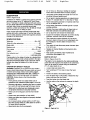
CRRFTSMRN°
15"
PLANER
Model No,
351.226151
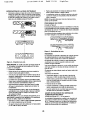
CAUTION: Read and follow
all Safety Rules and Operating
Instructions before First Use
of this Product.
Sears, Roebuck
www._ar_
and Co., Hoffman
conVcraftsm an
17857.00 Draft (01/11/02)
Estates, IL 60179 U.S.A.
RightFax
ii/14/2002
9:40
PAGE
PREPARE
•
Warranty ..................................
Safety Rules ..............................
Unpacking .................................
Assembly ................................
Installation ...............................
2
2-3
3
3-4
4-6
Operation ................................
Maintenance ............................
6-9
9-12
TroubLeshooting............................
Parts Illustration and LIst ..................
13
14-19
EspeSol ...............................
20-31
FULL
AREA
FOR JOB
Keep work area clean. Clutteredwork areas invite
accidents.
• Keep childrenoutof workplace.Makeworkshopchildproof. Use padlocks,master switchasor remove switch
kays to preventany unintentionaluseof powertools.
If this product fails due to a defect in materialor workmanshipwithin one year from the date of purchase,
Sears will at its option repair or replace It free of
charge. Contactyour nearest Sears Service Center
(1-800-4-MY-HOME) to arrange for productrepair,or
return this produ_ to place of purchasefor replacement.
If thls productIs used for commercialor rental purposes, this warrantywill applyfor 90 days from the date of
purchase.
This warranty applies only while this productIs used In
the United States.
TOOL SHOULD
BE MAINTAINED
• Always unplugtool priorto Inspection.
• Consult manualfor specificmaintaining and adjusting procedures,
• Keep tool lubricatedand clean for safest operation.
• Remove adjustingtools. Form habit of checkingto
see that adjustingtools are removed before switching machine on.
• Keep an parts In workingorder.Check to determine
that the guard or other parts will operate properly
and perform their intendedfunction,
• Check for damaged parts.Check for alignment of
movingparts, binding,breakage, mountingand any
other conditionthat may affect a toots operation.
This warrantygives you specificlegal rights and you may
also have otherrightswhich vary from state to state.
Sears, Roebuck and Co., Dept. 817WA, Hoffman
Estates, IL 60179
• A guard or other part that is damaged shouldbe
properlyrepaired or replaced.Do not perform
makeshiftrepairs. (Use parts list providedto order
replacement parts.)
WARNING: For your own safety,read all of the rules
and precautions before operating tool.
CAUTION; Always follow proper operating procedures
as defined In this manual even Ifyou are familiar with
use of this or similartools, Remember that being careless for even a fractionof a secondcan resultIn severe
personalInjury.
KNOW HOW TO USE TOOL
• Use right tool for job. Do not force tool or attachment
to do a Jobfor which it was not designed.
• Disconnecttool when changing blades.
• Avoidacoidentaistart-ul_ Make sure that the switch
Is In the OFF positionbeforepluggingin.
• Do not force tool, It will work most efficientlyat the
rate for which it was designed,
• Keep hands away from movingparts and cutting
FOR JOB
• wear properapparel. Do not wear loose clothing,
gloves, neckties,rings, bracelets or otherJewelry
which may get caught in moving parts of machine.
• Wear protectivehair coveringto contain long hair.
• Wear safety shoeswith non-slip soles.
• Wear safety glasses complyingwith United States
ANSI 7.87.1. Everyday glasses have onlyImpact
resistantlenses.They are NOT safetyglasses.
• Wear face mask or dust mask if operation Is dusty.
• Be alert and think clearly. Never operate powertools
when tired, Intoxicated or when taking medications
that cause drowsiness.
© Sears, Roebud_ and Co.
WORK
RightF&x
• Do not use powertools tn dangerous environments.
• Do not use powertools in damp or wet locations. Do
not expose powertools to rain.
• Work area shouldbe properlylighted.
• Proper electricalreceptacle shouldbe availablefor
tool Three prong plug shouldbe plugged directly
into properly grounded, three-prongreceptacle.
• Extensioncords shouldhave a groundingprongand
the three wires of the extensioncord shouldbe of
the correctgauge.
• Keep visitorsat a safe distancefrom work area.
ONE YEAR WARRANTY
BE PREPARED
3/33
surfaces.
• Never leavetool runningunattended.Turn the power
off end do not leave tool until it comes to a complete
stop,
• Do not overreach.Keep proper footing and balance.
• Never standon tool. Seriousinjurycouldoccuriftool is
tippedor if blade Is unintentionally
contacted.
• Knowyour tool. Learn the tool'soperation,application and specificlimitations,
2
RightFax
11/14/2002
•
•
•
•
•
9:40
PAGE
Use recommended accessories (refer to page 15).
Use of improper accessories may cause risk of
injuryto persons.
Handle werkpieca correctly. Protect handsfrom possible injury,
Turn machine oft if itjams. Blade jams when it digs
too deeply into workplese. (Motor force keeps it
stuckin the work.)
Always keep drive, cutterhead and blade guards In
place and in proper operating condition.
Feed work into blade or cutter againstdlrectfonof
rotation.
RightF&x
WARNING: Never usa highlyvolatile solvents.Nonflammable solventsare recommendedto avoidpossible
fire hazard.
WARNING: Do not attempt assembly if parts are
missing. Use this manual to order replacement parts.
PLANER
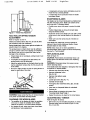
INSTALLATION
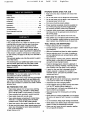
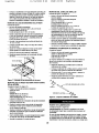
Refer to Figure20.
Before planer is assembled, a suitable locationshould
be chosen.The planer weighs approximately550 Ibs
when completely assembled.Planer shouldbe assembled on location.
CAUTION: Think safety! Safety Is a combination of
operatorcommon sense and alertness at all times
when tool is being used,
Planer needs to be set on a flat, level surface.This
improvesstability, accuracy and preventswarpage
and failure of cast components and welds. Adjust
machine levelersor use shimsas required.
Make sure there is arnple room on beth Infeedand
outfeed sidesof planerfor movingthe workplace
through the entire cut,There must be enough room
that neitherthe operatorsnor the bystanderswill
have to stand in linewith the wood while usingthe
tool.
WARNING: Do not attempt to operate tool untilit is
completely assembled acoordlngto the Instructions.
Check for shippingdamage. If damage has occurred,a
claim must be flied with carrier. Check for completeness. Immediately report missingparts to dealer.
Additionalparts which need to be fastenedto the planer
shouldbe locatedand accountedfor beforeassembling.
Planer is shipped assembled exceptfor the following:
two table extensionswifh rollers, handwhael, handle,
chip chute, knife gauge rod, two knife gauges, hardware
bag, 8/10 mm and 12/16 mm open-endwrenches, and
3, 4, 5 and 6 rnm hex wrenches.
Hardware bag includes:
• 8-1.25 x 20ram Hex Head Bolt (6)
• 6-1.0 x 12mm Socket Head Bolt (3)
•
•
•
•
•
•
•
•
•
•
•
4/33
Good lightingand correct power supply (230 volts)
are also requiredfor e properwork area.
Place planer in its designatedspot.Door panel for
access to motor is on back side.The planer is supplied with four moving handles that slide intothe
base on the infeedand outfeed sides.The planer
can be liftedby these handles and movedto the
required location.
MOUNT
6-1.0 x 12ram HexWasher Head Bolt (3)
6-1.0mm H_ Nut (3)
10-1.25mm Hex Nut (1)
6turnFlat Washer (6)
8mm Flat Washer (6)
10mm FlatWasher (1)
6rnrnLockWasher (3)
8-1.25 x 12mm Set Screw (6)
3 CMI-11 E-ring (4)
4x 4x 10mm Kay
Direction Indicator
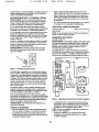
TABLE
EXTENSIONS
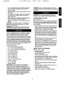
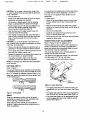
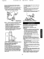
Refer to Figure 1, page 4,
• Required hardware:
8-1.25 x 20mm Hex Head Bblt (6)
8rnm Flat Washer (6)
8-1.25 x 12ram Set Screw (6)
• Mount table extensionto planer table on the lnfeed
side usingthree 8-1.25 x 20mrn he_ head boltsand
8mm flat washers, Do not tighten bolts.
• Thread three 8-1.25 x 12mm set screwsinto extensions.
•Placa long straight edge across table and table
extensions.
IMPORTANT: Table is coated wifh a protectant.To
ensure proper fit and operation, remove coating.
Coating Is easily removedwith mild solvents,such as
mineral spirits,and a soft cloth.Avoid getting solution
on paint or any of the rubber or plasticparts.Solvents
may deterioratethese finishes. Use soap and water on
paint, plasticor rubber components, After cleaning,
cover all exposed surfaceswith a light coating of oil
Paste wax Is recommended for table top.
• Adjust set screws sothat the table extensionis at
the same heightas the table.
• Tighten baits to secure extension.
• Repeat above steps for the outfeed e0(tension.
3
RightFm×
ii/1412002
9:40
PAGE
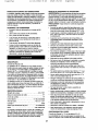
KNIFE
5/33
GAUGE
RightF&×
ASSEMBLY
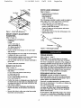
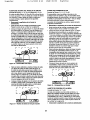
Refer to Figure2.
• Required parts and hardware:
Knife Gauge Rod
Knife Gauge (2),
3-CMI 11 E-Ring (4)
The knife gauge assembly Is used to verify the height of
bladeedges and to make adjustments if necessary.
• Slide knifegauge onto knife gauge rod.
• Positionknife gauge on the rod so that there is a
grooveon eitherside of gauge.
• Press In E-rings,one in each groove,end secure
knife gauge position.
• Repeat above steps for the other knifegauge on the
otherend of the rod.
Figure 1 - MountTi 4e Extensions
MOUNT HEIGHT
HANDWHEEL
ADJUSTMENT
¢J_0
Refer to Figure 19.
Required parts and hardware:
Handwhael
Handle
4 x 4x lOmm Key (1)
lOmm Flat Washer (1)
10-1.25mm Hex Nut (1)
Direction Indicator (1)
• Positionthe k_=yin the keyway on the worm shaft
"
rod
•
Figure2 - KnifeGaugeAssembly
(KeyNo. 58).
• Slide handwheel over worm shaft sothat the keyway
isaligned with key on worm shaft.
• Slide the direction Indicator on the worm shaft. Make
sure the directionindicatorpointscorrectly.
• Use flat washer and hex nut to secure handwheelto
worm shaft.
• Thread handle intohandwhael.
MOUNT
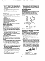
POWER
Refer to Figure 3, page 5.
WARNING: Do not connectplaner to the power
sourceuntil all assembly steps have been completed.
The motoris designedfor operation on the voltage and
frequency specified.Normal loads will be handled safely on voltagesnot more than 10% above or below specifiedvoltage. Runningthe uniton voltageswhich are not
wifhln range may cause overheatingand motor burnout,
Heavy loadsrequire that voltageat motorterminals be
no less than the voltage specifiedon nameplate.
CHIP CHUTE
Refer to Figure 19.
• Required parts and hardware:
Chip Chute
6-1.0 x 12ram Hex Washer Head Bolt (3)
6-1.0mm Hex Nut (3)
6ram Flat Washer (6)
6-1.0 x 12ram Socle_tHead Bolt(3)
6ram LockWasher (3)
GROUNDING
INSTRUCTIONS
WARNING: Improper connection of equipment
groundingconductor can resultIn the risk of electrical
shock.Equipmentshouldbe groundedwhile In use to
protectoperatorfrom electricalshock,
• Positionchip chute on chipbreakercover (Key No. 68)
so that the slotson chip chute and chlpbreekercover
are alignedand slots on chip chute and holes on the
rollercase are aligned.
• Secure chipchute to chlpbreakerusing three hex
washer head bolts,six flat washers and three he:<
nuts.
•
SOURCE
Check with a qualified electricianif groundinginstructions are not understoodor if in doul_ as to whether the
tool Is properlygrounded.
This tool ts equippedwith an approved3-conductor
cord rated up to 250V and a 3-prong groundingtype
plug rated at 250V (See Figure3) for your protection
against shock hazards.
Secure chip chute to roller case using three socket
head bolts and lock washers.
Do not remove or alter groundingprongIn any manner.
In the event of a malfunction or breakdown, grounding
provides a path of least reslstancafor electrical shock.
4
Righ%F&x
11/14/2002
9:40
PAGE
WARNING: Do not permit fingers to touch the terminals of plug when installing or remevlncfrom outlet.
6/33
RightFax
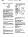
volt magnetic contactor that is prewired in the factory
(See Figure 4),
Black
Red
Ground
Grounding Pin
Figure 3 - Grounding Methods
Plugmust be pluggedintoa 230V matchingoutlet(See
Figure3) that is properlyinstaUedand groundedin aocerdance with all localcodes and ordinances,Do notmodify
plug provided.If it will notfit in outlet,have properoutlet
Installed_ a qualifiedelectrician.
Inspect tool cords periodically,and if damaged, have
repeited by an authorized servlse facility,
Ground
Motor
White
SetThermal
18 AMPS
Green (or green and yellow) conductorin cord is the
groundingwire. If repair or replacement of the electric
cord or plug is necessaw, do not connect the green (or
green and yellow) wire to a live terminal.
Where a 2-pmng wall receptacle Is encountered,it
must be replacedwith a properlygrounded3-prong
receptacle installedin accordance with National Electric
Code and local codes and ordinances.
WARNING:
This work should be performed
qualified electrician.
EXTENSION
Ovedoadto
To Motor
Rgure 4 - Magnetic Contactor Wiring Schematic
• The tool has a key lock switchto prevent unauthorized use. Turn key lock switchto OFF and remove
key when tool is not in use.
NOTE: The motorwellnot start ifthe key is in the OFF
position
by a
CORDS
• The use of any extensioncord will cause some drop
Lnvoltage and loss of power.
• Wires of the extension cord must be of sufficientsize
to carry the currentand maintainadequate voltage.
• Use the table to determine the minimumwire size
(A.W.G.) extensioncord.
* Use only 3-wire extension cords having3-prong
groundingtype plugs and 3-pole receptacleswhich
accept the tool plug.
If the extension cord is worn, cut, or damaged in any
way, replace it Immediately.
EXTENSION CORD LENGTH
Wire Size
,Mt
• Connect planer to a supplycircuit protectedby a 20
AMP circuitbreaker or time delay fuse.
OVERLOAD
PROTECTION
The magneticcentactor has overload protectionthat
helpsto preventdamage to the motor.The overload
protectionwill automaticallyturn offthe magneticcentactor when an overloadoccurs.Set thermal overloadto
18 Amps. Be sure to disconnectplaner from power
sourcewhen resettingoverload protector.The protection is reset by opening the contactor boxand pressing
the reset button.
CHECK
A.W.G.
CONNECTIONS
• Plug in the line cord to a 230 volt power source.
• Turn the key to ON,
Upto 50ft ................................
14
NOTE: Using extension cords ever 50 ft. long Is not
recommended.
• Turn and release the stop button,
• Depress the start button.The motormust mtate
counterclockwise facing shaft end.
• Depress the stop button.The motor must stop.
• Depressingthe start buttonwith either the stop
buttonpresseddown or the key In OFF position
must not start the motor.
ELECTRICAL
CONNECTIONS
Refer to Figure 4.
WARNING: All eleotricalconnections mustbe performed by a qcallfled electrician. Make sure unit is off
and disconnectedfrom power sourcewhile motoris
mounted,connected, reconnectedor anytime wiring is
Inspected.
Planerhasan approved230 volt
three-conduotor
line
curdwitha three-prong
grounding
typeplug,and a 230
• If any of the above steps do not work properly,disconnectplaner from power source and recheckthe
connections.
5
RightFax
11/14/2002
9:40
PAGE
Refer to Figures5-20.
Craftsman 15" Planer is a heavy duty cast iron unitthat
can plane lumbar upto 15"wide and 6" thick`Planer
has a 3" diameter, 3-blade cutterheadwith jack screws
for easy blade adjustmentand replacement.Cutterhead
and feed rollerstravel on precision ground steel
columns.Lumber can be fed at 16 or 20 feet per minute
and can be cut up to ',V"deep per pass.
Planar comes with totallyenclosedwelded plate steel
cabinet with built-inmobile base, 4" port for dust collection and safety electrical controlwith magneticcontector.
includes3 HP RPM motor.
Maximum cut.........................
Floor space .....................
V-pelts .................................
Dust collectionport ..................
Supportthe workpiece adequately at all times during
operation;maintain controlof the workpieca.
Take precautionsagainst kickback.Do not permit
anyoneto stand or cross in line of cutterheads rotation. Kickbackor thrown debriswill travel In this
direction.
20 x 15'/,"
51"
Bladewidth ..............................
15"
Turn switchoff and disconnectpowerwhenever planer is not in use.
,/," Deep
4-3'hx 51 x 31"
M-60
Replace or sharpen bladesas they become damaged or dull.
Keep planar maintained.Followmaintenance
instructions (See pages 9-12).
4" Diameter
Motor .........................
3 HP, 3500 RPM
Planing refers to the sizing of lumbar to a desired thickness while creating a level surface parallel to the oppcsite size of the board. Depth of cut is the term used to
Indicate how deep the blades will cut Into the work-
DEPTH
SAFETY
OF CUT
Refer to Figures 5 and 19.
The depth of cut is adjusted by the relative positioning
of the table with respect to the blades in the cutterhead.
Table can be raised or lowered using the handwheel
("A"). To adjust depth of cut:
piece.
OPERATION
KiEhtFax
Do not force cut. Slowingor stalling will overheat
motor. Allow automaticfeed to functionproperly.
Use quality lumber.Blades last longerand cutsare
smootherwith good qualitywood.
Do not performplaningoperations on material shorter than 17•, narrowerthan s/,,, or less than '/="thick,
Never make planing operationon materialwider than
15" or cut deeper than ',V'
Always keep cutterhead and blade guards in proper
workingcondition.
Maintainthe properrelationshipsof Infeed and outfeed table surfacesand cutterheadblade path.
Do not pack the work toward the infeedtable.
DESCRIPTION
SPECIFICATIONS
Table size ..........................
Table with rollerextensions ..................
7/33
RULES
WARNING: Operation of any power tool can resultIn
foreign objects being thrown into eyes which can result
in severe eye damage. Always wear safety goggles
complying with United States ANSI 7_87.1(shownon
package) before commencingpowertool operation.
CAUTION: Always observe the following safety
precautions:
• Know general powertool safety.Make sure all
precautionsare understood(See pages 2, 3 and 6).
• Whenever adjusting or replacingarTyparts on planer,
turn switchoff and remove plugfrom powersource.
• Make sure the cutterhead and chipbreakercovers
are properly attached and securelyfastened.
• Make sure all moving parts are free from interfer-
•
Loosen table lock knobs ("B").
•
Turn handwheel
wheel
CA") to raise or lower the hand-
•
Position the table at the desired position.
•
Turn the planer key to ON position, release the stop
button and press the start button.
Feed the lumber from the Infeed side.
•
• Use the scaleon the columnsto measure the depth
of cut.
enoe.
• Always wear eye protection or face shield.
•
Make sure blades are aligned and properly attached
to cutterhead.
• Do not plug in planer unless switch is in OFF position. After turning switch on, allow planer to come to
full speed before operating.
• Keep hands clear of all moving parts.
Rgure 5- Depthof CUt
6
RightFax
11/14/2002
9:40
• To increase depth of cut raise the table:to decrease
depth of cut lower the table.
• Tighten the table lock knobs.
• When planingseveral pieces of wood, plane all the
lumber with the same set-up to have uniformthickness removed.
A depth of cut limiter (Figure 19, Key No. 38) is
provided to limit depth of cut to maximum of 'At
Do not make planing outs deeper than _,V'.
ADJUSTING
BLADE
6_
•
•
8/33
RishtFax
• Repeat the previoustwo steps to adjustthe blade
height on the other end of the blade.
• Secure blade and glb bytighteninggib screws.
Tighten outside gib screwsfirst, and then, working
towards center, tighten the remaininggib screws.
• Repeat the above steps for remaining blades.
Securely tighten all gib screws.
• Replace chipdeflector plate.
• Replace cutterheadcover.
• Replace chip chute.
HEIGHT
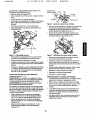
Refer to Figures 6, 7 and 19,
CAUTION: Planer blades are very sharp. Use laather
gloves to protecthands from injury and exercise caution
when adjustingblades.
WARNING: Disconnectplaner from power source
before adjustingplaner.
To produce even surface on a workplace,the blade
edges must be the same distancefrom axis of cutterhead. The blade height comes adjusted from the factory
and would not raqulra any adjustment.However,if
adjustments are required;
• Loosen and remove hex washer head boltsand hex
head bolts (Key Nos. 10 and 5) and removechip
chute (KeyNo. 69).
• Loosen and remove hex washer head bolts(Key No.
10) and remove chipbraaker cover (Key No. 68).
• Loosen five gib screws (Key No. 14) on the cutterhead to loosen the cutterheadgib (Key No. 13).
Blade
Height
leg
JackScrew
Gauge'_
Figure 6-
PAGE
PREPARING
•
THE WORK
Do not plane dirty boards. Dirt and small stones are
abrasive and will wear the blade.
Remove nails and staples to avoiddamaging the
blades.
• Avoid knots. Heavy crossgrain makes knots hard.
Also knots san come loose and jam the blade.
•
•
The planer works best when the lumber has at least
one flat surface. Use a surface planer or jointer to
define a flat surface.
Twisted or severely warped boards can jam the
planer. Rip lumber in half to reduce the magnitude
of the warp.
FEEDING
•
WORK
Feed work along the grain direction. Wood fed
against the grain will result in chipped and splintered
edges. Sometimes grain will switch direction in the
middle of a length of board. If possible, cut board
before planing (See Figure 8).
Rotation
Blade Height Adjustment
Position the knife gauge assembly on the cutterhead
so that both the legs of the gauge rest firmly on the
cutterhead. Remove chip deflector plate (Key No, 7)
if required.
The blade edge must just make contact with the tab
on the knife gauge. Adjust blade height by turning
the jack screw (Key No. 15),
Against the Grain
Rotation
Grain----->.
I
!
\
I
!
!
i
Figure 8 - Direction ot Grain
Rgure 7 - Checking Blade Height
-._-_Grain
m
RightF&x
iii14/2002
9:40
PAGE
Turn the planer on.
Stand on the side of the planer to which the height
adjustment handwheal was attached.
•
Lift the workto infeed support roller by grasping
edges at approxlmeteiy the middle of the length,
•
Boards longer than 24" should have additional support from free standing material stands (See
Recommended Accessories, page 15).
•
Rest the board end on infeed support roller and
direct the board Into the planer.
The snipe is more apparent when deeper cutsare
being taken.
To reduce snipe:
• Gently, liftthe board slightlywhen the board Is fed
untilthe outfeadroller comes in contactwith the
board.
• Release the board when beth infeed and ouffaad
rollersare in contactwith the beard, and the beard is
beingfad.
• Move to the outfaed side.
• Gently lift and supportthe board when all of the
beard has left the infeed roller.
•
Push slightly on board and allow automatic feed to
takB the board. Release beard and allow automatic
feed to function properly. Do not push or pull on
workpiace.
CAUTION: Do not stand directly in line with front or
rear of planer. When an object is projected from planer
it will travel in this direction.
•
Move to the side and receive the planed lumber by
grasping it in the came manner in which it was fed,
•
Do not grasp any portion of the board which has not
gone past the outfeed support roller,
•
Repeat this operation on all beards which need to be
the same thickness or adjust the height.
•
The planer has return roflers on the top so an
assistant can pass work beck to the operator,
RightF&x
An unevenforce is created when only one feed rolleris
in contactwith work at the beginningor end of cut.
CAUTION:
Do not plane a beard which Is less than
17" long. The force of the cut could split the board and
cause a kickback,
•
•
9/33
• When planing more than one beard, buttthe boards
together to reduce snipe.
POWER
FEED RATE ADJUSTMENT
Refer to Figures 10 and 1% pages 8 and 9.
Feed rate refersto rate at whichwood is passed over
blades.The Craftsman 15" Planer is suppliedwith a
powerfeed systemthat automaticallyfeeds the wood
Intothe planer under the cutterhead.
The powerfeed system uses a 2 speed gearbox for
planing beth herd and softwoods.
Low sbeed-6 FPM (feet per minute) Isfor hard wood,
and high speed-20 FPM is for soft wood.
• Adjust power feed ratewhile planer is running.
NOTE: An assistant must follow the same precautions
as the operator_
C U'I-I'ING
DEPTH
Refer to Figure 9.
The surface finish the planer provideswill be smoother
it a shallowerdepth of cut Is used.The depth of cut Umiter at ',_"indicatesthe intended maximum depth of cut.
Deep cuts require more power and cause greater wear
on all machine parts.
-4e----- Power
Feed Knob
Figure 10 - Power Feed Knob
• To engage power fead at low speed (16 FPM), pull
engagement knob out away from planer (See Figure
11).
• To engage high speed (20 FPM), push engagement
knob in all the way, towardsplaner (See Figure 11).
• The powerfeed system can be disengaged by placIng the engagement knob In the middle or neutral
position(See Figure 11).
Rgure 9- CuttingDepth
SNIPE
Snipe Is a depressionat either end of the beard,
caused by an unevenforce on the cutterbeedwhen
work is entering or leeving the planer,
Snipe will occur when beards are not supported
properly,A slight snipe may stni be noticedwhen the
board Is supported,
8
_ightFax
11/14/2002
9:40
PAGE
m
10/33
•
A raised grain will ocour when dull blades pound on
wood that has a varying density.
•
A raised edge will be produced where the blades
have been nicked.
i
SHARPENING
O
20 FPM
0 FPM
RightFax
BLADES
The blades can be honed individually by whetting them
with fine sharpening stone. Make sure oilstone is flat
and is not worn. To sharpen blades:
•
Partially cover stone with paper to protect the table
top.
• Position infead table so stone will contact blade
along its beveled surface.
• Stroke the stone across blade from one side to other
while stone is also moving slightly in the direction of
feed.
Figure 11 - Power Feed AdJuldment
FEED
ROLLER
SPRING
TENSION
ADJUSTMENT
•
Refer to Figures 12 and 19.
Infeed and outfeed rollers (Key Nos. 36 and 35) feed
the workplace under the cutterhaad.
tf the blades are nici_d they must be replaced or
reground. Never install unbalanced blades. Always
sharpen blades in sets of three.
Swing-loaded feed rollers press against workplece to
prevent rollers from slipping.
NOTE: Many shops do not have capabilities to
resurface blades. Yellow pages should list "Sharpening
Services" or "1"ool Grinding".
The spring tension on feed rollers must be sufficient
enough to prevent rotlers from slipping on wcrkpiece,
but tension must not be so great that rollers cause
damage to the workplace.
•
REPLACING
BLADES
Refer to Figure 19.
CAUTION: Planer blades are extremely sharp, Usa
leather glovesand _0cercisecaution when replacing
blades.
If feed milers slip on workpfece, spring tension must
be increased.
•
If workpleca is damaged by the feed rollers,the
springtension must be decreased.
• Adjust the springtension on the feed rollersby rotatingthe adjustment screws (Key No. 53) at each end
of the rollers.
•
Make sure to do the same amount of strokes on
each blade.
WARNING: Disconnectplaner from power source
before replacingblades.
If the blades have been chippedor damaged, they must
be replaced.To replaca blades:
• Remove chip chute (Key No 69),
• Remove chipbreakercover
(Key No. 68)
• Remove chip deflector plata
(Key No. 7).
Be sure to adjust screws so that the springtension is
equal on each side of the roller.
• Loosen gib screws(Key No. 14).
* Carefully remove blade.
• Thoroughlyclean cutterhaad slots, gibs, and gib
screws.
• insert new or sharpened bladesin cuttarhead,
• Replace gib,
Figure 12 - Roller Spdng Tenelon
• Secure blade by tighteninggib screws.See
"Adjusting Blade Height"page 7,
• Repeat the previoussix stepsfor the other blades,
WARNING: Make certain that the unit Is disconnected
from power source before servicingblades.
CHECKING
•
•
FOR
WORN
ADJUSTING
BLADES
BELT TENSION
Refer to Figures 19 and 20.
The condition of the blades will affect the precision
of the cut. To check the condition of the blades,
observe the quality of cut which planer produces.
Dull blades will tear, rather than sever wood fibers,
and produce a fuzzy appearance.
•
9
Belt tension must be checked periodically. To check:
Remove pulley cover and knobs (Figure 19, Key
Nos. 44 and 45).
RightFax
11/14/2002
9:40
PAGE
11/33
R±ghtF&x
•
Adjust bolt tension by pivoting motor mounting plate
(Figure 20, Key No. 13). Pivot plate by loosening he_
nuts on tension bolt (Figure 20, Key Nos. 11 and 14)
as required.
• Be sure that both ends of the table rollersare at the
same heightso that the rollersare parallel with the
table and secure eccentricadjusterswith set screws
(Key No. 73),
•
Belt ts properly tensioned when slight pressure
between thumb and inde_€finger causes '/z" deflection of bolt.
ADJUSTMENT
•
Be sure to replace pulley cover and knobs,
LUBRICATION
The planer gearbox has been filled with lubrioatingoil
at the factory. The gearbox oil shouldbe changed each
30 hours of operation.To change o11:
• Drain old gearbox oil by removingplug at bottomof
gearbox.
• Replace drain plug.
• Remove fill plug at top of gearbox,
• Fill gearbox with 50 or 60 weight gear o11.
• Fill untiloll level Is up to plug hole.
• Replace fill plug.
Frequentlylubricate sliding surfacesof columnswith
graphite or industrialgrease.
ANTI-KICKBACK
BLOCK
Refer to Figure 13.
Some of the maintenance adjustmentsrequire the use
of a handmade adjustment block (See Figure 13).
Make this block out of hard wood scrapwith the
dimensionsshown. Exact dimensionsare not critical
but a very smooth, level finish acrossthe top Is
required.
_"11 i'_- ,_
_
1'/_1_-
PAWLS
Refer to Figure 19,
The anti-kickback pawls (Key No. 21 ) prevent the workpiece from kicking back against the direction of feed.
The pawls must rotate freely to ensure safe operation
of the planer.
•
Inspect the anti-kickback pawls daily for proper operation checking that the pawls rotate freely.
•
Clean the pawls of all gum and chips as required to
ensure safe operation.
TABLE
ROLLER
Figure 13 - Adjustment
OUTFEED
ADJUSTMENT
•
For all workplace materials and finishes the table
rollersshould be positionedslightlyabove the table.
ADJUSTMENT
• Disconnect planer from power source.
• Adjust bladeheight properly(See "Adjusting Blade
Height".page 7).
• Place adjustmentbiock(Figure 13) under cutterhead
at one end as shownIn Figure 14. Place 1ramfeeler
gauge between blockand blade. Raise or lower table
so that blade just contactsfeeler gauge when blade
is at lowest position. Put gearbox in neutraland rotate
cutterhead slowlyto determine lowestposition of
blade.Locktable in position _ tighteninglockknobs
(Figure20, KeyNo. 75). Do not unlocktable position
untilboth sidesof ouffeedrollerhave been adjusted.
The proper height of the table rollers is dependent upon
the hardness and surface finish of the work,piece:
• The roller height shouldbe adjusted so that the
workplace feeds smoothlythroughthe planer but is
not damaged by the table rollersor by the feed
rollers.
Rough cut wood requiresthe rollersto be adjusted a
littlehigher, while smoothfinish wood requiresthe
rollersto be a little lower.
HEIGHT
Refer to Figures 14, 15, 19 and 20.
The outfeed roller (Figure 19, Key No. 35) is set at the
factory so that the outfeedroller Is positioned 1ram
belowthe blade.The outfeed rollershouldneed no
further adjustment but can be checkz_dand adjusted
usingthe following procedures:
Refer to Figure 20.
The table rollers (Key No. 59) are free-spinningrollers
that help reduce friction, makingthe planingoperation
smoother.
•
ROLLER
Block
l"
,
O"
'
I-.__
• Table roller height Is adjusted by looseningset
screws (Key No. 73) and rotatingeccentricadjusters
(Key No. 57).
• Use a straight edge acrossthe table and table
rollersto check miler adjustment.
,°rOooo°
"]
Figure 14 - Cutterheed w£h Block
10
I
_J
RightFmx
11/14/2002
9:40
PAGE
12/33
RightFmx
Remove feeler gauge and slide adjustment block
under outfead roller (See Figure 15). Outfead roller
should Just contact adjustment block. If outfeed roller
is too high or low loosen hex nut on set screw
(Figure 19, Key Nos. 3 and 29) under outfead roller.
Rotate set screw to position outfeed roller properly.
Secure position by tightening hex nut on set screw.
Place adjustment block on other end of outfead miler
and repeat step 4 above. Be sure that outfeed roller
is at the came height on both ends so that the roller
is parallel with the table.
I
o
Figure 16 - Chlpbreaker with Block
ADJUSTING
.O"
]
TABLE
POSITION
Refer to Figures 13. 17 and 20.
The table is positioned parallel to the cuttarhead at the
factory and should need no further adjustment. If the
planer is cutting one side of the workpleca deeper than
the other producing a tapered cut, then the table may
need to be adjusted. Check to see that the blades are
adjusted properly, see =Adjusting Blade Height" page 7.
• Disconnect planer from power source.
Figure 15 - Outteed Roller with Block Adjustment
CHIPBREAKER
•
ADJUSTMENT
Refer to Figures 13, 14, 16, 19 and 20.
The chipbreakerbreaks the chips of wood that are
created by the blades during the planingoperation.The
chipbreakerthen directsthe chipsaround cutterhead
and out of the chip chute.The chlpbreakermust be
positioned1ram below cutterhead to operate properly.
The chlpbreakerposition is checked and adjusted by
using the followingprocedure:
• Dlsconneot planer from power source.
• Adjust blade height properly (See =Adjusting Blade
Height", page 7).
Place adjustment block (See Figure 13) on table at
outside edge of roller case and on infeed side of
planer. Slide block to one corner of roller case. Raise
or lower table until block Just contacts roller case.
Lock table in position by tightening lock knobs (Key
No. 75). Do not unlock table position until all four corners of the roller case have been checked.
• Slide blockto other side of rollercase on infead side
of table. Check to see that the blockjust contacts the
roller case.
•
• Place adjustment block (See Figure 13) under cutterhead at one end as shownin Figure 14. Place lmm
feeler gauge between blockand blade. Raise or
lower table so that blade just contacts feeler gauge
when blade Is at lowest pesitlen. Put gearbox in neutral and rotate cutterbead slowlyto determine lowest
positionof blade. Lock table in pesitlon by tightening
lock knobs (Figure20, Key No. 75). Do not unlock
table positionuntil both sides of chipbreakerhave
been adjusted.
• Remove feeler gauge and slide adjustmentblock
under chipbreaker (See Figure 16). Chlpbreaker
shouldJustcontact adjustment block.If chipbreaker
is too high or too low, loosen hex nut on set screw
(Figure 19, Key Nos. 3 and 29) under chipbreaker,
Rotate set screwto position chlpbreakerproperly.
Secure positionby tightanlnghex nut on set screw.
• Place adjustment blockon other end of chlpbreaker
and repeat steps 3 and 4 above. Be sure that chipbreaker is at the same height on bothends so that
the chipbreakeris parallel with the table.
•
Move adjustment block to outfead side of table and
check height of both sides of roller case. Adjustment
block should just contact roller case. If all four corners of roller case are at the came height, then roller
case and cutterhead are parallel to the table.
If roller case Is not parallel to the table, then the
table must be adjusted. Loosen the two bolts holding
the chain tension sprocket (See Figure 17). It may
be necessary to remove bolt "A" to release the tension in the chain.
Rgure 17 - Chain Tension Bracket
11
RightF_x
11/14/2002
9:40
PAGE
The table height is adjusted by removingthe chain from
the corner sprocketsand rotatingthe sprockets.
Determine which corner or corners, need adjustment
and remove the chain from the sprocketin that corner.
Rotate the sprocketby hand to adjust the table height
(be sure to leave other sprocketsuntouched).
NOTE: Be careful not to rotate each sprocketmore
than 1 or 2 teeth.
Rotate sprocket(or sprockets)untiltable Is parallelto
rollercase. Assemble chain tension sprocketcarefully
and tension chain properly.
12
13/33
RightF&x
RightFgx
11/14/2002
9:40
PAOE
RightFax
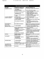
CORRECTIVE
SYMPTOM
POSSIBLE
Planer does not start
1.Key is In the OFF position
?_Stopbuttondepressed
3.No powerto ptaner
CAUSE(S)
4.Motor overload protection tripped
5.Defective or loose switchor wiring
i Frequentopening of fuses or
circuitbreakers
14/33
ACTION
1.Turn key to ON position
?-Turn and release stop button
3, Have a qualified electriciancheck power
source
4. Reset motoroverloadprotection,
eee"Overload Protection".page 5
5. Have a qualifiedelectriolancheckthe
switchesand wiring
1.Motor overloaded
?-Fuses or circuitbreakersdo not
have sufficientcapacity
3.Circuit overloaded
4.Motor wired incorrectly
1.Reduce load on motor
2, Have correctfuses or circuitbreakers
Installed
3. Reduce circuit load (turn off other appllancesl
4. Rewire motor using the schematicon the
motor for high voltage
Cutterhaad turns in the
opposite direction
Motor wired incorrectly
Rewire motor usingthe schematicon the
motor for high voltage
Excessive snipe
(gouging at end of board)
1.Dull blades
1. Replace or sharpen blades per instructions
see "Maintenance". page 9
?_Inadequate support of long boards 2. Support long boards
3.Uneven feed rollerpressure
3.Check feed rolleroperation
4.Cutter castingnot aligned
4.Check positionof elevation screws
5.Butt end to end each piece of stockas
5.Lumber not buttedproperly
boards passthrough planer
6.Support rollers misaligned
6.Adjust supportrollers
Fuzzy grain
Ptanlng wood with high moisture
content
Remove high moisture content from wood
by drying
Torn grain
1.1oo heavy of a cut
2.Blades cutting against grain
3.Dull blades
1. Review "Depth of Cut", page 6
2. Review "Feeding Work", page 7
3. Replace or sharpen blades per instructions
see "Maintenance", page 9
Rough raised grain
1.Dull blades
?-Too heavy of a cut
1. Replace or sharpen blades per instructions
see "Maintenance", page 9
?-Review "Depth of Cut", page 6
3.Moisture content too high
3. Dry the wood or use dried wood
Uneven depth of cut
(tapered cut)
Cutterhead not parallel with table
Adjust table, see "Adjusting Table Position",
page 11
Belts slipping
Loose pelts
Tension belts, see "Adjusting
page 11
13
Belt Tension",
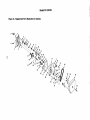
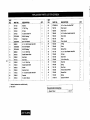
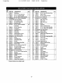
Model351.226151
cP
:<
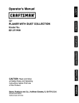
Figure
18 - Replacement
Parts Illustration
for Gearbox
)=_
)=_
11
35
t_
0
0
rO
10
15
16
.10
18
9
39
/
/
3O
"0
>
o
M
26
01
32
23
24
O3
29
'm
i..J.
22
8
0q
27
×
:d
,-z
×
KEY
NO.
I
PART NO.
DESCRIPTION
7311.00
Gearbox
2
7312.00
3
7313.0D
V4"NPT Plug
Oil Seal
4
7314.00
8 x 2OmmDowel Pin
KEY
NO,
PART NO.
DESCRIPTION
1
22
STD833016
6ol.0 x 16mm Hex Head Bolt*
1
2
23
7327.00
ChainGuard
2
1
24
7326.00
ChainCover
1
2
25
726g.00
8-1,25 x 50ram SocketHead Bolt
1
2
26
7330.00
Drive Chain
1
1
27
7331.00
(nob
1
p*
F..*
p_
OTY,
QTY.
5
STD315245
6
7316.00
6204LL Bearing*
Helical Gear
7
STDB51006
6ram Flat Washer*
1
28
7332.00
Clutch Handle
1
5
3806.00
6-1.0 x 10ram SocketHead Bolt
3
29
7333.00
O-Ring
1
9
STDB51008
STD315215
5mm Flat Washer*
1
30
7334.00
Clutch
1
6201ZZ Beadng*
5
31
8102.00
32
7317,00
Spring Hook
6-1.0 x 12mm Washe[ Head Bolt
1
1
1
33
7336.00
OII Seal
1
Io
11
383g.00
5
12
731g,0o
5 x5 x 10ram Key
Double Geared Shaft
13
7320,00
SpurGear
1
34
7337.00
Gear Shaft
1
14
732t .0O
Spur Gear
1
35
7338.00
7339.00
6 x 6 x 40ram Key
Steel ball
1
36
1
15
r322.00
5 x5 x 12ramKey
1
16
r323.00
1
37
7340.00
Spring
1
17
7324.00
Single Geared Shaft
Gasket
1
38
7341.00
1
18
7325.00
GearboxCover
39
?398.00
Spur Gear
TensionBracketwheel
40
7399.00
BracketBolt
1
7400.00
Spring
1
17857,00
Operator's Manual
1
19
1775.00
6-1.0 x 25turnSocket Heed Bolt
1
6
2o
7326.00
Sprocket
1
41
21
7397.00
6 x 22mm Spacer
1
A
0
0
>
Q
1
_J
H-
o_
&
Standardhardwareitem av_lable IocaJly
Not Shown
ecommended
Accessories
IsuppoStand
I 214t7
p_
x
RightFax
9:40
11/14/2002
PAGE
17/33
RightFax
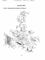
Model 351.226151
Figure
19 - Replacement
Parts Illustration
for Rollercase
45
63
7
16
RightFax
KEY
NO.
11/14/2002
9:40
18/33
RightFax
KEY
NO. PART NO.
DESCRIPTION
37
7289.00
6-1.0 x 10mrn Flat Head Screw
2
38
39
40
41
7290.00
0316.00
STD541031
STD551031
Depth Limlter
6-!.25 x 12ram Set Screw
5/1s"-1
8 Hex Nut*
5/_,,,FlatWasher*
1
1
2
2
42
43
7291.00
7292,00
Belt Pulley Guard
M-60 V-belt
2
3
44
45
46
7293.00
7294.00
7295.00
Belt Pulley Cover
Knob
KnobBolt
1
2
2
47
48
49
0519.00
1505.00
0865.00
3AMI-12 Retaining Ring
6-1.0 x 12turn socket Head Bolt
6-1.25 x 20mm Hex Head Bolt
1
2
1
50
STD852008
8ram Flat Washer'*
1
51
7297.00
Driven Pulley
1
1
52
53
STD315255
7299.00
6205ZZ Bearing*
RollertensionAdjustment Screw
1
4
1
1
1
54
55
56
7300.00
3806.00
7301.00
SpringPlate
6-1.0 x 10mm Sod._t Head Bolt
Crank Case
3
12
1
3CMI-20 E-ring
Anti-kickback Pawl
2
50
57
55
1531.00
7302.00
4x 4x 10ram Key
Worm Shall
1
1
7278.00
7279.00
7280.00
STD833016
Spacer
Anti-kickback Pawl Shaft
Driven Chain
6-1.0 x 16ram Hex Head Bolt*
64
1
1
2
59
60
61
62
STD315205
1465.00
7304.00
STD652010
6200ZZ Bearing*
3BMI-30 Retaining Ring
Handwheel
10ram FlatWasher*
1
1
1
1
7281.00
7282.00
7283.00
STD840610
1822.00
6 x 22ram Spacer
Outfeed Sprockat(do. hle)
Infeed Sprocket
6-1.0mm H_ Nut*
6-1.25 x 20mm Socket Head Bolt
2
1
1
9
4
63
64
65
66
1351.00
7305.00
7306.00
7307.00
10-1.25 H_ Nut
Handle
Roller Bracket
_oller
1
1
3
2
Brank_t
Retaining Brackat
Spring
5 x 5 x 23mm Key
Outfeed Roller
4
4
4
2
1
67
68
69
7308.00
7309.00
7310.00
Chip Breaker
ChipbreakerCover
Chip Chute
1
1
1
Infeed Roller (serrated)
1
70
71
72
73
7315.00
8103.00
8104.00
! 6555.00
Knife Height Gauge
Directionindicator
Gauge Rod
3 CMI-11 E-Ring
2
1
1
4
PART NO.
DESCRIPTION
1
2
3
7265.00
0394.00
1640.00
Rollercase
10-1.5 x 12ram Set Screw
6-1.0 x 16ram Set Screw
1
8
7
4
5
6
7266.00
STD833012
STD851006
8-1.25 x 50ram SocketHead Bolt
6-1.0 x 12ram Hex Head Bolt*
6ram Flat Washer=
4
5
9
7
8
9
10
7267.00
1596.00
7268.00
7317.00
Chip Deflector Plate
6 x 20ram Spring Pin
Retaining Plate
6-1.0 x 12ram Hex Washer
Head Bolt
11
12
7269.00
7270.00
8 x 6 x 36rnm K_
Cutterhead
13
14
15
7271.00
0996.00
3835.00
Cutterhead Gib
Gb Screw
Jack Scr_/
16
7272.00
Planer Blades (set of 3)
17
18
19
7273.00
BTD841217
7275.00
Chip Deflector Shatt
12-1.75mm H= Nut*
Shatt
20
21
7276.00
7277.00
22
23
24
25
26
27
28
29
30
;127264.00
7285.00
33
7286.00
134
0259.00
35
7287.00
36
PAGE
7288.00
QTY.
1
2
4
20
1
1
3
15
6
I
Standard hardware _em available locally
17
QTY.
RightF&x
11/14/2002
9:40
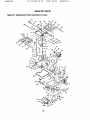
Model
Figure 20 - Replacement
PAGE
19/33
KightFmx
351.226151
Parts Illustration for Base
65
67
67
66
4O
67
37
18
RightF&x
11/14/2002
9:40
PAGE
KEY
NO, PART NO.
KEY
?.
PART NO.
2
3
4
5
6
7
8
9
_10
11
12
13
14
15
116
117
18
19
20
21
i22
23
24
25
26
27
28
29
3O
31
32
33
34
36
37
39
40
41
4,3
44
7344,00
7345.00
7346.00
7347.00
7351,00
7383.00
7390.00
7350,00
0781,00
0582.00
1351,00
STD551050
7353,00
7354,00
BTD852(X)8
STD835040
7355.00
7356.00
7357.00
STD835025
5836.00
1550,00
t358.00
;'360.00
7359.00
7361.00
7362.00
0394,00
[3351,00
7363.00
1510,00
STD851005
'365.00
7,366,00
17089.00
STD84,0812
16888,00
0975.00
7368.00
DESCRIPTION
Cabinet
Line Cord
Strain Relief
Door
Latch with Handle
3CMI-9 E-dng
Lock Bushing
Magnetic Contactor
4-0,7 x 8mm Pan Head Screw
Strain Relief
10-1,25rnm Hex Nut
Ih'_ FlatWasher*
Motor Mounting Plate
Tension Bo_
8ram FlatWasher*
8-1.25 x 40mm Hex Head Bolt*
Pivot Bar
Stop Button
Stad Button
8-1,25 x 25mm Hex Head Bolt*
Key Lock Switch with I_
3AMI-! 5 Retaining Ring
Chain TensionSprocket
Strain Relief
Tension Bracketwith Shelt
Chain
Collar
10-1.5 x 12ram Set Screw
6-1.0 x 10mm Set Screw
Base
3CMi-15 E-ring
5mm FlatWasher*
LiftingBar
MotorCord
LevelingPad
8-1.25mm Hex Nut*
Motor
5 x 5 x 25mm Key
Motor Pulley
6-1.0 x 1Emm Set Screw
1640.00
0583.00
Switch Bax
STD852010 1Omm Flat Washer*
7368.00
Sprockat
7370.00
3BMI-35 Retaining Ring
STD315225 6202zz Bearing*
Crank Lead Screw
7372.00
20/33
QTY.
47
48
49
50
51
52
53
54
55
56
57
58
59
60
61
62
63
64
65
66
67
68
69
7O
71
72
73
J74
75
76
77
78
79
80
81
82
83
84
85
86
87
88
89
9O
91
1
1
1
!
1
1
2
1
2
3
6
2
1
1
24
8
2
1
1
2
1
1
1
1
1
1
1
8
3
1
4
7
4
1
2
13
1
1
1
2
3
4
4
4
4
1
Standard hardware item available locally
19
1531,00
7373.00
5990.00
7375.00
7376.00
7377.00
7378.00
7379.00
7380.00
7381.00
7382.00
STD315485
738_$.00
;'385.00
)179.00
/'386.00
1286.00
3TD852006
STD833010
t387.00
RightFax
DESCRIPTION
4x 4 X 10mm Key
Lead Screw
3-0.5 x 6mm Pan Head Screw
Scale
Lead Nut
Crank Case Column
Column
Bushing
3BMI-38 Retaining Ring
Worm Gear
:ccentdc Adjuster
608ZZ Bearing*
Table Roller
Quick Lock NUt
6-1.0 x 20ram Sock_ Head Bolt
Indicator
Rivet
6mm FlatWasher*
6-1.0 x 10mm He_ Head Bolt"
Roller SheJt
t388.00
Roller Bushing
i Roller
_TD835020
8-1.25 x 20mm Hex Head Bolt*
3316,00
8-1.25 x 12ram Set Screw
Table Extension
7391,00
7392.00
Table
7393.00
6-1.0 x 12mm Set Screw
7394.00
Thread Shsh
7395.00
Knob
STD851012
12mm Flat Washer
1000.00
5-0.8 x 15ram Pan Head Screw
STD840508
5mm-.0.8 Hex Nut*
STD852005
5mm Lock Washer'*
5mm Serrated Washer
1474.00
STD541437
"/."-16 Fibre H_ Nut
17066.00
Wheel
='/,-16x 2'//' Hex Head Bolt*
STD523725
STD551031
"!1," Flat Washer*
17306,00
Brackat
5,_,-18x 4" H_ Heed Bolt
STD523140
*' Hex Head Bolt
STD5231 22 'A,-18 x 2_,_
7389.00
17308.00
01434.00
17307.00
17305,00
Wheel Assembly
3CM1-10 RetainingRing
Foot Plate
Rod
QTY.
!
3
1
1
4
1
3
1
1
1
4
4
2
2
8
1
2
12
12
6
12
6
6
6
2
1
4
2
2
4
7
7
7
1
2
2
2
2
1
1
2
1
2
1
1
RightFax
1171472002
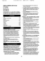
CEPILLADORADE
(15 pulg.)
9:40
PAGE
38mm
Modelo No.
351.226151
Use una cubierta de proteseibnpara el cabello, pars
contener,el cabello largo.
•
•
Use zap_os de sagurided con sueles antideslizantes.
Use gagesde segundad qua cumplan conANSI Z87.1 de
los Estados Unidos.Los espejuelos pars use diario s61o
tien=anI=antesmsistentes al impacto. NO son galas de
saguridad.
Use una m.&scarapare la cars o centre el polvo si la
opemcibn =aspolvorosa.
Est6 agertay pieose claramente.Nunca opera las hermmientes mec_nicas cuando est_ cansado, intoKicado
o cuando estd tomando medicamentos qua producen
somnolencia.
•
PREPARE
Ingles ......................................
2-13
RightFax
•
•
PRECAUClON:
Lea y siga todas las Reglas
de Seguridad y las Instrucciones de Operacibn
antes de usar este producto per primera vez.
21733
•
EL AREA DETRABAJO
PARA LATAREA
Mantenga el _rea de trabajo limpia.Las _reas de trabajo
desordenadas alraen sosidentes.
Ilustracibny Lists de PaRes .....................
Garantia ......................................
14-19
20
No use herramientes
mec_nices en entornos p=aligrosos.
Regles de Seguddad ..........................
20-21
No use herramientas
mec_nicas en lugares
Desempaque ..................................
Montaje ....................................
Instalacibn ..................................
21
21-22
22-24
mojados. No los e_ponga ala nuvia,
Operacibn ..................................
MantenimJento...............................
24-27
27-30
Identificacibnde Prablemas .......................
GARANTIA
COMPLETA
ht,_m=adoso
El _rea de trabajo tiene que center con una iluminacibn
cormct_.
Tiene qua haber un msapt_culo agd*ctricocormcto
disponiblepars la h=arrarnienta.
El enchufe de tms puntas
se debe enchufar dimctamenteen un mospt_culo pars
tres puntas, con=actadoa tierra correctament=a.
Loscordones de eKtensibndeben tenet una punts para la
conexibn s tiarra y los tres cables del cordbn de extensibn
tienen qua sar del calibre correcto.
Mantenge a Ise visites a una distancia segura dag_rea
de trabajo.
Mantenga a los ni6os fuam del lugar de trabajo. Hags
que el taller sea a pruaba de ni6os. Use candados, interruptoms principageso mmueva las Ilavasde los interruptoms pars ev_ar el oso no intencionagde les herrarnt=antes
mec_nicas,
31
DE UN AISle
si fellerseste productoper sause de dotectosen el motenel
en Is mane de ohm en unlabse de unaSo a pa_r de Is
fecha de compm,Sears Io repamr6o memplazar'd,a su
eleceldn, sin costoacidonel.Selielte el Centre de servicio
Sears (1-800-MY-HOME) m,_scercanota rabamddndel
productoo de,,udtvaloal establsc{mientodonde]o adquiri6.
Sieste productose usa pare fines comerdeleso de elquiler,
esta gsrantiaes vdJJdader 90 dies a partlrde Is fecha de
ES NECESARIO
MANTENER
LAS HERRAMIENTAS
cornpm.
•
Estagan_t{s aptica unicamentecusndoel produdcose utilize
en los EstadosLlnidos.
Siempm desenchufela herramienta antes de inspeccionada.
•
Esta garantiale otorgadetacheslegaJesespec_cos y
tambi,'_npuede ustedtener otros detaches quavaden de
estade a estado.
•
Consults el manual pare ver los proosdimientos espec[ficos de mantenimiento y ajuste.
Mantenga le herramienta lubricaday limpia pars Iogmr
uns operacibnm_s segura.
Sears, Roebuck and Co., Dept. 817WA, Hoffman Eotot=as,
iL 60179
•
Remueva les herramientes de ajuste.Adquiera el habito
de r'_t_'isar
pars verificar si se hen rerosvido1asherramientes de ajuste antes de encender Is m_quina.
•
Mantenga redes tas partes listaspara trabajar. Inspeccione ta herramienta pars ver'dicarsi los dispositivosde
proteccibn o si les demt,s partes posden operar correctamente y desernpehar la funci6npars la qua hen side
diseP't
ades.
•
Revise pars verificar si hay partes da5adas. Revise
el alineamiento de las partes movibles, verifique el su
movimiento Be halls restringide,si est_fu'l
rotes, si .re
sobmemontano si existe alguna otto condidbn qua
pueda alectar la operacibnde le herramienta.
Es necesariocarnbiar o reparar correctamente un mecanismo de prc_=accibn
u otra parts qua estd decade. No
haga reparadones provisories.(Use la lists de partes
que se ofmsa para encargar las partes de repuesto.)
ADVERTENCIA; Pars su propia saguridad, lea redes les
reglasy les precauciones antes de opemr la herraralenta.
PRECAUClON: Si=ampresiga los prosadimientosde
op=aracibncorrectos,tagcome se d=afinen=an=ast=a
manual, sun
cuando=ast_familiarizado con 6sta o con otres h=arramientas
pamcidos, Recu=ardequa, agsa descuidaper alquiera una
fraccibn de segundo,pued=asufdr lesiones personagesgraves,
PREPARESE
•
PARA EL TRABAJO
•
Use la mpa adecuada. No usa rope suslta, guant=as,
corbatas, anillos,pulsems, ni otres joyas qua puedan
=angancharsea ias part=asmbviles de la m_quina,
20
RightFax
11/14/2002
APRENDA
•
9:40
PAGE
COMO USAR LA HERRAMIENTA
•
•
•
•
•
•
•
•
•
•
•
•
RightFax
El boise de artfculcode ferreten'aiosluye:
• Perne de cabeza hexagonalde 8-1.25 x 20 rnm (6)
• Perno de cabeza hueca de 6-1.0 x 12 mm (3)
• Perne de cabeza de arandetah_agonal de 6-1.0 x
12 mm (3)
Use la herramienta correcta pars el trabajo. No fuerse la
herramienta ni el acossorio pare haosr an trabajo pars el
qua no hen side disehados.
Dasconecte la herrarnienta cuando cambie las cuchiltas.
•
22/33
Evite qua arranque per accidente.Asegdrese qua el
interrupterestd en la posicibn OFF (apagado) antes de
enchufarla.
No fuerco la herramianta. Funciona n'_,seficienternente
ala velosidad pars la qua rue disehada.
Mantenga las manes alejadas de las partes rnoviblesy
de las superficiescortadoras.
Nunca deje la herramienta desatendida cuando eat6
funcionando.Apague la energ[a el6ctricay no deje la
herrarnientabasra qua pare completamente.
No trete de aicanzar _
de Io posible.Mantenga la
posicibny el equilibrio correctos.
Nunca se pare sabre la herram_enta.Se pueden producir
lesiones graves sita herramiente se inctinaosi usted
entre en eontactocon la cuchilla per accidents.
•
•
•
Tuerca hexagonal de 6-1.0 rnrn (3)
Tuerca hexagonal de 10-1.25 mm (1)
Arandela plans de 6 mm (6)
•
Arandela plans de 8 rnrn(6)
•
•
•
A randelaplane de 10 mm (1)
Arandela de seguridedde 6 rnrn (3)
Tornillode fijacibn de 8-1.25 x 12 rnrn (6)
•
•
AnilloE CMI-11 (4)
Chaveta de 4 x 4 x "10rnrn
•
Indicador de direccibn
IMPORTANTE: La mesa viene revestida con un protector.
Pars gamntizar un ajuste y un funcionarniantocormctos,
retire dicho revestirniento.Este se puede elirninarf_cilrnsnte
rnediante selventes suasas taJescome esencias mineralesy
un pa_e suave. Evlte dejar seer esta solucibnen la pintura o
en cualquierparts de gornao pl_stico.Los solventespueden
deteriorarsates acabados. Use agua y jabbn en la pintura y
an los cornpoosntesde pl_lstico o gems. Despues de lirnpiarLa,cubre todas tas superficiesexpusstas cos una capa I';gera
de acelte, Se recomienda el use de ceraen pasta pare la
parte superior de la mesa.
ADVERTENC|A: Nuosa use solventosrnW vol=ilas. Se
recorniande utilizer solventes no inflamables pars ovltar
pestles incondios.
Conozca su herrarnienta.Aprenda su operecibn, su
apiicacibny sue lirnltacienesespedficas.
Use los acceseriosrecomendados (mfidrase ala p=_gina
15). Si se usen los acosserios incorrectoslas personas
pueden cower el riesgo de tesionarse.
Maneje la plaza de trabajo cormctamenta. Protdjase las
manes centre posibles lesiones.
Apague la rnbquinasi se atasca. La cuchillase atasca si
se introducemuy profundarnenteen la plaza de trabajo
(Is fuerze del motor la rnantiene trebada en la plaza de
trebajo).
Siempre rnantenga los protectores de Latransrnisibn,el
portacuchi[lay la cuchilla an su lugaryen adecuadas
condicionosde funcionarniento,
ADVERTENCIA:
No intentshacer el rnontaje si hay partas
qua faltan. V&lgase de este manual pars solicitarpartes de
repuesto.
Introduzca la pieza de trabajo en la cuchilla o cortador
en seotidocontmrio al de rotacibn.
INSTALACION
PRECAUClON: iPiense an le segurided! La segurided
es una combinacibndel sentido corn,',ndel operador y de
estar alerts en rode memento cuaodo se est_ usando la
herrarnienta.
DE LA CEPILLADORA
Consults la Figure 20, p_gina 18.
Antes de ensamblar la cepilledcra, debe seleccionarse un
lugar adecuado, La cepilladorapesa aproKimadamente
550 re.luego de ser ensarnblada La cepilladoradebe
ensamblarse en el sitiode trebajo.
• Ser_ neossario colocarla cepilledorasobre una superficie
plans y nivelada Esto mejorarf*la estabilidad y exactitud,
Igualrnente,ov_ar8 que se deforrney qua fallen los cornponentesfundidos y las partes soldadas.Ajuste los niveladores de la rn_quina o use calzas seg,',n sea necesario.
ADVERTENClA: No trate de operer la herrarnientahaste
qua est_ completarsente montada seg_n las instruccioos&
Varifique qua no ha,jan ocurrido da_os duranteel eovlo. Si
hay defies, se deber_ presenter un reclamo ala compahfa
de transports.Verifique qua estd complete. Avise inmedietamentea] dlstn'buidorsi faltan partes.
•
Aseg,',resequa hays s_iciente espacie tanto del lade de
alimentacibn come del de saJidade la cepilladorapars
mover Is plaza de trabajo a Io largo de rode la superficie
de corte, Deber_ haber suficienteespacio de rnaneraqua
ni los operadores ni dernn_.s
personas tengan que pararse
en linea con Is rnadera rnientrasse estO usandole hermrnienta.
•
Asirnisrno,ser_ necosario center con una ilurninecibn
edeovada y corrienteek_ctrica (230 voltios)correcta pars
el _bea de trabajo.
Es necesario Iccalizary terrier en cuenta las partes adicionales qua debaR asegurarse a la herramienta antes de
armada:
Le cepilladorase despacha montada, a excopcibn de las
partes siguientes:dos exteosiones de mesa con rodillos,la
rueda de mane, la manivela, el canal de astinas,le varilla de
calibradoresde cuch[ltas,dos calibradoree de cuchiltas,el
boise de art[culosde fermterla, Ilaves de _trerno abierto de
8/10 rnrn y '12/16 mm y Ilaveshexagonales de 3, 4, 5 y 6 rnm.
21
U
!
RightFax
•
11/14/2002
9:40
PAGE
MONTAJE DEL CANAL
Coloque la cepilladoraen el lugar designado para ella. Los
panelas de acceso al motor se hallan en la parte posterior.
La cepilladoraincluye cuatro manivelas rnbvilesque se
deslizan al interim de la base por los lados de alimentacibny salida. Se pueden usar estas mantvelas para
levantar la copilladora y Ilevada a donde sea necasario.
MONTAJE DE LAS EXTENSIONES
DE LA MESA
Monte la extensibn sdere la mesa de la ospilladora por
el lado de alimentanibn usando tres pemos de cabeza
hexagonal de 8-1,25 x 20 mm y arandelasplanas de
8 mm. No apriete los pemce,
AtorniElealas extensiones tres torntUosde fijaci6n de
8-1.25 x 12 ram.
•
•
Cotoque el horde re(toy largo a Io largo de la mesay
las extensiones.
•
RightFax
DE ASTILLAS
Consulte la Figura 19, p_jina 16.
• Partes y artfculosde ferreter[a necosarlos:
Canal de astillas
Pemo de cabeza de arendela hexagonal
de 6-1.0 x 12 mm (3)
Tuerca I'_agonal de 6-1.0 mm (3)
Arandela plana de 6 rnm (6)
Perno de cabeza hosca de 6-1.0 x 12 mm (3)
Arandela de asgurided de 6 mm (3)
• Coloque el canal de astillas asbre la cubierta del
rompeastillas(Clave No. 68) de modo que qosden
alineades las ranuras del canal de astillas y la cubierta
del rompeastillasas[ como las ranuras del canal de
astillasy los orificios de la caja de rodillos.
Consulte la Figura 1,
• Ad.[culosde ferreter[a necosarios:
Pemo de cebeza hexagonal de 8-1.25 x 20 mm (6)
Arandela plana de 8 mm (6)
Tornillode fijaciOnde 8-1.25 x 12 mm (6)
•
23/33
Ajuste el canal de astillas al rompeastillasmedJantetres
pernos de cabeza de arandela, seis arandalas ptanas y
tres tuercas hexagonalea.
Asegure el canal de astillas a la caja de rodillosmediaote
ties pemos de cabeza hueca y arandelas de seguridad.
CONJUNTO
Ajuste los tornillos de fijacibn de rnodoque las extensionesqueden a la misma a_:urade la mesa.
Apriete tos pernos para asegurar la extensibn,
CALIBRADOR
DE CUCHILLAS
Consulte la Figura 2.
• Partes y art[culosde ferreteda cecesarias:
Varilia de calibradorasde cuchillas
Cal_rader de cuchillas(2)
Anillo E 3-CMI 11 (4)
Repita los paros anteriores con la extensidndel lado
de salida.
El conjuntocalibradorde cuchillasse usa para verificar la
a_:urede los hordes de las cuchillasy ajustada seg,',n
sea necosario"
• Deslice el calibradorde cuchillassobre la varilla de
calibredoresde cuchillas.
•
•
•
Coloque el calbrador de cuchillassobre la varilla de rhode
que quede una rnuesca a cade lade del cali_rador.
Optima el anillo E, uno en carla muesca, y asegum la
posicibn del calibradorde cuchillas.
Repita los pasos anteriorascon el otto calibradorde
cuchiHasal otro extremo de la varilla.
Rgura I - MontaJe de les extenslones de la mesa
MONTAJE DE LA RUEDA DE MANO PARA AJUSTE
DE LA ALTURA
_'_'/
Consulte la Figura 19, p_'gina 16.
• Pades y art[culos de ferreteria necesarios:
Ruede de mano
Manivela
Chaveta de 4 x 4 x 10 mm (1)
Arandela plana de 10 mm (1)
Tueros hexagonal de 10-1.25 mm (1)
Indicadorde direccibn (1)
• Coloque la chaveta en el chavetero del eje de transmisi6n
helicoidal(Clave No. 58).
• Desliosla ruede de mano sobre el eje de tmosmisibn
helicoidalde modo que el chavetero qosde alineado
con la chaveta de este eje.
• Daslice el indicedor de direccibnen el eje de transmisibn
helicoidal.Cercibmse de que el indicadorde direccibn
apunte correctamente.
• Use la arandela plana y la tuerca hexagonal para sujetar
ta rueda de rnano al eje de transmisibnhelicoidal.
• Atornillela manivela a la rueda de mano.
de calib_'adoms
de cuchilLas
Aod
Rgura 2 - ConJunto ¢allbrador de _=uchlllas
FUENTE DE ALIMENTACION
Consur:e la Figura 3, p_jina 23.
ADVERTENCIA: No conecte la cepilladom a la fuente
de alimentaci6n hasta haber cumplidotodos los pasas del
eosamblaje.
El motor ha sido dise_ado para funcion_ al voltaje y fmcuencia especifiosdos.Las osrgas normales se pueden manejar
sin riesgce dentro de un intervalodel 10% respecto al voltaje
aspedficado. Si se hace funcionarla unideda un voltaje fuera
22
RiEhtFax
11/14/2002
9:40
PAGE
de este intervalo, se puede recalentar y quernar el motor.Las
cargas pesedas exigen que el voRajeen lostenninales del
motor no see inferioral especificado.
INSTRUCCIONES
PARA LA CONEXlON A TIERRA
ADVERTENCIA:
Si no se conecta correctamente el conduotora [lerra del equipo, se coffe el riesgo de un electrocheque. El equipo debe ester conectado a tlen'a mlentras
se usa,para proteger al operedor de un alectrochoque.
24/33
RightFax
•
Utilice la table pars determinerel tamafio mrnirno dal
alambre (seg,',nla norms A.W.G.) dal cordbn de extensi6n.
•
Utilice ,',nicarnentecordo,-_s de eKtensi6ntrRilaresque
coenten con enchufas ripe conexibn a tierra de tree ctaf,,'ijas y zbcalos tripolareeque funcionen con el ench_e de
la herramienta.
•
Si el eordd,n de extenei6n est_ desgastado, rote o dsr3ado
en cualqulerforma, reempl_oslo inmediatamente.
LONGITUD DEL CORDON DE EXTENSION
Si no comprende las instrucdonas de cone_iOna tlerm o
tiene dudes en cuanto a si la herrarP_nta est', correctamente
conectada a tierre, censure a un aleotricista pmiesional.
A fin de protegerlo centre una desearga ek_otrica,esta herrarelents est;t equipada con un cable de tres conductores
aprabado y clasificadopare 250 V, a_"come con un enchufe
de tree clavijasripe conexibn a Uerra clasificadopare 250 V
(vdese la Figure 3).
No retire ni modifiqueen forms alguna la clarv'ijade conexi_"=
a tierra. En case de un real funcionamientoo unadescornposture, la conexibn a tlerra proporciona una ruts de menor
resistenciapara la descarga el6otrica.
ADVERTENCIA:
AI conectar o descoosctarel enchufe
del z6calo, no permits per ning"n motive que sus dedos
tO<:luenlas d_'ijas.
Tamafio del aiambm
(segOn la norma A.W.G.)
Hasta 50 Nee ..................................
14
AVISO: No se mcomlende utilizer cordcoes de _xtensibn de
rr_s de 15 metros de large (50 pies).
CONEXlONES
ELECTRICAS
CensuRe le Figure 4.
ADVERTENCIA: Un eleotdcistacalificado ddee haosr todas
las ceneodonesal6ctricas. Aseg,',mse de que la unidadestd
apagede y desconectadade la fuente de energia ek_ctrica
mientras monte,conecte o vuelve a conectar el motor o
mientras inspeccioneel cableado.
La cepiRadoratiene un cable de alimeotaci6n aprobadode
230 voltios de tres conductorescon un enchufe tipo conexibn
a tierm de tres clavijas,y un contector magndticode 230
relies que vlene pmcableado de f_rica (vd,ase la Figure4).
Vollaje de
linea de 230
Negro
_erra
Clavija de tierra
Figure 3 -T6cnlose de puesta a tlerra
El enchufe debe coneotarse en el tomecorrieotecorrespondiente de 230 V (vOase la Figure 3) que hays side instalado
y conectado a tierre debidamente_de acuerdo con |odes los
cbdigosy regulaciones locales.No modifiqueel enchufe que
se induye. Si no osbe en el tomecorriente, eolicitea un aleotricistaprotesional que instale un tomacorrienteadecuedo.
Revise periodiosmentelos cordooss de la herramienta;si
est&ndafiados, Ilevalos a un osntro de servicio autorizodo
pare que los reparen.
El conductor verde (o verde y amarillo) del cableee pars
conexibn a tiarra.Si es neossario repararo reernplazar el
cable de alirnentad6n o el enchufe, no conecte el hilo verde
(overde y amarillo) • un terminal con corriente,
Si se cuenta ,',nicamentecon un zbcalo pare dos clavijas,
_ste deber_tser reemptazade con un zl_calopars tres da¢ijas
debidemente conectado s tlerra • instalado de ecuerdo con
las Normas para Instaleciones Ek_otricas(Nalienal Electric
Code) y los cc')digosy regulasionas locales.
ADVERTENClA:
Esta tares deber;t ser realizadaper un
electricista protesional.
CABLES
*Rerra
.../
d_ m_or
Blanco
I
Flje la sabrecarga
Idrrnlca a 18 amp
AI motor
Figure 4- Diagrams de cone(Idn del contactor magndtlco
•
La herramienta tiene un interrupterde bloqueo de Itave
pare ev_ar el use no autorizado.Cuando no se utilicole
herramienta cotoqueel interrupterde bloqueo de ,ave en
la posicibnde OFF (apagado) y retire la ,ave.
AVISO: El motor no arrancar_ei la [lave se encuentra en la
posicibn de OFF (apagado).
DE EXTENSION
El use de cualquler ripe de cordbn de extensibnocasicnar_ una caida en el voRajey una p_,rdidade potencia.
Los alambres dal cordbn de extensk')ndeben tener el
tamafio suficientepara transporter Is corrieoteadecuada
y mantener el voltaje cormoto,
•
23
Conecte la cepilladoraa un circuito de alimentaciOn
protegidoper un cortacircuito de 20 amp o un fusible
de acoibnreterdade.
RightF&x
PROTECCION
11/14/2002
CONTRA
9:40
PAOE
UNA SOBRECARGA
25/33
£ightPax
REGLAS DE SEGURIDAD DE OPERACION
ADVERTENC|A:
El funcionamiento de todas las herrernientas mec&nicaspuede hacer qos sean lanzados e los ejos
cuerpos extra6os, Io cual pueds lesionatos gra,,'emente.
Sier'_oreuse galas de seguridadque cumptancon los requisites de la norrna estadeunidenseANSI Z87,1 (se indica en el
paquete) antes de cornenzara usar la herramienta rnec_'mica.
PRECAUCION: Tenga sismpre en cuenta las sigulentes
precauct
ooss:
El contactorrnagndtion est_ protegido centre una sobrecarga
pare evitar dafios al motor. El protector centre sderecarga
apaga autorn=icamente el contantormagn6tico al ocurriruna
sobrecarga. Fije la sobrecarga t_nnice a 18 amp. Cerci6rese
de desconeotarla cepilladorade la fueote de alirnentaci6n
al reajustar el protector _ontra sd_recarga. El protector se
reajueta abriendo la caja del contaotory oprindendeel
botcW!de reajuste.
VERIFIQUE LAS CONEXlONES
• Enchufe el cable de alimentacibn ale fuents de 230
voltios.
•
Aprenda las reglas de seguridad generales pare el use
de herramlentasmec_nicas,Aseg,',resede comprender
todas las precauciones (v'_aselas p&ginas 20, 21 y 24),
•
•
Lleve la Ilave a Is posicibn de ON (encendido).
Gire y suelte el botbn de pareda.
•
Cuande ajuste e reerr_lase cualquierparte de la sepinadora, abra e[ inten'uptory retire el ench_e de le tuente
de alimentecibn.
•
Pulse el bot6n de arranque. El motor de.Degirar sn
senfide contrarioa las rnanillas del reloj de care al
_xtremo del eje.
Pulse el botbn de parade. El motor debe deteneree.
Pulsar el bot6n de arrenqueya sea con el botbn de
p_ada oprimide o con la liars en la posicibn de OFF
(apsgado) no deber_ porter el motoren maroha.
Si alguno de los pesos s_edores no arroja el resultsdo
espsrado, desconecte la cepilladorade la fuenta de
alirnenfacibn y re,,ise las cons_iones.
•
AsegO.resequelosprotectoresdelportsoJchillayel
rempeastillas est_n coneotamente aonplades y firmernente sujetas.
•
Aseg,',reseque nada abetaculise ninguna parts rncWil.
Siernpre use prctecci6n pare los ojos o pare la care.
Aseg,',resequa las cuchillaseat_n alineadas y correctsmente scoplades al portecuchilla.
No enchufe la cepilladorsa manes qua el interrupterest6
en la posici6n de OFF (apagado). Despuds de encender
et interrupter,perrnita que la ospilladora alcance toda la
velocidad antes de user.
•
•
•
•
Mantenga las manes alejades de las partes mbviles.
No fuerce el carte. Si disminuyela vslocidad o se quads
atascade, se recalientael motor. Perrnitaque le alimenfaci6n autorn_ica funsione correctamente.
DESCRIPClON
Consults las Figures 5-20.
Use rnedera de calidad. Las cuchillas duran m_s y los
cortes resultan m=_suniforrnes si le rnadere es de buena
calidad.
La cepilladora de 15" Craftsman es una unidedde scare
fundido pare use pesede capaz de cepillar madem de heats
15" de ancho y 6" de protundidad.La ospilladom tlene un
di_metre de 3" y un portacuchilla de 3 cuchillascon gates
que facilitanel ajuste y reemplezo de _stas. El portacuchilla
y los rodillos de alirnantanibn se desplazan anbre una base
firme de columnas de acore. Se puede introducirla madera
a razbn de 4.88 5 6.10 m,','dn(16 6 20 pies/min) y se puede
cortar hasta '/." de prnfundidab en cada pase.
La cepillatora vlene con un gabinete cerrade de chapa de
asero seldado que incluye una base r'ndvil,un orifieio de 4"
para le recoleccibnde polvo y un control el6ctrico de segurF
dad con contaotorrnagr_tico. Incluye un motor de re.,olLP
cionee per rninuto de 3 HR
No cepille material cuya Iongitud sea inferiora 1T', cuyo
ancho sea inferior a ¾" ni cuyogrosor sea inferior a 'h".
Nunca copille material cuyo ancho sea mayor de 15" ni
carte a una profundidat mayor de '/o".
Siempre rnantenga losprotectores del portacuchillay la
cuchilla en condicionesadecuadas de funcienamiento.
•
•
ESPEClFICAClONES
•
Tamafio de la mesa .......................
Mesa con =teosiones de redillo ...................
Ancho de cuchilla ..............................
Carte rm!=ximo.....................
Area del susie........................
Correas V ...................................
Oriflcie pars recolecci6n de polvo..........
Motor .............................
20 x 15"/,"
51"
•
15"
V," de protundidad
43'/=x 51 x 31"
Mantenga la proporcibn atecuade entre las superficies
de slimeotecibny satida de la mesa y la trayectoria de
la cuchilladel portacuchilla.
No hags retrocederIs parts hacia la supefficie de
alimenfaci6n de la mesa.
Apoye correctarnenfela pieza de trabajo en rode moments
durenteel foncionanmentey mantengael contr_ de la pate.
Tome las precaucionesneossades en case de contragolpes. No permits qua nadle cruce ni eetO de pie en la
treyectoriade rotacibndel portacuchilla.Los contragelpes
o los residues arrejados ir_men eeta direcci6n.
•
Abra el interreptory descosecte la elimeotacibn si no se
eet_ usando la cepilledere.
• Reemplaco e afile las cuchinassi se ris6an o desefilan.
•Dele mantenimlentoala cepinadera.Siga las instrucciones de rnantanimiento (v4_asslas p_ginas 27-30).
M-60
4" de di_rnetre
3 HI:',3500 RPM
Per copiLlar se entiende reducir el groser de la readers a un
valor deseede al rnisrnotiempo qua se crea une supefficle
nivelada,paralele al lade opueeto de la tabla. Prefundidab
del carte es el tdrrnineutilizadopare re_edreeala protundF
dad ala que las cuchillaspenetran la plaza de trabajo.
PROFUNDIDAD
DI=L CARTE
Consulte las Figures 5 y 19, sn las p_jinas 25 y 16.
Ls protundidaddel carte se ajusta seg,',n le pseicibnde le
mesa con respsctoa las cuchillasdel poriaeuchina. La mese
24
RightFax
11/14/2002
9:40
PAGE
Afloje les pernles de seguridad ("B").
•
Gim la made de mane ("A") pare subir o bajar la rueda de
rnano"
•
Coloqus la mesa en la posicibn deseada.
•
Liave la liars de la ospilladora ala p osici6n de ON (encendido), suef:e el botbn de parada y oprima el botbn de
RightFax
CaJlbradorde la
a]turade oJchlltas
se puede subir o bajar rosdiarlte la rueda de mane (_A").
Para ajustar la profundidad del corte:
•
26/33
Pale
"_
Gate
Cuchilla
Pale
Flgura 6 - AJuste de la altura de lee cuchlllas
arranque.
•
introduzca la madera
per el lade de alimentacibn.
•
Use la graduacibn en las columnes pare medir la profundidad del corte.
•
Sit_s el conjuntocalbrador de cuchillesen el portacuchilla
de mode qua ambes pales del calibrador descansen
firmements sabre el portacuchills.Si es necesario, retire
laplaca deaviadorade estUles (Clave No. 7).
El borde de las cuchillasdabs haosr contactocon la
lengQetadel calibraderde cuchilles.Ajuste la altura de
las cuchil_asgirandoel gale (Clave No. 15).
\
Figure 6 - Prorundldad did oorte
• Pare aumentar la profundidad del corte, suba la mesa;
para reducir la profundidaddel corte, baje la mesa.
• Apriete las perilles de seguridad de la mesa.
• Si cepilla varies piezes de madera, cepille toda la madem
usando los mismos ajustes para reducir uniformementeel
material,
Figure 7 - Verlflcael6n
•
Asegure la cuchillay la curia abretando los tornillosde
curs. Apriste primers los tomillos de cura e_ternos y
prosiga hacia el centre abretando el resto de los tornillos
de cure.
Se incluye un limitadorde la prdundidad del corte (Figure
19, Clave No, 38) para restdngiria profundidad del corte
a un m=_xirnode %'. Nunca haga un corte de cepillado
mayor de V_"de protundidad.
AJUSTE DE ALTURA
de la altura de las euehlllas
Repita los dos pesos anteriores para ajustar la altura
de la mesa al otro extreme de la cuchills.
DE LAS CUCHILLAS
Consults les Figures 6, 7 y 'i9.
PRECAUClON: Les cuchilles de la cepinadorason rnuy
_ilades, Use guantes de cuem pare protagersede lesiones
y tome precaucioi,i,i,i,i,i,i,i,i,i_
_tremes al ajustarlas cuchilles.
ADVERTENClA: Desconecte la cepilladorade la fuente
de alimentadbn antes de hacede ajustes.
•
Repita los pesos antedorescon el taste de les cuchilLes.
Apriete firmaments lodes los torniUosde curs.
•
•
•
Rsemplaos la plesa de_iadora de astillas.
Reemplaos la eubierte det portacuchills.
Reemplaos el canal de estillas.
PREPARACION
•
•
Para obtener una supedicie uniformsen la plaza de trabajo,
los bordes de les cuchillas deben estar a igual distancia del
eje del portacuchilla,La aRura de les cuchillesviene ajustade
de f_orica y no deben'a requedr ajuste.Sin embargo, si es
nacesado realizer ajustes:
• Afloje y _tralga los pemos de cabeza de areodela
hexagonaly los pernos de cabeza hexagonal (Claves
No, 10 y 5) y retire el canal de estilles (Clave No. 69).
• Afloje y e_traiga los pernos de cabeza de arandela
h_agona_ (Clave No` 1O) y la cubierta del rompeestilles
(Clave No. 68).
Aroje loscinco tornillos de cure (Clave No` 14) del
portacuchillapare aflojar la cure del pertacuchina
(Clave No` 13).
25
DE LA PIEZA DETRABAJO
No cepille tables qua estdn sucies. La suciedady piedras
pequeras son abrasivesy desgtL'..'tanla cuchilla.
Elirnine davos y grapes para avitar darer las cuchilles.
•
Evite los nudes. Le fibre sesgade gruesa producenudes
mw duros.Los nudes pueden soltarse y atascar la
cuchilla.
•
La cepilladorafuncionamajor si la madera tlene per Is
menos una superficieplans. Use una cepilladorade
supsdicie o un ospiile mec='micode banco para crear
una supedicie plans.
•
Les tables torcidas o muy combadas pueden atescar la
cepilladora.Rompa la madera en dospara reducir la
magnitud de la combe.
RightF&x
INTRODUCCION
•
11/14/2002
8:40
PAGE
•
DE LA PIEZA DETRABAJO
Introduzce la pieza a Io largo de la '.,eta. Si se introducela
madera an centre de la veta se producen bordes picadce
y astUlados.En algunos ca.sosla veta cembia de dimccibn
a rnitad de la Iongitudde la table. Si as pestle, corte la
table antes de cepillarta (vdase la Figure8).
27/33
RightFax
Repita esta operacidn can todas las tables que deban
tener el rnismo espesor o ajuste la altura.
•
La cepilladora euenta con rodillos de retorno an la parfe
superior de rnodo que el ayudante puede devolverlela
parte al operador.
AVISO: El ayudante tiene qua tornar los rnisrnas precaucionesque el operador.
PROFUNDIDAD
DE CORTE
Consultela Figure 9.
El acabade superficialqua produce la cepilladora as m;_Ls
liso
si la profundidaddel corte utilizade as manor. La profundidad
del limitadorde carte en ',_" indicael valor m_ximo estipulado
pare la prdundidad dal corte.
Conla vala
Rolacldn
Los codes profundosrequieren mayor potenda y les ccasionan mayordesgaste a las parLesde la rnAquina.
Encentrede la v_a
Rotactdn
Vela_
! _
!
m
VEda
I
Corteprofundo
Figure 9 - Prol'undldad de corte
!
i
REDONDEO
Per redandeo se entiende la depresibn de cualquierextrerno
de la tabla producidoper una fuerza desigual del portacuchillacuando la pieza entre o sale de la cepilladora.
I
El redandeo se produce si la table no est_ apoyada adecuademente.Aun estando apoyeda la table se puade
producirun Ugero redondeo.
Una fuerza desigualse genera si un solo rodillode alirnentacibn hace cantacto con la pieza de trabaje al prindpio oal
final del corte.
El redondeoes rn;ts evidenteeuando se hacen cortes rn;ts
profundos.
Pare reducir el redandeo;
Rgura 8 - Dlreccl6n de la veta
PRECAUCION: No nepille una tabla qua tenga menos de
17" de Iongitud, La fuerza del corta puede parfir la table y
producirun centragalpe.
Encienda la cepilladora.
P_rese al lade de la cepilladoraqua tiene acoplade la
rueda de mane para ajuste de altura.
• Suba la pieza de trabajo hasta el rodillode apayo de alimentaci0n sujet_mdolaper los hordes apro_irnadamente
a rnitad de su Iongitud.
• Las tables con una Iongitudmayor de 24" deben recbir
mayor apayo mediante pedestales sblidos independientes
(v_ase Accesorios mcomendados, p_gina 15).
• Haga descansm el eKtrernode la Labiaanbrn el rodillo
de apoyo de alirnentacibny dirfjalahada el interior de
la cepilladora.
• Empuje ligemrnentela t_ola y deje qua ta alirnentacibn
autorn_ticala tome. Suelte la tabla y deje qua la alirnentacibn autorn_ica haga su trabajo. No empuje ni tire
de la pieza de trabajo.
PRECAUClON: No se pare alineado diractarnentecon la
parte antedor o posterior de la nepilladora, Si la cepilladora
e_pulsa un o_jeto, viajar_ an esa direccibn,
• Mu_vase a un lade y recloa la tabla cepillada sujet_,ndola
de la misrnarnanera en que la introdujo.
• No agarre ninguna parte de la tabla qua no haya pasado
per el rodillode apoyo de salid&
•
•
•
•
•
Suavemente Isvanteun poco la table al introducirla
haste que el rodillode salida haga contacto con ella.
Suelte la tabla cuando tanto el rodillode alirnentaalbn
come el de salida estdn en contacto con ella y la table
est'Sya introducidndose.
Mu_vase at lade de salide.
Levantesua,,ernentey soalenga lat abla cuando haya
salido cornpialarnentedel rodillode alimentadbn.
Cuando cepille rn=_sde unatabla, haga qua las tables
se topen entre si pare ev_ar el redondeo.
AJUSTE DE VELOCIDAD DEL SISTEMA
ALIMENTAClON MECANICO
DE
Consultelas Figures 10 y 11 en la p_tgina27.
La velocidad de alimentacibnse refiem ala valocidad a la
qua avanza la madera sobra las cuchilla.s.La cepilladora
de 15" Craltsrnan cuenta con un sialerna de alirnentacibn
mecSnicequa introduceautorr_tieamenta la madera per
debajo del portacuchillade la cepilladora.
26
_ightFax
11/14/2002
9:40
PAGE
El sistema de alimentaci6n mec_nico tiene una caja de
engranajes de dos velocidades pare sepillar maderas tanto
duras come blandas.
Le velocidad beja- 6 pieJrninse usa para maderas duras y la
velocidad alta- 20 pie/rain se usa para maderas blandas.
• Ajuste le velocidad del sistema de alimentacibn mec_nico
mientras est@en funcionamiento la cepilladora.
.,e-----
Pedlla del dslema de
_,llmenlad dn m sc_,nico
28/33
RightFax
•
Si los rodillosse deslizan sobre la pieza, se debe aumentar la tensibn del resarte.
•
Si los rodillosda_an la pieza, se debe reducir la tensibn
del resorte.
•
Ajuste la tensibn del resorte de los rodiIIosde alimentaci6n girandolos tomillos de ajuste (Clave No, 53) a
cada extreme de los mdillos.
•
Aseg0mse de ajustar los tomillos de mode que la tensi6n
del resorte sea igual a embce extremes del rodillo,
Figure 12 -Tensl'_n del rosorte de los rodlllos
Rgura 10 - Perllla del slstema de allmentacldn mec=tnlos
•
•
•
Para engranar Ia velocidad baja de alirnentacibn(16
pies/min), tire de la perilla de velocidades alej_ndola de la
cepiUadera (v6ase la Figure 1"I).
Pare engranar la velocidad alta de alimentacibn(20
pies/min), optima totalmente la perilla de velocidades
acerc_ndela a la cepiUadora(vdase la Figure 11),
ADVERTENClA: Cercibrese de que la unidadeat6
desconectada de la fuente de elimentaci6nantes de
darles mantenimiento a las cuchillas,
VERIFICACION
CUCHILLAS
El sistema de aJime_ad6n mec_nico se puede desengranat Ilevande la perilla de velocidades ala posid6n del
centre o neutro (v6ese la Figure 11 ).
DEL DESGASTE
DE LAS
El estado de las cuchillasafecta la pmcisi6n del corte.
Para verificar el estado de las cuchillas,preste atencibn
ala calidad del corte que produce la cepilladora.
Z
•
•
Las cuchillasdesafiladasreagan, en vez de cortar,
las fibres de madera y dan una apariencia fibrosa,
La veta se elava si las cuchillssdesafiladas golpean
madera de densiciadvariable.
Si las cuchillas tienen piceduras, se e_evan los bordes.
AFILAR LAS CUCHILLAS
Las cuchillasse pueden amolar individualmentecon una
piedra de afUarflna. Cerci6rese de qua la superficlede la
piedra de ace_e sea uniforme y sin desgaste, Para afilar las
cuchillas:
0 mhnin
_ 16_ie/mln
•
Cubra pamialmente
la piedra con papel para proteger la
parte superior de la mesa.
,=1
Rgure 11 - AJuste del elstema de aUmenteel6n mec_nl¢o
•
AJUSTE DETENSION
DEL RESORTE
LOS RODILLOS DE ALIMENTACION
Sit0e la tabla de alirnentaci6n de mode qua la piedra
haga contacto con la cuchilla a Io largo de su superiicie
biselada.
•
Pase la piedra per ambos lades de la cuchilla al mismo
tiempo qua se mueve ligeramente Is piedm en la dimccibn
de alimentaci6n,
DE
Consulte las Figures 12 y 19.
Los rodinosde aiimentecibn y salida (Claves No. 36 y 35)
introducenla pieza de trabajo per debajo del portacuchilla.
Los rodillos de alimentaci6n accionades per resorte ejercen
presibn sobre la pieza de trabajo pare avitar deslizarse.
La tenaibn del resorte de los rodillosde alimentaci6n debe
ser suficientepare av_ar qua los rodillosse deslisen sobre
la pieza de trabajo pete no debeser tanta qua los rodillos
de,an la plaza.
• Cercibrese de pasarla el mismo nOmerode veces per
cada cuchUla.
Si las cuchillasest_n picadas, se deben reemplazar o velvet
a a/ilar, Nunca instalecuchillasdesequilibradas,Afile siempre
las cuchillasen grupos de tres.
AVISO: MuchostaJlems no eaten en capacidad de pulir las
cuchillas,t.as p_ginas amarillasdeben incluirune lista de
"Servicios de a/ilado"o "Amoladura de herramientas".
27
RightFa×
11/!4/2002
REEMPLAZO
9:40
PAGE
DE CUCHILLAS
Retire laplaca desviadora de a_'tillas(Clave No. 7).
Afloje los tom,los de cuSa (Clave No. 14).
Retire cuidadosarnente Is cuchilla.
•
Utopia minuciosarnentelas ranurasdel portscuchilla,las
cu_a.sy los tornillosde cuba.
Introduzcs cuchillasnuevas o atiladas en el portacuchilla.
Reemplace la oJ_a.
Asegure la cuchinaapretando los toreillos de cu_a.
VSase "Ajuste de elture de tss cuchillas"en lap =_lgina25.
•
•
•
•
Elimios t_:lo rnsto de goma y astillas de los retenes seg_ln
sea necesariopare garantizar un funcionamiento segum.
AJUSTE DE LOS RODILLOS
•
•
•
•
Rep,s losseis pesos anteriorosconel resto de las cuchilles.
La teosibn de la correa se debe verificar peribdicamente.
Pare verificarla:Retire los botones y la cubierta de Is
poles (Figurs 19, Claves No. 44y 45).
AjustelatensiOndelacorresgirsndoiachapademontaje
del motor (Figura 20, Clave No` 13). Gire Is chapa aflojando las tuercas he_agonales de] pereo de teosibn (Figure
20, Claves No` 11 y 14) segdn sea necesado.
Le cortes tiene la tensibn cormcta si ellsplicer una ligera
preelbnentre los dedos pulgar • fndice se produce uns
deflexi(_nde ½".
•
•
Cercibmse de qua ambos extrernosde los redillos de
Is mess est@nala rnisma altura de modo que queden
parelelos a 6sts y asegure los ajustadores de excdntrica
rnediante los torniIIosde fijacibn (Clave No. 73).
ConsultsIs Figura 13.
Para realizar elgunos ajustes de reantenimiento es necesado
user un bSoquede sjuste manual (v,_ase la Figure 13).
Hsga este bloque a padir de restos de resdera dura y de
las dimensionesqua se indican.Las dimensiones=actas
no son crucialespete s[ se requiere qua la parte superior
tenga un acabedo rnuysuave y nk,elsdo`
Aseg0rese de volver a instalar los botones y la cubierts
de la polea.
La caja de engranajes de la cepilladom ha sido llenada de
ace[re lubricanteen f_:)dca. El aosite de la caja de engransjesse debe carrlbiar carla 30 horas de funcionareiento`Para
cambiar el aceite:
•
La rnadem de corte _Lsperoreequiereque se ajusten un
p(co rnf,s alto los rod,los reientras que la madera scabada reequiere
que los rodillosqueden un p(co _
bajos.
Pars todo ripe de material y acabado de las piezas de trabajo, los rodi,os de Is mesa se deben situar ligsrarnente
por encirea de la mesa.
La alturade los rodilios de Is mesa se ajustsn aflojando
los tornillosde fijacibn (Clave No`73) y girandolos
ajustadoresde exc_ntrica (Crave No`57).
Coloque una regis sobre la messy los rodillospare
veri'icar el ajuste de estos.
BLOQUE DE AJUSTE
LUBRICACION
•
Vacle el aceite viejo de )a caja de engranajes extrayendo
el tapbn del rondode la caja de engranajes.
Vuelva a colocar el tapcSnde drenaje.
•
Retire el tapbn de Ilenado en la parte superior de la caja
de engranajes.
•
Llene la csja de engranajes con ace_e para engranajes
de grado 50 6 60.
• Wane hasteClUeel nivelde scelte alcenceel orificiodel tapdn.
• Vuelva a col(car el tapbn de Ilenado`
Lubriquefrecuentemente las superficiesdeslizantes de las
colurenascon gmse grat_ada o industrial.
RErENES
DE LA MESA
Consultsla Figure 20, p_gina 1B.
Los rodiUosde la mesa (Clave No` 59) giran libremente para
reducir la friccibny hscer rn=%uniformeel funcionarnientode
la cepmadora.
Ls altura adecuada de los rodiltosde le mesa depende de le
dureza y sce_oadode Is pieza de trabajo;
La altumde los roditlosse debe ajustar de rnodo qua
la pieza de trabsjo avance gradualreentepor la cepilladora sin set daRada pot ellos ni por los rodillosde
alimentacibn.
AJUSTE DE TENSION DE LA CORREA
Consuke las Figures 19 y 20 en las p_ginas 16 y 18.
•
RightFax
Cornpruebe diariamente e! funcionamiento adecuedo
de los retenes anticontragolpe verificsnde que giren
libremente.
Consulte Is Figure 19, p_Jina 16.
PRECAUClON: Las cuchillasde la cepilladorason
_<tremadamente atilades. Utilice guantes de cuero y
tome precauciones al reemplazar las cuchillas.
ADVERTENClA: Desconecte la cepilladera de Is fuente
de alimentacibn antes de reen"plazar las cuchillas.
Si las cuchillasse hen picado o dafiado, deben set reemplazadas. Pare reemplazar cuchillas:
• Retire el canal de astillas (Clave No. 69).
• Retire la cubierta del rompeastillas(Clave No. 68).
•
•
•
29/33
ANTICONTRAGOLPE
Consults la Figura 19, p_gina 16.
Los retenes anticontragolpe (Clays No. 21 ) impiden que
la piezs de trabajo golpee en sentidocontrario el de elirnantacibn. Los retenes deben girar Ibremente pare garantizar
el funcionsmientoseguro de la cepilladore.
Figure 13 - Bloque de aJuste
28
RightF&x
1111412002
9:40
PAOE
AJUSTE
AJUSTE DE ALTURA DEL RODILLO DE SALIDA
Consults las Figures 14, 15, 19 y 20, p_ginsa 29, 16 y 18.
Ajuste [a altura de las cuchillascorrectarr_nte (v6ase
"Ajustede altura de las cuchillas_'en la p_,gina25).
Coloque el bloque de ajuste (Figure 13, p_gina 28) debajo
del portacuchiltaper un extrerno come se mues_raen la
Figura 14. Coloque la I_mina calbradora de 1 mm entre
el bloque y la cuchilla-Suba o baje la mesa de mode qua
la cuchilia apenas haga contactocon la I_u'ninacal_radora
cuando la cuchinaest_ en su posicibnm_ls baja. Ponga la
caja de engranajes en neutro y gire el portacuchilla lentamanta para determiner la posici6n m_s baja de la cuchltla.
Fije le mesa en posicibn apretando lea pedilas de seguridad (Figure 20, Clave No. 75), No destrabe la mesa de
su posici6n ha._a que se hayan ajustado ambos lades
del rodillode alimentacibn.
.
O°
]
•
._/
LaminacaJibradora m
I
I
•
Figure 14- Portacuchllla con bloque
•
•
Retire la I_mina calibradora y deslice el bioquede ajuste
per debajo del rodillode salida (vdase la Figure15).
El rodillode salida debe aponas hacer contactocon el
bloque de ajuste. Si el rodillode salida est_ demasiado
alto o bajo, afloje la tuerca hexagonaldel torniilo de
fijaci6n (Figure ! 9, Claves No, 3 y 29) debajo del rodillo
de salida. Gim el tomillo de fijaci6n para sltuar adecuademanta el rodillode salida. Asegum la posid6n apretando
la tuerca hexagonal del tornillo de fijacibn.
Coloque el bloque de ajuste en el otro _tmmo del rodillo
de salida y repita el paso 4. Cercic'_.se de qua ambos
_trernos del rodille de salida est6n ala miama allure
de mode que quads pamlelo ala mesa.
!
KightFax
DEL ROMPEASTILLAS
Consults las Figures 13, 14, 16, 19 y 20.
El rorrpeastiltas romps las astillas producidas per las
cuchilla-sduranteel cepillado`Luego,el mmpeastillas dirige
les astillas alrededor clelportacuchillay las saca per el canaJ
de astillas.El rompeastillasse debe sltuar 1 mm per debajo
del portacuchillapare funcionar adecuadarnente.
La posici6n del romdeastillasse verificay ajusta aplicando
el siguiente procedimiento:
• gesc_necte la ¢epllladora de la tuente de allmentaclon.
• Ajuste la altura de las cuchillascorrectamente (v_ase
"Ajuste de atturade las cuchillas"en la p_gina 25).
• Coloque el bloque de ajuste (v,Sasela Figure 13, pSgina
28) debajo del portacuchitlaper un extreme come se
muestra en la Figum 14, Coloque la I_,minacal_redora de
1 mm entre el blocluey la cuchilla. Suba o baje la mesa de
mode que la cuchillaapenas haga contactocon la I_nine
calibradoracuando la cuchilla est(_on su posicibn m_s
baja- Ponga la caja de engranajesen neL_my gim el
portacuchilla lentamentepare deterrninarla posicibn m_s
baja de la cuchilla-Fije la mesa en posicibn apmtando
las perillas de seguridad (Figura 20, Clave No. 75). No
destrabe la mesa de su posid6n h_ta que sa hayan
ajustado ambos lades del rompeastltlas.
El rodillode salida (Figura 19, Clave No. 35) se fija en f&brica
de rnodoqua quede 1 mm per debajo de la mesa. No deberfa
sar necesado un mayor ajuste del rodiltode salida pare
se puede vedficar y ajustar aplicande los siguientes
procedimientos:
• _nede
la cepIIladora de la tuente de
allmenta¢16n.
[--
30133
Retire la I_u'ninacalibradoray deslice el bloque de ajuste
per debajo del rompeastillas(vdasa la Figure 16). El
rompeastillasdebe aponas hacer contactocon el bloque
de ajuste.Si el rompeastillasest_ demasiado alto e bajo,
afloje la tuerca h_agonal del tomillode fijaci6n (Figure
19. Claves No. 3 y 29) debajo del mmpeastillas. Gim el
tornille de fijeci6npara situar adecuadamente el rompeastillas.Asegum la posicibn apretando la tuerca
hexagonaldel tornitlode fijaci6n.
Coloque el bloquede ajuste en el ntro extreme deI
rompeaL_'tiltas
y repita el paso 4. Cemibrese de que
ambos extremes del rompeastiIlas est(_nala misma
altura de mode que quede paralelo ala mesa.
Rgura 16 - Rompeastlllas con bloque
1
AJUSTE
DE POSIClON
DE LA MESA
Consulte las Figures 13, 17 y 20.
La mesa viene paralela alpertacuchilla de fd_brica
y no
deben'a sar necesario hacerle mayores ajustes. Si la copiIladoreest_ cottando un lade de la pieza de trabajo m_i_s
profundementeque el otto y rindiendo_sf un corta c6nico,
puede set neceserie ajustarla mesa. Verltiqueque el ajuste
de las cuchillassea el correcto(vdase "Ajustede altura de
las cuchillas"en la p_,gina25),
• Descone_te la cepllladora de la tuente de lllmentecl6n.
L__
Figure 15 - Rodlllo
de sallda son bloque
de aJuste
29
RightFax
•
•
•
11/14/2002
9:40
PAGE
Coloque el bloque de ajuste (v_ase la Figure 13, p_Jins
28.) sobm la mesa per el borde e_terno de la caja de
rodillos en el lade de alimentaci_ de la sepilladora.
Desliosel bl_::luehacia una esquina de la caja de rodillos.
Subs o baje la mesa hasta qua el bloque apenas hags
contacto con la caja de rodillos. Fije la mesa en posicibn
agretando las perillas de seguddad (Clave No. 75). No
destrabe la mesa de su pe_icibn hasta que se hayan
verificado las cuatro esquinas de la caja de rodillos.
Desticeel bloque hecia el otto lado de la cajs de rodillos
en el lade de alimentaci6n de la mesa.Verifique que el
bloque apenas hags contactocon la csja de mdillos,
Muava el bloquede ajuste hacia el lads de s=didade la
mesa y verifique la a[tura de ambos lades de la caja de
rodillos.El boque de ajuste debe apenas hacer contacto
con la caja de rodillos.Si leascuatm esquinas de la caja
de rodillosest_,na igual =dtura, la caja de rodillosy el
portacuchilla est=_m
par=delosala mesa.
Si Is caja de rodillos no est_ par=delaala mesa, se debe
ajustar la mesa. Afloje los dos pernos que sujetan la rueda
dentada de tensi6n de la cadena (v_,ase la Figure !7). Es
posible que sea necesario extrasr el perno "A" pars =diviar
la tensibn de la cadena.
31/33
RightFax
Figure 17 - Abra=adera de tensl6n de la eadena
La altura de la mesa se ajusta retirendola cadena de
las ruedas derltadas de las esquinasy hacidndolasgirar.
Determine cu_,lesquina o curies esquinas requieren ajuste
y retire [a cadena de la rueda dentada de esa esquina. Gire
con la mano la rueda dentada pare ajustar la =dtarade la
mesa (cercibrese de no tocar las demos ruedas).
AVISO: Tsnga la prscaucibnde no girar ninguna rueda
dentada m_s de 1 6 2 dientes.
Gire la(s) rueda(s) dentada(s) haste que la mesa quede
1oarelelaala caja de rodillos.Monte cuidadosamente la
rueda dentade de tensibny tense la cadena adecuadamente.
3O
RightFax
11/14/2002
8:g0
PAGE
32/33
SINTOMA
CAUSAS(S)
La cepiJladerano arranca
1, La Ileveestf_en la posici6nde
OFF (apagade)
2, Botbn de tope oprimido
3,Capinadora sin alirnentaci6n el_ctrica
1. Gire la Ileve ala posici6n de ON (ensendido)
4. Se dispar6 la proteccibn contra
sobrecarga del motor
4_Reajuste el protector centre s_brecarga
det motor; v6ase "Protecci6ncentre una
sebrecarga", p_,gina24
5. Haga qua un electricista cualifiosdevadfique
los interruptoresy las con_xiones
POSlBLE(S)
5. Interruptor o cableado defeotuosos
o sue_os
MEDIDA
RightFax
CORRECTIVA
2. Gim y suelte el bot6n de parade
3. Haga qua un electricista cualificadeverifique
la fuenta de alirnentacibn
Losfusibles o cortacircuitos
se abren con recuenca
1.Motor sobrecargado
1. Reduzca la ca_ja del motor
2, Los fusbles o interruptoresde circuito 2. Haga que inatalenfusibleso cortaclrcuitos
correctos
no tienen la capacidad s_iciente
3.Circuito sobrecargado
3, Reduzca la carga del circuito(apague cuatquier
otto artefaoto)
4, Motor osbleado incorreotamente
4, Haga de nuevolas conexiones del motor
seg,',nel diagrama de altovoltaje mostrade
sebre el motor
El portacuchiltagim en
sentidocontrorio
Motorcableado incorrectamente
Redondeo e_cesivo
(depmsiones al extreme la tabla)
1.Cuchltlas desafiladas
Haga de nL_'VOlaS conexiones del motor seg0n el
diagrama de altovoltaje mostradosobre el motor
1, Reemplace o atile las cuchiltasseg0n lse
inatrucciones;
vdase "Mantenimientd', p_gina 27.
2, Soporte inadecuadopare tables largas 2. Apoye Ise tables largas
3. Presibndesigual del mdino de
3. Ver_ique el funcionamlentodel rodillode
alimentacibn
alimentaci6n
4. Pieze fundide de corte desalineada
4, Verifiqueta posicibn de los tornillosde elevaci6n
5. La madera no eat_ topando
6, Rodillosde apoyo real alineados
5. Haga qua los e_tremos de las piezas de material se topen entre sf a medida que las tables
pasan per la cepilladora
6, Ajoste los rodiUosde apoyo
Veta fbrosa
Cepillade de madera con un alto
contenide de humeded
Seqos la madera pare eliminarsu alto contenide
de hurredad
Veta desgarrada
1.Corte muypesado
2. Las cuchillaseat_tncortandoen
centre de le veta
3. Cuchillas desafiledes
1. Revise "Protundided del corte",p_Jina 24.
2. Reviese "lntroduccibn de la pieza de trabajo",
p_gina 25.
3. Reemplace o atile las cuchillasseg_n I_s
instrucciones;v6ase "Mantenimiento", p_,gina27
',/eta _spera, elevada
1. Cuchillas desafilades
Protundidad del code
dispareja (corte cbnico)
Portacuchillano paralelo ala mesa
Ajuste la mesa; v6ase "Ajustede posici6n de la
mesa", p_gina 29.
Se dealizan las correas
Correas flojas
Tense las cormas; vdase "Ajuste de tensibn de la
correa", p_,gina28.
correotarnent
e
1. Reernplace o afile las cuchillasseg,',n las
instrucciones;v6ase "Mantenirniento", p_gina 27
2.Carte muypesado
2, Revise "Profundided del corte",p_gina 24.
3, Contenido de humeded demasiade alto 3, Sequela madera o use madera seca
31
RightF&x
9:40
11/14/2002
33/33
PAGE
Rightb&x
Your Home
For repair-in
your home-of
all major brand appliances,
lawn and garden equipment, or heating and cooling systems,
no matter who made it, no matter who sold it!
For the replacement parts, accessories and
owner's manuals that you need to do-it-yourself.
For Sears professional installation of home appliances
and items like garage door openers and water heaters.
1-800-4-MY-HOME
Call anytime,
® (1-800-469-4663)
day or night (U.S.A.
www.sears.com
and Canada)
www.sears.ca
Our Home
For repair of carry-in items like vacuums, lawn equipment,
and electronics, call or go on-line for the location of your nearest
Sears Parts & Repair Center.
1-800-488-1222
Call anytime, day or night (U.S.A.
only)
www.sears.com
To purchase a protection agreement on a product serviced by Sears:
1-800-827-6655
(U.S.A.)
Para pedir servicio de reparaci6n
a domicilio, y para ordenar piezas:
1"888"S U-HOGAR _
!
1-800-361-6665
(Canada)
Au Canada pour service en frangais:
1-800-LE-FOYEFP =
(1-888-784-6427)
(1-800-533-6937)
www.sears.ca
® Registered Tradem ads/TM Trademark / aM Sewloe Mads d Sears, Roebuck and Co.
® M area Regist tada / TMMarca de Fdbdca i sMMarca de Sexvicio de Sea_, Roebud_ and Co.
MOMarcpe de commerce / MDM aro_Jed_pos_,e de Sears, Roel_
arid Co.
O Sears, Roebud_ and Co.