1
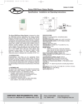
13.0 RETURNING PRODUCTS FOR REPAIR
Before returning the unit for repair, please contact a Setra application engineer (800-257-3872,
978-263-1400) to review information relative to your application . Many times only minor field
adjustments may be necessary. When returning a product to Setra, the unit should be carefully
packaged and shipped prepaid to:
Setra Systems, Inc.
159 Swanson Road
Boxborough, MA 01719-1304
Attn: Repair Department
To assure prompt handling, please refer to return instructions on our Web site at
http://www.setra.com/tra/repairs/cal_rep.htm.
Allow approximately 3 weeks after receipt at Setra for the repair and return of the unit.
Non-warranty repairs will not be made without customer approval and a purchase order to
cover repair charges.
Calibration Services
Setra maintains a complete calibration facility that is traceable to the National Institute of
Standards & Technology (NIST). If you would like to recalibrate or recertify your Setra pressure
transducers or transmitters, please call our Repair Department at 800-257-3872 (978-263-1400)
Model SRPM
Room Pressure Monitor
Installation and Operating Manual
for scheduling.
14.0 WARRANTY AND LIMITATIONS OF LIABILITY
Setra warrants its products to be free from defects in materials and workmanship, subject to the
following terms and conditions:
Without charge, Setra will repair or replace products to be found to be defective in materials or
workmanship within the warranty period; provided that:
a.) the product has not been subjected to abuse, neglect, accident, incorrect wiring not our own,
improper installation or servicing, or use in violation of instructions furnished by Setra;
b.) the product has not been repaired or altered by anyone except SETRA or its authorized service
agencies;
c) the serial number or product code has not been removed, defaced, or otherwise changed; and
d) examination discloses, in the judgement of SETRA, the defect in materials or workmanship
developed under normal installation, use and service;
e) SETRA is notified in advance of and the product is returned to SETRA transportation prepaid.
Unless otherwise specified in a manual or warranty card, or agreed to in a writing signed by a SETRA
officer, SETRA pressure and acceleration products shall be warranted for one year from date of sale.
The foregoing warranty is in lieu of all warranties, express, implied or statutory, including but not
limited to, any implied warranty of merchantability for a particular purpose.
SETRA’s liability for breach of warranty is limited to repair or replacement, or if the goods cannot
be repaired or replaced, to a refund of the purchase price. SETRA’s liability for all other breaches is
limited to a refund of the purchase price. In no instance shall SETRA be liable for incidental or consequential damages arising from a breach of warranty, or from the use or installation of its products.
No representative or person is authorized to give any warranty other than as set out above or to
assume for SETRA any other liability in connection with the sale of its products.
159 Swanson Road, Boxborough, MA 01719,
Tel: 800-257-3872; Fax: 978-264-0292;
Email: [email protected]; Web: www.setra.com
28
SS-SRPM Rev. A 5/1/2008
1
Contents
1.0 Introduction .........................................................................................................5
1.1 Intended Use......................................................................................................................................... 5
1.2 SRPM Function ..................................................................................................................................... 5
2.0 Parts List ...............................................................................................................6
12.0 Electrical
Power
1) Model SRPM-XXXXX-V1-X
For the high voltage model the input voltage range is from 85
VAC to 265 VAC, 50 Hz or 60 Hz
1.1 SRPM Parts List ..................................................................................................................................... 6
1.2 Model SRAN (Option) Parts List...................................................................................................... 6
1.3 Accessories (Option) Parts List ....................................................................................................... 6
All the internal supply voltages are generated using the Switching
Mode Power Supply (SMPS).
Installation Instructions ....................................................................7
All the internal supply voltages and their ratings as follows:
3.0 Mounting and Wiring ........................................................................................9
3.1 Mounting .............................................................................................................................................. 9
3.2 Wiring Electrical box (rough in) .................................................................................................... 9
3.3 Attaching Pressure Tubing ............................................................................................................10
4.0 Model SRAN Room Annunciator Installation ............................................. 11
4.1 Alarm Relay Output ..........................................................................................................................11
4.1.1 Model SRAN Remote Annunciator Wiring ..................................................................11
4.1.2 Non-Setra Remote Annunciator .....................................................................................11
4.2 Audible Alarm.....................................................................................................................................12
5.0 Door Status Switch Wiring ( see Figure 3, J)............................................... 12
5.1 Wiring 12
6.0 Electrical Installation ....................................................................................... 13
6.1 Analog Output (J5) ...........................................................................................................................13
User’s Operating Instructions ....................................................... 15
7.0 Startup and Operation ................................................................................................ 17
7.1 Power-up ..............................................................................................................................................17
7.3 SETUP UNIT SCREEN ........................................................................................ 19
7.3.1 Setup Unit Operation .........................................................................................................19
7.3.2 Entering Data.........................................................................................................................19
7.3.2.1 Password Protection .................................................................................................19
7.3.2.2 Display Averaging .....................................................................................................19
7.3.3 Data Entry Screen.................................................................................................................19
Internal Supply Voltage
+5 V
+3.3 V
+15 V
Max. Current Consumption
800 mA
200 mA
200 mA
2.) Model SRPM-XXXXX-A1-X
For the lower voltage model the input voltage range is from 18 to
32 VAC, 50 Hz or 60 Hz
All the internal supply voltages and their ratings as follows:
Internal Supply Voltage
+5 V
+3.3 V
+15 V
Door Status Switch
Current Consumption
800 mA
200 mA
200 mA
SPDT or SPST NO
7.4 SETUP ROOM SCREEN ..................................................................................... 20
7.4.1 Setup Room Operation ......................................................................................................20
7.4.2 Entering Data.........................................................................................................................20
7.4.3 Data Entry Screen.................................................................................................................20
2
27
Contents (cont’d)
11.0 SRPM Specifications
Performance Data
Accuracy RSS* (at constant temp.)
Non-Linearity (Terminal Method)
(BSSL Based)
Hysteresis
Non-Repeatability
Zero Setting Tolerance
Span Setting Tolerance
±0.5%
±0.35%
±0.25%
±0.05%
±0.05%
±0.5% FS
±0.5% FS
Thermal Effects**
Compensated Range °F (°C)
±0.03% FS (±0.05% FS)
Overpressure
±1 psi
* RSS of Non-Linearity, Non-Repeatability and Hysteresis
**Units calibrated at nominal 70°F. Maximum thermal error computed from this datum.
Environment Data
Temperature
Operating* °F (°C)
Storage °F (°C)
Operating Humidity
*Operating temperature limits of the electronics only.
+32 to 120 (0 to +50
-20 to +160 (-30 to ±70)
5 to 95% RH (Non-condensing)
Physical Description
Case
Dimensions
Electrical Connection
Pressure fittings
Weight (approx.)
Mounting
Display
LCD
Status Indicators
Fire Retardant Plastic (NEMA 1 Rated for Indoor Applications)
8”H x 5.4”W x 1/8”D
(20.3H x 13.7W x 4.1D cm)
Removable Terminal Block
Barbed Fittings for 1/4” Tubing
1.5 lbs (680g)
(Mounts to double gang electrical box.)
7.5 SETUP ALARM SCREEN
.............................................................. 21
7.5.1 Alarm Setup Operation ......................................................................................................21
7.5.2 Entering Data.........................................................................................................................21
7.5.2.1 Mute Time Out/Alarm Delay ..................................................................................21
7.5.3 Data Entry Screen.................................................................................................................21
7.6 SELF TEST SCREEN............................................................................................ 22
7.6.1 Self Test Operation ..............................................................................................................22
7.7 CALIBRATION SCREEN ............................................................................22
7.7.1 Calibration ..............................................................................................................................22
8.8 Pressure Monitoring Screens ................................................................23
9.0 Maintenance ...........................................................................................25
9.1 Cleaning ..................................................................................................25
10.0 Agency Electrical Standards ................................................................25
11.0 SRPM Specifications ...........................................................................26
12.0 Electrical ................................................................................................27
13.0 RETURNING PRODUCTS FOR REPAIR ..................................................28
14.0 Warranty and Limitations of Liability .................................................28
128 x 128, RGB Backlit
Green LED, Normal; Red LED, Alarm; Backlit LCD
Electrical Data (Voltage)
Circuit
Output*
3-Wire (Exc., Out, Com)
0 to 5 VDC
0 to 10 VDC
Excitation
Code V1
Code A1
Power Consumption
Alarm Output
85-265 VAC, 50-60 Hz
18- 32 VAC, 50-60 HZ
5W
SPDT Relay
1A @24 VDC
1A @ 120 VAC
*Calibrated into a 50K ohm load, operable into a 5000 ohm load or greater.
Electrical Data (Current)
Circuit
Output
External Load
Excitation
Code V1
Code A1
Pressure Media
26
2-Wire
4 to 20 mA
0 to 510 ohms
85-265 VAC, 50-60 Hz
18- 32 VAC, 50-60 HZ
Air or Nonconductive, Nonexplosive Gases.
3
9.0 Maintenance
The SRPM is designed to operate in an indoor environment, monitoring clean, dry (see humidity specifications) air.
9.1 Cleaning
Important
Do not blow into the pressure tubing or fittings with mouth. Compressed air, or
canned air. Such actions may permanently damage the pressure sensor.
Cleaning your SRPM
Do not clean or wash-down the SRPM with industrial cleaners or solvents. The
housing may be wiped down with soap and water or isopropyl alcohol; and, the
LCD display with isopropyl alcohol only. Do not immerse unit.
!
For 120/240 VAC Version, only
CAUTION: Do not open or remove SRPM cover (tool required) with
input power applied unless performed by a licensed electrician.
“Hazardous Live” voltage is present at connector J3 when power is
applied. Please observe the warning symbol ( ! ) near the J3 power
connector.
10.0 Agency Electrical Standards
This device falls into CSA “Pollution Degree 2” for pcb insulation and CSA “Installation Category 2”.
The SRPM meets the following requirements:
General Requirements - Canadian Electrical code
CSA Standard C22.2 No 0-M 91
CAN/CSA C22.2 No. 0.4-04
CAN/CSA-C22.2 No. 61010-1-04
ANSI/UL61010-1 (Second Edition)
4
Figure 1: Typical Installation
-General Requirements - Canadian electrical code, Part 1
-Bonding of Electrical Equipment
-Safety requirements for electrical equipment for measurement, control and laboratory Use Part-1: General Requirements
-Safety requirements for electrical equipment for measurement, control and
laboratory Use Part-1:
25
7.0 Model SRAN Remote Annunciator
Setra’s Remote Annunciator (SRAN) provides remote indication of
room status.
Audible
Alarm
Green LED
Red LED
Acknowledge
Switch
1.0 Introduction
Congratulations, and thank you for purchasing Setra’s Room Pressure Monitor
(Model SRPM). Its ease of operation and durable construction will provide years
of reliable service. While the SRPM is easy to operate, it is advisable to read this
guide carefully before use. It is designed to help you take full advantage of the
function and performance of the SRPM.
1.1 Intended Use
The SRPM is designed to monitor critical air environments, providing room static
pressure indication, alarming, and communication functions. The applications
include:
1.) hospitals - patient isolation and protection rooms, operating suites,
intensive care and emergency rooms.
2.) pharmaceutical, semiconductor, and precision
manufacturing and clean rooms.
3.) laboratories - medical research and BSLs (Bio-Safety Labs),
radiation, toxic metals and chemicals.
Green LED
Visual indication of normal room
condition
Red LED
Visual Indication of a breach in room
pressure protection.
Audible Alarm
Buzzer sounds to indicate a breach in
room pressure protection
Acknowledge Switch
Press to Silence the buzzer.
1.2 SRPM Function
The SRPM senses very low differential pressure using Setra’s patented, high accuracy capacitive sensor technology. The pressure difference for these application
is the difference in static pressure between a critical environment room and its
surrounding reference area ( usually a hallway or another room) see Figure 1.
Maintaining and monitoring a static room pressure difference insures that the
critical environment room is either protected or isolated from a surrounding
environment. Protection strategy requires a net positive room static pressure
difference, while isolation requires a net negative static pressure difference. The
SRPM can be programmed to monitor either positive or negative room static
pressure. The SRPM low pressure sensing technology is coupled with multifunctional alarming and simple, intuitive touch-screen user interface with selectable
security protection.
Operation
Under normal conditions the Green LED remains on. When an alarmed condition
occurs (i.e., room pressure falls outside preset range), a signal is triggered by the
SRPM, the Green LED shuts off, the Red LED flashes and the Audible Alarm sounds.
The acknowledge button can be pressed to momentarily turn-off the Audible
Alarm and the Red LED will continue to flash until the alarmed condition is corrected. When the alarmed condition is corrected the annunciator will reset itself.
The Green LED will turn-on, the Red LED and Audible alarm will shut-off.
24
5
8.8 Pressure Monitoring Screens
2.0 Parts List
The actual room static pressure is shown as a number on the LCD and visually as
a “Moving Bar” indicator operating between the preset pressure limits.
1.1 SRPM Parts List
Normal room pressure condition within the preset pressure limits is verified by a
Green colored screen
Qty
(1)
(2)
(2)
(4)
Setra SRPM assembly
Barbed Coupling, Brass
1/4 inch Tube, Silicone, Inter-Connect
6-32 x 1/2” Mounting Screws for SRPM Base
Not Included: Supplied by User
(2)
Single Gang Electrical Box for RPS Plates
(1)
Double Gang Metal Electrical Box with Grounding
Stud
(1)
4 x 4 inch Metal Plaster Ring
(1)
Door Switch SPDT or SPST, N.O., as needed
1.2 Model SRAN (Option) Parts List
Qty
(1)
Green Screen
Normal
Normal room pressure condition within limits turns screen to yellow when door
is open, indicating “Pre-alarm”.
Annunciator Assembly
Not Included: Supplied by User
(1)
Single Gang Electrical Box
Yellow Screen
Pre-Alarm
1.3 Accessories (Option) Parts List
Qty
(2)
Part # RPS, Static Pressure Fitting Plate
Not Included, Supplied by User
(2)
Single Gang Electrical box for RPS Plates
Room static pressure outside preset limits is indicated by a Red screen after expiration of alarm “time delay”.
Red Screen
Alarmed
6
23
7.6 SELF TEST SCREEN
Press to Access Screen
Installation Instructions
7.6.1 Self Test Operation
This screen identifies the Product Model and Software Version. User can also perform a Self Test of
the SRPM to verify that the data in memory hasn’t
been corrupted and also test the alarm to verify the
sound level and alarm setup.
Press “Power On Self Test” button to initiate test
sequence.
Press “Test Alarm” to test buzzer and visual Red LED
Alarm.
Press “Exit” to return to Main Menu.
7.7. CALIBRATION SCREEN
Press to Access Screen
7.7.1 Calibration
Perform a simple two-step, key tap calibration
process. To re-zero the device, disconnect the “room
pressure” tube and lightly press (or tap) the “Zero”
button. Then apply a steady full scale pressure signal
to the “+” or “room pressure” tube or fitting and
press (or tap) the “Span” button. Reconnect the room
pressure tube and calibration is complete. Calibration
must be within + or - 5% of original calibration. The
original factory pressure calibration can be restored,
if desired, by pushing the “Restore Factory Setting”
button.
22
Note: The SRPM pressure header plugs into the Setra Model 869
Expert System Calibrator for quick and secure automatic calibration. Exit to return to main menu, then press the “back key” to
enter normal monitor mode.
7
7.5 SETUP ALARM SCREEN
Press to Access Screen
The user can:
a.) Latched Alarm requires the pressure to return to
normal and be acknowledged before alarm can be
“Silenced” and “Reset”.
b.) Enable the audible alarm “Yes” or use visual only alarm
“No” signaling
c.) Provide a door “open” pre-alarm visual indication.
When activated the door status “open” condition is indicated by the touch screen display turning from green to
yellow, and door open indicated on Default Screen.
d.) Set the time in seconds that the alarm can be silenced
in the latched alarm mode before the alarm resumes.
This assumes that the room static pressure is still outside
the normal or set operating limits. The Mute Time Out
can be set from 0 to 60 seconds.
e.) Set the Alarm Delay in seconds from the time that
the room pressure goes out of the preset limits until the
alarm activates. The alarm delay may be set from 0 to 60
seconds.
f.) Set the alarm volume or sound level. Using the Up and
Down keys, the volume can bet set at level 1-4. Level 4
alarm volume is the loudest and corresponds to a sound
level of 85 db at a distance of 4 inches.
7.5.1 Alarm Setup Operation
Lightly Press (or tap) button to select “Yes” or No” for
Latch Alarm, Audible alarm, or Door Alarm Input . Selected box background will change from clear to black.
7.5.2 Entering Data
7.5.2.1 Mute Time Out/Alarm Delay
7.5.3 Data Entry Screen
Pressing (or tapping) the “Mute Time Out” or “Alarm
Delay” box activates the “Data Entry” screen (see 7.5.3) to
set the time.
Enter numbers by pressing each key in sequence until the desired character is displayed in
the data entry box above the keypad. (Note: The cursor will blink for one to two seconds then
stop and display the character.) Erase any mistakes by using the “Back Space” key. When finished entering data, “Press Enter” key and return to SETUP UNIT screen, press “Save and Exit”
to return to MAIN MENU, then press “Back” to return to PRESSURE MONITORING SCREEN.
Example:
Enter number 3, press (or tap) 3/DEF key once
Enter the letter T, press (or tap) the 8/STU key three times in succession.
8
Figure 2: Location of Components and Accessories
Note: Use the eraser end of a pencil or back-end of a pen to press (or tap) box on screen to
increase accuracy of inputs.
21
7.4 SETUP ROOM SCREEN
3.0 Mounting and Wiring
3.1 Mounting
Press to Access Screen
7.4.1 Setup Room Operation
Monitor either “protective” positive room static
pressure or “isolating” negative room static
pressure.
7.4.2 Entering Data
Press lightly or tap Positive Room or Negative
Room button. Background of selection will
change from clear to black, then enter high
and low limits as follows:.
Simply press lightly (or tap) either the “Positive
Room” or “Negative Room” box to activate the
“Data Entry Screen” (see 7.4.3.), then proceed to
enter the low and high limits of the room pressure to be monitored. Save and Exit.
7.4.3 Data Entry Screen
Enter numbers by pressing each key in sequence
until the desired character is displayed in the data
entry box above the keypad. (Note: The cursor will
blink for one to two seconds then stop and display the
character.) Erase any mistakes by using the “Back
Space” key. When finished entering data, “Press Enter” key to return to SETUP UNIT screen, press “Save
and Exit” to return to MAIN MENU, then press “Back”
to return to PRESSURE MONITORING SCREEN.
Example:
Enter number 3, press (or tap) 3/DEF key once
Enter the letter T, press (or tap) the 8/STU key three times in succession.
Note: Use the eraser end of a pencil or back-end of a pen to press (or tap) box on screen to
increase accuracy of inputs.
.
20
For 120/240 VAC Version, only
!
CAUTION: Do not open or remove SRPM cover (tool required) with input
power applied unless performed by a licensed electrician. “Hazardous Live” voltage
is present at connector J3 when power is applied. Please observe the warning
symbol ( ! ) near the J3 power connector.
The Setra Room Pressure Monitor is designed to be mounted on a standard
double gang metal electrical box using a 4 x 4 inch plaster ring adaptor.
Remove the SRPM cover and mount the baseplate to the plaster ring adaptor
using (4) 6-32 1/2 inch long mounting screws, see Figure 2. Note: The plaster
ring external mounting face needs to be positioned flush to recessed, relative
to the surface of the wall. Also note the orientation of the 4 mounting screws in
the plaster ring, the plaster ring is rotated 90° from conventional mounting.
Electrical Box
4 x 4 inch Plaster Ring
(Rotated 90°)
SRPM Metal Base
SRPM Cover
Figure 3: Mounting the SRPM
3.2 Wiring Electrical box (rough in)
Pre-wire electrical box with power (24 VAC or
120/240 VAC depending on SRPM model ),
and provide grounding to the electrical box
and plaster ring adaptor. Note: For CSA Safety
Certification it is necessary to ground the metal
electrical box to building earth ground. The
safety ground path consists of the (4) 6-32
x 1/2” metal screws that connect the RPM
metal base to the 4” x 4” metal plaster ring. The
plaster ring is grounded to the 4” x 4” electrical
box Mounting Screws (x2)
by 2 mounting screws.
Figure 4: 4” x 4” Electrical Box
Power leads and wiring should be 14 to 22 AWG braided wire. 18 AWG braided
wire is recommended for wiring J3 power connector to SRPM (see J3, Figure 2).
For 120/240 VAC the hot wire connects to H and neutral to L.
9
7.3 SETUP UNIT SCREEN
3.3 Attaching Pressure Tubing
Typically a Room Pressure Snubber (RPS) is
installed in the monitored room. Attach pressure
tubing as follows:
1. ) Connect the 1/4 inch O. D. tubing (Figure 5)
from the RPS to the 4” x 4” electrical box for the
SRPM by pushing the 1/4 inch tube onto one end
of the barbed, male to male, tube adaptor, then
push the silicone tube (supplied) onto the other
end (see Figure 6). Thread the tubes, with installed
adaptor, through the conduit opening at the bottom of the electrical box (see Figure 7).
2. ) Next push the open end of the silicone tubing onto the removable SRPM header (H1), port
labeled “+”(see Figure 7).
Press to Access Screen
7.3.1 Setup Unit Operation
Press (or tap) button to select an output or engineering unit. Selected button background will change from
clear to black.
1/4” O.D.
Tubing
7.3.2 Entering Data
7.3.2.1 Password Protection
Lightly pressing (or tapping) the
“Yes” button activates the “Data
Entry Screen” (see 7.3.3 to enter
your password. ) Enter password,
then press “Enter”. “Password Setting Screen” will pop-up, enter new
password, enter password again to
Password Setting Screen
confirm, then press “Save”.
(See MENU TREE, page 16 for password entry operation.)
Figure 5: Room Pressure
Snubber (RPS)
Note: The header is an Electro-Pneumatic (EP)
assembly. “+” indicates (Positive) pressure, and “-”
indicates (Negative or Reference) pressure.
3. ) For the most pressure stable operation an
RPS installed in the reference pressure area is also
recommended. In this case, install the RPS in a hallway or anteroom. Plumb to the SRPM in the same
way as “+” pressure, except plumb the tube to the
“-” port on Header H1. Tighten swivel
fittings on the EP assembly if they become loose.
Figure 6: Silicone & RPS Tubing
connected by barbed Male to
Male Tubing Adaptor
7.3.2.2 Display Averaging
Lightly pressing (or tapping) the box activates the
“Data Entry Screen” (see 7.3.3). Enter from 0 to 60
seconds. Display averaging affects the analog output.
Increase display averaging time to “Smooth” the pressure readings.
Electrical Box
7.3.3 Data Entry Screen
Enter letters or numbers by pressing each key in
sequence until the desired character is displayed in
the data entry box above the keypad. (Note: The cursor
will blink for one to two seconds then stop and display
the character.) Erase any mistakes by using the “Back
Space” key. When finished entering data, “Press Enter”
key to return to SETUP UNIT screen, press “Save and
Exit” to return to MAIN MENU, then press “Back” to
return to PRESSURE MONITORING SCREEN.
Silicone Tubing
RPS Tubing
SRPM Header H1
10
Figure 7: Example of
Completed Tube Installation
Example:
Enter number 3, press (or tap) 3/DEF key once.
Enter the letter T, press (or tap) the 8/STU key three times in succession.
Note: Use the eraser end of a pencil or back-end of a pen to press (or tap) box on screen to
.increase accuracy of inputs.
19
7.2 MAIN MENU SCREEN
4.0 Model SRAN Room Annunciator Installation
4.1 Alarm Relay Output
The Single Pole Double Throw (SPDT) relay output can be used for remote signaling of alarm condition. A form “C” contact rated at 1A is available. Connect to J4,
Pins 1 and 4.
4.1.1 Model SRAN Remote Annunciator Wiring
(see Figure 8 below or Figure 2, pg. 8)
Remote Annunciator Connector (J1), SRPM Connector J4:
Connect pins 1 & 2 (short) and then connect pin 2 (+15 V Exc.), pin 3
(Ground, pin 4 (Annunciator Trigger).
J4: SRPM
J1: SRAN
P4 (Annunciator Trigger
+15 VDC Excitation A1
P3 (Ground)
Ground A2
P2 (+15 VDC Excitation)
+15 VDC Trigger A3
Jumper
Button
Description
Setup Unit
Setup password, output, engineering
units, and display averaging
Setup Room
Setup high and low pressure limits to
monitor positive or negative room
Setup Alarm
Setup latch alarm, audible alarm, door
alarm input, mute time out, alarm delay,
and volume
Self Test
Identifies product model and software version.
Verifies SRPM operation and alarm sound level
and setup
Calibration
Perform zero and span calibration
Back
Returns to monitoring screen
P1 (Relay N.O.)
Figure 8: Model SRAN Wiring
4.1.2 Non-Setra Remote Annunciator
The SRPM can drive other annunciators that are powered by a 15V supply, 50 mA max., and accept a 15V trigger. If purchased separately, the
SRAN can also be driven as shown in Figure 9.
J1
Power Supply
15 VDC
–
+15 VDC Excitation A1
Ground A2
+15 VDC Trigger A3
+
N.O. (Alarm)
N.C.
(No Alarm)
Figure 9: Remote Annunciator Wiring
18
11
4.2 Audible Alarm
Alarm potentiometer adjusts from 0 to 85 dBA. Using a screwdriver, rotate
potentiometer clockwise to increase volume and counterclockwise to decrease
volume.
7.0 Startup and Operation
The SRPM is designed with an easy to use touchscreen interface. In its normal state the “Monitoring Screen” displays the actual room static pressure..
The buttons at the bottom of the screen give you access to the functions
that can be performed.
7.1 Power-up
Apply power to the SRPM and observe the welcome screen and subsequent
transmission to the pressure monitor screen.
J1
Audible Alarm
Potentiometer
J2
Figure 10: Model SRAN
PC Board View
Welcome Screen
5.0 Door Status Switch Wiring ( see Figure 2, J6)
5.1 Wiring
Use normally open (N.O.) side of contact switch. The RPM will indicate status of
door position. A contact closure indicates that the door is closed. This is a low
voltage circuit (5 VDC).
Monitoring Screen
The actual room static pressure is shown as a number on the LCD and visually as
a “Moving Bar” indicator operating between the preset alarm units. The “Vertical
Bar” is an indicator of the pressure.
12
Button
Description
Silence
Menu
Reset
Shuts off Alarm
Access to setup functions
Resets the unit in “Latched” mode. See Alarm Setup
Screen.
17
16
LOGIN
Menu Tree
(Shown with Password Entry)
No
No
Yes
Pressure is normal, the
screen is Green
4
10 Secs
Down
Cancel
Up
30 Secs
Calibration Screen
Apply Parameters or
“Restore Factory Setting”.
Apply Zero
ZERO
Pressure
Apply Full Scale SPAN
Pressure
Restore
Exit Factory Setting
-0.026 “WC
Negative Room
-0.02
Reset
Menu
Reset
-0.04
Pressure falls outside of
preset limits (alarmed state),
the screen is Red
-0.02
Silence
-0.04
Pressure is normal and door is
open, the screen is Yellow
Menu
–0.001” WC
Silence
Back
Calibration
Self Test
Setup Alarm
Setup Room
CALIBRATION
MENU
–0.021” WC
Door Open
MENU
Setup Unit
Main Menu
Screen
Negative Room
Alarm Setup Screen
Enter Parameters
Select “Save” to exit.
Save & Exit
Volume
Alarm Delay
Mute Time Out
Door Alarm Input Yes
No
Yes
Audible alarm
Password
Entered
Correctly
Negative Room
Door Open
Cancel
MENU
SETUP
ALARM
OK
Latch Alarm
Normal, Warning, and Alarm Condition Screens
Enter Parameters
Select “Save” to exit.
Setup Room Screen
Setup Unit Screen
Enter Parameters
Select “Save” to exit.
Data Entry Sreen
Login Sreen
Cancel
LOGIN
Enter Password
User!
Password Not
Entered Correctly
LOGIN
OK
Cancel
Wrong Password
Entered, Re-enter
the Password
OK
Enter Password
Usr!
Enter Password
Wrong password
entered or Number
of Tries Exceed the
Maximum Number
of Tries. Return to
Pressure Monitoring
Screen
Pressure Monitoring
Screen
Menu Button Pressed
WelcomeScreen
Self Test Screen
Test Alarm
6.0 Electrical Installation
6.1 Analog Output (J5)
SRPM can be configured as current (4 to 20 mA) or voltage (0 to 5 or 0 to 10 VDC).
Voltage output pin 1, Current output pin 2, Common pin 3. Note. No external
excitation is required.
1 V Out 0 to 5, 0 to 10 VDC
2 C Out 4 to 20 mA
3 Common
Figure 11: Analog Output (J5)
13
User’s Operating Instructions
14
15