1
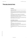
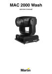
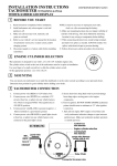
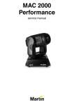
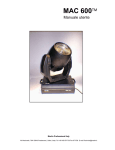
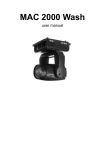
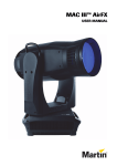
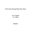
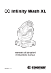
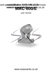
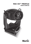
Martin University
MAC 2000 Service
ADJUSTMENT
OPTIC PATH
•
•
•
•
•
•
•
•
•
•
•
•
•
•
•
•
•
•
•
•
•
•
Reflector
Lamp
Heat filters
Dimmer L
Dimmer R
Magenta x
Magenta y
Cyan y
Cyan x
Yellow x
Yellow y
CTC y
CTC x
Diffusion filter
Color/effect wheel
Gobo wheel 1
Gobo wheel 2
Iris
Effect wheel
Focus
Zoom
Front lens
Gobo wheel #2
Gobo wheel #1
Magenta “X”
Cyan “Y”
Yellow “X”
CTC “Y”
Front lens
Zoom
Focus
Dimmer R
Dimmer L
Heatfilters
Lamp
Reflector
Effect wheel
© 2000 Martin Professional A/S, Denmark
Iris
Color / effect wheel
Diffusion filter
Magenta “Y”
Cyan “X”
Yellow “Y”
CTC “X”
Adjustment Procedures
1
Martin University
MAC 2000 Service
DIMMER
NOTE: The dimmer plates must always be installed with the reflective side facing the
lamp. The black side must point away from the lamp.
INSTALLATION
Place the first (right) dimmer plate on the top motor and the second (left) on the bottom
motor.
ADJUSTMENT
1
Set the dimmer to the closed position either by resetting the fixture or by selecting
UTIL > Adj > HEAd > dIM > CLOS.
2
Position the right dimmer plate so that there are 1.5 mm between the black side of the
dimmer and the module plate.
3
Loosely hold a round 2.2 mm spacer, such as a drill bit, between the dimmer blade and
the mechanical stop while pressing the dimmer towards the stop, and allow the
adjustment tool to roll/slide to its "trapped" position. Tighten the set screw.
4
Position the left dimmer plate so that there are 3.75 mm between the black side of the
dimmer and the module plate.
5
Repeat step 3 for the left dimmer plate.
6
Verify that the dimmer plates are parallel and cannot collide. Reset the fixture and
check the adjustment.
CALIBRATION
© 2000 Martin Professional A/S, Denmark
To calibrate the dimmer, select UTI L/C AL/ D O F and press [Enter]. Hold a piece of
paper over the lens. Set the offset to 0 and then increase it until light is clearly projected
onto the paper. Press [Enter] to save the setting. Remove the paper.
Adjustment Procedures
2
Martin University
MAC 2000 Service
CMYC
Opening the CMYC module
CMY module #2
Cyan “X”
Magenta “Y”
CTC “Y”
CMY module #1
Yellow “Y”
CTC “X”
Cyan “Y”
Magenta “X”
Yellow “X”
© 2000 Martin Professional A/S, Denmark
CMYC flag order and orientation
Adjustment Procedures
3
Martin University
MAC 2000 Service
INSTALLATION
Important!
The x and y filters must be installed with the coated sides facing each
other and in the order shown above.
Snap the idle rail into the module. Place a pair of color filters on the drive rail with the
coated sides facing each other. (“Pat. Pending” reads true on the coated side.)
Magenta and CTC: Clamp the drive belt to the inside slot of the Y slide. The clip teeth
must face the belt teeth. Work the belt under the bottom filter slide. (Figures A and B).
Cyan and yellow: Clamp the drive belt to the inside slot of the X slide, the one opposite
that shown in Figures A and B, below. The clip teeth must face the belt teeth. Work the belt
under the bottom filter slide.
All: Place the small slides on the idle rail (Figure C) and rest the drive rail over the clips.
Verify that the top filter is over the bottom filter, then snap the drive rail into the clips
(Figure D).
If the drive gear has been removed, place it on the motor shaft and leave the set screw
loose.
On fixtures without a spring tensioning system for the belts (before S/N 414847-0001),
remove the idle pulley to avoid damaging the belt when you mount it. On later fixtures, just
move the pully towards the middle. Guide the belt around the drive gear, through both
outer belt slots, and around the idle pulley (Figure E). On older fixtures, mount the idle
pulley on the module (Figure F).
Center the drive pulley on the belt and tighten the set screw.
A
B
D
C
E
F
© 2000 Martin Professional A/S, Denmark
Installation of CTC filters on fixtures without belt tensioning mechanism. Installation of other colors is similar but
the belt is first clamped to the X filter when installing cyan and yellow.
Optical order
Installation order
Color
X filter
Y filter
X filter
Y filter
Magenta
1
2
bottom
top
Cyan
4
3
top
bottom
Yellow
5
6
top
bottom
CTC (orange)
8
7
bottom
top
Adjustment Procedures
4
Martin University
MAC 2000 Service
ADJUSTMENT
Important!
The CMYC module is adjusted without power to the motors.
Slide the two color filters away from the center and position them with equal distance
between the large slide and the rail holder on each side. The distance is not important as
long as it is exactly the same for both filters (Figure A).
Clamp the drive belt to the outer slot of the bottom filter (Figure B).
Verify that the color filters move in opposite directions when turning the drive pulley
(Figure C).
Slide the filters all the way out. At the point where the micro switch is activated, verify that
there is a clearance of approximately 1mm between the large slide and the clip for the drive
rail. (Figure D)
A
A
A
B
Arrange the filters with equal distance between the slide an the
clip for the drive rail.
Clamp the belt in the outer slot.
1 mm
1 mm
C
D
Verify that the filters move in opposite directions when you turn
the motor pulley.
Verify that their is approximately 1 mm clearance at the slides
when the filter activates the switch.
© 2000 Martin Professional A/S, Denmark
CALIBRATION
Color mixing can be calibrated to match a reference fixture. Project white beams with no
dimming and position them for easy comparison. On each fixture, including the reference,
select U T I L/ C A L /C O F and press [Enter]. (This adds a defined amount of cyan.)
Select one fixture to be the reference. Adjust the offsets on the other fixtures to match the
reference color. Press [Enter] to save the setting. Repeat for M O F (magenta), Y O F
(yellow), and CTO F (CTC).
Adjustment Procedures
5
Martin University
MAC 2000 Service
COLOR/EFFECT WHEEL
MOUNTING
Mount the color wheel on the color motor but do not fix the set screw.
ADJUSTMENT
Apply power to the fixture and wait until it has finished resetting.
Via the menu, select motor adjustment position UTIL/Adj/HEAd/COL/ADj.
Turn the wheel so that the magnet is right over the sensor and the distance between the
color wheel and module plate is about 1 mm. Then fix both of the set screws.
© 2000 Martin Professional A/S, Denmark
R e s e t t h e f i x t u r e a n d v e r i f y t h a t i t r e s e t s c o r r e c t l y. R e - s e l e c t
UTIL/Adj/HEAd/COL/ADj and verify that the magnet is positioned right over the
sensor.
Adjustment Procedures
6
Martin University
MAC 2000 Service
GOBO WHEEL 1
ASSEMBLY
Mount the adapter (1) on the gobo rotation motor so that there is a distance of 1.4mm to the
inner housing (2) for the gobo rotation bearing.
Mount the timing wheel (3) and then the locking spring (4).
Mount the timing pulley (5) on the gobo rotation motor, but do not tighten the set screw.
Mount the belt over the timing pulley and the timing wheel (the four screws holding the
gobo shift motor (6) should be loose at this point).
Press the gobo shift motor away from the gobo rotation motor, thus tightening the belt, and
fix the four screws holding the gobo shift motor. Then turn the timing pulley so the set
screw becomes accessible from outside the module.
Mount the gobo wheel (7) on the timing wheel (3) so that the magnet is near the magnetic
sensor (8).
Mount the silicone tooth wheel(10) on the adapter for the gobo rotation motor. Turn the
silicone tooth wheel until the magnet is right under the sensor (9). Verify that there is a
distance of 1.5 mm between the magnet and the sensor, and that they are centered on top of
each other.
ADJUSTMENT
Apply power to the fixture and wait until it has finished resetting.
Via the menu, select motor adjustment position UTIL/Adj/HEAd/GOb1/ADj.
Turn the timing pulley, until the magnet of the gobo wheel is centered over the magnetic
sensor and then tighten the set screw.
R e s e t t h e f i x t u r e a n d v e r i f y t h a t i t r e s e t s c o r r e c t l y. R e - s e l e c t
UTIL/Adj/HEAd/GOb1/ADj and verify that the magnet is positioned right at the
sensor.
10
3
9
7
4
1
© 2000 Martin Professional A/S, Denmark
8
2
5
6
Adjustment Procedures
7
Martin University
MAC 2000 Service
1
2
3
4
© 2000 Martin Professional A/S, Denmark
5
GOBO WHEEL 2
Follow exactly same procedure as for gobo wheel 1.
Adjustment Procedures
8
Martin University
MAC 2000 Service
IRIS
MOUNTING
Mount the motor adapter on the iris motor but do not fix the set screw.
ADJUSTMENT
Apply power to the fixture and wait until it has finished resetting.
Via the menu, select motor adjustment position UTIL/Adj/HEAD/IRIS/ADj.
Press the iris arm (1) towards the mechanical stop (2) and adjust its position along the
motor shaft, so that the arm is centered between the module plate and gobo wheel 2. Then
fix the set screw.
Reset the fixture and verify that it resets correctly.
1
© 2000 Martin Professional A/S, Denmark
2
Adjustment Procedures
9
Martin University
MAC 2000 Service
EFFECT WHEEL
ASSEMBLY
Mount the adapter (1) on the effect rotation motor so that there is a distance of 4.5 mm to
the inner housing (2) for the effect rotation bearing.
Mount the timing wheel (3) and then the locking spring (4).
Mount the timing pulley (5) on the effect rotation motor, but do not tighten the set screw.
Mount the belt over the timing pulley and the timing wheel (the four screws holding the
effect shift motor (6) should be loose at this point).
Press the effect shift motor away from the gobo rotation motor, thus tightening the belt, and
fix the four screws holding the effect shift motor. Then turn the timing pulley so that the set
screw becomes accessible from the outside of the module.
Mount the effect wheel (7) on the timing wheel (3) so that the magnet is near the magnetic
sensor (8).
Mount the silicone tooth wheel (10) on the adapter for the effect rotation motor. Turn the
silicone tooth wheel until the magnet is right under the sensor (9). Verify that there is a
distance of 1.5 mm between the magnet and the sensor, and that they are centered on top of
each other.
ADJUSTMENT
Apply power to the fixture and wait until it has finished resetting.
Via the menu, select motor adjustment position UTIL/Adj/HEAd/EFF/ADj.
Turn the timing pulley, until the magnet of the effect wheel is centered over the magnetic
sensor and then tighten the set screw.
© 2000 Martin Professional A/S, Denmark
R e s e t t h e f i x t u r e a n d v e r i f y t h a t i t r e s e t s c o r r e c t l y. R e - s e l e c t
UTIL/Adj/HEAd/EFF/ADj and verify that the magnet is positioned right at the sensor.
Adjustment Procedures
10
Martin University
MAC 2000 Service
FOCUS
ADJUSTMENT
NOTE: This adjustment does not require power applied to the fixture.
Loosen the adjustment screw for the micro switch as much as possible.
Move the focus lens all the way towards the effect wheel and hold it in this position.
Turn the adjustment screw for the micro switch clockwise until you hear that it activates
the micro switch. Then give it another 1/2 to 1/1 turn clockwise.
CALIBRATION
© 2000 Martin Professional A/S, Denmark
Focus can be calibrated to match a reference fixture. First adjust and calibrate zoom. Then
set up both fixtures with the same focus, zoom, dimming, iris, and gobo values - the
reference fixture must be in focus. On the other fixture, select U T I L / C A L / F O O F
and press [Enter]. Adjust the offset to focus the image. Press [Enter] to save the setting.
Adjustment Procedures
11
Martin University
MAC 2000 Service
ZOOM
ADJUSTMENT
This adjustment does not require power applied to the fixture.
Loosen the adjustment screw for the micro switch as much as possible.
Move the zoom lens all the way towards the front and hold it in this position.
Turn the adjustment screw for the micro switch clockwise until you hear that it activates
the micro switch. Then give it another 1/2 to 1/1 turn clockwise.
CALIBRATION
© 2000 Martin Professional A/S, Denmark
To calibrate zoom, first remove the bottom head cover. Select U T I L / C A L / Z O O F
and press [Enter]. Adjust the offset until the face of the zoom lens plate is flush with the
back edge of the focus plate. Press [Enter] to save the setting. Replace the bottom head
cover.
Adjustment Procedures
12
Martin University
MAC 2000 Service
PAN
MOTOR REMOVAL
The pan motors can be removed through the fan openings: there is no need to remove the
yoke from the base.
Remove the handles and the front, back, and top covers from the base. Loosen, but do not
remove, 2 screws holding the V-shaped air deflector under the motor. Push the deflector in
towards the middle.
Remove the fan guard and pull the fan out of the opening. In early models, you will have to
make the fan opening a little larger by filing the plate at 3 and 9 o´clock.
On the right side, remove the timing wheel and unplug the feedback sensor cable.
Remove the left and right motor screws (8 mm hex head). Unhook the belt tension springs.
The opening has been filed to make room
to pull out the fan. Note the loose screw
and the pushed-back air deflector.
Unplug the motor.
Remove 4 motor bracket screws.
Lower the motor assembly, tilt the back up, and, working through the fan opening, remove
the rear motor screw. (On the left side, closest to the data I/O panel, the motor assembly
may be trapped by the pan lock bridge plate screws. Loosen these screws to free the
assembly. It may be necessary to move the phase correction capacitors out of the way to
get to the screws on the left side. The capacitor assembly is held to the base with 2 screws.)
Remove the motor.
MOTOR INSTALLATION
Fasten the motor to the bracket with the rear motor screw before installing the bracket. The
motor plug faces the control panel (right side) or the data I/O panel (left side) at a 45
degree angle.
Loosen if the motor assembly is trapped.
If you cut a wire tie over the fan, thread a new one through the chassis before inserting the
fan.
To install the left fan (closest to the data I/O panel), insert it with the lead out and the label
up. Tip the edge closest to you up. The left fan pulls air in and installs with the label facing
in.
To install the right fan (closest to the control panel), insert it with the lead in and the lable
down. Tilt the edge closest to you up. The right fan pulls air out and installs with the label
facing out.
Lead the belt over the gears and fasten the tension springs. At this point the motors should
be “floating” on their mounting plates, i.e. loaded by the springs, and the 4 motor bracket
screws should be loose.
Turn the motor to get to the rear screw.
Adjust the position of the drive pulley closest to the transformer (the one without the tacho
wheel) along the motor shaft, so that the belt centers on the timing wheel and pulleys. Then
tighten the set screws of that pulley.
© 2000 Martin Professional A/S, Denmark
Fix each motor by pressing it away from the center of the pan assembly, and then tighten
the four screws.
ADJUSTMENT
Apply power to the fixture and wait until it has finished resetting.
Adjust the position of the other pulley similar to the first one and then tighten the set
screws.
Install the springs as shown.
Reset the fixture again and see that it performs a reset without any pan error or feedback
error.
Adjustment Procedures
13
Martin University
MAC 2000 Service
TILT
MOUNTING
Without having power on the fixture, place the belt over the timing pulley and the timing
wheel for both sides of the yoke. At this point the motors should be “floating” on their
mounting plates, i.e. loaded by the springs.
For the left side of the yoke, adjust the position of the drive pulley along the motor shaft, so
that the belt centers on the timing wheel and pulley. Then tighten the set screws of the
pulley.
For both sides of the yoke, fix the motors by pressing them away from timing wheel and
then tighten the four screws of each motor.
ADJUSTMENT
Apply power to the fixture and wait until it has finished resetting.
Adjust the position of the other pulley similar to the first one and then tighten the set
screws.
© 2000 Martin Professional A/S, Denmark
Reset the fixture again and see that it performs a reset without any tilt error or feedback
error.
Adjustment Procedures
14
Martin University
MAC 2000 Service Seminar
TROUBLESHOOTING
GENERAL
FIXTURE DOES NOT RESET
Blown fuse: LEDs on the printed circuit board light up to indicate the power supplies are
working. Check / replace the fuses on the circuit board if one or more of the LEDs is not lit.
Sensor connection reversed: MAC 2000 will not reset properly if any of the Hall sensor
connections for the gobo wheels, gobo rotation, color wheel, effect wheel, or effect rotation
are reversed.
FIXTURE RESETS BUT DOES NOT RESPOND TO THE CONTROLLER
Incorrect XLR pin-out: The XLR pin-out is DMX standard, i.e., pin-2 (-) and pin-3 (+).
The fixture will not respond if the polarity is reversed, for example, if the MAC 2000 is
connected after a PAL 1200 without a phase-reversing cable.
Failure in the link: Diagnosing link problems is beyond the scope of this seminar. See
Recommended Practice for DMX512, A Guide for Users and Installers, by Adam
Bennette, available from PLASA, Ltd. and USITT Inc.
SOFTWARE UPLOAD
The MAC 2000 is compatible with the MP2 Uploader and the ISA DMX interface card for
the LightJockey Club controller. Version 4.0 of the Martin Software Uploader Utility is
required.
FIXTURE DOES NOT ACCEPT SOFTWARE (CSER)
Corrupted software: The MAC 2000 may not respond to the uploader if the fixture
software is corrupted. It can be forced into upload mode by moving the jumper on the
motherboard at PL 103 to the “INIT” position.
© 2000 Martin Professional A/S, Denmark
CPU write protected: The jumper at PL 102 prevents software upload when it is in the
“UPLOAD DISA.” position. Move it to “UPLOAD ENA.”, which is the factory default
position.
Troubleshooting
1
Martin University
MAC 2000 Service Seminar
MOTORS
To avoid damage to the step drivers, always turn off the power before connecting or
disconnecting the motors.
The pan and tilt motors in the MAC 2000 are 3-phase stepper motors. All other motors are
2-phase steppers.
Important!
NEVER test 3-phase drivers with the Martin step drive tester!
STEP MOTOR DOES NOT TURN, OR TURNS ERRATICALLY
Burned-out step driver: Most step motor problems are due to a burned-out driver. A
burned-out driver results in erratic or no movement. Test 2-phase drivers with the Martin
step drive tester or switch the motor to another circuit.
Two LEDs on the PCB, LD 401 and 402, indicate the status of the 3-phase drivers. When
lit, one or more of the drivers is defective. If both of the LEDs are unlit, the 3-phase
drivers are okay.
gate(-)
(+) source
To test the 3-phase drivers, remove the fixture from power and disconnect the pan and tilt
motors. Measure the resistance across the driver gate and source pins by placing the
negative probe on the G (gate) pin and the positive probe on the S (source) pin as shown. A
very low reading, below 10 ohms or so, indicates a defective driver.
If the drivers pass the resistance test but you still suspect them, you can also check the
drivers with an oscilloscope. Set the voltage scale to 10 V and the time scale to 10 µs: with
the motors connected, one will see a square wave signal across the output to the motor if
the driver is working properly.
Bad connection: Check continuity between the motor and the PCB. Alternatively, check
the connections from the PCB to the connection block by putting a working motor on the
circuit. Check the wires from the motor by plugging it into a working circuit.
Burned out motor: You should only feel slight resistance when turning a step motor by
hand. Replace the motor if it is hard to turn. You can also check for equal resistance on the
windings. The resistance should be close to the values shown below.
© 2000 Martin Professional A/S, Denmark
Motor
P/N
Where used
Approximate coil resistance
Stepmotor, standard mini, 22 mm shaft
05701201
cyan, yellow
120 ohms. Measure across pins 1&3, 4&6.
Stepmotor, standard mini, 10 mm shaft
05701202
magenta, CTC
120 ohms. Measure across pins 1&3, 4&6.
Stepmotor standard small (micro)
05701601
gobo 1 rotation, gobo 2 rotation
145 ohms. Measure across pins 1&3, 4&6.
Stepmotor, standard small, 22 mm shaft
05701602
gobo 1 shift
140 ohms. Measure across pins 1&3, 4&6.
Stepmotor, standard small, 12mm shaft
05701603
iris, gobo 2 shift, color shift,
140 ohms. Measure across pins 1&3, 4&6.
Stepmotor, standard medium, 9V micro
05701606
effect shift & rotation, focus, zoom 40 ohms. Measure across pins 1&3, 4&6.
Stepmotor, standard medium 12V HT
05701607
dimmer (2)
65 ohms. Measure across pins 1&3, 4&6.
Stepmotor, 3 phase
05703801
pan (2), tilt (2)
4 ohms. Measure across pins 1&3, 1&7, 3&7.
(Pin 1 = yellow, pin 3 = blue, pin 7 = yellow)
MOTOR TURNS THE WRONG DIRECTION
Reversed motor cable: Unplug the motor cable and flip it over.
Troubleshooting
2
Martin University
MAC 2000 Service Seminar
LAMP
The lamp circuit is similar to other Martin discharge lamp fixtures such as the MAC 500.
Note, though, that there are 2 thermo-switches in the lamp circuit and a door switch in the
lamp relay circuit.
LAMP DOES NOT STRIKE (LERR, HOT)
The main reasons for lamp failure are a blown lamp, a hot lamp, and incorrect power
settings. Discharge lamps become harder to strike with use - an incorrect power setting
may not be immediately apparent. Check the settings, allow the lamp to cool, and/or try
another lamp. If this does not help, the problem may be one of the following.
No power to the lamp: Turn the lamp on from the control panel. If you can hear the lamp
relay “click”, the door switch is closed and the control circuit is working. If the relay does
not close, check the door switch first.
Defective phase compensation capacitor: A bad phase compensation capacitor (the two
large capacitors next to the ballast) will result in increased input current and may cause the
main fuses to blow when striking the lamp.
Defective ballast: You can test the ballast with an inductance meter if you have one.
Disconnect the fixture from power, remove the brown wire, place the common probe on the
neutral terminal, and place the hot probe on an input terminal. A good ballast will provide
readings very close to those shown below.
Setting
Inductance
208 V / 60 Hz
28 mH
208 V / 60 Hz
230 V / 60 Hz
208 V / 50 Hz
208 V / 50 Hz
32 mH
230 V / 60Hz
230 V / 50 Hz
230 V / 50 Hz
39 mH
245 V / 50 Hz
42 mH
245 V / 50 Hz
Lower readings mean the ballast is providing too much current and the higher readings
mean the ballast is providing too little current. Note that the measurement will be too low if
the brown wire is connected.
If you don’t have an inductance meter, test the fixture with a known good ballast before
replacing .
Defective starter: The specified starter output is 5000 to 7000 V. Never attempt to
measure the starter output with normal meters! The high voltage is dangerous and will
damage your equipment.
Replace the starter if the lamp still does not strike after eliminating other causes.
© 2000 Martin Professional A/S, Denmark
Lamp does not fit: The MAC 2000 uses a new version of the HMI 1200 W/S that has
keyed slots on the ends instead of threads. Forcing the wrong lamp into the holder will
cause problems.
Open door switch: An open door switch opens the lamp relay and/or prevents it from
closing. Make sure the lamp access plate is fully seated.
Open thermal switch: The MAC 2000 has two thermal switches in series with the lamp.
A defective switch or poor connection can cause lamp strike failure.
SHORT LAMP LIFE
Incorrect power setting: Lamp life will be shortened considerably if the ballast setting is
incorrect and the voltage is too high. Refer to the user manual for proper setting
information.
Troubleshooting
3
Martin University
MAC 2000 Service Seminar
Contaminated lamp: Oils from your fingers or other sources will burn into the glass
envelope, weaking it and reducing performance.
Defective ballast: Defective ballast can provide too much power to the lamp and result in
shorter lamp life.
LAMP CUTS OUT/ FIXTURE OVERHEATING (HTER, BTER)
Incorrect power setting: See the user manual for proper setting information.
Dust and dirt reducing air-flow: Clean the fixture, and check the air flow filters in the
head.
Bad fan or connection: Both fans in the head must be operating to provide adequate
cooling. Check that the fans are connected and working.
Defective thermo-switch: The thermo-switches - there are two - cut power to the lamp if
the fixture overheats. A faulty thermo-switch may cause the lamp to cut out at too low a
temperature. Never bypass the thermo-switches!
COLOR WHEEL
COLOR WHEEL LOSES STEP
Defective motor or motor driver. Check motor, cables, and driver accordingly.
COLOR WHEEL ROTATES SPONTANEOUSLY
Improper adjustment: This can occur when the fixture reaches operating temperature if
there is too much distance between the wheel’s magnet and the sensor IC. When the wheels
are properly aligned and in the adjustment position, the sensor must be parallel with the
magnet and directly over it at a distance of no more than 1.5 mm (1/16 in).
COLOR WHEEL TIME OUT (COER)
Improper alignment: The sensor may not be able to detect the indexing magnet if the
wheel is out of alignment. Refer to the color wheel adjustment procedure. If the color
wheel fails to reset when it is properly aligned, the sensor IC may be too far from the
indexing magnet. The maximum distance between the sensor and the magnet is 1.5 mm.
GOBOS AND EFFECTS
WHEELS LOSE STEP
Defective motor or motor driver. Check motor, cables, and driver.
© 2000 Martin Professional A/S, Denmark
WHEEL ROTATES SPONTANEOUSLY
Improper adjustment: This can occur when the fixture reaches operating temperature if
there is too much distance between the wheel’s magnet and the sensor IC. When the wheel
is properly aligned and in the adjustment position, the sensor must be parallel to the
magnet and directly over it at a distance of no more than 1.5 mm.
TIME OUT (G1ER, G2ER, R1ER, R2ER, EFER, REER)
Improper alignment: The sensor may not be able to detect the indexing magnet if the
wheel is out of alignment. If the wheel fails to reset when properly aligned, or if the
rotating-gobo or effect indexing fails, the sensor IC may be too far from the indexing
magnet. The maximum distance between the sensor and the magnet is 1.5 mm.
Troubleshooting
4
Martin University
MAC 2000 Service Seminar
ROUGH OR NOISY GOBO OR EFFECT SELECTION
Belt too tight: Adjust tension.
Loose wheel: A noisy wheel probably indicates that the screws connecting the wheel to
the shaft adaptor are loose. Apply Loc-tite and tighten.
ROUGH GOBO OR EFFECT ROTATION
Worn, dirty, or dry bearing: Clean and lubricate the bearing with silicone lubricant.
Replace the bearing if necessary.
GOBOS SLIP IN HOLDER OR FALL OUT
Gobo retaining spring not seated correctly: The narrow end of the gobo retention
spring must be inserted against the gobo. Squeeze the spring flat to see which end is
narrowest. Make sure the wide end of the spring is fully seated under the lip of the holder.
Effect glass must be glued into the holders.
GOBOS DO NOT INDEX CORRECTLY
Worn, dirty, or dry bearing: Clean and lubricate the bearing with silicone lubricant.
Replace the bearing if necessary.
COLOR MIXING
COLOR FLAGS LOSE STEP
Defective motor or motor driver. Check motor, cables, and driver.
CMY MODULE TIMEOUT (CYER, MAER, YEER, CTER)
Improper adjustment of the indexing switch: Adjust the indexing switch so that it is
activated approximately 1 mm before the filter reaches the mechanical stop.
Improper belt mounting: Check that the plastic male clip is fully mated with the plastic
female part of the drive sled.
Loose drive pulley: Tighten drive pulley.
ROUGH MOVEMENT
Improper belt tension: If the drive belt is too tight or too loose, color mixing will be
choppy or difficult.
Slides need lubrication: Apply an extremely light film of recommended Martin High
temperature Silicone oil to the slides. Apply 1 small drop and spread evenly. It is better to
have too little oil than too much.
© 2000 Martin Professional A/S, Denmark
IRIS
IRIS LOSES STEP OR MOVES ERRATICALLY
Defective motor or motor driver. Check motor, cables, and driver.
NOISY IRIS
Iris noise at fast speed, can be caused from vibrations from the drive motor. Operating the
iris at slower speeds reduces the noise. Replacing the iris is the only other solution.
Troubleshooting
5
Martin University
MAC 2000 Service Seminar
VISIBLE IRIS GRAPHITE
Excess graphite powder can accumulate at the edge of the iris blades and become visible in
the projected image. This excess may be removed by blowing it away. Be careful though
not to get the powder on lenses and other optical parts.
FOCUS, AND ZOOM
FOCUS OR ZOOM LENS LOSES STEP OR MOVES ERRATICALLY
Defective motor or motor driver. Check motor, cables, and driver.
FOCUS OR ZOOM TIMEOUT (FOER, ZOER)
The focus or zoom is not activating the indexing switch. Refer to adjustment procedure.
ROUGH FOCUS OR ZOOM
Improper belt tension: If the drive belt is too tight or too loose, focus/zoom action will
be choppy or difficult.
© 2000 Martin Professional A/S, Denmark
Slides need lubrication: Apply an extremely light film of recommended Martin High
temperature Silicone oil to the slides. Apply 1 small drop and spread evenly. It is better to
have too little oil than too much.
Troubleshooting
6
Martin University
MAC 2000 Service Seminar
SHUTTER/ DIMMER
RANDOM SHUTTER ACTION
Bad connection: If there is a bad connection to the drive motors. Check that all wires are
securely crimped in the connector. To avoid damaging the step drivers, always turn off the
power before connecting or disconnecting motors.
Loose adaptor: Check and tighten the adaptors on the dimmer blades.
Bad motor: The dimmer may continue to work even if one of the motors is defective.
PAN/ TILT
PAN OR TILT FAILS TO RESET (FBER)
Defective indexing switch: A defective micro-switch will not reset the feed back circuit,
and the motors will try to move the head longer than the mechanical stop, until a time-out
stops the motors. Close the switch manually and check for continuity across the contacts.
Improper pan reset switch adjustment: Adjust switch.
FEEDBACK ERROR (FBEP, FBET)
Dirty optical sensor: The pan and tilt position sensors are optical, and must not be
obstructed by dust or dirt. Clean the sensor with compressed air.
Bad connection: Check the cables from the sensors to the main PCB.
Defective optical sensor: There are 2 pan sensors and 2 tilt sensors. These can be tested
with an oscilliscope while the fixture is operating. Good sensors display a square 5 V wave
that varies in frequency with pan or tilt speed. Test the pan sensors across pins 2 & 3 and
pins 2 & 4 of PL301 on the main PCB. Test the tilt sensors across pins 2 & 3 and pins 2 &
4 of PL302.
Loose timing wheel:
HEAD STICKS IN YOKE
The head may get stuck if the arm covers are not seated correctly.
PAN AND TILT NOISY, SLOW, OR LOSING STEP
Motors out of (mechanical) phase: Adjust pan or tilt motors.
Different personality setting: Check that all fixtures have the same pan/tilt speed and
studio mode settings. Refer to the user manual.
© 2000 Martin Professional A/S, Denmark
Bad connection: If there is a bad connection to one of the drive motors, the other motor
will lose step, resulting in slower movement. Check that all wires are securely crimped in
the connector. To avoid damaging the step drivers, always turn off the power before
connecting or disconnecting motors.
Loose drive gear: To check and tighten the drive gears, refer to the procedures for pan and
tilt belt replacement.
Bad motor: Pan and tilt may continue to work even if one of the motors is defective. See
above.
Troubleshooting
7
SHOP
NOTES
Loctite thread lock
Loctite thread lock is used on all machine screws (this does not include self-tapping or sheet metal screws) to lessen
the problems due to the loosening of screws under transport and with time. The thread lock must be reapplied if the
screws are loosened or removed for service.
Two types of Loctite are in use, and are available from Martin Professional. Set screws securing wheels to motor shafts
are secured with the lighter, green, Loctite 290. All other screws are treated with the heavier, blue, Loctite 243. Both
are available in 10 ml tubes.
APPLICATION
Be careful to avoid getting any material on shafts or axles. A needle and syringe makes an idea application tool.
Long set screws: Start the screw and turn it until it contacts the shaft. Back the screw 2 turns, apply a small drop or 2
of Loctite 290 to the threads, and then tighten the screw as you normally would.
Short set screws: Back the set screw out of the adaptor until 2 threads stick out of the shaft. Apply a small drop or 2 of
Loctite 290 to the threads, and then tighten the screw within 60 minutes.
Other metric screws: Apply a drop of Loctite 243 (blue) to 3 or 4 threads, or spread a thin stripe with a syringe,
before starting the screw.
Replacing Taptites
Taptites are not fully round and thus do not have the same strength as regular metric hardware. They are selected, after
careful consideration by R&D, for their excellent thread-cutting abilities.
Taptites shall not be reused in critical locations. Problems can be avoided with the following practice:
Change to metric hardware of the same size when reinstalling used parts originally held with taptites. For the pan/tilt
motors, use M5 x 16 mm allen head bolts, P/N 360855.
Use new taptites when installing new parts. Do not use old taptites to cut new threads!
Shop notes
1