1
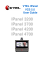
VTEL IPanel
VCS 5.0
User Guide
IPanel 3200
IPanel 3700
IPanel 4200
IPanel 4700
IPanel Systems
Videoconferencing
with
Data Sharing
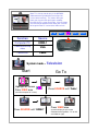
All-In-One Professional Solution
VTEL IPanel 3200/4200
26/32”
Internet
&
PC Applications
Internet/LAN
AC
“Easy to Drive”
One click operation
Multimedia
Presentations
Optional
Cable
HDTV
Initial Setup
IPanel 3700/4200
IPanel Systems
Videoco nferencing
with
Data Sh aring
All-In-One Professional Solution
VTEL IPanel 3200/4200
26/32”
Internet
&
PC Application s
Internet/LAN
AC
“Easy to Drive”
One click operation
Mult imed ia
Presentations
Optional
Cable
HDTV
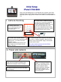
Please verify the following items are included with your shipment; camera with
mounting bracket, camera power supply, wireless keyboard, PC power supply,
DVD player power supply, panel IR remote, and software (including Windows XP
Pro).
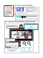
1. Camera mounting
B. Using a Philips screwdriver remove
the large silver screw from the bottom of
the camera and use it to mount the
camera mounting plate to the camera. Be
careful not to over tighten the screw.
Note: The L-shaped part of the mounting
plate (containing two small holes) should
face toward the back of the camera.
A. Remove camera and
camera mounting plate from the
camera box (located in the
accessories box).
+
C. Use two screws to mount camera
bracket and camera to the mounting plate
holding the PC. Be careful not to over
tighten the screws.
Align the camera bracket with the front
of the monitor and stick it down with the
double sided tape.
+
D. Connect the two cables (top of the LCD monitor) to
the camera --Yellow to composite, black to RS-232.
Make sure the camera power supply is connected to
camera and AC outlet.
All camera cables must be connected before
powering on the computer.
2. Power and network
B. Connect an RJ45 cable from your Internet or
LAN (local area network) connection to the
bottom of the computer in either RJ45 port.
C. Check all cable to ensure none came loose
during shipping.
A. Connect the power supply
adapter-- a transformer (“brick”)
with a large 4-prong plug on one
end to the computer’s power
receptacle located on the bottom
left side of the computer. The
power supply adapter is found in
the accessory box.
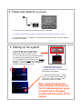
2. Power and network
(continued)
D. On the back of the panel ensure the power cable is connected
E. Configure your External IP network using the Network Configuration Guide in Section 6.
F. The hardware set up is complete. You should not have to do this again unless the system is
moved to a new location.
3. Starting up the system
A. Power on the system using the power
button on the top of the computer and the
power button on the front of the monitor
B. The system will start up like any other Windows
XP computer going through familiar screens.
C. This computer screen should be on the left side of
the monitor. If it isn’t go now to 3A “Arranging Proper
Displays” . Your monitor needs to be configured for
NORMAL Videoconferencing mode.
D. Double click on the red “V ball”
(“Start VTEL VCS” shortcut)
in the upper left corner. This launches the
videoconferencing software.
E. After a brief loading process, a large
VTEL “V ball” appears on the lower right
of the screen. This says that the videoconferencing software is loaded.
Note: if you do not see the
usual Windows XP screen on
the left side during start up go
to section 3A to configure
monitor and then return to this
section.
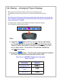
3A. Startup -- Arranging Proper Displays
When you turn on the flat panel and the PC you may find a display other than
The NORMAL videoconferencing mode of PC on the left and Videoconferencing on the
right.
The flat panel will start up in the same mode that it was when it was turned off.
So, if someone was watching TV and then turned off the system, the panel will
return (start up) in TV mode.
The following steps will get you to the NORMAL videoconferencing mode regardless
of the configuration of the panel during startup.
PC VC
VIEW
ASPECT
SOURCE
Steps:
A. Toggle the VIEW button until you see any side-by-side display…
i.e., the pick box on the screen will highlight just half of the screen.
It doesn’t matter what mode is actually on screen --even if all you
see is a blue screen. All you want is the pink box highlighting
just half of the screen.
B. Press the PC VC button. This will send a control signal to configure
the IPanel into videoconferencing mode (side by side).
Now you are in NORMAL Videoconferencing mode.
Return to step 3.
Function
Source
Computer PC
HDMI-1
Videoconferencing
video
VGA
Television
Cable
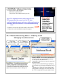
4. NORMAL Videoconferencing
A. The split screen at right will appear.
The left half is your local PC.
The right half is the videoconferencing section.
Place a Call
Audio Mute
Video Mute
Volume Control
Local Video
My IP Address
Exit VTEL Now
Cancel
Note: The keyboard mouse works normally as a
PC mouse when the cursor is in the PC area…
and the keyboard mouse works as a videoconferencing
controller when the cursor is in the videoconferencing
area.
B. Move the cursor to the right hand section (it will turn blue)
C. Right-click and the videoconferencing menu appears:
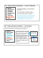
4A. Videoconferencing Menu – Placing a call
Managing the address book
1. Call Rate
2. IP Address
192 or 256 is a good
rate for the Internet
Enter the IP address
you are calling
Use tabs to toggle
between hand dialer
and address book
3. Click “Dial”
Address Book
Speed Dial Keys
Hand Dialer
Hand Dialer – for ad-hoc connections
• Use this 3-step process when you just want to
connect to another site not in the address book.
• Call yourself in loop back by dialing your own IP
address to test that your system is working OK.
Address Book– for routine connections
• From list -- Use your cursor to highlight in blue
the site and then “left double click”.
• Speed Dial – Place the cursor over the speed dial
key and “left click”
• Put any site on a Speed Dial key by highlighting
the horizontal entry and drag and dropping it onto a
key.
• To add a site -- Right click in the “address book”
(white) portion and bring up menu with “add” at the
top. This is how to add sites to your address book.
4B. Videoconferencing Menu
Place a Call
Audio Mute
Video Mute
Volume Control
Local Video
My IP Address
Exit VTEL Now
Cancel
An ICON appears on
your VC screen showing
status of audio and video mute
Muting -- On Master Menu click:
• Audio Mute so far site cannot hear you
• Video Mute so far site cannot see you
• Undo mute – click on the mute line on
Master Menu again or,
• Click on the ICON displayed on your VC
screen.
Volume: put your cursor where you
want the volume to go and left click.
Slide bar appears on PC side of screen
4C. Camera controls using the keyboard mouse
Using the mouse to control cameras is very natural … just
point where you want the camera to go.
Remote Camera
pan
Cursor is small and white when
moved into left (PC) zone
left/right/up/down
IPanel System s
V ideoconferencing
with
Data Sharing
All-In-One Professional Solution
VTEL IPanel 3200/4200
26/32”
Internet
&
PC A pplications
Internet/LAN
AC
“Easy to Drive”
One click operation
M ultim edia
Presentations
Optional
Cable
HDT V
Cursor is big and blue when
moved into right (VC) zone
Cursor is big and yellow when
moved into PIP window (PIP) zone
When in PIP zone the cursor controls
your local camera in the same way the
blue cursor controls the far camera
Left-click (and hold) to
move cameras
+
-
Zoom Zoom
In
Out
4D. Videoconferencing Menu – Local IP address
Hang Up
Address Book
Audio Mute
Video Mute
Volume Control
Send PC
Local Video
My IP Address
Cancel
Left-click on “My IP Address”. This is the number that
other people should call to reach this system. It’s like a
phone number.
The IP address appears on the top of the PC (left)
screen in PC/VC mode. If you are in VC mode (far site
video picture only) the IP address will not appear.
Note: VCS 5.0 only detects the user’s IP address when it
launches. If you change your IP while VCS 5.0 is running
it will not know about it and your calls won’t work. To
remedy this problem, just Exit VCS (by selecting Exit
VTEL Now), and then launch VCS 5.0 again.
4E. Videoconferencing Menu – Local Video
Local Video shows what your local camera is seeing. It normally goes into a PIP
(Picture In Picture) window in the videoconferencing section (right side).
Hang Up
Address Book
Audio Mute
Video Mute
Volume Control
Send PC
Local Video
My IP Address
Cancel
Shows your video in PIP window
Removes local video (PIP)
Show Local Video
Hide Local Video
Dock/Undock PIP
• Undock: makes local video into
PC-style window. You can
resize and move anywhere
move
• Dock: removes top blue bar and
“docks” PIP window where you
last put it
Your local
picture
(undocked)
size
4F. Videoconferencing Menu – Send PC
During a videoconference you can present PowerPoint slides (or any other PC application)
to the other participants.
For PowerPoint:
IP anel S ystems
Hang Up
Address Book
Audio Mute
Video Mute
Volume Control
Send PC
Local Video
My IP Address
Cancel
• While in PC/VC mode (like picture at right), start
your PowerPoint application in the left (PC) side.
Maximize the size of the slides locally.
V id eoconf erencing
wit h
Da ta S haring
A ll-I n-O ne P rof essional S olution
V TE L I Panel 3200/4200
26/32”
I nte rnet
&
P C A ppl icati ons
In te r ne t /L AN
AC
“E asy to Dri ve ”
On e cl ick o p era tio n
M ult im edi a
P rese ntat ion s
Op tion al
Cab le
HDT V
• Right-click on the video (right) side and bring up
the videoconferencing menu
• Select “Send PC” – an ICON appears on your
video side.
• In about 10-15 seconds the far site conferencing
unit will also see your PowerPoint slide … exactly
the same as you see it (same size and quality)
IP anel S ystems
V id eoconf erencing
wit h
Da ta S haring
A ll-I n-O ne P rof essional S olution
V TE L I Panel 3200/4200
26/32”
• Click on your PowerPoint slide and it will
automatically (like normal) advance to the next
slide. In about 5-10 seconds the remote site will
see the new slide.
I nte rnet
&
P C A ppl icati ons
In te r ne t /L AN
AC
“E asy to Dri ve ”
On e cl ick o p era tio n
M ult im edi a
P rese ntat ion s
Op tion al
Cab le
HDT V
• When finished sharing slides select “Stop
Sending PC” from the main white menu.
Note: The time it takes to transfer a slide is
dependent upon the bandwidth of the connection
between IPanel systems.
Note: If you are sending PC slides to the far site
and they start “Send PC” at their end, it will cancel
your Send PC and you will start receiving their PC
data.
Tip: Bring your flash drives to the meeting (videoconference or
local). Load your PC files into the IPanel. There is a convenient
USB port on the upper right-hand side of the IPanel computer.
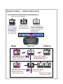
System modes -- videoconferencing
The IPanel has three main videoconferencing modes of operation.
You can toggle from one mode to another using the keyboard function
keys on the wireless keyboard
I P a n e l S y s te m s
IPanel Systems
V i d e o c o n fe r e n c i n g
w i th
D a ta S h a ri n g
A l l- I n - O n e P r o f e s s i o n a l S o l u ti o n
V T E L IP a n e l 3 2 0 0 /4 2 0 0
Vide oco nf er enc ing
wit h
Da ta Sha rin g
A ll-In-One P rofes sional S olution
V TEL IPanel 3200/4200
26/32”
26 /32 ”
In te rn et
&
PC Ap plica tio ns
In te rn e t
&
P C A p p l i c a t io n s
Inte rnet/L AN
AC
“Easy t o D riv e”
One cl ick operati on
M ult ime dia
Pr es en tat ion s
In te r n e t/L AN
Optional
Cable
AC
M u l ti m e d i a
P r e s e n ta t i o n s
HDTV
“ E a s y to D r iv e ”
O n e c lic k o p e r a tio n
O p t io n a l
C a b le
HD T V
PC and VideoConferencing side
by side - NORMAL
Normal operation
for videoconferencePC information on
left, video on right
PC VC
VIEW
ASPECT
SOURCE
Go To
Start
Return
I P a n e l S y s te m s
IPanel Systems
IPanel Systems
Vide oco nf er enc ing
wit h
Da ta Sha rin g
A ll-In-One P rofes sional S olution
V TEL IPanel 3200/4200
Full Screen PC
See full screen of received
PC data in videoconference.
or see full size presentation
locally when not in a
videoconference
Videoconferencing
See full screen of far
site in videoconference
V i d e o c o n fe r e n c i n g
w i th
D a ta S h a ri n g
A l l- I n - O n e P r o f e s s i o n a l S o l u ti o n
V T E L IP a n e l 3 2 0 0 /4 2 0 0
26/32”
26 /32 ”
In te rn et
&
PC Ap plica tio ns
In te rn et
&
PC Ap plica tio ns
In te rn e t
&
P C A p p l i c a t io n s
Mult ime dia
Pr es en tat ion s
Optional
Cable
Vide oco nf er enc ing
wit h
Da ta Sha rin g
A ll-In-One P rofes sional S olution
V TEL IPanel 3200/4200
26/32”
Inte rnet/L AN
AC
“Easy t o D riv e”
One cl ick operati on
Inte rnet/L AN
AC
M ult ime dia
Pr es en tat ion s
In te r n e t/L AN
AC
“ E a s y to D r iv e ”
O n e c lic k o p e r a tio n
“Easy t o D riv e”
One cl ick operati on
M u l ti m e d i a
P r e s e n ta t i o n s
HDTV
Optional
Cable
HDTV
O p t io n a l
C a b le
HD T V
Highlight left screen
Press VIEW once
(to make computer full screen)
Press VIEW twice
(to return display to split screen
videoconferencing mode)
IPanel Systems
IPanel Systems
IPanel Systems
Vide oco nf er enc ing
wit h
Da ta Sha rin g
A ll-In-One P rofes sional S olution
V TEL IPanel 3200/4200
26/32”
In te rn et
&
PC Ap plica tio ns
In te rn et
&
PC Ap plica tio ns
Inte rnet/L AN
AC
“Easy to D rive”
One clic k operat ion
Vide oco nf er enc ing
wit h
Da ta Sha rin g
26/32”
Int er ne t
&
PC App licat ion s
Mult ime dia
Pr es en tat ion s
Internet /LAN
AC
HDTV
A ll-In-One P rofes sional S olution
V TEL IPanel 3200/4200
26/32”
Mult ime dia
Pr es en tat ion s
Optional
Cable
Vid eo con fe ren cing
with
Da ta Sh ar ing
A ll-In-O ne Profes sional Solution
VTE L IPanel 3200/4200
Inte rnet/L AN
AC
“Easy t o D riv e”
One cl ick operati on
M ultim ed ia
Pr ese nta tion s
O ptio nal
C able
“Easy t o D riv e”
One cl ick operati on
Optional
Cable
HDTV
HD TV
Highlight right screen
Press VIEW once
(to make video full screen)
Press VIEW twice
(to get to split screen)
Press PC VC once
(to get video on right)
Note: This side-by-side display is the NORMAL
Videoconferencing mode because it aligns the
cursor control correctly. This means when you
move your cursor to the right it goes smoothly
from the left (PC) screen to the right. If these images
are reversed you would have to move your cursor to
left to go from the PC screen to the Video screen.
IPanel Systems
Videoconferencing
with
Data Sharing
All-In-One Professional Solution
VTEL IPanel 3200/4200
26/32”
Internet
&
PC Applications
Internet/LAN
AC
Multimedia
Presentations
“Easy to Drive”
One click operation
Op ti onal
Cab le
HDTV
PC VC
Function
Source
Computer PC
HDMI-1
Videoconferencing
video
VGA
Television
Cable
VIEW
ASPECT
System mode -- Television
Start
Go To
I P a n e l S y s te m s
IPanel Systems
Vide oco nf er enc ing
wit h
Da ta Sha rin g
A ll-In-One P rofes sional S olution
V TEL IPanel 3200/4200
V i d e o c o n fe r e n c i n g
w i th
D a ta S h a ri n g
A l l- I n - O n e P r o f e s s i o n a l S o l u ti o n
V T E L IP a n e l 3 2 0 0 /4 2 0 0
26/32”
26 /32 ”
In te rn et
&
PC Ap plica tio ns
In te rn e t
&
P C A p p l i c a t io n s
Inte rnet/L AN
AC
“Easy t o D riv e”
One cl ick operati on
M ult ime dia
Pr es en tat ion s
In te r n e t/L AN
Optional
Cable
AC
M u l ti m e d i a
P r e s e n ta t i o n s
HDTV
“ E a s y to D r iv e ”
O n e c lic k o p e r a tio n
O p t io n a l
C a b le
HD T V
Highlight left screen
Press VIEW once
Press SOURCE until “Cable”
(to make computer full screen)
I P a n e l S y s te m s
IPanel Systems
V i d e o c o n fe r e n c i n g
w i th
D a ta S h a ri n g
A l l- I n - O n e P r o f e s s i o n a l S o l u ti o n
V T E L IP a n e l 3 2 0 0 /4 2 0 0
Vide oco nf er enc ing
wit h
Da ta Sha rin g
A ll-In-One P rofes sional S olution
V TEL IPanel 3200/4200
26 /32 ”
26/32”
In te rn e t
&
P C A p p l i c a t io n s
In te rn et
&
PC Ap plica tio ns
Inte rnet/L AN
In te r n e t/L AN
AC
“ E a s y to D r iv e ”
O n e c lic k o p e r a tio n
AC
M u l ti m e d i a
P r e s e n ta t i o n s
O p t io n a l
C a b le
“Easy t o D riv e”
One cl ick operati on
M ult ime dia
Pr es en tat ion s
Optional
Cable
HDTV
HD T V
Press SOURCE until “HDMI-1”
Press VIEW twice
(to return display to split screen
videoconferencing mode -- PC on left
and video on right)
SOURCE
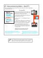
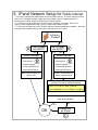
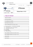
6. IPanel Network Setup for Public Internet
• The IPanel is designed to videoconference over the public Internet. The initial setup may involve
your local IT (computer network) support person to configure your IP network parameters-especially your network firewall and some internal IPanel settings.
• This will only have to be done once at initial system installation. Thereafter, the user will
simply call other videoconferencing systems using the IPanel address book.
• This decision tree flow chart covers all of the common network configuration conditions. Go to the
next page for the detailed step-by-step actions required (items A, B, and C)
Is there a
Firewall?
NO
A
YES
Does network
use DHCP?
NO
YES
Does network
use DHCP?
YES
IPanel Settings
NO
IPanel Settings
• IP Address
• Subnet Mask
A
• IP Address
B
B
• Subnet Mask
• Default Gateway
• Default Gateway
• Preferred DNS Server
• Preferred DNS Server
• Alternate DNS Server
• Alternate DNS Server
Modem internal addresses
Source: ISP
Firewall internal addresses
Source: Network admin
Configure Firewall for Videoconferencing
• Open 1718-1720 TCP ports (incoming)
• Open 5004-6004 TCP and UDP ports (outgoing)
• Forward traffic to IPanel
Does firewall do NAT?
NO
YES
OK
Enable NAT
on IPanel
C
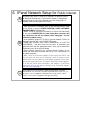
6. IPanel Network Setup for Public Internet
A
B
C
By default, your IPanel is setup to use automatic IP detection (DHCP)
on both of its Ethernet ports. If your internal network is configured to
use DHCP (which is the most common case) then simply plug in a
network cable into either port on the IPanel.
• Once you have this information, open up the network properties page
on the IPanel by going to START->CONTROL PANEL->NETWORK
CONNECTIONS on Windows XP
• RIGHT CLICK on "Local Area Connection" or "Local Area Connection
2" and select PROPERTIES (see note below) One connection will
say connected, one will say network cable unplugged. Use the
connected network choice.
• In the properties page LEFT CLICK on "Internet Protocol (TCP/IP)" to
highlight it and then press the PROPERTIES button.
• Toggle both selections from "Obtain...Automatically" to "USE THE
FOLLOWING…” and then enter the five pieces of information you
gathered earlier into the appropriate boxes. Once you've entered this
information press OK to close the dialog.
• Verify network connectivity by selecting Internet Explorer on the
IPanel and connecting to a public web site (it is the same process as
any other computer).
• Note: there are 2 Ethernet adapters on the back of the IPanel. You
can use either one, but if you are setting up a static IP address on your
IPanel make sure you setup the same network properties for the same
port you plug your cable into. (Facing the back of the iPanel adapter 1
is on the left ("Local Area Connection") and adapter 2 ("Local Area
Connection 2") is on the right. It's perfectly ok to set-up both adapters
with the same information.)
Load VTEL's System Configuration. Under the Network tab, check the
"Enable NAT" box and enter your public/external IP address in the box (you
may have to ask your ISP/Network Administrator for this address). Press
"OK" to close System Configuration and apply the settings.
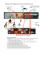
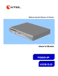
Attaching VTEL Backpack (PC) to Olevia 537H/542i Flat Panel
Mechanical Assembly
A. Mount the camera to the LCD monitor using the camera mounting bracket.
B. Place the camera umbilical cable (cables 3,4,5) behind the PC mounting
bracket and mount the PC assembly to the LCD monitor using four screws
Cable Assembly
1)
2)
3)
4)
Attach DVI/HDMI cable and securely plug it into HDMI -1 on monitor
Attach Video dongle
Attach both ends of the camera power supply
Attach VISCA cable to port labeled RS-232 (camera) and other
end into right COM port (COM 2) (part of umbilical)
5) Attach s-video cable to camera s-video port and the other end into connector
on video dongle with arrow pointing towards PC
6) Plug the RF Receiver of the keyboard into one of the USB ports
7) The keyboard and the dongle receiver are synchronized at the factory.
If you need to resynchronize the keyboard, use the following process.
7A) Setting ID: press ID button on dongle receiver, the green
LED will flash which means the ID is searching
7B) Press the ID button on the keyboard. The green LED on the
dongle receiver will turn off. This means the
connection between the keyboard and the
dongle receiver is successful.
5. Camera
S-video
4. Camera
RS 232 control
3. Camera
power
6. Dongle receiver
into USB port
7A. Push ID button -the green LED will flash
7B. Push ID button -the keyboard will
connect to dongle receiver
2. Video
dongle
XX
1. HDMI
HDMI -1
Port
Attaching VTEL Backpack (PC) to Olevia 537H/542i Flat Panel
13. IP/LAN network
15. VGA to external projector
(requires optional VGA splitter
Cable)
14. Power
adapter
7. LCD
Control
10. Y-Splitter
12. Cable TV
8. Audio
9. Audio
11. Microphone
Cable Assembly Continued
7) Screw in each end of the LCD panel control cable. Be sure to use the lower COM port (COM 1)
on the PC
8) Plug one end of this audio cable into the Y-splitter. Match the red and white jacks
to their audio receptacles on LCD panel
9) Plug one end of this audio cable into the into the Y-splitter. Match the red and white jacks
to their right-most audio receptacles on LCD
10) Plug the Y-splitter into the green mic jack on the PC.
11) Plug in microphone into pink jack on the PC
12) If available, plug in your coaxial cable TV feed for TV viewing
13) Attach your RJ-45 IP/LAN network cable to either port on PC
14) Attach the power cable here and plug the AC side into a surge protector
15) Using an optional VGA splitter cable attach a VGA projector to the PC