1
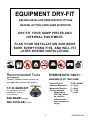
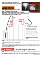
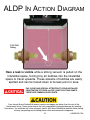
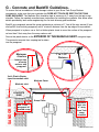
INSTALLATION INSTRUCTIONS
FOR B409 DOUBLEWALL TANK SUMP
WITH REINFORCED BOTTOM
Use this manual
for the B-830-D-AB
series transition
containment sumps
ii-B409-DW-12A
WWW.SBRAVO.COM
800-AT-BRAVO
The B-409 Doublewall Sump w/Bottom from S. Bravo Systems, Inc. MUST be installed
by Bravo Certified Contractors. Details can be found at w w w. s b r a v o . c o m / c e r t
READ THESE INSTRUCTIONS - KEEP FOR FUTURE REFERENCE
TABLE OF CONTENTS
DRY FITTING SUMP & EQUIPMENT................................p. 4
A) Installing & Securing..........................................................p. 5
Install & Test Penetration Fittings...................................... p. 5 (A.4)
B) Mantadory Air Integrity Test............................................... p. 6
C) Vacuum / Hydrostatic Filling.............................................. p. 7-8
D) Advanced Leak Detection Procedure................................p. 9-10
E) Connecting to Manometer................................................. p. 11
F) Concrete & Backfill Guidelines......................................... p. 12
Filling Bravo Systems Double Wall Products with
Brine (saline) solution will void the product warranty.
You must use only Bravo-Supplied Interstitial Fluid.
- Closely adhere to all directions and warnings indicated on the product
or contained in these instructions. This includes following the OTHER manufacturers
recommendations and Installation guidelines including -but not limited to- equipment
associated or in contact with, Bravo Systems Products.
- Warranty is void if there is any evidence of modification, abuse,
negligence or improper installation.
SAFETY FIRST! S. Bravo Systems, Inc. urges you to carefully adhere to the normal safety
procedures and precautions followed by your company. Please follow the mandates and
compliances decreed by OSHA, local, State and federal regulations regarding the use of this product.
WARRANTY
All containment systems sold by S. Bravo Systems, Inc. are warranted to be free from defects in material and workmanship for a period of one year from date of
purchase. This warranty will be limited to the repair and replacement of Bravo parts only and will exclude all claims for labor or consequential damage. No other
express warranties given and no affirmation of S. Bravo Systems, Inc., or its agents and/or representatives, by words or action, will constitute a warranty. IT IS
EXPRESSLY AGREED THAT THIS WARRANTY WILL BE IN LIEU OF ALL WARRANTIES OF FITNESS AND IN LIEU OF THE WARRANTY OF MERCHANTABILITY.
This warranty is void if there is any evidence of modification, abuse, negligence, or improper installation. If any fittings or components, other than S. Bravo Systems
approved fittings or components, are used in conjunction with any S. Bravo Systems product, the warranty pertaining to these products is immediately void.
2
ii-B409-DW-12A
IN CALIFORNIA: You must observe and satisfy the volume containment requirements found in
the California Code of Regulations CCR Title 23, Article 3, section 2631(d)(1).
The regulation can be found at
http://www.swrcb.ca.gov/water_issues/programs/ust/regulatory/
under California Regulations > UST Regulations
BEFORE PENETRATING FIBERGLASS
WALLS ENSURE THAT EACH DOUBLE WALL
FIBERGLASS SUMP IS HOLDING VACUUM
It is REQUIRED to visually check the Vacuum gauge on each
and every Bravo Systems Double Wall product and write on its
FAX report Vacuum level, name of observer, and date for
every DoubleWall Sump.
WARRANTY IS VOID:
IF ANY OF THE FOLLOWING OCCUR
A) There is a failure to comply with the Required written report guidelines as stated above.
B) Double Wall Products are DOUBLE-STACKED, stored or shipped in a negligent way.
C) Any packaging or wrapping materials are removed before the item reaches It’s destination.
D) Double Wall Sump Products, Failure to call Bravo Systems If Vacuum level on product is
less than 12” HG (Vacuum) (323) 888-4133, refer to sump for further details.
E) Double Wall Sump Products are tested per the SB989 Testing procedures. The interior
of these sumps must NOT be filled with liquid to any level.
F) Double Wall Sumps are filled with an unapproved interstitial fluid, or if adhesives or
sealants are used that are not Bravo-approved.
If there is any indication or suspect damage, you must mark the freight paperwork
“Suspect Freight Damage” as directed by your Contractor Warranty sheet.
3
ii-B409-DW-12A
EQUIPMENT DRY-FIT
- BEFORE INSTALLING PENETRATION FITTINGS
- BEFORE CUTTING OPEN SUMP INTERSTICE
DRY-FIT YOUR SUMP PIECES AND
INTERNAL EQUIPMENT.
PLAN YOUR INSTALLATION AND MAKE
SURE EVERYTHING FITS, AND WILL FIT
LATER DURING INSTALLATION.
Recommended Tools
HYDROSTATIC ONLY!!
(NOT PROVIDED)
MANOMETER KIT (PER SUMP)
Power/air Sanders. Acetone to clean up
tools/applicators. Power Cutting Tools.
-
T-F-33-SAND-KIT
5/8” sanding disc backs and
centralizers for all Bravo
Systems Fittings
SVA-BARB per sump
VAC-KIT-D-AB per site
4
Interstitial fluid
Standard Manometer
Manometer Bracket
Factory-Installed
Nylon tubing
w/20”Hg Vacuum
on interstice
w/Combination
Pressure/Vacuum
Gauge
TOTAL HEIGHT
4’ = 5 gal
5’ = 6 gal
6’ = 7 gal
7’ = 8 gal
ii-B409-DW-12A
A - INSTALLING AND SECURING YOUR B409
BEFORE INSTALLING PENETRATION FITTINGS
ENSURE THAT THE SUMP BODY IS HOLDING VACUUM.
If the gauge is Below 12 inches of mercury (Hg/Vacuum), then pressurize the
sump interstice to 4 PSI and submerge the gauge and tubing assemblies.
Soap test the test tubing fittings on the walls. If an air leak is found, contact
the factory. If no leak at the tubing is found, soap test the rest of the sump
surface starting with the exterior. Visually inspect for damage. If the leak is found,
patch per repair directions in this manual.
If the gauge is AT OR ABOVE 12 INCHES OF MERCURY, proceed to Step A.1
A.1 - Visually inspect the parts provided by Bravo Systems for In-transit damage and/or missing
parts. Continue to keep the Sump clean of debris throughout your installation process.
A.2 - Set your B409 Piping Sump where it must be per site plans. Secure the Sump to avoid
movement while penetrating.
A.3 -
Mark where you will penetrate the Base/Tank Collar wall.
A.4 - Install Penetration Fittings per their respective Installation Instructions. You must NOT
disturb the penetration fittings while the sealant/adhesive is drying. Allow for the maximum cure time
as recommended by the manufacturer of the fittings before pressurizing & soaping to test for leaks.
DO NOT FILL DOUBLE WALL PENETRATION FITTINGS
WITH FOREIGN MATERIALS, SEALANTS or ADHESIVES.
While Fiberglassing, curing, or sitting overnight, keep the
SVA-BARB in place. This will relieve pressure on the Interstice
while the sumps are heating up or cooling off.
SAVE THESE PIECES, DO NOT LOSE THEM! Remove the SVA-BARB when ready to test.
Gauge
Assembly
CAP
5
SVA-BARB
ii-B409-DW-12A
B - MANDATORY AIR
INTEGRITY TEST
B.1 - Use test assembly and pressure sump to no more
than 4 PSI. Close off with ball valve and resume other work.
Allow 1 Hour before recording pressure.
BRAVO
QUALITY
STANDARD
FIELD AIR INTEGRITY INSPECTION TEST : Hold pressure for a
minimum of 1 hour for a Field Integrity Inspection Test. The Tank Sump PASSES
the integrity test if the Sump shows NO signs of continuous pressure decay.
IF TEST PASSES - CONTINUE ON TO THE HYDROSTATIC FILL & INTEGRITY TEST.
B.2 - IF ANY LEAKS ARE FOUND!!
Look at edges and corners for pinhole leaks. For large leaks, consult factory.
A: Locate leak point(s) and mark with marker so you can locate it / monitor it.
B: Repair or reinstall doublewall penetration fittings according to your doublewall penetration
fitting manufacturers’ Installation / Maintenance Instructions.
C: Abrade a 2” diameter area centered on the leak point until natural resin/fiberglass material
can be seen. Dust with shop brush or compressed air and do not use shop towels or
acetone on the abraded area(s). Then apply a 3-layer strip of 2” x 2” resin-saturated
fiberglass mat squarely on the abraded area.
D: Roll out any air bubbles with chamfer roller. Let cure.
E: After cure, knock down fiberglass hairs, and apply another flow coat of
resin only. Apply any extra resin to repaired leak point(s) while still wet.
Let cure for a minimum of 4 hours @ or above 75° F.
FOR HYDROSTATIC MONITORING - PROCEED TO SECTION C.
FOR CONTINUOUS VACUUM MONITORING - The B409 DoubleWall
Solid Sump w/Bottom cannot exceed 16” of Mercury. (Vacuum)
Follow your vacuum system manufacturer’s installation instructions
to install, seal, and monitor the doublewall system with vacuum.
Connect the SVA-BARB to
your factory-installed gauge
for vacuum monitoring
Continue to Section F.
Ensure that the fittings that are being used with the
Vacuum Monitored System can withstand the amount
of Vacuum your Monitoring System will generate.
6
ii-B409-DW-12A
C - VACUUM / HYDROSTATIC FILLING
FIELD AIR INTEGRITY INSPECTION TEST :
YOUR PRODUCT WARRANTY WILL BE VOID IF YOU DO NOT Hold pressure
for a minimum of 1 hour for a Field Integrity Inspection Test. After passing
the pressure test, it is HIGHLY RECOMMENDED that the 4 PSI is
maintained for as long as possible, up until the time of backfill.
YOUR PRODUCT WARRANTY WILL BE REVOKED IF YOU
CHOOSE TO SKIP THE AIR INTEGRITY TEST OUTLINED IN YOUR
COPY OF YOUR PRODUCT INSTALLATION INSTRUCTIONS. YOU MUST COMPLETE THE
PRESSURE TEST PRIOR TO HYDROSTATIC FILLING OF THE SUMPS.
The Bravo Double Wall product’s ship from the factory with a combination gauge factory- installed
and held under 20” of mercury / vacuum.
C.1 - After passing the Field Air Integrity Test per the Installation Instructions and there are no
signs of leaks, you must cut the permanently affixed pipe plug from the tubing connected to the side
wall. This is NOT the tubing with the gauge connected to it.
C.2 -
Connect (newly cut) open end of tubing to barb-and-ball-valve assembly. (sold seperately)
A 36” length of clear tubing is factory installed to the barb-and-ball-valve assembly.
Barb & Ball Valve
Assembly
Cut Plug end off
from tubing
Connect
Assembly to
tubing
After the penetration
fittings have been
installed, the vacuum has
been lost. Pressure/soap
tests should have been
conducted prior to filling
the sumps with liquid.
You must cut off the barbed
plug and connect the
provided Barb & Ball Valve
Assembly. Close off the ball
valve and prepare the
Venturi Vacuum Generator
and air supply to be used to
fill Sump with liquid.
7
ii-B409-DW-12A
C.3 -
Close off ball valve completely and
prime the open ended 36” length of clear tubing
with provided Interstitial Fluid. Use a liquid funnel.
Filling Bravo Systems Double
Wall Products with Brine
(saline) solution will void the product
warranty. You must use only Bravo-Supplied
Interstitial Fluid, part # IMF-1GAL
Barb &
Ball Valve
Assembly
Venturi Vacuum Generator
After liquid fill, Conduct the
Advanced Leak Detection
Procedure, then Cut the ball
valve assembly from its tubing
and connect open end of tubing
to Primary manometer. Also
unthread the Gauge Assembly
and use provided PVC threaded
plug to close off open test port
fitting.
Bucket
C.4 - After filling the tubing all the way to the ball valve, insert open end into your liquid source.
(5 gallon bucket filled with fluid is recommended.)
C.5 - When ready, pull vacuum using the Venturi Vacuum Assembly (sold seperately) to 20 Inches
of mercury. Then SLOWLY open ball valve and allow Interstitial fluid to flow freely into the system at a
rate of about 2 gallons a minute.
...SLOWLY open ball valve...
C.6 - STOP PULLING VACUUM WHEN THE LIQUID IS 2-3 INCHES FROM THE VERY TOP OF
THE INTERSTITIAL SPACE / TEST PORT. This is easily visible while filling the DoubleWall Product.
8
ii-B409-DW-12A
D) ADVANCED LEAK DETECTION
PROCEDURE
A Bravo Systems Exclusive detection method
D.1 - Clear debris from the top open area of the DoubleWall Product and ensure that the
interior walls are clean of debris and visible.
D.2 - Apply Vacuum to the sealed interstitial space with the Venturi Vacuum Assembly, and
generate 20”-30” of vacuum for a MINIMUM of Five [ 5 ] Minutes.
CHECK WITH YOUR EQUIPMENT MANUFACTURERS
INSTALLATION MANUALS FOR INSTALLATION
GUIDELINES AND/OR EQUIPMENT LIMITS REGARDING
VACUUM AND PRESSURE LEVELS.
D.3 - As stated in your Instructions, the liquid level is deliberately not filled to the very top
of the interstitial space. This pocket of air is necessary to visually check the topmost level of
liquid all the way around the Sump for indication of a leak.
D.4 - Visually inspect the interior walls for signs of trailing (very small) bubbles floating to
the top of the liquid level within the interstitial space.
These air bubbles are visible within the vertical and horizontal
channels of the walls. For Tank Sumps look below the reducer.
On the top hat reducer of a Tank Sump, any bubbles will burp
consistently.
PAY CLOSE AND SPECIAL ATTENTION TO FIELD-INSTALLED
PENETRATION FITTINGS and FRP JOINTS ON TANK SUMPS.
THESE ARE COMMON LEAK POINTS.
Even though Bravo DoubleWall product corners and edges are thicker than the rest of the
Containment sump, These areas recieve the most supceptable to physical damage by Installing
Contractors. You would do well to be extremely careful with these DoubleWall products while storing,
moving, transporting and Installing these critical environmental components.
9
ii-B409-DW-12A
ALDP IN ACTION DIAGRAM
F-32-TS-D
Fitting
Here a leak is visible while a strong vacuum is pulled on the
Interstitial space, forcing tiny air bubbles into the interstitial
space to travel upwards. These streams of bubbles are easily
spotted and can be traced down to its leak point or area.
PAY CLOSE AND SPECIAL ATTENTION TO FIELD-INSTALLED
PENETRATION FITTINGS and FRP JOINTS ON TANK SUMPS.
THESE ARE COMMON LEAK POINTS.
Even though Bravo DoubleWall product corners and edges are thicker than the rest of the
Containment sump, These areas recieve the most supceptable to physical damage by Installing
Contractors. You would do well to be extremely careful with these DoubleWall products while storing,
moving, transporting and Installing these critical environmental components.
10
ii-B409-DW-12A
E - CONNECTING TO MANOMETER
E.1 - At this point, after the ALDP test, the interstice should still be holding vacuum. Maintain 20”
of Vacuum and slowly open ball valve to let fluid into the interstice until it exits the venturi assembly.
Visually check whether the fluid level reaches the top of the interstitial space.
E.2 - Cut the barb & ball valve assembly free by cutting the tubing just below it and connect open
end of tubing to the bottom of the primary Manometer.
E.3 - Remove the Barb, Tubing & Combination gauge assembly from the test port fitting on the
side of the sump. Install a threaded pipe plug into the open test port fitting and adjust Primary
manometer bracket so the manometer is in a position clear of the sump cover.
Remove Entire Gauge
Assembly by backing
off threaded barb fitting.
Cut off barb
& ball valve
assembly.
Fig. E.7
Sensor Cable
Cap assembly
Install PVC Plug
Connect Tubing to
Primary Manometer
Continuous Monitoring
Interstitial & Leak
Detection of Secondary
Containment
P-Traps OK since vacuum fill
method leaves no room for air.
E.4 - It is not uncommon for some interstitial fluid to be lost while connecting the tubing to the primary
manometer. This is ok. Replace lost fluid by topping off manometer with interstitial fluid until the liquid level
reaches just 2 inches below the top of manometer.
E.5 - Hydrostatic Field Integrity Test - Mark the date and time of test and
manometer level. Allow 1 hour to look for a change in level. No change in level or visible leaking means
box passes test.
E.6 -
If interstitial test fluid changes its level more than 1/4”, visually look for any signs of leaking around
fittings both interior and exterior to sump. Pay special attention to field installed fittings.
E.7 -
If interstitial monitoring is required, install a California Listed Hydrostatic Sensor (LG-113) using the
sensor manufacturer’s fitting. Run sensor cable through the cap assembly (see Fig. E.7). Level sensor
should be set to bottom of manometer. Follow your leak detector manufacturer’s installation instructions.
Cover the manometer with cap and fasten with wire and lead crimp seal.
11
ii-B409-DW-12A
G - Concrete and Backfill Guidelines.
To ensure that no immediate or future damage is done to your Bravo Tank Sump Reducer
components, make sure that your manhole skirt DOES NOT TOUCH OR REST ON THE TANK
SUMP SHOULDER. The Manhole Skirt should be kept at minimum of 4” away from the tank sump
shoulder. Follow the manhole manufacturers instructions for installing the manhole. Also follow other
details provided by tank and/or engineering firm for tank driveway pad installation.
Backfill your peagravel around the sump maintaining a minimum of 1’ foot all the way around (if your
site backfill is not entirely peagravel) and 4” minimum distance from the top edge of sump reducer.
When peagravel is in place, use a 3mil or thicker plastic sheet to cover the surface of the peagravel
no less than 2 feet away from the sump reducer wall.
Secure this plastic barrier to the EXTERIOR OF
This prevents concrete from seeping too far down
into the peagravel.
THE MANHOLE SKIRT using duct tape.
Minimum
4 inches
1” to 1-1/2”
Distance
between top
of sump
reducer and
peagravel
3mil+ Plastic Barrier
taped to manhole skirt
Manhole Cover
Manhole skirt
SAND OR SOIL
CONCRETE
SLAB
Sump Cover
Manhole
skirt min.
4” away
from Tank
sump
shoulder
Min 1’ foot
peagravel all
around sump
12
ii-B409-DW-12A