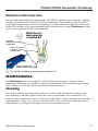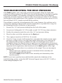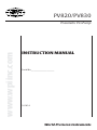
1
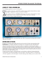
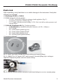
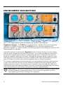
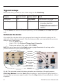
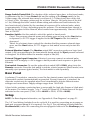
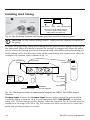
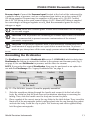
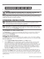
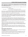
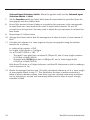
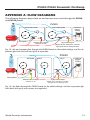
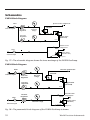
PV820/PV830 www.wpiinc.com Pneumatic PicoPump INSTRUCTION MANUAL Serial No._____________________ 101614 World Precision Instruments Other WPI Favorites M3301 Manual Micromanipulator The world’s most widely used micromanipulator Weighing just 550 grams and employing a slim space-saving design, this well-built micromanipulator outsells all others worldwide for high precision experiments where magnification is in the range of up to 250. Its design allows units to stand tightly grouped — since all control knobs project to the rear. And because control knobs are clustered within an 8 cm area in a single vertical plane, resolution is quick — the hand works blindly while the eye monitors the microscopic image. Vernier scales allow readings to 0.1 mm; x-axis fine control allows readings to 10 microns. The instrument employs rack-and-pinion drive, V-shaped guideways, and cross roller bearings, so all movement is sure and M3301R repeatable, without drift, sideplay, backM3301L lash, or sticking. Contact parts are milled of M3301-M3-R hardened steel for high performance and long life. Left- or right-handed versions of the M3301 M3301-M3-L are supplied with a standard 12 mm 502105 clamp (M2) and one microelectrode holder (M3301EH). 15873 Electrode Holder not included Shown on optional M-3 Tilting Base with optional 5-lb Weight #5464 Manual Manipulator, right-handed Manual Manipulator, left-handed Manual Manipulator (right handed) & Tilting Base Manual Manipulator (left handed) & Tilting Base Axis Adjustment Tool PZMIII Precision Stereo Microscope WPI’s third-generation stereomicroscope, PZMIII, is an ideal tool for tissue dissection, cell injection, specimen manipulation, electrode inspection, and many other applications that require a magnified, stereo viewing and ample working distance. It offers the leading brand’s quality and performance at an affordable price. Advanced optics provide the sharpest image that can only be found among the best of this class. It is superior to many stereomicroscopes costing almost twice as much. Zooming is achieved by a spring-loaded knob that is smooth and effortless. The compact size and light weight make it more stable and easily manipulated on the boom stand. A specially designed photo/ video module is used in the trinocular version of the microscope (PZMTIII) for photo, video, or digital imaging. In addition, an extensive list of optional accessories is available that can make the PZMIII suitable for almost any bio-research applications requiring a stereomicroscope. There are LOTS of options. PV820/PV830 Pneumatic PicoPump CONTENTS ABOUT THIS MANUAL ........................................................................................................................ 1 INTRODUCTION.................................................................................................................................... 1 PV820 ............................................................................................................................................... 2 PV830 ................................................................................................................................................ 2 Notes and Warnings....................................................................................................................... 2 Parts List ............................................................................................................................................ 3 Unpacking......................................................................................................................................... 5 INSTRUMENT DESCRIPTION ............................................................................................................ 6 Typical Setups .................................................................................................................................. 8 Solenoid Controls............................................................................................................................ 8 Rear Panel ......................................................................................................................................... 9 Setup .................................................................................................................................................. 9 OPERATING INSTRUCTIONS ...........................................................................................................12 Techniques In Microinjection .....................................................................................................12 MAINTENANCE ...................................................................................................................................17 Cleaning ..........................................................................................................................................17 ACCESSORIES......................................................................................................................................18 Replacement Parts ........................................................................................................................18 Legacy Replacement Parts ..........................................................................................................18 TROUBLESHOOTING THE HOLD PRESSURE ..............................................................................19 SPECIFICATIONS .................................................................................................................................20 APPENDIX A: FLOW DIAGRAMS ....................................................................................................21 Schematics......................................................................................................................................22 APPENDIX B: DROPLET VOLUME ..................................................................................................23 Volume of a Micropipette ...........................................................................................................23 BIBLIOGRAPHY ...................................................................................................................................24 INDEX ....................................................................................................................................................25 DECLARATION OF CONFORMITY ..................................................................................................26 WARRANTY ..........................................................................................................................................27 Claims and Returns ......................................................................................................................27 Repairs .............................................................................................................................................27 Copyright © 2014 by World Precision Instruments, Inc. All rights reserved. No part of this publication may be reproduced or translated into any language, in any form, without prior written permission of World Precision Instruments, Inc. World Precision Instruments iii iv World Precision Instruments PV820/PV830 Pneumatic PicoPump ABOUT THIS MANUAL The following symbols are used in this guide: This symbol indicates a CAUTION. Cautions warn against actions that can cause damage to equipment. Please read these carefully. This symbol indicates a WARNING. Warnings alert you to actions that can cause personal injury or pose a physical threat. Please read these carefully. NOTES and TIPS contain helpful information. Fig. 1—PV820 Pneumatic PicoPump (top) and PV830 Pneumatic PicoPump with vacuum regulation (bottom) INTRODUCTION Designed to simplify intracellular injection and a variety of other microinjection tasks, PicoPumps use carefully regulated air pressures for securing cells and injecting them with fluid. Injected volumes range from picoliters to nanoliters. Separate ports supply positive and negative pressure—positive pressure for high-pressure ejection, and suction for supporting the cell or for filling the pipette from the tip. A second pressure port maintains a low positive “holding” pressure to the injecting pipette between injection pulses, to prevent fluid uptake through capillary action. Timing, ejection pressure, holding pressure, and suction are adjusted independently by control knobs and indicator gauges on the front panel. Injection pressure is controlled by a 20-turn regulator on the front panel. A built-in timing circuit allows precise control of the World Precision Instruments 1 amount of time that the injection pressure is applied to the output port. Time intervals can range from 10 seconds down to 10ms or less, depending on the eject pressure setting. The injection pressure interval can be triggered manually on the front panel, by foot switch or by a computer controlled TTL pulse. A 5V monitor output provides a logic-level pulse for your computer or other monitoring device. The PicoPumps are designed to inject very small quantities of fluids, such as drugs, into cells or small organelles. Pressure injection is an especially useful alternative to electroionophoresis, since it does not mandate the use of charged ions. Two different positive pressures may be applied–one for ejection at high pressure and a second, lower pressure to prevent back filling of the pipette by capillary action. Vacuum may also be applied on a separate channel to hold cells or small objects and to load pipettes from the tip. Therefore, cells may be held by vacuum and simultaneously injected using pressure. PV820 Like the PV830, the PV820 offers separate regulated hold and ejection pressures with a precision timing circuit that switches from eject pressure to hold pressure automatically. Although regulated vacuum is not provided in this model, suction can be provided by connecting a pre-regulated vacuum source to the vacuum port on the rear panel. Suction is then available through the pressure ports. PV830 On the PV830, eject pressure, hold pressure and vacuum are all available, controlled by separate regulators on the front panel. Eject pressure supplies a high-pressure pulse for injecting fluid. Hold pressure, which is not sufficient to cause fluid ejection, is used to prevent front filling of the pipette by capillary action when not injecting. Pressure in the injection pipette is automatically switched between Eject and Hold pressure by a precision timing circuit that controls a solenoid valve. Vacuum is regulated the same way, by a 20-turn knob on the front panel. The vacuum port may be switched from regulated vacuum to atmosphere by using a switch on the front panel. Vacuum may also be routed to the eject port. Notes and Warnings 2 ! WARNING: SECURE THE PIPETTE FIRMLY IN THE HOLDER. WHEN HIGH PRESSURE IS APPLIED, A LOOSE PIPETTE CAN BE EJECTED FORCEFULLY. DO NOT APPLY PRESSURES IN EXCESS OF 150PSI (1000KPA). ! WARNING: USE DRY AIR, NITROGEN OR OTHER INERT GASES ONLY. DO NOT USE OXYGEN. ! WARNING: THIS INSTRUMENT IS FOR INVESTIGATIONAL USE ONLY IN ANIMALS OR OTHER TESTS THAT DO NOT INVOLVE HUMAN SUBJECTS. World Precision Instruments PV820/PV830 Pneumatic PicoPump Parts List After unpacking, verify that there is no visible damage to the instrument. Verify that all items are included: (1) PicoPump (PV820 or PV830) (1) 3316 Startup Kit, which includes: • (1) 0.25” female NPT fitting for nitrogen tank regulators (Fig. 3.) • (1) Suction connector, silicone (Fig. 4.) • (1) 5’ length of hard pressure tubing, 1/4” OD. (Cut it in half to make pressure and vacuum lines.) (1) 5430-ALL PicoNozzle Kit (Fig. 5) which includes: • (2) PicoNozzle tip assemblies (Handle diameter is 6.25 x 100mm.) • (2) 5’ tubing • (4) 1.0mm pipette gaskets (green) • (4) 1.2mm pipette gaskets (black) • (4) 1.5mm pipette gaskets (red) • (4) 1.65mm pipette gaskets (white) (1) Instruction Manual Fig. 2—(Left) The PV830 Startup kit includes tubing and several fittings. Fig. 3—(Right) The 1/4” female, NPT, quick-connect, threaded fitting is for a nitrogen regulator. Depress the plastic collar to remove tubing. Fig. 4—Use the silicone suction connector to join hard tubing to an air or vacuum pump. World Precision Instruments 3 Fig. 5—Each PicoPump is supplied with a 5430-ALL PicoNozzle (Version 2) kit. Legacy PicoNozzle Kits NOTE: The legacy Version 1 PicoNozzle Kits are still available and sold separately and also work well with the PicoPumps. Fig. 6—PicoNozzle Version 1 Kits (#5430-10, 5430-12, 5430-15, 5430-20). Version 1 PicoNozzle kits each contains: (1) MPH6S microelectrode holder (1) Handle for the MPH6S (4” hollow tube with male Luer fitting at both ends-handle diameter is 6.25 x 100mm.) (1) 5’ tubing (0.060” ID, 0.120” OD, male locking Luer fitting on one end and a female locking Luer fitting at the other end, rated for 200 PSI and 86 durometer shore A) The microelectrode holder is equipped with a female luer to attach to one end of the 4˝ male/male luer lock adapter. The 5´ tubing also has a female luer at one end to attach to the opposite end of the 4˝ luer lock adapter. The male luer fitting of the 5´ tubing must be cut off in order to attach it to the barbed pressure port of the PicoPump. When using a MPH6S handle, a firmer hold on the glass can be achieved by using two gaskets in the micropipette holder. For a list of replacement parts (micropipette holders and gaskets), see “Accessories” on page 18. NOTE: Capillary holders can be obtained from WPI which contain Ag/AgCl half-cells. These holders (MPH6S, MPH6R) can be easily mounted on amplifier headstage probes so that potential and/or current, as well as pressure, can be measured or dispensed through the capillary tip. 4 World Precision Instruments PV820/PV830 Pneumatic PicoPump To mount the micropipette, pulled capillary glass may be inserted in the holder. A screw cap allows the glass micropipette to be firmly held by a rubber gasket. The luer fittings make changing micropipettes easy by allowing quick removal of the pipette holder from the 4˝ luer lock adapter. Test to make sure the micropipette is firmly held by pulling on it. Unpacking Upon receipt of this instrument, make a thorough inspection of the contents and check for possible damage. Missing cartons or obvious damage to cartons should be noted on the delivery receipt before signing. Concealed damage should be reported at once to the carrier and an inspection requested. Please read the section entitled “Claims and Returns” on page 27 of this manual. Please contact WPI Customer Service if any parts are missing at 941.371.1003 or [email protected]. Returns: Do not return any goods to WPI without obtaining prior approval (RMA # required) and instructions from WPI’s Returns Department. Goods returned (unauthorized) by collect freight may be refused. If a return shipment is necessary, use the original container, if possible. If the original container is not available, use a suitable substitute that is rigid and of adequate size. Wrap the instrument in paper or plastic surrounded with at least 100mm (four inches) of shock absorbing material. For further details, please read the section entitled “Claims and Returns” on page 27 of this manual. World Precision Instruments 5 INSTRUMENT DESCRIPTION PV820 Hold Pressure Gauge Eject Pressure Gauge Solenoid Controls PV830 Vacuum Pressure Gauge Secondary Vent Port rt Selector Switch Hold Pressure Gauge Secondary Vent Port SSeconda (Vacuum/Atmosphere) (Vacuum Eject Pressure essure e ge Gauge Solenoid SSo ole enoid Inputt Selector Switch Selector l h So Solenoid C Controls E Eject Port Power err Switch h Fig. 7—The major features of the PicoPumps are labeled in this diagram. Regulators/Gauges– The PV820 has a hold pressure regulator and an eject pressure regulator. In addition to those two, the PV830 also has a vacuum regulator. Each precision regulator is connected with a measuring gauge for monitoring the pressure that flows through the regulator. Adjust the pressure by turning the Regulator knobs located near the pressure gauges. Turn the knob clockwise to increase the pressure, and counter-clockwise to decrease it. Because the regulating mechanism is self-venting, pressure is automatically released when the regulator setting is decreased. Although the pressure gauges cannot be read with high accuracy (especially at pressure settings below 2PSI), reproducible pressures may be obtained, because the pressure regulators have a 20-turn resolution. The pressure regulating mechanism functions by continuously bleeding a small amount of gas. This bleed rate increases as the difference between the input pressure and the output pressure increases. Loss of gas may be minimized by decreasing the difference between the input and output pressures, but some decrease in regulation may be noticed if the input pressure is not at least 10% greater than the output pressure. ! 6 CAUTION: Be careful NOT apply too much pressure when turning the knobs fully counterclockwise to minimum pressure. They cannot be adjusted to 0.0 PSI. Over-tightening the knobs damages the regulators. World Precision Instruments PV820/PV830 Pneumatic PicoPump ! CAUTION: The regulators leak a small amount of gas as a part of their normal operation. To conserve tank contents, make sure to turn off the main gas supply pressure when the PicoPump is not in use. Vacuum is adjusted by turning the vacuum Regulator knob located next to the vacuum gauge. Turning the knob clockwise increases the vacuum (lower pressure), and counterclockwise decreases the vacuum. Because the regulating mechanism is self-venting, vacuum is automatically released when the regulator setting is decreased. Although the vacuum gauge cannot be read accurately at very low vacuum settings (below 2 in. Hg), reproducible settings may still be obtained by means of the 20-turn dial regulator knob. Solenoid Controls–When the solenoid valve is engaged, the eject pressure is routed to the Eject port. The solenoid may be engaged by pressing the optional foot switch, pressing the Start button or by an external TTL control. When the solenoid valve is inactive, the hold pressure or vacuum is routed through the Eject port, depending on the setting of the Solenoid Input Selector Switch. The solenoid controls are used to set the timing and trigger the eject pressure bursts from the Eject port. The solenoid controls are discussed later. See “Typical Setups” on page 8. Solenoid Input Selector Switch–This switch determines what the solenoid routes to the Eject port when it is inactive, hold pressure or vacuum. • When this switch is set to Hold, the hold pressure is routed through the Eject port when the solenoid is inactive. • When this switch is set to Vent on the PV820 or Vac on the PV830, the vacuum is routed through the Eject port when the solenoid is inactive. The Vac/Vent setting allows the pressure ejection channel to have either atmospheric pressure or a vacuum (depending on the position of the Secondary Vent Port Selector Switch) on the line when the eject pressure is not being applied. Eject Port–The output of the solenoid is routed through this port, either eject pressure (when the solenoid is active), or hold pressure or vacuum (when the solenoid is inactive). Secondary Vent Port–On the PV820, this is the Hold Pressure port, and on the PV830, it is the Vacuum port. Either vacuum or atmospheric air is routed through this port, as determined by the setting of the Secondary Vent Port Selector Switch. The operation of this port is independent of the solenoid-controlled pressure line. Secondary Vent Port Selector Switch–When this switch is set to Vac, the external vacuum source is routed through the Secondary Vent Port. On the PV820, the vacuum must be pre-regulated by an external regulator. On the PV830 the vacuum runs through a regulator. When the switch is set to Pressure on the PV820 or ATM on the PV830, the port is open to the atmosphere and not connected with any vacuum or pressure source. Power Switch– Switching the Power on ( | ) provides power for the solenoid and timing circuit. An amber light above the switch indicates when power is on. World Precision Instruments 7 Typical Setups Most of the time, you will use one of two setups on the PicoPump: 2nd Vent Port Selector Switch* Solenoid Input Selector Switch** Result Hold a cell or reverse fill a pipette Vac Vent (PV820) Vac (PV830) Vacuum applied at the Eject port until solenoid is engaged Normal operations Vac Hold • Vacuum available at the Secondary Vent Port Purpose • Positive hold pressure applied at the Eject port until solenoid is engaged. *On the PV820, this is the Hold Pressure port, and on the PV830, it is the Vacuum port. ** On the PV820, this switch is not labeled (hold/vent), and on the PV830, it is the Vent switch (vac/ hold). Solenoid Controls You control the duration of the eject pressure burst using the solenoid controls on the right side of the instrument panel. Once the timing is setup, you may initiate the pressure burst in one of three ways: • Push the Start button. • Apply +5V at the External Trigger Input Connector. • Depress an optional foot switch (WPI #3260). NOTE: A green lamp next to the Eject pressure gauge illuminates for as long as the pressure solenoid is open (active/energized). SStart Button Stop Button n Range Switch R Duration Switch Period Dial External Monitor E Ex Output External Trigger IInput Connector Footswtich Connector Fig. 8—The solenoid controls the timing, duration and start/stop of the eject pressure. Start/Stop Buttons–Press the Start button to initiate a timed sequence (timed mode) or to manually eject pressure (gated mode). Press the Stop button to manually abort a timed sequence. 8 World Precision Instruments PV820/PV830 Pneumatic PicoPump Range Switch/Period Dial–The duration of the solenoid open time, in the timed mode, is determined by the 10-turn Period dial and the setting of the Range switch. In the 100ms range, the solenoid times may be set from 0.1–100ms (every turn of the dial is 10ms). In the 10s range, pulses may be set from 10ms to 10s (every turn of the dial is 1.0s). Although the timer control allows setting sub-millisecond burst intervals, the true burst interval is limited by the mechanical response of the solenoid valve, which is approximately 3-10ms, depending upon the pressure. The minimum time interval is limited by the speed of the solenoid, which varies from approximately 10ms at 0 PSI to 3ms at 100 PSI. Duration Switch–Use this switch to select the gated or timed mode. • Gated: The pressure solenoid opens and remains open as long as the Start button is depressed, a 5V TTL trigger is applied to the EXT Input or the foot switch is depressed. • Timed: An electronic timer controls the duration that the pressure solenoid stays open, and the Start button, 5V TTL trigger or foot switch serves only to start the timer. External Monitor Output–The Monitor output BNC connector produces a logic-level output (+5V) corresponding to the time interval during which the Eject pressure solenoid is energized. At all other times the monitor output is low (0V). External Trigger Input Connector–If desired, you may connect an external pulse generator here to supply a +5V to trigger a timed pressure burst sequence or gate the solenoid. Foot switch Connector–To use the optional foot switch (WPI #3260), plug it into the Remote connector. Press the foot switch to initiate a timed sequence (timed mode) or to manually eject pressure (gated mode). The foot switch is sold separately. Rear Panel A polarized, 3-conductor, connector is used for line (mains) power input to the instrument. A removable cordset, terminated with a grounded 3-prong connector, is standard. An alternate cordset may be supplied when local circumstances dictate different mains voltages and connections. Supply voltage ranges from 100-240V. A fuse holder contains a protective fuse in series with the high side (brown or black wire) of the mains. The holder accepts 1/4 by 11/4 inch (6.35mm by 31.8mm) fuses of the type indicated on the rear panel (120V, 0.5A–#6402 or 230V, 0.25A–#6409). Setup NOTE: For flow diagrams/schematics, see “Appendix A: Flow Diagrams” on page 21. The 1/4” hard tubing (included) can be cut to fit. It is used for connecting an air pump or tank and a vacuum pump (if it is required). See Fig. 9. The soft tubing (included with the PicoNozzle Kit) is used for connecting the micropippette holders to the PicoPump ports. World Precision Instruments 9 Installing Hard Tubing 1/4 in. Tubing Collar Quick Connect Fitting To insert, push the tubing in firmly. To remove, push in on the collar while pulling the tubing out. Fig. 9—The PicoPump Pressure and Vacuum ports are located on the rear panel. ! CAUTION: Do not remove tubing holders. These parts are intended to remain on the pump. To install the hard tubing, firmly insert tubing into the quick-connect fittings on the rear of the instrument. When the tubing is inserted far enough, it engages and cannot be pulled out. To remove the tubing, press in on the surrounding collar while pulling the tubing out. Plastic tubing can be disconnected easily, while metal tubing may require more effort. An example of a common setup is shown in Fig. 10. Vacuum Input Pressure Input 150 PSI max Air or Nitrogen Supply PV830 Vacuum Pump or Line Vacuum Port Hold Eject Port Micropipette Holder Glass Micropipette Micropipette Holder Glass Micropipette Fig. 10—This diagram show an experimental setup of the PV830. The PV820 setup is identical. Vacuum Input–Connect the Vacuum Input (located at the back of the instrument) to a suitable source of vacuum, such as a vacuum pump (WPI #LM-500865) or aspirator, using 0.25˝ OD hard tubing and the silicone connector (supplied, Fig. 4). Vacuum may be anywhere in the range of 0–30 in. Hg. The vacuum line does not need to be connected when only positive pressure is needed. 10 World Precision Instruments PV820/PV830 Pneumatic PicoPump Pressure Input–Connect the Pressure Input (located at the back of the instrument) to a suitable source of pressure, such as a compressed gas tank or an air line, using 0.25˝ OD tubing supplied. Pressure may be anywhere in the range of 0–150 PSI. Connect this 0.25˝ OD tubing to the quick connect fitting. A 0.25˝ female NPT fitting is supplied for connecting to a nitrogen regulator on a N2 tank. Recommended gases are dry air, nitrogen or argon. ! CAUTION: Never use corrosive gases. PV800 series instruments are not designed for use with oxygen. ! CAUTION: If an air pressure line containing oil or water vapor is used, an external filter is recommended to prevent excessive contamination of the internal pneumatic components. ! CAUTION: The precision regulators used in this instrument continuously vent a small amount of supply pressure as a part of their normal function. To prevent waste of gas, always turn off the main supply pressure when the PicoPump is not in use. Assembling the PicoNozzles The PicoPump comes with a PicoNozzle Kit version 2 (#5430-ALL) which includes two PicoNozzles and tubing to connect the holders to the pressure and vacuum ports. (Fig. 5 on page 4) Use one PicoNozzle for pressure, and the other for vacuum. NOTE: If you prefer the original PicoNozzles, they may be purchased as an option for use with the PicoPumps. See “Legacy PicoNozzle Kits” on page 4. Handle Tubing Body Tubing connected to the barb Gasket Cap Pipette Fig. 11—The 5430-ALL (version 2) must be properly assembled. 1. Slide the superthane tubing through the handle and connect it to the barb of the body. Be careful so that the barb does not break when attaching or removing the tubing. Then, slide the handle over the body and screw it in place. 2. Place a gasket of the correct size in the cap. Refer to the table below. Then, insert the blunt end of the micropipette (pulled capillary glass) into the cap through the gasket and into the body. Screw the cap in place. The screw cap and rubber gasket firmly hold the glass micropipette. World Precision Instruments 11 Gasket Color Pipette Diameter (mm) 3. Green 1.0 Black 1.2 Red 1.5 White 1.65 Connect the other end of the small tubing to the appropriate port on the front of the PicoPump. ! WARNING: DANGER OF INJURY EXISTS IF THE PIPETTE IS INSECURE. HIGH PRESSURE CAN CAUSE EJECTION AT HIGH VELOCITY. NOTE: Long lengths of tubing tend to decrease the time response of the system due to a loading effect of the increased volume. For fastest possible response, keep the tubing length (and diameter) as small as possible. OPERATING INSTRUCTIONS ! CAUTION: Be careful NOT apply too much pressure when turning the knobs fully counterclockwise to minimum pressure. They cannot be adjusted to 0.0 PSI. Over-tightening the knobs damages the regulators. ! CAUTION: The regulators leak a small amount of gas as a part of their normal operation. To conserve tank contents, make sure to turn off the main gas supply pressure when the PicoPump is not in use. Techniques In Microinjection The PicoPump was designed for demanding tasks like the microinjection of fluid into cells. In this section, we will look at several important things to keep in mind when working with the PicoPump. Setting the Hold Pressure The Hold pressure is used to counterbalance the capillary action of the fluid backfilling into the pipettes. If you insert an empty pipette into fluid, you can see a meniscus rising from the capillary tip. 1. Set the Solenoid Input Selector Switch to the Hold position. 2. Set the Hold pressure by adjusting the regulator setting until the meniscus stops at the desired position. In many applications, colored dye or fluorescent dye is dissolved in the injection fluid. The capillary effect may be observed with the color change at the tip of the pipette. When the fluid flows into the pipette, the color of the tip becomes lighter. If the hold pressure is higher than the capillary pressure, the fluid oozes out of the pipette. The solution around the pipette will be colored. Adjusting the Hold pressure prevents this from happening. Understanding how capillary action causes the front filling of the pipette helps you to correctly use the Hold pressure. The flow rate is determined by the capillary action and the tip size. Since the tip size is often determined by the requirement of the application, controlling the hold pressure becomes the main option to eliminate the uptake of fluid by capillary action. 12 World Precision Instruments PV820/PV830 Pneumatic PicoPump NOTE: The pressure of capillary action is determined by the inner diameter of the glass capillary where the meniscus of air/liquid interface is located. It has nothing to do with the pipette tip size. If you assume the pipette tip is a cylindrical shape, the pressure of capillary action can be described by the LaPlace equation: P=4 cos/d = surface tension = contact angle between the water and glass d = inner diameter of the capillary where the meniscus is located In most cases, we can assume the contact angle for glass and water is zero (unless the glass surface is treated). From this equation we see that the smaller the inside diameter, the greater the capillary action. The capillary pressure can vary a thousand times when the meniscus is moved from a 0.5μm ID tip to the 0.5mm shank. The pressure at 0.5μm tip is about 80 PSI (in aqueous solution) while at the shank will be only 0.08 PSI. Using one regulator to counterbalance the pressure in such a large dynamic range is not practical. The hold regulator in this instrument is optimized to work in the 0.2–10 PSI range. 10 PSI can counterbalance a meniscus at the section of tip where the inner diameter is 4μm. In practice, this is the highest pressure ever needed. On the lower pressure end, it becomes difficult to exactly counterbalance the capillary pressure when the meniscus is at the shank of the pipette. However, a 0.1–0.2 PSI pressure imbalance will not cause a significant problem if the tip is small enough. The gravity of the fluid and the flow resistance caused by friction from the glass wall will both help to stop the solution flow at this pressure level. TIP: If the lowest pressure setting is ineffective at preventing the pipette fluid from leaking out, try to switch off the hold pressure to see if the gravity and friction are sufficient to counterbalance the front fill. In addition, resetting the regulator could allow the regulator to perform much better in this range (see the “Troubleshooting The Hold Pressure” on page 19). TIP: The capillary action can also be reduced by adding a hydrophobic fluid (such as silicone oil) behind the hydrophilic saline solution. It can be completely eliminated by silanizing the shank of the pipette (silanization increases the in the LaPlace equation to 90º). Micropipette Manufacture Pulling suitable micropipettes is one of the biggest obstacles to taking full advantage of the PicoPump. Both care and steady hands are required. The volume of fluid ejected is markedly dependent on the micropipette tip size. When using micron-sized tips a reduction in tip-size of a few percent may give an order of magnitude difference in the flow rate. With tip sizes less than 1μm, pressure ejection becomes increasingly difficult and special steps must be taken. World Precision Instruments 13 The most important of these steps is cleaning the glass. Small amounts of dust or grease can easily clog micron-sized tips. Cleaning with chromic acid solutions before pulling the electrode is commonly performed, but care must be taken to thoroughly rinse the pipettes to remove all traces of the chromic acid, which has some affinity for glass. Some researchers prefer hydrochloric or nitric acid. Silanization of the glass is also recommended for small tips. With 1μm and smaller tips, capillary action becomes prohibitively large, and the hydrophilic surface of the glass greatly limits the flow of fluid through the tip. Silanization decreases the surface tension and allows the fluid to flow smoothly through the tip. For similar reasons, we don’t recommend use of a capillary with an internal filament. Some of the many papers on the art of silanization are listed in the bibliography. When using the vacuum line to hold and manipulate individual cells, a large tip (about 10–20% of cell size) is recommended. To prevent damage to the cell, this tip should be fire-polished. Volume Calibration by Measuring Droplet For ejected volumes greater than 1nL, visual inspection using a microscope can be an accurate gauge of volume. A single pulse deposits a drop of fluid on the tip of the micropipette. The volume of this drop may be calculated by measuring the radius of the drop and assuming the drop to be spherical. Fig. 12 may be helpful in determining the volume for a given radius. See “Appendix B: Droplet Volume” on page 23 for a comparison of spherical and cubical volumes. Volume of a Spherical Droplet V = Sd 6 3 1 μl 100 nl Volume 10 nl 1 nl 100 pl 10 pl 1 pl 10 μm 100 μm 1 mm Diameter Fig. 12—(Left) The volume of a droplet increases as the diameter increases. See “Appendix B: Droplet Volume” on page 23. Fig. 13—(Right) WPI’s MicroFil is helpful in backfilling glass pipette tips. Syringe filters (available separately) help prevent clogged micropipette tips. The following table is useful for converting between different units of volume. Cubic Measure 1cm3 1mm3 (100μm)3 (10μm)3 1μm3 Volume 1μL 1nL 1pL (10-12L) 1fL (10-15L) 14 1mL World Precision Instruments PV820/PV830 Pneumatic PicoPump For ejected volumes less than 1nL, visual inspection in air proves to be difficult due to rapid evaporation. The same technique may be used though if the drop is kept submerged under oil. Droplets may seem to disappear after emergence from the tip. Sometimes this is due to creepage of the aqueous fluid back along the outside shank of the micropipette. This creepage may be decreased by silanizing the outside of the pipette. If you choose to silanize only the outside of the pipette, the PicoPump may be used to applying air flow through the pipette during the silanization. TIP: Precise assays of ejected volume may also be obtained through various radioisotopic methods. See the bibliography for further information. A slight deflection of the micropipette tip may be noticed during the application of the pressure pulse. This deflection may be eliminated by ensuring that the micropipette is firmly seated in the holder and that the holder is firmly held by a manipulator. Rate Calibration using a Known Volume We can calculate the volume of liquid contained in a 1mm length of a glass pipette, if we know the inner diameter (ID). Then, we can inject that known volume and measure the time it takes to inject it. From this we can calculate the rate of injection. For example, if the volume in 1mm of glass with 0.58μm ID (WPI #1B100) is 264nL, and it takes 30 seconds to inject that volume, then the flow for 1 second is 264nL/30s or 8.8nL/second, and a 1nL volume then takes 0.113 seconds to inject. This method is discussed in the following JoVE video: http://www.jove.com/video/2079/ intravenous-microinjections-zebrafish-larvae-to-study-acute-kidney. In the Jove video, the capillary tip is 10–20μm. By following these steps, we are able to calculate the timing needed to deliver a 1nl injection by counting the time between 1mm marks as the fluid is injected. NOTE: The PicoPump timing should not be adjusted to go below 10–15ms as an absolute minimum, since it takes 6–10ms for the pressure relay to respond. 1. Fill a small dish with mineral oil and place it under a stereo microscope. 2. Turn on your air and vacuum pumps, and set your hold pressure and your eject pressure. The proper settings must be determined experimentally. Turn on the PicoPump. NOTE: The eject pressure must exceed the hold pressure in order to eject the fluid. 3. Use a pipettor to inject a 10μl sphere of fluid into the mineral oil. 4. Using a fine pointed permanent marker, mark the injecting micropipette at 1mm increments. 5. Mount your “graduated” micropipette on the PicoNozzle that is connected to the Eject port on the PicoPump. 6. Submerge the tip of the pipette in the fluid droplet you placed in the mineral oil. Front fill the injecting pipette using the Vac (PV830)/Vent (PV820) setting on the World Precision Instruments 15 Solenoid Input Selection Switch. When the pipette is full, set the Solenoid Input Selection Switch to Hold. 7. Set the Duration switch to Gated. Hold down the foot switch to eject fluid from the micropipette into the oil-filled dish. 8. Record the amount of time it takes in seconds for the meniscus in the micropipette to travel from one 1mm mark to the next. It should take between 20 and 30 seconds for each injection. You may need to adjust the eject pressure to achieve this time frame. 9. Repeat steps 7–8 three times 10. Average the three trials to find the average time it takes to inject a 1mm column of fluid. 11. Calculate the volume of a 1mm segment of your micropipette using the volume formula for a cylinder: r= radius of the pipette = ID/2 h= length of the pipette = 1000μm V= r2h=ID21000/4 = 785 * r2 • • Thin wall 1 mm glass has a nominal 0.750μm ID, and a 1mm length contains 0.4418μL of fluid (442nL). Standard wall 1B100 glass has a 0.580μm ID, and a 1mm length holds 0.2641μL of fluid (264 nL). Both those ID’s have a ±100μm tolerance, and that ID dimension is vital to making a correct injection of 1nL. 12. Divide the average found in step 10 by the calculated volume in nL of a 1mm length of your pipette found in step 11. This establishes the time in milliseconds that it takes to inject a known volume. From there you can calculate how many nanoliters can be injected per second and how many milliseconds it takes to inject a single nanoliter of fluid. 16 World Precision Instruments PV820/PV830 Pneumatic PicoPump Multibarrel Microinjection For injection with multibarrel micropipette, the PolyFil multibarrel micropipette coupling kit can be purchased from World Precision Instruments. This multibarrel micropipette coupling kit allows easy and secure coupling of a multi-barrel micropipette to a pressure source. Kits include a five-port manifold which allows use of a single PicoPump to drive up to six micropipette barrels independently. Multi-barrel micropipette coupling kit MicroFil™ inserted into each barrel A drop of hot glue provides a secure, leak-free seal. Pipette pulled from multi-barrel glass capillary Fig. 14—PolyFil multibarrel micropipette coupling kit MAINTENANCE The PicoPump has been designed to yield reliable performance. However, some laboratory conditions may require occasional replacement of the pressure and vacuum filters. If this is necessary, return the instrument to the factory. Cleaning Do not use alcohol, aromatic hydrocarbons or chlorinated solvents for cleaning. They may adversely react with plastic materials used to manufacture the instrument. The exterior of this instrument may be cleaned periodically to remove dust, grease and other contamination. There is no need to clean the inside. Use a soft cloth dampened with a mild solution of detergent and water. Do not use abrasive cleaners. World Precision Instruments 17 ACCESSORIES Part Number 3260 2932 2933 5430-10 5430-12 5430-15 5430-20 5430-ALL 5440 MPH6S MPH6R 3316 LM-500865 Description Foot Switch Rack Mount Kit, 31 2-in. high (PV800 & PV820) Rack Mount Kit, 51 4-in. high (PV830) PicoNozzle 1 Kit (MPH6S for 1.0 mm pipette & 5-ft tubing assembly) PicoNozzle 1 Kit (MPH6S for 1.2 mm pipette & 5-ft tubing assembly) PicoNozzle 1 Kit (MPH6S for 1.5 mm pipette & 5-ft tubing assembly) PicoNozzle 1 Kit (MPH6S for 2.0 mm pipette & 5-ft tubing assembly) PicoNozzle 2 Kit PolyFil Multi-Barrel Micropipette Coupling Kit Micropipette Holder (specify 1.0, 1.2, 1.5 or 2.0 mm) Micropipette Holder (specify 1.0, 1.2, 1.5 or 2.0 mm) Replacement Input Kit Vacuum Pump Replacement Parts Part Number 75122-110 75122-210 75122-310 75122-410 Description PicoNozzle gasket green 1.0mm, pkg. of 10 PicoNozzle gasket black 1.2mm, pkg. of 10 PicoNozzle gasket red 1.5mm, pkg. of 10 PicoNozzle gasket white 1.65mm, pkg. of 10 Legacy Replacement Parts Part Number MPH6S-10 MPH6S-12 MPH6S-15 MPH6S-20 G01-100 G02-100 G03-100 G04-100 18 Description Legacy Micropipette holder, 1.0mm Legacy Micropipette holder, 1.2mm Legacy Micropipette holder, 1.5mm Legacy Micropipette holder, 2.0mm Legacy gaskets, 1.0mm, qty. 100 Legacy gaskets, 1.2mm, qty. 100 Legacy gaskets, 1.5mm, qty. 100 Legacy gaskets, 2.0mm, qty. 100 World Precision Instruments PV820/PV830 Pneumatic PicoPump TROUBLESHOOTING THE HOLD PRESSURE If the Hold regulator can’t reduce the pressure low enough to keep the liquid from coming out of the pipette tip, DO NOT try to shut off the pressure by forcing the regulator knob counterclockwise. The regulator is designed so that the flow can’t be shut off completely. It should, however, be able to reduce the pressure to below 0.2 PSI, which is low enough for most applications. If the regulator can control the pressure above 0.5 PSI, but not below 0.5 PSI, a simple reset will fix the problem. This problem is caused by a mis-alignment of the o-ring. However, the problem can be corrected by applying a high pressure into the output port to re-position the o-ring. Use the following procedure to introduce a high pressure: 1. Remove the 1/4” hard pressure tubing from the back of the pump. 2. Use pieces of tubing with 1/4” OD to make a small 1/16” ID drop down extension. 3. Position the extension inside the end of the 1/4” hard pressure tubing. 4. Place the other end of the extension on the Eject port 5. Then, apply an injection at 20 PSI for 10 seconds. 6. Once the O-ring re-seats, it will remain there even when the output pressure again increases, as long as there is no high flow output. When there is no restriction at the output and the pressure is adjusted too high, the diaphragm has to move a substantial distance to allow the valve to open more to compensate the for pressure loss. This also causes the O-ring to move. Therefore, if low-pressure regulation is very important for the application, you should not set the Hold regulator at the highpressure position when there is no restriction at the output. There are two ways to achieve this: • Always reduce the regulator pressure to minimum before assembly and disassembly of the injection pipette. • Turn off the Hold pressure valve before assembly and disassembly of the injection pipette. NOTE: If you have a problem/issue with that falls outside the definitions of this troubleshooting section, contact the WPI Technical Support team at 941.371.1003 or [email protected]. World Precision Instruments 19 SPECIFICATIONS This unit conforms to the following specifications: PV820 PV830 PRESSURE Pressure Input 0 to 150 psi 0 to 150 psi 0.3 to 90 psi * 0.3 to 90 psi Pressure Output Pulse Width (10-Turn Dial) 10 ms to 10 s in Timed Mode 10 ms to 10 s in Timed Mode Regulator Accuracy 0.1% (20-turn dial) * 0.1% (20-turn dial) * 0.05 psi * 0.05 psi * Regulator Repeatability Gauge Accuracy 3% at full scale * 3% at full scale * Input Connector Quick Connect (1⁄4 in. OD Tubing) Quick Connect (1⁄4 in. OD Tubing) Output Connector Barbed (1⁄16-in. ID Tubing) Barbed (1⁄16-in. ID Tubing) Control Solenoid Solenoid VACUUM 0 to 30.0 in. Hg Vacuum Input 0 to 30.0 in. Hg Vacuum Output Unregulated 0.2 to 29.9 in. Hg Lowest Regulated Vacuum Unregulated 3” water (0.7kPa) Regulator Accuracy Unregulated 0.1% (20-turn dial) Regulator Repeatability Unregulated 0.03 in. Hg (0.1kPa) None Gauge Accuracy 3% at full scale Quick Connect (1⁄4 in. OD Tubing Quick Connect (1⁄4 in. OD Tubing) Input Connector Output Connector Barbed (1⁄16 in. ID Tubing) Barbed (1⁄16 in. ID Tubing) Control Manual Manual Vent Atmosphere Atmosphere CONNECTIONS INCLUDED Input Kit 10-ft nylon tubing (1⁄4-in. OD, 1000 PSI), one 1⁄2-in female NPT adapter Output Kit Two PicoNozzle assemblies, each consisting of one MPH6S pipette holder, 60-in. of PVC tubing (200 PSI), and a luer-fitted aluminum handle PHYSICAL SPECIFICATIONS Power 95-135V or 220-240V, 50/60Hz 95-135V or 220-240V, 50/60Hz Dimensions 17x3.5x9.5 in. (43x9x24 cm) 17x5.25x9.5 in. (43x13x24 cm) Shipping Weight 11 lb (5 kg) 14 lb (6.3 kg) * Both Hold and Eject Pressures 20 World Precision Instruments PV820/PV830 Pneumatic PicoPump APPENDIX A: FLOW DIAGRAMS The following diagrams depict how air and vacuum are routed through the PV820 and PV830 pumps. Air Source PV820 HOLD PRESSURE EJECT PRESSURE pressure Vacuum Source hold vac atmosphere Vaccum Port Output (vacuum or air) Solenoid Trigger/ Timing vent Eject Port Output (output of the solenoid = vacuum, eject pressure or hold pressure) Fig. 15—Air and vacuum flow through the PV820 based on the switch settings, and the air pressure (for both the hold and eject) is regulated. PV830 HOLD EJECT Air Source VACUUM Vacuum Source VAC ATM VAC Solenoid Trigger/ Timing HOLD atmosphere Vaccum Port Output Eject Port Output (vacuum or air) (output of the solenoid = vacuum, eject pressure or hold pressure) Fig. 16—Air flows through the PV830 based on the switch settings, and the air pressure (for both hold and eject) and vacuum are regulated. World Precision Instruments 21 Schematics PV820 Block Diagram Filter Pressure Input Eject Pressure Output Port Solenoid Eject Pressure Gauge Pressure Regulator NO Active NC Inactive Pressure Regulator Toggle Valve (hold/vent) Hold Hold Pressure Gauge Filter Filter Hold Pressure Output Port Toggle Valve (Pressure/Vac) Vacuum Input Vacuum Atmosphere Fig. 17—The schematic diagram shows the inner workings of the PV820 PicoPump. PV830 Block Diagram Filter Pressure Input Pressure Output Port Pressure Regulator Solenoid Eject Pressure Gauge NO Active NC Inactive Pressure Regulator Toggle Valve (vac/hold) Hold Hold Pressure Gauge Filter Vacuum Regulator Filter Toggle Valve (Vac/Atm) Vacuum Gauge Vacuum Input Vacuum/Atm Output Port Vacuum Atmosphere Fig. 18—The pneumatic block diagram of the PV830 PicoPump is shown. 22 World Precision Instruments PV820/PV830 Pneumatic PicoPump APPENDIX B: DROPLET VOLUME Use the chart below to gauge the volume of a droplet and the table to determine the volume a micropipette can hold. 1cm 215μm 1mL = 1.24cm 10nL = 4.64mm 267μm 100μm 100μL = 5.76mm 1nL = 2.67mm 100pL = 1.24mm 10pL = 2.15mm 1.24μm 46μm 10μL = 1mm 57μm 21.5μm 1μL = 464μm 27μm 10μm 100nL = 576.36μm 1pL = 12.4μm Fig. 19—This graph compares the dimensions of a cube and a sphere with the same internal volume. Volume of a Micropipette OD 1.0 mm 1.2 mm 1.0 mm 1.5 mm 1.2 mm 1.5 mm ID 0.58 mm 0.68 mm 0.75 mm 0.84 mm 0.90 mm 1.12 mm Approx. Volume/cm 2.6 μL/cm 3.6 μL/cm 4.4 μL/cm 5.6 μL/cm 6.4 μL/cm 9.8 μL/cm Approx. Volume/inch 6.7 μL/in 9.2 μL/in 11.2 μL/in 14.1 μL/in 16.2 μL/in 25 μL/in 2.0 mm 1.12 mm 9.8 μL/cm 25 μL/in World Precision Instruments 23 BIBLIOGRAPHY R.E. McCaman, D.G. McKenna and J.K. Ono, A Pressure System for Intracellular and Extracellular Ejections of Picoliter Volumes , Brain Research 136 141-147 (1977) T.W. Stone, Microintophoresis and Pressure Ejection (1985) Y. K llstrom and S. Lindstr m, A Simple Device for Pressure Injections of Horseradish Peroxidase into Small Central Neurons , Brain Research 156 102-105 (1978) R.E. Hammer, et al. Production of Transgenic Rabbits, Sheep and Pigs by Microinjection , Nature 315 680-683 (1985) R.J. Griesbach, Advances in the Microinjection of Higher Plant Cells BioTechniques 3 (5) 348-350 (1985) Morikawa, H. and Y. Yamada, Capillary microinjection into protoplasts and intranuclear localization of injected materials Pl. Cell Physiol. 26 229-236 (1985) Ansorge W. Improved system for capillary microinjection into living cells Exper Cell Res 140 31-37 (1982) Munoz, J.L., F. Deyhimi, and J.A. Coles, Silanization of glass in the making of ion-sensitive microelectrodes , J. Neuroscience Methods 8 231-247 (1983) Deyhimi, F. and J.A. Coles, Rapid silylation of a glass surface: Choice of reagent and effect of experimental parameters on hydrophobicity , Helv. Chim. Acta 65 (6) 1752-1759 (1982) Capecchi, M.R., High efficiency transformation by direct microinjection of DNA into cultured mammalian cells , Cell 22 479-488 (1980) Diacumakos, F.G., Methods for micromanipulation of human somatic cells in culture Methods in Cell Biology, edited by D.M. Prescott, pp. 287-311. Academic Press, New York (1973) Gordon, J.W., G.A. Scangos, D.J. Plotkin, J.A. Barbosa and F.H. Ruddle, Genetic transformation of mouse embryos by microinjection of purified DNA , Proc. Natl. Acad. Sci. USA 77 7380-7384 (1980) Graessmann, A., M. Graessman and C. Mueller, Microinjection of early SV 40 DNA fragments and T antigen Methods Enzymol. 65 816-825 (1980) Kopchik, J.J., G. Ju, A.M. Skalka and D.W. Stacy, Biological activity of cloned retroviral DNA in microinjected cells , Proc. Natl. Acad. Sci. USA 78 4383-4387 (1981) A. Crossway, H. Hauptli, C.M. Houck, J.M. Irvine, J.V. Oakes and L.A. Perani, Micromanipulation techniques in plant biotechnology , BioTechniques 4 320-334 (1986) 24 World Precision Instruments PV820/PV830 Pneumatic PicoPump INDEX Symbols 20-turn regulator 1 3316 3 5430-ALL 3 A argon 11 atmospheric air 7 C capillary action 12 chromic acid 14 cleaning 17 cordset 9 E eject port 7 electroionophoresis 2 external pulse generator 9 External Trigger Input Connector 8 F foot switch 2, 7, 8, 9, 16 fuse 9 G gasket 11 gaskets 3 Gated 9 gauges 1, 6 H Hold pressure 12 hydrochloric 14 L lamp 8 light 7 M Monitor 9 multibarrel micropipette 17 World Precision Instruments N nitric acid 14 nitrogen 11 P parts list 3 Period 9 PicoNozzle 15 PicoNozzle Kit 3, 11 PicoNozzle Kits 4 PolyFil 17 Pressure Input 11 pulse generator 9 PV830 2 R Range 9 Rate Calibration 15 regulator 6 returns 5 S secondary vent port 7 setups 8 Silanization 14, 24 solenoid 7 Start 8 Startup Kit 3 suction 1, 2, 3 T Timed 9 troubleshooting 19 TTL pulse 2 tubing 9 U unpacking 5 V vacuum 10 25 DECLARATION OF CONFORMITY 26 World Precision Instruments PV820/PV830 Pneumatic PicoPump WARRANTY WPI (World Precision Instruments, Inc.) warrants to the original purchaser that this equipment, including its components and parts, shall be free from defects in material and workmanship for a period of one year* from the date of receipt. WPI’s obligation under this warranty shall be limited to repair or replacement, at WPI’s option, of the equipment or defective components or parts upon receipt thereof f.o.b. WPI, Sarasota, Florida U.S.A. Return of a repaired instrument shall be f.o.b. Sarasota. The above warranty is contingent upon normal usage and does not cover products which have been modified without WPI’s approval or which have been subjected to unusual physical or electrical stress or on which the original identification marks have been removed or altered. The above warranty will not apply if adjustment, repair or parts replacement is required because of accident, neglect, misuse, failure of electric power, air conditioning, humidity control, or causes other than normal and ordinary usage. To the extent that any of its equipment is furnished by a manufacturer other than WPI, the foregoing warranty shall be applicable only to the extent of the warranty furnished by such other manufacturer. This warranty will not apply to appearance terms, such as knobs, handles, dials or the like. WPI makes no warranty of any kind, express or implied or statutory, including without limitation any warranties of merchantability and/or fitness for a particular purpose. WPI shall not be liable for any damages, whether direct, indirect, special or consequential arising from a failure of this product to operate in the manner desired by the user. WPI shall not be liable for any damage to data or property that may be caused directly or indirectly by use of this product. Claims and Returns Inspect all shipments upon receipt. Missing cartons or obvious damage to cartons should be noted on the delivery receipt before signing. Concealed loss or damage should be reported at once to the carrier and an inspection requested. All claims for shortage or damage must be made within ten (10) days after receipt of shipment. Claims for lost shipments must be made within thirty (30) days of receipt of invoice or other notification of shipment. Please save damaged or pilfered cartons until claim is settled. In some instances, photographic documentation may be required. Some items are time-sensitive; WPI assumes no extended warranty or any liability for use beyond the date specified on the container Do not return any goods to us without obtaining prior approval and instructions from our Returns Department. Goods returned (unauthorized) by collect freight may be refused. Goods accepted for restocking will be exchanged or credited to your WPI account. Goods returned which were ordered by customers in error are subject to a 25% restocking charge. Equipment which was built as a special order cannot be returned. Repairs Contact our Customer Service Department for assistance in the repair of apparatus. Do not return goods until instructions have been received. Returned items must be securely packed to prevent further damage in transit. The Customer is responsible for paying shipping expenses, including adequate insurance on all items returned for repairs. Identification of the item(s) by model number, name, as well as complete description of the difficulties experienced should be written on the repair purchase order and on a tag attached to the item. * Electrodes, batteries and other consumable parts are warranted for 30 days only from the date on which the customer receives these items. World Precision Instruments 27 World Precision Instruments, Inc. USA International Trade Center, 175 Sarasota Center Blvd., Sarasota FL 34240-9258 Tel: 941-371-1003 • Fax: 941-377-5428 • E-mail: [email protected] UK 1 Hunting Gate, Hitchin, Hertfordshire SG4 0TJ Tel: 44 (0)1462 424700 • Fax: 44 (0)1462 424701 • E-mail: [email protected] Germany Zossener Str. 55, 10961 Berlin Tel: 030-6188845 • Fax: 030-6188670 • E-mail: [email protected] China & Hong Kong WPI Shanghai Trading Co., Ltd. Rm 29a, No8 Dongfang Rd., Pudong District, Shanghai, 200120 PR China Tel: +86 21 6888 5517 • E-mail:[email protected] Internet www.wpiinc.com • www.wpi-europe.com • www.wpiinc.cn