1
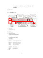
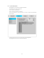
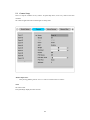
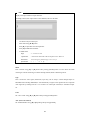
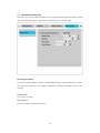
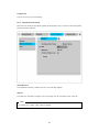
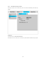
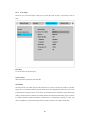
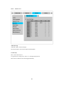
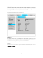
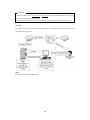
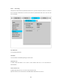
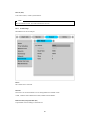
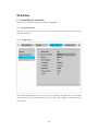
TritonHD User Guide
MD1600H
(v 1.1)
FCC Compliance Statement
Caution : Any changes or modifications in construction of this device which are not expressly
approved the party responsible for compliance could void the user's authority to operate the equipment.
NOTE : This equipment has been tested and found to comply with the limits for a Class A digital
device, pursuant to part 15 of the FCC Rules. These limits are designed to provide reasonable
protection against harmful interference when the equipment is operated in a commercial environment.
This equipment generates, uses, and can radiate radio frequency energy and, if not installed and used in
accordance with the instruction manual, may cause harmful interference to radio communications,
Operation of this equipment in a residential area is likely to cause harmful interference in which case
the user will be required to correct the interference at his own expense.
Warning
This is a class A product. In a domestic environment this product may cause radio interference in which
case the user may be required to take adequate measures
CAUTION
1.
Danger of explosion if battery is incorrectly replaced. Replace only with the same or equivalent type.
Disposal of used batteries according to the general recommendations against the environmental
pollution.
2. Do not throw the batteries into a fire, and do not heat, short-circuit or attempt to disassemble the
batteries.
3.
Do not attempt to recharge the batteries.
Important Notice
1. Do not place heavy objects on the top of the TritonHD.
2. TritonHD is for indoor use. It is not weatherproof. Use TritonHD with referring to its environmental
specifications (Temperature & Humidity). To clean the TritonHD, gently wipe the outside with a clean
dry cloth.
3. TritonHD uses AC power of 110V ~ 240V. Be cautious not to cause electric damages to TritonHD.
4. Be careful not to drop the TritonHD. Physical shocks may harm the product including internal HDD.
In addition, be sure the TritonHD is secured after installation.
5. TritonHD is made of metal. Therefore you can hurt human beings if you throw it to them or hit on
them. When installing TritonHD, be cautious to locate on safe places where children are unreachable.
6. If TritonHD does not operate properly, please contact the closest WEBGATE distributor for after sales
service. Tampering or disassembling the product will void the warranty.
7. Security surveillance laws may differ for each country. Therefore, please contact the local region first
to avoid any surveillance law violations.
The contents of this manual can be modified in accordance with Firmware or Software upgrade. In the
interest of continually improving products, approval & outlook can be modified without prior notice
Contents
Overview.................................................................................................................................... 7
1.
Introduction ......................................................................................................................... 7
2.
Description........................................................................................................................... 9
2.1.
Front Part ....................................................................................................................... 9
2.1.1.
2.2.
Rear Part .......................................................................................................................11
2.2.1.
2.3.
MD1600H front part................................................................................................. 9
MD1600H rear part .................................................................................................11
Summery of Installation................................................................................................. 12
Basic Structure ....................................................................................................................... 13
3.
Monitoring ......................................................................................................................... 13
3.1.
Basic Screen monitoring ................................................................................................ 13
3.2.
Single full screen mode.................................................................................................. 13
3.3.
Multi screen mode......................................................................................................... 13
3.4.
Manual Recording......................................................................................................... 14
3.5.
Auto Switch mode......................................................................................................... 14
3.5.1.
System Standard mode ........................................................................................... 15
3.5.2.
User Sequence mode .............................................................................................. 16
3.6.
Alarm mode ................................................................................................................. 17
3.7.
Zoom Screen mode ....................................................................................................... 17
3.8.
Pause Live screen.......................................................................................................... 17
3.9.
PTZ Control ................................................................................................................. 18
3.9.1.
Pan/Tilt Control ..................................................................................................... 18
3.9.2.
Zoom/Focus Control .............................................................................................. 18
3.9.3.
Utilizing Load Preset.............................................................................................. 18
3.9.4.
Utilizing Save Preset .............................................................................................. 19
3.9.5.
Utilizing Clear Preset ............................................................................................. 19
3.9.6.
Utilizing Auxiliary On ............................................................................................ 19
3.9.7.
Utilizing Auxiliary Off ........................................................................................... 19
3.10.
Relay control ............................................................................................................ 20
4
4.
3.11.
Screen Lock control ...................................................................................................... 20
3.12.
Utilizing Quad monitor .............................................................................................. 21
3.12.1.
Monitoring ............................................................................................................ 21
3.12.2.
Monitoring & Playback .......................................................................................... 22
Playback ............................................................................................................................ 23
4.1.
5.
Various Playback mode(Playback) .................................................................................. 23
4.1.1.
Playback on standard monitor (16 division)............................................................... 23
4.1.2.
Playback to divided Channel(4/9/16)........................................................................ 23
4.1.3.
Playback channel no. 5~16 at 4/9 channel division..................................................... 23
4.1.4.
Zoon Playback screen............................................................................................. 23
4.1.5.
Various Playback functions ..................................................................................... 24
4.2.
Search mode................................................................................................................. 25
4.3.
Copy / Backup / Delete.................................................................................................. 26
4.3.1.
Copy Image........................................................................................................... 26
4.3.2.
Backup Data.......................................................................................................... 27
4.3.3.
Delete Data ........................................................................................................... 28
Configuration..................................................................................................................... 29
5.1.
Quick Setup.................................................................................................................. 29
5.1.1.
Tim Set(Date/Time) ............................................................................................... 29
5.1.2.
Recording Setup .................................................................................................... 32
5.2.
Camera Setup ............................................................................................................... 34
5.3.
Manual Recording setup ................................................................................................ 37
5.4.
Schedule Recording Setup.............................................................................................. 38
5.4.1.
Global Setup ......................................................................................................... 38
5.4.2.
Setup by Channel................................................................................................... 39
5.5.
Alarm Recording Setup ................................................................................................. 42
5.5.1.
Sensor Setup ......................................................................................................... 42
5.5.2.
Motion Detection Setup .......................................................................................... 43
5.5.3.
Text Setup............................................................................................................. 46
5.5.4.
Global Alarm Recording ......................................................................................... 48
5.5.5.
Setup by Channel................................................................................................... 49
5.6.
Alarm Action Setup....................................................................................................... 51
5.6.1.
Schedule ............................................................................................................... 51
5
5.6.2.
Setup .................................................................................................................... 52
5.6.3.
System Alarm........................................................................................................ 53
5.7.
Monitor Setup............................................................................................................... 55
5.8.
System Setup................................................................................................................ 56
5.8.1.
Audio Setup .......................................................................................................... 56
5.8.2.
Time Schedule Setup.............................................................................................. 57
5.8.3.
Special Time ......................................................................................................... 58
5.8.4.
Security Setup ....................................................................................................... 59
5.8.5.
Disk Setup ............................................................................................................ 61
5.8.6.
Network Setup....................................................................................................... 62
5.8.7.
Serial Setup........................................................................................................... 67
5.8.8.
Status Overview..................................................................................................... 68
5.8.9.
Miscellaneous........................................................................................................ 69
5.9.
Disk Manager (Utility) .................................................................................................. 71
5.9.1.
Disk Manager ........................................................................................................ 72
5.9.2.
USB Utility ........................................................................................................... 74
Extension ................................................................................................................................ 76
6.
External device connection ................................................................................................. 76
6.1.
Using Text device ......................................................................................................... 76
6.1.1.
Setup in Text ......................................................................................................... 76
6.1.2.
Setup in RS232 menu of Serial Setup ....................................................................... 77
6.1.3.
Setup in Alarm Rec ................................................................................................ 78
6.1.4.
Setup in Recording................................................................................................. 79
6.2.
Using Keyboard............................................................................................................ 80
6.2.1.
Setup in COM1 menu of Serial Setup ....................................................................... 80
6.2.2.
Setup in PTZ menu of Serial Setup .......................................................................... 80
APPENDIX ............................................................................................................................... 81
#1.
Technical Specifications ................................................................................................ 82
#2.
Utilizing IP address in Local network .............................................................................. 86
#2.1.
Outline ................................................................................................................. 86
#2.2.
IP structure and Network grade................................................................................ 86
#2.3.
Network Class ....................................................................................................... 86
6
Overview
1. Introduction
TritonHD MD1600 Series is new conceptual DVR (Digital Video Recorder), which can record 16ch
ananlog video channel, Audio, Text & Alarm data etc simultaneously. Also, it upgrades video quality and
file size applying MPEG algorithm.
Quick Setup menu in TritonHD MD1600 Series makes possible to direct recording by only connection
between Power & CCTV video. Quick Setup menu is programmed to optimize video quality and
recording performance.
Also, TritonHD Series can extend the storage to maximum 8TB through IEEE 1394, eSATA and Network
Storage. For easy backup, it is easy to apply through user PC for HDD backup by FAT32 which is man
Window format type. Through 1 USB port, F/W upgrading and saing & retrieving setting value and copy
smalle size images is available.
<Note>
Extension through NVS04, IEEE 1394b will be supported later.
For the details, please contact to local distributor.
TritonHD MD1600 Series offers with Control Center Lite-D software. Control Center Lite-D S/W makes
available for easy setup, saving, playback via remote PC.
7
Main features
- It supports 16ch video
- Supports 4 ch bi-directional audio
- Supports recording, playback, network recording, network playback simultaneously (Pentaplex)
- Max. 480(MD1600H) ips recording speed
- Max. 480(MD1600H) ips real-time display speed
- Real time video surveilliance and recording via PC monitor & CCTV monitor
- Support Quad CCTV monitor(1 Normal, 3 Spot)
- Internal hardware Quad Splitter for analog channel
- Internal software multiplexer for 16channel division monitoring
(1 / 4 / 9 / 16 channel mode)
- Max. 8TB storage (External HDD expansion via IEEE 1394, eSATA, Network Storage)
- Various Recording & playback
- Independent file system for effective alarm data management
- Recording text data from ATM/POS in relevant to video data
- 16 sensor input & 4 alarm output
- MD searching (64 different specified MD area set, when Control Center operates)
- Text Searching (when Control Center operates)
- Internal CD-R/DVD-R backup
- PTZ control through RS232, RS485
- 32bit True Color graphic OSD menu for easy to use (Support Anti-Flicker)
- Support Static IP and DHCP, dynamic IP and xDSL, cable modem user
- Apply embedded Linux OS for reliability and efficiency
- Support Remote controller
- Firmware upgrading, Setup, retrieving through USB memory device
- Digital Water Mark
- Register max. 16 units TritonHD to Control Center Lite-D (PC user interfacer)
[Total 256 channel managements (16 TritonHD MD1600H x 16ch) through one S/W program]
<Note>
It supports only DVD backup. CD backup will be supported later.
For the details, please contact to local distributor.
<Note>
Extension through NVS04, IEEE 1394b will be supported later.
For the details, please contact to local distributor.
8
2. Description
2.1. Front Part
2.1.1. MD1600H front part
(1) Status LED
(2) Remote controller
(3) Power switch
receiver
(4) USB Interfacer
(5) Function buttons
(6) Channel button
(7) Menu & Directions
(1) Status LED
Power
: It indicates Power input, and light on at Power in.
Network
: Indicates Ethernet & communication status and twinkle as much as image delivery via
Ethernet.
Record
: Indicates video recording, and twinkle as much as image record
Play
: Indicates Playback mode and twinkle as many as image played at playback mode. Also,
twinkle as many as image delivered per second when it connects to Control Center LiteD Playback.
(2) Remote controller receiver
(3) Power Switch
It is the switch to Power On/Off. While the system Off, press longer than 5 sec. to display
admin/password input screen. Then input password to turn power off.
(4) USB Interface
Supply 1 USB port
9
(5) Function buttons
COPY
: Function to copy recorded images
In single monitoring mode, press the button to activate COPY menu
SEQ
: Function to diplay all video connected sequentially
Press more than 1 sec. to operate User Sequnce mode
MULTI
: Function to monitor multi video images in a screen((4/9/16 division channel)
SELECT
: Function to select video channel to control PTZ in Monitor model.
And function to select video channel to Copy/Backup/Delete in Playback mode.
ZOOM
: Zoom video image at 1 channel mode
RELAY
: Relay On/Off in Monitoring mode and return to original status when alarm pop-up
MON
: Function to select Monitor(1~4) to control
Press the button and monitor number to control relevant monitor
REC
: Function to start/stop recording by user
Start/Stop user recording according to set in advance
(6) Channel Select button
Select video channel when monitoring & playback
Below color LED on each channel button indicates the following status
GREEN
: Indicates Monitoring
BLINK
: indicates Alarming
(7) Menu & directional button
SEARCH
: Search the recorded image data at Playback mode
MENU
: PTZ Control or Setup Menu function
HELP
: Indicate each video data(Date, Channel name, HDD status etc.)
EXIT/LOCK : Move upper menu at Setup or Screen Lock
PALY
: Use as ENTER button during Menu operating, and use as PLAY button when
playback the recorded video data
Directonal
: Playback function at Playback mode, or else to move direction indicate
Key
REW
: Each press of the button will increase reverse playback speed gradually
(x1, x2, x4, x8, x16, x32, x64)
FFW
: Each press of the button will increase playback speed gradually
(x1, x2, x4, x8, x16, x32, x64)
PAUSE
: To pause Live/replaying
STOP
: To stop replaying
10
싱글/분할 모드에서 다음 채널 또는 분할 모드에 맞는 채널 그룹으로
전환 합니다.
2.2. Rear Part
2.2.1. MD1600H rear part
(3) Power connector
(4) Video input &
(7) FAN
Loop back
(6) Serial & DIO Port
(1) Audio In/Out
4 Audio input & 1 output
(2) Ehternet
(3) Power connector
(4) Video Input & Loop back
16 video input & Loop back terminal
(5) Video Output
4 Video output (1 Normal, 3Spot)
1 VGA output
(6) Serial & DIO port
Sensor In
: 16 Sensor input terminal block
Relay Out
: 4 Relay output terminal block
COM1
: RS232 9Pin D-Sub connector
COM2
: RS485 terminal block
STORAGE : RJ45 connector
IEE1394
: 2 connection port
eSATA
: 2 connection port
(5)
(7) FAN
11
Video
(1) Audi In/Out
(2) Ethernet
2.3. Summery of Installation
- Camera connection
- Monitor connection
- Ethernet connection (for remote connection)
- Audio connection
- Power connection & Operation
<Note>
Extension through NVS04, IEEE 1394b will be supported later.
For the details, please contact to local distributor.
12
Basic Structure
3. Monitoring
All analog video image channels connected to TritonHD is displayed to screen by Power connection. It is
to utilize all monitoring mode of TritonHD MD1600 series.
<Attention>
MD1600H support Quad monitor (1~4) and Monitor 1~4 supports all following functions.
Therefore, the following functions explains base on all Monitor 1~4.
3.1. Basic Screen monitoring
-
After Power connection, MD1600H
operates on automately.
-
It boots with LED on.
-
After booting, 16 channel screens are
displayed.
※ If there is user password set,
Password input window will be
displayed.
3.2. Single full screen mode
-
Press the channel number wanted.
-
Press [MULTI] button to return
divisional screen.
3.3. Multi screen mode
-
Press [MULTI] for multi channel
display.
-
Press [MULTI] button every time,
screen mode is changed to 4 / 9 / 16
division mode.
13
3.4. Manual Recording
By the press [REC] button for user recording, it records as long time as it set the time. It is prior to
Normal Rec, Event Rec. And it records by user recording set in disregard for any recording setup when
user recording starts.
3.5. Auto Switch mode
There are System Standard modes and User Defined mode in Auto Switch mode. And Users Sequence
mode operates by the press [SEQ] button 1 sec longer.
<Attention>
System stardard mode is capable to use when channel division is more than the number camera
connected. Namely, single at 2 or more cameras, 4 division modes at more than 5 cameras should be
connected. 16 division mode does not support auto switch function.
14
3.5.1. System Standard mode
-
By [SEQ] button, it can monitor auto switching of all channels.
-
Press [MENU] for the setting switching term.
-
Move to “Monitor” from OSD menu.
-
Press [▷] to move from “Monitor” to “Monitor 1”.
-
Select “Seq. Switching (sec)” and set value from 1 sec. to 60 sec. At OFF set, auto switch mode
does not operate.
-
Auto Switch mode can be set in every division mode by the press [SEQ] button.
-
Press [SEQ] button once more to leave from Auto Switch mode.
15
3.5.2. User Sequence mode
-
Press [SEQ] button longer than 1 sec.
-
User Sequence is to set User Sequence Configuration from “Monitor 1” in OSD menu.
<Attention>
1. User mode can define max. 16 channels.
2. The above picture defines 6 Sequence, and it is displayed in order as 4 division(1,2,3,4) Æ Full
screen(1)
Æ
4
division(5,6,7,8)
Æ
Full
division(9,10,11,12,13,14,15,16).
16
screen(5)
Æ
Full
screen(6)
Æ
9
3.6. Alarm mode
-
It can be set to Pop-up automatically relevant screen when alarming.
-
Set pop-up period can be set into “Alarm Pop-up (sec)” inferior to “Monitor” menu.
-
At the simultaneous alarming in several channels, it displays the division as many channel as
alarmed. For example, when 3 channels alarm, 4 divisions is displayed on screen. And press any
button to return orginal channel.
<Attention>
1. If Alarm Pop-up Hold (sec) set to Off, Alarm Pop-up will not operate.
2. If Alarm Pop-up Hold (sec) set to Keep, it does not return to previous screen before press any button.
3.7. Zoom Screen mode
-
At single full screen mode, press [ZOOM] to monitor 2x image size.
-
Default zoom screen locates to main center when press [ZOOM] button. Zoom image can shift
left-right in 18 steps and top-buttom in 12 steps.
-
Use directonal key button to screen move
-
Press [ZOOM] one more to return to original screen.
3.8. Pause Live screen
-
Live screen can pause like PlayBack.
-
Press [PAUSE] to pause live screen and press [▷] to return live screen.
17
3.9. PTZ Control
Connect PTZ controller to TritonHD and set relevant protocol from “Serial Setup” menu, then PTZ can
operate while monitoring live images.
-
Press [SELECT] button first.
-
Channel select icon is on the screen,
-
Shift to channel to control PTZ with directional key. (Press [SELECT] at single screen mode)
-
Press [MENU] at channel selection icon displayed to view PTZ (Pan/Tilt, Zoom/Focus, Load
Preset, Save Preset).
-
Select any wanted menu from them and press [ENTER].
3.9.1. Pan/Tilt Control
This menu is used to control Pan & Tilt function at real-time monitoring mode.
-
Press [SELECT] button and select Channel.
-
Press [MENU], then select ‘Pan/Tilt’ from OSD.
-
Control Pan/Tilt through directional key at front part.
3.9.2. Zoom/Focus Control
This menu is used to control Zoom & Focus function at real-time monitoring mode.
-
Press [SELECT] button and select Channel.
-
Press [MENU], then select ‘Zoom/ Focus’ from OSD.
-
Control Zoom/Focus through directional key at front part.
3.9.3. Utilizing Load Preset
This menu is used to shift to Preset Set at real-time monitoring mode.
-
Press [SELECT] button and select Channel.
-
Press [MENU], then select ‘Load Preset’ from OSD.
-
Press relevant Number button of Preset set.
18
3.9.4. Utilizing Save Preset
This menu is used to set new Preset at real-time monitoring mode.
-
Control camera location using ‘Pan/Tilt’ and ‘Zoom/Focus’ menu.
-
Press [SELECT] button and select Channel.
-
Press [MENU], then select ‘Save Preset’ from OSD.
-
Press relevant Number button to set in Preset.
3.9.5. Utilizing Clear Preset
This menu is used to initialize Preset at real-time monitoring mode.
-
Press [SELECT] button and select Channel.
-
Press [MENU], then select ‘Clear Preset’ from OSD
-
Press relevant Number button to initialize Preset.
3.9.6. Utilizing Auxiliary On
This menu is used to utilize specific function in PTZ device at real-time monitoring mode.
-
Press [SELECT] button and select Channel.
-
Press [MENU], then select “Auxiliary On” from OSD
-
Press relevant Number button of specific function (Aux function is available to max 16 functions.)
3.9.7. Utilizing Auxiliary Off
This menu is used to stop operation of specific function of PTZ device.
19
3.10. Relay control
The function to Relay On/Off. (MD1600H supports 4 Relay Output.)
-
Press [RELAY] button to display “Relay On” icon on screen.
-
Then Relay Out signal is out by pressing the relevant number of Relay among 1~4 number button.
-
Press [RELAY] to Relay Off.
-
Display “Relay On” icon while Relay On is working.
-
Then “Relay Off” icon is displayed on when press [RELAY] button once more.
-
Rress relevant Relay button to Relay Off.
3.11. Screen Lock control
The function to prevent unauthorized user operating the menu at will.
Set “User Password” first to use this function.
Press [EXIT/LOCK] button over 3 sec. to operate Lock mode with message “Screen Locked” on the
bottom of screen. When “User Password” is Off, the message “Enable user password first” is on the
screen.
At the Lock mode, any button does not work. It must release to operate function button. At Lock mode,
20
window for user password input will be displayed at any button press. And Lock mode will be released
with correct password input.
3.12. Utilizing Quad monitor
3.12.1. Monitoring
Monitor 1 monitors several video channels, and Monitor 2 is for bigger screen of channel 1. Also Monitor
3 for Sequence mode and Monitor 4 is capable of monitoring Alarm Pop-up images. Every Monitor 1~4
can be set in following conditions separately.
Monitor 1
Monitor 2
Monitor 3
Monitor 4
Multi Monitor
Single Monitor
Sequence Monitor
Alarm Pop-up Monitor
Single Monitor
Sequence Monitor
Alarm Pop-up Monitor
Sequence Monitor
Sequence Monitor
Alarm Pop-up Monitor
Multi Monitor
Single Monitor
Alarm Pop-up Monitor
Multi Monitor
Single Monitor
Sequence Monitor
21
3.12.2. Monitoring & Playback
Monitor 1~4 are capable of searching several video/playback in single & divided sreen. Namely, several
channels can be monitored and playback separately and simultaneously. But Playback can be monitored
in 1 monitor among Monitor 1~4, and the rest 3 monitors for monitoring.
22
4. Playback
4.1. Various Playback mode (Playback)
4.1.1. Playback on standard monitor (16 division)
-
Press Playback button [▷] at Monitoring mode.
-
It playback images with initial 1x speed.
<Attention>
At Monitor mode, Playback buttom will play the recorded image from Channel 1.
Namely, it will always start playback of channel 1 from 30sec. ago.
At the time, the data of image will be shown at the bottom of screen. And the one on top indicates
images for 30 min. and the bottom indicates 12hrs.
It also playback video images of the channel that input the wanted channel number.
4.1.2. Playback to divided Channel(4/9/16)
-
Press [MULTI] button at single playback screen mode. (Pressing [MULTI] button every time, it is
changed 4, 9 16 channel division.)
-
Channel 1~4 images is playback in 4 channel division.
-
Select channel number to playback single channel playback mode.
4.1.3. Playback channel no. 5~16 at 4/9 channel division
Press [SEQ] button or playback the wanted channel on divisional channel.
-
Press [SELECT] button at 4/9 divisional channel.
-
Select divisional channel by direction key.
-
Playback the images to the location appoint for selected channel number.
4.1.4. Zoon Playback screen
-
Press [ZOOM] button at single screen playback mode to displays 2x zoom playback image.
-
Pressing [ZOOM] button will locate zoomed images to the center of screen. Zoomed image can
shift left-right & top-bottom at 10 and 7 grades.
-
Screen shift is carried by direction key button.
-
Press [ZOOM] one more to return original screen mode.
23
4.1.5. Various Playback functions
▷ (PLAY)
: Playback 1x speed.
Press [▷]playback button at single monitor mode will playback recorded
images of monitoring channel.
Press [▷]playback button at multi monitor mode will always playback
recorded images of no. 1 channel.
When the execute playback by pressing [▷] playback button, it playback from
the time when user connects to playback lately.
STOP
: Stop Playback.
PAUSE
: Pause Playback.
FFW
: Change Playback speed at every button pressing.(x1, x2, x4, x8, x16, x32,
x64)
REW
: Reverse playback speed at every button pressing. (x1, x2, x4, x8, x16, x32,
x64)
If press REW button at Monitor mode, it will reverse playback from the last
recorded section, and it will forward play from 1 min. previous if press FFW
button.
STEP FORWARD
: Playback by each frame with [▷, PLAY] or [, FAST FORWARD] button at
PAUSE. Press [, STOP] and then [▷, PLAY] or [, FAST FORWARD] to
return normal playback.
STEP REWIND
: At PAUSE, press [, FAST REWIND] to playback one by one fram in
reverse. To return to normal playback, press [, STOP] and then [▷, PLAY]
or [, FAST FORWARD].
24
4.2. Search mode
This menu is to playback specific time data from the time frame and searching log at Playback mode.
From for the time to start recorded data, To indicates the last time. Select From/To and press [ENTER] to
move to the relevant time.
<Order of Button Input>
-
Press [SEARCH] at Playback mode.
-
Input Date/Time or select relevant Log from Log Browser.
-
Press [▷] button.
-
Playback searched image.
-
Press [EXIT] to exit from Search mode.
<Note> How to use Log Browser
1. Shift each page with Left/Right key.
2. Shift to previous Log block by Up key at first page and first log.
3. Shift next Log block with Down key at last page and last Log.
25
4.3. Copy / Backup / Delete
This menu describes how to copy/backup/delete recorded images.
-
Press [SELECT] and [MENU] in order and Playback mode.
4.3.1. Copy Image
Use USB Memory Stick etc to copy selected channel images in some part.
Time
Slect the range of Copy. Range of image can set 1sec.~1hrs. from present playback location.
Select Disk
Slect the target of Copy.
26
4.3.2. Backup Data
Start Date & Time / End Date & Time
Select the range of backup.
Select Disk
Select the disk to use backup device.
<Note>
Uncompleted backup file 100% can not be played normally in PC
<Note>
It does not support USB device as backup.
It supports CD-R/DVD-R, and over (CD-R Media 700MB / DVD R Media 4G) in CD-R Media.
It creates re4 in HDD re4, in CD-R vfs4.
<Note>
It supports only DVD backup. CD backup will be supported later.
For the details, please contact to local distributor.
27
4.3.3. Delete Data
The menu to delete specific rage of data in present HDD recorded. Delected data is limited to present
HDD used, and it does not affect to backup disk.
The range of delete data is from oldest data to the data that the time selected.
<Note>
The size of block in TritonHD file system is 64MB and delect data is carried in block. So Delete data
does not define the accurate time data.
28
5. Configuration
5.1. Quick Setup
There are 3 methods in Video recording setup - Quick Setup, Recording, Alarm Recording menu. Quick
Setup is the menut to set recording easily in same condition of all analog channels. Recording is to set
recording in more various conditions by time period or channel. Alarm Recording is to set the recording
with alarm. Also, Quick Setup includes Time Set menu.
5.1.1. Tim Set(Date/Time)
Factory set of TritonHD comes to “UTC 00:00 Dublin” as Time set.
First set in TritonHD setup is to set time of relevant area. Time Set is very important to protect recorded
data.
Change of the time of TritonHD[Date/Time] can influence to images recording. And it could make the
HDD format.
<Button Input order>
-
Press [MENU] at the front of TritonHD
-
Shift to “Quick Setup” menu
-
Shift to “Date/Time” of “Quick Setup” using direction key at Front panel, and press [ENTER]
button.
-
Normal operation of button in order will make the display following screen.
-
Press [ENTER] to shift to each inferior menu after select menu with direction key.
29
Time Zone
Select the times using left-right directional key from TritonHD front. Every time pressing direction
changes the time zone. (Press [EXIT] to return to previous menu. It is as same as OSD menu.)
Daylight Saving (Summer Time applied)
This menu is linked to Time zone set menu. Namely, it is activated when selected summer time zone is set
from Tim Zone set menu. Summer Time Zone is programmed to apply the time zone from existing MS
Windows. At these stages, when TritonHD is installed to DST area apply, set Left & Right key whether it
applies relevant Summer Time.
Sync with NTP
Select whether synchronize NTP (Network Time Protocol) and Time.
<Note>
Refer to “NTP Settings”from Network Setup in detail relate to NTP.
Time Format
30
Selet the method of Time Format. Using Legt-Right key set Time Formate “MM/DD/YYYY” or
“YYYY/MM/DD”.
Date/Time
Using Left, Right key will shift Year, Month, Date menu, and select each menu with Upper & Lower
button.
Apply Date/Time
To apply Date/Time value, press “Apply Date/Time” button to display the following window.
<Note>
Other setup can be saved automatically by closing setup menu completely, but “Date” & “Time” does
not because it can affect HDD recording File System critically. To save and apply changed data, it must
press [Apply Date/Time] button manually..
31
5.1.2. Recording Setup
Quick Setup is to set same conditions to all analog channels in every hour.
<Button Input>
-
Select “Recording” menu inferior to “Quick Setup”.
Configuration Status
It just indicates the setup status of recording only. If user sets recording condition to Quick Setup, it is
indicated to “Macro Setup” and “Custom Setup” when any set has changed from Recording menu.
<Note>
“Macro Setup” indicates the same of schedule recording of all channels.
32
Channel Status
Set whether it activates all analog channels. Defult value is “On”.
Recording Speed/Quality
There are all 5 setup conditions. (No Rec./Low/Standard/High/Custom).
The conditional Setup except “Custom” comes to auto synchronize with “Speed (ips)”and “Quality”,
Quality can set the each separately. At the setup condition of “Alarm Recording”, “Standard”와 “Pre/Post
Alarm” is set to each 1 second.
Resolution
Recording resolution of all cameras [CIF /Half D1/ Full D1].
Audio Recording
It sets Audio recording. In case of Audion recording set to “On”, “Audio Synch with” is set to “All” and it
synchronizes all channels when playback.
Apply
To apply Setup, press “Apply” button, and move to previous menu pressing [EXIT] to start TritonHD
recording based on the setup condition of recording.
33
5.2. Camera Setup
This is to setup the condition of every camera. At Quick Setup menu, it sets every camera to the same
condition.
Set values are applied in same at monitoring & recording mode.
<Button Input order>
-
After pressing [MENU], shift to “Cam # 1~Cam #16” inferior menu of “Camera”.
Name
Set Camera name.
Press [ENTER] to display the letter set menu.
34
<TIP>
Display Letter input window to input characters.
According to menu, letter input window can be different, but Set is the same.
-
Use direction key for letter input.
-
Select letter using [▲/▼] button.
-
Press [►] to input after select the input letter.
-
Press [◄] to Shift back and delete.
-
Avaiable letters
Digit
:1234567890
Capital letter
:AB C DE F GH I J K LM N O PQR STUVWXYZ
Small letter
:abcdefghijklmnopqrstuvwxyz
Special letter
:( ) - . $ # @
Status
Press “On/Off” using [◄] or [►] button after pressing [ENTER] button. To raise frame rate while
recording or network monitoring, turn off the unusing channels, Refer to Recording section.
Type
This is shown the video signal (NTSC/PAL) input only, and its setup is carried through Jumper in
MD1600H. When booting MD1600H, it will automatically recognize video signal from first recognized
video signal set by examing from ch 1 to 16. If there is no video input connection, it will follow Jumper
set.
Color
Set “Color / B/W” using [◄] or [►] button after pressing [ENTER] button.
AGC (Auto Gain Control)
Set “Enable/Disable” using [◄] or [►] buttong after pressing [ENTER].
35
Brightness/Contrast
Select the value from “–9” and “+9” using [◄] or [►] buttong after pressing [ENTER].
Covert
Covert On will hide the channel at Monitoring mode.
Select “A / B / Both / Off” using [◄] or [►] buttong after pressing [ENTER].
PTZ Home/PTZ Idle Time
Shift to Preset assigned if it has no movement in certain time while PTZ control
Set Preset number and Time using [◄] or [►] buttong after pressing [ENTER].
PTZ Port
Set PTZ port connected to relevant channel by using [◄] or [►] buttong after pressing [ENTER].
Address
When press [ENTER], Letter Input window will be displayed to set base address of PTZ device.
36
5.3. Manual Recording setup
This menu is to set video recording condition by user when pressing [REC] button. If manual recording
starts, Normal Rec & Event Rec is ingored and it records based on user recording setup.
Recording Speed/Quality
There are all 4 setup conditions. (No Rec/Low/Standard/High/Custom). Setup condition except “Custom”
will synchronize “Speed (ips)” and “Quality” automatically, Speed(ips) and Quality can be set each
separately.
Pre Alarm (sec)
It can set max. 5 seconds.
Post Alarm (sec)
It can set Continuous or maximum 60 seconds.
37
<Note>
1. In case of set ‘No Rec.’ in Schedule Rec., it records as a set of Pre Alarm. While Schedule
Recording, it records Pre Alarm section in speed(ips) of a set Schedule Rec.
2. When Post Alarm is set to Latched, it maintains user recording continuously till the stop
pressing [REC] button by user.
5.4. Schedule Recording Setup
This recording is to set the recording conditions by Channel and Time schedule. After “Quick Setup” set,
it is changed to new set value from previous value set if the set is changed at this manu.
5.4.1. Global Setup
It is similar to Quick Setup recording, and it set to same conditions of all analog channels at every hours.
38
<Note>
1. The difference of recording setup in Quick Setup is that there is no audio recording setup, and sets
whether Special Time Recrding & Event Recording sets or not.
2. What Alarm Recording Off is set, Alarm Rec. menu is not available. To set Alarm Rec. menu, Alarm
Recording of Recording menu should be set to “On” and press “Apply” to complete setup.
4. Refer to the following Setup by Channel how to set in detail.
5.4.2. Setup by Channel
Time Schedule
It sets recording condition based on every time schedule. Time period can be set 4 districted areas, Full
Time, Weekday (Day)/Weekday (Night)/Weekend (Day)/Weekend (Night). Day & Night, Weekday &
Weekend can be set from “System” menu.
39
<Time Schedule Setup>
Shift to“System” menu to set Time Schedule.
Weekday Start/End
Set Time zone from Monday to Sunday using Left, Right key button. The unset zoon can be set to
Weekend time zone.
Day Start/End
Set Day time zone using Up, Down button. The unset zoon can be set to Night time zone.
Recording Speed/Quality
There are all 5 setup conditions. (No Rec./Low/Standard/High/Custom).
Setup condition except “Custom” will synchronize “Speed (ips)” and “Quality” automatically,Speed(ips)
and Quality can be set each separately.
40
Resolution
There are all 3 conditions. (CIF/HALF/D1)
At this menu, resolution set is applied to every User recording, Event recording.
-
CIF : 360x240 @ NTSC, 360x288 @ PAL
-
HALF : 720x240 @ NTSC, 720x288 @ PAL (HALF D1)
-
D1 : 720x480 @ NTSC, 720x576@ PAL (FULL D1)
Special Time Recording
This menu is to differenciate recording conditions by setup of specific time zone. Namely, if it sets to day
time in workday, it can record according to 2 type setup condition. Specific time sets from ‘System’ menu.
There are 5 setup conditions; No Rec./Low/Standard/High/Same as above (Apply same value with
“Recording Speed/Quality” value. ).
< Specific Time Zone Setup >
Shift to“System” menu to set Specific Time zone.
Max. 4 specific time zones can be set.
41
Event Recording
After pressing [ENTER] button, set “On/Off” using [◄] or [►] button. Detailed Alarm recording
conditions sets from “Alarm Recording” menu. Here only can set recording according to alarm recording
setup.
5.5. Alarm Recording Setup
This menu is to set Alarm Recording condition. After setup Recording condition, “Event recording” menu
from “Recording” must be “On” to setup Alarm recording in TritonHD. Also, before setup Alarm
recording, “Alarm Source” must be set.
5.5.1. Sensor Setup
This menu is to set existence of sensor and type of sensor. It support 2 type sensors, Normal Open(N.O.)
과 Normal Close(N.C.)
Global
It set all sensors same together. After select among Off/N.O./N.C., and press “Apply” to activate.
42
Configuration
It can set 16 sensors (S1~S16) separately.
5.5.2. Motion Detection Setup
This menu is to set MD of each channel. Global sets all channels (Cam #1~Cam#16) in the same together,
and setup can differ separately.
Motion Detection
It sets 4 different sensitivity of MD; Off, Lowest, Low, Std, High, Highest.
MD Area
It sets MD zone. 64 (width 8 x height 8) zone is selected by “Set All” and release it with “Clear All”.
<Note>
To set Global, press “Apply”. Other will be not applied.
43
5.5.2.1.
Motion Detection Setup by Channel
MD setup by channel is same as Global setup. And it can set MD zone additionally when MD sets by
channel.
Custom Area
It sets MD zone by user NTSC 22x15, PAL 22x18
First default value is set to “Select All”. If “Custom Area” pressed, Window for MD zone setup is opened.
44
< MD Zone Setup >
It can set MD zone by user directly.
If “Custom Area” is pressed, sell NTSC 22x15, PAL 22x18 for setup is displayed. Selected MD zone
is in grey color. To select MD zone, use direction key for the wanted zone and press“ENTER” to
apply. After selection, press “EXIT” to return previous menu.
45
5.5.3. Text Setup
This menu is to set text data input. It has to be set COM1 part from “System -> Serial Setup” menu on
OSD.
Recording
It is On or Off to save the Text input.
Sync Text With
Select the channel synchronize with Text data.
Seek Header
It has the various type of data input from the external device (Access Control, POS, ATM etc). Like Star
Finger 007, it is not needed when the protocol of these device have implemented on the device. If not, this
is the parameter to analyze how the one of data is constructed from the text data that is input continuously.
Namely, all data has the first and the end. Header indicates the information that already inserts to inform
its starting. Therefore, Header information is defined here to acknowledge its starting of a data. The
reason of 2 Header is to detect maximum 2 data out because each device can output various datas.
46
Delimiter
Value of Delimiter can be different according to every device. Refer to their manual or inquire it to
purchasing stores of its model.
Timeout (ms)
Following lines defined here means maximum number of text line from one data. Even if there is
standized data, there can be a short and long data. For example, there are 3 lines to write names on ATM.
But some may need only First name & Last name to register. Which it means requires only 1 shorter than
other ATM users. It is to decide the last line of the one data register as final complete data to save after an
hour’s consideration of register later because TritonHD can not recognize it automatically.
Lines
It defines how maximum many lines is structed by a data.
47
5.5.4. Global Alarm Recording
Set all analogue channels in same condition.
Sensor/MD
Set synchronizing with Sensor/MD.
Pairing means 1:1 synchronization between the channel and Sensor/MD.
Text
When set “On”, it deals text input of relevant channe as Alarm Event and is saved.
<Note>
1. To apply Global setup, press “Apply” button.
2. Refer to following Setup by channel for the details.
48
5.5.5. Setup by Channel
Alarm Source (*=All)
-
Through Alarm Source, 4 Sensors and 1 MD, Text input is selectable.
-
Selection of Sensor is set by pressing relevant number button.
-
Selection of MD, Text can be On/Off by direcitional key.
-
Select Preset of PTZ by relevant Alarm input.
<Note>
1. * : Press ▷ button.
2. – or # : Press number 0 button.
Recording Speed/Quality
There are all 4 conditional setup (No Rec/Low/Standard/High/Custom).
Except “Custom”, Setup condition will synchronize “Speed (ips)” and “Quality” automatically, Speed
(ips) and Quality can be set each separately.
Pre Alarm (sec)
It can set max. 5 second.
49
Post Alarm (sec)
It can set max. 60 seconds.
<Note>
1. In case of set ‘No Rec.’ in Schedule Rec., it records as a set of Pre Alarm. While Schedule
Recording, it records Pre Alarm section in speed (ips) of a set Schedule Rec.
2. When Post Alarm is set to Latched, it maintains user recording continuously till the stop
pressing [REC] button by user.
Alarm Recording Status
It can check ON/OFF of Alarm Recording menu in Schedule Recording setup.
50
5.6. Alarm Action Setup
According each Time schedule, it sets Relay action. It sets to 5 different time period, Full Time,
Weekday(Day), Weekday(Night), Weekend(Day), Weekend(Night). After Schedule setup, it sets Relay,
Buzzer, Email etc to operate Alarm action.
5.6.1. Schedule
Select Action Source
Sensor and MD can be set max 4 or ANY for Relay1~Relay4, Buzzer, E-mail. Video Loss and Text can be
set On/Off. Selection of Sensor/MD is done by pressing relevant number button.
<Note>
1. ANY : Press ▷ button.
Special Time
It selects whether it apply specific time period that is set.
<Note>
1. Global Setup is to apply Time Schedule to all at same.
2. Press “Apply” to apply Global setup.
51
5.6.2. Setup
Relay Configuration
Set the use or not for R1~R4.
Buzzer
Set the use of Buzzer or not.
E-mail Addr.
Input E-mail address to inform Alarm.
Sender Addr.
Input “Sender” address in the typr of who@where.
Mail Duration (min)
E-mail notification is to send message in terms of Mail Duration set, but not every time that Alarm is
occurred. It can be set from 1 to 30 minutes.
52
<Note>
Network setup is set to DNS for E-mail notification.
5.6.3. System Alarm
5.6.3.1.
System Alarm Setup
It is to set ON/OFF of Alarm for the notification of system faulty.
HDD Fail
Alarm action is operated when HDD disconneced or abnormal action.
HDD Almost Full
It operates alarm action when connected HDD is almost full.
Fan Fail
It operates Alarm action when malfunction of FAN connected to TritonHD.
53
Password Fail
It operates Alarm when wrong User or Admin password input.
WRS Reg. Fail
It operates Alarm when disconnection of WRS.
5.6.3.2.
Alarm Method Setup
It is to set ON/OFF of Alarm when system alarm is occurred.
Warning Message
When setup this menu, it display warning message through pop-up.
Warning Message remains On always..
Beep
When set this menu, it sounds Beep.
Send E-Mail
When this menu is sest, it sends email to the address input.
Select Relay
It operates Relay selected from 1~4 relay.
54
5.7. Monitor Setup
It sets the monitor for the display of video from monitor 1 to 4. Available meni for monitor 1~4 are all
same.
Alarm Pop-up (sec)
It sets auto Pop-up display for the alarm. Pop-up display time can be set from 5~10 second. If it sets to
“Keep”, it keeps to display Pop-up image and press any button to release Keep mode.
Seq. Switching (sec)
It sets auto switching from 1 to 60 seconds.
Anti-Flicker OSD
It can On/Off Anti-Flicker OSD menu. When it is On, it soften Menu and Text on screen and no trembling.
But when it is Off, the letter will be cleared and trembles. Set On/Off based on the condition of the user’s
monitor.
<Note>
If no. 2 channel pop-up again within a few time passed after no. 1 channel pop-up, it is changed to 4
division and shows 1, 2 channels. And the holding time from the last pop-up time is extended
automatically. (Max. 8channels)
55
User Sequence Configuration
It can edit Auto transmit function for user mode.
<Attention>
1. It can define all 16 user mode.
2. The picture for example defines 6 Sequences in order as shown 4 division(1,2,3,4) Æ Full mode(1)
Æ 4 divisions(5,6,7,8) Æ Full mode(5) Æ Full mode(8) Æ 9 divisions(9,10,11,12,13,14,15,16).
5.8. System Setup
5.8.1. Audio Setup
MD1600H supports 4channel Audio recording. But it operates with any channel when video playback.
Recording
It sets whether Audio records or not.
Audio Gain
It is possible to set from -7 to +8.
Sync Audio with
When playback recorded image, it sets which it works together.
56
5.8.2. Time Schedule Setup
It sets the time period from Week & Weekend, Day and Night.
Weekday Start/End
Using Left, Right key sets the time period from Weekday. Other unassigned time is for the Weekend.
Day Start/End
Using Up, Down button sets Day time period. Other time is applicable to the Night time.
57
5.8.3. Special Time
It can set another specific time zone in each time zone (Week day, Week night, Weekend day and night),
For example, various conditions setting separately such as mealtime or meeting time is applicable.
It used for the set of regular exceptial time. Max. 4 different specific time can set.
Exception Days
It used for the setup of irregular exceptional time, max. 30 time zones.
-
Start Date&Time : Set Starting time.
-
Duration : Set an interval of Exceptional time.
-
Profile : Set the value of exceptional time zone.
(No Rec, Week day & night, Weekend day & night)
58
5.8.4. Security Setup
5.8.4.1.
Local Password
User Password
It is only capable of monitoring and playback only with user registery. Default set is “1111”.
Admin Password
Authorized administrator can control every function. Default set is “9999”.
59
5.8.4.2.
Remote Users
Admin ID setup
Admin ID “admin” cannot be changed.
Password of admin is set and has all rights and unchangeable.
User ID setup
Max. 10 user’s ID can be set.
To register the user, change Use’s value to “Y” and input ID & password.
Basic value is available for all monitoring/playback/Relay.
60
5.8.5. Disk Setup
Auto Deletion
When no HDD space left for recording, it deletes the recorded data automatically.
Backup Reminder
This menu is to inform backup time by everyday, every week, every month.
Day/Date/Time
It applies the value of setup differently according to value of “Backup Reminder”.
Block PlayBack
This menu is to playback the recorded images from HDD in limited time. It can set from Day 1 to 31.
61
5.8.6. Network Setup
There are 5 Sub menus. ; Network, xDSL, WRS, Port Setting, NTP Setting
5.8.6.1.
Network
When TritonHD connects to network, it is to set relevant network information.
Type
It sets the type (Ethernet/xDSL) of network line connected to TritonHD. It sets ‘Ethernet’ at the
connection of network through leased line, Cable model or LAN based connection.
It sets to ‘xDSL’ when TritonHD is connected to xDSL line of PPPoE method. But it sets to ‘Ethernet’ if
it is not PPPoE method even if it is xDSL line.
DHCP
DHCP (Dynamic Host Configuration Protocol) is to manage HOST address in network. All Host connect
to LAN using such network protocol can jointly own public IP address that is limited. Another means that
all Host allocates public IP address temporary from DHCP server. If LAN has DHCP server and activates
DHCP menu, DHCP server allocates public IP address to TritonHD.
62
‘DHCP’ is used in LAN that DHCP server works. Nornally, in mid or large scale, it operates DHCP server
via LAN but generally use NAT (Network Address Translation) function via HUB in small.
IP Address, NetMask, and Gateway Address, DNS, Port, Bandwidth limit
It sets IP address, Network Mask, Broadcast address, Gateway , DNS address, and Port, Bandwidth limit.
5.8.6.2.
xDSL
When TritonHD is with xDSL line and PPPoE method, ID & Password should be setup.
User ID/Password
Set ID & Password for TritonHD in xDSL connection.
Status
It indicates the connection of TritonHD.
63
5.8.6.3.
WRS
If TritonHD is connected to Cable modem or xDSL modem, IP address is changed at every connection to
ISP. In this case, changed IP address can not be known. If TritonHD using static IP register into WRS
server, changed IP address can be known easily when it connects to TritonHD.
To register Static IP to WRS, please refer the following to set.
WRS Interval
For continuous registery, register inverval should be set to ‘WRS Interval’. According to set value of
static IP address, it renews the information in WRS server regularly. If user registers the interval ‘0’ or
TritonHD does not transmit any data for 2 days, the data is removed from WRS.
WRS URL
This menu is to set server address to register. WRS addresses that WebGate operates
210.116.114.37 or mycam.to.
64
now are
<Attention>
1. If domain address such as 210.116.114.37 or mycam.to is input in WRS URL, DNS server IP should
be noted on “System Æ Network Æ DNS1”.
2. DHCP line such as Cable/DSL receives DNS address automatically and does not require an entry.
Group ID
Group ID is to set group name that TritonHD registered. It recommends uneasy Group name to avoid
same Group name registered.
Status
It indicates the status of TritonHD registry.
65
5.8.6.4.
NTP Setting
NTP(Network Time Protocol) synchronizes the time of every devices connected to network. It consists of
Server that offers standard time on network, and Client for synchronization that receives the time from
server connected.
Sync With NTP
It can On/Off NTP function.
NTP Mode
It sets NTP mode of TritonHD operating in Client or both.
NTP Server Loc.
It enables when NTP Mode is set to Client. It sests whether NTP server is in Local Network or
Internet(Public).
NTP Local Server IP
It enables when NTP Server Loc. is set to Local, and set Server IP.
Input IP of NTP server in local network or TritonHD IP that NTP mode is set to Server.
66
Interval (min)
It sets interval (min.) of Time synchronization.
<Note>
When NTP Mode is Client, Sync with NTP must be set to On.
5.8.7. Serial Setup
MD1600H can set all 4 COM port.
Device
Set external device connected.
Interface
This menu is to set which interface can use among RS485 from “RS485” menu.
COM1, COM3 is fixed to RS232 and COM2, COM4 is fixed to RS485.
Baud rate/Parity/Stop (bit)/Data (bit)
In put suitable value according to external device.
67
5.8.8. Status Overview
It shows status & temperature of HDD relevant to video recording and Fan speed.
Earliest / Latest Recording
It shows intial starting time and last time of the recorded file.
Disk Capacity
It shows total HDD capacity installed.
Used Space
It shows HDD capacity recordable.
HDD Temp
It shows HDD temperature installed.
HDD SMART
It indicated HDD status installed in GOOD & BAD.
68
FAN RPM
It shows FAN speed installed in TritonHD.
5.8.9. Miscellaneous
<Order of Button input>
- After press [MENU] button, move to “Miscellaneous” inferior to “System”.
Remote Control ID
Max 16 controller ID can set up and contril via 1 remote controller. Set to Off if it is not used.
<How to register Remote Controller>
-
Face Remote controller toward TritonHD.
-
Press “ID” button on controller when TritonHD is responding.
-
If ID of Controller does match with ID of TritonHD, all Alarm LED of TritonHD is ON and sounds.
-
It is capable to use after ID match.
-
Refer to “Installation Guide” for the details.
69
Keyboard Control Addr
This menu is to set Keyboard address when all functions of TritonHD is controllered by Keyboard button.
Default value is set to “1”. If several TritonHDs connect to a keyboard, 32 channel can clash. Then set to
the other address of keyboard.
DVR ID
This menu is set the name of TritonHD.
Record No Video
If this is “On”, it records video image which is not input.
Interpolation
Interpolation On/Off
The “Interpolation mode” only runs when the recording resolution is in Full D1.
In case of enable it, the Full D1 image with Pause condition the picture will have less tremor.
Language
OSD menu is supported in multi languages. Select the wanted language.
H/W Version
It indicates H/W version of the system.
S/W Version
It indicates F/W version of the system.
MAC Address
It indicates Mac address of the system.
Serial Number
It indicates Serial number of the system.
System Logs
It is used to view System Log. Press “System Logs” button to view System Logs.
Reset Values
It is used to set system to initial factory setup. Press “Reset Values” button to set factory setup mode.
70
5.9. Disk Manager (Utility)
It explains adding or formatting internal, external Hard disk. TritonHD supports various external storage.
< Order of Button input>
- After press [MENU] button, move to “Utility” inferior to “System”.
71
5.9.1. Disk Manager
Installed Hard disk is automatically recognized.
Select Disk
Select disk to set.
Action
Select wanted work among the menus, “Add/Remove/ Confirm Removed/Add used”.
[Add]
: Add Disk. Use disk that there is no partion table. Partion table can be removed
from PC. When adding HDD, “Alarm Partition” menu is activated to set up.
“Alarm Partition” indicates dividing 1 HDD to Recording part and Alarm
Recording part.
[Remove]
: Remove present HDD used logically. Later it is possible to use it through ‘Add
used’ without formatting.
[Confirm Removed]
: Complete removal from the lists when it remains in the list after HDD removal
from TritonHD.
[Add used]
: Adding HDD again without formatting that is used
< Compatible File System> Disk that is used in TritonHD reusable again
72
without deleting data through Add Used.
FAT32 Format
FAT32 Format when connecting external Hard disk.
Execute FAT32 Format for Backup/Copy in partition of under 250GB. For
execution of FAT32 format, creat partition through disk manager of PC first. If
HDD size is over 250GB, create several partitions smaller than 250GB and
execute FAT32 formate in each partition.
Type
Followings indicate the type of HDD.
[R]
: It is recordable by completion of HDD format.
[V]
: It is being connected and formatted to TritonHD file system. It is changed to [R] through
‘Add used’. It does not ‘Format’.
[F]
: It is connected, but it is required to change to [R] using ‘Add’ due to the difference of File
System in TritonHD (FAT/FAT32 File System).
[X]
: HDD connection cable is not connected or problem in HDD. Check the cable and reboot
the system or remove it from the list executing ‘Confirm Removed’.
[C]
: Usable when backup to external CD-Writer
< Compatible File System >
How to Use.
-
After upgrading DVR, HDD that recorded in previous version is indicated to [V] in Disk Manager.
-
Select HDD in ‘Select Disk’.
-
Press ‘Apply’ after selection of ‘Add Used’ at Action.
-
Press OK at ‘NOTICE - Disk reused for recording’.
-
Convert with messege ‘Converting files from old version may take a few minutes’ at lower screen.
-
If Type is changed to [R], it indicates HDD usable with completion.
Attention
-
If it upgrades system, HDD that is recorded in previous version is signed [V]. It must do Add Used
for the reusable.
-
Based on HDD size, it can take 10 second to a few minutes to Add Used.
-
Playback from HDD recorded in previous version can not be operated smoothly and CD backup is
not available.
-
Previous recorded data section does not support Watermark or Smart Search.
-
It is designed to be compatible file system. But there is the limit in the function/ backup as above. It
recommends backup in advance before the upgrading.
73
5.9.2. USB Utility
It supports firmware upgrading and setup saving & sending, Text file saving for printing set value through
USB.
Update F/W
After saving upgrade firmware for USB use to USB device, connect TritonHD and press ‘Update F/W’
for firmware upgrading. Upgrade firmware for USB use is supplied in “~.date” file.
Print Settings(.txt)
Function to save Set value for printing into USB device in Text file. Saved data file can be opend through
Text editor like Notepad to print and check set value saved.
<List of setup data files saved in TEXT >
-
Camera setup data
-
Recording setup data
-
Alarm Recording setup data
-
Network setup data
-
Audio setup data
74
Load Settings
Set the system as set value saved in USB device.
Save Settings
Save present set value to USB device.
75
Extension
6. External device connection
External device connection is based on the standard of MD1600H
6.1. Using Text device
There are 4 essential setups to use Text devices; Text menu, RS232 menu of Serial Setup, Alarm Rec.
menu, Recording menu.
6.1.1. Setup in Text
Set Recording & Monitoring menu to all ‘On’ and set Sync channel to the wanted value. If connectable
devuce is Star Finger 007, set the relevant device only. And et other products to Manual and set all
inferior menus.
76
6.1.2. Setup in RS232 menu of Serial Setup
Set connectable device in COM1 of Serial Setup menu, and also set Baud Rate, Parity, Stop, Data with
relevant value.
77
6.1.3. Setup in Alarm Rec
If there is video channel want to record with Text sync., set Text Event from Off to On.
78
6.1.4. Setup in Recording
If any channel like to record with Text, set Alarm recording to ‘On’. Full Time is to set all Week day &
night, Weekend day & night, and change menu to set Weekday and Weekend differently.
< Attention >
Every pressing ‘Help’ button, it differ the step of showing video data. Default value at Monitoring
shows channel number only. And whenever pressing ‘Help’, it changes to channel name & text sign
stage, event status sign, HDD status sign. In opposite, default value at Playback changes in stages of all
data sign, channel name and text sign, event status sign, channel numbe sign. So to view text data when
Monitoring or Playback, press Help button at once for the stage of channel name & text sign.
79
6.2. Using Keyboard
There are 2 essential setups to use Keyboard; RS232 menu of Serial Setup, PTZ menu of Serial Setup
6.2.1. Setup in COM1 menu of Serial Setup
Set connectable device in RS232 in Serial Setup menu to Keyboard. Also set Baud Rate, Parity, Stop,
Data with relevant value.
6.2.2. Setup in PTZ menu of Serial Setup
Set communication between TritonHD and camera to control via Keyboard & other devices.
Inquire to seller for the detailed information about Setup with other products.
80
APPENDIX
APPENDIX
APPENDIX
81
#1. Technical Specifications
General
CPU
32bit RISC Processor
Flash memory
32MB
Main memory
256MB
OS
Embedded LINUX
Video channel
16Ch. analog video inputs via BNC connector
NTSC or PAL video format are supported (Auto detect)
Storage device
Int.: 4 HDD bays including 2 hot swap-bay
Ext: 2 IEEE 1394b (FireWire) connection ports*
2 eSATA connection ports
1 Network Storage port (RJ45)*
Supports Disk management tool for all disks.
Total manageable capacity: 8 TB
Intelligent file system
Data-loss protection against power failure
* under development
Image compression and Recording
Technology
MPEG-4, JPEG(Remote monitoring only)
Image quality level
5 Level (Q1 ~ Q5)
Recording speed
Max. 480ips(NTSC) / 400ips(PAL) @ D1 Resolution
monitor
(Playback speed)
Total 60ips(NTSC)/50ips(PAL)
(Performance)
1/4/9/16ch
1x, 2x, 4x, 8x, 16x, 32x, 64x (Forward/Reverse playback)
Resolution
CIF : 352 x 240 / 352 x 288
Half D1 : 704 x 240 / 704 x 288
D1 : 704 x 480 / 704 x 576
Motion Detection Grid
22x15(NTSC)/22x18(PAL)
Playback search
Instant Playback by time and event
Step-forward, Step-reverse playback
Alarm trigger
Motion detection, Sensor input or Text input
Alarm log record
Log search
Log monitoring via OSD & Network
Pre/Post alarm
Pre : 0~5 seconds
Post : 0~60 seconds
82
Schedule recording
Daily : Day / Night / Four-segment time frame
Weekly : Weekdays / Weekends, Exception days
Conditions : Normal / Event
Text Data recording
POS/ATM
transaction
information
archived
along
corresponding video data
Manual recording
Manual(Emergency) record triggered by font key
Audio Recording & Playback
Recording level
-7~8 (16 step) recording level
Monitoring
Support remote monitoring and two way audio
Network
Program
Control Center Lite-D (Bundle)
Support Control Center series CMS S/W and WESP SDK
Protocol
TCP/IP, ARP, ICMP, DHCP, PPPoE
Connection 1
10/100Mbps Ethernet (RJ-45)
Connection 2
10/100/1000 Gigabit Ethernet for storage expension
S/W upgrade
Firmware upgrade via Network and USB
Simultaneous users
Monitoring : Max. 5 users
Playback : Max. 2 users
Security
Password (User or Administrator authentication)
Monitor Output
Monitor 1
Max. 960 field/sec
1ch, 4ch, 9ch, 16ch , Auto & User Defined Sequence
1 CVBS and 1 VGA output
True color OSD
Monitor 2~4
Max. 960 field/sec
1ch, 4ch, 9ch, 16ch , Auto & User Defined Sequence
1 CVBS output
True color OSD
Alarm Pup-up
Triggered by recording event
Digital zoom
2x (Live mode)
83
with
Environment
Operation temperature
5 ~ 45℃
Storage temperature
-10 ~ 55℃
Operation humidity
30~80%, free of condensation
Storage humidity
93% below, free of condensation
Data Backup/Expansion/Copy
Data backup
External HDD(via 1394b or eSATA)
Internal CD-R/DVD-R
Backup reminder
5~ 95% alarm
AVI Copy
External USB memory disk(USB 1.1 compatible) on USB port
Input/Output
Video Output
4 CVBS main monitor
1 VGA
16 Loop out
Audio
4 Input : Line-in, 1 Vpp
1 Output : Line-out, 1Vpp
Buzzer
Software-controlled 1 internal buzzer
Digital output
Software-controlled 4 relay outputs(Max 125VAC/60VDC)
Digital output schedule
Daily : Day / Night / Four-segment time frame
Weekly : Weekdays / Weekends
Conditions : MD, Sensor, Text inputs
Sensor input
Software-controlled 16 sensor inputs (Support dry contact)
Serial port
RS232(2),RS485(2)
PTZ control
Control method (local)
Front panel button & IR remote controller
Control method (remote)
On-the-screen PTZ control on PC
Return home position support
Preset mode
16 points preset per channel
16 auxiliary function
Electricity
Power (applied adaptor)
AC free volt (100~240VAC)
84
Power consumption
Max. 85W
Typical 60W
Mechanical
Dimension (WⅹDⅹH)
430.0 x 362.0 x 88.0
Weight
5.5 kg (with one HDD)
85
#2. Utilizing IP address in Local network
#2.1. Outline
When internet uses, it connects to another server for acquisition of data or email communication through
IP address. So it is not connectable to Internet without IP address.
At present, authorized IP has limits to use in worldwide. And there are 5 grades from A to E in network
that possesses many IP. Most common used network is C grade network.
#2.2. IP structure and Network grade
1) IP Structure
xxx
xxx
xxx
xxx
X1
X2
X3
X4
((xxx: 0 – 255)
2) Network Class
Class A: All networks that are IP addressed in X1 from 0 to 127.
-
Network ID: X1
-
Host ID: X2, X3, X4
-
Total 128 in worldwide is available in grade A.
Class B : All network that is IP addressed in X1 from 128 to 191.
-
Network ID: X1, X2
-
Host ID: X3, X4
-
Available Grade B network in worldwide is totally 65,534.
Class C : All network that is IP addressed in X1 from 192 to 223.
-
Network ID: X1, X2, X3
-
Host ID: X4
-
It is the most general IP address and available Grade B network in worldwide is totally
2,097,152.
Class D : All network that is IP addressed in X1 from 224 to 239.
The network is for Multicast use, but not for general use.
Class E : All network that is IP addressed in X1 from 240 to 255.
The network is withheld to use.
#2.3. Network Class
1) Address feature
86
IP address : 3 numbers in X4 indicates Host ID that is addressed from 0 to 255. But, generally, 0 & 255
is used to network ID & Broadcast address, but 1 to 244 IP address used in practical.
Network ID: As Local network ID, the address indicates network identity in Internet. Generally, it
addresses most superior number in local network.
Gateway address: It is IP address for Router connecting internet and local network, and the path of
connecting local network that is ID assigned ID and internet. Generally, next number of local network ID
is addressed.
Broadcast address: It is for the broadcasting of all devices connected to local network and is the address
of last destination. This address is produced by calculation and all devices connected to network have
same Broadcast address.
Subnet Mask address: It is the address to make differential network(Remote network) by dividing local
network smaller and indicates the size of one network(number of IP included). Number of Subnet Mask
address has been fixed (0, 4, 8, 16, 32, 64, 128, 192).
2) Network Structure
(1) When structure 1 network,
Network ID: xxx.xxx.xxx.0
Gateway Address: xxx.xxx.xxx.1
Subnet Mask: 255.255.255.0
Broadcast Address: xxx.xxx.xxx.255
IP Addresses: xxx.xxx.xxx.2 – xxx.xxx.xxx.254
87
(2) When structure 2 networks in same size (1/2 + 1/2),
Sub-Network ID: xxx.xxx.xxx.0
Gateway Address: xxx.xxx.xxx.1
Subnet Mask: 255.255.255.128
Broadcast Address: xxx.xxx.xxx.127
IP Addresses: xxx.xxx.xxx.2 – xxx.xxx.xxx.126
Sub-Network ID: xxx.xxx.xxx.128
Gateway Address: xxx.xxx.xxx.129
Subnet Mask: 255.255.255.128
Broadcast Address: xxx.xxx.xxx.255
IP Addresses: xxx.xxx.xxx.130 – xxx.xxx.xxx.254
(3) When structure 3 networks (1/2 + 1/4 + 1/4)
Sub-Network ID: xxx.xxx.xxx.0
Gateway Address: xxx.xxx.xxx.1
Subnet Mask: 255.255.255.192
Broadcast Address: xxx.xxx.xxx.63
IP Addresses: xxx.xxx.xxx.2 – xxx.xxx.xxx.62
Sub-Network ID: xxx.xxx.xxx.64
Gateway Address: xxx.xxx.xxx.65
Subnet Mask: 255.255.255.192
Broadcast Address: xxx.xxx.xxx.127
IP Addresses: xxx.xxx.xxx.66 – xxx.xxx.xxx.126
Sub-Network ID: xxx.xxx.xxx.128
Gateway Address: xxx.xxx.xxx.129
Subnet Mask: 255.255.255.128
Broadcast Address: xxx.xxx.xxx.255
IP Addresses: xxx.xxx.xxx.130 – xxx.xxx.xxx.254
88
(4) When structure 4 networks (1/4 + 1/4 + 1/4+1/4)
Sub-Network ID: xxx.xxx.xxx.0
Gateway Address: xxx.xxx.xxx.1
Subnet Mask: 255.255.255.192
Broadcast Address: xxx.xxx.xxx.63
IP Addresses: xxx.xxx.xxx.2 – xxx.xxx.xxx.62
Sub-Network ID: xxx.xxx.xxx.64
Gateway Address: xxx.xxx.xxx.65
Subnet Mask: 255.255.255.192
Broadcast Address: xxx.xxx.xxx.127
IP Addresses: xxx.xxx.xxx.66 – xxx.xxx.xxx.126
Sub-Network ID: xxx.xxx.xxx.128
Gateway Address: xxx.xxx.xxx.129
Subnet Mask: 255.255.255.192
Broadcast Address: xxx.xxx.xxx.191
IP Addresses: xxx.xxx.xxx.130 – xxx.xxx.xxx.190
Sub-Network ID: xxx.xxx.xxx.192
Gateway Address: xxx.xxx.xxx.193
Subnet Mask: 255.255.255.192
Broadcast Address: xxx.xxx.xxx.255
IP Addresses: xxx.xxx.xxx.194 – xxx.xxx.xxx.254
89
A1webcams, Inc.
3525 East Enterprise Drive
Anaheim, CA 92807
Tel : (714) 688-7986
Fax : (714) 688-7989
Email: [email protected]
Website: www.A1webcams.com
The contents of this manual can be modified in accordance with Firmware or Software upgrade. In the
interest of continually improving products, approval & outlook can be modified without prior notice