1
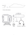
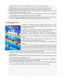
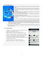
LCD Fish/Depth Finder
User Manual
ZHANGZHOU LILLIPUT ELECTRONIC TECHNOLOGY CO., LTD
ADDRESS: Zong Si Road, Lan Tian Economic Development Zone,
Zhangzhou, Fu Jian, 363005, China
TEL:0596-2109323、2109661
FAX:0596-2109611
http://www.lilliput.com.cn & http://www.gdsun.com
Email: [email protected]
Dear Customer:
:
Thank you for choosing Lilliput’s LCD fish finder. This product adopts
high-performance embedded computer hardware. It is designed for operations under
relatively harsh marine environments and featuring water prove, damp prove,
corruption protection, wide voltage range protection etc. The delicately optimized
design meets the requirements of all users in its applications to various conditions and
occasions. Lilliput aims to server our customer with its excellent quality and exquisite
manufacturing technology.
We encourage you to read this installation and operations carefully in order to get full
benefit from all the features and application of this product.
Notice:
:
Do not power on the equipment when the transducer is expose to the air. It might
cause the damage to the transducer.
Install the transducer according to the instruction. Do not bend, twist, pull or press
the cable of the transducer.
The extension cable needs to put inside the seal terminal box. The cable of the
transducer is not allowed to touch the surface of the boat.
Once the equipment’s power has been put into the “on” position do not switch the
computer’s power to the “off” position until the computer is fully booted.
Please make sure that the power voltage setting has been adjusted to the standard
voltage value of the location where the product is being used.
Before using this product, please first make sure that all external wires and power
adapters have been correctly connected. If you suspect any defects, please contact
your sales agent or factory personnel immediately.
Dust, humidity and dramatic temperature changes will affect the usage life of this
computer. Please keep the machine away from these hazards.
In cleaning the units do not use chemical detergents. Remove dust with a soft
cloth to ensure brightness.
Warnings:
:
High Voltage Circuit! Disassembly and repair of device should only be
performed by authorized service personal.
Power off the device from the plane immediately if there is water leaking into
the equipment. Continuous using the equipment might causes short circuit.
Please contact our service under those circumstances.
Do not attempt to modify or repair the original equipment. It may cause the
damage of the precious electronic components inside the device.
Power off the device from the plane immediately if there is fire or smoke
around. Continuous using the equipment might causes short circuit. Please
contact our service under those circumstances
1
Contents
1. Introduction...............................................................................................3
2. Specification...............................................................................................3
2-1. Functions..........................................................................................3
2-2. Parameter..........................................................................................4
3. Installation..................................................................................................4
3-1. Installation Summary........................................................................4
3-2. Whole Device Installation…….........................................................5
3-3. Main Device Installation...................................................................6
3-4. Transducer Installation..................................................................... 6
3-5. Device Cable Interfaces………........................................................8
4.
.Display Windows......................................................................................9
4-1. Title Screen.......................................................................................9
4-2. Sonar View…………………………….....................…………..... 9
4-3. Sonar Zoom View…………………….....................………….......11
4-4. Dual Sonar View……………………….....................………….....12
4-5. Big Digital View…….………………….....................…………... 13
4-6. Circular View…………………………….....................…….…… 14
4-7. System Status…………………………….....................….……… 15
5. Key Button Functions............................................................................... 15
6. The Menu System...................................................................................... 17
6-1. Main MENU………………………………......................………. 17
6-2. Detailed MENU…………………………..….....................…...... 18
6-3. Brightness adjustment……………………..….....................…...... 21
7. RARAMETER........................................................................................... 21
8. STANDARD ACCESSORIES……………………..……..…………...... 22
2
1. Introduction
Your fishing system user interface is easy to use. A combination of menu, keys,
different views, and situation-specific, customizable menus allows you to control the
color on display. Refer to the following illustration, and see functions, views and
menu systems for detail information.
1.4-WAY Cursor Control
2.MENU
3.VIEW
4.EXIT
5.POWER
6.Screen
2. Specification
2-1. Functions:
4.3” TFT LCD (resolution 480x320);
Composed of multi-color multi-level waveform is more delicate;
Manual adjustment range, the screen displays the waveform will not break;
Automatic underwater range and automatic identification without manual intervention;
pause screen brush map, move the cursor measurement of arbitrary target location;
Any manually set the display range up and down range;
User to adjust the screen split ratio;
Data recording and playback
High sensitivity gain and the gain in shallow water, clear bottom echo detection;
Multiple alarm modes: depth, voltage, fish, temperature;
Intelligent algorithm for more accurate identification of fish flesh, and a visual display;
Setting display: contour, windows, real-time window, color, background color, light;
A variety of protective measures: overvoltage, over current protection, reverse polarity
protection;
The whole machine adopts modular design, stability, reliability, default settings are not lost;
Silicone flexible and reliable touch of a button, the new soft keyboard functionality allows
simple operation of complex functions.
;
2-2. Parameters:
1. Display, 4.3” color LCD, (resolution 480X320)
2. Sonar colors: standard (4 colors, 32 levels), gray, reverse, inverse, green etc
3. Display Mode: Standard, bottom zoom, dual displays, large numbers, graphics, version
information, simulation
3
4. Auto Mode: Auto range, auto sensitivity
5. Display waveforms: Anyway to set, display the waveform will not be interrupted
6. Interference suppression: automatic suppression of interference signals with frequency
unwanted signal Interference suppression
7. Cursor operation: for any point on the screen depth measurement
8. Depth migration: ±5m
9. Alarm mode: fish alarm, depth alarm, battery alarm, temperature alarm
10. Resolution: 0.022 m
11. Screen split: vertical
12. Frequency: 83/200KHZ dual
13. Depth range: 0 to 100 meters
14. Chart speed: 1 to 10
15. Background colors: white, blue, black
16. Output power: 300W
17. Power supply DC 8.5V 24V
relative humidity below 95%
18. Working Environment 0 to 50
19. Storage Temperature 20-70
20. Degree of protection IP64
21. Weight: 960g
:
~
: ℃,
: ℃
:
3. Installation
3-1. Installation Summary
Avoid direct sunray,avoid impact shock.
The humidity and temperature condition of the install place should meet the
specifications.
The equipment should install in a well ventilated place, and keep away from the air pipe
and air vent.
Install the equipment in a sufficient room is recommended, therefore prepare enough
room for the cables and make it easy to carry out inspection and service.
Keep the equipment away from electromagnetic radiation device, such as motor and
generators.
4
3-2. Whole Device Installation
5
3-3 Main Device Installation
3-4.
.Transducer Installation:
Transducer is a precious front signal sensor. It must transport and install with care, no heavy
pressure, fall off or working in the air. Painting and parasite should keep away from the
surface of the transducer.
The mounting location is very important and will affect the measure accuracy of the
transducer directly. It is recommended to install it on the bilge where the surface is smooth
and flat. Keep the transducer far away from propeller or pipelines which generate turbulent
water. Keep the surface of the transducer horizontal, use guide plate to guarantee gentle water
flows if the bilge is not flat. Do not expose the transducer into the air under any
circumstances.
Mark and drill mounting holes:
6
1) Ensure that ship at the horizontal position, and the hull does not tilt.
2) Holding the transducer bracket template for the boat to mark the two mounting holes.
Center of two holes should be parallel to the surface. Ensure that the bottom of the
template and the distance between the lower edge of the beam is about 0 ~ 5 mm.
7
3-5. Device Cable Interfaces
8
4. Display Window
4-1. Title Screen
Turn on your device F403S by pressing the POWER key. The
title screen is display until the F403S begins operation. The
device will begin Normal or Simulator operation, depending
on your choice.
Press MENU to begin Simulator operation. The simulator data
is available under this mode; however the recording function
is unavailable under simulator mode. Otherwise it will enter
normal operating mode. In normal mode there, enter the last
visit of the view interface.
4-2. Sonar View
1. Sonar Color Bar: Color spectrum indicating low to high sonar
intensity returns, where red indicates high intensity and white
indicates low intensity, default value: standard.
2. Real Time Sonar Window: Display the real time sample data,
the display mode can be changed, default value: waveforms.
3. Water Surface Noise: The noise waveforms from Sonar returns.
4. Sonar Return: First sonar return, it indicates depth of the water
at present.
5. Second Sonar Return: When the sonar signal bounces between
the bottom and the surface of the water and back again. Use the
appearance of the second return to determine bottom hardness.
Hard bottoms will show a strong second return, while soft
bottoms will show a very weak one or none at all.
6. Third Sonar Return: When the sonar signal bounces between
the bottom and the surface of the water and back again.
7. Window 1: Water depth, can set depth alarm, default value: off.
8. Window 2: Input Voltage, can set low battery alarm, default value: off.
9. Window 3: The temperature display, the current location of underwater transducer
temperature, the current water temperature alarm can be set; set off according to user needs
or display, default value: off.
10. On the range: the range of display settings, you can manually set, default value: 0
11. The following range: Display settings under the scope, you can manually set, default value:
auto.
12. Depth contours: with three lines to the screen is divided into several equal portions, you can
also turn off the menu, default value: off
13. Background color: blue, white, black. Different background colors, font colors displayed
are not the same, default value: blue.
9
14. Sonar Color: Standard, green, gray, reversed. User-set according to personal habits, default
value: standard.
15. Underwater view: standard, white line. User-set according to personal habits, default value:
white lines.
16. Cursor measurements: the screen does not pop up in any menu, press the four arrow keys in
the "left" "right" measure. Measurement will pause the screen brush chart, four arrow keys
can be measured on the target. Measurement data is always displayed at the bottom left.
10
4-3. Sonar Zoom View
1. Window 1: bottom of the depth, you can set the alarm current
depth, degree, can be the rootAccording to the user needs to set off or
display, default value is: open.
2. Window 2: The current input voltage, current-voltage alarm can be
set; can display the user needs to set off or, by default is: Off.
3. Window 3: The temperature display, the current location of
underwater transducer temperature, the current water temperature
alarm can be set; set off according to user needs or display, default
value: off.
4. Water surface noise: often referred to as blind spots, is the
transducer emission arising from the waveforms.
5. Sonar Return: first sonar return, referring to the current bottom of
the depth. (The bottom number is based on the echo transducer power,
transmitting and receiving mode, and the depth of the underwater
geology, are not there are several echoes)
6. Second Sonar Return: When the sonar signals bounce back again
between the bottom and the bottom surface; use of the second return appearance to
determine the hardness of the bottom; hard bottom will show the first sonar return stronger
than the second one; and soft bottom will display the first sonar return weaker than the
second one.
7. Third Sonar Return: When sonar signals bounce back again between the bottom and the
bottom surface.
8. Amplified on the scope, the scope to take on the value of real-time changes, with the bottom
and change. Bottom with constant amplification factor is also a relationship.
9. Amplified under the scope, the scope to take on the value of real-time changes, with the
bottom and change. Bottom with constant amplification factor is also a relationship.
10. On the range: in the enlarged display screen on the range of values: 0, is fixed can not be
adjusted.
11. The following range: Display settings under the scope, you can manually set, default values
are: auto.
12. Screen separator: according to user habits can be set to low, medium or wide, default value:
in;
13. Magnification: Users can set their own needs X2, X4, X6, X8 magnification several routes.
11
X2
X4
X6
X8
4-4. Dual Sonar View
1. Window 1: Bottom of the depth,
you can set the alarm current depth, degree, according to
the user needs to set off or display, default value is: open.
2. Window 2: The current input voltage, current-voltage alarm can be set; can display the user
needs to set off or, by default is: Off.
3. Window 3: The temperature display, the current location of
underwater transducer temperature, the current water temperature
alarm can be set; set off according to user needs or display, default
value: off.
4. Water Surface Noise: often referred to as blind spots, is the
transducer emission arising from the waveforms.
5. 83KHz Sonar Return: first sonar return, referring to the current
bottom of the depth.
6. 83KHz Second Sonar Return: When the sonar signals bounce back
again between the bottom and the bottom surface; use of the second
return appearance to determine the hardness of the bottom; hard
bottom will show the first sonar return stronger than the second one;
and soft bottom will display the first sonar return weaker than the
second one.
7. 83KHz Third Sonar Return: When sonar signals bounce back again
between the bottom and the bottom surface.
8. 200KHz Sonar Return: first sonar return, referring to the current
bottom of the depth.
9. 200KHz Second Sonar Return: When the sonar signals bounce back again between the
bottom and the bottom surface; use of the second return appearance to determine the
hardness of the bottom; hard bottom will show the first sonar return stronger than the second
one; and soft bottom will display the first sonar return weaker than the second one.
10. 200KHz Third Sonar Return: When sonar signals bounce back again between the bottom
and the bottom surface.
11. Screen separator: separator screen dual screen when viewed with the sonar is not the same
12
magnification, this separator is fixed split screen. Size is not automatically set.
12. 83KHz frequency sonar: the instructions on the left area of 83KHz frequency sonar.
13. 200KHz frequency sonar: indicates that the right area to 83KHz frequency sonar.
14. Depth contours: with three lines to the screen is divided into several equal portions, you can
also turn off the menu, default value: off.
15. On the range: the range of display settings, you can manually set, default value: 0 (83KH z
is the simultaneous adjustment with no separation of 200KHz).
16. The following range: Display settings under the scope, you can manually set, default values
are: Auto (83KHz and 200KHz is the simultaneous adjustment is not separated).
4-5. Big Digital View
1. Window 1: The bottom of the depth, the depth can be set to the
current degree of alarm can be set according to user needs, or show
off, default value is: open.
2. Window 2: The current input voltage, current-voltage alarm can be
set; can display the user needs to set off or, by default is: Off.
3. Window 3: The temperature display, the current location of
underwater transducer temperature, the current water temperature
alarm can be set; set off according to user needs or display, default
value: off.
4. Water surface noise: often referred to as blind spots, is the
transducer emission arising from the waveform.
5. Sonar Return: first sonar return, referring to the current bottom of
the depth.
6. Second Sonar Return: When the sonar signals bounce back again
between the bottom and the bottom surface; use of the second return
appearance to determine the hardness of the bottom; hard bottom will
show the first sonar return stronger than the second one; and soft
bottom will display the first sonar return weaker than the second one.
7. Third Sonar Return: When sonar signals bounce back again between the bottom and the
bottom surface.
8. Depth contours: with three lines to the screen is divided into several equal portions, you can
also turn off the menu, default value: off
9. On the range: the range of display settings, you can manually set, default value: 0 (83KH z is
the simultaneous adjustment with no separation of 200KHz).
10. The following range: Display settings under the scope, you can manually set, default values
are: Auto (83KHz and 200KHz is the simultaneous adjustment is not separated).
13
4-6. Circular View
1. The first circle: underwater depth, you can set the alarm current
shades.
2. The second circle: scale, scope and under the scope of which can be
manually set, by default, the range of values: 0; next range is:
Automatic.
3. The third circle: water surface noise, underwater echo, the second
bottom echo, echo the bottom three:
a. the water surface noise: often refers to blind spots, the transducer
emission arising from the waveform.
b. Sonar Return: first sonar return, referring to the current bottom of
the depth.
c. Second Sonar Return: When the sonar signals bounce back again
between the bottom and the bottom surface; use of the second return
appearance to determine the hardness of the bottom; hard bottom will show the first
sonar return stronger than the second one; and soft bottom will display the first sonar
return weaker than the second one.
d. Third Sonar Return: When the sonar signals bounce back again between the bottom and
the bottom surface.
4-7. System Status
1. Version of S / N: number of current host body. Host factory
number, version number is fixed;
2. Model: Displays the current instrument model.
3. Software Version: current host software version number.
However, software upgrade, version number will change;
4. Voltage: The voltage is the voltage when the input value.
The input voltage changes with the current changes;
5. Total Time:This is the accumulate operation time from the
manufactory date till now.
6. PCB S/N: design date of hardware PCB board.
7. Indication message: Press “VIEW” to shift interfaces.
14
5. Key Button Functions
F403S user interface consists of a set of easy work with various on-screen views and menus to give
you flexibility and control over your fishing experience. Your control heads has the following keys:
1. 4-WAY Cursor Control
2. MENU
3. VIEW
4. EXIT
5. POWER
① 4-WAY Cursor Control
Four-in-one multi-function keys: composed of up / down, left / right arrow keys.
The four keys have different functions under different menus.
Up / Down key: up and down shift of the cursor in the menu.
Lift/Right key:
A. Selecting main items in the main menu.
B. In other sub-menu is to achieve choice, value addition and subtraction.
C. In the absence of pop-up menu screen, press the left or right button to
achieve the measurement function, press the EXIT or VIEW key to release
the current function.
② MENU
MENU key: to access the menu system. Boot Options menu - to view each option in the
menu. In the boot LOGO, if you press the MENU button then the host will start the
simulation system. In the rest of the system screen, press the MENU button will start the
first pop-up shortcut menu for the current interface; if not disappear in the current menu; press the
MENU button before the system will enter the main menu. All menu operated by the "Four-in-one
multi-function key" in the up / down or left / right. In the main menu, press the MENU key is to exit
the menu. Under normal circumstances: the up / down key is for selecting, the left / right key is for
setting.
③ VIEW
VIEW key: to achieve (Sonar View, Sonar Zoom View, Dual Screen View, Large
Number View, Circular View, System Status Windows) the windows switch. And the
data of windows will refresh when switch.
④ EXIT
EXIT key to exit in a single-level menu; to back to last menu in a multi-level menu;
to back to the front window when the menu window disappeared (opposite function
with VIEW ).
15
⑤ POWER
POWER key:
A. Press to pop-up "light" / "background color" shortcut menu, and then setting
through four-in-one multi-function key;
B. Press the power button of 2S device. The device is powered on when pressing the
POWER button. When the device is running, press the POWER key, the screen will
display the message "Power off Countdown" over the countdown, the host
immediately shut down and then release button; otherwise release after the operation is
disabled.
6. The Menu System
All multi-level or equivalent menu in the menu when pops up, to select through up / down key
of "Four-in-one multi-function key"; and then adjust through left / right key. Short press and
long-keep press for Left / Right adjustment. Short press to make step size adjustment effective
immediately; long-keep press to make value adjustment effective after release.
6-1. Main Menu:
1. Sensitivity :1-20 levels, short press to make step size
adjustment effective immediately; long-keep press to
make step size adjustment effective after release. This
feature is to adjust the level and width of sonar colors.
The default value is "10".
2. Upper Range:
A. “m” as unit: 0 to 397 levels, step size is 1, and the
minimum interval with lower range is 3m;
B. “feet” as unit: 0 to 1302 levels, step size is 1, and the
minimum interval with lower range is 10 feet;
C. “fathom” as unit: 0-216 levels, step size is 1, and the minimum interval with lower
range is 2 fathoms;
Short press to make step size adjustment effective immediately; long-keep press to make
step size adjustment effective after release. This feature shows location on the screen.
The depth of upper range is less than lower range, and different depth under different
units. The value of upper range is fixed to 0 when in the window of single tranducer
plus zoom, and default as 0 when in another window. Menu will pop-up through either
main menu or shortcut key.
3. Lower Range:
A. “m” as unit: 3 to 400 levels, step size is 1, and the minimum interval with lower
range is 3m;
B. “feet” as unit: 10 to 1312 levels, step size is 1, and the minimum interval with lower
range is 10 feet;
C. “fathom” as unit: 2-218 levels, step size is 1, and the minimum interval with lower
range is 2 fathoms;
Short press to make step size adjustment effective immediately; long-keep press to
make step size adjustment effective after release. This feature shows location on the
screen. The depth of upper range is less than lower range, and different depth value
16
under different units. Value default as 0, measuring range adjustment according to the
bottom of water. Menu will pop-up through either main menu or shortcut key.
4. Chart Speed :1-10 levels, short press to make step size adjustment effective
immediately; long-keep press to make step size adjustment effective after release. This
feature is to adjust the refreshing speed of sonar signal chart. The default value is "5".
5. Sonar Colors: standard (composed of 4 colors and 32 dominant hues), grayscale,
reversal and green; value default as "standard."
6-2 Detailed MENU
A. The alarm MENU
1. The upper depth alarm:
“m”: Off, 1-50 levels, step size is 1, and the minimum interval
with lower depth is 1m;
“feet”: Off, 1-100 levels, step size is 1, and the minimum
interval with lower depth is 2 feet;
“fathom”: Off, 1-50 levels, step size is 1, and the minimum
interval with lower depth is 1fathom;
Short press to make step size adjustment effective
immediately; long-keep press to make step size adjustment
effective after release. This feature shows location on the
screen. The upper depth alarm is less than lower depth alarm,
and different depth value under different units. Value default as "off".
2. The lower depth alarm:
“m”: Off, 3-400 levels, step size is 1, and the minimum interval with lower depth is 1m;
“feet”: Off, 10-1312 levels, step size is 1, and the minimum interval with lower depth is 2
feet;
“fathom”: Off, 3-218 levels, step size is 1, and the minimum interval with lower depth is
1fathom;
Short press to make step size adjustment effective immediately; long-keep press to make
step size adjustment effective after release. The upper depth alarm is less than lower depth
alarm, and different depth value under different units. Value default as "off".
3. Fish ID Alarm:
If you set the large fish alarm, alarm will make sound when large fish detected. Value
default as "off".
4.
Low voltage alarm: off, 8.5v-13v interval of 0.5v as a step size. After setting the alarm, if
the voltage is less than the current set value, it will be in red font and flashing on the screen.
17
Value default as "off"(and the voltage alarm is disable).
5. The temperature alarm: Off, 1 ℃ ~ 50 ℃ interval of 1 as a step size. After setting the
alarm, if the temperature is less than the current set value, it will be in red font and flashing
on the screen. Value default as "off".
6. Alarm types: low, medium and high. For alarm levels and alarm volumes, different volumes
in different levels when operating. Value default as "low".
B.
.Sonar
1. Bean Select: 200K, 83K, 200K/83K mixed;
default
value: 200K.
2. Surface Clutter: 1-20 levels, step size: 1, this feature is to
adjust the sonar return signal of transducer. The bigger
value, the stronger and wider of the sonar return; value
default as "10".
3. Fish ID: On / Off, the fish can be detected when the feature
is on, otherwise, only shows sonar information, not the fish
ID information. Value default as "Off".
4. Fish ID Sensitivity:1-10 levels, step size: 1, the higher
sensitivity, the more precise data for judge. to determine
the more detailed data. Value default as "5".
5. Real-time Window: Off, Standard, Wave; this feature shows
the real times of current sonar return. Users can set visual
graphical modes as their favors: Standard ( to distinguish
sonar intensity from color levels), Wave (to show width
and intensity of sonar return more visual with waveforms);
Value default as "ON".
6. Bottom View: Standard, White Line; Users can set visual
graphical modes as their favors . Value default as "White
Line".
7. Zoom Width: Low, Medium, High; this feature is available
in "Zoom View" mode, Users can set visual graphical modes as their favors . Value
default as "Medium".
8. 83KHz Sensitivity: -10 to +10 in step size of 1, adjust manually as the needs. Value default
as "0".
9. Depth Line: On / Off, value default as "On".
10. Noise filter: Low, Medium, High, value default as "Low".
11. Water type: Fresh, Salt. For the river and sea water, different quality with different
density.
12. Color bar: 4 colors and 32 kinds of dominant hues to distinguish different sonar signal
strength. Changed according to different sonar color.
18
C. Setup
1. Depth Units: Meter, Feet, Fathom; value default as "Meter".
2. Temperature Units: ℃, ℉; default as"℃".
3. Depth Offset: -5 to 5, is divided into 10 grades, step size is 1;
change as different ship’s drafts. Value default as "0".
4. Temperature Offset: -5 to 5, is divided into 10 grades, step size is
1; adjust manually when the detected and the actual temperature are
different. Value default as "0".
5. Reset: No, Yes.
6. Menu Timer: 5-30, divided into 25 grades; the pop-up menu will
exit automatically when the timer pass the current setting value;
value default as "15" seconds.
7. Select Readouts: window 1, window 2 and window 3, with: Off,
Voltage, Depth and Temperature for each one.
Default: Window 1: "Depth"; Window 2: "Off"; Window 3: "Off".
Setting through left and right key of the
"Four-in-one multi-function key". When the Depth is available, the
screen will flashing if no current bottom signals. When the
Voltage Alarm is on, the voltage display window will flash in red
characters if the current input voltage value is less than the voltage
alarm value.
8. Language: Chinese & English; default as “Chinese”.
D.View
1. Sonar View: On / Off, current screen shows only the
selected sonar return of "sonar frequency". Default as "On".
2. Sonar Zoom View: On / Off, current screen shows only the
selected sonar return of "sonar frequency". The screen is
divided into left and right parts, the parts size can be set
manually, as well as the zoom values. Default as "On".
3. Dual Sonar View: On / Off, dual windows for the screen
shows the sonar signal return of transducer. Default as
"On".
4. Big Digit View: On / Off, current screen shows only the
selected sonar return of "sonar frequency", to see depth data,
voltage and temperature of user’s location easily. Default as "On".
5. Circular Flas View: On / Off, current screen shows only the selected sonar return of "sonar
frequency" with the original status. Default as "On".
6.System Version: On / Off, current screen shows system information. Default as "Off".
19
6-3 Brightness Adjustment
1. Brightness: 0-10 levels, step size is 1, through the shortcut
key to pop-up shortcut menu, and then adjust the brightness
through the left and right keys of "Four-in-one
multi-function key". It’s effective immediately through
short press and long-keep press.
2. Back Ground Color: blue, white, black, users can set as their favors, value default as
"Blue".
20
7. PARAMETER
Panel
Input voltage
Frequency
Transmit power
Range
Accuracy
Interference suppression
Automatic range
Automatic sensitivity
The cursor measurement
Simulations show that
Fish identification
Display mode
Depth excursion
Shallow water alarm
Depth alarm
Low voltage alarm
Alarm type
Width Enlarge
Chart speed
Emission rate
Echo color
Operating Temperature
Safety Grade
Protection
Installation
Dimension(LWD)
Weight
4.3” TFT LCD (resolution480X320);
DC 9V~40V
83K/200K
300W
0-400m to 1 in steps of manually setting any
Full accuracy±1.0%
Yes
Yes
Yes
Yes
Yes
Yes
Sonar View, Sonar Zoom View, Double Sonar View, Big Digit
View, Circular View, Version Information, Simulation
±5m
0.4~30m
Upper depth
1~50m
Lower depth
2~400m
8.5~13V
Low, medium ,high
Narrow, medium and wide
1~10
Fastest 20T / s
32 grade 4 colors
-10℃~50℃
IP64
Over-voltage, over current, opposite polarity protection
Desktop, Hanging
185.6×154.7×61.9mm
600g (without transducer)
21
8. STANDARD ACCESSORIES
Number
Name
Quantity
Number
Name
Quantity
1
200K/83K Probe
1pcs
9
retreat line holder
1 pcs
2
Base
bracket
(KA4x22MM
screws
8 pcs
10
Jack import slot
1 pcs
3
Jack
import
screws(KB3×9)
slot
2 pcs
11
Device base
1 pcs
4
Line
holder
(KB2.3×6)
screws
2 pcs
12
Probe line holder
1 pcs
5
Probe rotation axis
1 pcs
13
Hull over the line of holes
1 pcs
6
Probe-like body mounting
bracket
1 pcs
14
Probe holder
1 pcs
7
Probe holder
1 pcs
15
User manual
1 pcs
8
Power cord
1 pcs
)
22