1
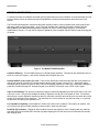
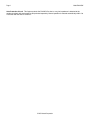
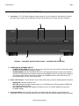
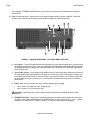
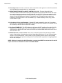
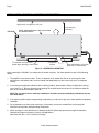
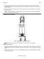
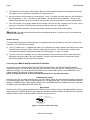
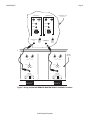
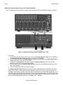
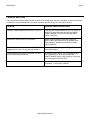
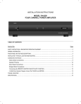
INSTALLATION INSTRUCTIONS MODEL PA4100X FOUR CHANNEL HI-POWER AMPLIFIER TABLE OF CONTENTS SectionTitle Page SAFETY INSTRUCTIONS - READ BEFORE OPERATING EQUIPMENT.........................................................................................................2 GENERAL INFORMATION .............................................................................................................................................................................3 PA4100X PANEL AND FEATURE DESCRIPTIONS ........................................................................................................................................5 INSTALLATION - PHYSICAL LOCATION AND MOUNTING ............................................................................................................................8 CONNECTING THE PA4100X.........................................................................................................................................................................9 Stereo Mode Connections ...................................................................................................................................... 9 Speaker Phasing.................................................................................................................................................. 10 Connecting the REMOTE MASTER ON/OFF MUTE CONTROL........................................................................... 10 A Multi-Zone System Diagram Using The PA4100X and MRC88 .......................................................................... 12 TROUBLE SHOOTING .................................................................................................................................................................................13 SPECIFICATIONS ........................................................................................................................................................................................14 Page 2 Model PA4100X SAFETY INSTRUCTIONS - READ BEFORE OPERATING EQUIPMENT CAUTION: TO REDUCE THE RISK OF ELECTRIC SHOCK, DO NOT REMOVE COVER (OR BACK) NO USER-SERVICEABLE PARTS INSIDE REFER SERVICING TO QUALIFIED SERVICE PERSONNEL WARNING: TO MINIMIZE THE CHANCE OF ELECTRICAL SHOCK, DO NOT OPERATE THIS PRODUCT WITHOUT HAVING SPEAKER CONNECTORS PLUGGED-IN The lightning flash with arrowhead symbol, within an equilateral triangle, is intended to alert the user to the presence of un-insulated “dangerous voltage” within the product’s enclosure that may be of sufficient magnitude to constitute a risk of electric shock to persons. The exclamation point within an equilateral triangle is intended to alert the user to the presence of important operating and maintenance (servicing) instructions in the literature accompanying the appliance. WARNING TO REDUCE THE RISK OF FIRE OR ELECTRIC SHOCK, DO NOT EXPOSE THIS APPLIANCE TO RAIN OR MOISTURE. This product was designed and manufactured to meet strict quality and safety standards. There are, however, some installation and operation precautions, which you should be particularly aware of. 1. 2. 3. 4. 5. 6. 7. 8. 9. 10. 11. 12. 13. 14. 15. 16. 17. 18. Read Instructions – All the safety and operating instructions should be read before the appliance is operated. Retain Instructions – The safety and operating instructions should be retained for future reference. Heed Warnings – All warnings on the appliance and in the operating instructions should be adhered to. Follow Instructions – All operating and use instructions should be followed. Water and Moisture – The appliance should not be used near water – for example, near a bathtub, washbowl, kitchen sink, laundry tub, in a wet basement, or near a swimming pool, etc. Carts and Stands – The appliance should be used only with a cart or stand that is recommended by the manufacturer. An appliance and cart combination should be moved with care. Quick stops, excessive force, and uneven surfaces may cause the appliance and cart combination to overturn. Wall or Ceiling Mounting – The appliance should be mounted to a wall or ceiling only as recommended by the manufacturer. Ventilation – The appliance should be situated so that its location or position does not interfere with its proper ventilation. For example, the appliance should not be situated on a bed, sofa, rug, or similar surface that may block the ventilation openings; or, placed in a built-in installation, such as a bookcase or cabinet that may impede the flow of air through the ventilation openings. Heat – The appliance should be situated away from heat sources such as radiators, heat registers, stoves, or other appliances (including amplifiers) that produce heat. Power Sources – The appliance should be connected to a power supply only of the type described in the operating instructions or as marked on the appliance. Grounding or Polarization – Precautions should be taken so that the grounding or polarization means of an appliance is not defeated. Power-Cord Protection – Power- supply cords should be routed so that they are not likely to be walked on or pinched by items placed upon or against them, paying particular attention to cords at plugs, convenience receptacles, and the point where they exit from the appliance. Cleaning – The appliance should be cleaned only as recommended by the manufacturer. Power Lines – An outdoor antenna should be located away from the power lines. Nonuse Periods – The power cord of the appliance should be unplugged from the outlet when left unused for a long period of time. Object and Liquid Entry – Care should be taken so that objects do not fall and liquids are not spilled into the enclosure through openings. Damage Requiring Service – The appliance should be serviced by qualified service personnel when: A. The Power-supply cord or the plug has been damaged; or B. Objects have fallen, or liquid has spilled into the appliance; or C. The appliance has been exposed to rain; or D. The appliance does not appear to operate normally or exhibits a marked change in performance; or E. The appliance has been dropped, or the enclosure damaged. Servicing – The user should not attempt to service the appliance beyond that described in the operating instructions. All other servicing should be referred to qualified service personnel. © 2003 Xantech Corporation Model PA4100X Page 3 GENERAL INFORMATION To enhance the ease of installation and obtain optimum performance from the PA4100X, we recommend that you first become familiar with all its features and special capabilities by studying the descriptions and instructions in this manual. The PA4100X was designed to meet the audio power amplifier needs of custom installed multi-zoned systems with high sonic quality and hi power output. It is a 4 Channel amplifier that is primarily intended to interface with the MRC88 Whole-house Audio Video Entertainment System for Zones 7 and 8 Preamp outputs or for Sub-Zone amplification of zones 1-6. It may also be used as a standalone 2-zone amplifier. Specific features and technology are as follows: Figure 1: The Model PA4100X Amplifier Cost/Size Efficiency. The PA4100X features four 100-watt power amplifiers. This permits each PA4100X to drive 2zones in a multi-zone system -- each with a 100-watt stereo amplifier per zone. Remote ON/OFF Control Jacks (C1 & C2). These 3.5mm Stereo Mini Jacks allow the PA4100X to be powered on and off and muted by a positive DC voltage ranging between 5 and 30 volts (11mA @ 12 V). Specifically, when interfaced with the Control Out jacks of zones 7 & 8 on the MRC88 (labeled CO1 and CO2), it permits the MRC88 to power the PA4100X ON and OFF automatically with zone ON/OFF commands or any 12VDC control signal. Input Level Flexibility. The input level (sensitivity range) is individually adjustable (per stereo pair) from a low of 0.2 volts up to 3 volts. This gives the installer the ability to adjust the overall gain of the system or zone. For instance, there may be a need to adjust the amplifier to deliver a controlled, maximum sound level into a zone when the volume control on the preamp is set to maximum. This would act as a volume limiter for any particular zone (i.e. to prevent the kids from over-driving wall speakers, etc.). Low Impedance Capability. Each amplifier is 4-Ohm safe under music conditions. This means, for instance, that you can drive two pairs of 8-Ohm speakers in stereo mode in each zone with ease. Peak/Clip LED Indication: Whenever either amplifier channel output starts to enter a clipping state, the channels front panel LED will illuminate RED. After the amp stops clipping the LED will return to its normal state 5-6 seconds after clipping stops. © 2003 Xantech Corporation Page 4 Model PA4100X Auto Protection Circuit. This feature protects the PA4100X if a short or very low impedance is detected at the speaker terminals with each amplifier pair protected separately. Normal operation is restored automatically within 3 to 4 seconds after the short is removed. © 2003 Xantech Corporation Model PA4100X Page 5 PA4100X PANEL AND FEATURE DESCRIPTIONS 1. Front Panel. 17" X 5.25” panel designed for shelf mounting. The unit measures 6” high with the Feet (Item #5). When rack mounting use an adequate rack shelf mount making sure to allow for proper ventilation. 3 4 2 1 5 FIGURE 2 – THE MODEL PA4100X FRONT PANEL – FEATURES AND FUNCTIONS 2. POWER ON/OFF/STANDBY SWITCH: POWER ON/OFF MODE: When the CI switch on the rear of the unit is set to OFF the front Power Switch will act as a standard ON/OFF (IN/OUT) control. STANDBY MODE: With the POWER SWITCH left in the IN position (and the CI switch set to ON) the 2 channels of PA4100X may be controlled remotely from the MRC88 via the CI1 and CI2 Control Inputs (or any Voltage Control Signal). When both channels enter STANDBY Mode the front LEDS will turn off leaving the amplifier in a low current sleep mode. 3. Status LED Indicators. These indicators, one for each channel pair, provide the following status information: GREEN LED: Indicates Amplifier is ON RED LED: Indicates associated channel output is in a CLIPPING state. LED will go back to GREEN 5-6 seconds after clipping subsides. ALL LED’s OFF: Indicates both amplifier channels are OFF or in STANBY MODE (see Item #4 for STANDBY MODE) 4. Illuminated LOGO: This is a backlit logo. When lit it indicates that the amplifier is powered ON. If the individual STATUS LED’s (Item #3) are OFF but the LOGO is ON, this indicates that both amplifier channels © 2003 Xantech Corporation Page 6 Model PA4100X are currently in STANDBY MODE. Whenever the LOGO is not illuminated, this indicates the amplifier is powered OFF. 5. Feet: Provides required ¾” spacing when unit is shelf mounted to allow for proper ventilation. These feet should not be removed. (see the section entitled INSTALLATION for further information) 14 6 7 8 6 12 11 9 11 13 9 10 FIGURE 3 – PA4100X REAR PANEL - FEATURES AND FUNCTIONS 6. Line Inputs. These RCA-type jacks are the audio inputs for each of the amplifier pairs. Connect them to the Preamp Output jacks of Zone 7 & 8 of the MRC88 (or other driving preamp output) with good quality RCA-type patch cables. Note that the inputs are marked LEFT-A-RIGHT, LEFT-B-RIGHT signifying the stereo channel pairs. 7. Input LEVEL Control. This screwdriver adjustable control (for each stereo pair) allows the input level for full rated power output to be adjusted over a range of 0.2 volts to 3 volts (24.3 dB range). Normally you would adjust the driving preamp to maximum volume, then set this control to the maximum volume that the client desires for a given zone or room. This prevents the system from being driven to unwanted power levels. 8. FUSE. When required, replace only with a fuse of the same type and rating: 120 V Version: 10.0 AMP 250 VAC, SLOW BLOW. 240 V Version: 5.0 A Time-Lag 250 VAC. CAUTION: Replacement with a fuse of higher rating will not protect the amplifier and will void the warranty. 9. SPEAKER Terminals. These plug-in 4-terminal screw type connectors permit speaker wire sizes up to 12 gauge. When making connections for the STEREO mode, be sure to observe the "+” and "–" polarity markings, just under the LEFT & RIGHT markings, for each wire pair going to the speakers. © 2003 Xantech Corporation Model PA4100X Page 7 10. Grounding Screw. Provides a means for chassis connection to earth ground or to other A/V products to aid in the reduction of system noise, etc., where needed. 11. REMOTE MASTER ON/OFF and MUTE CONTROL (CI1 & CI2). These two Stereo Mini Jack connections allow each individual channel pair of the PA4100X to be powered ON and OFF and muted by a control voltage ranging between 5 and 30 Volts DC (11mA @ 12 V). When connected to the C01 and C02 jacks from Zones 7 & 8 on the Xantech MRC88, this will allow remote Power ON/OFF control directly from the MRC88 System Controller. This allows the ‘A’ & ’B’ amplifier channel pairs to be individually controlled by Zones 7 & 8 of the MRC88. (Tip = ON/OFF Standby Control; Ring = Mute Control; Sleeve = gnd). 12. 3-Conductor AC Line Cord Receptacle. Standard IEC male receptacle for plug-in of a 3-conductor power line cord. Depending on the application, plug the line cord into a switched or un-switched 120V 60 Hz AC outlet (or 240 VAC 50 Hz on the 240 V version). 13. Rear Panel POWER LED. This LED indicates the AC power ON/OFF condition of the entire PA4100X, regardless of the Standby state. If the Front Power Switch is in the ON (IN) position and the unit is connected to an adequate AC Power source, this LED should be illuminated whether the front STATUS LED’s are ON or OFF. 14. REMOTE/LOCAL CI Control Switch: When set to the ON (UP) position, Remote Standby ON/OFF control of the amplifier will be determined by the Voltage state applied to the CI1 and CI2 control inputs (Item #11) (Front Power Switch – Item #2 must be in the IN position). When set to the OFF (DOWN) position, the amplifier will operate according to the Front Power Switch regardless of voltages applied to the CI1 and CI2 inputs. NOTE: With the CI switch in the ON (UP) position, a control signal MUST be used on the CI1 and CI2 inputs otherwise the PA4100X will remain in STANDBY MODE. © 2003 Xantech Corporation Page 8 Model PA4100X INSTALLATION - PHYSICAL LOCATION AND MOUNTING Upper shelf, component, wall, etc. PA4100X Keep perforations on top cover free of obstructions! To maximize air flow, route single large opening in lower shelf. Convection Airflow 2-inch spacing (minimum) Keep perforations on bottom plate free of obstructions. Figure 4 – HORIZONTAL MOUNTING When mounting the PA4100X, you should plan its location carefully. Pay close attention to each of the following factors: 1. The amplifier is convection cooled. That is, it depends on the natural free flow of air up through the slot perforations in the bottom plate, over the internal heat dissipating fins, then out the top cover, for adequate cooling. 2. If mounted in an equipment cabinet or other confining location, allow at least 2 inches of space above the top cover (see Fig. 4). Be sure there are large openings in the shelf below the unit and in the cabinet to allow the entry of cool air and the escape of warm air. NOTE: Do not remove feet in shelf-top installations and make sure top and bottom perforations are free from obstruction.. 3. If the cabinet contains other heat generating components, you will have to pay even closer attention to adequate ventilation. 4. Do not hesitate to use fans (quiet, boxer type), if necessary, to ensure a constant flow of air through the PA4100X's and the other heat generating components. 5. When mounting in a 19" (483mm) rack, adding a double RU (Rack Unit) above and a single RU below the PA4100X will improve convection in heavy use applications. [One Rack Unit size = 1-3/4" (44.5mm) in height]. © 2003 Xantech Corporation Model PA4100X Page 9 6. In multi-zone installations, you will have large bundles of wire and cable to accommodate audio, video and speaker connections. Be sure to allow enough strain relief for the leads and dress them in such a manner so as not to block airflow. 7. The PA4100X is designed for shelf mounting on flat horizontal surfaces. When mounting into a 19" rack, use an appropriate rack kit. NOTE: You should consider some sort of rear support for rack mounted units when used in mobile applications or when located in seismically-active areas. CONNECTING THE PA4100X PREAMP OUT 7 L R STATUS ZONE IR K E Y P A D PA435X Rear Panel RCA Type Patch Cords LEFT A RIGHT 1V LEVEL .2V 3V CI 1 SPEAKER DO NOT BRIDGE LEFT RIGHT + -- -- + Be sure speakers are connected with correct polarity as shown. + + Wall speakers, shelf speakers, etc. Left Right Figure 5 - PA4100X Stereo Mode Connections NOTE: When making connections to the PA4100X be sure the AC power cord is unplugged. Stereo Mode Connections 1. Using good quality RCA-type patch cables connect the L and R OUTPUT jacks of the MRC88 Pre Amp Output or other driving preamp to the LEFT and RIGHT input jacks on the PA4100X. Do this for each amplifier pair. Refer to Fig. 5. 2. Using good quality speaker wire, connect the individual speaker leads to the 4-terminal "SPEAKER" connectors on the PA4100X as shown. © 2003 Xantech Corporation Page 10 Model PA4100X 3. The PA4100X is 4-Ohm safe in Stereo Mode. Make sure the impedance presented to the speaker terminals by the speakers (or any combination of speakers) is 4-Ohms minimum. 5. Be sure to observe correct polarity by connecting the "+" and "–" terminal from each channel on the PA4100X to the corresponding "+" and "–" terminals on each speaker. This will ensure correct "phasing" - see Fig. 5 and Speaker Phasing below. Since the connectors are removable, you may unplug them for ease of lead assembly. 6. As a rule of thumb, use 18 gauge speaker wire for speaker runs up to 30' (9m), 16 gauge up to 70' (21m), and 14 gauge up to 150' (39m). The 4-terminal connectors accept wire sizes up to 12-gauge max. 7. Strip the insulation back about 1/4" (6mm) and twist the strands on each lead to prevent fraying. CAUTION: After lead ends are inserted and the screws tightened down, be sure there are no free strands that could cause shorting! Speaker Phasing To obtain stable imaging and full bass response, it is imperative that stereo speakers be connected "in phase" with each other. You can verify this as follows: a) If the "+" (positive) and "–" (negative) terminals on your speakers are correctly marked, and visible, and you have wired the system as shown in Figs. 5, then the system will be "in phase". No further action is required. Most manufacturers identify the positive terminal with a red binding post, a "+" sign, or a red dot. b) If you are unsure of the markings, you can verify the phasing. Using a mono sound source, such as AM radio, alternately reverse the leads to one of the speakers. Pick the connection that delivers a solid center image between the speakers as well as best bass response. Connecting the REMOTE MASTER ON/OFF MUTE CONTROL As mentioned under "PA4100X PANEL AND FEATURE DESCRIPTIONS", the REMOTE MASTER ON/OFF CONTROL inputs (CI1 & CI2) will allow the power to the PA4100X to be turned ON, OFF, and MUTED by remotely applied DC Voltages. Fig. 7 illustrates how a PA4100X can be switched ON and OFF via the MRC88 Zone 7 & 8 Control Outputs (CO1 and CO2) or other control source. NOTE: To enable this feature, be sure the CI Switch (Item #14) is in the ON (UP) position. On/Off Standby Control: Whenever a 5 to 30v dc voltage is applied to the TIP of the 3.5mm Stereo jack, the associated Amplifier channel will be activated (Powered ON). When the signal applied to the TIP approaches GND, it will put the associated Amplifier channel in STANDBY Mode. If both Amplifier channels are in STANDBY MODE the Amplifier will enter a “low power” STANDBY mode (Illuminated LOGO will remain ON). Mute Control: Whenever a 5 to 30v dc voltage is applied to the RING of the 3.5mm Stereo jack, the associated Amplifier channels signal output will be MUTED. When the signal applied to the RING approaches GND it will UN-MUTE the associated Amplifier channel and the audio signal will be returned to its previous level. Ring:12v DC = AMP MUTED Tip:12vDC = AMP ON Sleeve=GND Insulators 3.5mm Mini Plug (3-Conductor) Figure 6: CI Control Jack Pin Out Config © 2003 Xantech Corporation Model PA4100X Page 11 PREAMP OUT PREAMP OUT 7 8 L R L STATUS STATUS ZONE IR ZONE IR R K E Y P A D K E Y P A D REMOTE AMP CO1 MRC88 Rear Panel Zones 7 & 8 VIDEO OUT 7 REMOTE AMP CO1 VIDEO OUT 8 PA435X Rear Panel LEFT A LEFT RIGHT RIGHT 1V 1V LEVEL LEVEL .2V 3V .2V 3V CI 2 CI 1 SPEAKER SPEAKER DO NOT BRIDGE DO NOT BRIDGE LEFT B LEFT RIGHT RIGHT + -- -- + + -- -- + Figure 7: Using the PA4100X REMOTE MASTER ON/OFF CONTROL Terminals © 2003 Xantech Corporation Page 12 Model PA4100X A Multi-Zone System Diagram Using The PA4100X and MRC88 Fig. 8, following, shows the PA4100X in a typical multi-room system with a Xantech MRC88 eight-zone preamp. Use 3.5mm Stereo Mini Plug Cables RCA Type Patch Cords ZONE 7 ZONE 8 To Speakers in Rooms Figure 8: Interfacing the PA4100X with an MRC88 Zones 7 & 8 In this case: 1. Using good quality RCA Stereo Patch Cords, connect the Preamp Outputs of Zone 7 on the MRC88 to the Left and Right Audio Inputs labeled ‘A’ on the rear of the PA4100X. 2. Similar to step 1, connect the Preamp Outputs of Zone 8 on the MRC88 to the Left and Right Audio Inputs labeled ‘B’ on the rear of the PA4100X. 3. Using two 3.5mm Stereo Mini Plug cables, connect the Remote Amp CO1 jack on the rear of the MRC88 to the CI1 jack on the rear of the PA4100X 4. Similar to step 3, connect the Remote Amp CO2 jack on the rear of the MRC88 to the CI2 jack on the rear of the PA4100X. 5. Set the CI Switch (Item #14) to the ON (UP) position. The Remote Amp CO1 & CO2 (Remote Control Jack) from the MRC88 allows for individual Zone control directly from the Zone 7 & 8 keypads of the MRC88 system. When any one of the zones is turned on, the PA4100X is powered ON. Similarly, when either Zone is powered down, the associated amplifier pair on the PA4100X is put into STANDBY Mode. When both Zones (7 & 8) are powered down, the PA4100X will either go into STANDBY Mode on both amplifier pairs or will be POWERED OFF depending upon the position of the front panel POWER/STANDBY button (IN = STANDBY; OUT = ON/OFF). © 2003 Xantech Corporation Model PA4100X Page 13 TROUBLE SHOOTING If you encounter a problem, please review the items in the following list. Be sure, in addition, to check other system components, such as preamplifiers, CD players, speakers, speaker wiring, etc., that may be at fault. PROBLEM PROBABLE CAUSE AND SOLUTION Rear panel Power Indicator does not light – no sound. Check line cord for good contact in a live AC outlet. If REMOTE CI jacks are being used, be sure applied voltage is between +5V and +30V DC with proper polarity. See Fig. 6. Sound cuts in and out every 3 to 5 seconds. Speaker load impedance is less than 4-Ohms for Stereo mode or less than 8-Ohms for Bridged mode. Make changes in speakers as necessary to obtain higher impedance. PA4100X does not turn OFF when both REMOTE input voltages go to 0 Volts. The Logo stays illuminated. Be sure that the CI Switch (item 14, Fig. 3) is set to the CI ON (UP) position. PA4100X becomes very warm, shuts OFF, but does not come back ON automatically. Set POWER switch (item 2, Fig. 2) to MANUAL OFF (OUT) position for 15 seconds, then back ON. If REMOTE ON/OFF jack is used, unplug for 15 seconds, then re-plug with Front Power OFF. One or more front panel LED’s glow red. The amplifier has been driven into clipping and/or is overheating. Correct faulty condition. © 2003 Xantech Corporation Page 14 Model PA4100X SPECIFICATIONS Number of channels 4 Power Output 100 Watts at 8 Ohms Rated continuous power, each channel, all six channels simultaneously driven, 20 Hz to 20kHz, at rated THD Power Output 150 Watts at 8 Ohms & at 4 Ohms Short term continuous, each channel, 2 channels driven, 1 kHz, at rated THD Rated THD < 0.08% Damping Factor > 100 at 50 Hz, half rated power S/N Ratio > 100 dB A-weighted, shorted inputs, ref to rated power Frequency Response 12 Hz to 55 kHz at 1 Watt, ± 3dB Input Sensitivity at rated power, stereo mode, input gain Max: 0.2 V Default: 1.0 V Minimum: 3V Input Impedance Local Inputs: 22 kOhms Common Audio Buss Inputs: 70kOhms Power Source 120 VAC, 60 Hz TMRA 35° Celsius (95° F). If this temperature is exceeded, you will need to provide additional ventilation to ensure proper operation. 240 VAC, 50 Hz (European version) Power Consumption No signal: 30 Watts Standby Mode: 5 Watts 4 Channels at rated power: 1050 Watts Remote On/Off/Mute CI1 & CI2 Voltage/Current +5 V to +30 VDC (11mA at +12 VDC) Line Fuse Rating 120V version: 10A Slow Blow 250 VAC 240V version: 5A Time-Lag 250 VAC Dimensions 17” W x 6” H x 12.5” D (432 mm W x 152.4 mm H x 317.5 mm D) Weight 35.4 lbs (16.1 Kg) © 2003 Xantech Corporation Model PA4100X Page 15 © 2003 Xantech Corporation Page 16 Model PA4100X XANTECH CORPORATION 12950 Bradley Avenue, Sylmar CA 91342-3829 phone 818.362.0353 • fax 818.362.9506 www.xantech.com Part No. 08901195 Rev B 04-03-2003 © 2003 Xantech Corporation