1
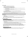
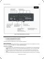
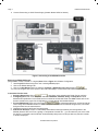
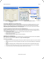
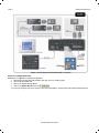
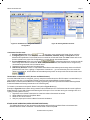
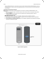
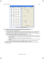
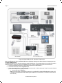
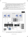
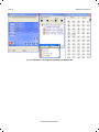
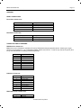
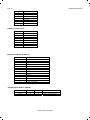
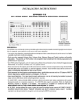
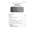
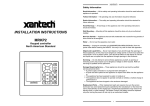
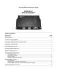
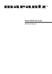
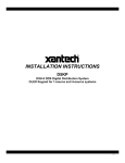
INSTALLATION INSTRUCTIONS
MODEL RS2321X8
RS232 1x8 Serial Router
TABLE OF CONTENTS
Table of contents ..................................................................................................................................1
Introduction ...........................................................................................................................................1
Features: ...........................................................................................................................................1
Specifications: ...................................................................................................................................2
Installation.............................................................................................................................................2
Power Wiring: ....................................................................................................................................2
Output Serial Wiring: .........................................................................................................................2
Configuration and Control: ....................................................................................................................3
MRC88 Integration: ...........................................................................................................................3
SmartPad LCD™ Integration:............................................................................................................5
Stand-Alone Operation (Infra-Red Port Switching):...........................................................................7
Appendix: ............................................................................................................................................13
Panel Connections: .........................................................................................................................13
Connector PinOut Diagrams:...........................................................................................................13
Baud Rate Selector Switch:.............................................................................................................14
Source Input Select Jumper: ...........................................................................................................14
INTRODUCTION
The RS2321X8 Serial Router allows individual control of up to 8 serially controlled devices from a single RS232 or RS422
Serial port. Use the RS2321X8 Router to Control banks of Plasma’s, HVAC, Lighting and any other serial controlled
devices with seamless switching between the 8 ports when used with the MRC88, MRAudio8x8 and SmartPad LCD™
control products. Each port, when selected, allows for bi-directional serial communication for local and remotely located
serial devices up to 4000ft away. The RS2321X8 serial router can also be controlled via IR for RS232/422 Port Switching
allowing it to be used with virtually any serial devices.
FEATURES:
• Four Addressable RS232 Output Ports
• Four Addressable RS422 Output Ports
• One RS232 Source Input Port
• One RS422 Source Input Port
• Green LED ‘selected port’ indicator for each of the eight Serial Ports
• Green ‘activity’ LED indicates IR RC68 Source Selection
• Red ‘Power’ indicator LED (indicates presence of 12VDC)
• Rotary Selector Switch for IR operation RC68 Code Group Setting
• Rotary Selector Switch for Baud Rate Selection
• Three pin jumper for Input Port Selection (RS232 or RS422)
• Easily mounts to flat wooden, plastic, or metal surfaces using the included screws.
Page 2
RS2321X8 Serial Router
SPECIFICATIONS:
• Power Input: 12VDC @150mA (2.1mm Coaxial Jack)
• RS232 Source Input Connection: Male DB9 Connector
• RS422 Source Input Connection: Female RJ45 Connector
• RS232 Output Connection: 4-Female DB9 Connectors
o Maximum Wire Distance from Router to Device: 100ft (distance may vary depending upon device and
wiring configuration)
• RS422 Output Connection: 4-Female RJ45 Connectors:
o Maximum Wire Distance from Router to Device: 4000ft (distance may vary depending upon device and
wiring configuration)
• IR Control Input Connection: 4-Screw Terminal (12VDC In/Out, GND, STATUS, IR INput)
• IR Control Default Group Code: 90
• Baud Rates Supported for Output Port Switching (Note: All Baud Rates Supported for RS232 Pass Thru): 300,
600, 1.2k, 2.4k,4.8k, 9.6k, 19.2k, 38.4k, 56kbps) Note: MRC88 uses 38.4kbps; SmartPad LCD™ uses 56kbps.
• Dimensions: 9.6” L x 3.0” W x 0.75” H (244mm L x 77mm W x 19mm H)
INSTALLATION
POWER WIRING:
1. Connect a 12VDC power supply (Xantech Model 781RG or 782-00 ) to the 2.1mm coaxial power input jack
(labeled 12VDC).
2. Plug the AC Adaptor into an un-switched AC Outlet.
Note: The Screw Terminal connection may also be used to hard-wire the power supply to the RS2321X8 Serial
Router. Use 18AWG to 24AWG 2-conductor wire connected to the 12VDC and GND screw terminals.
OUTPUT SERIAL WIRING:
Serial RS422 Output Wiring (Ports 1 thru 4):
Note: Use Xantech Model RS422232 (RS422 to RS232 Converter Module) to convert the RS422 output back to
standard RS232 Serial configuration directly at the Remote Serial Device to be controlled. RS422232 Module may be
placed up to 4000ft. from the RS2321X8 Router Port.
1. Connect one end of an RJ45 terminated CAT5 cable to the appropriate Serial Port (Labeled Port 1 thru 4) of the
RS2321X8 Router.
2. Connect the other end of this CAT5 cable to the connector labeled SERIAL on the RS422232 converter located at
the remote location within close proximity of the Serial device to be controlled.
3. Connect a Female DB9 terminated serial cable to the RS422232 connector labeled RS232.
4. Connect the other end of this cable to the Serial device being communicated to. (See Note1 below)
5. Connect a 781RG 12VDC power supply to the 2.1mm Coaxial Power jack on the RS422232 Converter.
Note1: Some Serial devices require the use of a ‘Null Modem’ cable or connector for proper communication. You will
need to consult the products instruction manual to see if this is required. Refer to Table 1A for Xantech Model
RS422232 Pin Out information.
Serial DB9 Output Wiring (Ports 5 thru 8):
1. Connect a Female DB9 terminated serial cable to the appropriate Serial Ports (labeled Port 5 thru 8) of the
RS2321X8 Serial Router.
2. Connect the other end of this cable to the Serial device being communicated to. (See Note1 above)
© 2005 Xantech Corporation
RS2321X8 Serial Router
Page 3
Figure 1: Basic RS2321X8 Router Connections
CONFIGURATION AND CONTROL:
The RS2321X8 Router can be controlled in three different configurations:
1. Connected to the MRC88 Multi-Zone Controller
2. Connected to the SmartPad LCD™ Controller
3. As a Standalone RS232 Router controlled via IR
The following sections will address each of these configurations individually.
MRC88 INTEGRATION:
When used with the MRC88, the RS2321X8 Router can seamlessly expand the Serial Control capabilities from 2 Serial
Ports to up to 16 Serial Ports. Note: Refer to Figure 2: MRC88 Integration.
CONNECTING TO THE MRC88:
1. Connect the Male end of a standard DB9 Serial cable (pinned 1:1) to the MRC88’s Com Port or Expanded Port
Note: Expanded Port requires the use of Xantech Model #05913665: Expansion 15 Pin to 9 Pin Serial Adapter
Cable.
2. Connect the Female end of the DB9 Serial Cable to the connector labeled RS232 IN on the RS232 Router.
3. Move the configuration jumper to the RS232 selection position located under the Configuration-Setup Access
Panel.
4. Make Sure the BAUD Rate setting (located under the Configuration-Setup Access Panel) is set to ‘7’ (38.4kbps)
© 2005 Xantech Corporation
Page 4
RS2321X8 Serial Router
5. Connect Power using a 12VDC Power Supply (Xantech Model 781RG or 782-00).
Figure 2: Connecting to the MRC88 Controller
ENABLING THE RS2321X8 ROUTER:
(Drag450MRC Version 3.0.build 77 or higher) Note: Refer to Figure 3 for Software Configuration.
1. Start DragMRC Software and open a new or existing MRC88 project.
2. Click on the RS232 Settings Tab.
3. Click on the Use Router check box under the Com Port or Expansion Port RS232 Sections.
You can now configure each of the 8 ports of the router individually to communicate with 8 different Serial devices.
CONFIGURING PORT SETTINGS:
1. Selecting Router Port: Click on
drop-down menu and select the Router Port to configure.
2. Configuring Port: Click on the drop-down menus for Baud Rate, Data Bits, Parity, and Stop Bit and set to
Manufactures specification for the Serial Device connected to the selected Router Port. Note: Please refer to the
devices manual for the proper Port Configurations or consult directly with the Manufacturer.
1. Process RS232 Input: Click on this check box
for bi-directional devices or any device that will
return strings to the MRC88’s Serial Port. Note: If this port is not selected, the MRC88 will ignore any commands
being sent back from the external device.
2. Repeat this process for all Router Ports being used.
3. Default Port Selection: If there is a main RS232 Serial Device that might randomly send strings back to the
MRC88 (Xantech XDT Dual Tuner, Lighting or Temperature Controller etc…) you can select the port on the router
this device is connected to and the Router will automatically always return to this port after any selection is made
to another output port.
© 2005 Xantech Corporation
RS2321X8 Serial Router
Page 5
Right-Click on
Command
Select Desired
Router Port
Figure 3a: MRC88 Dragon-IR Software
Configuration
Figure 3b: Routing RS232 Commands
PROGRAMMING THE MRC88 (ROUTING THE RS232 STRINGS):
Once the RS2321X8 Router is configured, you may now place commands onto the MRC88 Keypad buttons in normal
fashion (i.e. click on Button and click on corresponding RS232 Command under desired RS232 Command Palette).
Note: Please consult the MRC88 Manual for in-depth programming instruction (See Sections labeled Selecting RS232
Command Palettes and Placing Commands on the Virtual Keypad).
To Route the commands to the specific Router Ports (refer to Figure 3b above):
Example in Figure 3b shows a Macro being created under the MRC88 Keypad DVD button that will control 2 different
RS232 Devices (Turning ON a Plasma on Port 1 and selecting the DVD Input and also turning the room light OFF via a
Lighting Control system on Port 4).
1. Right-Click on the RS232 Command to be routed in the Macro Command List window
2. Select RS232 Port from the Drop Down Menu
3. Select the Port to be routed to
4. Verify the proper port is shown in Macro Command List Window
SMARTPAD LCD™ INTEGRATION:
When used with any of the SPLCD Models, the RS2321X8 Router can seamlessly expand the Serial Control capabilities
from 1 Serial Port to up to 8 Serial Ports. Note: Refer to Figure 4: SPLCD Integration.
CONNECTING TO THE SPLCD:
1. Connect one end of an RJ45 terminated CAT5 cable to the SPLCD’s Serial Port located on the rear of the SPLCD
unit.
2. Connect the other end of the RJ45 Terminated CAT5 Cable to the connector labeled RS422 IN on the RS2321X8
Router.
3. Move the configuration jumper to the RS422 selection position located under the Configuration-Setup Access
Panel.
4. Make Sure the BAUD Rate setting (located under the Configuration-Setup Access Panel) is set to ‘8’ (56kbps)
5. Connect Power using a 12VDC Power Supply (Xantech Model 781RG or 782-00).
© 2005 Xantech Corporation
Page 6
RS2321X8 Serial Router
Figure 4: Connecting to the SmartPad LCD™ Controller
ENABLING THE RS2321X8 ROUTER:
Note: Refer to Figure 5 for Software Configuration.
1. Start Dragon Drop-IR (SPLCD) Software and open a new or existing project.
2. Click on the OPTIONS Tab.
3. Click on the RS232 Settings Button.
4. Click on the Enable Router check box
.
You can now configure each of the 8 ports of the router individually to communicate with 8 different Serial devices.
© 2005 Xantech Corporation
RS2321X8 Serial Router
Page 7
Figure 5a: SmartPad LCD™ Dragon-IR Software
Configuration
Figure 5b: Routing RS232 Commands
CONFIGURING PORT SETTINGS:
1. Selecting Router Port: Click on
drop-down menu and select the Router Port to configure.
2. Configuring Port: Click on the drop-down menus for Baud Rate, Data Bits, Parity, and Stop Bit and set to
Manufactures specification for the Serial Device connected to the selected Router Port. Note: Please refer to the
devices manual for the proper Port Configurations or consult directly with the Manufacturer.
3. Process RS232 Input: Click on this check box
for bi-directional devices or any device that will
return strings to the SPLCD’s Serial Port. Note: If this port is not selected, the SmartPad LCD™ will ignore any
commands being sent back from the external device.
4. Repeat this process for all Router Ports being used.
5. Default Port Selection: If there is a main RS232 Serial Device that randomly sends strings back to the SPLCD
(Xantech XDT Dual Tuner, Lighting or Temperature Controller etc…) you can select the port on the router this
device is connected to, and the Router will automatically always return to this port after the last command is sent.
PROGRAMMING THE SMARTPAD LCD™ (ROUTING THE RS232 STRINGS):
Once the RS2321X8 Router is configured, you may now place commands onto the SPLCD buttons in normal fashion (i.e.
click on Button and click on corresponding RS232 Command under desired RS232 Command Palette).
Note: Please consult the SPLCD Manual for in-depth programming instruction (See Sections labeled Selecting RS232
Command Palettes and Placing Commands on the Virtual Keypad).
To Route the commands to the specific Router Ports (refer to Figure 5b above):
Example in Figure 5b shows a Macro being created under the SmartPad LCD™ DVD button that will control 2 different
RS232 Devices (Turning ON a Plasma and selecting the DVD Input on Port 1 and also turning the room light OFF via a
Lighting Control system on Port 4).
1. Right-Click on the RS232 Command to be routed in the Macro Command List window
2. Select RS232 Port from the Drop Down Menu
3. Select the Port to be routed to
4. Verify the proper port is shown in Macro Command List Window
STAND-ALONE OPERATION (INFRA-RED PORT SWITCHING):
The RS2321X8 Router can also be used as a stand-alone device allowing the Serial Ports to be selected with
Standard Xantech RC68+ Commands. The default RC68+ Code Group is 90.
© 2005 Xantech Corporation
Page 8
RS2321X8 Serial Router
Using the RS2321X8 Router as a stand-alone unit can be used to expand the Xantech Model IRS232A to control up
to 8 Serial Devices or anytime you want any single RS232 Device to communicate with up to 8 other Serial Devices
(or Vice-Versa).
CONFIGURING FOR STAND-ALONE OPERATION:
Note: The Xantech Model RC68+ Handheld Programmer is required for controlling the RS2321X8 Router in this
configuration.
1. Move the configuration jumper to the RS232 selection position located under the Configuration-Setup Access
Panel. See Figure 7.
2. Confirm the RC68+ Group Code dials are set to the desired Group Code setting (located in under the
Configuration-Setup Access Panel).
Note: Default Code Group is 90.
Note: Baud Rate setting is not used in this configuration. Setting is ignored in standalone operation.
3. Set the dials on the rear of the RC68+ Handheld Programmer to the same settings as noted in Step 2 above.
4. Place Overlay ‘C’ on the RC68+ Programmer.
5. Teach the 8 Router commands (buttons 1 through 8 on the RC68+ Programmer) to the IR Remote or IR Keypad
controller to be used with the system.
Figure 6: RC68+ Programmer
© 2005 Xantech Corporation
RS2321X8 Serial Router
Page 9
Figure 7: Selecting RC68+ Palette
APPLICATION EXAMPLE 1: USE WITH XANTECH MODEL IRS232A AND SMARTPAD3 PM110 IR KEYPAD.
1. Configure the RS2321X8 Router for Stand-Alone Operation as outlined above.
2. Connect all units as shown in Figure 8 below.
3. Program the IRS232A’s 36 Trigger banks for the proper RS232 Commands desired for up to 8 Different devices
(i.e. Triggers 1 thru 4 for a Projectors Input commands and Power ON/OFF; Triggers 5 thru 8 for an RS232
Controlled Thermostats Temperature UP/Down and HEAT/AC; Trigger Commands 9 thru 16 for a Music Servers
PLAY, STOP, PAUSE, NEXT SONG, PREV SONG, FF, REW, etc…)
4. Program the PM110 Source Buttons with the RS2321X8 Router RC68+ Commands.
a. In Dragon Drop-IR Software click on the PALETTE Menu and click on Select RC68+ Command Palette
from the drop-down menu (or simply press F5 on your keyboard). You should now see the Virtual RC68+
Command screen.
b. Select the OPTIONS tab as shown on the Virtual RC68+ Command screen.
c. Under XANTECH MODEL, make sure it is selected to either RT16-10 or RT8 (RT16-10 should be chosen
by default).
a. Change the CODE GROUP to 90 as shown in Figure 8 below. (Overlay should be selected to C)
5. Program the PM110 Function Buttons with the IRS232A RC68+ Trigger Commands
Note: Please refer to the Xantech IRS232A and PM110 Operational Manuals for full programming explanation for
each of these devices.
© 2005 Xantech Corporation
Page 10
RS2321X8 Serial Router
Figure 8: RS2321X8 Wired in IR ‘Standalone’ Application
APPLICATION EXAMPLE 2: USING THE RS2321X8 ROUTER IN REVERSE OPERATION: 8 SERIAL DEVICES COMMUNICATING WITH
TO A SINGLE RS232 DEVICE.
i.e. Multiple SmartPad LCD™ Panels controlling a single RS232 Device: This example will show how 8 SPLCD panels in
8 different rooms in a house or commercial establishment can control a single lighting system via it’s Serial Port.
1. Configure the RS2321X8 Router for Stand-Alone Operation as outlined above.
2. Connect all devices as shown in Figure 9 below.
3. Create a 2-command Macro under the SPLCD buttons that will: #1 Select the proper Router Port and #2 Send the
proper RS232 String to the Lighting Controller.
a. Click on the LIGHT ON Button.
Note: Here each button on the SPLCD controller for Light ON/OFF and DIM UP/DOWN will first send an IR
Command to the RS2321X8 Router selecting the Serial Port it is connected to. (i.e. SPLCD in Room #1 will
select Port #1)
© 2005 Xantech Corporation
RS2321X8 Serial Router
Page 11
b. In Dragon Drop-IR SPLCD (this example assumes you are using the Xantech SmartPad LCD Controller),
click on the PALETTE Menu and click on Select RC68+ Command Palette from the drop-down menu (or
simply press F5 on your keyboard). You should now see the Virtual RC68+ Command screen.
c. Select the OPTIONS tab as shown on the Virtual RC68+ Command screen.
d. Under XANTECH MODEL, make sure it is selected to either RT16-10 or RT8 (RT16-10 should be chosen
by default).
e. Change the CODE GROUP to 90 as shown in Figure 7 above. (Overlay should be selected to C)
f. Click on the proper Router button as shown on the RC68 (Button 1, 2, 3….8).
4. Open the RS232 Palette for Vantage and place the proper Macro commands under the IR Routing command in
step 8-f. See Figure 10.
Note: A 1 second delay might be needed in between the IR Router command and the RS232 command. If 1 Second
is too long try placing a ‘dummy’ IR command instead of the delay (this will be the equivalent of a .3sec delay.
Figure 9: Multiple SmartPad™ LCD panels Controlling a single RS232 Device
© 2005 Xantech Corporation
Page 12
RS2321X8 Serial Router
Fig. 10: SmartPad™ LCD Dragon Programming for Example #2
© 2005 Xantech Corporation
RS2321X8 Serial Router
Page 13
APPENDIX:
PANEL CONNECTIONS:
FRONT PANEL CONNECTORS:
Connectors (Input)
DB9 Male
RJ45
4-pin Weco
Power jack 2.1mm
Description
RS232 Input Source
RS422 Input Source
Xantech IR Bus connector
12.0 volts
REAR PANEL CONNECTORS:
Connectors (Output)
(4) DB9 Female
(4) RJ45
Description
RS232 Output Ports
RS422 Output Ports
CONNECTOR PINOUT DIAGRAMS:
DB9 MALE INPUT CONNECTOR:
Note: When used in Standalone operation (IR control), RS2321X8 behaves as standard switch – Meaning, the signal
placed on the pins will be a 1:1 pin configuration between INPUT and OUTPUT. Tx and Rx only need to be specific (Pins
2 & 3) when the MRC88 is controlling the switching directly.
Pin Number
1
2
3
4
5
6
7
8
9
Signal
Not used
Tx
Rx
DTR
Ground
DSR
Not used
Not used
Not Used
RJ45 INPUT CONNECTOR:
Pin Number
1
2
3
4
5
6
7
8
Signal
Receive Data +
Receive Data Transmit Data +
Request to Send Request to Send +
Transmit Data +
Clear to Send +
Clear to Send -
DB9 FEMALE OUTPUT CONNECTORS:
Pin Number
1
Signal
Not used
© 2005 Xantech Corporation
Page 14
RS2321X8 Serial Router
2
3
4
5
6
7
8
9
Tx
Rx
Not Used
Ground
Not Used
Not Used
Not Used
Not Used
RJ45 OUTPUT CONNECTORS:
Pin Number
1
2
3
4
5
6
7
8
Signal
Transmit Data +
Transmit Data Receive Data +
Receive Data -
BAUD RATE SELECTOR SWITCH:
Position
0
1
2
3
4
5
6
7
8
B
C
D
E
F
Selection
300 baud
600 baud
1200 baud
2400 baud
4800 baud
9600 baud
19200 baud
38400 baud
56000 baud
Unused
Unused
Unused
Unused
Factory Test Mode
SOURCE INPUT SELECT JUMPER:
Pin-1
ON
OFF
Pin-2
ON
ON
Pin-3
OFF
ON
Mode
RS232 is the input source.
RS422 is the input source
© 2005 Xantech Corporation
RS2321X8 Serial Router
Page 15
NOTES
© 2005 Xantech Corporation
Page 16
RS2321X8 Serial Router
XANTECH CORPORATION
13100 Telfair Avenue, Sylmar CA 91342-3829
phone 818.362.0353 • fax 818.362.9506
Part No. 08901020 Rev. A 04-07-05
© 2005 Xantech Corporation