1
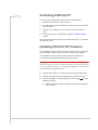
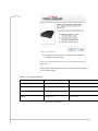
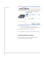
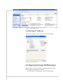
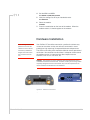
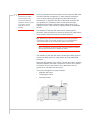
CoverTitle
PinPoint XT
Quick Start Guide
for Sprint
20070914
Rev 1.0A
Activating your PinPoint XT on Sprint
Network
• OMA-DM
• Hands Free
Activation (HFA)
• Activating PinPoint
XT
• Updating PinPoint
XT firmware
• Configuring through
ACEmanager
• Hardware
Installation
• Power
• Indicator Lights
This Quick Start guide provides step-by-step directions for activating
your PinPoint XT on Sprint’s network.
Tip: For additional configuration options, refer to the User Guide for your
PinPoint XT.
OMA-DM
PinPoint XT is an embedded router solution that supports Network
Initiated (NI) OMA-DM Device Configuration (DC) and PRL Updates
(PRL) on the Sprint network. The PinPoint XT firmware registers
notifications with the MC5727 radio module for OMA-DM NI alerts
and session state and processes them appropriately. The alert
response instructs the radio module to immediately process the NI
OMA-DM command. When the OMA-DM session state is IDLE,
PinPoint XT records the session type and session result code and
then re-establishes the data connection.
Hands Free Activation (HFA)
PinPoint XT automatically detects the radio module installed during
system startup. If the radio module is CDMA technology, PinPoint XT
will check the current provisioning state and if necessary execute
HFA. For devices that have previously been provisioned the HFA
routine is bypassed.
Rev 1.0A Mar.10
23
Activating PinPoint XT
To activate your PinPoint XT, follow the instructions below:
1. Connect the PinPoint XT with antennas.
2. Plug the power cable to the power connector on the back panel of
the PinPoint XT.
3. Connect your computer to the PinPoint XT with an ethernet
cable.
4. Observe the LEDs, as indicated in Chapter 4, Indicator Lights
section.
Wait approximately 30 seconds, to allow the PinPoint XT to initialize
and go over the air.
Updating PinPoint XT firmware
For installing the latest firmware version (.exe file), you can go to the
Sierra Wireless website: http://www.sierrawireless.com/support.
For the updater tool to execute, please install the USB drivers
available on the website before executing the .exe file.
Tip: Copy the USB Serial Driver.inf file to your desktop. Then power up the
PinPoint XT and connect USB. Install from specific location and point to this
.inf file. For detailed instructions on installing the USB drivers, please refer to
Universal Serial Bus Application Note.
1. Connect the PinPoint XT to your computer using anUSB cable.
2. Connect the power adapter and antennas to your PinPoint XT.
3. Install the PinPoint XT executable file by running the .exe file and
follow the prompts.
a. A Sierra Wireless firmware update welcome screen appears.
Click on Next.
Rev 1.0A Mar.10
24
Figure 0-1: Launch Screen
b. Choose the interface you want to program the modem
through and click on Next.
Note: You can use Boot interface only when a serial cable connection is
established.
The default private for Ethernet is also in a different subnet from the
other connection types.
Table 0-1: Factory Defaults
Interface
PinPoint XT
Connected Device
Ethernet Private default
192.168.13.31*
192.168.13.100
USB/NET
192.168.14.31
192.168.14.100
DUN
192.168.15.31
192.168.15.100
Wi-Fi*
192.168.17.31
192.168.17.100
*can be changed via ACEmanager
Rev 1.0A Mar.10
25
Figure 0-2: Configuration: Interface selection
c. The next screen will prompt you to reset the modem
manually. Click on Next after resetting the modem manually.
Installation begins and can take up to a few minutes.
Once the installation is complete, you will get a confirmation screen.
Verifying USB connection
Verify that your USB is connected as USB/net by checking the
Network Connections window in your computer.
Rev 1.0A Mar.10
26
Figure 0-3: Verify USB Connection
Confirming IP Address
Check the IP Address in your Local Area Connection window.
Figure 0-4: Confirm IP Address
Configuring through ACEmanager
ACEmanager is a free utility. Follow the steps below to connect to
ACEmanager for configuring the modem.
•
Rev 1.0A Mar.10
Ensure PinPoint XT connectivity to access ACEmanager.
27
•
Go to: http://192.168.13.31:9191 the first time you connect to
ACEmanager.
An alternate method to configure and activate your PinPoint XT is by
using AT commands sent directly to the modem with a terminal
application.
Caution: It is not possible to activate the PinPoint XT using either
ACEmanager or AceNet.
1. Set telnet timeout in to 20 minutes.
2. Save the telnet setting.
3. Enter the user name of your account (NAI). The user name is
usually expressed as an email address with phone number of the
account (example, [email protected]). This information
should be provided by your carrier. You may not need this step.
AT*NETUID=[NAI]
4. Enter the password of your account. This information should be
provided by your carrier. You may not need this step.
AT*NETPW=[password]
5. Verify ALEOS has established communication to the internal
hardware.
6. Enter the activation command appropriate for your type of
account. The SID and NID are optional and only required if your
account type uses them.
· If you have the same number for the MIN and MDN or MSID:
AT*PROVISION=MSL,MDN[,SID,NID]
· If you have the different numbers for the MIN and MDN or
MSID:
AT*PROVISION2=MSL,MDN,MIN/MSID[,SID,NID]
Using Direct Commands to the Internal
Hardware
Use only if the ALEOS method is unsuccessful.
Activating the Modem
1. Put modem into passthru mode to by-pass ALEOS. This will
allow direct communication with the wireless module for
programming. Entering passthru will take 10-15 seconds and
will return an ‘OK’ when it is complete.
AT\APASSTHRU
2. Verify you are in Passthru mode.
AT!STATUS
3. Unlock the module.
AT~NAMLCK=MSL
Rev 1.0A Mar.10
28
4. Set the MDN and MSID.
AT~NAMVAL=0,MDN,MSID,0,65535
5. Verify the settings are what you intended to enter.
AT~NAMVAL?0
6. Reset the module.
AT!RESET
7. Press the reset button on the front of the modem. When the
modem restarts, it should register on the network.
Hardware Installation
Note: During installation,
please be sure that the
cables are secure but do
not bear any additional
weight that could loosen
the connector from the
unit.
Your PinPoint XT should be mounted in a position that allows easy
access for the cables so they are not bent, constricted, in close
proximity to high amperage, or exposed to extreme temperatures.
The LEDs on the front panel should be visible for ease of operational
verification. You should ensure that there is adequate airflow around
the modem but that it is kept free from direct exposure to the
elements, such as sun, rain, dust, etc.
Caution: The PinPoint XT is in a hardened case and designed for use in
industrial and extreme environments. However, unless you are using cables
expressly designed for such environments, they can fail if exposed to the
same conditions the PinPoint XT can withstand.
Figure 0-5: PinPoint XT Connectors
Cellular
Rev 1.0A Mar.10
29
Note: This device is not
intended for use within
close proximity of the
human body. Antenna
installation should provide
for at least a 20 CM
separation from the
operator.
Antennas selected should not exceed a maximum gain of 5 dBi under
standard installation configuration. In more complex installations
(such as those requiring long lengths of cable and/or multiple
connections), it’s imperative that the installer follow maximum dBi
gain guidelines in accordance with the radio communications
regulations of the Federal Communications Commission (FCC),
Industry Canada, or your country’s regulatory body (if used outside
the US).
Your PinPoint XT will work with most cellular antennas with a
connector. Connect the primary antenna or primary RF cable directly
to the antenna connector on the back of the PinPoint XT.
Tip: When using a cable to an antenna placed away from the modem,
minimize the length of your cable. All gain from a more advantageous
antenna placement can be lost with a long cable to the modem.
Note: Your PinPoint XT does not have a second antenna for received
diversity. Received diversity is disabled by default.
Your PinPoint XT will work with most standard active GPS antennas.
Connect the GPS antenna or cable directly to the threaded SMA
connector.
Mount the GPS Antenna in the vehicle. The less the cable is wrapped
and bound together, the better it will perform. Place it on the roof, or
on the dash, or rear panel where it has a good view of the sky
(greater than a 90 angle view of the sky).
There are three options for antenna mounts:
•
Magnetic roof-mount
•
Through glass-mount
•
Permanent mount
Figure 0-6: GPS Antenna Placement for a Vehicle
Rev 1.0A Mar.10
30
Warning: Risk of electric shock: Only use the supply voltages listed in
this user guide.
Warning: When using AC to DC adapter the ambient temperature should
not exceed 40 0C.
Your PinPoint XT can be used with either DC or AC, with the
appropriate power adapter. DC cables and AC adapters are available
as optional accessories in addition to the one included with your
PinPoint XT.
The cable included with your PinPoint XT, is a DC cable with Standby
Ignition Sense which connects to the 20-pin I/O connector. Other
optional accessory cables include:
•
A DC power cable with a DB-9 female serial connector (P/N 120140-1021)
•
A DC power cable with I/Os (P/N 120-140-1022),
•
A fused DC power cable (P/N 120-140-1023),
•
A DC power cable with a battery-charger circuit
•
An auxiliary battery connector (P/N 120-140-1024)
•
A DC power cable with 4-pin adaptor (P/N 120-140-1025) which
connects to AC adaptor (P/N 120-100-1013).
The DC power cable positive lead should be connected to the battery
or power source positive terminal. The power cable negative lead
should be connected to the battery or power source negative
terminal.
The PinPoint XT has an internal polysilicon circuit breaker that opens
at 0.5 to 1.0 amps of current.
If you wish to use the Standby Ignition Sense (SISE) feature of your
PinPoint XT, the wire of the DC power cable should be used to
connect to your ignition. When SISE is enabled in the modem and the
ignition sense connector is wired to your vehicle, the ignition sense
will provide a link to the modem to enable it to enter a low-power,
standby mode when your vehicle is turned off and power up more
quickly when the ignition is started.
Warning: Explosion Hazard - Do not disconnect equipment unless power
has been switched off or the area is known to be non-hazardous.
Rev 1.0A Mar.10
31
Connecting to a Computer or other
Device
Figure 0-7: USB
Your PinPoint XT’s full-speed (12 Mbit) USB 2.0 port can be
connected directly to most computers or other devices using a
standard full-speed USB 2.0 cable. If the computer or device you are
connecting or the cable is not rated for full-speed, the modem will
communicate at a reduced speed to match. The PinPoint XT
functions as a device, not a host.
When it is connected to a computer, the USB port should be seen as
a COM port or Ethernet port after the applicable driver is installed.
The PinPoint XT has a standard mini-B connector.
Figure 0-8: I/O
Your PinPoint XT also has an I/O port with digital inputs, analog
inputs, and relay outputs which can be connected to external devices.
The I/O port can use an optional I/O harness available through Sierra
Wireless.
Indicator Lights
When solid, PinPoint XT indicates a successful connection. When
your PinPoint XT is connected to power and an antenna, there is a
specific pattern to the lights to indicate its operation mode.
Rev 1.0A Mar.10
32
Figure 0-9: PinPoint XT Indicator lights
•
Network - Indicates a successful connection to the cellular
network with an IP address given and a channel acquired.
RSSI LED Ranges
RSSI/Signal LED Status
Ranges of RSSI (dBm)
On Solid
Equal to or stronger than -69
Fast Blink
-70 to -79
Normal blink
-80 to -89
Slow Blink
-90 to -99
Extinguished
Equal to or weaker than -100
•
GPS - Indicates a GPS fix. When lit, the PinPoint XT has GPS
coordinates to report.
•
Power - Indicates the power adapter is connected and there is
power getting to the PinPoint XT.
Caution: If you reset the modem configuration using the reset button,
you may need to reactivate your PinPoint XT with Sprint.
Light Patterns
The LEDs on the front of the modem will respond in different patterns
to indicate modem states.
Rev 1.0A Mar.10
•
Normal - Each LED, mentioned above, is lit as applicable.
•
Start up - The LEDs will cycle from left to right.
•
PassThru mode - Network LED will blink.
•
Low Power - All LEDs will be off except the power LED which will
blink every 3 seconds.
•
Bad Firmware - The Network LED will blink.
•
Incorrect Firmware - The GPS LED will blink.
33