1
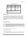
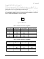
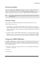
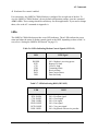
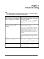
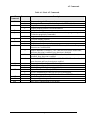
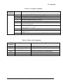
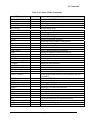
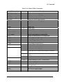
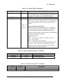
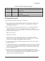
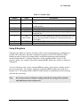
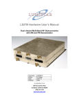
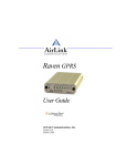
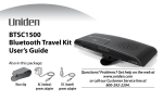
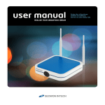
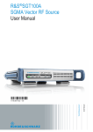
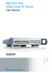
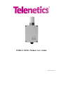
OMEGA CDMA Modem User’s Guide 0049-0709-002 Rev. A The products and programs described in this User’s Guide are licensed products of Telenetics Corporation. Telenetics Corporation does not warrant that the hardware will work properly in all environments and applications, and makes no warranty and representation, either implied or expressed, with respect to the quality, performance, merchantability, or fitness for a particular purpose. Information in this User’s Guide is subject to change without notice and does not represent a commitment on the part of Telenetics Corporation. Telenetics Corporation assumes no responsibility for any inaccuracies that may be contained in this User’s Guide. Telenetics Corporation makes no commitment to update or keep current the information in this User’s Guide, and reserves the right to make changes to this User’s Guide and/or product without notice. Important Notice Because of the nature of wireless communication, transmission and reception of data can never be guaranteed. Data may be delayed, corrupted (i.e., have errors), or be totally lost. Although significant delays or losses of data are rare when wireless devices such as the Telenetics OMEGA are used in a normal manner with a well-constructed network, the Telenetics OMEGA should not be used in situations where failure to transmit or receive data could result in damage of any kind to the user or any other party, including but not limited to personal injury, death, or loss of property. Telenetics Corporation accepts no responsibility for damages of any kind resulting from delays or errors in data transmitted or received using the Telenetics OMEGA, or for the failure of the Telenetics OMEGA to transmit or receive such data. Copyright 2003 Telenetics Corporation. 25111 Arctic Ocean Lake Forest, California 92630 Tel: (949) 455-4000 Fax: (949) 455-4010 Web site: www.telenetics.com FCC Radiation Exposure Statement The OMEGA CDMA product and its CDMA transceiver is approved for mobile operation only with respect to CFR 47 part 2.1091. FCC ID: N7NSB555 To ensure that the OMEGA meets the current FCC RF exposure guidelines, a separation distance of at least 20 cm (7.88") must be maintained between the OMEGA's antenna and the body of the user and any nearby persons at all time and in all applications and uses. Additionally, in mobile applications, maximum antenna gain must not exceed 9 dBi to comply with FCC regulation limiting both maximum RF output power and human exposure to RF radiation. FCC Part 15 EMI Statement This equipment has been tested and found to comply with limits for a Class A digital device, pursuant to Part 15 of the FCC rules. These limits are designed to provide reasonable protection against harmful interference in residential installations. This equipment generates, uses, and can radiate radio frequency energy, and if not installed and used in accordance with the instructions, may cause harmful interference to radio communications. However, there is no guarantee that interference will not occur in a particular installation. If this equipment does cause interference to radio or television equipment reception, which can be determined by turning the equipment off and on, the user is encouraged to try to correct the interference by one or more of the following measures: Reorient or relocate the receiving antenna Move the equipment away from the receiver Plug the equipment into an outlet on a circuit different from that to which the receiver is connected Consult the dealer or an experienced radio/television technician for additional suggestions You are cautioned that any change or modifications to the equipment not expressly approved by the party responsible for compliance could void your authority to operate such equipment. This device complies with Part 15 of the FCC Rules. Operation is subjected to the following two conditions 1) this device may not cause harmful interference and 2) this device must accept any interference received, including interference that may cause undesired operation. Page iii Contents CHAPTER 1 INTRODUCTION ..................................................................................................5 MODELS ............................................................................................................................................5 FEATURES .........................................................................................................................................6 OPTIONS............................................................................................................................................6 HARDWARE FEATURES .....................................................................................................................7 CHAPTER 2 INSTALLATION .................................................................................................10 INSTALLATION SUMMARY ...............................................................................................................10 UNPACKING YOUR HARDWARE ......................................................................................................11 ITEMS SUPPLIED BY THE USER ........................................................................................................11 OBTAINING CELLULAR TELEPHONE SERVICE .................................................................................11 ATTACHING MOUNTING FEET (STAND-ALONE OMEGA CDMA MODEM) .....................................12 INSTALLING THE OPTIONAL 8-PORT RS-232 MODULE ...................................................................12 POWER SUPPLY CONNECTIONS .......................................................................................................12 SETTING THE OMEGA DIP SWITCH ...............................................................................................13 DTR DIAL ENABLE .........................................................................................................................14 ATTACHING A DTE CABLE .............................................................................................................14 POWERING-UP THE MODEM ............................................................................................................16 CALL ANSWER TESTING .................................................................................................................16 CONFIGURING THE OMEGA CDMA MODEM ................................................................................16 LEDS ..............................................................................................................................................17 CHAPTER 3 TROUBLESHOOTING.......................................................................................18 APPENDIX A AT COMMANDS ...............................................................................................19 AT COMMAND LINE SYNTAX .........................................................................................................25 RESULT CODES ...............................................................................................................................26 USING S-REGISTERS .......................................................................................................................27 APPENDIX B INSTALLING THE 8-PORT RS-232 MODULE............................................29 VERIFYING PACKAGE CONTENTS ....................................................................................................29 INSTALLATION ................................................................................................................................29 EIGHT-PORT MODULE PORTS .........................................................................................................30 LIMITED PRODUCT WARRANTY ........................................................................................31 RETURN MERCHANDISE AUTHORIZATION (RMA) PROCEDURE ............................32 Page iv Chapter 1 Introduction he OMEGA OM-DIGX is an industrial-grade wireless modem that provides Code-Division Multiple Access (CDMA2000) 1xRTT connectivity for remote communications and data collection from the safety and comfort of the office. It is ideally suited to provide access to remote telemetry devices such as gas and electrical meters, corporate intranets from industrial vehicles and remote sites, and direct access to the Internet. T Note: The OMEGA Modem also is available as a Global System for Mobile Communications (GSM) cellular solution. For more information about the OMEGA GSM Modem, please contact Telenetics. Models The OMEGA CDMA Modem is available in four models: Type I stand-alone unit Type I stand-alone unit equipped with an optional 8-port RS-232 module Type II stand-alone unit Type II unit mounted on a Marwell socket adapter The Type I and Type II OMEGA CDMA Modems are functionally identical, differing only in size. Type I unit: 7” high x 7” wide x 3.3” deep (without antenna) Type II unit: 4.5” high x 3.5” wide x 3.15” deep (without antenna) Page 5 Introduction Features All OMEGA CDMA Modem models offer the following standard features: Dual-band support for both 800 MHz cellular and 1.9 GHz PCS bands. Adheres to CDMA authentication as specified in CDMA2000. Delivers data rates up to 153.6 Kbps (forward channel) and 76.8 Kbps (reverse channel). Adheres to the IS-95A protocol. Supports ITU-T V.34 data rates up to 14.4 Kbps. Supports MNP 5 and ITU-T V.42 data correction, and V.42bis data compression Supports the industry-standard AT command set. Provides an EIA RS-232/485 interface. Configurable anti-streaming (maximum online) time. Options All OMEGA CDMA Modem models also offer the following options: Marwell socket adapter. Low-profile antenna or external antenna. 8-port RS-232 module. DC low-voltage power supply. Page 6 Installation Hardware Features Figure 1-1 shows the hardware features of the Type I OMEGA CDMA Modem. Figure 1-2 on the next page shows the hardware features of the Type II OMEGA CDMA Modem. Figure 1-3 shows the Type II OMEGA CDMA Modem equipped with the Marwell socket adapter. Figure 1-1. Type I OMEGA CDMA Modem Page 7 Introduction Figure 1-2. Type II OMEGA CDMA Modem Page 8 Installation Figure 1-3. Type II OMEGA CDMA Modem with Marwell Socket Adapter Page 9 Chapter 2 Installation T his chapter describes how to install the OMEGA CDMA Modem. Installation Summary Installing the OMEGA CDMA Modem involves the following steps: 1. Unpack your OMEGA CDMA Modem. See page 11. 2. Obtain the additional items you need for installation. See page 11. 3. Obtain cellular telephone service. See page 11. 4. If you have the stand-alone OMEGA CDMA Modem, attach the mounting feet. See page 12. 5. Install the optional RS-232 module, if appropriate. See Appendix B. 6. Connect the OMEGA CDMA Modem to a power supply. See page 12. 7. Set the OMEGA CDMA Modem DIP switch. See page 12. 8. Use the pre-programmed Telephone/Mobile Identification numbers to have your RTU originate calls to its host via the RS-232 Data Terminal Ready (DTR) signal. See page 14. 9. Attach an RS-232 cable. See page 14. 10. Power-up the OMEGA CDMA Modem. See page 16. 11. Verify that the OMEGA CDMA Modem can answer incoming calls. See page 16. 12. View the OMEGA CDMA Modem’s current configuration. See page 16. Page 10 AT Commands Unpacking Your Hardware Remove the OMEGA CDMA Modem from its shipping carton and inspect it for damage. If your package contents are damaged or missing, please contact your place of purchase immediately. Your package should include: Either a stand-alone OMEGA CDMA Modem or one equipped with a Marwell socket adapter Mounting Feet Kit containing four mounting feet and screws (stand-alone unit only) This User’s Guide (optional) Items Supplied by the User To use the OMEGA CDMA Modem, you need the following additional items: A 90 VAC to 277 VAC power source (for AC models) or 3.3 VDC power source (for DC models) An RS-232 or RS-485 Data Terminal Equipment (DTE) cable, with an RJ-11 jack on one end for connecting to the OMEGA CDMA Modem if one is not provided (see page 15 for pin assignments) An external antenna if not purchased from Telenetics Adequate CDMA coverage (see “Obtaining Cellular Telephone Service,” below) Obtaining Cellular Telephone Service Before you install the OMEGA CDMA Modem, you must obtain cellular telephone service from your local service provider. As part of this process, your service provider will request the electronic serial number (ESN) of your OMEGA CDMA Modem’s cellular transceiver before a cellular telephone number can be provided. You can find the ESN on the inside front cover of the OMEGA CDMA Modem. You can also obtain the ESN by using the AT command AT+GSN (for more information about AT commands, see Appendix A). After you provide your local service provider with an ESN, the provider will give you a cellular telephone number (num) and the system ID (sid) that must be programmed into the OMEGA CDMA Modem. You can program the telephone number using the AT command AT~NAMVAL=nam, num, sid, nid <CR> (see Appendix A) or Telenetics can provide this service for you. Page 11 AT Commands IMPORTANT! Before you program the phone number and the system ID into the transceiver, use the default pass code to unlock the transceiver: AT~NAMLCK=000000, followed by AT~NAMVAL=nam, num, sid, nid <CR> After you obtain CDMA service, use the LEDs on the OMEGA CDMA Modem to verify the modem’s RSSI (see “LEDs” on page 17). Attaching Mounting Feet (stand-alone OMEGA CDMA Modem) The stand-alone OMEGA CDMA Modem comes with a Mounting Feet Kit that allows flexible mounting options for the OMEGA CDMA Modem. To use the mounting feet, align the hole on each mounting foot with the mounting hole on the OMEGA CDMA Modem and secure with a screw. Then use the hole on the other end of the mounting foot to secure the OMEGA to the appropriate surface. Installing the Optional 8-Port RS-232 Module If you purchased the optional 8-port RS-232 module, refer to Appendix B for instructions on installing the module in the OMEGA CDMA Modem. Power Supply Connections Note: If the Marwell socket adapter option has been purchased from Telenetics, skip this section. For OMEGA CDMA Modems equipped with an AC power connector, connect the OMEGA CDMA Modem to a single phase AC source in the range of 90 VAC to 277 VAC, at 50 or 60 Hz. Use a UL-listed and approved power cord, with a rating of 10 amps or above and a maximum wire size of 16 AWG. Figure 1-1 on page 7 and Figure 1-2 on page 8 show the location of the OMEGA CDMA Modem power connector. Table 2-1 lists the AC power connector reference information. For OMEGA CDMA Modems equipped with the DC low-voltage power supply option, a 3.3 VDC power source is necessary. Page 12 AT Commands Table 2-1. OMEGA CDMA Modem AC Power Supply Connector Power Cable Color Designation Modem Terminal Live Black 1 (left pin) Ground Green 2 (center pin) Neutral White 3 (right pin) Setting the OMEGA DIP Switch The OMEGA CDMA Modem provides an 8-position configuration DIP switch that selects various operating parameters. Review the switch settings in Table 2-2 and change any to suit your requirements. Table 2-2. OMEGA CDMA Modem Switch Settings Switch 1 Description ON OFF Baud Rate Selects the OMEGA CDMA Modem baud rate. Set these switches to match the speed of the attached DTE. See Table 2-3 for supported baud rates. 3 Parity Async character: 8-E-1 4 Sleep Mode (Reserved) 5 Interface Status or RSSI LEDs display RS-232 signals (default) LEDs display RSSI 6 Hardware Flow Control* Enabled Disabled (default) 7 DTR Dial Enabled Disabled (default) 8 RS-232/RS-485 Interface RS-485 RS-232 (default) 9 2/4 wire RS-485 2-W Half-duplex 4-W Full-duplex 10 Reserved Factory testing Set to OFF (default) 2 Async character: 8-N-1 Set to OFF (default) * If your RTU or meter only supports TXD and RXD signals, set switch 6 OFF to disable hardware flow control. In this mode, the OMEGA CDMA Modem ignores the Request-To-Send and other input control signals. Page 13 AT Commands Table 2-3. DTE Baud Rate Switch 1 Switch 2 Baud Rate (bps) OFF OFF ON ON OFF ON OFF ON 1200 2400 9600 (default) 19,200* * If you select 19,200 bps, set switch 6 ON to enable hardware flow control. DTR Dial Enable Using pre-programmed Telephone/Mobile Identification numbers, your RTU can originate calls to its host using the RS-232 Data Terminal Ready (DTR) signal. To enable this feature, set switch 7 to the ON position. Then use the AT*DTR command to assign the number that the OMEGA CDMA Modem is to dial (see Table A-4 on page 22). Then, when the RTU raises its DTR signal, the modem automatically dials the stored telephone number and attempts to establish a data connection. Once a remote connection is made, a drop in the DTR signal ends the connection. Attaching a DTE Cable Note: If the stand-alone OMEGA CDMA Modem is purchased from Telenetics, the RS-232 connection has already been made and this section can be skipped. However, if the Marwell socket adapter option is purchased from Telenetics or if the RS-485 interface is to be used, please read this section. The OMEGA CDMA Modem provides two DTE connectors: One for an RS-232 connection. One for an RS-485 connection. Both of these connectors are RJ-11 jacks. Only one of these connectors should be used at a time. Switch 8 on the OMEGA CDMA Modem controls which of these connectors is enabled (refer to Page 14 AT Commands “Setting the OMEGA DIP Switch” on page 13). To facilitate this connection, the OMEGA Marwell socket adapter comes with an RJ-11 extension cable. This cable lets you connect a DTE cable to the appropriate RJ-11 female jack, without having to insert the DTE cable into the modem enclosure. Figure 1-1 on page 7 shows the location of these connectors. Figure 2-1 shows a close-up of the RJ-11 jack, with pin 1 identified. Table 2-4 lists the pin assignments for the RS-232 connector. Table 2-5 lists the pin assignments for the RS-485 connector. PIN # 1 Figure 2-1. RJ-11 Jack Table 2-4. RS-232 Connector Pin Assignments RJ-11 Connector 1 Signal Name DCD Input /Output OUT DB-9 Pin Equivalent 1 2 RTS IN 7 3 TXD IN 3 4 CTS OUT 8 5 RXD OUT 2 6 SG NA 5 Table 2-5. RS-485 Connector Pin Assignments RJ-11 Connector 1 Signal Name Not Used Input /Output DB-9 Equivalent 2 TX+ OUT N/A 3 TX- OUT N/A 4 RX+ IN N/A 5 RX- IN N/A 6 Not Used Page 15 AT Commands Powering-up the Modem When power is applied to the OMEGA CDMA Modem, observe the modem LEDs. If switch 5 is set to ON, the Power, CTS, and DSR LEDs should all go ON after the modem performs its initialization for approximately 30 seconds. The RTS, DCD, TXD, and RXD LEDs go ON when a DTE is connected to the modem, a connection is established, and data is being transferred. Note: If the OMEGA CDMA Modem is not registered with the cellular network, the DSR LED will be OFF. Call Answer Testing After powering-on the OMEGA CDMA Modem, use the following procedure to test the modem’s ability to answer a call. 1. Use a telephone to call the OMEGA CDMA Modem. Listen to the call to verify that the OMEGA CDMA Modem answers the call with its answer tone and performs its handshaking sequence in an attempt to make a data connection. Hang up the handset of the telephone that originated the call. 2. Use another modem to call the OMEGA CDMA Modem. Verify that the OMEGA CDMA Modem answers the call, makes a data connection, and turns on the DCD LED. If the DCD LED does not go ON, make sure switch 5 is in the ON position to monitor RS-232 signals. Configuring the OMEGA CDMA Modem The OMEGA CDMA Modem is configured by issuing AT commands from a DTE connected to the OMEGA CDMA Modem’s serial port. Commands are sent using a terminal-emulation software program such as HyperTerminal. The terminal-emulation program must be configured to use the following settings: Baud rate: use the baud rate selected by Switches 1 and 2 on the OMEGA CDMA Modem (see Table 2-3 on page 14) Data bits: 8 Parity bit: none Page 16 AT Commands Hardware flow control: enabled For convenience, the OMEGA CDMA Modem is configured for use right out of the box. To view the OMEGA CDMA Modem’s factory default configuration settings, issue the command AT&V <CR>. These settings should be satisfactory for most applications. If you need to change them, refer to the AT commands in Appendix A. LEDs The OMEGA CDMA Modem provides seven LED indicators. These LEDs indicate the power status and either the status of modem control signals or the RSSI, depending on how switch 5 is set (refer to “Setting the OMEGA DIP Switch” on page 13). Table 2-6. LEDs Indicating Modem Control Signals (SW5 ON) LED POWER RTS CTS TXD RXD DCD DSR DTE Signal ON = Modem is receiving power Request To Send Clear To Send Transmitted Data Received Data Data Carrier Detect Data Set Ready Table 2-7. LEDs Indicating RSSI (SW5 OFF) LED RSSI RTS / RSSI6 CTS / RSSI5 TXD / RSSI4 RXD / RSSI3 DCD / RSSI2 DSR / RSSI1 ON = Excellent signal ON = Good signal ON = Fair signal ON = Poor signal ON = Very poor signal ON = Registered with service provider Page 17 AT Commands Chapter 3 Troubleshooting T his chapter describes troubleshooting procedures you can use in the unlikely event you encounter a problem with your OMEGA CDMA Modem. Problem Solution OMEGA is powered on and connected to DTE, but does not respond to commands. Be sure the modem and DTE are using the same port (baud rate) settings. Open the OMEGA and verify that the DSR LED is ON. If it is OFF, check the seating of the transceiver. When I initiate a call, the OMEGA responds immediately with NO CARRIER. Use a telephone to verify that the number you are dialing is valid and not busy. Use the AT command AT+CSQ to display the signal quality. If the first number is below 20, you may have poor reception from your current location. If the second number is 99, you are not getting the required wireless signal from your location. Use the RSSI DIP switch to display and check the received signal strength (see Table 2-2 on page 13). OMEGA does not answer incoming telephone calls automatically. Try the solution for initiating calls. Some data corruption is observed during data exchanges via a remote modem. Your selected data transmission rate needs flow control. Use Switch 6 to enable flow control (see Table 2-2 on page 13). Use the AT command AT&V to display most of the modem configurations. Verify that the value for the Register S0 is greater than 1. Page 18 Appendix A AT Commands o configure the OMEGA CDMA Modem, you issue AT commands from a Data Terminal Equipment (DTE) connected to the OMEGA CDMA Modem’s serial port. Commands are sent using a terminal-emulation software program such as HyperTerminal. The terminalemulation program must be configured to use the following settings: T Baud rate: use the baud rate selected by Switches 1 and 2 on the OMEGA CDMA Modem (see Table 2-3 on page 14) Data bits: 8 Parity bit: none Hardware flow control: enabled AT commands are organized into the following groups: Basic AT parameters see page 20. S-registers see page 21. Basic action commands see page 21. Cellular CDMA commands see page 22. QUALCOMM-proprietary commands see page 19 Telenetics-proprietary commands see page 24. The following tables summarize the AT commands that the OMEGA CDMA Modem supports. Page 19 AT Commands Table A-1. Basic AT Commands AT Command E I P Q Parameter Description 0 1 0 1 Do not echo typed AT commands. Echo typed AT commands back to the attached DTE (default). Display transceiver product version information. Display modem product version information. Use pulse dialing. Return result codes (required for modem transceiver programming and Telenetics-proprietary commands) Suppress result codes. Use tone dialing. (default) Display result codes as numbers. Display result codes as words. Enable additional result code CONNECT<rate>, dial tone and busy detection are both disabled. Enable additional CONNECT<rate> and NO DIALTONE result codes, dial tone detection is enabled, busy detection is disabled. Enable CONNECT<rate> and BUSY result codes, dial tone detection is disabled, busy detection is enabled. Enable CONNECT<rate>, BUSY, and NO DIALTONE result codes, dial tone detection and busy detection are enabled. Drop active call and reset to default configuration. Carrier Detect always ON. Carrier Detect follows data carrier (default). Ignore Data Terminal Ready (DTR). Go to Command Mode after ON-to-OFF DTR transition. Hang up and go to Command Mode after ON-to-OFF DTR transition. Set to factory default configurations. Dump configuration parameters. Save active configuration as user profile. 0 1 T V X 0 1 1 2 3 4 Z &C &D &F &V &W 0 0 1 0 1 2 Page 20 AT Commands Table A-2. S-register Commands AT Command S Parameter Description 0 3 4 5 6 7 Auto-answer (0-255; 0 disables auto-answer) Carriage Return character (default is 13 ASCII).. Line Feed character (default is 10 ASCII) Backspace character (default is 8 ASCII). Pause duration (2-10 seconds) before blind dialing (default is 2 seconds). Duration (1-255 seconds) to complete an end-to-end data connection (default is 50 seconds). Duration (0-255 seconds) to pause when a comma is encountered in a Dial string (default is 2 seconds). Carrier detect threshold, from 0-22 tenths of a second (default is 6). Number of tenths of a second (1-254) from carrier loss to disconnect (default is 14). DTMF tone duration and spacing, from 50-255 milliseconds (default is 95). 8 9 10 11 Table A-3. Basic Action Commands AT Command A D HO O A/ Parameter 0 to 9, *, #, A, B, C, D, T, P, W, @, !, $, ;, , Description Go off-hook, answer incoming call. Dial digits that follow the D command. Disconnect and return to Command Mode. Return to Online mode from Command Mode. Repeat last command Page 21 AT Commands Table A-4. Cellular CDMA Commands AT Command *? *CLIENT= *CLIENT? *D= [string] *D? *DIP [xxx.xxx.xxx.xxx] *DTR Parameter 0 1 1 0 *DTR? *F *H *HIP *I *IPR= [baud] *IPR? *LIP= [xxx.xxx.xxx.xxx] *LIP? *LOOP *LPASS= [string] * LPASS? *LUSER= [string] *LUSER? *MAC= [string] *MAC? *MRU= [number] *MRU? *NETSTAT *PING= [xxx.xxx.xxx.xxx] *PORT= [number] *PORT? *PPP= *PPP? *R= [secs] *R? *RESET *RIP= [xxx.xxx.xxx.xxx] *RIP? 1 0 Description Display list of OMEGA commands. Disable Client mode. Enable Client mode. Display Client mode activation. Set auto dialup string. Display auto dial-up string. Connect to given IP address. Enable DTR dialing. Disable DTR dialing. Display DTR dialing activation. Restore the default OMEGA configuration. Hang up the modem connection. Hang up the active IP connection. Display the controller firmware version. Set the controller-transceiver baud rate. Display the controller-transceiver baud rate. Set the local IP address. Display the local IP address. Enter loopback mode. Set the local password. Display the local password. Set the local username. Display the local username. Set the controller MAC address or telephone number. Display the controller MAC address or telephone number. Set the Point-to-Point Protocol (PPP) Maximum Receive Unit (MRU). Display the PPP MRU. Display network statistics. Ping the specified IP address. Set the TCP and UDP listen port. Display the TCP and UDP listen port. Enable PPP. Disable PPP. Display PPP activation. Set the transceiver re-registration interval. Display the transceiver re-registration interval. Restart the system. Set the remote IP address. Display the remote IP address. Page 22 AT Commands Table A-4. Cellular CDMA Commands AT Command *RPASS= [string] *RPASS? *RSSI *RUSER= [string] *RUSER? *SIP= [xxx.xxx.xxx.xxx] *SIP? *T= [secs] *T? *UDP= *UDP? *VM= [config] *VM? *VT= [config] *VT? *W *WTCP= *WTCP? +CAD? +CRC=<value> +CRM=<value> Parameter 1 0 1 0 0 1 0 1 2 3 +CQD=<value> +CMIP? +CBIP? +CSS? +CSQ? !RSSI? !STATUS 4 0 1-255 Description Set the remote user login password. Display the remote user login password. Display the Received Signal Strength. Set the remote login username. Display the remote login username. Set the remote server IP address. Display the remote server IP address. Set the maximum connection time. Display the maximum connection time. Enable UDP. Disable UDP. Display UDP activation. Set the default modem AT configuration. Display the default modem AT configuration. Set the default transceiver configuration. Display the default transceiver configuration. Save the active configuration. Enable TCP waiting for ACK. Disable TCP waiting for ACK. Display the TCP waiting activation. Query analog or digital service. Disable cellular result codes (default). Enable cellular result codes. Asynchronous data (default). Packet data service, relay layer transceiver interface. Packet data service, network layer transceiver interface PPP. Packet data service, network layer transceiver interface SLIP. STU-III service Ignored Release call after 5x<value> seconds elapse. Mobile station IP address Base station IP address Identifies if mobile station is registered with A- or B-band, or not registered. Query Received Signal Quality Received line signal strength Status of the OMEGA CDMA modem Page 23 AT Commands Table A-4. Cellular CDMA Commands AT Command ~NAMLCK Parameter ~NAMVAL?0 ~NAMVAL= Description Stores the pass-code number provided by the service provider when service is activated. Returns OK if number is acceptable. The default is AT~NAMLCK=000000. Query the stored account information in the transceiver Sets the active account index. The OMEGA CDMA Modem supports two accounts. Using only the <nam> parameter (0 or 1) sets that account as the active account used by the modem. <nam>,<nu m>, Write Account Activation Data <sid>,<nid This form requires the optional parameters. The modem > first compares the pass-code stored using ~NAMLCK. If the pass-code fails to match, an ERROR result code is returned. If the OK result code is returned, the NAM profile account was activated successfully. Parameters values are: NAM: < 0 or 1 > NUM: < 10 digit phone number, including area code > SID: < up to 6 digits > NID: < leave blank or up to 6 digits > The service provider will tell you which numbers to enter for <num>, <sid>. And <nid>. The choice of account (NAM) is up to you. After writing the values, reset the modem to have the values take effect. Table A-5. QUALCOMM-Proprietary Commands AT Command $QCQNC= $QCVAD= Parameter <value> <value> Description Packet call behavior Pre-arrangement setting Table A-6. Telenetics-Proprietary Commands AT Command *R= *R? Parameter <value> Description Set period, in seconds, for re-registration. Show re-registration period. Page 24 AT Commands Table A-6. Telenetics-Proprietary Commands AT Command *S= Parameter <value> *S? *T= <value> *T? Description Set number of seconds to wait after modem inactivity before going to sleep. Show time to wait before going to sleep. Set maximum connection time, in seconds (default is 0=disabled). Show current timeout setting. AT Command Line Syntax Observe the following guidelines when typing AT commands: Each command line starts with the characters AT or at. These characters cannot be mixed (for example At or aT). The characters AT preface every command line, except those containing the A/ command. Some commands require a numeric parameter such as 0, 1, or 2 to completely define the command. Omitting a parameter from a command that requires one is equivalent to specifying a parameter of 0. For example, the Qn command determines whether the OMEGA CDMA Modem sends result codes. Q0 activates result codes. Q1 suppresses result codes. Omitting a parameter from a command that requires one is equivalent to specifying a parameter of 0. If you type the Qn command without specifying either 0 or 1, for example, it's equivalent to sending the command Q0 and enables result codes. A command line ends with an ASCII CR (carriage return) character. This can be changed through the S3 register. A command line can contain up to 128 command characters. Basic and S-register commands can follow each other without any separating delimiters. Extended format commands, which start with +or $, must be delimited with a semicolon (;). The semicolon is not required after the last command on the line. By default, when you send a command line to the OMEGA CDMA Modem, the Modem sends a result code such as OK. This is because the default ATQ0 command is in effect. You can disable result codes using the ATQ1 command or change from word result codes to numeric result codes using the ATV0 command. Page 25 AT Commands The OMEGA CDMA Modem stores the last-executed command line in memory until it executes a new one. To re-execute the last command line you sent, type A/ without typing AT or at in front of it or pressing <cr> after typing it. If the modem is reset or loses power, the last-executed command is lost from memory. This renders the A/ command useless until the modem executes a command line. Result Codes By default, when you send a command line to the OMEGA CDMA Modem, the OMEGA CDMA Modem sends a result code such as OK. This is because the default Q0 command is in effect. To disable result codes, issue the Q1 command. To reactivate result codes, issue the Q0 command. When result codes are enabled (Q0 is in effect), you can select the result code sets from which the result codes are fetched. The OMEGA CDMA Modem provides six result code sets, designated X1 through X4. Table A-7 on page 27 lists the result codes contained in each result code set. Result codes can appear as English words or numbers, depending on the Vn command in effect. The V1 command enables word result codes. Word result codes are followed by a carriage return and line feed. The V0 command enables numeric responses. Numeric result codes are followed by a carriage return only. Numeric result codes are useful if the OMEGA CDMA Modem is operating under an application that either cannot handle character strings or handles them inefficiently. Page 26 AT Commands Table A-7. Result Codes Number 0 Word OK 1 CONNECT 2 3 4 RING NO CARRIER ERROR 6 NO DIALTONE 7 8 BUSY NOANSWER Description The OMEGA CDMA Modem executed a command line without errors. The OMEGA CDMA Modem has made a data connection with another modem. The OMEGA CDMA Modem has detected an incoming call. A carrier from the remote modem was lost or was not present. The OMEGA CDMA Modem found an error in your typed command line. The OMEGA CDMA Modem did not detect a dial tone before the timeout period specified by Register S7 elapsed (default time is 50 seconds). The OMEGA CDMA Modem has detected a busy signal. Five seconds of silence were not detected after a ring. Using S-Registers S-Registers are addresses of places in memory where various timing parameters, redefinitions of selected ASCII characters, and other configuration settings are stored. The OMEGA CDMA Modem provides S registers for setting modem configuration parameters and establishing modem default behavior. To display S-Registers, use the command ATSr?, where r is the register’s number. For example, issuing the command ATS0? displays the contents or setting for S-Register 0. To set an S-Register value, use the command ATSr=n, where r is the register’s number and n is the new register value. For example: issuing the command ATS0=2 changes the setting for SRegister 0 to 2. This setting tells the OMEGA CDMA Modem to automatically answer incoming calls after the second ring. Note: If you do not write an S-Register setting with &W, the setting will be retained only until the next reset or power off. Page 27 Appendix B Installing the 8-port RS-232 Module he 8-port RS-232 module allows up to eight endpoint devices (such as meters, relays, and controllers) to connect to a single OMEGA CDMA Modem. This appendix describes how to install the 8-port RS-232 module. If you do not have this optional module, you can skip this appendix. T Verifying Package Contents The 8-port RS-232 module package contains the following items: One OMEGA 8-Port RS-232 Module Four metal standoffs Four screws If any of these items are missing or damaged, please contact Telenetics immediately. Installation The 8-port RS-232 module is designed for simple installation in the field. 1. Set the OMEGA Power Battery switch to the OFF position. 2. Open the OMEGA CDMA Modem cabinet. 3. Insert a metal standoff into each of the four threaded inserts on the OMEGA baseboard. 4. Hold the module above the J32 connector on the OMEGA baseboard, so its gold pins are facing down toward the connector. 5. Gently insert the gold pins into the connector. Align the holes on the module with the holes on the threaded inserts. 6. Use the four supplied screws to secure the module to the standoffs. Page 29 Installing the 8-port RS-232 Module 7. Close the OMEGA CDMA Modem cabinet. 8. When the OMEGA is configured with a default port and receives a dial string with no port number, it waits 10 seconds and then automatically routes the call to the default port specified by the command: \PD=<port number> <CR> To disable a default port, use a laptop computer connected to the OMEGA’s DB-9 connector to send the following command from a terminal-emulation program: \PD=0 <CR> Eight-Port Module Ports When the 8-port RS-232 module is installed, port 1 is the leftmost port and port 8 is the rightmost port when you face the module. Page 30 Limited Product Warranty Telenetics warrants that the Product sold will be free from defects in material and workmanship and perform to Telenetics' applicable published specifications for a period of 18 months from the date of delivery to Customer or 12 months from placement into service, whichever occurs first. The liability of Telenetics hereunder shall be limited to replacing or repairing, at its option, any defective Products which are returned F.O.B., Telenetics' facility, Lake Forest, California (or, at Telenetics' option refunding the purchase price of such products). In no case are Products to be returned without first obtaining permission and a customer return order number from Telenetics. In no event shall Telenetics be liable for any consequential or incidental damages. Products which have been subject to abuse, misuse, accident, alteration, neglect, unauthorized repair or installation are not covered by the warranty. Telenetics shall make the final determination as to the existence and cause of any alleged defect. No liability is assumed for expendable items such as lamps and fuses. No warranty is made with respect to custom products or Products produced to Customer's specifications except as specifically stated in writing by Telenetics in the agreement for such custom products. This warranty is the only warranty made by Telenetics with respect to the goods delivered hereunder, and may be modified or amended only by a written instrument signed by a duly authorized officer or Telenetics and accepted by Customer. This warranty and limitation extends to customer and to users of the product and is in lieu of all warranties with respect to the product whether express, implied, or statutory, including without limitation the implied warranties of merchantability and fitness for a particular purpose. Page 31 Return Merchandise Authorization (RMA) Procedure Before returning any Telenetics product, an RMA number must be obtained. Before asking for an RMA number, ascertain that the product was purchased from Telenetics. If you bought the product from a Distributor or Systems Integrator, the product should be returned to that vendor. The most convenient method to obtain an RMA number for a product purchased from Telenetics is to send an email to [email protected]. Information required must include Your Company Name, address, the actual address that we would use to return the product to you. Please include any Mail Stop or specific delivery information. The City, State, and zip code are all required. Your phone and FAX numbers. Your email address. If the above information is on your letterhead, that format is acceptable. For each item you wish to return: List the product model number, usually found on the serial number tag, the serial number for each item you wish to return, a description of the problem you are encountering, and the cause of the problem (if known). A product support specialist may call to verify that the product is properly installed or may ask you to perform tests to insure that the product has actually failed. After review of the problem, an RMA number will be assigned, you will be notified by email or FAX. The product must be properly packed and returned to: Telenetics 25111 Arctic Ocean Lake Forest, CA 92630 The RMA number must be legibly displayed on the shipping carton. No RMAs will be issued without a product review, Telenetics will not be responsible for any product returned without an RMA number. In the near future the RMA form will be available on our Web site Telenetics.com/support/rma. Fill in all blanks and click on the “Submit” button. If you think the product may be out of warranty, include a method of payment for repairs, either a Purchase Order number, or Credit card number, Card Holder Name, Date of Expiration on the RMA request. Repairs currently require 5 – 10 working days, and are returned UPS second day air. Page 32