1
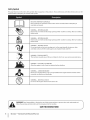
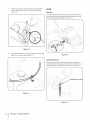
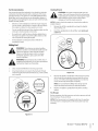
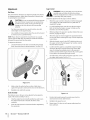
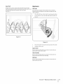
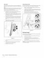
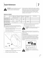
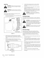
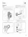
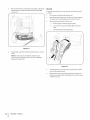
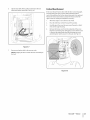
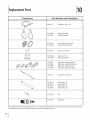
Safe Operation
Practices • Set-Up • Operation
• Maintenance
• Service • Troubleshooting
• Warranty
L
600-Series
Snow Thrower
m K Style
MTD LLC, P.O. BOX 361131 CLEVELAND, OHiO 44136-0019
PrintedIn USA
FormNo.769-04033
(JuLy2, 2008)
1
ToTheOwner
ThankYou
Thank you for purchasing
a Snow Thrower
manufactured
by
If you have any problems
MTD LLC. It was carefully engineered to provide excellent
performance
when properly operated and maintained.
Please read this entire manual
It instructs
prior to operating
your machine.
persons
who will operate
address and mailing
the equipment.
you how to safely and easily set up, operate
maintain
carefully
and
follow
concerning
address can be found
to ensure your complete
Please be sure that you, and any other
the machine,
or questions
Throughout
the
machine
satisfaction
this manual,
are observed
on this page. We want
at all times.
all references
to right and left side of the
from the operating
position.
recommended
safety practices at all times. Failure to do so could
result in personal injury or property damage.
The engine
All information
is relative to the most recent
warranty
at the time of printing.
Owner's/Operator's
Manual, packed separately
machine, for more information.
product
in this manual
information
available
the machine,
phone your local authorized MTD service dealer or contact us
directly. MTD's Customer Support telephone
numbers, website
Review
this manual frequently to familiarize yourself with the unit, its
features and operation.
Please be aware that this Operator's
manufacturer
is responsible
issues with regards to performance,
for all engine-related
power-rating,
and service. Please refer to the engine
specifications,
manufacturer's
with your
Manual may cover a range of product specifications
for various
models. Characteristics
and features discussed and/or illustrated
in this manual
may not be applicable
to all models.
MTD LLC
reserves the right to change product specifications,
designs and
equipment
without notice and without
incurring obligation.
Tableof Contents
Important
Safe Operation
Practices ......................
3
Assembly & Set-Up ..................................................
Controls & Features ................................................
7
11
Operation
14
................................................................
Maintenance
& Adjustment.
.................................
up and operating
plate by standing
at the lower, rear section
your new equipment,
at the operator's
should you seek technical
Customer
dealer.
Support
Department,
....................................................
25
Parts ................................................
26
Replacement
[3N[3N[3N[3N[3ND
please
position
and looking
of the frame. This information
necessary,
Troubleshooting
MODEL NUMBER
locate the model plate on the equipment
and record the
information
in the provided area to the right. You can locate the
model
19
21
16
RecordProductinformation
Before setting
Engine Maintenance
..............................................
Service .....................................................................
support
SERIAL NUMBER
will be
via our web site,
or with a local authorized
service
DNDNDNDNDND
CustomerSupport
Please
do NOT return
If you have difficulty
the unit
assembling
this unit, you can seek help from
to the retailer
without
this product
or have any questions
the experts.
Choose
0
Visit us on the web at www.mtdproducts.com
0
Call a Customer
0
Write
Support
or dealer
Representative
from
the options
at (800) 800-7310
us at MTD LLC • EO. Box 361131 • Cleveland,
first contacting
regarding
below:
or (330) 220-4683
OH • 44136-0019
our Customer
the controls,
Support
operation,
Department.
or maintenance
of
2
ImportantSafeOperationPractices
WARNING!
This symbol
could endanger
all instructions
points
the personal
safety and/or
in this manual
with these instructions
out important
before
property
attempting
may result in personal
When you see this symbol.
safety instructions
of yourself
to operate
which,
if not followed,
and others.
this machine.
Read and follow
Failure to comply
injury.
HEED ITS WARNING!
CALIFORNIA
PROPOSITION
65
WARNING! Engine Exhaust, some of its constituents,
and certain vehicle components
contain or emit chemicals known to State of California to cause cancer and birth defects
or other reproductive
DANGER: This machine
this manual.
operator
harm.
was built to be operated
As with any type of power
can result in serious injury. This machine
toes and feet and throwing
instructions
foreign
objects.
machine
assemble
and follow
all instructions
and in the manual(s) before
and operate.
and regular
Keep this manual
reference
on the
attempting
in a safe place for
and for ordering
replacement
foreign
1.
Never allow children under 14 years of age to operate this
machine. Children 14 and over should read and understand
and safe operation
and on the machine
adult.
5.
and be trained
Never allow adults to operate
instruction.
Thrown
objects
practices
this machine
can cause serious personal
Keep bystanders,
pets and children
machine while it is in operation.
enters the area.
Exercise caution
when operating
to avoid slipping
in reverse.
proper
injury. Plan
2.
hands,
safety
Stop machine
over or thrown
Always wear safety glasses or eye shields during
performing
Do not operate
Wear footwear
surfaces.
3.
an adjustment
without
wearing
which
by the
operation
or repair to protect
ricochet
can cause serious
adequate
will improve
Use a grounded
three-wire
for all machines
with electric
4.
Adjust collector
rock surfaces.
housing
5.
Disengage
6.
Never attempt
if anyone
running,
operator's
or falling, especially
could be tripped
winter
outer
garments. Do not wear jewelry, long scarves or other loose
clothing, which could become entangled in moving parts.
of material
at least 75 feet from the
which
your eyes. Thrown objects which
injury to the eyes.
by an
without
objects,
and while
in this manual
and supervised
your snow-throwing
pattern to avoid discharge
toward roads, bystanders and the like.
6.
fingers,
auger/impeller.
Be familiar with all controls and their proper operation.
Know how to stop the machine and disengage them
the instructions
4.
of amputating
Failure to observe the following
quickly.
3.
in
Thoroughly
inspect the area where the equipment
is to be used.
Remove all doormats, newspapers, sleds, boards, wires and other
to
parts.
2.
is capable
practices
or error on the part of the
Preparation
Read, understand,
future
to the safe operation
carelessness
could result in serious injury or death.
Training
1.
according
equipment,
7.
all control
footing
extension
on slippery
cord and receptacle
start engines.
height to clear gravel or crushed
levers before
starting
to make any adjustments
except where specifically
the engine.
while
recommended
engine is
in the
manual.
Let engine and machine adjust to outdoor
before starting to clear snow.
temperature
5.
SafeHandling of Gasoline
To avoid personal
in handling
injury or property
gasoline. Gasoline
vapors are explosive.
damage
is extremely
Serious personal
use extreme
flammable
a.
Use only an approved
b.
Extinguish all cigarettes,
Engine exhaust
care
and deadly
and the
6.
injury can occur when
gasoline is spilled on yourself or your clothes which
Wash your skin and change clothes immediately.
can ignite.
7.
gasoline container.
8.
cigars, pipes and other
d.
Never fuel machine
Never remove
9.
indoors.
gas cap or add fuel while
the engine
10.
Allow engine to cool at least two minutes
before
Never over fill fuel tank. Fill tank to no more than 1/2
inch below bottom
of filler
neck to provide
g.
Replace gasoline
h.
If gasoline is spilled, wipe it off the engine and
equipment.
Move machine to another area. Wait 5
i.
cap and tighten
before starting
or drugs.
Muffler
and engine
Exercise extreme
when
Exercise caution
or fuel container
to cool at least 5 minutes
inside
damage or personal
Never direct discharge
inside a vehicle
14.
Disengage power to the auger/impeller
or not in use.
15.
Never operate
or on a truck
equipment
4.
4
J
tank or container
at all times until fueling
Do not use a nozzle lock-open
Do not put hands or feet near rotating
impeller
housing
rotating
parts can amputate
or chute assembly.
control
Disengage
all control
levers and stop engine
position
(behind
it
Repair
comes to a complete
unclog
is
making
Always use the clean-out
the discharge
opening.
before you
the handles). Wait
Never put your hand in the discharge
openings.
stop before
any adjustments,
or collector
tool provided
Do not unclog
to
chute
assembly while engine is running. Shut off engine and
remain behind handles until all moving parts have stopped
device.
unclogging.
19.
Use only attachments
and accessories approved by the
manufacturer
(e.g. wheel weights, tire chains, cabs etc.).
20.
When starting engine, pull cord slowly until resistance
is felt, then pull rapidly. Rapid retraction of starter cord
parts, in the auger/
Contact with the
hands and feet.
lever is a safety device. Never
levers must operate
speeds on
and behind and use care
If the machine should start to vibrate abnormally,
stop
the engine, disconnect
the spark plug wire and ground
before
easily in both directions
return to the disengaged
position
IMPORTANT SAFE OPERATION
(kickback)
unsafe
when
will pull hand and arm toward engine
you can let go. Broken bones, fractures,
could result.
21.
If situations
occur which
care and good judgment.
are not covered
PRACTICES
faster than
bruises or sprains
in this manual,
Contact Customer
Support
assistance and the name of your nearest servicing
Never operate with a missing or damaged chute assembly.
Keep all safety devices in place and working.
SECTION 2 --
when transporting
at high transport
unclogging
the chute assembly,
or inspections.
18.
with the rim of the fuel
and automatically
released.
to clear
up.
until the auger/impeller
If this
nozzle.
opening
machine
surfaces. Look down
leave the operating
from
Keep the nozzle in contact
The control
by attempting
against the engine. Inspect thoroughly
for damage.
any damage before starting and operating.
17.
bypass its operation. Doing so makes the machine
and may cause personal injury.
3.
and pets or
away from your vehicle
remove gas-powered
dispenser
The auger/impeller
bystanders
in front of the machine.
Never operate this machine without good visibility or light.
Always be sure of your footing and keep a firm hold on the
handles. Walk, never run.
Operation
2.
at children,
caused by a ricochet.
13.
is not possible, then refuel such equipment
on a
trailer with a portable container, rather than from a
1.
injury
Do not overload machine capacity
snow at too fast of a rate.
bed with a plastic liner. Always place
complete.
and while
before
the truck or trailer and refuel it on the ground.
m.
direction
12.
16.
containers on the ground
before filling.
gasoline
when changing
on or crossing
hazards or traffic.
Plan your snow-throwing
pattern to avoid discharge
towards windows, walls, cars etc. Thus, avoiding possible
slippery
Never fill containers
If possible,
operating
on slopes.
when backing
I.
of
hot and can cause a burn. Do
away.
caution
the influence
is an open flame, spark or pilot light
Allow machine
storing.
or trailer
become
not touch. Keep children
allow anyone
dryer etc.).
k.
while under
area.
an odorless
securely.
(e.g. furnace, water heater, space heater, clothes
j.
monoxide,
the engine.
Never store the machine
where there
11.
space for
fuel expansion.
minutes
machine
alcohol
property
refueling.
f.
or in a poorly ventilated
carbon
gas.
Do not operate
operating
is
hot or running.
e.
indoors
contains
gravel surfaces. Stay alert for hidden
sources of ignition.
C.
Never run an engine
for
dealer.
use
Clearinga CloggedDischargeChute
service dealer to ensure that all mechanical
Hand contact
Failure to do so can result in accidents,
with the rotating
impeller
systems are working
inside the discharge
properly
chute is the most common cause of injury associated with snow
throwers. Never use your hand to clean out the discharge chute.
Donot modifyengine
To clear the chute:
To avoid serious injury
1.
SHUTTHE ENGINE OFF!
way. Tampering
2.
Wait 10 seconds to be sure the impeller
stopped rotating.
3.
Always use a clean-out
blades have
Never tamper
operation
adjustment
2.
disengage
all control
the auger/impeller
or inspecting
levers and stop the engine.
to keep the machine
Also, visually
4.
5.
inspect
against
the engine
are certified
regulations
to comply with California
are certified
to operate
may include
the following
on regular
unleaded
emission
_
condition.
for any damage.
exhaust
system is equipped
meeting
applicable
shave plates and skid shoes are subject to
frequently
and replace with original
equipment
manufacturer's
(OEM) parts only. "Use of parts which do
not meet the original equipment
specifications
may lead to
improper
performance
Check control
and compromise
levers periodically
and
safety!"
order by the operator.
with a spark arrester
local or state laws (if any).
working
For your safety protection,
gasoline,
systems: Engine
internal combustion
engine and should not be used
machine isforest-covered,
equipped with brush
an
on ARNING!
or near anyThis
unimproved
covered or grass-covered
land unless the engine's
Ira spark arrester is used, it should
speed of the engine.
check all components
control
Spark Arrestor
operating
Snow thrower
and federal
for SORE (Small Off Road Equipment)
Do not change the engine governor setting or over-speed
the engine. The governor controls the maximum safe
wear and damage.
6.
of engine
to
at frequent
in safe working
machine
Wait until
stop. Disconnect
Check bolts and screws for proper tightness
intervals
at unsafe speeds. Never tamper
governor.
setting
Modification
(EM), Oxidizing Catalyst (OC), Secondary Air
Injection (SAI) and Three Way Catalyst (TWC) if so equipped.
machine
come to a complete
the spark plug wire and ground
prevent unintended
starting.
3.
and
of this manual.
repairing,
in any
with factory
EPA emission
Refer to the maintenance
sections
Before cleaning,
engine
can lead to a runaway
engine and cause it to operate
Engines which
with safety devices. Check their proper
regularly.
setting
or death.
Notice RegardingEmissions
tool, not your hands.
Maintenance & Storage
1.
injuries
or death, do not modify
with the governor
and safety
and not worn excessively.
be maintained
in effective
In the State of California
the
above is required by law (Section 4442 of the California Public
Resources Code). Other states may have similar laws. Federal laws
apply on federal
lands.
A spark attester for the muffler
is available
through
your
nearest engine authorized service dealer or contact the service
department,
RO. Box 361131 Cleveland, Ohio 44136-0019.
to verify they engage
and disengage properly and adjust, if necessary. Refer
to the adjustment
section in this operator's manual for
instructions.
7.
Maintain
or replace
safety and instruction
labels, as
necessary.
8.
Observe proper disposal laws and regulations
etc. to protect the environment.
9.
Prior to storing,
from machine
10.
run machine
and prevent
Never store the machine
a few minutes
heater, furnace,
or fuel container
12.
inside where
light such as a water
clothes dryer etc.
Always refer to the operator's
instructions
to clear snow
freeze up of auger/impeller.
there is an open flame, spark or pilot
11.
for gas, oil,
on off-season
manual
for proper
storage.
Check fuel line, tank, cap, and fittings
frequently
for cracks
or leaks. Replace if necessary.
13.
Do not crank engine with spark plug removed.
14.
According
to the Consumer
Products
(CPSC) and the U.S. Environmental
this product
Safety Commission
Protection
Agency
(EPA),
has an Average Useful Life of seven (7) years,
or 60 hours of operation.
Life have the machine
At the end of the Average Useful
inspected
annually
by an authorized
SECTION
2 --
IMPORTANT
SAFE
OPERATION
PRACTICES
S
Safety Symbols
This page depicts and describes safety symbols that may appear
machine before attempting
to assemble and operate.
on this product.
Read, understand,
and follow
all instructions
on the
READ THE OPERATOR'S MANUAL(S)
Read, understand,
assemble
and follow
all instructions
in the manual(s) before
WARNING--
WARNING--
WARNING--
Contact
with the rotating
WARNING--THROWN
This machine
WARNING--
machine
is running.
There are rotating
parts, in the auger/impeller
SECTION 2 --
injury.
before refueling.
or in a poorly ventilated
area. Engine exhaust contains carbon
ELECTRICAL SHOCK
Your Responsibility--Restrict
IMPORTANT SAFE OPERATION
can cause serious personal
IS FLAMMABLE
electric starter in the rain
the use of this power machine
to persons
in this manual and on the machine.
SAVETHESEINSTRUCTIONS!
I
or chute
an odorless and deadly gas.
Do not use the engine's
6
housing
hands and feet.
CARBON MONOXIDE
WARNING--
and instructions
while
OBJECTS
Never run an engine indoors
the warnings
There are rotating
parts can amputate
Allow the engine to cool at least two minutes
follow
is running.
may pick up and throw and objects which
WARNING--GASOLINE
monoxide,
machine
ROTATING AUGER
Do not put hands or feet near rotating
assembly.
while
ROTATING BLADES
Keep hands out of inlet and discharge openings
blades inside
WARNING!
to
ROTATING BLADES
Keep hands out of inlet and discharge openings
blades inside
........
!i........
attempting
and operate
PRACTICES
who read, understand
and
3
Assembly
& Set-Up
Contentsof Carton
One Snow Thrower
One Snow Thrower
Manual
Two Replacement
Auger Shear Pins
One Product
Operator's
Assembly
Handle
1.
Place the shift lever in the Forward-6
position
2.
Observe the lower rear area of the snow thrower
to be sure
both cables are aligned with roller guides
the handle upward. See Fig. 3-1.
pivoting
before
Figure 3=2
Figure 3-1
NOTE: Make certain the upper ends of each cable are
seated properly
3.
in its bracket.
Secure the handle by tightening
the plastic knob located
on both the left and right sides of the handle.
and discard any rubber
packaging
purposes
Remove
bands, if present. They are for
only.
ChuteAssembly
1.
Remove wing nuta nd hex screw from chute control assembly
and clevis pin and cotter pin from chute support bracket.
Position the chute assembly
chute base. See Fig. 3-2.
2.
Place chute assembly
control
assembly
and cotter
(forward-facing)
over the
onto chute base and secure chute
to chute support
pin removed
bracket with clevis pin
earlier. See See Fig. 3-3.
Figure
3=3
Registration
Card
3
Finish securing
bracket
chute control assembly
to chute support
with wing nut and hex screw removed
earlier.
Set-Up
ShearPins
See Fig. 3-4.
A pair of replacement
auger shear pins and bow tie cotter
are included with your snow thrower. Store them
thrower's dash panel until needed. See Fig. 3-6.
pins
in your snow
Figure 3-4
4.
Check that all cables are properly routed through
guide on top of the engine. See Fig. 3-5.
the cable
Figure 3-6
Chute Clean-0ut Tool
The chute clean-out
housing
tool is fastened
with a mounting
the cable tie before
to the top of the auger
clip and a cable tie at the factory.
operating
the snow thrower.
Cut
See Fig. 3-7.
f
Chute Clean=out Too
Figure 3-5
J
Figure 3-7
8
I
SECTION3--
ASSEMBLY&
SET-UP
Fuel Recommendations
Use automotive
combustion
gasoline
chamber
Gasoline with
CheckingOil Level
(unleaded
deposits)
or low leaded to minimize
with a minimum
up to 10% ethanol
of 87 octane.
or 15% MTBE (Methyl
Tertiary
engine. You must, however, check the oil level prior
is shipped
with oil
the
to AUTION:
operating The
the engine
snow thrower.
Running
thein engine
_1
Butyl Ether) can be used. Never use an oil/gasoline
mixture or
dirty gasoline. Avoid getting dirt, dust, or water in the fuel tank.
DO NOT use E85 gasoline.
area with the engine stopped.
Do not smoke or allow flames or sparks in the area where
the engine is refueled or where gasoline is stored.
the fuel tank. After refueling,
tank cap is closed properly
fuel vapor may ignite.
Avoid repeated
breathing
make sure the
and securely.
Be careful not to spill fuel when
area is dry before
oil can cause serious engine
damage and void the engine warranty.
NOTE: Be sure to check the engine
Refuel in a well-ventilated
Do not overfill
with insufficient
refueling.
Spilled fuel or
If any fuel is spilled,
make sure the
starting
on a level surface with the
engine stopped.
1.
Remove the oil filler cap/dipstick
and wipe the dipstick
clean. See Fig. 3-9.
2.
Insert the cap/dipstick
screw it in.
into the oil filler neck, but do not
the engine.
or prolonged
contact
with skin or
of vapor.
AddingFuel
WARNING!
Use extreme
care when
handling
gasoline. Gasoline is extremely flammable
and the
vapors are explosive.
Never fuel the machine
indoors
or while
Extinguish
the engine
cigarettes,
is hot or running.
cigars, pipes and other
sources of ignition.
WARNING!
Always keep hands and feet clear of
equipment
moving parts. Do not use a pressurized
starting fluid. Vapors are flammable.
1.
Clean around
2.
A fuel level indicator
fuel fill before
removing
is located
cap to fuel.
in the fuel tank. Fill tank
until fuel reaches the fuel level indictor,
not to overfill.
Figure
Fig. 3-8. Be careful
3.
3=9
Remove the oil filler cap/dipstick.
If the level is low, slowly
add oil until oil level registers between high (H) and low
(L), Fig. 3-9. Refer to the Engine Maintenance
correct
oil viscosity
and engine
section for
oil capacity.
NOTE: Do not overfill. Overfilling with oil may result in
engine smoking, hard starting or spark plug fouling.
4.
Replace and tighten
cap/dipstick
firmly
before
starting
engine.
Fuel Level Indicator
Top View
TirePressure
Before operating,
tires to between
check tire pressure and reduce pressure in both
15 psi and 20 psi.
NOTE: If the tire pressure is not equal in both tires, the machine
may not travel in a straight
path and the shave plate may wear
unevenly.
Figure 3-8
SECTION
3 --
ASSEMBLY& SET-UP
9
AugerControl
Adjustments
SkidShoes
carefully
The snow thrower
skid shoes are adjusted
upward
for shipping
to operating
purposes. Adjust them downward,
the snow thrower.
if desired,
i_
this snow thrower on gravel as it can easily pick up
CAUTION:
It is not
recommended
thatyouinjury
operate
and
throw loose
gravel,
causing personal
or
prior
is operating
Check the adjustment
1.
damage to the snow thrower
on a smooth
should
is uneven,
or lower position
is released
the cable should
and in the disengaged
have very little slack. It
NOT be tight.
surface, raise skid
In a well-ventilated
area, start the snow thrower engine.
Refer to Starting the Engine on page 14. Make sure the
throttle
is set in the FAST position.
when
the area to be cleared
While standing
thrower),
in the operator's
position
(behind
the snow
engage the auger.
such as a gravel driveway
NOTE: If you choose to operate
the snow thrower
4.
Allow the auger to remain engaged for approximately
ten
(10) seconds before releasing the auger control. Repeat this
several times.
5.
With the throttle
on a gravel
surface, keep the skid shoes in position for maximum
between the ground and the shave plate.
clearance
To adjust the skid shoes:
1.
control as follows:
housing.
3.
Use a middle
below.
safely and properly.
of the auger
When the auger control
"up" position,
2.
shoes higher on the auger
all instructions
and surrounding
property.
For close snow removal
read and follow
WARNING!
Prior to operating
Perform all adjustments
to verify your
your snow
snow thrower,
thrower
at the factory
Loosen the four hex nuts (two on each side) and carriage
bolts. Move skid shoes to desired position.
See Fig. 3-10.
control
in the FAST (rabbit)
the auger control in the disengaged
the front of the machine.
6.
position
"up" position,
and
walk to
Confirm that the auger has completely
stopped rotating
and shows NO signs of motion. If the auger shows ANY
signs of rotating,
position
immediately
return to the operator's
and shut off the engine.
to stop before
re-adjusting
Wait for ALL moving
the auger
parts
control.
/
!
/
7.
To readjust the control cable, loosen the upper
the auger cable bracket. See Fig. 3-11.
hex nut on
f
,\
i'
\
\
\
Figure 3-10
\
\
\
\,
2.
Make certain the entire bottom
against the ground
3.
Retighten
surface of skid shoe is
to avoid uneven
wear on the skid shoes.
nuts and bolts securely,
k_
ChuteAssembly
The distance
Figure 3-11
snow is thrown
angle of the chute assembly.
1.
Stop the engine
can be adjusted
the
To do so:
by removing
the plastic knob found
by changing
8.
the ignition
on the left side of the chute
assembly.
2.
,°I
Pivot the chute upward
the wing knob.
SECTION
3--
ASSEMBLY&
or downward
SET-UP
before
retightening
Position
downward
key and loosen
the bracket
upward
to increase
to provide
9.
Retighten
10.
Repeat steps 2-6 above to verify
been achieved.
the upper
more slack (or
cable tension).
hex nut.
proper adjustment
has
4
Controls
and Features
Shift Lever
/
Drive Control
Chute Directional
Control
er Control
Gas Cap
\
Chute Assembly
Heated Grips_
\
\,
OU FUl
\
\
Clean Out
Tool
Muffler
\
\
Recoil Starter
Handle
Ignition
Key
/
Throttle
Control
Choke
Control
Augers
/
Oil Drain
Skid Shoe
Electric Start
Button
Electric Starter Outlet
Figure 4=1
Snow thrower
illustrated
controls
and features
are described
below and
ChokeControl
in Fig. 4-1.
The choke control
Shift Lever
6
The shift lever is located in the right side of the
handle panel and is used to determine
ground
5
speed and direction
4
Forward
3
There are six forward
the slowest
(F) speeds. Position
and position
Reverse
and aids
the engine.
Ignition Key
The ignition key is a safety device. It must
be fully inserted in order for the engine to
one (1) is
six (6) is the fastest,
on the rear of
the choke plate on the carburetor
in starting
of travel.
is found
the engine and is activated by rotating the
knob. Activating
the choke control closes
t
2
F 1
start. Remove the ignition key when
snow thrower is not in use.
There are two reverse (R) speeds. One (1) is the
Note: Do not turn the ignition
slower and two (2) is the faster.
attempt to start the engine.
cause it to break.
R1
the
key in an
Doing so may
R2
11
ThrottleControl
AugerControl
f
AUGER
CONTROL
The throttle
control
regulates
the speed
when
moved
is located on the rear of the engine.
It
of the engine and will shut off the engine
into the STOP position.
Primer
Pressing the primer
into the engine's
weather starting.
forces fuel directly
carburetor
%_p_li
to aid in cold|
Oil Fill
The auger control
Engine oil level can be checked and oil added through
the oil fill.
is located
on the left handle.
Squeeze the
control grip against the handle to engage the augers and start
snow throwing
action. Release to stop.
Oil Drain
DriveControl / AugerClutchLock
Engine oil can be drained
through
the oil drain.
f
Muffler
Engine exhaust
exists the engine
DRIVE
CONTROL
via the muffler.
Skid Shoes
Position
the skid shoes based on surface
upward
for hard-packed
operating
conditions.
snow. Adjust downward
on gravel or crushed
Adjust
when
rock surfaces.
Electric Starter Outlet
Requires the use of a three-prong
120V power source/wall
outdoor
extension
cord and a
outlet.
Recoil Starter Handle
The drive control
This handle is used to manually
control
start the engine.
is located
on the right handle.
Squeeze the
grip against the handle to engage the wheel drive.
Release to stop.
Electric Starter Button
Pressing the electric
starter when
starter
plugged
button
engages
the engine's
electric
The drive control also locks the auger control so that you can
operate the chute directional
control without interrupting
the snow throwing
into a 120V power source.
simultaneously
Augers
When engaged,
the augers rotate and draw snow into the auger
process. If the auger control
with the drive control,
is engaged
the operator
can release
the auger control (on the left handle) and the augers will remain
engaged. Release both controls to stop the augers and wheel
drive.
housing.
Note:Always
ChuteAssembly
drive system.
Snow drawn into the auger housing
is discharged
out the chute
assembly.
GasCap
Unthread
12
J
the gas cap to add gasoline to the fuel tank.
SECTION 4 --
release the drive control
Failure to do so will result in increased
CONTROLS AND FEATURES
before
changing
speeds.
wear on your machine's
Chute DirectionalControl
CHUTE
Chute Clean-Out Tool
DiRECTiONAL
CONTROL
clogged chute assembly. Shut off engine and remain
ARNING!
Never
hands
to clear
behind
handles
until use
all your
moving
parts
have a
stopped
_
before
unclogging.
The chute clean-out
the auger
CHUTE
ROTATE
LEFT
is located
fastened
to the rear of
clip. Should snowand
1.
Release both the Auger Control
2.
Stop the engine
3.
Remove the clean-out tool from the clip which
the rear of the auger housing.
4.
Use the shovel-shaped
J
control
tool is conveniently
with a mounting
ice
become lodged in the chute assembly during operation,
proceed
as follows to safely clean the chute assembly and chute opening:
CHUTE
ROTATE
RIGHT
The chute directional
housing
on the left side of the
dislodge
dash panel.
by removing
and the Drive Control.
the ignition
key.
end of the clean-out
and scoop any snow and ice which
secures it to
tool to
has formed
in
and near the chute assembly.
To change
the direction
the button
on the joy-stick
in which
snow is thrown,
and pivot the joy-stick
squeeze
to the
right or to the left.
5.
Refasten the clean-out
While standing
HeatedGrips*
tool to the mounting
rear of the auger housing, reinsert
start the snow thrower's engine.
thrower),
remaining
in the operator's
position
engage the auger control
clip on the
the ignition
(behind
key and
the snow
for a few seconds to clear any
snow and ice from the chute assembly.
0
To activate the heated grips (%n select models), move the switch
found on the rear of the dash panel into the ON position.
SECTION4
--
CONTROLS AND FEATURES
13
Operation
Starting the Engine
l_lhllL
starting.
operating
The engine
Plug the extension
engine.
to warm up for a few minutes
will not develop
cord into the electric outlet located on the
Plug the other
end of extension
prong 120-volt, grounded,
area. See Fig. 5-2.
moving parts. Do not use a pressurized starting
ARNING!
Always
keep hands and feet clear of
fluid.
Vapors are
flammable.
Allow the engine
NOTE:
3.
AC outlet
cord into a three-
in a well-ventilated
after
full power until it reaches
temperatures.
ElectricStarter
WARNING!
The electric
grounded
three-wire
designed
to operate
starter
is equipped
with a
power cord and plug, and is
on 120 volt AC household
current. It must be used with a properly grounded
three-prong
receptacle at all times to avoid the
possibility
of electric
carefully prior to operating the electric
DO NOT use electric starter in rain.
1.
\
shock. Follow all instructions
Determine
that your home's wiring
grounded
system. Ask a licensed
\/
J
starter.
is a three-wire
electrician
if you are
unsure. If you have a grounded three-prong
receptacle,
proceed as follows. If you do not have the proper house
wiring, DO NOT use the electric
conditions.
2.
Insert ignition
starter
under any
key fully into slot, Fig. 5-1. Make sure it snaps
into place. DO NOTturn ignition key. The engine cannot
start unless the key is inserted into ignition switch.
Figure 5-2
4.
Move throttle
control to FAST (rabbit)
5.
Move choke to the ON position
position.
(cold engine start). Ifengine
is
warm, place choke in OFF position.
6.
Push primer
three to five (3-5) times, making
vent hole when
pushing.
sure to cover
If engine is warm, push primer
only once. Always cover vent hole when pushing.
weather
7.
may require
Push starter
button
starts, immediately
is equipped
priming
to start engine.
release starter
with thermal
Cool
to be repeated.
overload
Once the engine
button.
Electric starter
protection;
system will
temporarily
shut-down
to allow starter to cool if electric
starter becomes overloaded.
8.
As the engine
warms, slowly rotate the choke control
OFF position.
If the engine falters, restart engine and run
with choke at half-choke
position
for a short period
to
of time,
and then slowly rotate the choke into OFF position.
9.
After engine
electric
is running,
end at the wall outlet
from the engine.
Figure 5-1
disconnect
starter. When disconnecting,
before
power cord from
always unplug
unplugging
the
the opposite
end
RecoilStarter
ToEngageDrive
1.
With the throttle control in the Fast(rabbit) position, move
shift lever into one of the six forward (F) positions or two
reverse (R) positions. Select a speed appropriate for the
snow conditions and a pace you're comfortable with.
2.
Squeeze the drive control against the handle the snow
thrower will move. Release it and drive motion will stop.
engine running.
CAUTION! Do not pull the starter handle while the
WARNING: To avoid unsupervised engine
operation, never leave the engine unattended while
running. Turn the engine off after use and remove
ignition key
ToEngageAugers
Insert ignition key fully into slot, Figure 5-5. Make sure it
snaps into place. DO NOTturn ignition key.The engine
cannot start unless the key is inserted into ignition switch.
To engage the augers and start throwing
snow, squeeze
the auger control
Release to stop
ReplacingShearPins
Move throttle control to FAST(rabbit) position.
3.
Move choke to the ON position (cold engine start). If engine
is warm, place choke in OFF position.
The augers are secured
Push primer three to five (3-5) times, making sure to cover
vent hole when pushing. If engine is warm, push primer
only once. Always cover vent hole when pushing. Cool
weather may require priming to be repeated.
jam, the snow thrower
5.
6.
and cotter
to the spiral shaft with two shear pins
pins. If the auger should strike a foreign
is designed
object
or ice
so that the pins may shear. If
the augers will not turn, check to see if the pins have sheared.
See Fig. 5-3.
anything
Pull gently on the starter handle until it begins to
resist, then pull quickly and forcefully to overcome the
compression. Do not release the handle and allow it to
snap back. Return rope SLOWLYto original position. If
required, repeat this step.
As the engine warms, slowly rotate the choke control to
OFF position. If the engine falters, restart engine and run
with choke at half-choke position for a short period of time,
and then slowly rotate the choke into OFF position.
the left handle.
the augers.
2.
4.
against
other than OEM Part No. 738-04124A
CAUTION:
replacement
gearbox
NEVER
shear pins.
replace
Anythe
damage
auger to
shear
the pins
augerwith
or other components
do so will NOT be covered
as a result of failing
to
by your snow thrower's
war ranty.
_
engine and remove the key prior to replacing shear
WARNING!
Always turn off the snow thrower's
pins.
Stopping the Engine
_
--
operation, never leave the machine unattended
ARNING:
To avoid
unsupervised
engineoff after
with
the engine
running.
Turn the engine
use and remove ignition key
Run engine for a few minutes before stopping to help dry offany
moisture on the engine.
1.
Move throttle control to STOP position.
2.
Remove the ignition key. Removing the key will reduce the
possibility of unauthorized starting of the engine while
equipment is not in use. Keep the key in a safe place. The
engine cannot start without the ignition key.
3.
Wipe any moisture away from the controls on the engine.
,J
Figure 5-3
SECTION
S --
OPERATION
15
6
Maintenance& Adjustments
Maintenance
Lubrication
Engine
GearShaft
Refer to the Engine Maintenance
section.
The gear (hex) shaft should
or after every twenty-five
ShavePlate and Skid Shoes
The shave plate and skid shoes on the bottom
thrower
are subject to wear. They should
and replaced
To remove
when
be checked periodically
1.
Allow the engine to run until it is out of fuel.
2.
Carefully pivot the snow thrower
rests on the auger housing.
3.
Remove the frame cover from the underside
necessary.
1.
Remove the four carriage bolts and hex flange nuts which
secure them to the snow thrower.
2.
Reassemble
4.
new skid shoes with the four carriage bolts
up and forward
thrower by removing
it. Refer to Fig 7-3.
four self-tapping
Apply a light coating
shaft. See Fig. 6-2.
of engine
so that it
of the snow
screws which
secure
oil (or 3-in-1 oil) to the hex
nuts. Refer to Fig. 6-1.
NOTE:When
To remove
at least once a season
of the snow
skid shoes:
(two on each side) and hex flange
be lubricated
(25) hours of operation.
shave plate:
lubricating
any oil on the aluminum
the hex shaft, be careful not to get
drive plate or the rubber friction
wheel. Doing so will hinder the snow thrower's
system. Wipe off any excess or spilled
drive
oil.
\
NOTE: Augers not shown for clarity
,.
j
Figure 6-1
3.
Remove the carriage
the snow thrower
4.
Reassemble
bolts and hex nuts which
attach it to
Figure 6-2
housing.
new shave plate, making
bolts are to the inside of housing.
sure heads of carriage
Tighten
securely.
Wheels
Tire Pressure
At least once a season, remove both wheels.
Before operating,
axles with a multipurpose
wheels.
between
check tire pressure and reduce pressure to
15 psi and 20 psi.
If the tire pressure is not equal in both tires, the unit may pull to
one side or the other.
automotive
Clean and coat the
grease before
reinstalling
Auger Shaft
Adjustments
At least once a season, remove the shear pins from the auger
shaft. Spray lubricant
the flange bearings
See Fig. 6-3.
inside the shaft and around
found
the spacers and
at either end of the shaft.
Shift Cable
If the full range of speeds (forward
and reverse) cannot be
achieved, refer to the figures to the right and adjust
cable as follows:
the shift
1.
Place the shift lever in the fastest forward
2.
Loosen the hex nut on the shift cable index bracket.
speed position.
See
..........................
.......................
.....................
...................
...................
Fig. 6-4.
F
J
Figure 6-3
Figure 6-4
3.
Pivot the bracket
4.
Retighten
downward
to take up slack in the cable.
the hex nut.
Auger Control
Refer to the Assembly
adjusting
and Set-up section
the auger control
for instructions
on
for instructions
on
for instructions
on
cable.
ChuteAssembly
Refer to the Assembly
adjusting
and Set-up section
the skid shoes chute assembly.
Skid Shoes
Refer to the Assembly
adjusting
and Set-up section
the skid shoes.
SECTION 6 --
MAINTENANCE
& ADJUSTMENTS
17
DriveControl
Chute DirectionalControl
When the drive control
position,
is released
the cable should
and in the disengaged
have very little slack. It should
"up"
If the chute assembly
NOT be
the chute control
tight.
1.
NOTE: If excessive
slack is present in the drive cable or if the snow
thrower's drive is disengaging
intermittently
the cable may be in need of adjustment.
Check the adjustment
1.
2.
forward.
2.
released,
The unit should
to take up slack:
loosen the upper
and lower hex nuts
on one cable adjuster.
Grasp the metal cable housing
and gently
pull downward
to take up slack (usually no more than 1/4-inch) in the cable
before
push the snow thrower
3.
roll freely.
retightening
both
hex nuts.
Repeat on the other cable adjuster
assembly
until the chute
has full range from left-to-right.
See Fig. 6-6.
Engage the drive control and gently attempt to push the
snow thrower forward. The wheels should not turn. The
unit should
3.
operation,
Using a 1/2"wrench,
found
of the d rive control as follows:
With the drive control
gently
during
does not have full range from left-to-right,
cables can be adjusted
not roll freely.
With the drive control
released,
move the shift lever back
and forth between the R2 position and the F6 position
several times. There should be no resistance in the shift
lever.
4.
If any of the above tests failed, the drive cable is in need of
adjustment.
Proceed as follows:
Figure 6-6
Off-SeasonStorage
If the snow thrower
the storage
1.
will not be used for 30 days or longer, follow
instructions
Lubricate
below.
the machine
as instructed
earlier in this section.
Store in a clean, dry area.
Figure 6-5
5.
3.
Loosen the lower hex nut on the drive cable bracket.
6.
Position
4.
the bracket
downward
7.
rustproof the machine
the snow thrower.
See
Fig. 6-5.
Retighten
SECTION 6 --
upward
to increase
the upper
to provide
more slack (or
cable tension).
hex nut.
MAINTENANCE
& ADJUSTMENTS
If storing the snow thrower
Clean the exterior
in an unventilated
to coat
of the engine and the snow thrower.
NOTE: Refer to the Engine Maintenance
on storing your engine.
area,
using a light oil or silicone
section for information
7
EngineMaintenance
WARNING!
To prevent
accidental
the engine and remove the ignition
performing
any type of engine
start-up,
shut off
Periodic
inspection
and adjustment
high level performance
key before
of the engine is essential
is to be maintained.
will also ensure a long service life. The required
maintenance.
if
Regular maintenance
service intervals
and the type of maintenance
to be performed are described
in the table below. Follow the hourly or calendar intervals,
whichever
occur first. More frequent
operating
in adverse
service is required
when
conditions.
MaintenanceSchedule
Tasks
First 5 HrSl
-
Check engine
Each Use or
' Every Season
Every 5 Hrs.
or25 Hrs.
oil
Change engine
0il
I
I
or 100 Hrs.
I
"
•
I
area
I
I
I
I
•
6.
Changing Engine0il
Refill with the recommended
refer to Operation
NOTE: Check the oil level before each use and after every five
hours of operation to be sure correct oil level is maintained.
Refer
to Checking
1.
-
®
Spark plug
Clean exhaust
or 50 Hrs.
•
Check spark plug
service
Every Season
Oil Level in the Operation
Drain fuel from
tank by running
Reinstall
the oil filler cap/dipstick
securely.
section
engine until the fuel tank is
empty. Be sure fuel fill cap is secure.
oil collection
7.
oil and check the oil level,
section for instructions.
2.
Place suitable
container
3.
Remove oil drain plug, Figure 7-1.
_
and water as soon as possible after handling
used
AUTION:
oil.
Thoroughly
wash your hands with soap
under oil drain plug.
NOTE: Pleasedispose of used motor oil in a manner that is
friendly to the environment. Take it to a recyling center or other
collection center.
Oil Recommendations
When adding
oil to the engine,
Engine oil capacity
Use a 4-stroke,
quality motor
manufacturer's
refer to viscosity
is 600 ml (approx.
or an equivalent
chart below.
20 oz.). Do not over-fill.
high detergent,
premium
oil certified to meet or exceed U.S. automobile
requirements
for service classification SG, SF.
Motor oils classified
container.
SG, SF will show this designation
on the
Oil Drain
Oil Plug
@
(oF)-40o-20 o 0o 200 400
(oc)
-30 ° -20° -10°
0
Figure 7-1
4.
5.
Tip engine to drain oil into the container.
disposed
of at a proper collection
Reinstall
the drain plug and tighten
Used oil must be
2-stroke engine oil. It could shorten the engine's
CAUTION"
service life. DO NOT use nondetergent
oil or
center.
it securely.
19
5park Plug
4.
Check that the spark plug washer is in good condition
and thread
the spark plug in by hand to prevent
cross-
threading.
plug removed. DO NOT crank engine with spark
WARNING?
plug removed. DO NOT check for spark with spark
i_
5.
After the spark plug is seated, tighten
wrench
to compress
NOTE:When
To ensure proper
engine operation,
properly
and free of deposits.
1.
gapped
the spark plug must be
installing
a new spark plug, tighten
1/2-turn
after the spark plug seats to compress the washer. When
reinstalling
a used spark plug, tighten Vs- to 1/4-turn after
muffler will be very hot. Be careful not to touch the
WARNING!
muffler.
If the engine has been running, the
i_
with a spark plug
the washer.
the spark plug seats to compress
the washer.
securely. A loose spark plug can become very hot
CAUTION!
The spark
plug must be tightened
and
can damage
the engine.
_hL
Remove the spark plug boot and use a spark plug wrench
to remove the plug, Figure 7-2.
Cleaning the Engine
If the engine
has been running,
an hour before
Spark Plug
cleaning.
allow it to cool for at least half
Periodically
remove dirt build-up
from
engine.
because water could contaminate
CAUTION!
garden hose
also force water into the muffler
/
fuel. Using a
Do
or pressure
not spray washing
engine with
equipment
water tocan
clean
passes through
the muffler
opening.
Water that
can enter the cylinder,
causing damage.
could cause a fire. Inspect and clean before every
use.
ARNING!
Accumulation
of debris around muffler
_
Off-SeasonStorage
Engines stored over 30 days need to be drained
Spark Plug Boot
prevent
J
Figure 7-2
deterioration
Visually inspect the spark plug. Discard the spark plug
if there is apparent
chipped.
reused.
3.
f
wear, or if the insulator
is cracked or
Clean the spark plug with a wire brush if it is to be
and other fuel system components,
serviced
or
replaced.
1.
Remove all fuel from tank by running
2.
Change the engine
engine
3.
Remove spark plug and pour approximately
until it stops.
oil.
Measure the plug gap with a feeler gauge. Correct as
of clean engine
necessary by bending side electrode, Figure 7-3. The gap
should be set to .02-.03 inches (0.60-0.80 mm).
several times to distribute
Electrode
of fuel to
in fuel system
or on essential carburetor parts. If the gasoline in your engine
deteriorates
during storage, you may need to have the
carburetor,
2.
and gum from forming
oil into the cylinder.
1 oz. (30 ml)
Pull the recoil starter
the oil, and reinstall the spark
plug.
4.
Clean debris from around
behind
muffler.
are susceptible
Apply
engine,
and under, around,
a light film ofoil
to rust.
Store in a clean, dry and well ventilated
appliance
and
on any areas that
that operates
area away from any
with a flame or pilot light, such as a
furnace, water heater, or clothes dryer. Avoid any area with
a spark producing
electric motor, or where power tools are
operated.
_____
.__
•
=.
" .
(0.60-0.80 ram)
Figure 7-3
SECTION
7
--
ENGINE MAINTENANCE
If possible,
avoid storage
Keep the engine
oil leakage.
areas with
high humidity.
level in storage. Tilting
can cause fuel or
Service
Belt Replacement
4.
Auger Belt
5.
Carefully
pivot the snow thrower
up and forward
so that it
rests on the auger housing.
To remove and replace your snow thrower's
as follows:
thrower by removing
it. See Fig 8-3.
auger belt, proceed
I.
Allow the engine to run until it is out of fuel.
2.
Remove the plastic belt cover on the front of the engine by
removing the two self-tapping
screws. See Fig. 8-I.
/
Remove the frame cover from the underside
four self-tapping
of the snow
screws which
secure
/
i
/
/
/
\\
Figure 8-3
6.
Remove the belt as follows.
a.
See Fig. 8-4.
Loosen and remove the shoulder
screw which acts
asa belt keeper.
Unhook the support bracket spring from the frame.
Roll the auger
belt off the engine
pulley. See Fig. 8-2.
Figure 8-4
Figure 8-2
21
3_
Remove the belt from around
belt between
the support
the auger pulley, and slip the
bracket
and the auger pulley.
DriveBelt
To remove and replace your snow thrower's
as follows:
See Fig. 8-5.
drive belt, proceed
1.
Place a piece of plastic under the gas cap.
2.
Remove the plastic belt cover on the front of the engine by
removing the two self-tapping
screws. Refer to Fig. 8-1.
3.
Remove the belt as follows.
See Fig. 8-6.:
a.
Roll the auger
belt off the engine
b.
Use a wrench
right.
c.
Lift the drive belt offengine
pulley.
to pivot the idler pulley toward the
pulley
/
J
Figure 8-5
4_
Reassemble auger belt by following instructions in reverse
order.
NOTE: Do not forget
and reconnect
replacement
to reinstall the shoulder
screw
the spring to the frame after installing
a
auger belt.
Figure 8-6
4.
Carefully pivot the snow thrower
rests on the auger housing.
5.
Remove the frame cover from the underside
thrower
by removing
it. Refer to Fig. 8-3.
SECTION
8
--
SERVICE
up and forward
four self-tapping
so that it
of the snow
screws which
secure
6_
Slip the drive belt offthe
pulley and between
wheel and friction
disc. See Fig. 8-7.
wheel
Friction WheelRemoval
friction
If the snow thrower
fails to drive with the drive control engaged,
and performing
the drive control cable adjustment
fails to
correct the problem, the friction wheel may need to be replaced.
Follow the instructions
below. Examine the friction wheel for
signs of wear or cracking
and replace if necessary:
1.
Allow the engine to run until it is out of fuel.
2.
Place the shift lever in third Forward
3.
Carefully
pivot the snow thrower
(F3) position.
up and forward
so that it
rests on the auger housing.
4.
Remove the frame cover from the underside
of the snow
thrower by removing four self-tapping
screws which secure
it. Remove the right-hand wheel by removing the screw
and bell washer which
secure it to the axle. See Fig. 8-8.
Figure 8-7
Remove and replace
NOTE: Engaging
the belt.
belt in the reverse order.
the drive control
will ease reassembly
of
Figure 8-8
SECTION
8
--
SERVICE
23
5_
Carefully
remove the hex nut which
to the snow thrower
secures the hex shaft
frame and lightly
dislodge the ball bearing
See Fig. 8-9.
tap the shaft's end to
from the right side of the frame.
Follow the previous
components.
replacing
1.
NOTE: Be careful not to damage the threads
on the shaft.
steps in reverse order to reassemble
If you're
disassembling
the friction
only the rubber ring, proceed
Remove the four screws which
side plates together.
wheel and
as follows:
secure the friction
wheel's
See Fig. 8-11.
f
Figure 8-9
6_
Figure 8-11
Carefully position the hex shaft downward
and to the left
before carefully sliding the friction wheel assembly off the
2.
Remove the rubber
3.
Reassemble
ring from between
the plates.
the side plates with a new rubber
ring.
shaft. See Fig. 8-10.
NOTE:When
NOTE: If you're
replacing
the friction
wheel assembly
as a
reassembling
make sure that the rubber
whole, discard the worn part and slide the new part onto
the hex shaft.
properly
between
the friction
wheel assembly,
ring is centered
and seated
the side plates. Tighten
each screw
only one rotation before turning the wheel clockwise
and proceeding with the next screw. Repeat this process
several times to ensure the plates are secured
force (between 6 ft-lbs and 9 ft-lbs).
4.
Slide the friction wheel assembly back onto the hex shaft
and follow the steps above in reverse order to reassemble
components.
Figure 8-10
SECTION
8
--
SERVICE
with equal
9
Troubleshooting
Problem
Cause
Engine fails to start
1.
Remedy
Choke not in ON position.
1. Move choke to ON position.
2. Spark plug wire disconnected.
2. Connect wire to spark plug.
3. Fuel tank empty or stale fuel.
3. Fill tankwith
4. Engine not primed.
4. Prime engine as instructed
Your Snow Thrower".
clean, fresh gasoline.
in "Operating
5. Faulty spark plug.
5. Clean, adjust gap, or replace.
6. Safety key not in ignition
Engine runs erratic
1. Engine running
on engine.
on CHOKE.
6. insert key fully into the switch.
1. Move choke lever to OFF position.
2. Stale fuel.
2. Fill tank with clean, fresh gasoline.
3. Water or dirt in fuel system.
3. Drain fuel tank. Refill with fresh fuel.
4. Carburetor
out of adjustment.
4. Contact an authorized
Service Center.
Engine overheats
1. Carburetor
notadjusted
properly.
1. Contact an authorized
Service Center.
Excessive vibration
1. Loose parts or damaged
auger.
1. Stop engine immediately
spark plug wire. Tighten
and disconnect
all bolts and nuts. If
vibration continues, have unit serviced by an
authorized Service Center.
Loss of power
Unit fails to propel itself
Unit fails to discharge
snow
1. Spark plug wire loose.
1. Connect and tighten
2. Gas cap vent hole plugged.
2. Remove ice and snow from gas cap. Be
certain vent hole is clear.
1. Drive control cable in need of adjustment.
1. Adjust drive control cable. Refer to
Maintenance and Adjustments section.
2. Drive belt loose or damaged.
2. Replace drive belt. Refer to Service section
3. Friction wheel worn.
3. Replace friction
section.
1. Chute assembly
1,
clogged.
spark plug wire.
wheel. Refer to Service
Stop engine immediately
and disconnect
spark plug wire. Clean chute assembly and
inside of auger housing
or a shck.
2. Foreign object
lodged in auger.
2.
Stop engine immediately
with clean-out
tool
and disconnect
spark plug wire. Remove object from auger
with clean-out tool or a stick.
3. Auger control cable in need of adjustment.
Refer to Auger Control Test.
4. Auger belt loose or damaged.
4. Refer to Maintenance
section.
5. Shear pin(s) sheared.
5. Replace with new shear pin(s).
25
1
ReplacementParts
Component
Phone (800) 800-7310 to order replacement
Parts Manual
downloads
are also available
l
parts or a complete
Part Number
and Description
929-0071
Extention
954-04050
754-0367
Auger Drive Belt
Wheel Drive Belt
684-04153
935-04054
Friction Wheel Assembly
Friction Wheel Rubber
925-04213
Lamp, 12.5V, 37.5W
738-04124A
714-04040
Shear Pin, 1.50
Bow-tie Cotter Pin
784-5580
731-06439
790-00091
731-05984
Slide Shoe, Standard (Steel)
731-2643
Chute Clean-out
790-00117
790-00120
790-00121
790-00118
Shave
Shave
Shave
Shave
951-10630
Key
951-10292
Spark Plug
Parts Manual
Cord, 110V
Slide Shoe, Standard (Polymer)
Slide Shoe, Deluxe (Steel)
Slide Shoe, Deluxe (Polymer)
Plate,
Plate,
Plate,
Plate,
22"
24"
26"
28"
(have your full model number
free of charge at www.mtdproducts.com.
Tool
and serial number
ready).
1
27
SECTION
11= NOTES
SECTION
11 = NOTES
29
MTD CONSUMER GROUP INC (MTD), the California Air Resources Board (CARB)
and the United States Environment Protection Agency (U. S. EPA)
Emission
(Owner's
Control System Warranty
Defect Warranty
Statement
Rights and Obligations)
EMISSIONCONTROLSYSTEMCOVERAGEIS APPLICABLETOCERTIFIEDENGINESPURCHASEDIN CALIFORNIAIN 2005 ANDTHEREAFTER,WHICHARE USEDIN CALIFORNIA,ANDTO CERTIFIEDMODELYEAR2005 AND LATERENGINESWHICHARE PURCHASEDAND
USEDELSEWHEREIN THE UNITEDSTATES.
Californiaand elsewherein the UnitedStatesEmissionControlDefectsWarrantyCoverage
The CaliforniaAir ResourcesBoard(CARB),U. S. EPAand MTDare pleasedto explaintheemissionscontrol systemwarrantyon your modelyear
2006 and latersmalloff-roadengine.In California,new smalloff-roadenginesmustbe designed,builtand equippedto meet theStatesanti-smog
standards.Elsewherein the UnitedStates,newnon-road,spark-ignitionenginescertifiedfor model2005and later,mustmeet similarstandardsset
forth by the U. S. EPA.MTDmustwarrantythe emissioncontrolsystemon yourenginefor the periodof time listed below,providedtherehasbeen
no abuse,neglector impropermaintenanceof your smalloff-roadengine.
Youremissioncontrolsystemmay includepartssuch as the carburetor,fuel-injectionsystem,the ignitionsystem,and catalyticconverter,fuel
tanks,fuel lines,fuel caps,valves,canisters,filters, vaporhoses,clamps,connectors,and otherassociatedemission-relatedcomponents.
Wherea warrantableconditionexists,MTDwill repairyoursmall off-roadengineat no cost to yourincludingdiagnosis,partsand labor.
MANUFACTURER'S
WARRANTY COVERAGE:
This emissionscontrolsystemis warrantedfor two years.If anyemission-relatedpart on yourengine is defective,the part will be repairedor
replacedby MTD.
OWNER'S WARRANTY
RESPONSIBILITIES:
As the smalloff-roadengineowner,youare responsibleforthe performanceof the requiredmaintenancelisted in your Owner'sManual.MTD
recommendsthat you retainall yourreceiptscoveringmaintenanceson yoursmall off-roadengine,but MTDcan not denywarrantysolelyfor the
lack of receiptsor foryour failureto ensurethe performanceto all scheduledmaintenance.
As the smalloff-roadengineowner,youshouldhoweverbe awarethat MTDmaydenyyour warrantycoverageif yoursmall off-roadengine or part
hasfaileddue toabuse, neglect,impropermaintenanceor unapprovedmodifications.
Youare responsiblefor presentingyour smalloff-roadengineto an AuthorizedMTDServiceDealeras soonas a problemexists.Thewarranted
repairsshouldbe completedin a reasonableamountof time,notto exceed30 days.
If you haveanyquestionsregardingyourwarrantyrightsand responsibilities,you shouldcontacta MTDService Representativeat 1-800-800-7310
and addressis MTDCONSUMERGROUP,RO. Box361131,ClevelandOH,44136-0019.
DEFECTS WARRANTY
REQUIREMENTS
FOR 1995 AND LATER SMALL OFF-ROAD ENGINES:
This sectionappliesto 1995and later smalloff-roadengines.The warrantyperiodbeginson the datethe engineor equipmentis deliveredto an
ultimatepurchaser.
(a) GeneralEmissionsWarrantyCoverage
MTDmustwarrantto the ultimatepurchaserand eachsubsequentpurchaserthat the engineis:
(1) Designed,built,and equippedsoas to conformwith all applicableregulationsadoptedby the Air ResourcesBoardpursuantto its authorityin
Chapters1 and 2,Part 5, Division26 of the Healthand SafetyCode; and
(2) Freefrom defectsin materialsand workmanshipthat causethe failureof a warrantedpart to be identicalin all materialrespectsto the partas
describedin theengine manufacturer'sapplicationfor certificationfora periodof two years.
(b) The warrantyon emissions-relatedpartswill be interpretedas follows:
(1) Anywarrantedpart that is not scheduledfor replacementas requiredmaintenancein the writteninstructionsrequiredby Subsection(c)
mustbe warrantedfor the warrantyperioddefinedin Subsection(a)(2). If any such partfails duringthe periodof warrantycoverage,it mustbe
repairedor replacedby MTDaccordingto Subsection(4) below.Anysuch part repairedor replacedunder thewarrantymustbe warrantedfor
the remainingwarrantyperiod.
(2) Any warrantedpartthat is scheduledonlyfor regularinspectionin the writteninstructionsrequiredby Subsection(c) must be warrantedfor
thewarrantyperioddefinedin Subsection(a)(2).A statementin such writteninstructionsto the effectof "repairor replaceas necessary"will
not reducethe periodof warrantycoverage.Anysuch part repairedor replacedunderwarrantymustbe warrantedforthe remainingwarranty
period.
(3) Anywarrantedpartthat whichis scheduledfor replacementas requiredmaintenancein the writteninstructionsrequiredby Subsection(c)
mustbe warrantedfor the periodd time prior to the first scheduledreplacementpointforthat part. If the part fails priorto thefirst scheduled
replacement,the part mustbe repairedor replacedby MTDaccordingto Subsection(4) below.Any suchpart repairedor replacedunder
warrantymustbe warrantedfor the remainderof the period priorto the first scheduledreplacementpointfor the part.
(4)Repair
orreplacement
ofanywarranted
partunder
thewarranty
provisions
ofthisarticle
must
beperformed
atnocharge
totheowner
ata
warranty
station.
(5)Notwithstanding
theprovisions
ofSubsection
(4)above,
warranty
services
orrepairs
must
beprovided
atallMTD
distribution
centers
that
arefranchised
toservice
thesubject
engines.
(6)Theowner
must
notbecharged
fordiagnostic
laborthatleads
tothedetermination
thatawarranted
partisinfactdefective,
provided
that
suchdiagnostic
workisperformed
atawarranty
station.
(7)Theengine
manufacturer
isliable
fordamages
toother
engine
components
proximately
caused
byafailure
under
warranty
ofanywarranted
part.
(8)Throughout
theengine's
warranty
period
defined
inSubsection
(a)(2),
MTD
willmaintain
a supply
ofwarranted
partssufficient
tomeet
the
expected
demand
forsuchparts.
(9)Anyreplacement
partmaybeused
intheperformance
ofanywarranty
maintenance
orrepairs
andmust
beprovided
without
charge
tothe
owner.
Suchusewillnotreduce
thewarranty
obligations
ofMTD.
(10)Add-on
ormodified
partsthatarenotexempted
bytheAirResources
Board
maynotbeused.
Theuseofanynon-exempted
add-on
or
modified
parts
shallbegrounds
fordisallowing
awarranty
claim
made
inaccordance
withthisarticle.
Theengine
manufacturer
shallnotbe
liable
under
thisarticle
towarrant
failures
ofwarranted
partscaused
bytheuseofnon-exempted
add-on
ormodified
part.
(c) MTDwill includea copy of the followingemissionwarrantyparts list with each newengine,usingthose portionsof the list applicableto the
e__&gine.
(1) FuelMeteringSystem
• Coldstart enrichmentsystem(soft choke)
,,Carburetor
andinternalparts
• Fuel Pump
• FuelTank
(2) Air InductionSystem
• Air cleaner
• Intakemanifold
(3) IgnitionSystem
• Sparkplug(s)
• MagnetoIgnitionSystem
(4) ExhaustSystem
Catalyticconverter
• SAI (Reedvalve)
(5) MiscellaneousItemsUsedin AboveSystem
Vacuum,temperature, position,time sensitivevalvesand switches
Connectorsand assemblies
(6) Evaporativecontrol
• Fuel Hosecertifiedfor ARBevaporativeemissionof 2006.
• Fuel HoseClamps
Tetheredfuel cap
Carboncanister
Vaporlines
GD0C-100174Rev.B
MANUFACTURER'S
LiMiTED WARRANTY
The limited warranty set forth below is given by MTD LLC with
respect to new merchandise purchased and used in the United States
and/or its territories and possessions, and by MTD Products Limited
with respect to new merchandise purchased and used in Canadaand/
or its territories and possessions (either entity respectively, "MTD").
"MTD" warrants this product (excluding its Normal Wear Parts and
Attachments as described below) against defects in material and
workmanship for a period of two (2) years commencing on the date
of original purchase and will, at its option, repair or replace, free of
charge, any part found to be defective in materials or workmanship.
This limited warranty shall only apply if this product has been
operated and maintained in accordance with the Operator's Manual
furnished with the product, and has not been subject to misuse,
abuse, commercial use, neglect, accident, improper maintenance,
alteration, vandalism, theft, fire, water, or damage because of other
peril or natural disaster. Damage resulting from the installation or use
of any part, accessory or attachment not approved by MTD for use
with the product(s) covered by this manual will void your warranty as
to any resulting damage.
Normal Wear Parts are warranted to be free from defects in material
and workmanship for a period of thirty (30) days from the date of
purchase. Normal wear parts include, but are not limited to items
such as: batteries, belts, blades, blade adapters, tines, grass bags,
wheels, rider deck wheels, seats, snow thrower skid shoes, friction
wheels, shave plates, auger spiral rubber, engine oil, air filters, spark
plugs and tires.
Attachments-- MTD warrants attachments for this product against
defects in material and workmanship for a period of one (1) year,
commencing on the date of the attachment's original purchase or
lease. Attachments include, but are not limited to items such as:
grass collectors and mulch kits.
HOWTO OBTAINSERVICE:Warranty service is available, WITH
PROOFOF PURCHASE,through your local authorized service dealer.
To locate the dealer in your area:
In the U.S.A.
Check your Yellow Pages, or contact MTD LLC at RO. Box 361131,
Cleveland, Ohio 44136-0019, or call 1-800-800-7310, 1-330-2204683 or log on to our Web site at www.mtdproducts.com.
In Canada
Contact MTD Products Limited, Kitchener, ON N2G4J1, or call 1-800668-1238 or log on to our Web site at www.mtdcanada.com.
This limited warranty does not provide coverage in the following
cases:
a.
FOR
c. Service completed by someone other than an authorized service
dealer.
d. MTD does not extend any warranty for products sold or exported
outside of the United States and/or Canada, and their respective
possessions and territories, except those sold through MTD's
authorized channels of export distribution.
e. Replacement parts that are not genuine MTD parts.
f. Transportation charges and service calls.
g. MTD does not warrant this product for commercial use.
No implied warranty, including any implied warranty of
merchantability of fitness for a particular purpose, applies after
the applicable period of express written warranty above as to the
parts as identified. No other express warranty, whether written or
oral, except as mentioned above, given by any person or entity,
including a dealer or retailer, with respect to any product, shall
bind MTD. Duringthe period of the warranty, the exclusive remedy
is repair or replacement of the product as set forth above.
The provisions as set forth in this warranty provide the sole and
exclusive remedy arising from the sale. MTD shall not be liable
for incidental or consequential loss or damage including, without
limitation, expenses incurred for substitute or replacement lawn
care services or for rental expenses to temporarily replace a
warranted product.
Some states do not allow the exclusion or limitation of incidental
or consequential damages, or limitations on how long an implied
warranty lasts, so the above exclusions or limitations may not apply
to you.
In no event shall recovery of any kind be greater than the amount of
the purchase price of the product sold. Alteration of safety features of
the product shall void this warranty. You assume the risk and liability
for loss, damage, or injury to you and your property and/or to others
and their property arising out of the misuse or inability to use the
product.
This limited warranty shall not extend to anyone other than the
original purchaser or to the person for whom it was purchased as a
gift.
HOWSTATELAW RELATESTO THIS WARRANTY: This limited
warranty gives you specific legal rights, and you may also have other
rights which vary from state to state.
IMPORTANT: Owner must present Original Proof of Purchase to
obtain warranty coverage.
Log splitter pumps, valves, and cylinders havea separate oneyear warranty.
b. Routine maintenance items such as lubricants, filters, blade
sharpening, tune-ups, brake adjustments, clutch adjustments,
deck adjustments, and normal deterioration of the exterior finish
due to use or exposure.
MTD LLC, P.O. BOX 361131 CLEVELAND, OHIO 44136=0019; Phone: 1=800=800=7310, 1=330=220=4683
MTD Canada Limited = KITCHENER, ON N2G 4J1; Phone 1=800=668=1238
GDOC-100016 REV. B