1
Safe Operation
Practices • Set-Up • Operation
• Maintenance
• Service • Troubleshooting
• Warranty
L
Log Splitter m Model Series 510 thru 570
MTD LLC, P.O. BOX 361131 CLEVELAND, OHiO 44136-0019
PrintedIn USA
FormNo.769-04973
(May 13,2009)
1
ToTheOwner
ThankYou
Thank you for purchasing
a Log Splitter
manufactured
by
If you have any problems
MTD LLC. It was carefully engineered to provide excellent
performance
when properly operated and maintained.
Please read this entire manual
It instructs
prior to operating
your machine.
persons
who will operate
address and mailing
the equipment.
you how to safely and easily set up, operate
maintain
carefully
and
follow
concerning
address can be found
to ensure your complete
Please be sure that you, and any other
the machine,
or questions
Throughout
the
machine
satisfaction
this manual,
are observed
on this page. We want
at all times.
all references
to right and left side of the
from the operating
position
recommended
safety practices at all times. Failure to do so could
result in personal injury or property damage.
The engine
All information
is relative to the most recent
warranty
at the time of printing.
Owner's/Operator's
Manual, packed separately
machine, for more information.
product
in this manual
information
available
the machine,
phone your local authorized MTD service dealer or contact us
directly. MTD's Customer Support telephone
numbers, website
manufacturer
is responsible
issues with regards to performance,
Review
this manual frequently to familiarize yourself with the machine,
its features and operation.
Please be aware that this Operator's
for all engine-related
power-rating,
and service. Please refer to the engine
specifications,
manufacturer's
with your
Manual may cover a range of product specifications
for various
models. Characteristics
and features discussed and/or illustrated
in this manual
may not be applicable
to all models.
MTD LLC
reserves the right to change product specifications,
designs and
equipment
without notice and without
incurring obligation.
Table of Contents
Safe Operation
Practices ........................................
3
Maintenance
&Adjustment.
.................................
14
Assembly & Set-Up ..................................................
Controls & Features ................................................
7
10
Troubleshooting
.....................................................
Illustrated
Parts List ..............................................
18
20
Operation
11
Warranty
25
................................................................
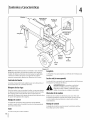
RecordProductinformation
Before setting
up and operating
information
in the provided
MODEL NUMBER
your new equipment,
locate the model plate on the equipment
DIqFllqFllqFllqNIqD
please
and record the
area to the right. You can locate the
model plate by standing behind the unit and looking down at
the hydraulic tank. This information
will be necessary, should
you seek technical
Department,
support
via our web site, Customer
or with a local authorized
................................................................
SERIALNUMBER
Support
DIqFIIqFIIqFIIqFIIqD
service dealer.
CustomerSupport
Please
do NOT return
If you have difficulty
this machine,
the machine
assembling
to the retailer
this product
you can seek help from
Visit us on the web at www.mtdproducts.com
0
Call a Customer
0
Write
Support
Representative
without
or have any questions
the experts.
0
or dealer
Choose
from
at (800) 800-7310
us at MTD LLC • RO. Box 361131 • Cleveland,
first contacting
regarding
the options
the controls,
below:
or (330) 220-4683
OH • 44136-0019
our Customer
operation,
Support
Department.
or maintenance
of
2
ImportantSafeOperationPractices
WARNING:
This symbol
could endanger
all instructions
points out important
the personal
safety and/or
in this manual
with these instructions
before
property
attempting
may result in personal
When you see this symbol.
safety instructions
of yourself
to operate
which,
if not followed,
and others.
this machine.
Read and follow
Failure to comply
injury.
HEED ITS WARNING!
CALIFORNIA
PROPOSITION
65
WARNING: Engine Exhaust, some of its constituents,
and certain vehicle components
contain or emit chemicals known to State of California to cause cancer and birth defects
or other reproductive
harm.
DANGER: This machine
this manual.
operator
was built to be operated
As with any type of power
debris. Failure to observe
serious injury
or death.
Read, understand,
machine
assemble
future
and follow
all instructions
and in the manual(s) before
and operate.
and regular
reference
on the
attempting
Keep this manual
to
replacement
parts.
2.
Be familiar with all controls and their proper operation.
Know how to stop the machine and disengage them
and safe operation
5.
and be trained
practices
by an
10.
Never allow adults to operate
instruction.
this machine
without
proper
11.
logs, never activate the control until the helper is a
minimum
of 10 feet from the machine.
6.
7.
8.
Keep bystanders, pets, and children
the machine while it is in operation.
Never allow anyone
Never transport
at least 20 feet from
to ride on this machine.
cargo on this machine.
during
a pin hole opening
Do not operate
can
machine
hoses, tubing,
or other
Do not adjust
va Ive.
the pressure
or tubing.
system components.
settings of the pump or
Leaks can be detected by passing cardboard or wood,
while wearing protective
gloves and safety glasses, over
area. Look for discoloration
of cardboard
or
If injured by escaping fluid, see a doctor immediately.
Serious infection or reaction can develop if proper medical
treatment
12.
with frayed, kinked,
hoses, fittings,
Stop the engine and relieve hydraulic system
pressure before changing or adjusting fittings,
the suspected
wood.
Many accidents occur when more than one person
operates the machine. Ira helper is assisting in stacking
high fluid pressures
Fluid escaping through
b.
d.
in this manual
and supervised
develop
result in
Do not check for leaks with your hand.
c.
and on the machine
adult.
log splitters
in
hands and feet
could
a.
Never allow children under 16 years of age to operate this
machine. Children 16 and over should read and understand
the instructions
4.
operation.
cracked, or damaged
quickly.
3.
of amputating
safety instructions
Hydraulic
practices
or error on the part of the
penetrate your skin and cause blood poisoning, gangrene,
or death. Give attention to the following instructions
at all
times:
in a safe place for
and for ordering
is capable
the following
9.
to the safe operation
carelessness
can result in serious injury. This machine
and throwing
Training
1.
according
equipment,
is not administered
Keep the operator
immediately.
zone and adjacent
area clear for safe,
secure footing.
13.
If your machine
is equipped
with an internal
combustion
engine and is intended for use near any unimproved
forest,
brush, or grass covered land, the engine exhaust should be
equipped
with a spark arrester. Make sure you comply
applicable
local, state, and federal
firefighting
equipment
with you.
with
codes. Take appropriate
14. Thismachine
should
beused
forsplitting
woodonly,do
notuseitforanyotherpurpose.
15. Follow
theinstructions
inthemanual(s)
provided
withany
attachment(s)
forthismachine.
Preparation
Always wear safety shoes or heavy boots.
2.
Always wear safety glasses or safety goggles
3.
alcohol,
machine
Never allow anyone
proper instruction.
5.
Always operate
6.
when
this machine
5.
Always block wheels to prevent
Operator
Zone
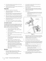
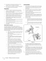
Horizontal
unintended
Always operate this machine
specified in the manual.
7.
Logs should
8.
Use log splitter
from the operator
of
without
with all safety equipment
Operating
Position:
are properly
Stand on the control
in front of the wheel as
shown in Fig. 2-1.
b.
Vertical Operating Position: Stand in front of the
beam and log as shown in Fig. 2-1.
movement,
or vertical
this machine
lever side of the log splitter
before operating.
and lock beam in either the horizontal
the influence
Make sure all controls
for safe operation.
Never wear jewelry or loose clothing that might become
entangled in moving or rotating parts of the machine.
is on a level surface
to operate
adjusted
a.
Make sure machine
while under
drugs, or medication.
4.
this machine.
4.
6.
Do not operate
in place and working.
1.
operating
3.
position.
zone(s)
Horizontal
be cut with square ends prior to splitting.
in daylight
or under
good artificial
light.
SafeHandlingof Gasoline
To avoid personal
in handling
injury
or property
gasoline. Gasoline
vapors are explosive.
damage
is extremely
Serious personal
use extreme
flammable
injury
can occur when
gasoline is spilled on yourself or your clothes which
Wash your skin and change clothes immediately.
a.
Use only an approved
b.
Extinguish
care
and the
can ignite.
gasoline container.
all cigarettes,
cigars, pipes, and other
sources of ignition.
c.
Never fuel machine
d.
Never remove
indoors.
gas cap or add fuel while
the engine
Vertical
is
"
hot or running.
,j)
Figure 2=1
e.
Allow engine to cool at least two minutes
before
7.
refueling.
fl
Never overfill
of filler neck to provide
stabilize a log. Failure to do so, may result in crushed
amputated
fingers, toes, hand, or foot.
space
for fuel expansion.
g.
Replace gasoline
h.
If gasoline is spilled, wipe it off the engine and
equipment and move machine to another area. Wait
five (5) minutes
i.
cap and tighten
before starting
Never store the machine
securely.
or fuel container
Use only your hand to operate
9.
Never attempt
10.
For logs which are not cut square, the least square end and
Allow machine
before
inside
J
the control.
moving
stabilize the log
Place log on the end plate and turn until it leans
When splitting
extra large or uneven
must be stabilized
this machine,
Never leave this machine
position,
Split as follows:
against the beam and is stable.
b.
Before starting
SECTION 2 --
in the vertical
before
a.
to cool at least five (5) minutes
between
review the "Safety
unattended
with the engine
running.
4
When splitting
storing.
Instructions".
Failure to follow these rules may result in
serious injury to the operator or bystanders.
2.
to split more than one log at a time.
end plate.
11.
Operation
1.
the controls.
the longest portion of the log should be placed toward the
beam and wedge, and the square end placed toward the
dryer or other gas appliances.
j.
or
8.
the engine.
where there is an open flame, spark or pilot light
as on a water heater, space heater, furnace, clothes
a log, always place your hands on the sides
of the log, not on the ends, and never use your foot to help
the fuel tank. Fill tank to no more than
1/2 inch below bottom
When loading
IMPORTANT SAFE OPERATION
PRACTICES
12.
with wooden
logs, the log
shims or split wood
the log and end plate or ground.
Always keep fingers away from any cracks that open in
the log while splitting. They can quickly
amputate your fingers.
close and pinch or
13.
Keep your work area clean. Immediately
around
14.
the machine
remove
so you do not stumble
split wood
over it.
Do not change the engine governor settings or overspeed
the engine. The governor controls the maximum safe
operating
Never move this machine
16.
This machine
or public
should
while
the engine
not be towed
road without
checking
is running.
on any street, highway
the existing
federal,
Origin"
is required
Do not tow machine
18.
See Transporting
towing
requirements
Ira "Statement
effective
is
of
in your state, see your local dealer.
17.
proper
of the purchaser.
the Log Splitter
section
in this manual for
once all federal,
system is equipped
meeting
applicable
working
with a spark arrester
local or state laws (if any).
local, or state
order by the operator.
the above is required
be maintained
in
In the State of California
by law (Section 4442 of the California
Public Resources Code). Other states may have similar laws.
Federal laws apply
over 45 mph.
instructions
exhaust
If a spark arrester is used, it should
state, or local vehicle requirements.
Any licensing or
modifications
such as taillights, etc., needed to comply,
the sole responsibility
internal combustion
engine and should not be used
machine isforest-covered,
equipped with brush
an
on ARNING:
or near anyThis
unimproved
covered or grass-covered
land unless the engine's
_k
speed of the engine.
15.
Spark Arrestor
on federal
lands.
A spark arrester for the muffler is available through your
nearest engine authorized service dealer or contact the service
department,
RO. Box 361131 Cleveland,
Ohio 44136-0019.
are met.
Maintenanceand Storage
1.
Stop the engine, disconnect the spark plug and ground
it against the engine before cleaning, or inspecting the
machine.
2.
Stop the engine
and relieve hydraulic
cycling the valve control
several times while engine
is not running;
neutral before repairing or adjusting
or other system components.
3.
To prevent
system pressure by
lever from forward
to reverse
returning
fittings,
to
hoses, tubing,
fires, clean debris and chaff from the engine
and muffler
areas. If the engine
is equipped
with a spark
arrester muffler, clean and inspect it regularly according
manufacturers
instructions.
Replace if damaged.
4.
5.
Periodically
to
check that all nuts and bolts, hose clamps, and
hydraulic
fittings
working
condition.
are tight to be sure equipment
is in safe
Check all safety guards and shields to be sure they are in
the proper position. Never operate with safety guards,
shields, or other protective
features removed.
6.
The pressure relief valve is preset at the factory.
Do not
adjust the valve.
7.
Never attempt to move this machine over hilly or uneven
terrain without a tow vehicle or adequate help.
8.
For your safety, replace all damaged
immediately
with original
or worn parts
equipment
(O.E.M.) parts only. "Use of parts which
original
equipment
performance
9.
specifications
and compromise
Do not alter this machine
as attaching
personal
10.
do not meet the
may lead to improper
safety!"
in any manner, alterations
a rope or extension
adding to the width
manufacturer's
to the control
or height of the wedge
such
handle,
or
may result in
injury.
According to the Consumer Products Safety Commission
(CPSC) and the U.S. Environmental
Protection Agency (EPA),
this product
has an Average UsefulLife
or 130 hours of operation.
Life have the machine
of seven (7) years,
At the end of the Average Useful
inspected
annually
by an authorized
service dealer to ensure that all mechanical and safety
systems are working properly and not worn excessively.
Failure to do so can result in accidents,
injuries
or death.
SECTION 2 --
IMPORTANT SAFE OPERATION
PRACTICES
S
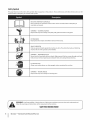
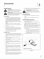
Safety Symbols
This page depicts and describes safety symbols that may appear
machine before attempting
to assemble and operate.
on this product.
Read, understand,
and follow
all instructions
on the
READ THE OPERATOR'S MANUAL(S)
Read, understand,
assemble
and follow
all instructions
in the manual(s) before
attempting
to
and operate
WARNING--
CRUSHING HAZARD
Keep hands away from wedge, end plate, partly split wood
and moving
parts.
BYSTAN DARDS
Keep bystanders,
helpers and children
at least 10 feet away.
SINGLE OPERATOR
Only one person should operate the machine at a time. The adult who loads and holds log
must be the one who operates control
WARNING--
handle.
PRESSURIZED FLUID
Never check for hose leaks with your hands. High pressure fluid can escape through
leak and cause serious injury by puncturing
a pin hole
the skin and causing blood poisoning.
EYE PROTECTION
Always wear safety glasses or safety goggles
WARNING--
follow
Your Responsibility--Restrict
the warnings
and instructions
operating
parts.
the use of this power machine
to persons
in this manual and on the machine.
SAVETHESEINSTRUCTIONS!
6
I
SECTION 2 --
IMPORTANT SAFE OPERATION
this machine.
MOVING WEDGE
Keep hands away from wedge and moving
WARNING:
when
PRACTICES
who read, understand
and
3
Assembly
& Set-Up
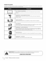
Contents of Carton
One Log Splitter
One Tongue
One Engine Operator's
NOTE:This
Operator's
Manual
Manual
Assembly
One Operator's
Manual
One Tail Light Kit (If equipped)
covers several models.
Log splitter
features may vary by model. Not all features in this manual are
applicable to all log splitter models and the log splitter depicted
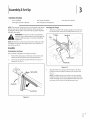
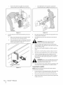
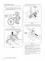
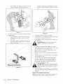
Attaching the Tongue
I.
With the log splitter
still standing
upright,
remove the two
hex bolts and hex nuts from the tank bracket.
may differ from yours.
f
Tongue
See Fig. 3-2.
"
He× Nuts
machine. Some components
are very heavy and will
WARNING!
Use extreme
caution
unpacking
this
require additional
people or
mechanical
handling
equipment.
-NOTE:All
references
log splitter
in this manual to the left or right side of the
are from the operating
position
only. Exceptions,
if
any, will be specified.
Assembly
Attaching the JackStand
The jack stand is shipped
I.
position.
Remove the spring clip and clevis pin, then pivot the jack
stand towards
2.
in the transport
the ground
to the operating
Secure the jack stand in position
position.
Tank Bracket
with the clevis pin and
spring clip. See Fig. 3-I.
f
Figure 3-2
2.
Align the holes in the tongue
NOTE:The
high pressure hose, which
pump
the bottom
tongue
assembly.
of the control
!
Clevis Pin
J
See
runs from the gear
valve, must be above the
See Section 8 (Illustrated
are unsure of which
Figure 3-1
with the holes in the tank
bracket and secure with the hardware just removed.
Fig. 3-2.
Clip
Parts List) if you
hose is the high pressure hose.
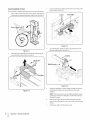
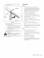
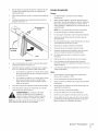
3.
ConnectingCylinderto Beam
The log splitter
I.
is shipped
Pull out the vertical
with the beam in the vertical
beam lock, rotate
beam into the horizontal
Vertical
position
Disconnect
control
position.
the log cradle from the beam on the side of the
valve. See Fig. 3-5.
it back, and pivot the
Screws
until it locks. See Fig. 3-3.
Log CradJ
Beam Lock'
Figure
4.
Figure
2.
Disconnect
the dislodger
Lift and slide the cylinder
into the weld brackets.
3-3
from the beam weld bracket
up to the top of the beam and
See Fig. 3-6.
by
removing the six hex screws. See Fig. 3-4.
Hex
3-5
vlinder
Screws
.............
Weld
He× Screws
J
Figure 3-6
5.
_J
Figure 3-4
Attach the dislodger
it with the previously
brackets.
NOTE:Once
over the wedge assembly and secure
removed hardware to the weld
the six hex screws are tightened,
a slight gap between
This gap is normal.
6.
the dislodger
Reattach the log cradle to the side of the beam with the
control
valve, aligning
the ends of the cradle with the beam
flanges.
7.
8
I
SECTION2--
ASSEMBLY&
SET-UP
there may be
and the weld brackets.
Roll the log splitter
off the bottom
crate.
4.
TailLight installation(If equipped)
The mounting
installation
brackets for the tail light are installed.
sheet included
5.
the
lights and route the harness.
6.
the engine
instructions
Reconnect
following
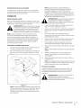
6as and Oil Fill-Up
Service the engine
Disconnect
with gasoline and oil as instructed
manual packed with your log splitter.
carefully.
the spark plug wire and start the engine
the instructions
Use the control handle to engage the wedge
extended position. Then retract the wedge.
8.
If neccessary,
or while
the engine
automatic
splitter
Gasoline can be added
is in either the horizontal
there are less obstructions
position.
is hot or running.
refill the tank as specified
or vertical
position.
However,
2.
wedge
Remove the vented
is located
front of the engine
reservoir
dipstick,
which
TM
AW-32 Hydraulic
9.
Extend and retract
the wedge
remove any trapped
bleeding").
will
12 complete
cycles to
air in the system (the system is "self-
Refill the reservoir
within
the range marked on the dipstick.
NOTE: Some fluid
may overflow
from the vent plug as
the system builds heat and the fluid
balanced level.
expands
and seeks a
in
on top of the reservoir tank. See Fig. 3-7.
Tire Pressure
log splitter
is filled to the proper operating
level
The max recommended
with Shell Tellus ® 32 Hydraulic
Fluid.
not, under any circumstances, exceed the manufacturer's
recommended
psi. Maintain equal pressure on all tires.
However, you MUST check the fluid level before
If not filled, proceed with the following
steps:
WARNING!
Much of the original
drawn into the cylinder
refill the reservoir
hydraulic
Check the fluid
overfill.
fluid
operating.
has been
and hoses. Make certain to
to prevent
damage
Oil
Fluid.
from the manufacturer
NOTE:The
3.
Dexron ® III / Mercon ®
fluid, Pro-Mix
warranty.
10.
Lubricate the beam area (where the splitting
slide) with engine oil. Do not use grease.
on the dipstick.
NOTE: Failure to refill the tank will void the splitter's
is in the vertical
Preparing the Log Splitter
1.
fluids include
transmission
Tellus ® 32 Hydraulic
to the engine when the log
when the splitter
to the farthest
or a 10 Weight AW hydraulic oil. It is not recommended
that
fluids be mixed, so to top off the reservoir tank use Shell
NOTE:Your log splitter may be shipped with motor oil in the
engine. You MUST check the oil level before operating.
Be careful
not to overfill.
Section.
Read the
gasoline. Gasoline is extremely flammable
and the
WARNING!
Use extreme
handling
vapors
are explosive.
Nevercare
fuel when
the machine
indoors
in the Operation
7.
in
by pulling
as far as it will go. Repeat approximately
NOTE:Approved
_
it until the
the spark plug and prime the pump
the recoil starter
10 times.
Set-Up
securely, tightening
top of the threads are flush with the top of the pipe.
Refer to the
with the tail light kit to mount
Replace the vented dipstick
i_li
operating
pressure is 30 psi. Do
may cause the tire/rim assembly to burst with force
WARNING!
Excessive
pressure
sufficient to cause
serious
injury. when seating beads
to the
pump.
level using the dipstick.
See Fig. 3-7. Do not
f
Reservoir
Tank
\
\
Figure 3-7
SECTION
2 --
ASSEMBLY& SET-UP
9
4
Controls
and Features
Cylinder_
,g Dislodger
Control Handle
Horizontal
Beam Lock
Assembly
Vertical
Beam
Lock
Log
Cradle
Light
Figure 4=1
NOTE:This Operator's
Manual
covers several models.
Log splitter
TailLight (if equipped)
features may vary by model. Not all features in this manual are
applicable to all log splitter models and the log splitter depicted
The tail light's are located
may differ from yours.
transportation
on the back of the frame for
and towing
purposes.
EngineControls
See the Engine Operator's Manual
of the controls on the engine.
for the location
check the local,
andfaster
federalthanrequirements
WARNING!
Do state,
not tow
45mph and
before towing on any public road.
and function
Log Dislodger
BeamLocks
The log dislodger
These two locks are used to secure the beam in the horizontal
vertical
position.
The vertical
filter. The horizontal
latch bracket.
beam lock is located
beam lock is located
next to the oil
The Control
split wood.
splitting
split wood
large diameter
Forward,
Handle is used to move the wedge
up and down to
Neutral and
Section for instructions.
Tongue
Wedge
The wedge
to remove any partially
Control Handle
handle has three positions;
Reverse. See the Operation
is designed
from the wedge. This may occur while
wood or freshly cut wood.
on the beam support
Control Handle
The control
or
is used to split the wood.
The tongue
transportation.
is used to attach to a towing
vehicle for
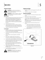
Operation
Starting the Engine
WARNING!
Stopping the Engine
Read, understand
instructions
and warnings
this manual
before operating.
WARNING!
and follow
on the machine
all
Wear leather work gloves, safety shoes,
and safety glasses when
Ensure safe footing.
operating
1.
Move the throttle control (if equipped) to the STOPor OFF
position.
2.
Turn off the engine switch, if so equipped.
and in
Usingthe Log Splitter
a log splitter.
Place the log splitter on dry level ground and shut offthe
engine.
Before EachUse
2.
Block the front and back of both wheels.
1.
3.
Place the beam in either the horizontal or vertical position
and lock in place with the appropriate locking rod.
With the spark plug wire disconnected, remove the dipstick
and check the hydraulic fluid level. Refill if necessary.
Approved fluids include Shell Tellus®32 Hydraulic Fluid,
Dexron ®III/ Mercon ®automatic transmission fluid,
Pro-Select AW-32 Hydraulic Oil or 10WAW-ISOviscosity
grade 32 hydraulic oil. Check the engine oil level. Refill if
necessary.
NOTE:Take extra care when raising and lowering the beam
as it is fairly heavy. Be sure to keep hands away from any
possible pinch points.
TM
2.
Fill up the gasoline if necessary.
3.
Lubricate the beam area where the splitting wedge will
slide with engine oil. Do not use grease to lubricate. Make
sure to lubricate both the front and back of the beam face.
4.
Attach the spark plug wire to the spark plug.
Starting Engine
1.
4_
To place the beam in the Vertical Position proceed as
follows:
a.
Pull the horizontal beam lock out to release the
beam and pivot the beam to the vertical position.
b.
To lock the beam in the vertical position, pull out
on the vertical beam lock and rotate it to secure the
beam. See Fig. 5-1.
f
Attach the spark plug wire to the spark plug. Make certain
the metal cap on the end of the spark plug wire is fastened
securely over the metal tip of the spark plug.
2.
Turn the fuel valve or the engine switch (if equipped) to the
ON position.
3.
Move the choke control (if equipped) to the CHOKE
position.
4.
If the engine is equipped with a primer, follow the
instructions in the Engine Operator's Manual to prime it.
5.
Turn the throttle control (if equipped) to the FASTposition.
6.
Grasp the starter handle and pull the rope out slowly until
the engine reaches the start of the compression cycle (the
rope will pull slightly harder at this point).
7.
Pull the rope with a rapid, full arm stroke. Keep a firm
grip on the starter handle and let the rope rewind slowly.
Repeat until the engine cranks.
8.
After the engine starts, move the choke control (if
equipped) to the OFF position. Place the throttle lever at
the desired speed.
i
i
Figure S-1
In cold weather, run the wedge up or down the beam 6 to 8
times to circulate the hydraulic fluid.
WARNING!
When starting
a warm engine,
the
muffler and surrounding
areas are hot and can
cause a burn. Do not touch these areas.
11
c.
Stand in front of the log splitter
control
handle and to stabilize
to operate
the
c.
the log. See Fig. 5-2.
Stand behind the reservoir
control
To place the beam in the Horizontal Position proceed as
follows:
a.
Pull the vertical
beam lock out and rotate
Pivot the beam to the horizontal
b.
The horizontal
the
the log. See Fig. 5-4.
Figure 5-4
Figure 5-2
4.
tank to operate
handle and to stabilize
it down.
4.
in the direction
5.
position.
beam lock is self-locking.
Place the log against
To stabilize
the log.
the end plate and only split the wood
of the grain.
the log, place your hand only on the sides of
The spring
loaded lock will snap into place when the beam is
lowered
into position.
See Fig. 5-3.
_
6.
ARNING!
Never placea hand on the end
between the log and the splitting wedge.
Only one adult should stabilize the log and operate the
control handle, so the operator has full control over the log
and the splitting
7.
Move the control
wood.
8.
Release the control
9.
Move the control
10.
To remove
control
handle to stop the wedge
movement.
handle BACK or UP to return the wedge.
partially
split wood
from wedge,
to allow
split wood
move the
until the wedge
portion
to contact
is
the
theARNING!
wedge with
your remove
hands. partially
Fingers may
Never
split become
wood from
trapped between the split wood.
_
11.
handle FORWARD or DOWN to split the
handle to the REVERSEposition
fully retracted
log dislodger.
Horizontal Beam Lock
wedge.
Once removed
the wood
from the wedge
from the opposite
with the log dislodger,
end or in another
split
location.
Transportingthe LogSplitter
Figure 5-3
NOTE:Always
transporting
1.
turn the fuel valve to the OFF position
Lower the beam to its horizontal
position.
beam is locked securely with the horizontal
12
I
SECTION
5--
OPERATION
before
the log splitter.
Make certain the
beam lock.
2.
Remove the spring clip and clevis pin from the jack stand.
3.
Support
the tongue
tongue.
See Fig. 5-5.
and pivot
the jack stand up against the
4.
Secure with the spring clip and clevis pin previously
removed.
OperatingTips
See Fig. 5-5.
Always:
1.
Use clean fluid and check the fluid
2.
Use an approved
hydraulic
Shell Tellus ®32 Hydraulic
level regularly.
fluid. Approved
fluids include
Fluid, Dexron ® III / Mercon ®
automatic transmission
fluid, Pro-Select TM AW-32 Hydraulic
Oil or 10WAW-ISO viscosity grade 32 hydraulic oil.
NOTE: It is not recommended
that fluids
3.
Use a filter (clean or replace
4.
Use a breather
5.
Make sure the pump is mounted
6.
Use a flexible
regularly).
cap on the fluid
"spider"
be mixed.
reservoir.
and aligned
type coupling
properly.
between
the engine
and pump drive shafts.
7.
Keep the hoses clear and unblocked.
8.
Bleed the air out of the hoses before
9.
Flush and clean the hydraulic
operating.
system before
restarting
after
servicing.
Figure
5.
Attach
the coupler
towing
vehicle;
a.
If the coupler
Ifthe
coupler
adjustment
Use "pipe
11.
Allow time for the engine
wood.
12.
Prime the pump
hitch to a class I or higher 2" ball on a
hitch does not fit on the ball: Turn the
dope" on all hydraulic
fittings.
to warm-up
before
splitting
nut one turn clockwise.
the initial
start-up
by turning
over
(if not already
13.
Split the wood
along the grain (lengthwise)
only.
Then recheck
Never:
Connect
the safety chains to the towing
7.
Plug in the tail lights, if equipped,
vehicle.
to the tail light connector
vehicle.
check the local,
andfaster
federalthanrequirements
WARNING!
Do state,
not tow
45mph and
before towing on any public road.
backing
before
with the spark plug disconnected
done at factory).
hitch is too loose on the ball: Turn the
6.
NOTE: Use caution when
vehicle is recommended.
the engine
nut one turn counter-clockwise.
and adjust accordingly.
on the towing
10.
latch securely.
adjustment
b.
5-5
up. Using a spotter
outside
1.
Use when
fluid is below 20° F or above 150° F.
2.
Use a solid engine/pump
3.
Operate through
4.
Attempt
to adjust
coupling.
relief valve for more than 5 seconds.
unloading
or relief valve settings
without
pressure gauges.
the
5.
Operate with air in hydraulic
system.
6.
Use Teflon tape on hydraulic
fittings.
7.
Attempt
8.
Attempt to remove partially split wood from the wedge
with your hands. Fully retract wedge to dislodge wood
to cut wood
across the grain.
with log dislodger.
SECTION
5 --
OPERATION
13
Maintenance& Adjustments
WARNING!
first stopping
Do not make any adjustments
without
the engine, disconnecting
the spark
plug wire and grounding
it against the engine.
Always wear safety glasses during operation or
while
performing
any adjustments
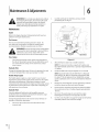
2.
Carefully
penetrating
unthread
the inlet filter and clean it with
oil. See Fig. 6-1.
(_
or repairs.
Maintenance
i
Engine
Refer to the Engine Operator's
splitter
for all engine
Manual
packed with your log
maintenance.
Tire Pressure
The max recommended
operating
not, under any circumstances,
recommended
psi. Maintain
pressure is 30 psi. Do
exceed the manufacturer's
equal pressure on all tires.
WARNING! Excessive pressure when seating beads
may cause the tire/rim assembly to burst with force
sufficient to cause serious injury. Refer to the
sidewall of the tire for the recommended pressure.
Suction
Hose
HoseClamps
J
Check the hose clamps on the suction
the side of the pump)
hose (attached
to ensure they are tight
to
before each
Figure 64
3.
use. Check the hose clamps on the return hose at least
once a season.
NOTE:The
Change the hydraulic
filter every 50 hours of operation.
a 10 micron
filter. Order part number
hydraulic
Use only
4_
723-0405.
pump
the pump
coupler
will experience
is a nylon "spider"
insert, located
fails completely,
grade 32 hydraulic
mixed.
5.
6.
HydraulicFluid
specified
on the dipstick
level in the log splitter
reservoir
the fluid level within
the range
7.
Disconnect
Disconnect the suction
reservoir tank.
every 100 hours of
hose from the bottom
of the
Reconnect
following
at all times.
Change the hydraulic fluid in the reservoir
operation. Follow the steps below:
1.
fluids include
of approximately
Do not overfill.
Shell Tellus ®32 Hydraulic
transmission
fluid,
Oil or IOWAW-ISO viscosity
oil. It is not recommended
Replace the vented dipstick
that fluids be
securely, tightening
the spark plug and prime the pump
the recoil starter
10 times.
tank before each use. Maintain
of 3 gallons and
it until the
top of the threads are flush with top of the pipe.
you
a loss of power.
fluid
level using the dipstick.
Pro-Select T_AW-32 Hydraulic
and the engine shaft. Over time, the coupler
service dealer. If the coupler
Check the hydraulic
tank has a capacity
container.
system has a capacity
Fluid, Dexron ® III / Mercon ®automatic
will harden and deteriorate.
If you detect vibration
or noise
coming from the area between the engine and the pump contact
an authorized
Check the fluid
NOTE:Approved
Flexible Pump Coupler
between
reservoir
the entire hydraulic
4.7 gallons.
Hydraulic Filter
The flexible
Allow the fluid to drain into a suitable
8.
by pulling
as far as it will go. Repeat approximately
the spark plug wire and start the engine
the instructions
in the Operation
Use the control handle to engage the wedge
extended position. Then retract the wedge.
Section.
to the farthest
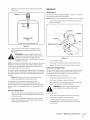
9.
Refill the reservoir
within
range marked
on the dipstick.
See Fig. 6-2.
Adjustments
Gib Adjustment
Periodically
remove and replace the gibs --
the wedge
assembly
NOTE:The
gibs may be rotated
I.
spacers --
between
and the back plate.
and/or
turned
over for even wear.
Loosen the lock nuts under each back plate and slide the
gibs out. See Fig. 6-3.
f
Nut
Hydraulic Fluid
Only
Adjustment Bolt*
Figure 6-2
10.
Extend and retract
remove
trapped
the wedge
12 complete
cycles to
air in the system (the system is "self-
bleeding").
drawn into the cylinder and hoses. Make certain to
WARNING!
refill the reservoir
Much toofprevent
the original
damage
fluid tohas
the been
_
hydraulic
pump.
log splitter's
Figure 6-3
Failure to refill the tank will void the
warranty.
2.
Turn or replace the gibs.
3.
Reassemble
builds heat and the fluid expands and seeks a balanced level.
Do not operate the log splitter without the proper amount of
transmission fluid in the reservoir tank.
4.
Readjust the bolts on the side of the wedge assembly.
Maintain
Use the control
NOTE: Some fluid
the fluid
may overflow
level within
at all times. When checking
the dipstick
the pipe.
from the vent plug as the system
the range specified
until the top of the threads
dispose of any used hydraulic
engine oil at approved
components.
are flush with the top of
Raisingand Loweringthe Beam
thin the fluid.
in the fluid
Flushing
recycling
centers
fluid and
only.
the hydraulic
Place the log splitter
up and down the beam
fluid, which
will warm and
on a firm, level surface.
operation:
I.
Pull out the horizontal
2.
Pivot beam lock down to release the beam.
beam lock on the tongue.
3.
Move the beam to the vertical
may damage the hydraulic
the reservoir tank and hoses with
top, sides and bottom
of the beam and where it
Make certain to readjust
wedge
the adjustment
with engine
Secure it with the
vertical position when splitting heavy logs.
WARNING!
Always use the log splitter in the
Beamand Splitting Wedge
comes into contact with the splitting
oil before each use.
position.
beam lock on the reservoir tank assembly.
kerosene whenever service is performed
on the tank, hydraulic
pump or valve is recommended.
Contact an authorized service
dealer.
Lubricate
handle to run the wedge
6-8 times to circulate
To raise the beam for vertical
NOTE:Always
Contaminants
on the dipstick
the fluid, always make sure to tighten
the back plate and secure it with lock nuts.
To lower the beam:
1.
Pull out the vertical
beam lock on the reservoir
tank.
2.
Pivot beam lock down to release the beam.
3.
Carefully pull back on the beam and lower it to the
horizontal
position. The horizontal beam lock will lock
bolts so that the
wedge moves freely, but no excess space exists between
the wedge plate and the beam.
automatically.
SECTION 6 --
MAINTENANCE
& ADJUSTMENTS
15
WedgeAssembly
As normal
wear occurs and there
the wedge
and beam, adjust the bolts on the side of the wedge
assembly
beam.
to eliminate
is excessive "play"
excess space between
the wedge
1.
Loosen the jam nuts on the two adjustment
side of the wedge. See Fig. 6-3.
2.
Turn the adjustment
3.
bolts on the
1-1/2turns) until the wedge
will slide on the beam.
Re-tighten
wedge
and the
bolts in until snug and then back
them off slowly (approximately
assembly
between
the jam nuts securely against the side of the
to secure the adjustment
bolts in this position.
Off-SeasonStorage
If the log splitter will not be used for more than 30 days, prepare
it for storage as follows:
i_
the fuel tank inside of building where fumes may
WARNING!
the machine
fuel in
reach an openNever
flame store
or spark,
or where with
ignition
sources are present
heaters, furnaces,
motors, etc.
1.
Clean the log splitter
NOTE:The
to the bearings
Wipe the machine
especially
3.
thoroughly.
is not recommended.
result in a shortened
2.
dryers, stoves, electric
use of pressure washers or a garden
clean the splitter
damage
such as hot water and space
clothes
or the engine.
hose to
They may cause
The use of water will
life and reduce serviceability.
with an oiled
on the wedge
rag to prevent
rust,
and the beam.
Drain the fuel tank. Always drain the fuel into an approved
container outdoors and away from open flames. Be sure
that the engine is cool before draining the fuel. Do not
smoke while
4.
the fuel.
Start the engine and let it run until the fuel lines and
carburetor
5.
handling
are empty.
Remove the spark plug. Holding
a rag over the cylinder
hole, pour approximately
1/2-ounce (approximately
one
tablespoon) of engine oil into the cylinder and crank slowly
to distribute the oil.
6.
Replace the spark plug.
7.
Do not store gasoline from
8.
Replace your gasoline can if it starts to rust. Rust and/or
in the gasoline will cause problems.
9.
Store the log splitter in a clean, dry area. Do not store it
next to corrosive materials, such as fertilizer.
one season to another.
NOTE: If storing in an unventilated
be certain to rustproof
light oil or silicone.
SECTION 6--
or metal storage shed,
the equipment
MAINTENANCE
dirt
by coating
& ADJUSTMENTS
it with a
17
7
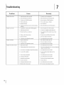
Troubleshooting
Problem
Engine fails to start
Cause
1.
Remedy
Spark plug wire disconnected.
1. Connect w_re to spark plug.
2. Fuel tank empty or stale fuel.
2. Fill tank with clean, fresh gasoline.
3. Choke not in CHOKE position.
3. Move choke to CHOKE position.
4. Faulty spark plug.
4. Clean, adjust gap, or replace.
5. Blocked fuel line.
5. Clean fuel line.
6. Throttle
6. Move throttle
control lever not in correct starting
lever to FAST position.
position.
Engine runs erratic
1,
Log Splitter
running
with CHOKE applied.
1. Move choke lever to OFF position.
2. Spark plug wire loose.
2. Connect and tighten
3. Blocked fuel line or stale fuel.
3. Clean fuel line; fill tank with clean, fresh
spark plug wire.
gasoline.
4. Water or dirt in fuel system.
4. Drain fuel tank. Refill with fresh fuel.
5. Dirty air cleaner.
5. Clean or replace air cleaner.
6. Carburetor
Engine Overheats
1,
notadjusted
properly.
6. See authorized
Engine oil level low.
1. Fill crankcase with proper oil.
2. Dirty air cleaner.
3. Carburetor
Cylinder
rod will not move
2. Clean or replace air cleaner.
not adjusted
properly.
1. Broken drive shaft.
2. Shipping
plugs left in hydraulic
hoses.
3. See authorized
service dealer.
1. See authorized
service dealer.
2. Disconnect
hydraulic hoses, remove shipping
plugs, reconnect
3,
service dealer.
Set screws in coupling
not adjusted
4. Loose shaft coupling.
properly.
3. See authorized
hoses.
service dealer.
4. Correct engine/pump
alignment
necessary.
5. Gear sections damaged.
5. See authorized
service dealer.
6. Damaged
relief valve.
6. See authorized
service dealer.
7. Hydraulic
lines blocked.
7. Flush and clean hydraulic system.
8. Incorrect oil level.
9. Damaged
directional
10. Blocked directional
8. Check oil level.
valve.
valve.
9. See authorized
service dealer.
10. Flush and clean hydraulic system
as
Problem
Slow cylinder
Cause
shaft speed
while extending
retracting
and
2. Excessive pump inlet vacuum.
2. Make certain pump inlet hoses are clear and
unblocked-use
short, large diameter inlet
hoses.
3. SIowengine
3.
speed.
relief valve.
7. Directional
8. Internally
will
slowly
See authorized
service dealer.
4. See authorized
service dealer.
5. Check oil level.
oil level.
6. Contaminated
not split or wood splits too
service dealer.
1,
5. incorrect
Engine runs but wood
See authorized
1. Gear sections damaged.
4. Damaged
Leaking Cylinder
Remedy
oil
6. Drain oil, clean reservoir and refill.
valve leaking internally.
damaged
cylinder.
Z
Seeauthorized service dealer.
8. Seeauthorized service dealer
1. Broken seals.
1. See authorized
service dealer.
2. Scored cylinder.
2. See authorized
service dealer.
1. Small gear section damaged.
1. See authorized
service dealer.
2. Pump check valve leaking.
2. See authorized
service dealer.
3. Excessive pump inlet vacuum.
3. Make certain pump inlet hoses are clear and
unblocked.
4. Incorrect oil level.
4. Check oil level.
5. Contaminated
5. Drain oil, clean reservoirand
6. Directional
oil.
valve leaking internally.
7. Overloaded
cylinder.
refill.
6. See authorized
service dealer.
7. Do not attempt
to split wood against the
grain.
8. Internally
Engine stalls during
splitting
damaged
cylinder.
1. Low horsepower/weak
2. Overloaded
engine.
cylinder.
8. See authorized
service dealer.
1. See authorized
service dealer.
2. Do not attempt
to split wood against the
grain or see authorized
Engine will not turn or stalls
under low load conditions
1. Engine/pump
misalignment.
as necessary.
2. Frozen or seized pump.
2. See authorized
service dealer.
3. Low horsepower/weakengine.
3. See authorized
service dealer.
4. Hydraulic
4. Flush and clean hydraulic system.
lines blocked.
5. Blocked directional
Leaking pump shaft seal
1. Correct alignment
service dealer.
valve.
5. Flush and clean hydraulic system.
1. Broken drive shaft.
1. See authorized
2. Engine/pump
2. Correct alignment
misalignment.
service dealer.
as necessary.
3. Gear sections damaged.
3. See authorized
service dealer.
4. Poorly positioned
4. See authorized
service dealer.
5. Plugged
shaft seal.
oil breather.
5. Make certain reservoir is properly
vented.
SECTION
7 -- TROUBLESHOOTING
19
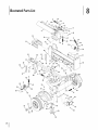
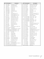
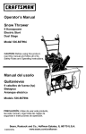
illustratedPartsList
22
\
36
\
3X
45
38
\
37
56
69
72\
75_
76
73
Refl
Part Number
I
711-04585
2
913-04036
3
914-0111
4
918-04533
918-04534
918-0481A
Description
Ref
Part
Clevis Pin, .25 x 1.00
36
681-04030
Hitch Coupling
Handle Valve Link
37
710-0521
Hex Screw, 3/8-16x 3.00
Cotter Pin,
38
710-3085
Hex Screw, 3/86x 3.50
Valve (510)
39
911-0813
Clevis Pin, %0 x 2.5
Valve (550)
40
712-04065
Flange Lock Nut, 3/8-16
3/322 X 1.0
Number
Description
Assembly
Valve (570)
41
713-0433A
Tow Chain
5
918-0769A
Hydraulic
42
915-0120
Spirol Pin, %0 x 1.00
6
720-04088
Grip
43
732-0194
Spring Pin
7
727-04166
Hydraulic
44
932-3127
Compression
936-0185
Flat Washer, .375 x .738 x .063
Cylinder
Hose, 3/4-16
Spring, .66 x 1.8
8
737-0153
Hydro Fitting, 90 x 3/4x .75
45
9
737-0192
Hydro Fitting, 90 x 3/4x 1/2
46
747-1261
Tongue
Latch Rod
10
737-0238
Nipple
47
781-1045-0662
Tongue
Latch -- Gray
781-1045-0638
Tongue
Latch -- Red
Fitting, 1/2x 1.89
11
747-04539
Hydraulic
12
710-0459A
Hex Screw, 3/8-24 x 1.50
48
781-0789-0637
Jack Stand
13
710-1018
Hex Screw, 1/2-20x 2.75
49
781-0788-0662
Tongue Tube -- Gray
781-0788-0638
Tongue Tube --Red
14
710-1806
15
712-0711
16
712-3022
17
912-3058
18
719-0550A
19
781-0351
Adjust
2O
781-0790-0637
21
710-0654A
22
781-I048A-0662
Dislodger
781-I048A-0638
Dislodger
Valve Control
Hex Screw, 1/2-13x 3.25
Jam Nut, 3/8-24
50
726-0214
Push Cap, %
Hex Lock Nut, 1/2-13
51
732-0583
Compression
Hex Lock Nut, 1/2-20
52
936-0116
Flat Washer, .635 x .93 x .06
Wedge
53
781-0690
Lock Rod
54
981-04040A-0637
Frame Assembly
Back Plate
55
710-3085
Hex Screw, 3/8-16x 3.50
Self-Tapping
56
712-04065
Flange Lock Nut, 3/8-16
Bracket -- Gray
57
710-0502A
Self-Tapping
Bracket -- Red
58
736-3010
Flat Washer, .407 x .812 x .135
737-0348A
Vented Dipstick
Gibs, .625 x .625 x 2.00
Screw, 3/8-16-1.000
Spring, .625 x 4.0
Screw, 3/8-16x 1.250
23
723-0405
Oil Filter
59
24
726-0132
Hose Clamp
60
710-0376
Hex Screw, %6-18 x 1.00
25
727-0443
Return Hose
61
710-3056
Hex Screw, %6-18 x 3.25
712-04063
Flange Lock Nut, sA6-18
26
737-0316
Filter Housing
62
27
737-0312
Adapter,
63
918-04127
Gear Pump
28
781-0526A
Hose Guard (510/570)
64
719-0353
Coupling
29
781-0538A
Hose Guard (510/570)
65
917-0891
Flex Coupling
30
711-1587
Clevis Pin, .625 x 4.0
710-1842
Set Screw, 1/4-20x .38
31
914-0470
Cotter Pin, 1/8x 1.25
914-0122
Square Key, %6 x .75
32
681-04071A-0637
Beam Assembly
718-04392
Coupling,
.500
33
710-04484
Hex Washer Screw, %6-18 x .750
718-04395
Coupling,
.875
34
781-04179-0637
Log Tray Bracket
735-04103
Spider Bushing
35
781-04180-0637
Log Tray Bracket
727-04130
Inlet Hose
3/4-14
66
SECTION12
--
Shield
ILLUSTRATED PARTS LIST
21
Refl
Part
67
727-0502
Rubber Hydro Hose
68
737-0329
Hydraulic Fitting, 45 x 3/4x 3A
69
737-04093
Inlet Filter
70
781-0097-0637
RearCoupling Support Bracket
71
710-0602
Hex Washer Screw, sA_-18x 1.000
72
710-0650
Hex Washer Screw, sA_-18x .875
73
712-04063
Flange Lock Nut, sA_-I8
74
731-2496A
Fender (Black, 510/570)
731-2499A
Fender (Red, 550)
Number
Description
75
736-0371
Flat Washer, .343 x .880 x .062
76
634-0186
Complete Wheel Assembly
934-0180-0662
Wheel/Rim Assembly
921-0168
Dust Seal
m
941-0987
Roller Bearing
77
712-0359
Slotted
78
714-0162
Cotter Pin, %2 x 1.25
79
914-0474
Hub Cap
8O
936-0351
Flat Washer, .760 x 1.50 x .030
81
625-0062
Light Assembly
82
681-0164-0637
LH Light Bracket (570)
83
912-3008
Jam Nut, 3/8-16 (570)
84
712-04063
Flange Lock Nut, sA6-18 (570)
85
781-1027A-0637
RH Light Bracket (570)
Nut, 3/4-16
Kit (570)
9
MANUFACTURER'S
LiMiTED WARRANTY
The limited warranty set forth below is given by MTD LLC with
respect to new merchandise purchased and used in the United States
and/or its territories and possessions, and by MTD Products Limited
with respect to new merchandise purchased and used in Canadaand/
or its territories and possessions (either entity respectively, "MTD").
"MTD" warrants this product (excluding its Normal Wear Parts and
Attachments as described below) against defects in material and
workmanship for a period of two (2) years commencing on the date
of original purchase and will, at its option, repair or replace, free of
charge, any part found to be defective in materials or workmanship.
This limited warranty shall only apply if this product has been
operated and maintained in accordance with the Operator's Manual
furnished with the product, and has not been subject to misuse,
abuse, commercial use, neglect, accident, improper maintenance,
alteration, vandalism, theft, fire, water, or damage because of other
peril or natural disaster. Damage resulting from the installation or use
of any part, accessory or attachment not approved by MTD for use
with the product(s) covered by this manual will void your warranty as
to any resulting damage.
Normal Wear Parts are warranted to be free from defects in material
and workmanship for a period of thirty (30) days from the date of
purchase. Normal wear parts include, but are not limited to items
such as: batteries, belts, blades, blade adapters, tines, grass bags,
wheels, rider deck wheels, seats, snow thrower skid shoes, friction
wheels, shave plates, auger spiral rubber and tires.
Attachments-- MTD warrants attachments for this product against
defects in material and workmanship for a period of one (1) year,
commencing on the date of the attachment's original purchase or
lease. Attachments include, but are not limited to items such as:
grass collectors and mulch kits.
HOWTO OBTAINSERVICE:Warranty service is available, WITH
PROOFOF PURCHASE,through your local authorized service dealer.
To locate the dealer in your area:
In the U.S.A.
Check your Yellow Pages, or contact MTD LLC at RO. Box 361131,
Cleveland, Ohio 44136-0019, or call 1-800-800-7310, 1-330-2204683 or log on to our Web site at www.mtdproducts.com.
In Canada
Contact MTD Products Limited, Kitchener, ON N2G4J1, or call 1-800668-1238 or log on to our Web site at www.mtdcanada.com.
This limited warranty does not provide coverage in the following
cases:
a. The engine or component parts thereof. These items may carry a
separate manufacturer's warranty. Referto applicable manufacturer's warranty for terms and conditions.
b. Log splitter pumps, valves, and cylinders havea separate oneyear warranty.
FOR
c. Routine maintenance items such as lubricants, filters, blade
sharpening, tune-ups, brake adjustments, clutch adjustments,
deck adjustments, and normal deterioration of the exterior finish
due to use or exposure.
d. Service completed by someone other than an authorized service
dealer.
e. MTD does not extend any warranty for products sold or exported
outside of the United States and/or Canada, and their respective
possessions and territories, except those sold through MTD's
authorized channels of export distribution.
f. Replacement parts that are not genuine MTD parts.
g. Transportation charges and service calls.
h. MTD does not warrant this product for commercial use.
No implied warranty, including any implied warranty of
merchantability of fitness for a particular purpose, applies after
the applicable period of express written warranty above as to the
parts as identified. No other express warranty, whether written or
oral, except as mentioned above, given by any person or entity,
including a dealer or retailer, with respect to any product, shall
bind MTD. Duringthe period of the warranty, the exclusive remedy
is repair or replacement of the product as set forth above.
The provisions as set forth in this warranty provide the sole and
exclusive remedy arising from the sale. MTD shall not be liable
for incidental or consequential loss or damage including, without
limitation, expenses incurred for substitute or replacement lawn
care services or for rental expenses to temporarily replace a
warranted product.
Some states do not allow the exclusion or limitation of incidental
or consequential damages, or limitations on how long an implied
warranty lasts, so the above exclusions or limitations may not apply
to you.
In no event shall recovery of any kind be greater than the amount of
the purchase price of the product sold. Alteration of safety features of
the product shall void this warranty. You assume the risk and liability
for loss, damage, or injury to you and your property and/or to others
and their property arising out of the misuse or inability to use the
product.
This limited warranty shall not extend to anyone other than the
original purchaser or to the person for whom it was purchased as a
gift.
HOWSTATELAW RELATESTO THIS WARRANTY: This limited
warranty gives you specific legal rights, and you may also have other
rights which vary from state to state.
IMPORTANT: Owner must present Original Proof of Purchase to
obtain warranty coverage.
MTD LLC, P.O. BOX 361131 CLEVELAND, OHiO 44136=0019; Phone: 1=800=800=7310, 1=330=220=4683
MTD Canada Limited = KITCHENER, ON N2G 4J1; Phone 1=800=668=1238
GDOC-lO0015 REV. B
Nledidasimportantesdeseguridad.Configuraci6n.Funcionamiento,Nlantenimiento. Servicio.Soluci6ndeproblemas.Garantia
MANUALDELOPERADOR
M,_quina rornpe troncos m Moclelo de la serie 510 a tray, s de 570
MTD LLC, P.O. BOX 361131 CLEVELAND, OHiO 44136-0019
Impresoen EstadosUnidosdeAmdrica
FormularioNo.769-04973
(27 de mayo,2009)
A!propietario
1
Gracias
Gracias por comprar una m_quina rompetroncos
fabricada
pot MTD LLC. El mismo ha sido diseflado cuidadosamente
para brindar excelente rendimiento
si se Io opera y mantiene
correctamente.
a todos los modelos.
MTD LLC se reserva el derecho
a modificar
Por favor lea todo este manual antes de operar el equipo.
Le indica c6mo configurar, operar y mantener la m_quina
con seguridad y f_cilmente. Por favor asegOrese de seguir
cuidadosamente yen todo momento las pr_cticas de seguridad
recomendadas y de hac_rselas seguir a cualquier otra persona
que opere la m_quina. En caso de no hacerlo podrian producirse
lesiones personales o daflos materiales.
Si tiene algun problema o duda respecto a la m_quina, Ilame a un
distribuidor
de servicio MTD autorizado o p6ngase en contacto
directamente
con nosotros. Los numeros de tel6fono, direcci6n
las especificaciones
de los productos, los diseffos y el equipo
est_ndar sin previo aviso y sin generar responsabilidad
pot
obligaciones
de ning0n tipo.
Toda la informaci6n contenida en este manual hace referencia
a la m_s reciente informaci6n de producto disponible en el
momento de la impresi6n. Revise el manual frecuentemente
para familiarizarse con la m_quina, sus caracteristicas y
funcionamiento. Por favor tenga en cuenta que este Manual
del Operador puede cubrir una gama de especificaciones de
productos de diferentes modelos. Las caracteristicas y funciones
incluidas y/o ilustradas en este manual pueden no ser aplicables
del sitio web y direcci6n postal de Asistencia al Cliente de MTD
se encuentran en esta p_gina. Queremos garantizar su entera
satisfacci6n en todo momento.
En este manual, las referencias al lado derecho o izquierdo de la
m_quina se observan desde la posici6n del operador.
El fabricante del motor esel responsable de todas las
cuestiones relacionadas con el rendimiento, potencia de salida,
especificaciones, garantia y mantenimiento del motor. Para
obtener mayor informaci6n consulte el Manual del Propietario /
Operador entregado por el fabricante del motor, que se envia, en
un paquete por separado, junto con su m_quina.
indice
Medidas
importantes
de seguridad
Montaje
y Conffguraci6n
......................
3
Mantenimiento
........................................
7
Controles y Caractefisticas
....................................
Funcionamiento
.....................................................
10
11
Registro de informaci6nde producto
Antes de configura r y operar su equipo nuevo, pot favor Iocalice
la placa de modelo en el equipo y registre la informaci6n
en
el _rea situada a la derecha. Puede ubicar la placa del modelo
par_ndose en la posici6n del operador y mirando hacia la parte
superior del dep6sitio hacia la derecha de la varilla de nivel
venteada. Si tiene que solicitar soporte t6cnico a trav6s de
nuestro sitio web, el Departamento
de Asistencia al Cliente, o
de un distribuidor
de servicio autorizado local, necesitar_ esta
informaci6n.
y Ajustes .......................................
14
Soluci6n
6arantia
de problemas ..........................................
.................................................................
17
20
_0MERO
DE MODELO
[3131313131313131
NOMERO
DE SERIE
DDDDDDDDDDD
Asistendaal Cliente
Por favor, NO devuelva la mdquina
al minorista
o distribuidor sin ponerse en contacto primero
Asistencia al Cliente.
con el Departamento
En caso de tenet problemas para montar este producto o de tener dudas con respecto a los controles, funcionamiento
o mantenimiento de esta m_quina, puede solicitar la ayuda de expertos. Elija entre las opciones que se presentan a
continuaci6n:
0
Visite nuestro sitio web en www.mtdproducts.com
0
Llame a un representante
0
Escribanos a MTD LLC • P.O.Box 361131 • Cleveland, OH • 44136-0019
de Asistencia al Cliente al (800) 800-7310 or (330) 220-4683
de
Medidasimportantesde seguddad
2
importantes
de seguridad
que sededeben
respetar indica
para evitar
poner
su seguridad
DVERTENCIA:
La presencia
este s[mbolo
que se
trata en
de peligro
instrucciones
personal y/o material y la de otras personas. Lea y siga todas las instrucciones
de este
manual antes de poner en funcionamiento
esta m_quina. Si no respeta estas instrucciones
puede provocar lesiones personales. Cuando vea este s[mbolo. [TENGA EN CUENTA LAS
ADVERTENCIAS!
_i
PROPOSICION
65 de California
/
ADVERTENCIA:
El escape del motor de este producto, algunos de sus componentes
y algunos componentes
del vehiculo contienen
o liberan sustancias qu[micas que el
A _IL
estado de California
°t!°S
p[ob!emas
considera
que pueden
instrucciones
de seguridad
siguientes
se pueden
Lea, entienda
y cumpla
como para solicitar
todas las instrucciones incluidas en
/
No permita
futuras y peri6dicas,
asi
repuestos.
deben
leery entender
menores
las instrucciones
No opere la m_quina si las mangueras, los accesorios
o los tubos est_n deshilachados,
enroscados,
Nunca permita
que los adultos
recibir antes la instrucci6n
accidentes
hace funcionar
pe6n se encuentre
la m_quina.
de operaci6n
ocurren
operen
esta m_quina
cuando
nunca active el control
altas presiones
11.
persona
13.
se desplace en la
hidr_ulicas
durante
pasando
usando
de la bomba
o
un cart6n o madera
guantes
de protecci6n
Fijese si el cart6n o la madera
Si es lastimado por un escape de fluido, consulte a un
m_dico de inmediato. Si no se administra
tratamiento
adecuado
inmediatamente
se puede producir
una
o reacci6n grave.
Mantenga
la zona del operador
y el _rea adyacente
para poder estar parado
Si la m_quina
est_ equipada
interna y existe la intenci6n
con firmeza
con un motor
y
de combusti6n
de usarla cerca de un terreno
agreste cubierto de bosque, arbustos o pasto, el escape
de la misma debe estar provisto de un amortiguador
de
cargas en esta m_quina.
de fluido
detectar
de seguridad.
despejadas,
seguridad.
mascotas y
mientras est_ en
de presi6n
del sistema.
color.
infecci6n
de
12.
troncos
Las fugas se pueden
m_dico
hasta que el
m_quina.
rompe
tubos u otros componentes
No ajuste los valores
v_lvula.
y anteojos
sin
m_s de una persona
Nunca permita
Las m_quinas
10.
Si un pe6n Io est_ ayudando
7.
9.
Detenga el motor y libere la presi6n del sistema
hidr_ulico antes de cambiar o ajustar los accesorios,
pierden
Mantenga a los transeuntes, ayudantes,
niffos al menos a 20 pies de la m_quina
funcionamiento.
Nunca traslade
o dafados.
sobre el _rea sospechosa,
6.
8.
d.
y
por Io menos a 10 pies de distancia
que ninguna
las fugas con la mano.
mangueras,
apropiada.
la m_quina.
a cargar los troncos,
de 16 afros
en este manual yen la
y supervisados
pot un
de
b.
Los niffos de 16 afros en adelante
normas de seguridad contenidas
m_quina y deben set entrenados
adulto.
de un orificio
en la piel y causarle
No controle
c.
nunca que los nifos
esta m_quina.
puede penetrar
a.
agrietados
r_pidamente.
utilicen
Muchos
a trav_s de la abertura
envenenamiento
de la sangre, gangrena o la muerte. Preste
atenci6n alas siguientes instrucciones
en todo momento:
Familiaricese con todos los controles y con el uso adecuado
de los mismos. Sepa c6mo detener la m_quina y desactivar
los controles
5.
u
lesiones graves o la muerte.
pasador el mismo
en un lugar seguro para consultas
4.
producir
Si sale fluido
la m_quina yen el(los) manual(es) antes de intentar realizar
el montaje de la unidad y utilizarla. Guarde este manual
3.
de nacimiento
_,]
Capa¢itad6n
2.
c_ncer, defectos
!ep[°dUct!v°s:
contenidas
en este
manual.
igual quepara
con ser
cualquier
de equipo las
motorizado,
PELIGRO: Esta
m_quina
est_AIdiseffada
utilizada tipo
respetando
normas de un
seguridad
descuido o error por parte del operador puede producir lesiones graves. Esta m_quina es
capaz de amputar manos y pies y de arrojar objetos con gran fuerza. De no respetar las
_i
1.
producir
|
|
chispas. Asegurese
desarrollan
el funcionamiento.
estatales y federales
adecuado
de respetar
aplicables.
para combatir
todos los c6digos
locales,
Lleve el equipamiento
incendios.
14. Esta
m_iquina
sedebeutilizar
unicamente
paracortar
Fundonamiento
madera,
nolauseconningun
ottopropdsito.
de arrancar esta m_iquina, revise las "lnstrucciones
15. Siga
lasinstrucciones
del(de
los)manual(es)
entregado(s) 1. Antes
de Seguridad". Si no se respetan estas normas se pueden
concualquier
accesorio
deestam_iquina.
producir lesiones graves tanto al operador como a los
observadores.
Preparativos
1.
Siempre use zapatos de seguridad
o botas reforzadas.
2.
Siempre use anteojos
de seguridad
hace funcionar
o antiparras
3.
No use nunca joyas ni vestimenta floja que pudiere quedar
atrapada en las partes m6viles o giratorias de la m_iquina.
4.
Asegurese
superficie
5.
nivelada
Siempre bloquee
antes de ponerla
3.
No utilice
la vigueta
5.
Siempre opere
seguridad
en funcionamiento.
6.
Siempre opere la m_iquina desde la(s) zona(s) del operador
que se especifican en el manual.
7.
Antes de cortar los troncos con esta m_iquina se les deben
cortar los extremos en escuadra.
8.
Use la m_iquina rompe troncos
luz artificial.
operaci6n
segura.
Operador
de Zona
se ajusten
delante
2-1.
b.
Asegurese
adecuadamente
Posici6n de funcionamiento
palanca de control
a la luz del dia o con buena
de
de que
para una
horizontal:
Stand en la
de parte del diario del separador
de la rueda taly
como se muestra en la Fig.
Posici6n Vertical de funcionamiento:
de la viga y de registro
2-1.
de pie delante
como se muestra
en la Fig.
f
Manej0 segur0 de la gas01ina
o dahos materiales
sumamente
cuidadoso
al manipular
sumamente
inflamable
y sus vapores
gasolina
la m_iquina con todo el equipamiento
en su lugar yen condiciones.
todos los controles
6.
las
Nunca permita a nadie operar esta m_iquina sin recibir
antes la instrucci6n apropiada.
en una
ya sea en posici6n
del alcohol,
4.
a.
Para evitar lesiones personales
la m_fiquina bajo la influencia
sin vigilancia.
drogas o un medicamento.
las ruedas para evitar que se mueva
accidentalmente
y trabe
horizontal
o vertical.
Si se derrama
Nunca deje la m_iquina en funcionamiento
cuando
esta m_iquina.
de que la m_iquina se encuentre
2.
la gasolina.
pueden
sea
La gasolina
Horizontal
es
causar explosiones.
encima o sobre la ropa se puede lesionar
gravemente ya que se puede incendiar.
de ropa de inmediato.
a.
Utilice s61o los recipientes
b.
Apague todos los cigarrillos,
fuentes de ignici6n.
c.
Nunca cargue combustible
L_fivese la piel y c_imbiese
para gasolina autorizados.
cigarros,
pipas y otras
en la m_iquina en un
espacio cerrado.
d.
Nunca saque la tapa del combustible
ni agregue
combustible
mientras el motor est,1 caliente o en
marcha.
e.
Deje que el motor se enfrie pot Io menos dos
minutos antes de volver a cargar combustible.
fl
Nunca Ilene en exceso el tanque
Llene el tanque
no m_is de 1/2 pulgada
de la base del cuello del filtro
la expansi6n
Vuelva a colocar
bien.
h.
Limpie el combustible
j.
7.
que se haya derramado
antes de encender
la configuraci6n
8.
Cuando
lados del mismo,
de
para estabilizar
donde
9.
Use unicamente
hornos, secadores
10.
Nunca intente
Deje que la m_iquina se enfrie
minutos
a gas.
por Io menos 5
antes de guardarla.
I
SECTION
2
--
IV_EDIDAS
IMPORTANTES
necesario
DE SEGURIDAD
noen
siempre
coloque
los extremos,
un tronco.
las manos a los
y no use nunca el pie
Si no respeta estas instrucciones,
de
la mano para operar los controles.
cortar
m_is de un tronco
que el cabezal se encuentre
un segundo
del primero.
4
del motor
se puede producir el aplastamiento
o la amputaci6n
dedos, dedos de los pies, manos o pies.
haya
fuego, chispas o luz piloto, como pot ejemplo de
calentadores
de agua, calefactores de ambientes,
de ropa u otros aparatos
del regulador
el motor. El regulador del motor
m_ixima de funcionamiento
seguro
cargue un tronco,
el motor.
la m_iquina o el recipiente
en un espacio cerrado
No cambie
ni acelere demasiado
controla la velocidad
del motor.
sobre
y mueva la m_iquina a otra _itea.
Espere cinco minutos
combustible
Figure 2-1
la tapa de la gasolina y ajustela
el motor yel equipo
Nunca guarde
pot debajo
para dejar espacio para
del combustible.
g.
i.
Vertical
de combustible.
tronco
totalmente
pot vez, a menos
extendido
para completar
y sea
la separaci6n
11.
En el caso de troncos
el extremo
se deben
cuadrado
12.
Cuando
corte en posici6n
vertical,
estabilice
Coloque el tronco
contra la vigueta
14.
los dedos alejados
antes
6.
de cualquier
y girelo
7.
y quede
cerrar con rapidezy
8.
realiza el cortado.
Estas
Esta m_iquina no se debe remolcar
en ninguna
o camino publico sin verificar los requisitos
a los vehiculos segun las reglamentaciones
estatales o locales que se encuentren
sin un vehiculo
Por su seguridad,
cambie todas las piezas dahadas
inmediatamente
del fabricante
utilizando
original
o modificaci6n
en relaci6n
que se deba
('OEM'). "La utilizaci6n
y puede
poner
No remolque
por encima
Vea la secci6n 'Transporte
esta m_iquina de ningun
modificaciones
tales como agregado
modo; si se realizan
de una cuerda o
de Seguridad
de Productos
rompe troncos'
las instrucciones
de remolque
despu_s de haber cumplimentado
todos los
una m_iquina nueva o haga inspeccionar
de
Amortiguadorde chispas
locales o estatales.
un motor de combusti6n
interna y no debe ser
DVERTENCIA:
Esta m_iquina
est,1 equipada
con
utilizada
en un terreno
agreste cubierto
por bosque,
_
malezas o hierba ni cerca del mismo
1.
Detenga
el motor
el motor, desconecte la bujia y haga masa contra
antes de limpiar o inspeccionar
la m_iquina.
sistema de escape del motor
2.
Detenga
el motor
locales o estatales correspondientes
haber).
y libere la presi6n
u otros componentes
amortiguador
del sistema hidr_iulico
antes de reparar o ajustar los accesorios,
mangueras,
tubos
del sistema.
Para evitar incendios, limpie la suciedad y grasa de las _ireas
del motor y del silenciador. Si el motor est,1 equipado con
con amortiguador
de chispas, limpielo
e
inspecci6nelo
regularmente
segun las instrucciones
fabricantes. Reempl_icelo si est,1 da_ado.
de los
para verificar
que el equipo
de trabajo
las advertencias
con las leyes
(en caso de
de California
las medidas anteriormente
pot ley (Articulo
mencionadas
son
4442 del C6digo de Recursos Publicos
Puede conseguir el amortiguador
de chispas para el silenciador
a trav6s de su distribuidor
de mantenimiento
de motores
autorizado m_is cercano o poni6ndose
departamento
de servicios, Apartado
Ohio 44136-0019.
en
Su responsabilidad--Restrinja
y respeten
de chispas que cumpla
que el
con un
de California). Es posible que existan leyes similares en otros
estados. Las leyes federales se aplican en territorios
federales.
seguras.
ADVERTENCIA:
comprendan
se encuentra
excepto
est_ equipado
Si se utiliza un amortiguador
de chispas el operador Io debe
mantener en condiciones
de uso adecuadas. En el Estado
exigidas
Peri6dicamente
controle que todas las tuercas y pernos,
abrazaderas de mangueras y accesorios hidr_iulicos est_n
condiciones
para el
anualmente esta unidad por un distribuidor
de servicio
autorizado para cerciorarse de que todos los sistemas
de las 45 mph.
de la m_iquina
Segun la Comisi6n
mec_inicos y de seguridad funcionan correctamente
y no
tienen excesivo desgaste. Si no Io hace, pueden producirse
accidentes, lesiones o la muerte.
Mantenimiento y almacenamiento
ajustados,
de
en riesgo la seguridad".
No modifique
media, adquiera
con luces traseras, etc., es
18.
4.
o
unicamente
este producto tiene una vide dtilmedia de siete (7) ahos
6 130 horas de funcionamiento.
AI finalizar la vida dtil
en vigencia.
17.
un silenciador
o sin
Consumidor de los Estados Unidos (CPSC) y la Agencia
de Protecci6n Ambiental de los Estados Unidos (EPA),
aplicables
federales,
del comprador.
Si en su estado
de Origen", consulte con su
3.
en
de remolque
alargador a la manija de control, o el aumento del ancho o
la altura de la cuba, se pueden producir lesiones personales
10.
calle, ruta
responsabilidad
exclusiva
se exige una "Declaraci6n
distribuidor
local.
federales,
de
graves.
16.
requisitos
nunca mover la m_iquina en terreno
o desparejo
inadecuado
con la misma.
est,1 en funcionamiento.
adecuadas
preconfigurada
o
atrapar o
Nunca mueva la m_fiquina mientras
para consultar
de presi6n viene
adecuada.
los protectores
de protecci6n.
piezas que no cumplen con las especificaciones
de equipos
originales puede tener como resultado un rendimiento
15.
este manual
No intente
equipo
9.
la m_iquina
de descarga
desgastadas
Mantenga limpia el _irea de trabajo. Retire inmediatamente
la madera cortada que quede alrededor de la m_iquina para
autorizaci6n
La wilvula
pendiente
hendidura
separaciones se pueden
amputar dedos.
realizar, por ejemplo,
en posici6n
f_ibrica. No la ajuste.
y la placa del
mientras
Cualquier
y escudos de seguridad
que se encuentren
ayuda adecuada.
que se abra en el tronco
no tropezarse
todos los protectores
para verificar
Cuando corte troncos muy grandes o desparejos,
el tronco se debe estabilizar con cuhas de madera
Mantenga
Controle
Nunca opere la m_iquina si se han retirado
escudos de seguridad u otros dispositivos
el tronco
en la placa del extremo
o madera cortada entre el tronco
extremo o el suelo.
13.
5.
Corte segun se indica a continuaci6n:
hasta que se incline
estable.
b.
en escuadra,
y la parte m_is larga del tronco
colocar hacia la vigueta y cuffa, y el extremo
se debe ubicar hacia la placa del extremo.
de mover el control.
a.
que no est_in cortados
menos cuadrado
el uso de esta m_iquina motorizada
e instrucciones
que figuran
en contacto con el
Postal 361131 Cleveland,
alas personas
en este manual yen
que lean,
la m_fiquina.
GUAEDE
ESTAS
INSTEUCCIONES
SECTION
2
--
IV_EDIDAS
IMPORTANTES
DE SEGURIDAD
S
SimbolosDeSeguridad
Esta p_gina representa
instrucciones
y describe
en la m_quina
°
los simbolos
antes de _rocurar
de seguridad
montar
que pueden
aparecer
en este producto.
Leido, entienda,
y siga todas las
y funcionar.
LEA EL MANUAL(S) DEL OPERADOR
"I
I
leido, entienda,
funcionar
y siga todas las instrucciones
en el manual(s) antes de procurar
montar y
I
ADVERTENCIA-Mantenga
II
MACHACAMIENTO
DE PELIGRO
las manos ausentes de la curia, placa de extremo,
parta en parte las piezas de
madera y m6viles.
PERSONAS PRESENTES
Guarde alas personas presentes, a los ayudantes y a niros pot Io menos 10 pies lejos.
SOLO OPERADOR
Solamente
una persona debe funcionar
la m_quina
a la vez. El adulto que carga y el registro
de los asimientos
deben set el qui6n funciona
ADVERTENCIA--
LfQUIDO PRESURIZADO
Nunca compruebe
para saber si hay escapes de la manguera
alta presi6n
pinchando
la manija de control.
con sus manos. El liquido
de
puede escaparse a trav6s de un perno escape del agujero y causar lesi6n seria
la piel y causando el envenenamiento
de sangre.
PROTECCION DE OJO
Use siempre
las galas de seguridad
o los anteojos
de seguridad
al funcionar
esta m_quina.
ADVERTENCIA-- CUNA MOVlL
Mantenga las manos ausentes de curia y de piezas m6viles.
iADVERTENCIA!
comprenden
Su Responsabilidad--Restringe
y siguen
las advertencias
el uso de esta maquina
y las instrucciones
en este manual
del poder a personas
y en la m_quina.
iGUARDEESTAS
INSTRUCCIONES!
6
I
SECTION
'_ --
MEDIDAS
IMPORTANTES
DE SEGURIDAD
que leen,
tvlontaje
y Configuraci6n
3
Contenido de iacaja
Una m_iquina
Un montaje
rompe troncos
Un Manual
de lengOeta
del operador
NOTA: Este Manual del operador se extiende a varies modelos.
Registrarse separador caracteristicas
pueden variar segOn el
modelo.
No todas las funciones
a todos los modelos
separador
de registro
representado
pueden
Un Manual
del operador
del motor
Un kit de luz de cola (si corresponde)
en este manual
y el separador
Colocaci6nde la lengiJeta
I.
son aplicables
de registro
ser diferentes
del soporte
de los suyos.
f
_k
esta m_iquina. Algunos componentes
ADVERTENCIA!
Tenga
mucho que
cuidado
al
son
muy pesados yes
necesario
colaboren
--
varias personas
Con la m_quina rompe troncos fija en posici6n
retire los dos pernos hexagonales y las tuercas
vertical,
hexagonales
del tanque. Yea la Fig. 3-2.
Lengi3eta
Tuercas
he×agonales
desembalar
manipulaci6n
NOTA: Las referencias
derecho
o izquierdo
o que se use equipo
de
mec_i nice.
que contiene
este manual
de la m_iquina tempe
troncos
sobre los lades
se hacen
observando
la misma desde la posici6n de operaci6n.
alguna excepci6n, la misma ser_i especificada.
Si existiera
Montaje
Colocad6ndel gate
El gate se envia en posici6n
I.
Retire la abrazadera
de transporte.
IVl_nsula
de resorte y el pasador de horquilla
gire el gate hacia el suelo, hasta la posici6n
2.
y
del
.........
tanque
de operaci6n.
Fije el gate en su lugar con la chaveta de horquilla
abrazadera de resorte. Yea la Fig. 3-I.
Pernos
y la
hexagonales
Figura 3-2
2.
Abrazadera
de resorte
Alinee los orificios
de la leng0eta
con los orificios
soporte del tanque y fijela con los elementos
que se acaban de retirar. Vea la Fig. 3-2.
NOTA: La manguera
desde la bomba
de alta presi6n,
de engranaje
del
de ferreteria
que se extiende
hasta la parte inferior
de la
wilvula de control, debe estar per encima del montaje de
la leng0eta. Consulte la Secci6n 9 (llustraci6n de Lista de
Partes) si no est,1 seguro de cu_il es la manguera
presi6n.
Chave_ttade
horquilla
Figura 3-1
de alta
3.
C0ne×i6ndel dlindr0 a la vigueta
La m_quina
vertical.
rompe
troncos
se envfa con la vigueta
Tire hacia afuera del bloqueo
de vigueta
hacia atr_s y gire la vigueta a la posici6n
que quede trabada. Vea la Fig. 3-3.
vertical,
el bastidor
de la v_lvula
en posici6n
horizontal
Desconecte
de troncos
de control.
de la vigueta
al costado
Vea la Fig. 3-5.
Basticlor
de troncos
rdtelo
hasta
BIoqueo
de la viga
vertical
Figura 3-5
4.
Levante y deslice el cilindro
vigueta
Figura
2.
y dentro
hacia arriba
de los soportes
hasta el tope de la
soldados.
Vea la Fig. 3-6.
f
3-3
Desconecte el liberador del soporte soldado de vigueta
retirando los seis tornillos hexagonales. Vea la Fig. 3-4.
Tornillos de cabeza
hexagonal
..............
M_nsulas
soldadas
\
Tornillos
de cabeza
\
hexagonal
Figura 3=6
5.
Coloque el liberador por encima del montaje de la cuba
y fijelo en los soportes soldados con los elementos de
ferreterfa
Figura 34
retirados
NOTA: Una vez apretados
6.
Vuelva a colocar
al costado
SECCION
2
--
MONTAJE
Y CONFIGURACION
el bastidor
con la v_lvula
de troncos
de control,
alineando
de la
los extremos
con las bridas de la vigueta.
Haga rodar la m_quina
inferior
I
hexagonales,
entre el liberador
es normal.
del bastidor
7.
los seis tornillos
puede haber una peque_a separaci6n
los soportes soldados. Esta separaci6n
vigueta
8
previamente.
de la caja.
rompe
troncos
fuera de la parte
y
Instalad6nde luzde cola(si corresponde)
NOTA:Aprobado
Las abrazaderas
de fluidos hidr_iulicos, Dexron ® III/Mercon ® liquido de
transmisi6n autom_itica, Pro-Select TM AW-32 Aceite
Consulte
de montaje
de la cola de luz est_in instalados.
la hoja de instalaci6n
para montar
incluido
con el kit de luz de cola
las luces y la ruta de la silla.
liquidos
incluyen
hidr_iulico
o 10WAW grado
hidr_iulico.
No se recomienda
Shell Tellus ® 32
de viscosidad
ISO-32 de aceite
que los fluidos
se mezclan, a
la parte superior de tanque durante la configuraci6n
de Shell Tellus ® fluido hidr_iulico s61o 32.
Configuraci6n
el uso
[lenad0 de gas01inay aceite
ha desplazado en el cilindro y las mangueras.
IADVERTENClA!
parteel del
liquidopara
original
Asegurese
de volverGran
a Ilenar
dep6sito
evitarse
que se dahe la bomba hidr_iulica.
Realice el mantenimiento
del motor con gasolina y aceite como
se explica en el manual del motor que se entreg6 con la m_iquina
rompe
troncos.
Lea las instrucciones
con atenci6n.
3.
con gasolina. La gasolina es sumamente inflamable
Tenga
mucho
cuidado alNunca
trabajar
yIADVERTENCIA!
sus vapores pueden
causar
explosiones.
i_
hacer funcionar
la m_iquina. Tenga cuidado
encuentra
hay menos obstrucciones
en posicidn
cuando
5.
Desconecte
Lubrique
el _rea de la vigueta
de corte con aceite de motor.
2.
Retire la varilla del dep6sito
frente
3-7.
del motor,
donde
7.
Use la manija
la cuEa
No use grasa.
venteada
sobre el tanque
que se encuentra
de dep6sito.
de control
de extensi6n
para enganchar
9.
Vuelva a Ilenar el tanque
de nivel.
Extienda
y retraiga
segun Io especificado
del tanque
la cuba.
en la varilla
anula la garantia
la cuba 12 ciclos completos
eliminar el aire atrapado
"autopurgante").
10.
la cuba en la
m_ixima. Luego retraiga
NOTA:La falta de Ilenado
unidad.
en
Vea la Fig.
10 veces.
Vuelva a conectar el cable de la bujia y arranque el motor
segun las instrucciones
de la secci6n Funcionamiento.
8.
se desplazar_
del
hasta el m_iximo. Repita este paso
6.
posici6n
Preparad6nde la m_quina rornpetroncos
1.
la bujia y cebe la bomba tirando
de retroceso
aproximadamente
la unidad se
en exceso.
Vuelva a colocar la varilla de nivel venteada y apri_tela bien
hasta que el tope de las roscas quede al ras deltope del
tubo.
de no Ilenar en
vertical.
con la varilla de nivel. Vea la
4.
arrancador
exceso. Se puede agregar gasolina al motor cuando la m_iquina
rompe troncos se encuentra en posicidn horizontal o vertical.
Sin embargo,
el nivel de liquido
Figura 3-7. No Ilene el dep6sito
agregue combustible
a la m_iquina en interiores ni
mientras el motor est,1 caliente o en funcionamiento.
NOTA: Su divisor del registro se envia con aceite del motor
en el motor. Usted DEBE controlar el nivel de aceite antes de
Controle
para
en el sistema (el sistema es
Vuelva a Ilenar el dep6sito
la varilla de nivel.
dentro
del tango que figura
NOTA: Parte del liquido
puede
la tuberia
ya que el sistema genera
liquido
de ventilaci6n
se expande
de la
rebasar el tap6n
en
de cierre de
calory
el
y busca un nivel balanceado.
Presi6nde 10sneum_itk0s
La presi6n de operaci6n m_ixima recomendada
es 30 psi. En
ninguna circunstancia
supere la presi6n en psi recomendada
por el fabricante.
neum_iticos.
Mantenga
la misma presi6n
en todos los
Tanque
del dep6sito
reborde puede causar que el montaje de
IADVERTENCIA!
neum_itico/llanta
explote
Una presi6n
con una
excesiva
fuerza alsuficiente
pisar un
como para causar lesiones
graves.
J
Figura 3=7
NOTA: El separador
de funcionamiento
de registro est,1 Ileno para el buen nivel
del fabricante con Shell Tellus ® 32 fluido
hidr_iulico. Sin embargo, usted debe comprobar
el nivel
del liquido antes de operar. Si no se Ilena, proceder con los
pasos siguientes:
SECCION
2
--
MONTAJE
Y CONFIGURACION
9
Controles
y Caractedsticas
4
Liberador de
la madera
Manija de
control
BIoqueo de la
viga horizontal
de la
vigueta
Leng_.ieta
T
Gato
Vertical:
Vigueta
Tuerca
Bastidor
de
troncos
Luz de
cola
Figure 4-1
NOTA: Este Manual
Registrarse
modelo.
del operador
separador
se extiende
caracteristicas
No todas las funciones
pueden
a varios modelos.
variar segun el
en este manual
son aplicables
La cola de la luz se encuentra
Consulte el manual del motor adjunto para ver la ubicacidn
funcionamiento
de los controles del motor.
y el
Bioqueos de lasvigas
Estas dos trabas, como su nombre Io indica, se usan para ajustar
la vigueta en posici6n horizontal
o en posici6n vertical. La traba
est,1 ubicada
dep6sitos.
El bloqueo
el soporte
del sujetador
sobre la m6nsula de los
de la vigueta
horizontal
est,1 ubicado
de la vigueta.
neutral, y marcha atr_is Consulte
de remolque
para
sobre
en la parte posterior
del chasis para
el transporte
y remolque
de efectos.
_hb
superior a 45 millas por hora, y verifique los
ADVERTENCIA!
No remolque
a velocidad
requisitos
locales, estatales
y federales
antes de
realizar el remolque en cualquier ruta publica.
Liberadorde ia madera
El liberador
de madera est,1 dise_ado
para sacar de la cuba
la madera parcialmente
cortada. Esto puede suceder cuando
se corta madera de gran di_imetro o que ha sido cortada
recientemente.
Manijade control
La manija de control tiene tres posiciones:
a un vehiculo
Luzde cola (sicorresponde)
Controlesdel motor
vertical
La lengOeta se usa para acoplar
transporte.
a todos los modelos de registro y el separador de registro
separador representado
pueden ser diferentes de los suyos.
de la vigueta
Lengiieta
Hacia adelante,
la Seccidn de Funcionamiento
Manijade control
para m_is instrucciones.
La manija de control se usa para mover la cuba hacia arriba y
Cuba
hacia abajo para cortar madera.
La cuba se usa para cortar la madera.
'°1
Funcionamiento
5
Encendidodel motor
9.
En clima frio, mueva la cuba hacia arriba o hacia abajo entre
6 y 8 veces para hacer circular el liquido
IADVERTENClA!
Lea, comprenda
las instrucciones y advertencias que aparecen
m_iquina yen este manual antes de operarla.
IADVERTENCIA!
zapatos
Use guantes
de seguridad,
de seguridad
troncos.
cuando
Asegurese
de trabajo
protecci6n
y anteojos
Detenci6ndel motor
rompe
de estar bien parado.
1.
el nivel de fluido
si es necesario. Aprobado
32 de fluidos hidr_iulicos,
de transmisi6n
autom_itica,
NOTA: No se recomienda
Pro-Select
TM
Cargue gasolina
4.
Lubrique
de viscosidad
que los fluidos
ISO-32 de aceite
liquido
a la wilvula
Coloque
del combustible
el rompe troncos
a la posici6n
de
sobre una superficie
seca y
Coloque la vigueta ya sea en posici6n horizontal
y tr_ibela en su lugar con la varilla de seguridad.
NOTA:Tenga
cuidado
que es bastante
cuando
o vertical
eleve o baje la vigueta
pesada. Aseguese
de mantener
dado
las manos
tan lejos como sea posible de los puntos de apriete.
los lados, y el trasero
del faceand
de
3.
la cuba que parte resbalar_i con aceite de
el frente y
Para colocar
siguiente
a.
b.
la vigueta
en la posici6n
vertical
proceda
de la
manera:
Tire del bloqueo
vigueta
Encendicloclelmotor
de vigueta
y girar la vigueta
Para trabar la vigueta
horizontal
a la posici6n
en posici6n
para liberar
la
vertical.
vertical,
tire del
bloqueo de vigueta vertical y girelo para ajustar la
vigueta.Vea
la Fig. 5-1.
Conecte el cable de la bujia a la misma. Asegurese
de encendido
D_ vuelta
nivelada y apague el motor.
de set
Conecte el cable de la bujia a la misma.
el capuch6n
1.
2.
se mezclar_in.
motor. No utilice la grasa. Cerci6rese de lubricar
la parte posteriora de la cara de la viga.
1.
de
Usode ia m quina rompetroncos
si es necesario.
el frente,
la viga adonde
5.
a la posici6n
reposo.
AW-32 Aceite
Revise el nivel de aceite del motor. Agregue
necesario.
3.
2.
quite la varilla y
hidr_iulico. Vuelva a Ilenar
liquidos incluyen Shell Tellus ®
Dexron ® III/Mercon ® liquido
hidr_iulico o 10WAW grado
hidr_iulico.
2.
Mueva la palanca de la estrangulaci6n
reposo.
Con el cable de la bujia desconectado,
comprobar
caliente, el silenciador y las _iteas que Io rodean
IADVERTENCIA!
Cuandocausar
arranca
un motor No los
est,1
n calientes y pueden
quemaduras.
toque.
_hlll
de cuero,
auditiva
opere la m_iquina
en la
Antesde cadaus0
1.
hidr_iulico.
y siga todas
met_ilico sobre el extremo
est,1 bien sujeto
de que
del cable de la bujia
sobre la punta
met_ilica de
la bujia.
2.
Mueva la wilvula
posici6n
3.
de combustible
(si corresponde)
Mueva la palanca de la estrangulaci6n
posici6n
a la
ON (activada).
(si corresponde)
a la
de reposo.
4.
Si el motor est,1 equipado
instrucciones
del Manual
de la misma.
5.
Gire la wilvula de control (si corresponde) a la posici6n
FAST.
6.
Tome la manija del arrancador y tire de la cuerda hacia
afuera lentamente
hasta que el motor inicie el ciclo de
compresi6n
con un manual, siga las
del operador del motor principal
(la cuerda tirar_i un poco m_is fuerte en este
punto).
7.
Tire de la cuerda con un golpe r_ipido de todo el brazo.
Apriete bien la manija del arrancador. Deje que la cuerda
se enrolle lentamente.
Repita hasta que el motor est6 en
marcha.
8.
J
Figura 5=1
Una vez que se haya puesto en marcha el motor, mueva la
palanca
del cebador
a la posicidn
la palanca del regulador
OFF (apagado).
en la velocidad
Coloque
deseada.
11
c.
P_irese delante
de la unidad
control y estabilizar
para operar
la manija de
C.
la madera. Vea la Fig. 5-2.
P_irese detr_is del tanque
de dep6sito
manija de control y estabilizar
5-4.
para operar la
la madera. Vea la Fig.
Figura 5=2
4.
Para colocar
siguiente
a.
la vigueta
en la posici6n
vertical
Tire del bloqueo
de vigueta
vertical
Para trabar la vigueta
en posici6n
bloqueo
de vigueta
vigueta.
Vea la Fig. 5-3.
Figure 5-4
de la
manera:
y r6telo hacia abajo. Baje la vigueta
horizontal.
b.
proceda
hacia afuera
4.
Trabe las dos ruedas pot delante
5.
Coloque el tronco contra la placa del extremo
corte la madera en la direcci6n de la veta.
6.
Para estabilizar el tronco,
lados del tronco.
a la posici6n
vertical,
tire del
coloque
y pot detr_is.
y solamente
la mano solamente
a los
vertical y girelo para ajustar la
extremo entre el tronco y la cuba de corte.
ADVERTENCIA! Nunca coloque la mano en el
_
7.
La manija de control
unicamente
debe ser estabilizada
y operada
por un adulto, de modo que el operador
el control total del tronco
tenga
y la cuba de corte.
8.
Mueva la manija de control HACIA ADELANTE o HAClA
ABAJO para cortar la madera.
9.
Suelte la manija de control
la cuba.
para detener
10.
Mueva la manija de control
HACIA ATRAS o HAClA ARRIBA
el movimiento
de
para que regrese la cuba.
11.
Para sacar de la cuba la madera parcialmente
coloque la manija de control en la posici6n
(retroceso) hasta que la cuffa sea replegada
cortada,
REVERSE
totalmente
para permitir que la parte de la madera cortada
contacto con el liberador de madera.
haga
jJ
[Bloqueo
de la viga hodzontal
i
sacar de la cuEa la madera parcialmente
cortada. Los
IADVERTENCIA!
No atrapados
utilice nuncaentre
las manos
para
dedos
pueden quedar
la madera
cortada.
Figura 5=3
12.
Una vez extrafda
de la cuEa mediante
de madera, corte madera
ubicaci6n.
el uso del liberador
desde extremo
opuesto
o en otra
Transportede la m_quina rompetroncos
NOTA: Siempre
(apagado)
12
I
SECCION 5--
FUNCIONAMIENTO
gire la v_lvula
antes de transportar
de combustible
la m_quina
a la posici6n
rompe
troncos.
OFF
1.
Baje la vigueta
la vigueta
vigueta
2.
3.
a la posici6n
est_ trabada
horizontal.
firmemente
Asegurese
con el bloqueo
de que
de
horizontal.
Siempre:
Retire la abrazadera
gato.
Sostenga
Consejos
deoperaci6n
de resorte y la chaveta de horquilla
del
1.
Use liquido
limpio
y controle
la lengOeta y gire el gato hacia arriba contra
la
2.
lengOeta. Vea la Fig. 5-5.
Utilice un fluido hidr_ulico. Aprobado
Shell Tellus ®32 de fluidos hidr_ulicos,
I{quido de transmisi6n
Aceite hidr_ulico
aceite hidr_ulico.
Abrazadera de
resorte
Figura 5=5
4.
5.
Fije con la abrazadera
de resorte y la chaveta de horquilla
retiradas
Vea la Fig. 5-5.
previamente.
Sujete el enganche
de 2" en un vehiculo
a.
acoplador
a una bola clase I o superior
de remolque;
tr_belo
Si el enganche acoplador no se ajusta sobre la r6tula,
gire la tuerca de ajuste un giro en sentido de las
agujas del reloj. Luego vuelva a verifique
segun sea necesario.
6.
7.
Conecte
Conecte
conector
las cadenas
de seguridad
al vehiculo
las luces en la cola, si corresponde,
de la luz vehiculo tractor.
(limpielo
que los fluidos
AW-32
ISO-32 de
se mezclar_n.
4.
Use una tapa de respiradero
sobre el dep6sito
5.
Asegurese de que la bomba
adecuadamente.
est6 montada
6.
Use un acoplamiento
tipo "araEa" flexible
accionamiento
de la bombay el motor.
7.
Mantenga
8.
Purgue el aire de las mangueras
9.
Enjuague y limpie el sistema hidr_ulico antes de volver a
arrancar la m_quina despu6s del mantenimiento.
10.
Use "lubricante
hidr_ulicos.
11.
Deje que el motor
12.
Cebe la bomba
las mangueras
de liquido.
y alineada
entre los ejes de
limpias y destapadas.
antes de usarlas.
se caliente antes de cortar
antes del arranque
Corte la madera
sentido
regularmente).
para cahos" en todos los accesorios
funcionar el motor
realiz6 en f_brica).
13.
o c_mbielo
madera.
inicial, haciendo
con la bujia desconectada
unicamente
siguiendo
(si esto no se
la veta (es decir, en
longitudinal).
Nunca:
1.
Use la m_quma
cuando
el liquido
a 20°F o superior
a ajuste
3.
Opere a trav_s de la v_lvula
prolongados.
de remolque.
4.
Intente
de motor/bomba
s61ido.
de descarga
durante
periodos
ajustar los valores de la v_lvula de descarga
seguridad
a la cola del
est_ a temperatura
a 150°F.
Use un acoplamiento
NOTA: Sea precavido cuando de marcha atr_s. El uso de un
observador fuera del vehiculo es recomendable.
TM
Use un filtro
2.
IADVERTENCIA! No remolque a velocidad
superior a 45 millas por hora, y verifique los
requisitos locales, estatales y federales antes de
realizar el remolque en cualquier ruta publica.
Pro-Select
o IOWAW grado de viscosidad
NOTA: No se recomienda
firmemente.
Si el enganche acoplador no se ajusta sobre la r6tula,
gire la tuerca de ajuste un giro en sentido contrario a
las agujas del reloj.
autom_tica,
liquidos incluyen
Dexron ® III/Mercon ®
3.
inferior
b.
el nivel de liquido
regularmente.
o de
sin man6metros.
5.
Opere si hay aire en el sistema hidr_ulico.
6.
Use cinta de Tefl6n en los accesorios
7.
Intente
cortar
8.
Intente
utilizar
la madera en sentido
hidr_ulicos.
transversal
a la veta.
las manos para sacar de la cuba la madera
parcialmente
cortada. Retraiga totalmente
la cuba para
liberar la madera con el liberador de madera.
SECCION 5--
FUNCIONAMIENTO
13
Mantenimientoy Ajustes
JADVERTENCIA!
desconecte
6
Siempre detenga el motor,
2.
motor antes de realizar cualquier ajuste. Utilice siempre
anteojos de seguridad durante el funcionamiento
o
Con mucho cuidado
limpielo
el cable de la bujia y haga masa contra el
desenrosque
con aceite penetrante.
el filtro de entrada
y
Vea la Fig. 6-I.
f
mientras ajusta o repara este equipo.
Mantenimiento
Motor
Consulte
el manual
m_quina
para ver el mantenirniento
de operaci6n
del motor
embalado
con la
del motor.
Presi6nde 10sneum_tk0s
La presi6n de operaci6n m_xima recomendada
es 30 psi. Bajo
ninguna circunstancia
supere la presi6n en psi recomendada
por el fabricante.
neum_ticos.
Mantenga
la misma presi6n
en todos los
reborde puede causar que el montaje de neum_tico
excesiva alcomo
pisar para
un
/IADVERTENClA!
llanta explote con Una
una presi6n
fuerza suficiente
--
causar lesiones graves. Consulte la pared lateral del
neum_tico para ver la presi6n recomendada.
Abrazaderasde la manguera
Antes de cada uso, controle
succi6n
(acopladas
Manguera
de
succi6n
Filtro de
Figura 6-I
las abrazaderas
del lado de la bomba)
de la manguera
para verificar
ajustadas. Controle las abrazaderas de la manguera
por Io menos una vez por temporada.
de
que est6n
3.
aproximadamente
hidr_ulico
cada 50 horas de funcionamiento.
un filtro hidr_ulico
de pieza 723-0405.
de 10 micrones.
Use
de la bomba
insertar, situado
el acoplamiento
vibraciones
motor
es un acoplador
en contacto
servicio. Si el acoplador
una p_rdida de poder.
5.
de la zona situada entre el
con un distribuidor
no por completo,
autorizado
de
usted experimentar_
6.
liquido
8.
funcionamiento.
1.
liquidos
Sustituir
del rango especificado
en la varilla indicadora.
del dep6sito
cada 100 horas de
Siga los pasos que aparecen
Desconecte la manguera
de dep6sito.
incluyen
la varilla bien ventilado,
Shell Tellus ® 32
Desconecte
la bujia y cebar la bomba
de succi6n
a continuaci6n.
del rondo del tanque
Vuelva a conectar
siguiendo
apretando
tirando
en que se vaya. Repetir
superior
del
10 veces
el cable de la bujia y arrancar el motor
las instrucciones
Utilice el control
hasta que la
de las roscas est_n a ras con la parte
arranque en la medida
aproximadamente.
7.
hidr_ulico
la varilla
o 10WAW grado de viscosidad ISO-32 de aceite
No se recomienda que los fluidos se mezclar_n.
parte superior
de la tuberia.
Controle el nivel de fluido hidr_ulico del dep6sito de la m_quina
rompe troncos antes de usarla. Siempre mantenga el nivel de
Cambie el liquido
Comprobar el nivel del liquido utilizando
medidora. No llene en exceso.
hidr_ulico
hidr_ulico.
de nylon "araha"
Fluid0 hidr_ulic0
dentro
de
de fluidos hidr_ulicos,
Dexron ® lll/Mercon ® liquido de
transmisi6n autom_tica,
Pro-Select TMAW-32 Aceite
entre la bombay el motor de eje. Con el tiempo,
se endurece y se deterioran.
Si detecta las
y la bomba
tiene una capacidad
4. 7 galones.
NOTA:Aprobado
o el ruido procedente
adecuado.
de 3 galones
Haga el pedido
Ac0plad0rflexible de la b0mba
La flexibilidad
drene en un recipiente
tiene una capacidad
y todo el sistema hidr_ulico
4.
unicamente
del numero
Deje que el liquido
NOTA: El tanque
de retorno
Filtro hidr_ulico
Cambie el filtro
entrada
\
de la Secci6n
de la manija
lejano a la posici6n
extendida.
para entablar
de Operaciones.
la cuffa m_s
Luego retirar la cuffa.
9. Vuelva
aIlenar
eldep6sito
dentro
deloslimites
marcados
enlavarilla.
Verfig.6-2.
Ajustes
Ajuste del retenedor
Varilla
Peri6dicamente
retire y cambie
entre el montaje
de la cuba y el contraplato.
NOTA: Los retenedores
desgaste
1.
los "retenedores"
se pueden
(separadores)
rotar y/o girar para un
parejo.
Afloje las tuercas de seguridad que se encuentran
debajo
de cada contraplato y deslice los retenedores
hacia afuera.
Vea la Fig. 6-3.
F
Tuerca de
seguridad
Cuf=a
Sblo de fluidos
hidr;iulicos
Gib
Figura 6=2
10.
Extender
eliminar
Perno de ajuste
y retirar la cuba de 12 ciclos completos
el aire atrapado
para
en el sistema (el sistema es "auto-
sangrado").
®
fluido se ha preparado en el cilindro y mangueras.
Aseg0rese
IADVERTENCiA!
de rellenar
Gran
el dep6sito
parte de la
para
original
evitar de
dahos
_
a la bomba
hidr_iulica.
anular_i la garantia
NOTA:Algunos
ventilaci6n
de liquido
Tuerca
_,_
del separador
puede desbordar
Figura 6=3
de registro.
de la wilvula
el liquido
de
se expande
2.
Gire o cambie
3.
Vuelva a montar
y busca un nivel equilibrado.
No utilice el separador de registro
sin la adecuada cantidad de fluido de transmisi6n en el tanque.
4.
los pernos de ajuste para que la
cuEa se mueva libremente,
pero sin que quede excesivo
espacio entre la placa de la cuEa y la vigueta.
el contraplato
y ajustelo
con las tuercas
Vuelva a ajustar los pernos que se encuentran
montaje
Lubrique la tapa, los lados y el rondo de la viga y donde
viene en contacto con la cuba que parte con aceite de
motor antes de cada uso.
los retenedores.
de
seguridad.
Viguetay cubade c0rte
de reajustar
._
Si no se recarga el tanque
se basa en el sistema de calory
Aseg0rese
de
seguridad
del lado del
de la cuba.
Elevaci6ny descens0de la vigueta
Use la manija
de control
abajo de la vigueta
para deslizar la cuEa hacia arriba y hacia
de 6 a 8 veces para hacer circular el fluido
hidr_iulico, de modo que se caliente y diluya el fluido. Coloque
m_iquina rompe troncos en una superficie firme y nivelada.
Para levantar
la vigueta
1.
Tire del bloqueo
2.
Gire el bloqueo
vigueta.
3.
Mueva la vigueta
bloqueo
a los efectos
de vigueta
de vigueta
horizontal
vertical:
sobre la leng0eta.
hacia abajo para liberar la
a la posici6n
de vigueta
de operar de forma
la
vertical.
sobre el montaje
Fijela con el
del tanque
de
dep6sito.
troncos en posici6n vertical cuando corta troncos
IADVERTENCIA!
Use siempre la m_iquina rompe
pesados.
SECCION 6--
MANTENIMIENTO
Y AJUSTES
15
Para bajar la vigueta:
1.
Aimacenarnientofuera de temporada
Tire del bloqueo
de vigueta
vertical
sobre el tanque
de
Si el rompe troncos
su almacenamiento
dep6sito.
2.
Gire el bloqueo
vigueta.
de vigueta
3.
Con mucho cuidado
b_jela a la posici6n
horizontal
horizontal.
El bloqueo
y
combustible
en el tanque en un _rea del edificio
ADVERTENCIA!
Nunca almacene
la m_quina
con
donde
los vapores puedan
alcanzar una
llama
_
de vigueta
expuesta o chispas, o donde existan fuentes
ignici6n, tales como calentadores
de agua,
autom_ticamente.
calefactores
M0ntaje de la cuba
A medida
el desgaste
excesivo entre la cuba y la vigueta,
Afloje las contratuercas
encuentran
2.
normal y se genera juego
el espacio excesivo entre
la
hasta que
2.
Vuelva a apretar
las contratuercas
con firmeza
contra el
Limpie
la unidad
de
etc.
rompe troncos.
utilizar una limpiadora
para limpiar
con un trapo
evitar la formaci6n
vigueta.
sobre la vigueta.
3.
dejardin
hornos, secadoras
el6ctricos,
de
su unidad.
a presi6n
Pueden
producir daSos a los cojinetes o al motor. El uso de agua
acortar_ la vida 0til de la m_quina y reducir_ su capacidad
de servicio.
de la cuba. Vea la Fig. 6-2.
y luego II_velos hacia atr_s lentamente
1-2/2 giros) hasta que la cuEa se deslice
la m_quina
NOTA: No se recomienda
de los dos pernos de ajuste que se
a los costados
Limpie a rondo
o manguera
Gire los pernos de ajuste hacia adentro
queden ajustados
(aproximadamente
1.
ajuste los pernos laterales
del montaje de la cuba para eliminar
cuEa y la vigueta.
1.
de ambientes,
ropa, estufas, motores
que se produce
para
hacia abajo para liberar la
tire hacia atr_s sobre la vigueta
se bloquea
no se usa pot m_s de 30 dias, prep_relo
de la siguiente manera:
3.
Vacie el tanque
combustible
lado de la cuEa para fijar los pernos de ajuste en su lugar.
embebido
en aceite para
de 6xido, especialmente
de combustible.
dentro
en la cuSa y la
Drene siempre
de un recipiente
aprobado
el
y al aire
libre, lejos de cualquier llama expuesta. Aseg0rese de que
el motor est_ frio antes de drenar el combustible.
No fume
mientras
4.
trabaja con combustible.
Encienda el motor
de combustible
5.
y d_jelo funcionar
y el carburador
hasta que las lineas
est_n vacios.
Retire la bujia de encendido.
Sosteniendo un trapo sobre
el orificio del cilindro, vierta aproximadamente
1/2 onza
(una cucharada,
cilindro
aceiteZ
m_s o menos) de aceite para motor
y d_ marcha al motor
lentamente
6.
Vuelva a colocar
7.
No guarde
gasolina de una temporada
8.
Reemplace
el recipiente
La presencia
en el
para distribuir
el
la bujia.
a la otra.
de gasolina si comienza
de 6xido o polvo en la gasolina
a oxidarse.
causa
problemas.
9.
Almac6nela
en un _rea despejada
cerca de productos
fertilizantes.
NOTA:Si
la almacena
ventilado
o met_lico,
tratamiento
6--
MANTENIMIENTO
Y
AJUSTES
y seca. No la almacene
como pot ejemplo
en un galp6n de dep6sito
asegurese
anti-oxidante
ligero o silicona.
SECCION
corrosivos
de realizarle
al equipo
mal
un
cubri6ndolo
con aceite
Soluci6nde Problemas
Problema
El motor no arranca
Soluci6n
Causa
1. Sehadesconectadoel cablede labujia.
1. ConecteelcablealabuD.
2. Eldep6sltode combustibleest,1vacioo el
combustiblesehaechadoaperder.
2. Lleneeltanquecon gasolinalimDay nueva.
3. Elcebadorno est,1en laposlcl6nCHOKE(cebador).
3. Ponga el obturador en la poslcl6n CHOKE
(obturador).
4. La buj[a no funclona correctamente.
4. Dmpie, ajuste la separaci6n, o camble la bujia.
5. La linea del combustible est.1bloqueada.
5. Dmpte la linea del combustible.
6. La palanca de control del regulador no est.1en la
6. Mueva la palanca del regulador a la posKi6n FAST
poslcl6n de arranque correcta.
El motor funclona de manera
err_tlca
1, La unldad est.1funclonando con el cebador
(veloctdad r_Dda).
1. Mueva la palanca del obturador a la poslcl6n OFF
(CHOKE/actlvado,
(apagado).
2. Elcable de la bujia est.1flop.
2. Conecte y ajuste el cable de la bujia.
3, La I[nea del combustible est.1tapada o el
combustible se ha echado a perder.
3. LimDe la I[neade combustible; Ilene el tanque con
4, Agua o suc[edad en el slstema de combustible.
4, Vacieel tanque de combustlble. Vuelva a llenar el
gasohna hmDa y nueva.
tanque con combustlble nuevo.
5. Elflltro de are est.1suc[o.
5, LimDe o camble el flltro de are.
6. Elcarburadorno est.1bien regulado.
6, Consulte al dlstnbuldor de serwclo autonzado.
1. Elnwelde aceate
del motor est,1bajo.
I.
2. Elfiltrodeareest_i sudo.
2. bmDeocambieel
3. Elcarburadorno est,1blen regulado.
3. Consulte al distnbuidor de servicio autorizado.
La vanlla del clhndro no se
1, Elejede acc[onamlentoest_roto.
1. Consultealdlstnbuldorde serwcloautonzado.
mueve
2. Sehandejadolostaponesde envio enlas
manguerashldr_uhcas,
2. Desconectelasmanguerashldr_iuhcas,
retirelos
taponescolocadosparaelenv[o,vuelvaaconectar
lasmangueras.
3. Los torndlos de fljacl6n del acoplamlento no est_n
3. ConsultelaSeccl6nde Mantenln]lentopara
correg_relajuste.
El motor recalienta
ajustados adecuadamente.
Llene el c_rter con acelte adecuado.
flltro de are.
4. Elacoplamlento del eje est_ flo]o.
4. Cornjalaahneacl6ndel motor/la bombasegunsea
necesano.
5, Hay partes de los engranajes dafiadas,
5. Consultealdlstnbuldorde serwcloautonzado.
6, La v_lvula dedescarga est_ dafiada,
6. Consultealdlstnbu_dorde servlcloautonzado.
7, Lastuber[as hldr_uhcas est_n bloqueadas,
7. Enjuaguey hmpleels_stemahldr_iuhco.
8, El ravel de acelte es_ncorrecto,
8. Reviseelnlvelde acelte.
9, La v_lvula dlrecclonal est_ daffada,
9. Consultealdlstnbuldorde serwcloautonzado.
]0. La v_lvula dlrecclonal est_ bloqueada.
10. Enjuaguey hmpleelslstemahldr_iuhco.
17
Problema
Velocidad lenta del eje del
cilindro durante la extensi6n o
Soluci6n
Causa
Hay partes de los engranajes danadas.
1. Consulte al dlstribuldor de servicio autorizado.
2. Vacio excesivo en la entrada de la bomba.
2. Aseg0rese de que las mangueras de entracla de
l.
retracci6n.
la bomba est_n despejadas y sin bloqueos; use
mangueras de entrada cortas, de dl_imetro grande.
Qhndrocon p6rdldas
El motor funclona pero la
madera no se corta o se corta
con demasiada lentltud
3. Veloddad del motor lenta.
3. Consulte al dlstribuidor de servlcio autorizado.
4. Lawilvula de descarga est.1daffada.
4. Consulte al distributdor de servtclo autonzado.
5. El nivel deaceitees incorrecto.
5. Revtseel niveldeaceite.
6. Elaceite est,1contaminado.
6. Vacieel aceite, limple el dep6slto y vuelva a Ilenarlo.
7. Lawilvula directional tiene p_rdtdas internas,
7. Consulte al dlstrlbutdor de serwclo autorizado.
8. Eldhndro est,1daffado ,nternamente.
8. Consulte al distribuidor de servlclo autonzado.
1. Juntas rotas.
1. Consulte al dlstnbuldor de serwclo autonzado.
2. Qhndro ranurado.
2. Consulte al dlstnbuldor de serwclo autonzado.
1. La secci6n de engranajes pequenos est,1danada.
1. Consulte al distdbuidor de serviclo autonzado.
2. La wqlvulade retencl6n de [a bomba tiene p_rdldas.
2. Consulte al distnbuidor de servicio autorizado.
3. Vacio exceslvo en la entrada de la bomba.
3. Aseg0rese de que las mangueras de entrada est_n
despejadas y sin bloqueos.
4. El nivel de acelte es Incorrecto.
4. Reviseel nivel de aceite.
5. Elacelte est.1contamlnado.
5. Vacieel aceite, limDe el dep6slto y vuelva a Ilenarlo.
6. La wilvula direccional tiene p_rdldas intemas.
6. Consulte al distributdor de serviclo autouzado.
7. Sobrecarga dedlindro.
7. No intente cortar madera en senttdo transversal a
la veta.
8. Elcihndro est,1daffado internamente.
El motor sedetlene mlentras
est,1cortando
I,
Bajapotencla/motord6bll.
2. Sobrecargadeclhndro.
8. Consulte al dlstribuidor de servlclo autouzado.
1, Consulte al d_stnbuldor de serwclo autonzado.
2. No mtente cortar madera en sentldo transversal
a [a veta o consulte al dlstnbuldor de serwclo
autonzado.
El motor no glra o sedetiene en
condlclones de carga baja
Lajunta del eje de la bomba
Derde
SECCI6N 8--
1. Alineaci6n incorrecta del motor!la bomba.
1. Corrija laahneaci6n segOn sea necesario.
2. Bomba congelada o atascada.
2. Consulte al distnbuldor de servicio autonzado.
3. Baja potenda/motord6bll.
3. Consulte al d,stribuldor de serviclo autorizado.
4. Las tuberias hidr_iuhcasest_in bloqueadas.
4. Enjuaguey hmple el s,stema hldr_iuhco.
5. La wilvula directional est_ bloqueada.
5. Enjuaguey limple el slstema hidr_uhco.
I.
I.
El eje de acclonamlento est,1roto.
Consulte al dlstnbuldor de serwao autonzado.
2. Ahneaq6n incorrecta del motor/la bomba.
2. Cornja laahneaq6n segun sea necesano.
3. Hay partes de los engranajes daffadas.
3. Consulte al dlstnbuldor de serwclo autonzado.
4. Lajunta del eje no est,1blen poslclonada.
4. Consulte al d_stnbuldor de servlclo autouzado.
5. ResDradero deacelte tapado.
5. Asegurese de que el dep6slto tenga ventllacl6n
adecuada.
SOLUCION DE PROBLEMAS
Notas
9
19
GARANTiA LIMITADA DEL FABRICANTE
La siguiente garantia limitada es otorgada per MTD LLC con respecto
a nuevos productos adquiridos y utilizados en Estados Unidosy/o sus
territories y posesiones, y per MTD Products Limited con respecto a
nuevos productos adquiridos y utilizados en Canaday/o sus territories y
posesiones (cualquiera de las dos entidades, respectivamente, "MTD").
"MTD" garantiza este producto (excluidas las PiezasyAccesorioscon
DesgasteNormal segQnse describe mAsabajo) contra defectos en los
materiales y mane de obra per un periodo de dos (2) a_os a partir de
la fecha de compra original y, a su opci6n, repararAo reemplazarA,sin
costo alguno, cualquier pieza que presente defectos en los materiales o
de mane de obra. Esta garantia limitadas61ose aplicarA si el producto
ha side operado y mantenido de acuerdo con las instrucciones del
Manual del Operador que se proporciona con el producto y no ha side
objeto de use inapropiado, abuse, use comercial, abandono, accidente,
mantenimiento incorrecto, alteraci6n, vandalismo, robe, incendio,
inundaci6n o alg_n da_o debido a otro peligro o desastre natural. El
da_o resultante per la instalaci6n o el use de piezas,accesorios o
aditamentos no aprobados per MTD para su use con el(los) producto(s)
incluido(s) en este manualanularAla garantia en Io que respecta a esos
da_os.
Se garantiza que/as Piezascon Desgaste Normal estAnlibres de defectos
en los materiales y mane de obra per un periodo de treinta (30) dias
a partir de iafecha de compra. Las piezassujetas a desgaste normal
incluyen pero no se iimitan a: baterias, correas, cuchilias, adaptadores
para cuchillas, dientes, bolsas para paste, ruedas, ruedas para ia
plataforma de la podadora tractor, asientos, zapatas antideslizantes,
ruedas de fricci6n, placas de raspado, gomas heiicoidales y neumAticos.
PARA
ejemplo lubricantes, filtros, afiladores de cuchillas, sincronizaci6n
del motor, losajustes de los frenos, del embrague o de la plataforma y el deterioro normal del acabado exterior debido al use o
exposici6n.
d. Mantenimientono realizadopor eldistribuidordeservicioautorizado.
e.
MTD no extiende ninguna garantia para los productos vendidos o
exportados fuera de los Estados Unidos de America y/o CanadA,
y sus respectivas posesionesy territories, excepto para aquellos
vendidos atrav_s de loscanales autorizados de distribuci6n de
exportaciones de MTD.
f. Piezas de reemplazoque no son piezas originales de MTD.
g. Gastos detransporte y per visitas t_cnicas.
h. MTD no garantiza este producto para use comercial.
No se aplicau garautias implicitas, iucluidaslas garautias
implicitas de comerciabilidad o de adecuaci6u para un prop6sito
determinado, despu_s del periodode aplicaci6n de la garantia
escrita expresa exteudida rods ardba para las piezas de acuerdo con
su ideutificaci6n. Niuguua otra garautia expresa, ni oral ui escrita,
excepto la menciouada auteriormente, exteudida pet personasreales
o juddicas, iucluidoslos distribuidores o los miuoristas con respecto
a cualquier producto,ohligar;_ a MTD. Durauteel plazo de la garautia
el _uico recurso es la reparaci6n o reemplazo del productocome se
indic6 auteriormeute.
Accesofios- MTD garantiza que los accesorios de este producto estAn
fibres de defectos de material y mane de obra durante un periodo de
un (1) a_o a partir de lafecha de compra o arrendamiento original dei
accesorio. Los accesorios incluyen, pero no se limitan a: colectores de
c_sped y kits para abono.
Las disposiciones iucluidasen esta garautia proveeuel recurso _nico
y exclusive que surge de las veutas. MTD no se har;_respousable
de uiuguuap_rdida o da_o incidental o resultaute, iucluyeudosin
limitaci6u, los gastos iucurridospara los servicios de mantenimieuto
del paste, o los gastos de arrendamiento para reemplazar de manera
transitoria uu productobajo garautia.
COMOSOUClTARY OBTENERSERVlClOT¢CNICO: El servicio de la
garantia estAdisponible, CONCOMPROBANTEDE COMPRA,a trav_s de
su distribuidor local de servicio autorizado. Para Iocalizar el distribuidor
en su Area:
Algunos estados no permiten la exclusi6n o limitaci6n de los da_os y
perjuicios incidentales o directos, o las limitaciones sobre la duraci6n
de las garantias implicitas, per Io que las exclusiones o limitaciones
mencionadas anteriormente pueden no serle de aplicaci6n.
EnEstadosUnidosde America
En ningQncase se obtendrA unacompensaci6n mayor al monte
del precio de compra del producto vendido. Laalteraci6n de las
caracteristicasde seguridad del productoanular_ esta garantia. Usted
asume el riesgo y la responsabilidad de las p_rdidas, da_os o lesiones
que sufran ustedy sus bienesy / o otras personas y sus bienes come
resultado del use incorrectoo de lafalta de capacidad para usar este
producto.
Consulte las pAginasamarillas, o p6ngase en contacto con MTD LLC
en P.O.Box 361131, Cleveland,Ohio 44136-0019, flameal 1-800-8007310, o visite nuestro sitio web en www.mtdproducts.com.
EnCanad_
Contacte MTD Products Limited, Kitchener, ON N2G4J1, Ilame al 1-800668-1238 o visite nuestro sitio web en www.mtdcanada.com.
Esta garantia limitadano ofrece cobertura en lossiguientes cases:
Esta garantia limitada alcanzasolamente al comprador original, o a la
persona que recibi6 el producto de regale.
a. El motor o las piezas que Io componen. Estos productos pueden
tener garantia dei fabricante per separado. Consuite lost6rminos y
condiciones de la garantia aplicable del fabricante.
COMOSERELACIONALA LEGISLACI()NESTATALCON ESTA
GARANTiA: Esta garantia limitada ie otorga derechos iegales
especificos y usted tambi_n puedetener otros derechos que varian de
un estado a otro.
b. Las bombas rompetroncos, vAIvulasy cilindros tienen una garantia
separadade un aSo.
IMPORTANTE:El propietario debe presentar el Comprobante de compra
original para obtener la cobertura de la garantia.
c. Los articulos necesarios para ei mantenimiento de rutina come per
MTDLLC,P.O.BOX361131CLEVELAND,OHiO44136-O019,Tel_fono:
1-800-800-7310
MTDCanadaLimited- KITCHENER,ON N2G4J1; tel_fono 1-800-668-1238
GDOC-lO0015 REV. B