1
mSATA
mSATA (mini-SATA, MO-300) is a non-volatile, solid-state storage
device. With its Serial ATA interface and mSATA form factor, it is a drop
in replacement for hard disk drives. mSATA delivers extremely high
levels of performance, reliability and ruggedness for I/O intensive or
environmentally challenging applications.
Datasheet
PSFEM2XXXGXXXX
Revision A2
www.vikingtechnology.com
06/04/2012
Viking Technology
Page 1 of 46
Revision History
Date
Revision
04/6/12
A
05/13/12
A1
05/13/12
A1
06/4/12
A2
Datasheet
PSFEM2XXXGXXXX
Revision A2
www.vikingtechnology.com
Description
Revise PN table, Update the SMART Attributes and add
Immediate Standby timings. Revised performance for 6Gbps
operation
Updated pinout table to show 3.3V only and removed 1.5V
source as the Serial ATA Revision 3.1 18-July-2011 Gold
Revision shows on P6, P28, P68. Updated voltage table to
show 3.3V +/-5%. Add weight and mass information.
Updated pinout table to show 3.3V only and removed 1.5V
source as the Serial ATA Revision 3.1 18-July-2011 Gold
Revision shows on P6, P28, P68. Updated voltage table to
show 3.3V +/-5%. Add weight and mass information.
Added note on client vs enterprise
06/04/2012
Viking Technology
Page 2 of 46
Legal Information
Legal Information
Copyright© 2012 Sanmina-SCI Corporation. All rights reserved. The information
in this document is proprietary and confidential to Sanmina-SCI Corporation. No
part of this document may be reproduced in any form or by any means or used to
make any derivative work (such as translation, transformation, or adaptation)
without written permission from Sanmina-SCI. Sanmina-SCI reserves the right to
revise this documentation and to make changes in content from time to time
without obligation on the part of Sanmina-SCI to provide notification of such
revision or change.
Sanmina-SCI provides this documentation without warranty, term or condition of
any kind, either expressed or implied, including, but not limited to, expressed and
implied warranties of merchantability, fitness for a particular purpose, and noninfringement. While the information contained herein is believed to be accurate,
such information is preliminary, and should not be relied upon for accuracy or
completeness, and no representations or warranties of accuracy or
completeness are made. In no event will Sanmina-SCI be liable for damages
arising directly or indirectly from any use of or reliance upon the information
contained in this document. Sanmina-SCI may make improvements or changes
in the product(s) and/or the program(s) described in this documentation at any
time.
Sanmina-SCI, Viking Technology, Viking Modular Solutions, and Element logo
are trademarks of Sanmina-SCI Corporation. Other company, product or service
names mentioned herein may be trademarks or service marks of their respective
owners.
Export Control
Sanmina-SCI, Viking Technology must ensure that our customers understand
that our family of Solid-State Drives (SSD) are subject to US export control
restrictions. In summary, our products cannot be exported or re-exported to any
foreign government; and their use in the design, development, production or use
of nuclear, chemical or biological weapons or missiles requires a separate
license for export or re-export. They also may not be exported or re-exported to
Cuba, Iran, North Korea, Sudan or Syria.
Datasheet
PSFEM2XXXGXXXX
Revision A2
www.vikingtechnology.com
06/04/2012
Viking Technology
Page 3 of 46
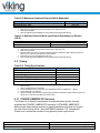
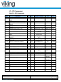
Ordering Information: mSATA SSD Solid-State Drive
Part Numbers
Interface
Application
Raw
Capacity
(GB)
Useable
Capacity
(GB)1
NAND
Technology
Temperature
Range
SATA 6Gbps
Client
16
12
MLC
0 to 70°C
VRFEM2012GJCRMTH
SATA 6Gbps
Client
32
30
MLC
0 to 70°C
VRFEM2030GJCRMTH
SATA
6Gbps
Client
32
30
MLC
0 to 70°C
VRFEM2030GHCYMTH
SATA 6Gbps
Client
64
55
MLC
0 to 70°C
VRFEM2055GJCYMTH
SATA
6Gbps
Client
128
120
MLC
0 to 70°C
VRFEM2120GHCTMTH
VRFEM2240GHCVMTH
SATA 6Gbps
Client
256
240
MLC
0 to 70°C
VRFEM2060GHCPSTF
SATA 6Gbps
Client
64
60
SLC
0 to 70°C
VRFEM2030GHCNSTF
SATA 6Gbps
Client
32
30
SLC
0 to 70°C
VRFEM2014GHCLSTF
SATA 6Gbps
Client
16
14
SLC
0 to 70°C
Notes:
1) Usable capacity based on a level of over-provisioning applied to wear leveling, bad sectors, index
tables etc.
2) Higher capacity points may be available based on customer application. Consult your local Viking
Field Application Engineer.
3) SSD’s ship unformatted from the factory unless otherwise requested.
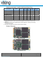
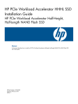
Product Picture(s)
mSATA Top View
mSATA Bottom View
Datasheet
PSFEM2XXXGXXXX
Revision A2
www.vikingtechnology.com
06/04/2012
Viking Technology
Page 4 of 46
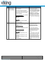
Viking’s solid state drives are available in Enterprise and Client versions:
Enterprise – An Enterprise SSD contains hardware and firmware that detect and
manage power failures. This allows the drive to flush the controller cache and
harden data to NAND flash. No data is lost or corrupted.
Client – A Client SSD does not include power failure detection or management
features. MLC NAND, as opposed to SLC NAND, can become corrupted if
power is removed during a write, also known as lower page corruption.
Therefore, a Client SSD using MLC NAND is well-suited in a system that already
manages power fail events, allowing for graceful SSD shutdown. Accordingly,
system support should include issuing a Standby Immediate command to the
SSD while maintaining power for at least 50ms.
If a Client drive with MLC NAND is used in a system that does not manage power
failures and shutdowns, there is a small chance of data corruption. Viking Client
SSDs take sophisticated hardware and firmware measures to prevent or mitigate
such issues making the chance of corruption very small.
If the SSD controller detects data corruption, the drive will be locked. The only
way to recover the drive is to return it to the factory for reprogramming; all data
will be lost.
Datasheet
PSFEM2XXXGXXXX
Revision A2
www.vikingtechnology.com
06/04/2012
Viking Technology
Page 5 of 46
Table of Contents
1
INTRODUCTION
9
1.1
Features
1.2
Block Diagram
10
1.3
SATA Interface
10
1.4
Indicator LEDs
11
2
PRODUCT SPECIFICATIONS
9
11
2.1
Capacity
11
2.2
Performance
11
2.3
Timing
2.3.1 STANDBY IMMEDIATE Command
12
12
2.4
Electrical Characteristics
2.4.1 Absolute Maximum Ratings
2.4.2 Supply Voltage
2.4.3 Supply Current
2.4.4 Power Consumption
13
13
13
13
14
2.5
Environmental Conditions
2.5.1 Temperature and Altitude
2.5.2 Shock and Vibration
2.5.3 Electromagnetic Immunity
14
14
14
15
2.6
Reliability
2.6.1 Data, MetaData, and Firmware Code Protection
2.6.2 Intelligent Read Disturb Management
2.6.3 Intelligent Write Operation Management
15
15
17
17
2.7
18
3
Data Security
MECHANICAL INFORMATION
Datasheet
PSFEM2XXXGXXXX
Revision A2
www.vikingtechnology.com
19
06/04/2012
Viking Technology
Page 6 of 46
3.1
4
mSATA SSD Weight
PIN AND SIGNAL DESCRIPTIONS
20
20
4.1
Signal and Power Description Tables
20
4.2
Hot Plug Support
21
5
COMMAND SETS
22
5.1
ATA Commands
5.1.1 48-Bit Address Command Set
5.1.2 ATA General Feature Command Set
5.1.3 Device Configuration Overlay Command Set
5.1.4 General Purpose Log Command Set
5.1.5 Host Protected Area Command Set
5.1.6 Power Management Command Set
5.1.7 Security Mode Feature Set
5.1.1 S.M.A.R.T. Support
5.1.2 S.M.A.R.T. Command Set
5.1.3 S.M.A.R.T. Attributes
5.1.4 Attribute Sector
5.1.5 Threshold Sector
5.1.6 S.M.A.R.T. Command Transport (SCT)
23
27
27
27
28
28
28
28
28
29
31
43
43
44
5.2
SATA Commands
5.2.1 Native Command Queuing (NCQ)
44
44
6
CERTIFICATIONS AND COMPLIANCE
45
7
REFERENCES
45
8
GLOSSARY
46
Datasheet
PSFEM2XXXGXXXX
Revision A2
www.vikingtechnology.com
06/04/2012
Viking Technology
Page 7 of 46
Table of Tables
Table 2-1: User Addressable Sectors _____________________________________________ 11
Table 2-2: Maximum Sustained Read and Write Bandwidth ____________________________ 12
Table 2-3: Random Read and Write Input/Output Operations per Second (IOPS) ___________ 12
Table 2-4: Timing Specifications _________________________________________________ 12
Table 2-5: STANDBY IMMEDIATE Timing _________________________________________ 13
Table 2-6: Absolute Maximum Ratings ____________________________________________ 13
Table 2-7: Operating Voltage ___________________________________________________ 13
Table 2-8: Current Draw _______________________________________________________ 13
Table 2-9: Typical Power Consumption ___________________________________________ 14
Table 2-10: Temperature and Altitude Related Specifications __________________________ 14
Table 2-11: Shock and Vibration Specifications _____________________________________ 14
Table 2-12: Reliability Specifications______________________________________________ 15
Table 4-1: Mini PCIe Connector Pin Signal Definitions ________________________________ 20
Table 5-1: ATA Feature Set ____________________________________________________ 22
Table 5-2: ATA Commands_____________________________________________________ 23
Table 5-3: S.M.A.R.T. Command Set _____________________________________________ 29
Table 5-4: Supported S.M.A.R.T. EXECUTE OFF-LINE IMMEDIATE Subcommands ________ 30
Table 5-5: Baseline S.M.A.R.T. Attribute Summary __________________________________ 31
Table 5-6: Baseline S.M.A.R.T. Attribute Details_____________________________________ 33
Table 5-7: S.M.A.R.T. Attribute Data Structure ______________________________________ 43
Table 5-8: S.M.A.R.T. Threshold Data Structure_____________________________________ 44
Table 6-1: Device Certifications _________________________________________________ 45
Table of Figures
Figure 1-1: High-Level Block Diagram ____________________________________________ 10
Figure 3-1: Dimensions ________________________________________________________ 19
Figure 5-1: S.M.A.R.T. ECC and RAISE Error Summary ______________________________ 42
Datasheet
PSFEM2XXXGXXXX
Revision A2
www.vikingtechnology.com
06/04/2012
Viking Technology
Page 8 of 46
1 Introduction
Viking’s rugged industrial designed SSD’s offer the highest flash storage
reliability and performance in harsh environments such as shock, vibration,
humidity, altitude, ESD, and extreme temperatures. Viking SSD’s meet JEDEC
JESD22 standards and pass numerous qualifications (i.e. MIL-STDs and NEBS).
Viking can also provide specialized services to OEMs designing customized
hardware and systems by offering:
Locked BOM control with customer product change notification (PCN)
Pre-installed software, custom software imaging and ID strings
Custom packaging and labeling
Comprehensive supply-chain management
Customer specified testing
30K volt ESD protection
Conformal coating
Localized Field Application Engineering for complete pre and post sale
technical support
1.1 Features
The mSATA delivers the following enterprise SSD features:
Best in class sequential and random performance
Seamless SATA Revision 3.x interface support for SATA up to 6Gb/s)
Ultra small form factor (approx 30 x 50mm, about 1/3rd as long as a credit
card and just as wide
Low overall SSD power consumption
Patented architecture for SSD longevity, reliability and data integrity
RAISE – Redundant Array of Independent Silicon Elements
Supports Native Command Queuing (NCQ) to 32 commands
Compatible with all major SLC and MLC flash technologies
Protection against catastrophic flash page and block failures
AES-128 encryption in CTR mode and AES-256 encryption in XTS mode
S.M.A.R.T. command transport (SCT) technology
Superior wear-leveling algorithm
Intelligent flash memory block management and read disturb management
Efficient error recovery
Power-throttling support
Thermal sensing energy management
RoHS compliant
Automatic Trim Command support
Datasheet
PSFEM2XXXGXXXX
Revision A2
www.vikingtechnology.com
06/04/2012
Viking Technology
Page 9 of 46
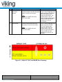
1.2 Block Diagram
Figure 1-1: High-Level Block Diagram
1.3 SATA Interface
The Serial ATA (SATA) interface is compliant with the SATA IO Serial
ATA specification, revision 3.x that supports SATA up to 6GB/s.
The SATA interface connects the host computer to the SSD subsystem.
The SATA interface runs at a maximum speed of 6.0 Gbps (gigabits per
second). If the host computer is unable to negotiate a speed of 6.0 Gbps,
the SATA interface automatically renegotiates to a speed of 3 Gbps.
For a list of supported commands and other specifics, please see Chapter 5.
Datasheet
PSFEM2XXXGXXXX
Revision A2
www.vikingtechnology.com
06/04/2012
Viking Technology
Page 10 of 46
1.4 Indicator LEDs
There is a Green LED indicator on the mSATA module that will flash to indicate a
SATA activity condition. The Red LED indicates a fault condition. There is also a
remote LED indicator at Pin 49 called “Device Activity Signal”. For a remote LED
application, an LED should be tied high through a current limiting resistor on the
host side. The mSATA will sink current on the module to allow the LED to flash to
indicate an ACTIVITY. If a remote LED is not implemented, pin 49 may be
connected to GND to allow the ACTIVITY LED to remain on and indicate a
Power On condition.
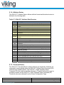
2 Product Specifications
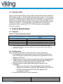
2.1 Capacity
Table 2-1: User Addressable Sectors
Raw Capacity
256 GB
128 GB
64 GB
32 GB
16 GB
Minimum Total User Addressable Sectors in LBA
Mode
468,862,128
195,371,568
97,696,368
48,858,768
23,463,216
Notes:
1. 1 GB = 1,000,000,000 Byte and not all of the memory can be used for data storage. Usable
capacity based on 28% over-provisioning applied to wear leveling, bad sectors, index tables etc.
2. One Sector = 512 Byte.
2.2 Performance
Maximum SSD performance can be achieved for certain workloads by:
Initiating read and write transfers for random accesses with small block
sizes of 4K bytes to optimize IOPs performance for applications such as
databases, OLTP etc.
Initiating read and write transfers for sequential accesses with large blocks
(128K or larger) to optimize performance toward throughput (MBps) for
applications such as video streaming, data acquisition etc.
Issuing transfers at starting LBAs which align the access on 4K
boundaries:
o Minimizes or eliminates internal Read-Modify-Write operations
o Align on 4K boundaries is optimal for SSD capacities up to 256 GB
o For SSD capacities greater than 256 GB, aligning on 8K
boundaries is optimal
Avoid mixing NCQ and non-NCQ commands
Datasheet
PSFEM2XXXGXXXX
Revision A2
www.vikingtechnology.com
06/04/2012
Viking Technology
Page 11 of 46
Table 2-2: Maximum Sustained Read and Write Bandwidth
Access Type
Sequential Read, 128K
Sequential Write, 128K
MB/s
Up to 520
Up to 520
Notes:
1. Performance measured using IOmeter 08 with queue depth set to 32.
2. Write Cache enabled.
3. Refer to Application Note AN0006 for Viking SSD Benchmarking Methodology.
Table 2-3: Random Read and Write Input/Output Operations per Second
(IOPS)
Access Type
Read, 4K
Write, 4K
IOPS
60,000
60,000
Notes:
1. Performance measured using Iometer 08 with queue depth set to 32.
2. Write Cache enabled.
3. Random IOPS cover the entire range of legal logical block addresses (LBAs). Measurements are
performed on a full drive (all LBAs have valid content).
4. Performance may vary by NAND type and host.
5. Refer to Application Note AN0006 for Viking SSD Benchmarking Methodology.
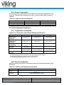
2.3 Timing
Table 2-4: Timing Specifications
Type
Power On to Ready
Reset to Ready
Sleep to Ready
Command to DRQ
Time to Erase (ATA Secure Erase)
Time to Erase (ATA Secure Erase with flash erase)
Notes:
1.
2.
3.
4.
5.
Average Latency (ms)
<1
<2
<1
<1
4 seconds
~ 1 GB/second
Based on MLC
Device measured using Drivemaster.
Sector Read/Write latency measured up to 2048 block transfers (512B/sector = 1 Block)
Queue depth set to 32 for NCQ
Sequential IOPS cover the entire range of legal logical block addresses (LBAs). Measurements are
performed on a full drive (all LBAs have valid content
2.3.1 STANDBY IMMEDIATE Command
The Power On to Ready time assumes a proper shutdown (power removal
preceded by STANDBY IMMEDIATE command. A STANDBY IMMEDIATE
before power down always performs a graceful shutdown and does not require
the use of the hold-up circuit. Note that SMART attribute 174 "Unexpected
Power Loss" records the number of non-graceful power cycle events.
Datasheet
PSFEM2XXXGXXXX
Revision A2
www.vikingtechnology.com
06/04/2012
Viking Technology
Page 12 of 46
Table 2-5: STANDBY IMMEDIATE Timing
Power Cycle Endurance
Min
STANDBY IMMEDIATE to WE completed
Max
40
Unit
ms
2.4 Electrical Characteristics
2.4.1 Absolute Maximum Ratings
Values shown are stress ratings only. Functional operation outside normal
operating values is not implied. Extended exposure to absolute maximum ratings
may affect reliability.
Table 2-6: Absolute Maximum Ratings
Description
Maximum Voltage Range for Vin
Maximum Temperature Range
Min
-0.2
-40
Max
6
85
Unit
V
c
Min
3.135
Max
3.465
Unit
V
2.4.2 Supply Voltage
The operating voltage is 3.3V.
Table 2-7: Operating Voltage
Description
Operating Voltage for 3.3 V (+/- 5%)
2.4.3 Supply Current
Table 2-8: Current Draw
Mode
Read/Writes (Average RMS)
Maximum Peak
Low Power Standby
( Host Sleep Mode Current)
Typical1
200
400
Unit
mA
mA
<150
mA
Notes:
1. Table values based on 128GB drive.
Datasheet
PSFEM2XXXGXXXX
Revision A2
www.vikingtechnology.com
06/04/2012
Viking Technology
Page 13 of 46
2.4.4 Power Consumption
All onboard power requirements of the mSATA are derived from the SATA 3.3V
input rail. Typical power consumption is that of a device with 64GB of physical
capacity.
Table 2-9: Typical Power Consumption
Mode
Active
Idle
Low Power Standby
Typical
< 3.35
<1.0
<800
Unit
W
W
mW
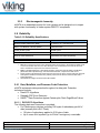
2.5 Environmental Conditions
2.5.1 Temperature and Altitude
Table 2-10: Temperature and Altitude Related Specifications
Conditions
Commercial
Temperature
- Ambient
Industrial
Temperature1
- Ambient
Humidity (noncondensing)
Max Temperature
Gradient
Altitude
Storage Time
Duration
Operating
0 to 70°C
(32 to 158° F)
Shipping
-40 to 85°C
(-40 to 185° F)
Storage
-40 to 85°C
(-40 to 185° F)
-40 to 85°C
(-40 to 185° F)
-40 to 85°C
(-40 to 185° F)
-40 to 85°C
(-40 to 185° F)
10% to 80%
5% to 95%
5% to 95%
20°C/Hour
(36°F/Hour)
-304.8 to 24,384 m
(-1,000 to 80,000 ft)
n/a
n/a
n/a
-304.8 to 24,384 m
(-1,000 to 80,000 ft)
n/a
-304.8 to 24,384 m
(-1,000 to 80,000 ft)
1 year
Notes:
1. SLC flash based products are available in the following temperature ranges:
a) Commercial temperature range of 0 to 70°C (32 to 158° F)
b) Industrial temperature range -40 to 85°C (-40 to 185° F)
2.5.2 Shock and Vibration
mSATA products are tested in accordance with environmental specification MILSTD-810F.
Table 2-11: Shock and Vibration Specifications
Shock
Vibration
Datasheet
PSFEM2XXXGXXXX
Revision A2
www.vikingtechnology.com
Description
50g, 11ms, 3 shocks applied in each direction on 3 mutually perpendicular
axes X, Y, Z
16.4g rms 10-2,000 Hz, 3 axes
06/04/2012
Viking Technology
Page 14 of 46
2.5.3
Electromagnetic Immunity
mSATA is an embedded product for host systems and is designed not to impair
with system functionality or hinder system EMI/FCC compliance.
2.6 Reliability
Table 2-12: Reliability Specifications
Parameter
Value
Nonrecoverable read errors (BER)1
<1 sector in 1017 bits read, max
Mean Time Between Failures (MTBF)2
3,000,000 hours
Power On/Off Cycles3
50,000 cycles
Read Endurance
Write or Erase Endurance
Global wear-leveling
Data retention
Unlimited
4
(specified by the flash component)
~ 2% between least worn and most worn
>10 years
Notes:
1. BER will not exceed one sector in the specified number of bits read. In the extremely unlikely event
of a non-recoverable read error, the drive will report it as a read failure to the host; the sector in
error is considered corrupt and is not returned to the host.
2. MTBF is calculated based on a Part Stress Analysis. It assumes nominal voltage, with all other
o
parameters within specified range. Telcordia method SR-332, component FIT rate at 55 c.
3. Power On/Off Cycles defined as power being removed from the drive, and then restored. Note that
host systems and drive enclosures may remove power from the drive for reasons other than a
system shutdown.
4. SLC NAND has a higher endurance then MLC NAND
2.6.1 Data, MetaData, and Firmware Code Protection
mSATA implements data protection throughout its data path. Protection
techniques include:
Data ECC Algorithms
Datapath CRC Error Detection
RAISETM Data Protection Against Catastrophic Flash Page/Block Failure
2.6.1.1 DATA ECC Algorithms
The following data error correction is provided:
For Flash memory devices providing 128 bytes of redundancy per 4K of
data (normally this is SLC Flash)
o 16 bytes of redundancy applied to 512 bytes of data
o Up to seven 9-bit symbols (up to 63 bits if contiguous) correctable
Datasheet
PSFEM2XXXGXXXX
Revision A2
www.vikingtechnology.com
06/04/2012
Viking Technology
Page 15 of 46
For Flash memory devices providing 218 or more bytes of redundancy per
4K of data (normally this is MLC Flash)
o 27 bytes of redundancy applied to 512 bytes of data
o Up to twelve 9-bit symbols (up to 108 bits if contiguous) correctable
2.6.1.2 Data Path CRC Error Detection
CRC error detection is applied against data along internal data paths. CRC
detection uses a 32-bit checksum (CRC32) to protect data along all internal data
paths.
2.6.1.3 RAISETM Data Protection Against Catastrophic Flash Page/Block
Failure
mSATA implements proprietary R.A.I.S.E.TM (Redundant Array of Independent
Silicon Elements) data protection, to overcome the probabilistic risk of page or
block failure inherent in all Flash memory technology.
Flash technology can exhibit a finite probability that a block or page will fail within
the rated Program-Erase (P-E) cycle count lifetime of the Flash device. While this
probability may appear tolerable for a given application, note that it is for a
particular Flash die. For an SSD incorporating up to 128 Flash die, the additive
probability of this phenomenon can reveal measurable risk to the SSD over its
multi-year lifetime.
mSATA technology addresses this risk. In the event of a catastrophic failure of
an entire Flash page or Flash block, RAISETM off-line protection rebuilds the data
in the failed page or block and relocates it elsewhere in the Flash array.
Performance during recovery is impacted, but after recovery is complete, mSATA
returns to full performance and full functionality. The performance impact period
is only the amount of time required to rebuild and relocate the page or block data,
and to map out the problematic Flash block.
In contrast to other SSD Flash controllers, mSATA with RAISETM technology
uniquely, reliably and seamlessly overcomes these catastrophic data loss risks
with only temporary impact to throughput and latency and no impact to power
consumption. In a RAID drive array application, mSATA can auto-rebuild data
locally, without passing the problem upstream to the system level and without
incurring the associated significant system rebuild hit. The difference in impact
between a standard approach and mSATA with RAISETM approach is significant.
Additionally, following recovery from a page failure or block failure, mSATA is
fully functional and fully reliable, whereas a page-failed or block-failed drive
recovered by system RAID must be immediately replaced.
Datasheet
PSFEM2XXXGXXXX
Revision A2
www.vikingtechnology.com
06/04/2012
Viking Technology
Page 16 of 46
2.6.1.4 Firmware Code Protection
Firmware requires special attention to ensure the code is execution-worthy. For
this reason, firmware is stored in multiple redundant images in the Flash array.
Image checksums are compared between all stored copies to ensure identical
code. Any image not corroborated by at least one other image is discarded. In
this way a reliable firmware image is always chosen on boot-up for execution.
If a firmware image is discarded, a new redundant image is created from the
good images to ensure original levels of protection.
Firmware images are also protected in Flash memory and during fetch by the
maximum ECC correction power, and by RAISETM correction technology.
2.6.2 Intelligent Read Disturb Management
Flash memory is primarily at risk from writes and erasures. However, reads also
affect data longevity. Excessive reads of Flash memory cells induce inter-cell
voltage shift, although the effect not as accelerated as write-induced cell
damage. The degradation occurs in data stored in nearby cells, rather than in the
cell being read. Read-induced data degradation is called “Read Disturb.”
The controller provides read operation management to overcome Flash Memory
“Read Disturb” concerns by ensuring that data integrity is not impacted by
multiple reads of the same Flash Memory address. It tracks reads and
automatically and seamlessly recovers and refreshes data in proximity before
that data is negatively impacted. Its superior throughput and latency
performance, delivered over the life of the drive, is not diminished by this process
and the expected data retention capability is assured throughout the warranted
life of the SSD.
2.6.3 Intelligent Write Operation Management
The controller makes data location/relocation decisions which greatly increase
the life of the SSD.
2.6.3.1 Sophisticated Wear-Leveling
Wear leveling refers to the practice of equalizing the impact of write and erase
operations over the larger pool of Flash memory blocks. Industry-standard wear
leveling techniques focus on conventional schemes that attempt to equalize
writes and erases across blocks. While on the surface this appears to be a
reasonable approach, it is clear that it assumes all blocks will “wear” equally
when written or erased. This is far from the truth. The NAND processor takes
much more into account. It measures a variety of parameters to determine the
actual wear of blocks during P-E cycles, to determine which blocks are impacted
Datasheet
PSFEM2XXXGXXXX
Revision A2
www.vikingtechnology.com
06/04/2012
Viking Technology
Page 17 of 46
more by erasures and writes over time. That is, it determines actual cell wear, not
simply assumed wear normalized to write/erase events. The controller employs
this information in its superior wear-leveling algorithm along with its ongoing
record of writes and erasures, to ensure each block is impacted by P-E cycles no
more than the average. The result is an SSD that is far more reliable across its
full capacity and over a far greater length of time. The controller uses both static
and dynamic wear-leveling algorithms to globally manage cell degradation to
approximately 2% between least worn and most worn cells or to the value
specified in the S.M.A.R.T Wear Range Delta command (ID=177,
Opcode=0xB1)
2.6.3.2 Write Operation Reduction
The controller uses intelligent algorithms to minimize P-E cycles through
aggregation, virtualization, and difference processing. It is uniquely effective in
reducing the wear and maintaining the reliability of the overall pool of Flash
memory blocks by intelligently minimizes re-writes of identical data, to maximize
the effectiveness of the wear-leveling process.
2.7 Data Security
Viking MSATA SSD’s are self-encrypting drives (SED), with a bulk data
encryption feature that provides automatic hardware-based data security and
enhanced secure erase capability.
A self-encrypting drive, scrambles data using a data encryption key as it is
written to the drive and then descrambles it with the key as it is retrieved. This
gives the user the highest level of data protection available and provides a fast
erase simply by deleting the encryption key, eliminating the need for time
consuming data-overwrite. Data on the drive is instantly rendered unreadable.
The MSATA SSD supports AES-128 encryption, AES-256 encryption and ATA
Secure Erase features to protect sensitive data. The drive is also available with
TCG security enhancements.
Datasheet
PSFEM2XXXGXXXX
Revision A2
www.vikingtechnology.com
06/04/2012
Viking Technology
Page 18 of 46
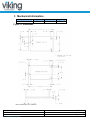
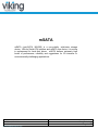
3 Mechanical Information
Form Factor
Full size
Height (mm)
4.85 max
Width (mm)
29.85 max
Length (mm)
50.80 max
Figure 3-1: Dimensions
Notes: All dimensions are in millimeters
Datasheet
PSFEM2XXXGXXXX
Revision A2
www.vikingtechnology.com
06/04/2012
Viking Technology
Page 19 of 46
3.1 mSATA SSD Weight
The weight of an mSATA (mini-SATA, MO-300) is approximately 7.8 grams.
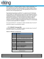
4 Pin and Signal Descriptions
4.1 Signal and Power Description Tables
Table 4-1: Mini PCIe Connector Pin Signal Definitions
Pin #
P1
P2
P3
P4
P5
P6
P7
P8
P9
P10
P11
P12
P13
P14
P15
P16
P17
P18
P19
P20
P21
P22
P23
P24
P25
P26
P27
P28
P29
P30
Datasheet
PSFEM2XXXGXXXX
Revision A2
www.vikingtechnology.com
Type
Reserved
+3.3V
Reserved
GND
Reserved
Reserved
Reserved
Reserved
GND
Reserved
Reserved
Reserved
Reserved
Reserved
GND
Reserved
Reserved
GND
Reserved
Reserved
GND
Reserved
+B
+3.3V
-B
GND
GND
Reserved
GND
Two Wire Interface
Description
No Connect
3.3V Source
No Connect
Return Current Path
No Connect
No Connect
No Connect
No Connect
Return Current Path
No Connect
No Connect
No Connect
No Connect
No Connect
Return Current Path
No Connect
No Connect
Return Current Path
No Connect
No Connect
Return Current Path
No Connect
Host Receiver Differential Signal Pair
3.3V Source
Host Receiver Differential Signal Pair
Return Current Path
Return Current Path
No Connect
Return Current Path
Two Wire Interface Clock3
06/04/2012
Viking Technology
Page 20 of 46
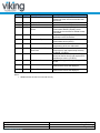
Pin #
P31
P32
P33
P34
P35
P36
P37
P38
P39
P40
P41
P42
P43
P44
P45
P46
P47
Reserved
Type
-A
Two Wire Interface
+A
GND
GND
Reserved
GND
Reserved
+3.3V
GND
+3.3V
Reserved
GND
Reserved
Vendor
Reserved
Vendor
No Connect
P49
P50
P51
P52
DA/DSS
GND
Presence Detection
+3.3V
Description
Host Transmitter Differential Signal Pair
Two Wire Interface Data3
Host Transmitter Differential Signal Pair
Return Current Path
Return Current Path
No Connect
Return Current Path
No Connect
3.3V Source
Return Current Path
3.3V Source
No Connect
Return Current Path
No Connect
Vendor Specific / Manufacturing Pin2
No Connect
Vendor Specific / Manufacturing Pin2
Reserved
Device Activity Signal / Disable Staggered Spinup
Return Current Path
Shall be pulled to GND by device1
3.3V Source
Notes:
1. Presence detection pin provided for tamper proof functionality
2. No connect on the host side.
3. Pins 30 and 32 are intended for use as a two wire interface to read a memory device to determine device
information (an example of this would be for use as SMB bus pins). These pins are not designed to be
active in conjunction with the SATA signal differential pairs.
4.2 Hot Plug Support
Hot Plug insertion and removal are supported in the presence of a proper
connector and appropriate operating system (OS) support as described in the
SATA 3.0 specification. This product supports Asynchronous Signal Recovery
and will issue an unsolicited COMINIT when first mated with a powered
connector to guarantee reliable detection by a host system without hardware
device detection.
Datasheet
PSFEM2XXXGXXXX
Revision A2
www.vikingtechnology.com
06/04/2012
Viking Technology
Page 21 of 46
5 Command Sets
mSATA complies with ATA-8. All mandatory and many optional commands and
features are supported. The tables below summarize the supported ATA feature
set and commands.
Table 5-1: ATA Feature Set
Support
Feature Set
ATA-8 REF
ATA Device
MSATA
General feature set
4.2
M
YES
PACKET feature set
4.3
P
NO
48-Bit Address feature set
Advanced Power Management (APM) feature
set
Automatic Acoustic Management (AAM)
feature set
4.4
O
YES
4.5
O
NO
4.6
O
NO
CompactFlash Association (CFA) feature set
Device Configuration Overlay (DCO) feature
set
4.7
N
NO
4.8
O
YES
Free-fall Control feature set
4.9
O
NO
General Purpose Logging (GPL) feature set
4.10
O
YES
Host Protected Area (HPA) feature set
4.11
O
YES
Long Logical Sector (LLS) feature set
4.12
O
NO
Long Physical Sector (LPS) feature set
Media Card Pass Through Command feature
set
4.13
O
NO
4.14
N
NO
Native Command Queuing (NCQ) feature set
4.15
O
YES
NV Cache feature set
4.16
O
NO
NV Cache Power Management feature set
4.17
O
NO
Power Management feature set
4.18
M
YES
Power-Up In Standby (PUIS) feature set
4.19
O
YES
Security feature set
4.20
O
YES
S.M.A.R.T. feature set
Software Settings Preservation (SSP) feature
set
4.21
O
YES
4.22
O
YES
Streaming feature set
4.23
O
NO
Tagged Command Queuing (TCQ) feature set
4.24
O
NO
Trusted Computing feature set
4.25
O
NO
Write-Read-Verify feature set
4.26
O
NO
Key: M – Mandatory, O – Optional, P – Prohibited, N – Not defined, YES – Supported, NO
– Not Supported
Datasheet
PSFEM2XXXGXXXX
Revision A2
www.vikingtechnology.com
06/04/2012
Viking Technology
Page 22 of 46
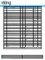
5.1 ATA Commands
Table 5-2: ATA Commands
ATA-8
REF
7.2
ATA8
N
Sup
p
NO
Key Word Option
CfaEraseSec, CFES
Feature
Set
CFA
OP
C0h
CFA REQUEST EXTENDED ERROR
CODE
CFA TRANSLATE SECTOR
O
NO
CfaReqErr, CFRE
CFA
03h
O
NO
CfaTransSec, CFTS
CFA
87h
O
NO
CfaWrMul, CFWM
CFA
CDh
O
NO
CfaWrSec, CFWS
CFA
38h
7.7
CFA WRITE MULTIPLE WITHOUT
ERASE
CFA WRITE SECTOR(S) WITHOUT
ERASE
CHECK MEDIA CARD TYPE
O
NO
ChkMedType, CHMT
Media Card
D1h
7.8
CHECK POWER MODE
M
YES
ChkPwrMode, CKPW,
CHPW
CfgStr, CFST
Power
Manage
Streaming
E5h
DCO
Packet
B1h/C1
h
B1h/C2
h
B1h/C0
h
B1h/C3
h
08h
General
92h
7.3
7.4
7.5
7.6
7.9
Commands
CFA ERASE SECTORS
CONFIGURE STREAM
O
NO
DEVICE CONFIGURATION FREEZE
LOCK
DEVICE CONFIGURATION
IDENTIFY
DEVICE CONFIGURATION
RESTORE
DEVICE CONFIGURATION SET
O
YES
O
YES
O
YES
O
YES
7.11
DEVICE RESET
N
NO
DevCfgFrzLock,
DCOF, DCFL
DevCgfIdfy, DCOI,
DCFI
DevCfgRestore,
DCOR, DEFR
DevCfgSet, DCOS,
DCFS
DevRst, DRST
7.12
DOWNLOAD MICROCODE
O
YES
Download, DNLD
7.13
EXECUTE DEVICE DIAGNOSTIC
M
YES
Diagnose, DIAG
General
90h
7.14
FLUSH CACHE
M
YES
FlushCache, FLSH
General
E7h
7.15
FLUSH CACHE EXT
M
YES
IDENTIFY DEVICE
M
YES
48-bit
Address
General
EAh
7.16
FlushCacheEx, FLSE,
FLEX
Identify, IDFY
ECh
7.17
IDENTIFY PACKET DEVICE
N
NO
IdfyPktDev, IDPD
Packet
A1h
7.18
IDLE
M
YES
IDLE
E3h
7.19
IDLE IMMEDIATE
M
YES
IDLI
Power
Manage
Power
Manage
IDLE/UNLOAD IMMEDIATE
O
YES
-
INITIALIZE DRIVE PARAMETERS
M
YES
7.20.3
O
NO
NV Cache
7.20.4
ADD LBA(S) TO NV CACHE PINNED
SET
FLUSH NV CACHE
O
NO
NV Cache
7.20.5
NV CACHE DISABLE
O
NO
NV Cache
7.10.2
7.10.3
7.10.4
7.10.5
-
Datasheet
PSFEM2XXXGXXXX
Revision A2
www.vikingtechnology.com
DCO
DCO
DCO
51h
E1h
E1h41h
91h
B6h/10
h
B6h/14
h
B6h/16
h
06/04/2012
Viking Technology
Page 23 of 46
ATA-8
REF
7.20.6
Commands
NV CACHE ENABLE
ATA8
O
Sup
p
NO
7.20.7
QUERY NV CACHE MISSES
O
NO
NV Cache
7.20.8
QUERY NV CACHED PINNED SET
O
NO
NV Cache
7.20.9
REMOVE LBA(S) FROM CACHED
PINNED SET
RETURN FROM NV CACHE POWER
MODE
SET NV CACHE POWER MODE
O
NO
NV Cache
O
NO
NV Cache
O
NO
NV Cache
NOP
O
YES
NOP
7.20.1
0
7.20.1
1
7.21
Key Word Option
Feature
Set
NV Cache
General
OP
B6h/15
h
BRh/13
h
B6h/12
h
B6h/11
h
B6h/01
h
B6h/00
h
00h
7.22
PACKET
O
NO
Packet, PAKT
Packet
A0h
7.23
READ BUFFER
O
YES
RdBuf, RBUF
General
E4H
7.24
READ DMA
M
YES
RdDma, RDMA
General
C8h
7.25
READ DMA EXT
M
YES
RdDmaEx, RDMX
25h
7.26
READ DMA QUEUED
O
NO
RdDmaQ, RDMQ
48-bit
Address
TCQ
RdDmaQEx, RDQX
TCQ
7.27
-
READ DMA QUEUED EXT
READ DMA (w/o retry)
O
NO
Obs
YES
7.28
READ FPDMA QUEUED
M
YES
7.29
READ LOG EXT
M
YES
7.30
READ LOG DMA EXT
O
YES
7.31
READ MULTIPLE
M
YES
7.32
READ MULTIPLE EXT
M
YES
C7h
26h
C9h
RFPDMAQ,
RDMA_NCQ
RdLogEx, RLEX
NCQ
60h
GPL
2Fh
47h
RdMul, RMUL
48-bit
Address
General
RdMulEx, RDME,
RMEX
RdNativeMax, RNMA
48-bit
Address
HPA
29h
F8h
RdNativeMaxEx,
RNME
RdSec, RDSK, REC
HPA
27h
General
20h
48-bit
Address
Streaming
24h
2Ah
Streaming
2Bh
7.33
READ NATIVE MAX ADDRESS
M
YES
7.34
READ NATIVE MAX ADDRESS EXT
M
YES
7.35
READ SECTOR(S)
M
YES
7.36
READ SECTOR(S) EXT
M
YES
7.37
READ STREAM DMA EXT
O
NO
RdSecEx, RDSE,
RSEX
RdStrDma, RSTD
7.38
READ STREAM EXT
O
NO
RdStrPio, RSTP
C4h
7.39
READ VERIFY SECTOR(S)
M
YES
RdVfy, RVFE
General
40h
7.40
READ VERIFY SECTOR(S) EXT
M
YES
RdVfyEx, RVFE
48-bit
Address
42h
Obs
YES
41h
-
READ VERIFY SECTORS(S) (w/o
retry)
RECALIBRATE
Obs
YES
10h
7.41
SECURITY DISABLE PASSWORD
M
YES
-
Datasheet
PSFEM2XXXGXXXX
Revision A2
www.vikingtechnology.com
SecuDisPsw, SEDP
Security
F6h
06/04/2012
Viking Technology
Page 24 of 46
ATA-8
REF
7.42
ATA8
M
Sup
p
YES
Feature
Set
Security
OP
F3h
Security
F4h
Security
F5h
7.43
SECURITY ERASE UNIT
M
YES
Key Word Option
SecuErasePrep,
SERP
SecuEraseUnit, SEEU
7.44
SECURITY FREEZE LOCK
O
YES
SecuFrzLock, SFZL
7.45
SECURITY SET PASSWORD
M
YES
SecuSetPsw, SESP
Security
F1h
7.46
SECURITY UNLOCK
M
YES
SecuUnlock, SEUL
Security
F2h
SEEK
M
YES
7.47
SERVICE
O
NO
Service, SRVC
TCQ
70h7Fh
A2h
7.48
SET FEATURES
M
YES
SetFeature, SETF
General
EFh
7.49.2
SET MAX ADDRESS
M
YES
HPA
F9h
7.49.3
SET MAX FREEZE LOCK
O
YES
SetMaxAddr, SMXA,
SMAX
SetMaxFrzLock, SMFL
HPA
7.49.4
SET MAX LOCK
O
YES
SetMaxLock, SMLK
HPA
7.49.5
SET MAX SET PASSWORD
O
YES
HPA
7.49.6
SET MAX UNLOCK
O
YES
SetMaxSetPswd,
SMSP
SetMaxUnlock, SMUN
7.50
SET MAX ADDRESS EXT
M
YES
SetMaxEx, SAME
HPA
F9h/04
h
F9h/02
h
F9h/01
h
F9h/03
h
37h
7.51
SET MULTIPLE MODE
M
YES
SetMul, SMUL
General
C6h
7.52
SLEEP
M
YES
Sleep, SLEP
E6h
SMART DISABLE OPERATION
M
YES
SmDisable, SDSO,
SMDI
Power
Manage
SMART
Obs
YES
M
YES
M
YES
-
7.53.2
7.53.3
7.53.4
7.53.5
Commands
SECURITY ERASE PREPARE
SMART ENABLE/DISABLE AUTO
OFF-LINE
SMART ENABLE/DISABLE
AUTOSAVE
SMART ENABLE OPERATION
O
YES
7.53.6
SMART EXECUTE OFFLINE
IMMEDIATE
SMART READ DATA
O
YES
7.53.7
SMART READ LOG
O
YES
Obs
YES
O
YES
Obs
YES
O
YES
7.53.8
7.53.9
SMART READ THRESHOLD
SMART RETURN STATUS
SMART SAVE ATB VALUES
SMART WRITE LOG
Datasheet
PSFEM2XXXGXXXX
Revision A2
www.vikingtechnology.com
HPA
SMART
SmAutoSv, SAAS,
SMAS
SmEnable, SESO,
SMEN
ExeSmOL, SEOI,
SMOI
SmRdData, SRLS,
SMRD
SmRdLog, SRLS,
SMRL
SMART
SMART
SMART
SMART
SMART
SMART
SmStatus, SRSS
SMART
SMART
SmWrLog, SWLS,
SMWL
SMART
B0h/D9
h
B0hDBh
B0h/D2
h
B0h/D8
h
B0h/D4
h
B0h/D0
h
B0h/D5
h
B0hD1h
B0h/D
Ah
B0hD3h
B0h/D6
h
06/04/2012
Viking Technology
Page 25 of 46
ATA-8
REF
7.54
7.55
STANDBY IMMEDIATE
M
YES
7.56
TRUSTED NON-DATA
O
NO
Feature
Set
Power
Manage
Power
Manage
Trusted
7.57
TRUSTED RECEIVE
O
NO
Trusted
7.58
TRUSTED RECEIVE DMA
O
NO
Trusted
5Dh
7.59
TRUSTED SEND
O
NO
Trusted
5Eh
7.60
TRUSTED SEND DMA
O
NO
Trusted
5Fh
7.61
WRITE BUFFER
O
YES
General
E8h
7.62
WRITE DMA
M
YES
WdDma, WDMA
General
CAh
7.63
WRITE DMA EXT
M
YES
WrDmaEx, WDMX
35h
7.64
WRITE DMA FUA EXT
M
YES
WrDmaFuaEx, WDFE
7.65
WRITE DMA QUEUED
O
NO
WrDmaQ, WDMQ
48-bit
Address
48-bit
Address
TCQ
CCh
7.66
WRITE DMA QUEUED EXT
O
NO
WrDmaQEx, WDQX
TCQ
36h
7.67
WRITE DMA QUEUE FUA EXT
O
NO
WrDmaQFuaEx,
WDQF
TCQ
3Eh
Obs
YES
YES
-
Commands
STANDBY
WRITE DMA (w/o retry)
ATA8
M
Sup
p
YES
Key Word Option
Standby, STBY
StandbyIm, STBI
WrBuf, WBUF
OP
E2h
E0h
5Bh
5Ch
3Dh
CBh
7.68
WRITE FPDMA QUEUED
M
7.69
WRITE LOG EXT
M
YES
7.70
WRITE LOG DMA EXT
O
YES
7.71
WRITE MULTIPLE
M
YES
WrMul, WMUL
General
C5h
7.72
WRITE MULTIPLE EXT
M
YES
WRITE MULTIPLE FUA EXT
M
YES
7.74
WRITE SECTOR(S)
M
YES
WrSec, WDSK, WSEC
48-bit
Address
48-bit
Address
General
39h
7.73
WrMulEx, WDME,
WMEX
WrMulFuaEx, WMFE
7.75
WRITE SECTOR(S) EXT
M
YES
WrSecEx, WDSE,
WSEX
48-bit
Address
34h
-
WRITE SECTOR(S) (w/o retry)
WFPDMAQ,
WDMA_NCQ
WrLogEx, WRLE
NCQ
61h
GPL
3Fh
57h
CEh
30h
Obs
YES
7.76
WRITE STREAM DMA EXT
O
NO
WrStrDma, WSTD
Streaming
31h
3Ah
7.77
WRITE STREAM EXT
O
NO
WrStrPio, WSTP
Streaming
3Bh
7.78
WRITE UNCORRECTABLE EXT
O
YES
45h
-
DATA SET MANAGEMENT EXT (I.E.
O
YES
06h
TRIM)
Key: M – Mandatory, O – Optional, Obs – Obsolete, P – Prohibited, N – Not defined, YES – Supported, NO
– Not Supported
Datasheet
PSFEM2XXXGXXXX
Revision A2
www.vikingtechnology.com
06/04/2012
Viking Technology
Page 26 of 46
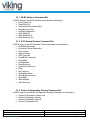
5.1.1 48-Bit Address Command Set
mSATA supports the 48-Bit Address command set consisting of:
Flush Cache Ext
Read DMA Ext
Read native Max Address Ext
Read Sector(s) Ext
Set Max Address Ext
Write DMA Ext
Write Multiple Ext
Write Sector(s) Ext
5.1.2 ATA General Feature Command Set
mSATA supports the ATA General Feature command set consisting of:
Download Microcode
Executive Device Diagnostics
Flush Cache
Identify Device
NOP (optional)
Read Buffer (optional)
Read DMA
Read Multiple
Read Sector(s)
Read Verify Sector(s)
Seek
Set Features
Set Multiple Mode
Write Buffer (optional)
Write DMA
Write Multiple
Write Sector(s)
5.1.3 Device Configuration Overlay Command Set
mSATA supports the Device Configuration Overlay command set consisting of:
Device Configuration Freeze Lock
Device Configuration Identity
Device Configuration Restore
Device Configuration Set
Datasheet
PSFEM2XXXGXXXX
Revision A2
www.vikingtechnology.com
06/04/2012
Viking Technology
Page 27 of 46
5.1.4 General Purpose Log Command Set
mSATA supports the General Purpose Log command set consisting of:
Read Log Ext
Write Log Ext
5.1.5 Host Protected Area Command Set
mSATA supports the Host Protected Area command set consisting of:
Read Native Max Address
Read Native Max Address Ext
Set Max Address
Set Max Address Ext
Set Max Freeze Lock (optional)
Set Max Lock (optional)
Set Max Set Password (optional)
Set Max Unlock (optional)
5.1.6 Power Management Command Set
mSATA supports the Power Management command set consisting of:
Check Power Mode
Idle
Idle Immediate
Sleep
Standby
Standby Immediate
5.1.7 Security Mode Feature Set
mSATA supports the Security Mode command set consisting of:
Security Set Password (OPCODE: F1h)
Security Unlock (OPCODE: F2h)
Security Erase Prepare (OPCODE: F3h)
Security Erase Unit (OPCODE: F4h)
Security Freeze Lock (OPCODE: F5h)
Security Disable Password (OPCODE: F6h)
5.1.1 S.M.A.R.T. Support
Data storage drives capture a variety of information during operation that may be
used to analyze drive ―health. SATA drives provide Self-Monitoring, Analysis
and Reporting Technology (SMART) features that include monitoring and storing
critical performance and calibration parameters to attempt to predict the
likelihood of near-term degradation or fault conditions. Drive manufacturers have
Datasheet
PSFEM2XXXGXXXX
Revision A2
www.vikingtechnology.com
06/04/2012
Viking Technology
Page 28 of 46
adopted S.M.A.R.T. to help warn system software, a system administrator, or a
user of impending drive failure, while time remains to take preventive action.
It provides the host system with the knowledge of a negative reliability condition
to allow the host system to warn the user of the impending risk of data loss and
advise the user of the appropriate action.
The technical documentation for S.M.A.R.T. is captured in the AT Attachment
(ATA) standard. The standard defines the protocols for reporting errors and for
invoking self-tests to collect and analyze data on demand. The ATA specification
is flexible and provides for individual manufacturers to define their own unique
vendor specific information. This section describes the baseline supported
S.M.A.R.T. command attributes. The information herein should be used in
conjunction with the ATA standard and related documents, which may serve as
references for topics and details not addressed here. Further, it is recommended
to consult the list of public S.M.A.R.T. attributes.
The supported S.M.A.R.T. command set is listed in the table below. See the AT
Attachment standard for implementation details.
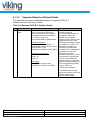
5.1.2 S.M.A.R.T. Command Set
The supported S.M.A.R.T. command set is listed in the table below. See the AT
Attachment standard for implementation details.
Table 5-3: S.M.A.R.T. Command Set
Value (hex) Command
00-CF
Reserved
D0
S.M.A.R.T. read attributes
D1*
S.M.A.R.T. read threshold
D2
S.M.A.R.T. enable/disable attribute autosave
D3*
S.M.A.R.T. save attribute values
D4
S.M.A.R.T. execute off-line immediate
D5
S.M.A.R.T. read log sector
D6
S.M.A.R.T. write log sector
D7*
S.M.A.R.T. write attribute threshold
D8
S.M.A.R.T. enable operations
D9
S.M.A.R.T. disable operations
DA
S.M.A.R.T. return status
DB
S.M.A.R.T. enable/disable automatic off-line
DC-FF
Reserved (Vendor Specific)
* Note that D1, D3, and D7 have been made obsolete in the
ATA-8 specification.
Datasheet
PSFEM2XXXGXXXX
Revision A2
www.vikingtechnology.com
06/04/2012
Viking Technology
Page 29 of 46
5.1.2.1
Off-line Mode
MSATA SSD’s support the optional 28-bit S.M.A.R.T. EXECUTION OFF-LINE
IMMEDIATE (B0h/D4h) command per the ATA-8 specification. This command
causes the MSATA SSD to initiate the collection of S.M.A.R.T. data in an off-line
mode and then preserves this data across power and reset events. Supported
subcommands include those shown in the table below. Reference the ATA-8
specification for subcommand detail.
Table 5-4: Supported S.M.A.R.T. EXECUTE OFF-LINE IMMEDIATE
Subcommands
Value
00h
01h
02h
04h
7Fh
81h
82h
84h
5.1.2.2
Description
Execute S.M.A.R.T. off-line routine immediately in off-line mode
Execute S.M.A.R.T. Short self-test routine immediately in off-line mode
Execute S.M.A.R.T. Extended self-test routine immediately in off-line mode
Execute S.M.A.R.T. Selective self-test routine immediately in off-line mode
Abort off-line mode self-test routine
Execute S.M.A.R.T. Short self-test routine immediately in captive mode
Execute S.M.A.R.T. Extended self-test routine immediately in captive
mode
Execute S.M.A.R.T. Selective self-test routine immediately in captive mode
Captive Mode
When executing a self-test in captive mode, MSATA SSD’s execute the self-test
routine after receipt of the command. At the end of the routine MSATA SSD’s
place the results of this routine in the self-test execution status byte and reports
command completion. If an error occurs while the MSATA SSD is performing the
routine it discontinues its testing, place the results of this routine in the self-test
execution status byte and the DST log page, and complete the command.
5.1.2.3
S.M.A.R.T. Logs
S.M.A.R.T. logs are intended to enhance S.M.A.R.T. Attribute information by
capturing additional drive details at appropriate times. This information may lead
to improved error detection and reporting capability. The controller supports
S.M.A.R.T. logs, and relevant tests, events, and conditions each have an
associated log. S.M.A.R.T. logs conform to industry-standard structures.
The reported size of each log is reported by the Log Directory (Log 0). Note that
the information returned via S.M.A.R.T. Read Log access to Log 0 is more limited
than that via GP Read Log. Log size is only reported the LSB (max 255 blocks)
Datasheet
PSFEM2XXXGXXXX
Revision A2
www.vikingtechnology.com
06/04/2012
Viking Technology
Page 30 of 46
when access via S.M.A.R.T. Read Log command; and full 2 bytes (max 65535
blocks) when access via Read Log EXT command.
The frequency at which S.M.A.R.T. logs are updated is the frequency at which
checkpoint information is saved. That frequency is related to data volume, and
can range between approximately 2 seconds and 2 minutes, depending on how
much data is being transferred. Therefore, constant host system IOs cause
check-pointing and S.M.A.R.T. log update relatively frequently (approximately
every 2 seconds); very slow or idle host transaction rates result in check-pointing
and S.M.A.R.T. log update less frequently (worst-case around every 2 minutes).
All logs are non-volatile except as within each of the log description.
Handling and reporting error conditions relating to the updating of S.M.A.R.T.
logs and S.M.A.R.T. Attributes is accomplished the same as handling error
conditions experienced while saving user data. Likewise, handling and reporting
error conditions relating to other processes (including background processes)
that occur while updating S.M.A.R.T. logs and S.M.A.R.T. Attributes is
accomplished the same as handling such error conditions while saving user data.
S.M.A.R.T. logs are validated by affecting the events being detected and logged;
the S.M.A.R.T. log always reflects the event that occurred, whether that event is
injected artificially or occurs independently.
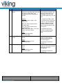
5.1.3 S.M.A.R.T. Attributes
5.1.3.1
Supported (Baseline) Attributes
The following table shows the supported S.M.A.R.T. attributes.
Table 5-5: Baseline S.M.A.R.T. Attribute Summary
ID
1
Hex
0x01
Attribute Name
Raw Read Error Rate
5
9
0x05
0x09
Retired Block Count
Power-On Hours (POH)
12
0x0C
Device Power Cycle Count
171
172
174
0xAB
0xAC
0xAE
Program Fail Count
Erase Fail Count
Unexpected Power Loss
Count
Datasheet
PSFEM2XXXGXXXX
Revision A2
www.vikingtechnology.com
Description
Raw error rate related to ECC errors.
Correctable and uncorrectable RAISE errors
are included in the error event count. (UECC
+ URAISE)
Tracks the total number of retired blocks.
Count of hours in power-on state. The raw
value of this attribute shows total count of
hours in power-on state.
This attribute indicates the count of full hard
disk power on/off cycles.
Counts the number of flash program failures
Counts the number of flash erase failures
Counts the number of unexpected power loss
events since the drive was deployed.
06/04/2012
Viking Technology
Page 31 of 46
ID
177
Hex
0xB1
Attribute Name
Wear Range Delta
181
182
187
0XB5
0XB6
0xBB
Program Fail Count
Erase Fail Count
Reported Uncorrectable
Errors
194
0xC2
Temperature
195
0xC3
ECC On the Fly Count
196
0xC4
Reallocation Count
201
0xC9
Uncorrectable Soft Read
Error Rate
204
0xCC
Soft ECC Correction Rate
231
0xE7
SSD Life Left
241
0xF1
Lifetime Writes from Host
242
0xF2
Lifetime Reads to Host
Notes:
1.
Description
Returns the percentage difference in wear
between the most worn block and the least
worn block.
(Identical to Attribute 171)
(Identical to Attribute 172)
This attribute tracks the number of
uncorrectable RAISE (URAISE) errors
reported back to the host for all data access
commands.
Temperature assuming an on-board sensor
connected via ISTW interface.
This attribute tracks the number of
uncorrectable errors (UECC).
This attribute tracks the # of blocks failing
programming which are reallocated.
Number of soft read errors that cannot be
fixed on-the-fly and requires deep recovery
via RAISE. (ie UECC)
Number of errors corrected by RAISE that
cannot be fixed on-the-fly and requires ECC
(multilevel) to correct. (ie UECC)
Indicates the approximate percentage of SSD
life left.
Indicates the total amount of data written from
hosts since the drive was deployed.
Indicates the total amount of data read to
hosts since the drive was deployed.
SMART ID# 233 and 234 are for Internal Use only.
Datasheet
PSFEM2XXXGXXXX
Revision A2
www.vikingtechnology.com
06/04/2012
Viking Technology
Page 32 of 46
5.1.3.2
Supported Baseline Attribute Details
The table below provides a detailed description of supported S.M.A.R.T.
attributes and how they may be used.
Table 5-6: Baseline S.M.A.R.T. Attribute Details
ID
1
Attribute Name
Raw Read Error
Rate
Description
Raw error rate related to ECC errors.
Errors are counted as ECC errors
above a threshold. For the controller,
this attribute includes Uncorrectable
ECC (UECC) errors, and
Uncorrectable RAISE (URAISE)errors.
Normalized Equation:
10log10(BitsRead/ReadErrors + 1)
SectorsRead= Number of sectors read
SectorsToBits= 512*8
BitsRead= SectorsRead*SectorsToBits
Normalized Value Range:
Best = 120
Worst = 38
Invalid = 0
Raw Usage:
[3-0] : Number of sectors read
[6-4]: Read errors (UECC+URAISE)
Rational
The Raw Read error rate
includes two types of
ECC errors that are tracked by
the controller: UECC and
URAISE. The normalized
equation for Raw read error rate
is logarithmic since the valid
BER range of the attribute spans
from 1.00E-10 to 1.00E-12. To
force positive numbers, the
numerator and denominator
are flipped. One is then added to
the number of errors in the
denominator to avoid a
divide-by-0 condition if no errors
are encountered. By taking the
log of the inverted BER and
multiplying by ten a reasonable
range of normalized values from
120 to 38 (representing a BER
range of 1.00E-13 to
1.68E-04 ) are presented.
This Attribute reads ‘0’ until a
sample size between 10E10 and
10E12 is available to be
tracked by this Attribute.
Datasheet
PSFEM2XXXGXXXX
Revision A2
www.vikingtechnology.com
06/04/2012
Viking Technology
Page 33 of 46
ID
5
Attribute Name
Retired Block
Count
Description
Tracks the total number of retired
blocks.
Normalized Equation:
Count = 100 - (100* RBC / MRB)
RBC = RetiredBlockCount = Number
of retired blocks.
MRB = MinimumReqBlocks =
Minimum number of reserve blocks
available for controller use. This
value is set at factory configuration
time.
Rational
The normalized equation for this
attribute decrements as blocks
are retired and the reserve
(over-provisioned) block count is
decremented. (Note that all
blocks, including reserve blocks,
are in service at all times;
reserve blocks constitute Flash
memory space over and above
the drive’s logical capacity.)
As defined, this attribute is
identical to the Reallocation
Event Count attribute (#196).
Normalized Value Range:
Best = 100
Worst = 0
Raw Usage:
[3-0] : Retired block count
[6-4] : None (0x00)
9
Power-On Hours
(POH)
Count of hours in power-on state. The
raw value of this attribute shows total
count of hours in the power-on state.
Normalized Equation: 100 - (POH /
HPY * 10)
The normalized equation for
Power-On hours decrements by
1 each 1/10 year. Note that
some manufacturers elect to
decrement by 1 for each 1/12
year of POH.
Normalized Value Range:
Best = 100
Worst = 0
Raw Usage:
[3-0] : Total number of power-on hours
[6-4]: total number of milliseconds
since last
hour update
Datasheet
PSFEM2XXXGXXXX
Revision A2
www.vikingtechnology.com
06/04/2012
Viking Technology
Page 34 of 46
ID
12
171
172
174
Attribute Name
Device Power
Cycle Count
Program Fail
Count
Erase Fail Count
Unexpected
Power Loss
Description
This attribute indicates the count of full
hard disk power on/off cycles.
Normalized Equation: 100 - (PCC /
1024)
Normalized Value Range:
Best = 100
Worst = 0
Raw Usage:
[3-0] : Cumulative lifetime power cycle
count (PCC)
[6-4] : None (0x00)
Counts the number of flash program
failures.
Rational
The normalized equation for
Power Cycle Count decrements
by 1 for each 1024 power
cycle.
This Attribute returns the total
number of Flash program
operation failures since the
drive was deployed.
Usage:
[3-0] : Program Error Count
[6-4] : None (0x00)
This Attribute is identical to
Attribute 181.
Counts the number of flash erase
failures.
This Attribute returns the total
number of Flash erase operation
failures since the drive
was deployed.
Usage:
[3-0] : Erase Error Count
[6-4] : None (0x00)
Counts the number of unexpected
power loss events, as determined by
the number of times PFAIL has been
asserted (or other criteria?).
This Attribute is identical to
Attribute 182.
This Attribute returns the total
number of unexpected power
loss events over the life of
the drive.
Usage:
[3-0] : Unexpected Power Loss Event
Count
[6-4] : None (0x00)
Datasheet
PSFEM2XXXGXXXX
Revision A2
www.vikingtechnology.com
06/04/2012
Viking Technology
Page 35 of 46
ID
177
Attribute Name
Wear Range
Delta
Description
Provides a value equal to the delta
between the max worn Flash block and
the least worn Flash block, as a
percentage of the max rated wear of
the SSD.
Rational
This Attribute identifies the
“delta” between most-worn and
least-worn Flash blocks, as a
percentage of the max rated
wear of the Flash memory on the
SSD.
Equation:
Wear Range Delta = [(MW - LW) /
MRW] x 100
For 10,000-cycle Flash, where
1% of rated cycles is 100 cycles,
a value of 1.5 for this Attribute
means the difference in wear
between the least worn block
and the most-worn block is 150
Erase cycles.
MW = P-E Cycles experienced by
Most Worn block
LW = P-E Cycles experienced by
Least Worn block
MRW = Max Rated Wear = P-E Cycle
rating for the Flash memory
181
Program Fail
Count
Usage:
[3-0] : Wear Range delta
[6-4] : None (0x00)
Counts the number of flash program
failures.
Usage:
[3-0] : Program Error Count
[6-4] : None (0x00)
182
Erase Fail Count
Counts the number of flash erase
failures.
Usage:
[3-0] : Erase Error Count
[6-4] : None (0x00)
Datasheet
PSFEM2XXXGXXXX
Revision A2
www.vikingtechnology.com
This attribute may not be
accurate until approximately
10% of drive life has been
used.
This Attribute returns the total
number of Flash program
operation failures since the
drive was deployed.
This Attribute is identical to
Attribute 171.
This Attribute returns the total
number of Flash erase operation
failures since the drive
was deployed.
This Attribute is identical to
Attribute 172.
06/04/2012
Viking Technology
Page 36 of 46
ID
187
Attribute Name
Reported
Uncorrectable
Errors (URAISE)
Description
Uncorrectable
Errors (URAISE)
This attribute tracks the number of
uncorrectable RAISE (URAISE) errors
reported back to the host for all data
access commands.
Normalized Equation: 100 - (URAISE)
Normalized Value Range:
Best = 100
Worst = 0
194
Temperature
Raw Usage:
[1-0] : Cumulative lifetime URAISE
errors
[6-2] : None (0x00)
Temperature of the SSD assembly.
That is,the temperature inside the SSD
housing.
Normalized Equation:
Temperature = Temperature (Celsius)
Normalized Value Range:
Best (lowest) = -127
Worst (highest) = 127
Raw Usage:
[1-0] : Current temperature (C; from
sensor)
[3-2]: Highest temperature (C; since
power-on)
[5-4]: Lowest temperature (C; since
power-on)
[6] : None (0x00)
Datasheet
PSFEM2XXXGXXXX
Revision A2
www.vikingtechnology.com
Rational
The uncorrectable ECC error
rate tracks the controller
Uncorrectable RAISE (URAISE)
errors. The normalized equation
for Uncorrectable Error Count
decrements by 1 for each
URAISE error. Uncorrectable
errors reported in this field are
uncorrectable by any level of
ECC protection including RAISE.
The normalized temperature is a
straight Celsius value as
obtained from the primary
SSD temperature sensor.
The raw values represent
current and historical Celsius
temperature values from the
primary SSD temperature
sensor.
For SSD designs incorporating
multiple temperature sensors,
current temperature is taken
from the sensor with the highest
reading; historical values are
highest or lowest of all sensors
polled.
06/04/2012
Viking Technology
Page 37 of 46
ID
195
Attribute Name
ECC On-the-Fly
Error Count
Description
This attribute tracks the number of
uncorrectable ECC errors (UECC). The
normalized value is only computed
when the number of bits in the
"BitsRead" count is in the range of
10^10 to 10^12. The count is cleared at
power on reset and when >10^12 bits
have been read.
Normalized Equation:
10log10(BitsRead/ECCOnTheFlyErrors
+ 1)
SectorsRead= Number of sectors read
SectorsToBits= 512*8
BitsRead= SectorsRead*SectorsToBits
Normalized Value Range:
Best = 120
Worst = 38
Invalid = 0
Raw Usage:
[3-0] : Number of sectors read
[6-4]: ECCOnTheFlyErrors (UECC)
count
Rational
The ECC On The Fly error rate
includes all uncorrectable ECC
errors (UECC) tracked by the
controller. The normalized
equation for ECC On The Fly
error rate is logarithmic since the
valid BER range of the attribute
spans from 1.00E-10 to 1.00E12. To force positive numbers,
the numerator and denominator
are flipped. One is then added to
the number of errors in the
denominator to avoid a divideby-0 condition if no errors are
encountered. By taking the log of
the inverted BER and multiplying
by ten a reasonable range of
normalized values from 120 to
38 (representing a BER range of
1.00E-13 to 1.68E-04 ) are
presented. As defined, this
Attribute is identical to Attribute
201 and Attribute 204.
This Attribute reads ‘0’ until a
sample size between 10E10 and
10E12 is available to be tracked
by this Attribute.
Note that many UECC errors
counted by this Attribute are
corrected by RAISE correction.
Datasheet
PSFEM2XXXGXXXX
Revision A2
www.vikingtechnology.com
06/04/2012
Viking Technology
Page 38 of 46
ID
196
Attribute Name
Reallocation
Event Count
Description
Tracks the total number of reallocated
Flash blocks.
Normalized Equation:
Count = 100 - (100* RBC / MRB)
RBC = RetiredBlockCount = Number
of retired blocks.
MRB = MinimumReqBlocks =
Minimum number of reserve blocks
available for contoller use. This value is
set at factory configuration time.
Rational
The normalized equation for this
attribute decrements as blocks
are retired and the reserve
(over-provisioned) block count is
decremented. (Note that all
blocks, including reserve blocks,
are in service at all times;
reserve blocks constitute Flash
memory space over and above
the drive’s logical capacity.)
As defined, this attribute is
identical to the Retired Block
Count attribute (#5).
Normalized Value Range:
Best = 100
Worst = 0
Raw Usage:
[3-0] : Retired block count
[6-4] : None (0x00)
Datasheet
PSFEM2XXXGXXXX
Revision A2
www.vikingtechnology.com
06/04/2012
Viking Technology
Page 39 of 46
ID
201
Attribute Name
Uncorrectable
Soft Read Error
(UECC)
Description
Number of soft read errors that cannot
be fixed on-the-fly and requires deep
recovery provided by RAISE. The
normalized value is only computed
when the number of bits in the
"BitsRead" count is in the range of
10^10 to 10^12. The count is cleared at
power on reset and when >10^12 bits
have been read.
Normalized Equation:
10log10(BitsRead/UECC + 1)
SectorsRead= Number of sectors read
SectorsToBits= 512*8
BitsRead= SectorsRead*SectorsToBits
Normalized Value Range:
Best = 120
Worst = 38
Invalid = 0
Raw Usage:
[3-0] : Number of sectors read
[6-4]: Uncorrectable Soft error count
(UECC)
Rational
The Uncorrectable Soft Read
Error Rate includes all
uncorrectable ECC (UECC)
errors tracked by the
CONTROLLER. The normalized
equation for Uncorrectable Soft
Read Error Rate is logarithmic
since the valid BER range
of the attribute spans from
1.00E-10 to 1.00E-12. To force
positive numbers, the numerator
and denominator are flipped.
One is then added to the number
of errors in the denominator to
avoid a divide-by-0 condition
if no errors are encountered. By
taking the log of the inverted
BER and multiplying by ten a
reasonable range of normalized
values from 120 to 38
(representing a BER range of
1.00E-13 to 1.68E-04 ) are
presented. As defined this
attribute is identical to 195 and
204.
This Attribute reads ‘0’ until a
sample size between 10E10 and
10E12 is available to be tracked
by this Attribute.
Datasheet
PSFEM2XXXGXXXX
Revision A2
www.vikingtechnology.com
06/04/2012
Viking Technology
Page 40 of 46
ID
204
Attribute Name
Soft ECC
Correction Rate
(UECC)
Description
Number of errors corrected by RAISE
that cannot be fixed on-the-fly and
requires RAISE to correct. The
normalized value is only computed
when the number of bits in the
"BitsRead" count is in the range of
10^10 to 10^12. The count is cleared at
power on reset and when >10^12 bits
have been read.
Normalized Equation:
10log10(BitsRead/UECC + 1)
SectorsRead= Number of sectors read
SectorsToBits= 512*8
BitsRead= SectorsRead*SectorsToBits
Normalized Value Range:
Best = 120
Worst = 38
Invalid = 0
Raw Usage:
[3-0] : Number of sectors read
[6-4]: Soft ECC correction count
(UECC)
231
SSD Life Left
Indicates the approximate SSD life left,
in terms of PE cycles and Flash blocks
currently available for use.
Normalized Equation:
SSD Life Left = MIN[ MAX(termA, 10),
termB]
termA = (Unused)/(Rated) x 100
Unused = (unused PE cycles)
Rated = (rated PE cycles)
termB = (AvailExcess)/(OrigExcess)
AvailX = (Blocks above min req’d)
OrigX = (Original blks above min
req’d)
Normalized Value Range:
100 = Best = Full SSD life remains
10 = Replace = Sufficient Flash blocks
still in service, but rated PE Cycles
consumed
0 = Worst = Insufficient Flash blocks
remain in service; EOL; drive is readonly
Datasheet
PSFEM2XXXGXXXX
Revision A2
www.vikingtechnology.com
Rational
The Soft ECC Correction Rate
includes all uncorrectable ECC
(UECC) errors tracked by
the CONTROLLER. The
normalized equation for Soft
ECC Correction Rate is
logarithmic since the
valid BER range of the attribute
spans from 1.00E-10 to 1.00E12. To force positive numbers,
the numerator and denominator
are flipped. One is then added to
the number of errors in the
denominator to avoid a divideby-0 condition if no errors are
encountered. By taking the log of
the inverted BER and multiplying
by ten a reasonable range of
normalized values from 120 to
38 (representing a BER range of
1.00E-13 to 1.68E-04 ) are
presented. As defined this
attribute is identical to 195 and
201.
This Attribute reads ‘0’ until a
sample size between 10E10 and
10E12 is available to be tracked
by this Attribute.
SSD life left is based on actual
usage and takes into account PE
cycle consumption and Flash
block retirement.
PE cycle usage at a rate less
than the rate used for
performance throttling will result
in extending drive life. Actual
Flash endurance remaining is
normally greater than the
unused rated PE cycles.
Note that block retirement rate
also affects SSD life and this
Attribute value.
06/04/2012
Viking Technology
Page 41 of 46
ID
241
Attribute Name
Lifetime Writes
from Host
System
Description
Indicates the number of bytes (in 64GB
resolution) written to the drive by a host
system, over the life of the drive.
Usage:
[3-0]: Count of 64GB units written
[6-4] : None (0x00)
242
Lifetime Reads to
Host System
Indicates the number of bytes (in 64GB
resolution) read from the drive by a
host system, over the life of the drive.
Usage:
[3-0]: Count of 64GB units read
[6-4] : None (0x00)
Rational
This Attribute returns a byte
count, in units of Gigabytes at an
update resolution of 64 GBytes.
The count represents the
number of bytes written. The
Attribute reads ‘0’ until the
number of bytes written reaches
64GB; at 64GB the Attribute
increments to a value of
‘64’ (decimal).
This Attribute returns a byte
count, in units of Gigabytes at an
update resolution of 64 GB.
The count represents the
number of bytes read. The
Attribute reads ‘0’ until the
number of bytes read reaches
64GB; at 64GB the count
increments to a value of ‘64’
(decimal).
Figure 5-1: S.M.A.R.T. ECC and RAISE Error Summary
Datasheet
PSFEM2XXXGXXXX
Revision A2
www.vikingtechnology.com
06/04/2012
Viking Technology
Page 42 of 46
5.1.4 Attribute Sector
The S.M.A.R.T. Attribute Sector defines attribute format and the data structure is
defined in the following table.
Table 5-7: S.M.A.R.T. Attribute Data Structure
Byte
Description
0:1
2
3:4
5
6
7:12
13
14:25
S.M.A.R.T. structure version number
First Stored Attribute Number (i.e. “1” for RawErrorRate)
Status
Nominal value
Worst value since SSD was deployed
Raw Data
Reserved
Next Stored Attribute Number (ie “3” for “Retired Block Count”)
Next Stored Attribute Numbers (max 30 collected Attributes, including
above)
Off-line data collection status
Self-test execution status byte
Total time to complete off-line data collection (in seconds)
Reserved
Off-line Data Collection capability
S.M.A.R.T. capability
Error Logging Capability (bit 0 set = device error logging supported)
Next Self Test Step
Short Self Test routine recommended polling time (in minutes)
Extended Self Test routine recommended polling time (in minutes)
Recommended polling time for Conveyance Self Test
Time for Extended Self Test if > 255 (ie, 373 to FFh)
Reserved
Vendor Information
Checksum of data structure (generated on retrieval of stored data)
26:361
362
363
364:365
366
367
368:369
370
371
372
373
374
375:376
377:385
386:510
511
Note: Bytes 2:361 are vendor unique
5.1.5 Threshold Sector
The S.M.A.R.T. Threshold Sector defines attribute trip thresholds. Attributes are
compared to the thresholds when the S.M.A.R.T. Return Status Command (DA)
retrieves drive reliability Status. The S.M.A.R.T. Read Threshold Sector
Command (DI) then used to read this information. Threshold information may be
modified or written via the S.M.A.R.T. Write Threshold Value Command (D7).
Threshold values are obtained from the Saved Configuration Page.
Datasheet
PSFEM2XXXGXXXX
Revision A2
www.vikingtechnology.com
06/04/2012
Viking Technology
Page 43 of 46
Table 5-8: S.M.A.R.T. Threshold Data Structure
Byte
Description
0:1
2
3
4:13
14
15
16:25
S.M.A.R.T. structure version number
First Stored Attribute Number (i.e. “1” for RawErrorRate)
Threshold Value for first attribute
Reserved
Next Stored Attribute Number
Threshold Value for next attribute
Reserved
Attribute Number, Threshold and 10 reserved bytes for supported
attributes, (max 30 collected Attributes, including above)
Reserved
Vendor Unique
Checksum
26:361
362:379
380:510
511
5.1.6 S.M.A.R.T. Command Transport (SCT)
MSATA SSD’s support the S.M.A.R.T. Command Transport (SCT). SCT allows
the host to send commands, send and receive data, and receive status to and
from the MSATA SSD using log page 0xE0 and log page 0xE1. SCT uses
S.M.A.R.T. READ/WRITE LOG commands, READ/WRITE LOG EXT commands,
or READ/WRITE LOG DMA EXT commands to access the log pages. For
additional SCT information please reference ATA8-ACS.
5.2 SATA Commands
The SATA 3.0 specification is a super set of the ATA/ATAPI-7 specification with
regard to supported commands. MSATA SSD’s support the following features
that are unique to the SATA specification.
5.2.1 Native Command Queuing (NCQ)
MSATA SSD’s support the Native Command Queuing (NCQ) command set,
which consists of
READ FPDMA QUEUED
WRITE FPDMA QUEUED
Note: With a maximum queue depth less than or equal to 32.
Datasheet
PSFEM2XXXGXXXX
Revision A2
www.vikingtechnology.com
06/04/2012
Viking Technology
Page 44 of 46
6 Certifications and Compliance
Table 6-1: Device Certifications
Certification/Compliance
RoHS
China RoHS
Serial ATA
EU WEEE Compliant
Description
Viking Modular Solutions(TM), Sanmina-SCI Corporation ("Viking")
shall use commercially reasonable efforts to provide components,
parts, materials, products and processes to customers that do not
contain: (i) lead, mercury, hexavalent chromium, polybrominated
biphenyls (PBB) and polybrominated diphenyl ethers (PBDE) above
0.1% by weight in homogeneous material or (ii) cadmium above
0.01% by weight of homogeneous material, except as provided in any
exemption(s) from RoHS requirements (including the most current
version of the "Annex" to Directive\ 2002/95/EC of 27 January, 2003),
as codified in the specific laws of the EU member countries. Viking
strives to obtain appropriate contractual protections from its suppliers
in connection with the RoHS Directives.
Restriction of hazardous substances
Requirements for logo
The Waste Electrical and Electronic Equipment Directive (WEEE
Directive) is the European Community directive 2002/96/EC on waste
electrical and electronic equipment (WEEE) which, together with the
RoHS Directive 2002/95/EC, became European Law in February
2003, setting collection, recycling and recovery targets for all types of
electrical goods.
7 References
JEDEC Mechanical Outline MO-300
Environmental Specification: MIL-STD-810F
Amphenol SATA Connector, mini PCI Express (mini PCIe)
Serial ATA Specification, revision 3.0
Datasheet
PSFEM2XXXGXXXX
Revision A2
www.vikingtechnology.com
06/04/2012
Viking Technology
Page 45 of 46
8 Glossary
This document incorporates many industry- and device-specific words. Use the
following list to define a variety of terms and acronyms.
Term
ATA
ATAPI
BER
DIPM
DMA
eMLC
EXT
FP
GB
HDD
Hot Plug
IOPS
LBA
MB
MLC
MTBF
NCQ
NOP
OS
Port
RMS
RPM
SAS
SATA
SFF
SLC
S.M.A.R.T.
SSD
Datasheet
PSFEM2XXXGXXXX
Revision A2
www.vikingtechnology.com
Definition
Advanced Technology Attachment
Advanced Technology Attachment Packet Interface
Bit error rate, or percentage of bits that have errors relative to the total number of bits
received
Device Initiated Link Power Management. The ability of the device to request SATA link
power state changes.
Direct Memory Access
Enterprise Multi-Level Cell
Extended
First Party
Giga-byte defined as 1x109 bytes
Hard Disk Drive
A term used to describe the removal or insertion of a SATA storage drive when the
system is powered on.
Input output operations per second
Logical Block Address
Mega-bytes defined as 1x106 bytes
Multi-Level Cell
Mean Time Between Failures
Native Command Queuing. The ability of the SATA hard drive to queue and re-order
commands to maximize execution efficiency.
No Operation
Operating System
The point at which a SATA drive physically connects to the SATA controller.
Root Mean Squared
Revolutions Per Minute
Serial Attached SCSI
Serial ATA
Small Form Factor
Single Level Cell
Self-Monitoring, Analysis and Reporting Technology: an open standard for developing
hard drives and software systems that automatically monitors a hard drive’s health and
reports potential problems.
Solid-State Drive
06/04/2012
Viking Technology
Page 46 of 46