1
SAVE THIS MANUAL
FOR FUTURE =
REFERENCE
BELT AND DISC
SAN DER
Serial
Number.
Model and serial
number may be found on
the back side of
the base.
You should record both
model and serial number
in a safe place for
future use.
TA
SANDER
CAUTmON:
® assembly
• operating
• repair parts
Read GENERAL and
ADDITIONAL
SAFETY
INSTRUCTIONS
carefully
Sold by SEARS,
Part No, SP4916
DISC
ROEBUCK
AND
CO., Chicago,
IL. 60684 U.S.A.
WARRANTY SERVICE IS AVAILABLE BY SIMPLY CONTACTING THE NEAREST SEARS SERVICE
CENTERiDEPARTMENT
TH ROU G HOUT TH E UNITED STATES.
THIS WARRANTY APPLIES ONLY WHILE THIS: PRODUCT IS USED IN THE UNITED STATES.
This warranty gives you specific legal rights, and you may also have other rights which vary from
state to state.
SEARS,
ROEBUCK AND CO., 6981731A, Sears Tower, Chicago,
IL 60684
enerai safety:ansi uctions for power tools
.
I.
2.
J
r
Z87,1) at all times,
Everyday
eyeglasses
only
have impact
resistant
lenses,
they are NOT
safety glasses,
Also, use face or dust mask if
cutting
operation
is dusty, and ear protectors
(plugs or muffs)
during
extended
periods
of
operation.
KNOW :YOUR :POWER TOOL
Read and understand:the:
owner's
manual and
labels affixedlto
the toot. Learn its application
and Limitations;as
we i ks: the speCifiC potential
hazards peculiar to this tool.
GROUND ALL tOOLS
This tool
is equipped:with
an approved
3conductor
cord and ai3;prong
grounding
type
plug to fit: the proper grounding
type receptacle.
The green conductor
in the cord is the grounding wire, Never connect the green wire to a live
terminal:
13. SECURE WORK
Use clamps or a vise to hold work when practical, It's safer than using your hand. frees both
hands to operate tool,
14. DON'T OVERREACH
Keep proper footing and balance at a_l times.
15. MAINTAIN TOOLS WITH CARE
Keep tools sharp and clean for best and safest
performance.
Follow instructions
for lubricating
and changing accessories,
16. DISCONNECT
TOOLS
before
servicing;
when changing
accessories
such as blades, bits, cutters, etc,
3,
....
KEEP GUARDS IN PLACE
:- in working
order, and in proper adjustment
and alignment_
4.: REMOVE ADJUSTING KEYS AND WRENCHES
Form a habit of checking
adjusting
wrenches
are
before turning
it on.
5,
to see that keys and
removed
from
tool
KEEP WORK AREA CLEAN
Cluttered
areas and benches
invite accidents.
Floor _must not be slippery
due to wax or sawdust,
17. AVOID ACCIDENTAL
STARTING
Make sure switch
is in "OFF"
plugging
n.
9.
MAKE WORKSHOP
with padlocks,
CHILD-PROOF
master
switches,
moving starter keys.
DON'T FORCE TOOL
It will do the job better
which it was designed.
and safer
or
by
before
18. USE RECOMMENDED
ACCESSORIES
Consult the owner's
manual for recommended
accessories.
Follow
the
instructions
that
accompany
the accessories.
The use of improper accessories
may cause hazards.
6_ AVOID DANGEROUS: ENVIRONMENT
Don't use,power
tools in damp or Wet locations
or expose them te rain, Keep work area weii
lighted.
Provide
adequate
surrounding
work
space.
7. KEEP CHILDREN: AWAY
All visitors should be kept a safe distance
from
work area,
8.
position
19; NEVER STAND ON TOOL
Serious injury could occur if the tool is tipped
Or if the cutting tool is accidentally
contacted
Do not store materials
above or near the toof
such that it is necessary
to stand on the tool to
reach them.
re-
20, CHECK DAMAGED PARTS
Before further use of the tool, a guard or other
part that is damaged should be carefully
checked to ensure that it will operate properly
and
perform its intended
function.
Check for alignment of moving parts, binding
of moving parts,
breakage of parts, mounting, and any other conditions that may affect its operation.
A guard or
other part that is damaged
should be properly
repaired or replaced.
at the rate for
10. USE RIGHT TOOL
Don't force tool or attachment
to do a job it was
not designed
for.
11. WEAR PROPER APPAREL
Do not wear loose clothing,
gloves, neckties
or
jewelry
(rings, wristwatches)
to get caught
=n
moving
parts,
NONSLIP
footwear
is recommended. Wear protective
hair covering
to contain long hair. Roll long sleeves
above
the
elbow.
!2; USE SAFETY GOGGLES (Head Protection)
Wear safety goggles
(must comply
with ANSi
21, DIRECTION OF FEED
Feed work into a blade or cutter against
the
direction of rotation of the blade or cutter only.
22. NEVER LEAVE TOOL RUNNING UNATTENDED
Turn power off, Don't leave tool until it comes
to a complete
stop.
2
ad
safety instructions
diSC sander
Safety is a combination
of operator
common
sense and alertness at alt times when the sander
is being used.
f. Make sure the sanding belt runs in the
right direction
(directional
arrow on back
side of belt). Always have the tracking
adjusted correctly
so that the belt does
not run off the pulleys.
g. Hold the work firmly when sanding on the
belt and against the worktable when sanding
on the disc.
h. Always adjust the worktable
to within a
maximum of 1/16-inch of the sanding disc
or belt.
i. When sanding a large piece of material,
provide additional support at table height.
j. Never leave the machine work area when
the power is on, before the machine has
come to a complete stop, or without
removing and storing the switch key.
k. Do not perform layout, assembly or setup
work on the table while the sander is
operating.
I. Turn sander "OFF" and remove plug from
power supply outlet before installing
or
removing an accessory.
m.Use only RECOMMENDED
ACCESSORIES
listed on page 17,
WARNING: FOR YOUR OWN SAFETY, DO NOT
ATTEMPT
TO OPERATE
YOUR
BELT AND
DISC SANDER
UNTIL
IT IS COMPLETELY
ASSEMBLED AND INSTALLED ACCORDING TO
THE INSTRUCTIONS
... AND UNTIL YOU HAVE
READ AND UNDERSTOOD THE FOLLOWING:
1.
2,
3.
4,
PAGE
General Safety Instructions For Power Tools. 2
Getting To Know Your Sander ..............
11
Basic Operation ...........................
13
Maintenance ..............................
16
5. Stability Of Machine
If there is any tendency for the machine to tip
over or move during certain operations
such
as when sanding
tong heavy boards, the
sander should be bolted down.
w
,
,
Location
The machine should be positioned so neither
the operator nor a casual observer is forced
to stand in line with the sanding belt or disc.
This machine is intended for indoor use only.
Kickback
When sanding on the Disc, always apply the
workpiece left of center to the left side of the
disc. Applying the workpiece to the right side
could cause it to fly up (kickback) which
could be hazardous.
Protection: Eyes, Hands, Face, Hears, Body
a. Always wear safety goggles (not glasses)
that comply with ANSI Z87.1, Wear face
shield if operation is dusty. Wear ear plugs
or muffs during extended periods of operation. Do not wear gloves, jewelry or watches. Roll long sleeves above the elbow. Tie
back long hair.
b. Do not sand pieces of material too small
to hold by hand.
c. Avoid awkward
hand positions,
where a
sudden slip could cause a hand to move
into the sanding disc or belt.
d. Never climb on the machine.
e. Never turn your Sander "ON" before clearing the belt table and worktable of all ob_
jects.
for bett and
g,
If any part of this belt and disc sander should
break, bend, or fail in any way or any electrical component
fail to perform properly, or if
any is missing,
shut off power switch,
remove power supply cord from power supply
and replace damaged missing andtor failed
parts before resuming operation.
10. Do not sand with the workpiece unsupported.
Support it with the backstop
or worktable.
The only exception is curved work performed
on outer end of belt (idler pultey).
11. To avoid entanglement
in spindle, do not
operate sander with sanding
plate and or
guard removed.
CAUTION: This Belt and Disc Sander is designed
to sand wood or wood like products only.
Attempts to sand or grind other materials could
result in fire, injury or damage to the product.
disc
12: Think :Safety
....:Safety is a combination
of operator common
:sense and alterness: at all times when the
sander is in operation.
WEAR YOUR
I
The operation of any power t0ol can result in foreign objects be{rig thrown into the eyes, which
can result in severe eye damage, Always wear
safety
goggles
(not glasses)
complying
with
ANSI Z87,1 (shown on Package) before beginning
power tool operation.
Safety Goggies are available at Sears retail or catalog stores.
J'= 11
WARNING:DO
NOT ALLOW FAMILIARITY (GAINED FROM FREQUENT
BECOME COMMONPLACE.
ALWAYS REMEMBER THAT A CARELESS
SUFFICIENT TO INFLICT SEVERE INJURY.
READ AND
FOLLOW
THE WARNINGS
II
I II
.
i!
THAT
!!JL
I
IIIIII
11,,
i
_....
USE OF YOUR MACHINE) TO
FRACTION OF A SECOND IS
APPEAR ON THE TOOL:
I
I
I
I
I
...................
!Ill
FOR YOUR OWN SAFETY:
1. READ AND UNDERSTAND OWNER'S MANUAL
BEFORE OPERATING MACHINE.
2. WEAR SAFETY GOGGLES AND DUST MASK,
3, MAINTAIN 1/16"MAXIMUM CLEARANCE BETWEEN
: TABLE AND SANDING BELT OR DISC.
:::
4. AVOID"KICKBACK" (WORKPiECE THROWNAT
YOU)--DO NOT USE RIGHT HALF OF DISC.
_?\
5, ALWAYSSUPPORT WORKPIECE WITH "BACKSTOP" OR "WORKTABLE."
6. DO NOTWEAR GLOVES, NECKTIE OR LOOSE
CLOTHING.TIE BACK LONG HAtR.
4
'"
an emectricam
mot0r specifications
requirements ....
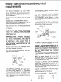
This machine is designed to use, and is equipped with, a 3450 RPM motor. It is wired for operation on 110-120 volts, 60 Hz., alternating
current.
(TOOL MUST NOT BE CONVERTED TO OPERATE ON 230 VOLT).
For replacement
manual.
motor
refer to parts list in this
CONNECTING TO POWER SUPPLY OUTLET
This machine must be grounded while in use to
protect the operator from electric shock.
Plug power cord ,into a 110-120V properly grounded type outlet protected by a 15-amp. fuse or circuit breaker.
WARNING:
DO NOT PERMIT
FINGERS
TO
TOUCH THE TERMINALS
OF PLUGS WHEN
INSTALLING OR REMOVING THE PLUG TO OR
FROM THE OUTLET,
WARNING:
IF NOT PROPERLY
GROUNDED
THIS POWER TOOL CAN CAUSE AN ELECTRICAL SHOCK PARTICULARLY WHEN USED IN
DAMP LOCATIONS CLOSE TO PLUMBING.
IF
AN ELECTRICAL
SHOCK OCCURS THERE IS
THE POTENTIAL OF A SECONDARY HAZARD
SUCH AS YOUR HANDS CONTACTING
THE
SANDING SURFACE,
If power cord is worn or cut, or damaged
way, have it replaced immediately.
Your unit is for use on 110420
plug that looks like below.
in any
volts, and has a
fi
3-PRONG
PLUG
\
)UNDING
PRONG
PROPERLY
GROUNDED
3-PRONGOUTLET
This power tool is equipped with a 3-conductor
cord and grounding
type plug which
has a
grounding
prong,
approved
by Underwriters'
Laboratories and the Canadian Standards Association. The ground conductor
has a green jacket
and is attached to the tool housing at one end
and to the ground prong in the attachment
plug
at the other end.
This plug requires a mating
ed type outlet as shown.
3-conductor
ground-
if the outlet you are planning to use for this
power tool is of the two prong type, DO NOT
REMOVE OR ALTER THE GROUNDING
PRONG
IN ANY MANNER.
Use an adapter as shown
below and always connect the grounding lug to a
known ground.
It is recommended
that you have a qualified electrician replace the TWO prong outlet with a properly grounded THREE prong outlet.
GROUNDINGLUG
SCREW
3-PRONG
PLUG
MAKE SURE TH_S!S
CONNECTED TO A
KNOWN GROUND
2-PRONG
RECEPTACLE
\
ADAPTER
An adapter as illustrated
ing plugs to 2-prong
is available
receptacles.
for connect-
WARNING: THE GREEN GROUNDING LUG EXTENDING FROM THE ADAPTER MUST BE CONNECTED TO A PERMANENT GROUND SUCH AS
TO A PROPERLY GROUNDED
OUTLET BOX.
NOT ALL OUTLET BOXES ARE PROPERLY
GROUNDED.
tf you are not sure that your outlet box is properly grounded, have it checked by a qualified electrician.
NOTE: The adapter illustrated
is for use only if
you already have a properly grounded
2-prong
receptacle, Adapter is not allowed in Canada by
the Canadian Electrical Code.
The use of any extension cord will cause some
loss of power. To keep this to a minimum and to
prevent overheating and motor burn-out, use the
table below to determine the minimum wire size
(A.W.G.) extension cord.
Use only 3 wire extension cords which have 3prong grounding
type plugs and 3-prong receptacles which accept the tools plug.
Extension
Cord Length
Up to 100 Ft.
100. 200 Ft.
200 _ 400 Ft.
Wire Size A.W.G.
16
14
!0
Fo
ADI
t BE
tiN
Mounting Seltand
To Woi'kbench
Disc Sander
.: ,, ;:. : ; . ..................
Clamping Belt And Disc Sander
To WOrkbench. ..............................
Installing Timing BeiL ............:
......
Installing
Installing
Installing
Installing
7
7
:.. 8
i...
Pulley Cover ........................
Sanding Disc Plate ..................
Backstop ...........................
Table Assembly ....................
;9
9
10
t0
Squaring Table:Assembly; .......................
Replacing The Sanding Belt
TensioningAnd
Tracking _i....
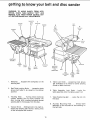
GETTING TO KNOW YOUR BELT AND
DISC SAN DER...i
_,,, ; ...................
Bevel Sanding ................................
Positioning Belt Table. .......................
Belt Table Stop ..............................
Surface Sanding On
Sanding Belt; ...............................
End Sanding On The
Sanding Belt ................................
Sanding Curved Edges .......................
MAINTENANCE ..............................
Lubrication ..................................
TROUBLESHOOTING
........................
R ECOMMENDED ACCESSORIES .............
R EPAIR PARTS ..............................
11
.12
13
15
15
16
16
16
17
18
18
19
19
20
unpacking and checking contents
TOOLS NEEDED
7t16" WRENCH
1/2" WRENCH
3/4" WRENCH
..................
Separate all parts from packing materials
and
check each item with illustration and "Table of
Loose Parts." Make certain all items are accounted for, before discarding any packing material.
COMBINATIONSQUARE
COMBINATIONSQUAREMUST BE TRUE
PHILLIPSTYPE
SCREWDRIVER
Model t13.226421 Belt and Disc Sander is shipped complete in one carton.
._":_.
.,"STRAIGHTEDGEOF
BOARD3/4 f THICK
THIS EDGEMUST BE
PERFECTLY:
STRAtGHT
ALONG:THISEDGE
SHOULD BENOGAPOR OVERLAPHEREWHEN
SQUARE_SFLtPPEDOVER N DOTTEDPOSITION
If any parts are missing,
do not attempt
to
assemble the Belt and Disc Sander, plug in the
power cord, or turn the switch on until the missing parts are obtained and installed correctly.
WARNING: FOR YOUR OWN SAFETY, NEVER
CONNECT PLUG TO POWER SOURCE OUTLET
UNTIL ALL ASSEMBLY STEPS ARE COMPLETE
AND UNTIL YOU HAVE READ AND UNDERSTOOD THE ENTIRE OWNERS MANUAL,
J_
ITEM
A
B
C
D
E
F
G
B
t
c
D
G
H
J
TABLE OF LOOSE PARTS
Belt and Disc Sander
.........
Assembly
Owners Manual.
Table Assembly
................
Sanding Plate ..................
Sanding Disc ...................
Table Support Rod ..............
Bag Assembly Part #507303
Containing the following parts:
Switch, Key ....................
Wrench, Hex "L" 118 ............
Backstop ........................
:Washer, 114". ...................
Bolt, Hex 1!4-20XLI2 .............
Bolt, Hex 5/16-t8X3/4 ...........
Knob ...........................
Setscrew 1/4-20X1/4". ...........
Screw 114-20X1-3/4". ............
Pulley Cover ....................
Timing Belt .....................
QTY.
1
1
1
1
1
1
,
1
1
!
1
1
1
1
1
1
1
1
8ssem
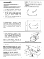
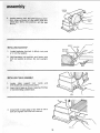
MOUNTING BELT AND
WORKBENCH
If belt and disc sander
nent location, it should
firm supporting surface
Drill (4) 318" diameter
bench.
.
y
4.
DISC SANDER TO
is to be used in a permabe fastened securely to a
such as a workbench.
,
Insert all four 5116" screws
,
-_
belt
(4) HOLES
1
and
_'_
An alternate
method of mounting
is to fasten
belt and disc sander to a mounting
board. The
board should be of sufficient
size to avoid tipping of sander while in use. Any good grade of
plywood or chipboard with a 3t4" minimum thickness is recommended.
(Thinner chipboard
can
break.)
,
24"
T+5-7t16
Follow
instructions
for mounting
to workbench, substituting
a board 18" x 24" minimum size and using 5t16 inch flat head
screws, Iockwashers,
and hex nuts (not included). Screw length should be 11/2" plus
the thickness of the mounting board.
NOTE: For proper
stability,
holes
must be
counter sunk so screw heads are flush with the
bottom surface of supporting
board.
MOUNTINGHOLES
IB
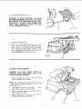
2,
Securely clamp
"C" clamps.
board
to workbench
and tighten.
3/8 " DIAMETE//R'_R
+
5-7/16 "
Each leg should be bolted securely using
5/16" hex nuts (not included). Screw length
should be 11/2" plus the thickness
of the
bench top.
Locate and mark the holes where
disc sander is to be mounted.
:'
PIll
JIl'
using
NOTE: Supporting
surface where belt and disc
sander is mounted should be examined carefully
after mounting to insure that no movement during use can result. If any tipping or walking is
noted, secure workbench
or supporting
surface
before operating belt and disc sander.
CLAMPING BELT AND DISC SANDER TO
WORKBENCH
The Belt and Disc Sander can be clamped directly to a workbench
using two (2) or more "C"
clamps on base of unit (one clamp on each end
of unit).
work,
_
Place belt and disc sander on workbench
aligning
holes in feet with holes drilled in
workbench.
If mounting
to a workbench,
holes should be
drilled through supporting
surface of the workbench using dimensions
illustrated.
.
holes through
MOUNrlNG
HOLES
WORKBENCH
CLAMP
"
318"
MIN,
...-*
DIAMETER (4) HOLES
LOCKING BOLTS
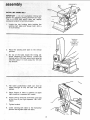
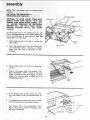
INSTALLING:!TIMING BELT :::
::: : : , :_ '!::::::::: :.::_:
IMPORTANT
Do:i:not::::::Ov:ertighten::
tim ing belt
tension by:adjusting,timing
setscrew too tight_
This ::iS: a i COG_:: Bel{ ::which:i:does
not require
excessiVe:tensionl
to function properly:
1. :Locate the two locking
bolts
sanding
belt: table and loosen
1/2inch wrench.
i
holding
the
both with a
.........
TIMING BELT
TENSION
ADJUSTMENT SET
SCREWAND
LOCKINGNUT
2, Raise
the sanding
position,
;
belt
table
to the vertical
On top of the base locate :the timing setscrew centered
in the locknut,
loosen the
Iocknut with a 7/16 inch wrench and raisethe
setscrew about t/4 inch using the 1t8 inch
hex wrench.
"'
,
.
.
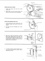
7.
.
,:H
The lower pulley/motor
raised enough to slip
pulleys,
Place fingers
light pressure
shaft can now: be
the belt over both
of hand in position
to apply
to squeeze belt inward.
Adjust timing setscrew downward until belt
is just firm to your light squeeze - BUT NOT
TIGHT.
Tighten
Iocknut.
Lower sanding belt table to the horizontal
position and tighten table lock bolts,
ji
PULLEY COVER
INSTALLING
1.
,
PULLEY COVER
Locate
the
114-20xl-3f4".
pulley
cover
and
one
screw
Place pulley cover into position shown and
fasten with one screw. Do not overtighten.
SCREW 1/4-20X1-3/4
INSTALLING
SANDING
DISC PLATE
HEXWRENCH
1.
Locate sanding disc plate, sanding disc, one
setscrew 1/4-20xl/4 inch, and a 1/8 inch hex
wrench.
2.
Just start screw
ing plate.
into threaded
hole in sand-
SANDING DiSC
....
, ......................
!!==!t
II
,.
_
Iqll
..........
,,
SANDING
DRIVE
,
']
Align flat on shaft with setscrew in sanding
plate. Slide sanding plate onto shaft until
plate surface and shaft are nearly flush. Do
not allow shaft to extend out past surface of
sanding plate or damage may occur to your
sanding disc during operation.
SHAFT
i
i1,1
FLAT .1-..
(ON SHAFT)
PLATE
//_,¢
I
SANDING
PLATE
GUARDNOT
SHOWNFOR
CLARITY
HEX
ENCH
.
To tighten setscrew,
reach through
top of pulley cover with hex wrench.
setscrew very firmly.
hole in
Tighten
SECTION OF
PULLEY COVER
REMOVED FOR
PICTURE CLAR;TY
9
SANDING
PLATE
i into
INSTALLING
the ::way
BACKSTOP
1_ Locate backstop, hex bolt 1/4-20xVz
a 1/4 inch flat washer,
2:
SANDING
D_SC
inch, and
Hold backstop into position
and fasten with
bolt and washer as shown. Do not overtighten.
INSTALLIN G TABLE ASSEM BLY
1,:Locate
table
support
rod,
knob
5t16-18×3t4 bOlt:among loose parts.
2:
Insertrod
in base as shown, leaving
of rod extending outside base.
ii
3.
:
rllll
i
ii
and
5 inches
iiiii
i
Install bolt in base (align a flat side of rod to
bolt) and tighten with 7116-inch wrench.
i
i:::i:::i¸ :!_i :i _¸
ii
•
10
• • :{/:_"i:iii::i::(
;:}:_;_:/
4.
Slide table assembly
&: 'ii}&ii}}
_
onto rod,
WARNING: TO AVOID TRAPPING THE WORK
OR FINGERS BETWEEN THE TABLE AND SANDING SURFACE, THE TABLE EDGE SHOULD BE A
MAXIMUM OF 1/16-INCH FROM SANDING SURFACE. TABLE ASSEMBLY SHOULD
BE COMPLETELY ENGAGED ON ROD.
\
TABLE ASSEMBLY
:ROD
.
6,
Install and tighten
knob.
There is an auxiliary mounting hole in the
base, This is for mounting the table when the
belt is used in a vertical position
by moving
the complete
rod/worktable
assembly
and
table positioning
bolt, Note and foltow the
above WARNING for table clearance,
AbXJLLAR_,
MOUNTING
HOL__
SQUARING
XNOB
TABLE ASSEMBLY
WARNING:
TO AVOID
INJURY
FROM
AC.
CiDENTAL START, MAKE SURE TOOL IS UN.
PLUGGED BEFORE ALIGNING.
1.
Using a combination
square, check
of the worktable with the disc.
the angle
NOTE: The combination
square must be "true"
-- See start of assembly section
on Pg. 6 for
checking method.
2. tf the table is not 90 ° with the disc,.,
loosen
table lock knob screw and tilt table,
3.
Adjust worktable square
tighten table lock knob.
4,
Adjust
phillips
to the
disc and re-
pointer to 0 ° mark on trunnion
screwdriver if necessary,
with
/
TABLE
1l
DRIVE,PULLEY
BELT
SANDING
MENDED
CATALOG.
BELT. USE ONLY SEARS
SANDING
BELTS.
SEE
RECOMSEARS
On the smooth side of the sanding belt you will
find a "directional
arrow." The sanding belt must
run in_thedireotion
of this arrow so that the
splice does not come apart.
1,
Slide tension
belt tension:
knob, to the right to release
IDLERPULLEY
the
TENSION
KNOB
ON-OFFSWITCH
,
Place t_he sanding belt over the pulleys with
the directional
arrow
pointing as shown.
Make sure the belt is centered
on both
pulleys_
.
3_: Slide tension
tension.
4_
knob
H
to the left to apply
belt
Plug in the power cord. Turn switch "ON"
and immediately
"OFF",
noting if the belt
tends to slide off the idler:pulley
or drive
pulley. If it did not tend_to slide off, i:t is:_
TRACKING properly:
5.
If the sanding belt moves toward the disc,
turn the tracking knob counterclockwise
1/4
turn.
6.
if the sanding belt moves away from the disc,
turn the tracking knob clockwise 1/4 turn.
7.
Turn switch
"ON" and immediately
"OFF"
again, noting belt movement. Readjust tracking knob if necessary.
i_
TENSION
KNOB
TRACKINGKNOB
12.
sander
WARNING:
TO AVOID INJURY FROM ACCIDENTAL START, TURN SWITCH
"OFF"
AND
REMOVE PLUG FROM POWER SOURCE OUTLET BEFORE MAKING ANY ADJUSTMENTS.
BACKSTOP 1
SAND{NG
PLATE
LOCK
BOLT
BACKSTOP
SANDING
BELT
BELT
TABLE
2
BELT
TABLE
LOCKING
BOLTS
SANDING
DbSC
3
TRACKING
KNOB
\
4
SION
KNOB
WORKTABLE
ASSEMBLY
TABLE
SUPPORT
ROD
PULLEY
COVER BELT
TABLE
STOP
\
9
ON-OFF
SWITCH
8
MOUNTING
HOLES
TRUNNION
AUX1LLARY
MOUNTING
HOLE
(WORKTABLE)
BASE
7
TABLE
POSITIONING
BOLT
.
,
,
,
Backstop ,.,
sanding belt.
Supports
the workpiece
6
TABLE
ASSEMBLY
5
TABLE
LOCK
KNOB
LOCK
KNOB
on the
5.
Table Lock Knob..,
Loosening knob allows
the worktable to be tilted for bevel sanding
(Scale on table trunnion).
Belt Table Locking Bolts...
Loosening bolts
allows belt table to be raised to the vertical
position.
6,
Table Assembly
Lock Knob...
Locks the
table assembly onto the table support rod.
7.
Table Positioning
the base,
8,
Auxiliary
Mounting
Hole , . , Allows table
assembly to be mounted for end sanding on
the belt side.
Tracking Knob . . . Turning knob clockwise
causes sanding belt to move towards the
disc; turning knob counterclockwise
causes
sanding belt to move away from the disc.
Tension Knob,,.
Sliding knob to the right releases the sanding belt tension; sliding knob
to the left applies belt tension,
13
Bolt...
Locks the rod into
sander
_e:: On_Off::Swit_h
I:.has::a: ocking
feat ure.
HIS:: :FEATURE:iS_:]NTENDED
TO: HELP
REVENT UNAUTHORIZED
:AND POSSIBLY
_EI:BY
CHILDREN
AND
:
ON,:insert
NOTE: KeyiS made of yellow
loose parts bag,
2,: insertfinger
under switch
of Switch out,
± i
3,
i
iii
To turn machine
i
key into switch.
plastic; :locate
lever and pull
in
end
,,
"OFF"
..... PUSH lever in,
NEVER LEAVE THE MACHINE UNATTENDED
UNTIL IT HAS COME TO A COMPLETE STOP.
--i1_i
4.
To lock switch
switch
IN with
with other hand.
in
one
OFF
hand
position..,
..REMOVE
hold
key
WARNING: FOR YOUR OWN SAFETY, ALWAYS
LOCK THE SWITCH "OFF" WHEN MACHINE
IS
NOT IN USE...
REMOVE KEY AND KEEP IT IN A
SAFE PLACE...
ALSO...
IN THE EVENT OF A
POWER FAILURE (ALL OF YOUR LIGHTS GO
OUT) TURN SWITCH OFF...
REMOVE THE KEY
AND STORE IT REMOTE FROM BELT AND DISC
SANDER, THIS IWlLL PREVENT THE MACHINE
FROM
STARTING
UP AGAIN
WHEN
THE
POWER COMES BACK ON.
14
,r_ q i
,,
. j i
.
_ _
._ .
basic
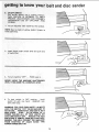
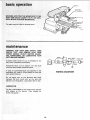
BEVEL SANDING
The worktable
can be tilted from 0 °
45 ° for
bevel sanding. Loosen the table lock knob and
tilt the worktable
to desired
angle as shown,
WARNING: TO AVOID TRAPPING
THE WORK
OR FINGERS BETWEEN THE TABLE AND SAND*
ING SURFACE, THE TABLE SHOULD BE REPOSITIONED ON THE TABLE SUPPORT ROD TO
RETAIN A MAXIMUM OF 1t16-|NCH
DISTANCE
BETWEEN DISC AND TABLE.
TABLE LOCK
KNOB
/
., TABLE
SUPPORT ROD
LOCKINGBOLTS
POSITIONING
BELT TABLE
Two belt table locking bolts lock
a vertical or horizontal position.
the belt table in
J
To adjust vertical position:
a. Remove the backstop,
b.
Loosen the two belt table Uocking bolts using
a 1/2-inch wrench+
c+ Position
belt table vertically
tighten the two bolts.
as shown
and
15
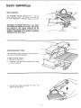
BELT
ABLESTOP
a:
Loosen theiocknut
using a:3/4-inch
wrench:
b. Place a levei on:the abrasive belt table and
using a 314-|nch wrench, screw the stop bolt
in or out until the belt table is level.
c.
:Tighten the lOck:nut.
BACKSTOP
WORKP_ECE
SURFACE SANDING
ON THE SANDING
BELT
Hold the workpiece firmly
with both hands,
keeping fingers away from the sanding belt.
Keep the end butted against the backstop
move the work evenly across the sanding
Use extra caution when sanding very thin
For sanding
and
belt.
long pieces, remove the backstop.
Applyonly enough pressure to allow the sanding
belt:to remove material.
SANDINGBELT
SANDING
BELT
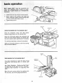
END SANDING
ON THE SANDING
BELT
TABLE
BELT
WORKTABLE
ASSE M BLY
it is more convenient
to sand the ends of long
workpieces
with sanding belt in a vertical position.
See "Basic Operation - Positioning
Belt Table"
for adjusting the belt table, and see "Assembly Installing Table Assembly"
for adjusting
worktable.
Move
the work evenly across the sanding
For accu racy, use a miter gauge (accessory).
_._.
.-_
belt.
i
/
WORKPIECE
16
,,
SANDING
CURVED EDGES
CURVED EDGES
Sand inside curves on the idler pulley.
Sand outside
....
_
SANDING
SANDING
:
curves on the sanding disc.
.i.,_,.
L J u
_
, ,I
I
I,
:
.4!
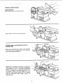
SMALL END SURFACES ON THE
DiSC
...::'..
Move the work across the center to the left side
of the face of the sanding disc. For accuracy,
use a miter gauge (accessory).
COMBINATIONSQUARE
NOTE: Use a combination
square to square the
miter gauge to the face of the disc (combination
square must be "true" -- See Start of Assembly
section on page 6 for checking method). If it is
not square, Joosen the miter gauge knob and
move the miter gauge slightly until it is square.
Without
moving the miter gauge, tighten
the
knob securely.
17
_:_:::iii:!ii!:::i=ii,!,ii:i:::i_i
:iiii:::i:
i ! iiii!:_i
¸!!:i:_::i
:::i:i::!i
:i::i::
:!::¸¸:¸::¸:¸¸
CENTER
WORKPIECE
LEFT OFCENTER)
BE HAZAR
The table may be titted' for beveled work,
i
maintenance
WARNING: I FOR YOUR OWN SAFETY, TURN
SWITCH :::"OFF,: AND REMOVE
PLUG FROM
POWER SOURCE:OUTLET
BEFORE ADJUST,
ING,: MAINTAINING,:: OR LUBRICATING
YOUR
BEL_T,AND DISC SANDER: ....
BLACK
if:power cord is worn or cut, or damaged
WRY;_have;itl replaced immed iately.
BLACK JUMPER
POWER CORD
in any
WHITE
s_
any dust
,_
A:-coat-of automobile-type
wax ::applied to::the
Wbrktai_ie will rhake it a: littie:easier
to: feed the
work:while: finishing,
: =
|
WiRiNG
-
Do'i::noi!apply wax to: the abrasive
belt table
because the belt could pick: up the wax and
deposit it on:the pulleys, causingthe
belt to stip.
LUBRICATION
The BALL BEARINGS in this machine are packed
with grease at the factory.
They require
no
further lubrication.
18
"_
WHITE
DIAGRAM
(/GREEN
-
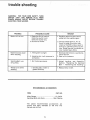
troubleshooting
WARNING:
FOR YOUR OWN SAFETY, TURN
SWITCH
"OFF"
AND REMOVE PLUG FROM
POWER SOURCE OUTLET BEFORE TROUBLE
SHOOTING YOUR SANDER.
TROUBLE
Motor will not run.
Machine slows down
when sanding.
PROBABLE CAUSE
REMEDY
"l,l'J,U_l'l'LllL
.........
1. Defective On-Off switch.
Defective switch cord.
Defective switch box.
2. Burned out motor.
Decrease belt tension,
nance Section.
2. Ease up on pressure.
,
2. Applying too much pressure to
workpiece.
1. Not tracking
Wood burns while
sanding,
I. Sanding disc or belt is
glazed with sap.
properly,
,,i
,i
i i
,ml ,i i
,,,,i
1. Replace disc or belt.
ACCESSORIES
ITEM
CAT. NO.
Miter Gauge ................................................ 9--24214
Sanding Belts and discs ....................... See Catalog
The above
recommended
current
and were available
manual was printed.
19
see Mainte-
1. Adjust
tracking,
see Assembly
Section,
"Replacing
the Sanding
Belt -- Tensioning
and Tracking"
,,,,:,,,,,
......................................
RECOMMENDED
i
1, Replace defective parts before
using belt disc sander again.
2, Consult Sears Service. Any attempt to repair this motor may
create a HAZARD unless repair is
done by a qualified service technician. Repair service is available at
your nearest Sears Store.
1. Timing'belt"'- too tight.
Sanding Belt runs
off pulleys,
JJ, J,,,,
accessories
at the time
are
this
n!'parts
lz:
i.ml
z
O3
_J
(/)
0
1:3
Z_ _,..
:::-
A
t_z
0
il
..%
ix:
_1_ ¸
Q.
0
,¢',1
i :
::':: ?i::!i:: :"
Li,,I
Z
tO
m
ra
7_
me!.
zw-
'<d
_z
_ ,,-I,'5
c
I,L
,,_ca $'
I_0
x
o_.B
m
"6
0
c
u.
1
o
€_
-r-
a.
-o
o
r
d
d_
0
z!
>_
<
21
ii ¸ z
,_
_H
•
_u
i • i¸k¸, •-
22
23
BEL 7"A ND DiSC
SANDER
SERVgCE
Now that you have purchased
your Belt & Disc
Sander should
a need ever exist for repair parts
or service,
simply
contact
any Sears Service
Center and most Sears, Roebuck
and Co. stores.
Be sure to provide
all pertinent
facts when you
call or visit.
The model number of your Belt and Disc Sander
will be found on a plate attached
to your sander
on the back side of the base.
MODEL NO.
113=226421
HOW TO ORDER
REPAIR PARTS
WHEN
ORDERING
REPAIR
PARTS,
GIVE THE FOLLOWING
INFORMATION:
ALWAYS
PART NUMBER
PART DESCRIPTION
MODEL NUMBER
113.226421
NAME OF ITEM
Belt And Disc Sander
All parts listed may be ordered
from any Sears
Service
Center
and most
Sears stores.
If the
parts you need are not stocked
locally,
your
order wilt be electronically
transmitted
to a Sears
Repair Parts Distribution
Center for handling.
Sold by SEARS,
Part No, SP49t6
ROEBUCK
AND
CO., Chicago,
Form No. SP4916
IL. 60684 U.S.A.