1
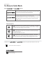
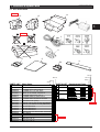
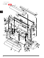
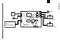
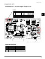
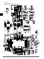
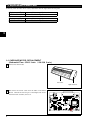
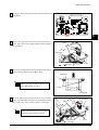
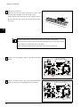
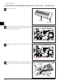
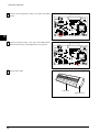
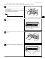
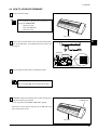
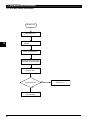
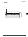
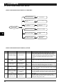
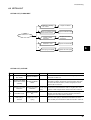
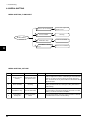
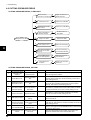
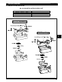
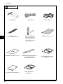
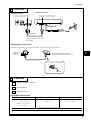
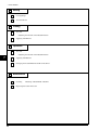
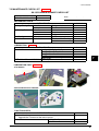
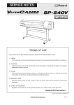
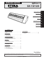
SERVICE NOTES
SX-15/12/8
Structure & Spare Parts
1
Electrical Section
2
Replacement of Main Parts
3
Adjustment
4
Supplemental Information
5
Troubleshooting
6
Service Activities
7
Contents
1 Structure & Spare Parts
1-1 ACCESSORIES ............................................................................ 1
1-2 BODY ........................................................................................... 2
2 Electrical Section
7 Service Activities
7-1 INSTALLATION CHECK LIST .................................................... 25
7-2 MAINTENANCE CHECK LIST .................................................... 29
7-3 Specification ............................................................................... 30
2-1 WIRING MAP ............................................................................... 4
2-2 MAIN BOARD ASSY ..................................................................... 5
2-3 PANEL BOARD ASSY .................................................................. 7
3 Replacement of Main Parts
3-1 CARRIAGE MOTOR_REPLACEMENT ........................................ 8
3-2 GRIT MOTOR_REPLACEMENT ................................................ 12
3-3 CUTTER PROTECTION_REPLACEMENT ................................ 15
4 Adjustment
4-1 Special Tools .............................................................................. 16
4-2 SERVICE MODE ........................................................................ 16
4-3 HOW TO UPGRADE FIRMWARE ............................................. 17
5 Supplemental Information
5-1 OPERATIONAL SEQUENCE ..................................................... 18
5-2 SENSOR MAP ............................................................................ 19
6 Troubleshooting
6-1
6-2
6-3
6-4
6-5
START & END POINTS DON’T MATCH ....................................
STITCH CUT ..............................................................................
MEDIA SHIFTING .......................................................................
TOOL UP/DOWN ERROR .........................................................
CUTTING PRESSURE ERROR .................................................
20
21
22
23
24
Third Edition
Windows and MS-DOS are registered trademark or trademark of Microsoft Corporation in the United States and/or other countries.
Unauthorized copying or transferral, in whole or in part, of this manual is prohibited.
SX-15/12/8 ‘04. Jul.
Copyright © 2003 ROLAND DG CORPORATION
5673-02
Revision Record
Revision
No.
Date
Description of Changes
0
2001.10.4
First Edition
Approval Issued by
Inagaki
Kaneko
Inagaki
Tamaki
Inagaki
Mabuchi
1-2 : BODY Each parts have been revised.
1
2003.5.2
7-1 : MAINTENANCE CHECK LIST hase been revised.
2
2004.7.23
1-1 : ACCESSORIES Each parts have been revised.
To Ensure Safe Work
To Ensure Safe Work
About
and
Notices.
Used for instructions intended to alert the operator to the risk of death
or severe injury should the unit be used improperly.
Used for instructions intended to alert the operator to the risk of injury
or material damage should the unit be used improperly.
* material damage refers to damage or other adverse effects caused
with respect to the home and all its furnishings, as well to domestic
animals or pets.
About the Symbols
symbol alerts the user to important instructions or warnings. The specific
The
meaning of the symbol is determined by the design contained within the triangle.
The symbol at left means Òdanger of electrocutionÓ.
The
symbol alerts the user to items that must never be carried out (are
forbidden). The specific thing that must not be done is indicated by the design
contained within the circle.
The symbol at left means not to touch.
The
symbol alerts the user to things that must be carried out. The specific
thing that must be done is indicated by the design contained within the circle. The
symbol at left means the power-cord plug must be unplugged from the outlet.
In addition to the
and
: Tips and advise before the adjustment.
Turn off the primary power SW
before servicing.
symbols, the symbols shown below are also used.
SX-15/12/8
1 Structure & Spare Parts
1 Structure & Spare Parts
1-1 ACCESSORIES
Revised2
14
13
12
1
1
S2
Revised2
S1
2
3
S3
6
7
8
5
11
4
9
S4
10
SX-15
SX-12
SX-15
SX-8
SX-12
SX-8
PARTS LIST -Main Parts1
2
3
4
5
6
7
8
9
10
11
12
13
14
Parts No.
22425111
23495214
13499109
13439801
23495125
13499111
23495124
13499209
26015343
26015344
21545147
21545146
21545145
22405214
21545155
21545154
22605122
22605123
22605124
Parts Name
POWER UNIT,AC-ADP.DCP-801
AC CORD VCTF 100V 7A 3P-S
AC CORD SJT 117V 10A 3PVC
CABLE-AC 3P CHINA 10A/250V S
AC-CORD H05VV 230V 10A S
AC CORD H05VV-F 240VE 10A S
AC CORD 3ASL/100 240VA 10A SAA
ADAPTER PLUG (100V)
MANUAL,USE JP SX-15/12/8 (JAPANESE)
MANUAL,USE EN SX-15/12/8 (ENGLISH)
PAD,CUTTER SX-8
PAD,CUTTER SX-12
PAD,CUTTER SX-15
DISK-CD,RSP-019 SOFTWARE PACKAGE
PAD,L SX-15
PAD,R SX-15
CARTON 2, SX-8
CARTON 2, SX-12
CARTON 2, SX-15
PARTS LIST -Supplemental PartsParts No.
*
*
*
*
*
*
*
*
*
*
*
*
*
*
*
*
*
*
*
*
*
*
*
*
*
*
*
*
*
*
*
S1
S2
S3
S4 12399354
Parts Name
PAD, R SX-8
G2237623
G2237622
PAD, R SX-15
G2237624
PAD, L SX-8
G2237621
PAD, L SX-15
CARTON,SX-8
G2627750
G2627751
CARTON,SX-12
G2607216
CARTON,SX-15
FILTER(E),LF-902 F540916
*
* *
*
* *
*
*
*
* * *
Revised2
*
*
* * *
* * *
* * *
*
*
*
Revised2
1
1 Structure & Spare Parts
1-2 BODY
Revised 1
23
9
12
S1
23
1
S15
S14
16
34
36
18
S15
27
S9
17
44
10
4
S3
29
7
54
30
S15
33
30
30
35
S13
31
30
53
32
49
42
18
S11
47
S20
S2
S5
24
46
S10
38
S9
5
S7
S4
25
29 27
51 S6
49
S9
37
48
S7
26
S11
2
29
S23(SX-12/8)
41
13
15
20
45
S16
S9
S10
S12
28
40(SX-15)
43(SX-12/8)
19
S11
1
S17
50
49 47
S7
S22
S14
5
S17
39
3
21
S10
S8
S19
S21
20
S18
S11
S20
S9
28
14
S11
52
2
1
11
6
43
24
8
22
S9
S9
1 Structure & Spare Parts
SX-15
SX-12
SX-8
PARTS LIST
1
2
3
4
5
6
7
8
9
10
11
12
13
14
15
16
17
18
19
20
21
22
23
24
25
26
27
28
29
30
31
32
33
34
35
36
Parts No.
11879124
22355759
22355760
21925123
21925124
21925125
12159532
22495501
7567307000
22815143
22815144
22815142
22025561
22025562
22025563
22025567
22025568
22025564
22025565
22025566
7567313600
21685139
21655215
7567309000
22475113
22145449
7567320010
7567413500
7567313500
21545147
21545146
21545145
7567320020
21535127
7567312000
22055494
22055309
21565104
11889107
11519109
21505112
22295246
22295240
22295241
22295242
22295250
22295249
22295245
22295247
22295251
22295252
22295248
7567508000
7567408000
7567308000
-Main PartsParts Name
ABSORBER,FF-7 SX-15
BASE,C-MOTOR SX-15
BASE,G-MOTOR SX-15
BELT,B248MXL4.8 SX-8
BELT,B347MXL4.8 SX-12
BELT,B427MXL4.8 SX-15
BUSH,80F-0204
BUTTON,SW SX-15
CARRIAGE ASSY SX-15
CHASSIS,SX-8
CHASSIS,SX-12
CHASSIS SX-15
COVER,FRONT SX-8
COVER,FRONT SX-12
COVER,FRONT SX-15
COVER,SIDE L SX-15
COVER,SIDE R SX-15
COVER,TOP SX-8
COVER,TOP SX-12
COVER,TOP SX-15
DRIVE PULLEY ASSY SX-15
GEAR,H51S6(B5C9) SX-15
HOLDER,SW SX-15
IDLE PULLEY ASSY SX-15
KNOB,SX-15
LEVER,P-ROLLER SX-15
MAIN BOARD ASS'Y SX-15
MOTOR ASSY SX-12
MOTOR ASSY SX-15
PAD,CUTTER SX-8
PAD,CUTTER SX-12
PAD,CUTTER SX-15
PANEL BOARD ASS'Y SX-15
PIN,F-COVER SX-15
PINCH ROLLER STAY ASSY SX-15
PLATE,C-MOTOR SX-15
PLATE,SOLENOID JOINT STX-7
P-ROLLER,FD14.6S8 SX-15
R-BEARING,D10S6(B3FL)
RING,CRESCENT 8
ROLLER,FD13.8 SX-15
SHAFT,DRIVE PULLEY SX-15
SHAFT,G-ROLLER SX-8
SHAFT,G-ROLLER SX-12
SHAFT,G-ROLLER SX-15
SHAFT,GUIDE SX-8
SHAFT,GUIDE SX-12
SHAFT,GUIDE SX-15
SHAFT,IDLE PULLEY SX-15
SHAFT,P-ROLLER SX-8
SHAFT,P-ROLLER SX-12
SHAFT,P-ROLLER SX-15
PINCH ROLLER ASSY SX-8
PINCH ROLLER ASSY SX-12
PINCH ROLLER ASSY SX-15
SX-15
PARTS LIST
* * *
* * *
* * *
*
*
*
* * *
* * *
* * *
*
*
*
*
*
*
* * *
* * *
*
*
*
* * *
* * *
* * *
* * *
* * *
* *
* * *
* *
*
*
*
*
* * *
* * *
* * *
* * *
* * *
* * *
* * *
* * *
* * *
* * *
*
*
*
*
*
*
* * *
*
*
*
*
*
*
37
38
39
40
41
42
43
44
45
46
47
48
49
50
51
52
53
54
Parts No.
22435330
22175249
22175254
22175228
22175274
22175262
22175227
22175256
22715293
22135330SZ
22135401
22135399
22135352
22325437
22325436
22325434
7567314000
21965138
21965139
21965134
21965135
21965136
21965133
7567506000
7567406000
7567306000
-Main PartsParts Name
SOLENOID,STC-05A SX-15
SPRING,GEAR-C SX-15
SPRING,GEAR-G SX-15
SPRING,L P-ROLLER SX-15
SPRING,PEN DOWN SX-15
SPRING,PEN UP SX-15
SPRING,R P-ROLLER SX-15
SPRING,TENSIONER SX-15
STAY,BACK-UP SX-15
STOPPER,G-ROLLER B STX-7
STOPPER,G-SHAFT SX-15
STOPPER,P-ROLLER SX-15
STOPPER,RING STX-7/8
SUPPORT,FRAME SX-8
SUPPORT,FRAME SX-12
SUPPORT,FRAME SX-15
SW ASSY SX-15
TABLE,FRONT SX-8
TABLE,FRONT SX-12
TABLE,FRONT SX-15
TABLE,REAR SX-8
TABLE,REAR SX-12
TABLE,REAR SX-15
Y-RAIL ASSY SX-8
Y-RAIL ASSY SX-12
Y-RAIL ASSY SX-15
SX-12
SX-8
* * *
* * *
* * *
*
* * *
* * *
* * *
* * *
*
* * *
* * *
*
* * *
*
*
*
* * *
*
*
*
*
*
*
*
*
*
1
PARTS LIST -Supplemental PartsParts Name
S1 LABEL,STIKA LOGO SX-15 #LA351
S2 NUT,HEXAGON M2 C TYPE2
S3
S4
S5
S6
S7
S8
S9
S10
S11
S12
S13
S14
S15
S16
S17
S18
S19
S20
S21
S22
S23
22535327
31109803
NUT,SQUARE M4 C
31109602
PIN,SPRING 1.6*10 SUS WAVE-TYP
31119901
RIVET,NYLON SR3-5.5 B
31159905
SCERW,BINDING HEAD M2X8 BC
31019110
SCREW,SET WP M3*3 C
31199701
SCERW,BINDING HEAD P-TIGHT M3X10 BC 31019708
SCREW,C-SEMS M3*6 UNI-C
31679901
SCREW,CUP M3X6 NI
31289102
SCREW,CUP M3X4 UNI-C
31289104
SCREW,HEXAGONAL CAP M2X4 C
31049165
SCREW,RESIN KNURL M4*8 WH
31179101
SCREW,BINDING P-TIGHT 4*10 BC
31019704
WASHER,POLYSLIDER 3*6*0.4 CUT
31249953
WASHER,SPRING M2
31249308
SADDLE,LOCKING WIRE CHJ-05
31409810
WIRE-CLAMP,WL3-32
11769121
WIRE-CLAMP,YJ-110
BUSH,ROLL 3X2.5
31029825
RETAINING-RING, ETW−4
31149703
SCERW,BINDING HEAD P-TIGHT M3X8 C
31019701
WASHER,PLAIN 3*8*0.5 C (Only for SX-12/8) 31249202
Revised 1
Revised 1
Revised 1
Revised 1
3
2
CPU
HD6432673
32MHz
MOTOR
Driver
MOTOR
Driver
ADDRESS BUS
DATA BUS
19V
CN1
Flash ROM
512Kbyte
AC ADAPTER DCP-801
22425111
INPUT : AC100-240V 1.0A
OUTPUT : DC+19V 2.1A
19V
IEEE1284
Control
LATCH
5V 3.3V
CN5 CN6 CN4
FET
SOLENOID
22435330
CARRIAGE
MOTOR
SX-15 : 14PM-M 22435424
SX-12/8 : PM42S-096 22435423
GRIT
MOTOR
Voltage
Regulator
CN7
CENTRO I/F
SX-15 : 14PM-M 22435424
SX-12/8 : PM42S-096 22435423
2 Electrical Section
CN2 CN10
PANEL PANEL CABLE
BOARD
LED/SW LIMIT CABLE
16MHz
2 Electrical Section
2-1 WIRING MAP
4
MAINBOARD
2 Electrical Section
2-2 MAIN BOARD ASS'Y
MAIN BOARD ASS'Y_Component Diagram / Component Side
DIP SW
NO.
Function
1 Model Selection
2 Model Selection
3
4
Firmware Write
-
ON
OFF
SX-15
1 : OFF 2 : OFF
SX-12
1 : ON 2 : OFF
SX-8
1 : OFF 2 : ON
ON
OFF
Always OFF
2
Indicates revision of the circut board.
Electric Maintenance Part
IC No.
IC4
IC5
IC6
IC7
Q2
Description
AME8805AEFT
L4962A
A3966SLB
A3966SLB
2SK2796S
Function
3.3V regulator
5V regulator
Grit Motor Driver
Carriage Motor Driver
Solenoid Driver
5
NON
CN3
VCC
VCC3
5
4
3
2
1
1
2
3
4
8
7
6
5
VCC3
8
7
6
5
RA2
1
2
3
4
1
2
3
4
1
2
3
4
VCC
HTJ-020-05A
CN1
B3B-PH-K-S
1
2
3
B2B-PH-K-S
CN2
1
2
2
1
3
2
RA8
1
LED
Power
Limit
R3
10K
1
YCN35-8L 1K
RA9
DA0
DA1
AN4
AN5
R2
C6
R13
74LVC14AD
IC11C
74LVC14AD
IC11D
CE0.1u
+19V
R11
R12
FL23
RHWT035080X2
109
110
111
112
113
114
115
116
117
118
119
120
121
122
123
124
125
126
127
128
129
130
131
132
133
134
135
136
137
138
139
140
141
142
143
144
CE0.1u
C4
/CS0
/CS1
/CS2
/CS3
/CS4
/CS5
VCC3
VCC3
C5 RHWT035080X2
CE0.1u
FL24
10K 10K
R1
VCC3
74LVC14AD
2
IC11B
74LVC14AD
5
7
4
8
3
9
2
10
IC11A
74LVC14AD
IC3A
EXBV8V102JV
8
7
6
5
CN10
10K
R4
FWE
8
7
6
5
RA1
DSR-04
8
7
6
5
AN0
AN1
AN2
AN3
1
6
nCENT_ACK
5
7
4
8
3
9
2
10
1
2
3
4
/CS3
/CSF
/INT1284
CENT_BUSY
EXBV8V103JV
SW1
1
6
RA7
RA3
EXBV8V103JV
VCC3
5
6
7
8
5
6
7
8
4
3
2
1
4
3
2
1
YCN35-8L 10K
1
VCC3
4
3
YCN35-8L 10K
1
2
3
4
1
2
3
4
8
7
6
5
8
7
6
5
6
10
2
9
3
8
4
7
5
220
100
100
R5
1K
C8
CE0.1u
P52/SCK2/IRQ2
P53/ADTRG/IRQ3
PH2/CS6/(IRQ6)
PH3/CS7/OE/(IRQ7)
PG4/BREQO
PG5/BACK
PG6/BREQ
VCC3
P40/AN0
P41/AN1
P42/AN2
P43/AN3
VREF
AVCC
P44/AN4
P45/AN5
P46/AN6/DA0
P47/AN7/DA1
P54/AN12/IRQ4
P55/AN13/IRQ5
P56/AN14/DA2/IRQ6
P57/AN15/DA3/IRQ7
AVSS
NC
P35/SCK1/(OE)
P34/SCK0
P33/RXD1
GND
P32/RXD0/IrRXD
P31/TXD1
P30/TXD0/IrTXD
P80/EDREQ2/(IRQ0)
P81/EDREQ3/(IRQ1)
P82/ETEND2/(IRQ2)
MD0
MD1
R16
0
16MHz
CE0.1u
C7
R15
220
VCC3
LED
+
2.2u/50V
C15
10
2
9
3
8
4
7
5
R18
22K
VCC3
1SS355
D12
4
M5821B 220u/35V
+ C1
CE1000p
D15
C31
R46
10K
74LVC14AD
CE1000p
IC3B
RA10
5
2
D2
DTA114EKA
Q1
IN
GND
GND
C45
+
OUT
GND
GND
1SS355
IC5
L4962A
VCC3
7
4
5
6
74LVC14AD
2.2u/50V
IC3C
RA11
YCN35-8L 1K
4.7K
15K
R48
C44 CE2200p
R49
LED
2
12
13
CE0.033u
C46
VCC
RA12
YCN35-8L 1K
OUT
C11
CE0.1u
72
71
70
69
68
67
66
65
64
63
62
61
60
59
58
57
56
55
54
53
52
51
50
49
48
47
46
45
44
43
42
41
40
39
38
37
L1
150uH
1SS355
3
VCC3
VCC3
9
D0
D2
D1
D3
D6
D4
D7
D5
8
7
6
5
8
7
6
5
8
1
2
3
4
VCC3
1
2
3
4
1
2
3
4
10
2
9
3
8
4
7
5
6
1
R7
10K
VCC
CE0.1u
C9
IC3F
74LVC14AD
CE0.1u
C10
220u/35V
RA15
R6
10K
R14
100
10K
VCC3
VCC3
D3
CE0.1u
2SK2796S
Q2
+19V
C13
VCC3
/CSF
/RD
/HWR
C47
CE0.1u
YCN35-8L 1K
SM5819A
VCC3
VCC3
RA16
VCC3
1
2
3
4
EXBV8V103JV
8
7
6
5
RA5
6
R19
10K
100
100
R58
R54
R59
/RESET
VCC3
1
YCN35-8L 1K
RA14
EXBV8V103JV
8
7
6
5
RA6
10
2
9
3
8
4
7
5
/RESET
100
R60
74LVC14AD
IC3D
C12
CE0.1u
+ C2
220u/35V
+ C3
VCC3
GEB
GEA
GPB
GPA
CEB
CEA
CPB
CPA
FWE
D4
D5
D6
D7
D0
D1
D2
D3
VCC3
CLKOUT
10
74LVC14AD
IC3E
AME8805AEFT
D1
GND
IN
M5821B
D16
1
IC4
VCC3
2
6
1
11
YCN35-8L 10K
RA13
/RST
PD7/D15
PE0/D0
PE1/D1
PE2/D2
PE3/D3
VCC3
PE4/D4
PE5/D5
PE6/D6
PE7/D7
FWE
P61/TMRI1/DREQ1/IRQ9
P60/TMRI0/DREQ0/IRQ8
P27/PO7/TIOCB5/EDRAK1/(IRQ15)
P26/PO6/TIOCA5/EDRAK0/(IRQ14)
P25/PO5/TIOCB4/(IRQ13)
P24/PO4/TIOCA4/(IRQ12)
P23/PO3/TIOCD3/(IRQ11)
P22/PO2/TIOCC3/(IRQ10)
P21/PO1/TIOCB3/(IRQ9)
P20/PO0/TIOCA3/(IRQ8)
P17/PO15/TIOCB2/TCLKD/EDRAK3
P16/PO14/TIOCA2/EDRAK2
P15/PO13/TIOCB1/TCLKC
P14/PO12/TIOCA1
GND
P13/PO11/TIOCD0/TCLKB
P12/PO10/TIOCC0/TCLKA
P11/PO9/TIOCB0
P10/PO8/TIOCA0
P75/EDACK1/(DACK1)
P74/EDACK0/(DACK0)
P73/ETEND1/(TEND1)
VCC3
NMI
WDTOVF
IC1
HD6432673-QFP144
YCN35-8L 1K
C30
3
10K
R53
VCC3
6
RA4
EXBV8V102JV
8
VCC3
/CENT
/CENT_STD
A0
A1
A2
A3
A4
A5
A2
A0
A3
A1
A4
A6
A5
A7
5
7
4
8
3
9
2
10
/HWR
/RD
6
1
3
9
CLKOUT
A6
A7
A8
A9
A10
A11
SS
15
6
C29
27p
OS
14
5
D8
D9
D10
D11
A18
A19
A20
A21
A22
A23
NON
C50
B2B-EH
1
2
CN4
/RD
/HWR
/RESET
D0
D1
D2
D3
D4
D5
D6
D7
D8
D9
D10
D11
D12
D13
D14
D15
27
46
26
28
11
12
29
31
33
35
38
40
42
44
30
32
34
36
39
41
43
45
D8
D9
D10
D11
D12
D13
D14
D15
A0
A1
A2
A3
A4
A5
A6
A7
A8
A9
A10
A11
A12
A13
A14
A15
A16
A17
VCC3
RY/BY
BYTE
nINIT
nSTROBE
nSELECT_IN
nAUTO_FEED
IC21
37
15
47
25
24
23
22
21
20
19
18
8
7
6
5
4
3
2
1
48
17
OC
CLK
1D
2D
3D
4D
5D
6D
7D
8D
VCC3
A1
A2
A3
A4
A5
A6
A7
A8
A9
A10
A11
A12
A13
A14
A15
A16
A17
A18
C49
CE0.1u
1
11
2
3
4
5
6
7
8
9
A1
B1
B2
B3
B4
B5
B6
B7
B8
IC9
33
32
31
30
29
28
27
26
25
24
23
VCC3
G
DIR
A1
A2
A3
A4
A5
A6
A7
A8
DA1
DA0
VCC5
G
DIR
6
5
2
3
-
+
-
+
19
1
13
BA10358F
7
IC19B
GPA
GPB
GEA
GEB
BA10358F
1
IC19A
CPA
CPB
CEA
CEB
VCC3
4
3
2
1
5
6
7
8
5
6
7
8
4
3
2
1
5
6
7
8
RA21
5
6
7
8
R31
1K
1.8K
R30
1K
C18
C16
CE0.1u
CE0.1u
VCC5D
EXBV8V330JV
EXBV8V330JV
RA23
5
4 5
6
3 6
7
2 7
8
1 8
EXBV8V103JV
R32
4
3
2
1
1.8K
5
6
7
8
EXBV8V330JV
RA22
5
4 5
6
3 6
7
2 7
8
1 8
RA20
4
3
2
1
5
6
7
8
33
EXBV8V330JV
RA17
5
4 5
6
3 6
7
2 7
8
1 8
4
3
2
1
RA18
R41
EXBV8V103JV
R33
4
3
2
1
4
3
2
1
CD4
CD5
CD6
CD7
4
3
2
1
4
3
2
1
CD0
CD1
CD2
CD3
IC11F
74LVC14AD
VCC3
12
VCC
19
1
2
3
4
5
6
7
8
9
CD0
CD1
CD2
CD3
CD4
CD5
CD6
CD7
2
3
4
5
6
7
8
9
SELECT_OUT
/RESET
TMS
nINIT
nSELECT_IN
nSTROBE
TDO
/CENT
/INT1284
CENT_BUSY
VCC
11
74VHCT245FT
74LVC14AD
A1
IC11E
20
CE0.1u 74VHCT245FT
IC20
18
B1
A1
17
B2
A2
16
B3
A3
15
B4
A4
14
B5
A5
13
B6
A6
12
B7
A7
11
B8
A8
10
VCC
18
17
16
15
14
13
12
11
C25
I/O
I/O
I/O
I/O
I/O
I/O
TDI
I/O
CLK0/I0
TDO
GND
GND
TCK
CLK1/I1
I/O
TMS
I/O
I/O
M4A3-32/32-10VC44
I/O
I/O
I/O
I/O
74LVC574
1Q
2Q
3Q
4Q
5Q
6Q
7Q
8Q
IC8
VCC3
1
2
3
4
5
6
7
8
9
10
11
/CENT_RD
STB_CLK
nCENT_ACK
CENT_BUSY
nPERROR
SELECT_OUT
nFAULT
19
18
17
16
15
14
13
12
D8
D9
D10
D11
A1
MX29LV400TTC-90
GND
GND
CE
OE
WE
RP
D0
D1
D2
D3
D4
D5
D6
D7
D8
D9
D10
D11
D12
D13
D14
D15
IC18
C20
CE0.1u
VCC3
TCK
/CS3
/RD
/HWR
TDI
C48
CE0.1u
VCC3
/CENT_RD
STB_CLK
nCENT_ACK
/CENT_STD
D12
D13
D14
D15
44
43
42
41
40
39
38
37
36
35
34
I/O
I/O
I/O
I/O
I/O
GND
VCC3
I/O
I/O
I/O
I/O
I/O
I/O
I/O
I/O
VCC3
GND
I/O
I/O
I/O
I/O
I/O
12
13
14
15
16
17
18
19
20
21
22
nFAULT
nAUTO_FEED
nPERROR
C34
27p
11
6
A10
A8
A11
A9
A12
A14
A13
A15
5
7
4
8
3
9
2
10
1
FC
1
A12
A13
A14
A15
A16
A17
FB
10
6
108
107
106
105
104
103
102
101
100
99
98
97
96
95
94
93
92
91
90
89
88
87
86
85
84
83
82
81
80
79
78
77
76
75
74
73
A18
A16
A19
A17
A20
A22
A21
A23
YCN35-8L 10K
/CENT
D8
D10
D9
D11
D14
D12
D15
D13
5
7
4
8
3
9
2
10
1
DATA4
DATA5
DATA6
DATA7
DATA0
DATA1
DATA2
DATA3
/STB
1
8
0.68 1/2W
R27
/GVREF
SENSE1
SENSE2
VREF
SENSE1
SENSE2
VREF
R51
1K
VBB
GND
GND
OUT1A
OUT1B
OUT2A
OUT2B
VBB
R35
GND
GND
R34
1K
R38
39K
CE1000p
C32
4
13
1
6
16
11
7
+19V
39K
CE1000p
C33
4
13
1
6
16
11
7
+19V
R52
3.9K
CB1608-601Y
OUT1A
OUT1B
OUT2A
OUT2B
R50
1K
PHASE1
PHASE2
ENABLE1
ENABLE2
VCC
IC6
A3966SLB
TCK
TMS
TDO
TDI
FL22
CB1608-601Y
FL20
CB1608-601Y
FL18
CB1608-601Y
FL16
CB1608-601Y
FL14
CB1608-601Y
FL12
PHASE1
PHASE2
ENABLE1
ENABLE2
VCC
IC7
A3966SLB
/SELECTIN
/FAULT
/INIT
/ACK
BUSY
PERROR
SELECT
/AUTOFD
R26 0.68 1/2W
5
12
8
2
15
3
14
10
VCC
C17
CE0.1u
YCN35-8L 10K
RA19
R29 0.68 1/2W
5
12
R28
0.68 1/2W
/CVREF
2
15
3
14
10
VCC
C19
CE0.1u
RA24
YC35L 3.3K
5
7
4
8
3
9
2
10
6
6
10
2
9
3
8
4
7
5
1
P51/RXD2/IRQ1
P50/TXD2/IRQ0
PH1/CS5
PH0/CS4
PG3/CS3
PG2/CS2
PG1/CS1
PG0/CS0
STBY
GND
XTAL
EXTAL
VCC3
PF7/CLKOUT
PLLVCC
RES
PLLVSS
PF6/AS
PF5/RD
PF4/HWR
PF3/LWR
PF2/LCAS/IRQ15
PF1/UCAS/IRQ14
PF0/WAIT
P65/TMO1/DACK1/IRQ13
P64/TMO0/DACK0/IRQ12
P63/TMCI1/TEND1/IRQ11
P62/TMCI0/TEND0/IRQ10
PD0/D8
PD1/D9
PD2/D10
PD3/D11
GND
PD4/D12
PD5/D13
PD6/D14
5
7
4
8
3
9
2
10
13
12
MD2
P83/ETEND3/(IRQ3)
P84/EDACK2/(IRQ4)
P85/EDACK3/(IRQ5)
VCC3
PC0/A0
PC1/A1
PC2/A2
PC3/A3
PC4/A4
PC5/A5
GND
PC6/A6
PC7/A7
PB0/A8
PB1/A9
PB2/A10
PB3/A11
GND
PB4/A12
PB5/A13
PB6/A14
PB7/A15
PA0/A16
PA1/A17
GND
PA2/A18
PA3/A19
PA4/A20
PA5/A21
PA6/A22
PA7/A23
NC
P70/EDREQ0/(DREQ0)
P71/EDREQ1/(DREQ1)
P72/ETEND0/(TEND0)
1
2
3
4
5
6
7
8
9
10
11
12
13
14
15
16
17
18
19
20
21
22
23
24
25
26
27
28
29
30
31
32
33
34
35
36
1
8
4
RC
9
RC
2
9
6
Y1
R56
10K
C23
CE0.1u
C24
CE0.1u
FL21
CB1608-601Y
FL19
CB1608-601Y
FL17
CB1608-601Y
FL15
CB1608-601Y
FL13
CB1608-601Y
R57
10K
VCC3
LCB2012-300Y
LCB2012-300Y
FL4
SM5819A
SM5819A
D4
D5
SM5819A
SM5819A
FL1 LCB2012-300Y
FL2 LCB2012-300Y
FL3
D6
D7
D8
SM5819A
SM5819A
FL5 LCB2012-300Y
FL6 LCB2012-300Y
D9
19
20
21
22
23
24
25
26
27
28
29
30
31
32
33
34
35
36
LCB2012-300Y
LCB2012-300Y
FL8
D10 SM5819A
D11 SM5819A
FL7
CN7
VCC
NON
1
2
3
4
5
6
7
8
CN11
41036S3NTBA
1
2
3
4
5
6
7
8
9
10
11
12
13
14
15
16
17
18
1SS355
D13
VCC3
B6B-EH
6
5
4
3
2
1
CN5
B6B-EH
6
5
4
3
2
1
CN6
2 Electrical Section
MAIN BOARD ASS'Y_Circuit Diagram
2 Electrical Section
2-3 PANEL BOARD ASS'Y
PANEL BOARD ASS'Y_Component Diagram / Component Side
2
PANEL BOARD ASS'Y_Circuit Diagram
D14
Power LED
L5T3LB5C-D1-AV
Power SW
CN9
1
2
3
SW2
TSTB-2
03DS-8E
PANEL BOARD
7
3 Replacement of Main Parts
3 Replacement of Main Parts
Following table describes the necessary adjustment after the replacement of each parts.
Replacement Parts
Necessary Adjustment
CARRIAGE MOTOR 1. Motor Backlash Adjustment
Replacement Parts
Necessary Adjustment
GRIT MOTOR
1. Motor Backlash Adjustment
3
3-1 CARRIAGE MOTOR_REPLACEMENT
(Referential Time : SX-15 3min. / SX-12/8 5 min.)
1
Remove the Front Table.
Front Table
Right Side Cover
2
Disconnect the Panel cable from the CN2 on the Main
Board. Unhook the bottom part of the Right Side Cover
from the Frame and then, remove it.
CN2
8
3 Replacement of Main Parts
3
Disconnect the Carriage Motor Cable from the CN6 on the
Main Board.
3
CN6
4
Remove the Spring and Screws for fixing the Carriage
Motor. Then, remove the C Motor Plate together with the
Spring
Carriage Motor.
C Motor Plate
Screws
Carriage Motor
5
Remove the Carriage Motor from the C Motor Plate and fix
the new Carriage Motor to the C Motor Plate.
C Motor Plate
Make sure that the fixing direction of
the C Motor Plate is correct.
Screws
Carriage Motor
6
Fix the C Motor Plate together with the new Carriage
Motor to the Motor Base temporarily and hook the Spring.
Then, tighten the screw in order as shown in the figure.
Motor Base
Spring
1
2
Make sure that there is no backlash
when the Carriage Motor is fixed.
Carriage Motor
Screws
9
3 Replacement of Main Parts
7
[SX-12/8 Load Check]
Make sure that the load when pulling the Carriage with
Tension Gauge (ST-001) is less than 6.6N (675gf).
(If the load is not the rated value, fix the Carriage motor to
the part where the gear engage the strongest and check the
PULL
load again.)
3
Backlash Adjustment is done automatically by the strength of the Spring.
However, it is necessary to check the load with the SX-12/8 because the motor torque
of the SX-12/8 is smaller than that of the SX-15.
When the load is bigger than the rated value, the loose-step could occur.
8
Connect the Carriage Motor Cable to the CN6 on the Main
Board.
CN6
9
Connect the Panel Cable to the CN2 on the Main Board.
Hook the bottom part of the Right Side Cover and fix it.
CN2
10
3 Replacement of Main Parts
10
Fix the Front Table.
Front Table
Right Side Cover
3
11
3 Replacement of Main Parts
3-2 GRIT MOTOR_REPLACEMENT (Referential Time : SX-15 3min. / SX-12/8 5 min.)
1
Remove the Front Table.
Front Table
Right Side Cover
3
2
Disconnect the Panel cable from the CN2 on the Main
Board. Unhook the bottom part of the Right Side Cover
from the Frame and then, remove it.
CN2
3
Disconnect the Grit Motor Cable form the CN5 on the Main
Board.
CN5
4
Remove the Spring and Screws for fixing the Grit Motor.
Then, remove the G Motor Base together with the Grit
Motor.
Spring
Screws
G Motor Base
Grit Motor
12
3 Replacement of Main Parts
5
Remove the Grit Motor from the G Motor Base and fix the
new Grit Motor to the G Motor Base.
G Motor Base
Screws
Make sure that the fixing direction of
the G Motor Base is correct.
3
Grit Motor
6
Fix the G Motor Base together with the new Grit Motor to
the Chassis temporarily and hook the Spring.
Then, tighten the screw in order as shown in the figure.
Spring
Chassis
Screws
1
Make sure that there is no backlash
when the Grit Motor is fixed.
2
G Motor Base
7
Grit Motor
[SX-12/8 Load Check]
Make sure that the load when pulling the Sheet with
Tension Gauge (ST-001) is less than 6.5N (660gf).
(If the load is not the rated value, fix the Grit Motor to the
part where the gear engage the strongest and check the load
again.)
PULL
Backlash Adjustment is done automatically by the strength of the Spring.
However, it is necessary to check the load with the SX-12/8 because the motor torque
of the SX-12/8 is smaller than that of the SX-15.
When the load is bigger than the rated value, the loose-step could occur.
13
3 Replacement of Main Parts
8
Connect the Carriage Motor Cable to the CN5 on the Main
Board.
3
CN5
9
Connect the Panel Cable to the CN2 on the Main Board.
Hook the bottom part of the Right Side Cover and fix it.
CN2
10 Fix the Front Table.
Front Table
Right Side Cover
14
3 Replacement of Main Parts
3-3 CUTTER PROTECTION_REPLACEMENT (Referential Time : 3min.)
1
Peel off the Cutter Protection from the machine and remove
it.
Using a commercially available cutter knife or the like may
make peeling easier.
As for the SX-15, raise the left and right sheet adjustment
levers and remove the Cutter Protection.
Use a cloth or the like to wipe away any remaining
adhesive on the machine.
3
2
Place the new Cutter Protection on the Front Table.
Use the reference line shown on the SX-15/12/8 as a guide
for alignment.
Reference Line
3
Peel off the double-sided tape and attach the new Cutter
Protection.
4
As for the SX-15, lower the left and right sheet adjustment
levers.
Sheet Adjust Levers
15
4 Adjustment
4 Adjustment
4-1 Special Tools
Table shows a list of special tools recommended by Roland DG Corp.
Tool No.
Tool Name
Purpose
ST-001
TENSION GAUGE 20N (2000g)
Measurement of the load in both
Carriage and Grit Roller direction.
4
4-2 SERVICE MODE
ROM VERSION CHECK DEMO
Connect AC Adapter to SX-15/12/8 while
pressing [STANDBY] key.
Release the [STANDBY] key and
make sure the Carriage moves to the origin.
Make sure the [STANDBY] LED is lit and
hold down the [STANDBY] key for
2 seconds or longer
STX-15/12/8 cuts the ROM Version.
For example SX-15
MAIN : A130
BOOT : B100
Turn off the power.
16
4 Adjustment
4-3 HOW TO UPGRADE FIRMWARE
1
Remove the Front Table.
It is necessary to prepare the followings to
upgrade the FIRMWARE.
1. Firmware Disk
2. PC with MS-DOS
3. Parallel Cable
Front Table
2
4
Connect the PC and the SX-15/12/8 with the Parallel Cable.
Turn on the DIP SW-3 on the Main Board and connect the
AC adapter.
Main Board
ON
DIP
1
3
DIPSW
3
2
4
Open the [download.bat] file in the Firmware Disk.
Some PCs can not use the BAT FILE. Please
refer to the ReadMe File in the Firmware Disk.
4
STANDBY LED starts blinking slowly when the upgrade is
completed without any problem.
In case of problem, STANDBY LED blinks quickly.
STANDBY LED
Disconnect the AC adapter and turn off the DIP SW-3 and
then, fix the Front Cover.
Front Table
17
5 Supplemental Information
5 Supplemental Information
5-1 OPERATIONAL SEQUENCE
POWER ON
LED Lights up.
Carriage moves to
the left.
5
Detect Limit Position.
Carriage moves to the right
side of the left Pinch Roller.
Receive data.
Command Error
OK
Finish Cutting.
18
NG
LED flashes.
5 Supplemental Information
5-2 SENSOR MAP
LIMIT SW
This sensor detects the limit of the Carriage Moving Direction.
5
19
6 Troubleshooting
6 Troubleshooting
6-1 START & END POINTS DON'T MATCH
START & END POINTS DON'T MATCH_FLOWCHART
Blade Offset doesn’t
match with SX Offset.
Blade Holder is set
loose.
Scratch in the Cutter
Protection.
Set the Offset.
Secure the Blade Holder.
Replace the Cutter
Protection.
Start & End Points
don’t match.
6
6
Blade tip is wearing out.
Replace the Blade.
Bearing inside Blade Holder
doesn’t rotate smoothly.
Replace the Blade
Holder.
Motor Gear is meshed
too tight or too loose.
Motor Backlash
Adjustment.
START & END POINTS DON'T MATCH_OUTLINE
No.
CHECKING POINT
ACTION
1
Blade Offset doesn't
match with SX Offset.
Set the Offset.
2
Blade Holder is set
loose.
Secure the Blade
Holder.
3
Scratch in the Cutter
Protection.
Replace the Cutter
Protection.
4
Blade tip is wearing
out.
Replace the Blade.
5
Bearing inside Blade
Holder doesn't rotate
smoothly.
Replace the Blade
Holder.
6
Motor Gear is meshed
too tight or too loose.
Motor Backlash
Adjustment
20
REFERENCE
OUTLINE
Blade used on the SX has offset and therefore, tip is shifted
from its center. When the offset setting done on SX doesn't
match with the blade offset, offset correction won't be done.
Therefore, the starting and ending points won't match because
the direction of the blade slightly shifts from the correct
direction.
When Blade Holder is set loose to Carriage, the blade tip
becomes very shaky when cutting and results in distorted
figure.
Sect.3[Cutter
Protection_Repla
cement]
Cutter Protection is where the blade lands for cutting. If there is
scratch in the Cutter Protection, blade can not rotate smoothly
and cause the starting and ending points to be shifted.
When blade tip wears out, offset will be changed. Therefore, as
same as 1, the starting and ending point won't match especially
when cutting circles.
There are bearings inside the Blade Holder. When the bearings
don't rotate smoothly, direction of the blade slightly shifts from
the correct direction and therefore, starting and ending points
don't match.
When Motor Gear is meshed too tight or too loose, Tool
Carriage and Grit Roller will be driven unstable and results in
starting and ending points to shift.
6 Troubleshooting
6-2 STITCH CUT
STITCH CUT_FLOWCHART
Blade tip is wearing
out / cracks.
Bearing inside Blade Holder
doesn’t rotate smoothly.
Replace the Blade.
Replace the Blade Holder.
Stitch Cut
Scratch in Cutter
Protection.
Replace the Cutter
Protection.
Guide Bar is bent.
Replace the Guide Bar.
Limit Spring is distorted.
Replace the Limit Spring.
6
5
STITCH CUT_OUTLINE
No.
CHECKING POINT
ACTION
REFERENCE
1
Blade tip is wearing
out / cracks.
Replace the Blade.
When blade wears out or cracks, it will be caught by the sheet
and results in stitch cut.
2
Bearing inside Blade
Holder doesn't rotate
smoothly.
Replace the Blade
Holder.
There are bearings inside the Blade Holder. When the bearings
don't rotate smoothly, direction of the blade slightly shifts from
the correct direction, therefore, it will be caught by the sheet
which results in stitch cut.
3
Scratch in the Cutter
Protection.
Replace the Cutter
Protection.
4
Guide Bar is bent.
Replace the Guide
Bar.
When the Guide Bar is bent, the movement in the carriage
direction and Tool down are not done correctly and blade is
caught by the sheet and results in stitch cut.
5
Limit Spring is
distorted.
Replace the Limit
Spring.
When the Limit Spring is distorted, the tool down can not be
done smoothly and the tool hit the table and results in stitch cut.
Sect.3[Cutter
Protection_Repla
cement]
OUTLINE
Cutter Protection is where the blade lands for cutting. If there is
scratch in the Cutter Protection, blade is caught by the sheet
because it sticks deeper into the sheet and results in stitch cut.
21
6 Troubleshooting
6-3 MEDIA SHIFTING
MEDIA SHIFTING_FLOWCHART
Sheet is not set correctly.
Set the sheet again and
explain to user.
Pieces of Media.
Cleaning
Grit Roller is dirty.
Clean the Grit Roller.
Media Shifting
Pinch Roller is wearing
out.
Replace the Pinch Roller.
6
MEDIA SHIFTING_OUTLINE
NO.
22
CHECK POINT
ACTION
REFERENCE
OUTLINE
The most effective measure against media shifting is to set the
media straight to the machine. Small tilting of the media when
setting it up could result in big shifting especially doing long
print. As for the SX-15/12, please make sure to lower the Sheet
adjustment lever.
1
Sheet is not set
correctly.
Set the sheet again
and explain to user.
2
Pieces of Media
Cleaning
When dust as pieces of media is stick to the feeding place,
making contact with the dust during the cutting and results in
media shifting.
3
Grit Roller is dirty.
Clean the Grit Roller.
When dust such as pieces of Media is stick to the Grit Roller,
power to hold the sheet will be weakened and results in media
shifting. Use brush to clean the Grit Roller.
4
Pinch Roller is
wearing out.
Replace the Pinch
Roller.
When the Pinch Rollers wear out, power to hold the media will
be weakened and results in media shifting.
6 Troubleshooting
6-4 TOOL UP DOWN ERROR
TOOL UP DOWN ERROR_FLOWCHART
Guide Bar is broken.
Pen Up Spring comes off.
Tool Up Down Error
Replace the Guide Bar.
Fix the Pen Up Spring.
The screw fixing
the Solenoid is loose.
Tighten the screw.
Cut-line/Bad contact
in the Solenoid Wire.
Replace / Connect
the Solenoid Wire.
Solenoid Driver IC
is broken.
Replace the Solenoid
Driver Q2.
6
TOOL UP DOWN ERROR_OUTLINE
NO.
CHECK POINT
ACTION
REFERENCE
OUTLINE
Guide Bar is the place where the carriage moves. When the
Guide Bar is broken, the tool up/down can not be done
smoothly.
1
Guide Bar is broken.
Replace the Guide
Bar.
2
Pen Up Spring comes
off.
Fix the Pen Up
Spring.
3
The screw fixing the
Solenoid is loose.
Tighten the screw.
4
Cut-line /Bad contact Replace / Connect the
in the Solenoid Wire.
Solenoid Wire.
When there is cut-line and bad contact in the Solenoid Wire, the
current is not supplied from the Main Board to the Solenoid and
the carriage doesn't move.
5
Solenoid Driver IC is
broken.
When the Solenoid Driver Q2 is broken, the current is not
supplied to solenoid and result in tool up/down error.
Replace the Solenoid
Driver Q2.
When the Pen Up Spring comes off, the movement from the
Solenoid Driver doesn't supply and results in tool up/down error.
When the screw fixing the Solenoid is loose, the tool up/down
can not done smoothly because of the backlash.
23
6 Troubleshooting
6-5 CUTTING PRESSURE ERROR
CUTTING PRESSURE ERROR_FLOWCHART
Cutting Pressure Error
Amount of blade
extension is not adjusted.
Adjust the amount of
blade extension.
Guide Bar is bent.
Replace the Guide Bar.
Parallel pin for Guide
Bar is loose.
Replace the Guide Bar.
Front & Rear Table is
not fixed correctly.
Re-fix the Front &
Rear Table.
Warp in the Table.
Replace the Table.
Limit Spring is loose.
Replace the Limit Spring.
Limit Spring and Solenoid
Joint Plate are not fixed
correctly.
Re-fix the Limit Spring
and Solenoid Joint Plate.
Cut-line/Bad contact
in the Solenoid Wire.
Replace/Connect the
Solenoid Wire.
Solenoid Driver IC
is broken.
Replace the Solenoid
Driver Q2.
6
6
7
8
9
CUTTING PRESSURE ERROR_OUTLINE
NO.
1
24
CHECK POINT
The amount of blade
extension is not
adjusted.
ACTION
Adjust the amount of
blade extension.
REFERENCE
OUTLINE
When the amount of blade extension is not adjusted, cutting
pressure might not be correct.
2
Guide Bar is bent.
Replace the Guide
Bar.
When the Guide Bar is bent, the tool up/down is not done
smoothly and the blade does not land correctly, and results in
weak cutting pressure.
3
Parallel pin for the
Guide Bar is loose.
Replace the Guide
Bar.
When the parallel pin for the Guide Bar is loose, tool up/down
can not be done smoothly and the blade can not be landed
correctly, and results in weak cutting pressure.
4
Front & Rear Table is
not fixed correctly.
Re-fix the Front &
Rear Table.
When there is a backlash in the Front & Rear Table, the blade
is not landed correctly and results in weak cutting pressure.
5
Warp in the Table
Replace the Table.
When there is a warp in the Table, the blade is not landed
correctly and results in weak cutting pressure.
6
Limit Spring is loose.
Replace the Limit
Spring.
When the Limit Spring is loose, tool up/down can not be done
and SX can not cut.
7
Limit Spring and the Re-fix the Limit Spring
Solenoid Joint Plate and the Solenoid Joint
Plate.
are not fixed correctly.
8
Cut-line /Bad contact Replace / Connect the
in the Solenoid Wire.
Solenoid Wire.
9
Solenoid Driver IC is
broken.
Replace the Solenoid
Driver Q2.
When the Limit Spring and the Solenoid Joint Plate are not
fixed correctly, tool up/down is not done smoothly and results in
weak cutting pressure.
When there is cut-line and bad contact in the Solenoid Wire, the
current is not supplied from the Main Board to the Solenoid and
the carriage doesn't move.
When the Solenoid Driver Q2 is broken, the current is not
supplied to solenoid and result in tool up/down error.
7 Service Activities
7 Service Activities
7-1 INSTALLATION CHECK LIST
SX-15/12/8 INSTALLATION CHECK LIST
Model
SX-15 / SX-12 / SX-8
Serial Number
User
Date
SX-15/12 Repacking
SX-8 Repacking
7
25
7 Service Activities
Accessories
AC adapter x 1
Cable ties x 2
7
* For securing ferrite cores.
Power cord x 1
Blade holder/Blade x 1
Ferrite cores x 2
Material for test cuts x 1
*This blade holder and
bladeare installed on
the unit when shipped
from the factory.
Application tape for test cuts x 1
Replacement blade protector x 1
*The configuration differs
according to the model.
SX-15/12/8 User's Manual x 1
26
Roland CutChoicce
CD-ROM x 1
Roland Software Package
CD-ROM x 1
7 Service Activities
Connection
Parallel connector
Parallel connector
Use the screws on either side to
secure the connector in place.
Use the clips on either side to
secure the connector in place.
AC
ACAdapter
adapter jack
jack
Parallel Cable
The cable is available separately.
Be sure to use the correct cable for
the computer.
Attaching the ferrite cores
Attach the included ferrite core at the location on the connection cable shown in the figure.
20 to 30 mm
(13/16 to
1-3/16 in.)
7
20 to 30 mm (13/16 to 1-3/16 in.)
from the connector on the SX-15/12/8
*Secure in place with cable ties.
Cable tie
Preparation
Installing the Driver / Software
Installing Blade
Load the Material
Acceptable material size
SX-15
Width : 360 to 381 mm
(14-1/8 to 15 in.)
SX-12
Width : 280 to 305 mm
(11 to 12 in.)
SX-8
Width : 200 to 215 mm
(7-13/16 to 8-7/16 in.)
Width : 280 to 305 mm
(11 to 12 in.)
Length : 1100 mm (43-1/4 in.) or less
27
7 Service Activities
Setting
Cutting Range
Tool Conditions
Cutting
Test Cut
- Adjusting the Amount of the Blade Extension
Applying Cut Material
Operation
Test Cut
- Adjusting the Amount of the Blade Extension
7
Applying Cut Material
Changing the Loaded Material Width on the SX-15
Maintenance
Cleaning
Blade Tip / Blade Holder / Machine
Replacing the Cutter Protection
28
7 Service Activities
7-2 MAINTENANCE CHECK LIST
Revised 1
SX-15/12/8 MAINTENANCE CHECK LIST
SX-15
Model
SX-12
Serial No.
Date :
SX-8
.
.
.
MECHANICAL PARTS
CHECK POINTS
Carriage Driving Part Drive Gear
Backlash
Grit Driving Part
Drive Gear
Backlash
Grit Roller
Tool Carriage
Solenoid
Blade Holder
Blade Holder
LUBRICATION
CONFIRMATION
Foreign substance
Check Load
Backlash
Check Load
Foreign substance
Up/Down movement
Rotation of the Bearing
Scratch
Revised 1
CHECK POINTS
Floil G902Y
Carriage Idle Pulley Shaft
Carriage Drive Pulley Shaft
Carriage Drive Gear
Grit Drive Gear
Shaft Guide
GE Toshiba Silicones YG6260 Parallel pin of the Guide Bar
CONFIRMATION
7
LUBRICATION PART Revised 1
<Floil G902Y>
<GE Toshiba Silicones YG6260>
FUNCTION CHECK
CHECK POINTS
CONFIRMATION
Firmware Version
Upgrade the Firmware to the latest version.
Demo Cut
Cutting Quality
Noise
29
7 Service Activities
7-3 Specification
Max. cutting area
Acceptable sheet size
SX-15
SX-12
SX-8
340 mm (X) x 1000 mm (Y)
250 mm (X) x 1000 mm (Y)
160 mm (X) x 1000 mm (Y)
(13-3/8 in. (X) x 39-5/16 in. (Y) )
(9-13/16 in. (X) x 39-5/16 in. (Y) )
(6-1/4 in. (X) x 39-5/16 in. (Y) )
Width : 360 to 381 mm
Width : 280 to 305 mm
Width : 200 to 215 mm
(14-1/8 to 15 in.)
(11 to 12 in.)
(7-13/16 to 8-7/16 in.)
Width : 280 to 305 mm
(11 to 12 in.)
Length : 1100 mm (43-1/4 in.) or less
Length : 1100 mm (43-1/4 in.) or less
12 to 100 mm/sec.
12 to 40 mm/sec.
12 to 40 mm/sec.
(7/16 to 3-7/8 in./sec)
(7/16 to 1-9/16 in./sec)
(7/16 to 1-9/16 in./sec)
Cutting speed
Acceptable material
Length : 1100 mm (43-1/4 in.) or less
PVC sheet (0.1 mm (0.00394 in.) or less in thickness, 0.3 mm (0.0118 in.) or less in thickness
including
the backing board).
STANDBY key
Control keys
STANDBY LED
LED
Parallel (IEEE 1284 compliant: Nibble mode)
Interface
Exclusive AC adapter DC+19V 2.1A
Power consumption
External dimensions
7
510 mm (W) x 165 mm (D) x
430 mm (W) x 165 mm (D) x
105 mm (H)
105 mm (H)
105mm (H)
(20-1/8 in. (W) x 6-1/2 in. (D) x
(16-15/16 in. (W) x 6-1/2 in. (D) x
(13 in. (W) x 6-1/2 in. (D) x
4-3/16 in. (H) )
4-3/16 in. (H) )
4-3/16 in. (H) )
3.1 Kg (6.8 lb)
2.6 Kg (5.7 lb)
2.1 Kg (4.6 lb)
Weight (unit only)
60 dB (A) or less (According to ISO 7779)
Acoustic noise level
5 to 40 C (41 to 104 F)
Operation temperature
35 to 80 % (no condensation)
Operation humidity
Accessories
330 mm (W) x 165 mm (D) x
AC adapter : 1, Power cord : 1, Ferrite cores : 2, Cable ties (For securing ferrite cores) :2, Blade holder/Blade : 1, Material
for test cuts : 1, Application tape for test cuts : 1, Blade protect : 1, Roland Software Package CD-ROM: 1,
Roland CutChoice CD-ROM : 1, SX-15/12/8 User's Manual : 1
Interface Specification
[ Parallel ]
Standard
IEEE 1284 compliant: Nibble mode
Input signal
STROBE (1BIT), DATA (8BIT), SLCT IN, AUTO FEED, INT
Output signal
BUSY (1BIT), ACK (1BIT), FAULT, SLCT, PERROR
I/O signal level
TTL level
Transmission method
Asynchronous
30
SX-15/12/8