1
TECHNICAL & SERVICE MANUAL
-
-
\
Wireless type
Models
'
MS-OSDW-U1 c s w , w ~ ~- MSH-OSD W-U%SW,WGI
MSH-12DN-U1 ts&,woi
MSH-15DN-U1 CSWI
I
FEATURES
LCD wireless
remote controller
Models
MS-O9DW
MSH-O9DW
MSH-12DN
MSH-15DN
Cooling Capacity
9,000 BTU/h
8,800 BTU/h
12,500 BTU/h
14,500 BTU/h
Heating Capacity
-
10,900 BTU/h
12.500 BTU/h
15,000 8TU/h
SEER
10.59
9.9
9.7
9.1
COP
-
3.04
2.90
2.85
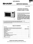
1. NEW "I F E U CONTROL" IN OUR LCD WIRELESS REMOTE CONTROLLER
Mitsubishi Electric's new wireless remote controller incorporates a number of advanced features that provide even greater
control and ease-of-use. It has a liquid crystal display which indicates such information as mode, fan speed and temperature
selected as well as the timer setting and time remaining. It is also equipped with "I Feel Control", a unique Miibishi Electric
feature that allows the user to adjust the temperature to exactly the level he or she wants simply by tapping the button that
describes present conditions : -To Cool" "Too Warm", or "Okay". The optimum temperature set this way is then memorized
for immediate recall whenever the air conditioner is used again. And what's more, the new controller has been made more
compact and easy to handle than even before.
2. A VARIETY OF MICROPROCESSOR-CONTROLLED FUNCTION
Auto Stop Mode
Automatic ON/OFF Timer
Convenient timer function includes Auto Start, Auto Stop, both can be
set 1-12 hours.
Auto Stop (Night Setback) Mode.
This mode raises (or lowers, when heating) the temperature setting by
1'F after one hour, and by another 1°F every half hour thereafter.
When two hours have passed, the air conditioner is running at a setting
that is 2°F higher, thus preventing excessive cooling.
Maximum temperature difference is 4°F for heating.
~ u t o m a t i cFan
' Speed Control
When there's a large difference between the set temperature and
existing room temperature, the fan speed automatically adjusts to HI to
either cool or heat the room quickly.
As the temperature differential decreases, the Fan Control shifts down
automatically to MED and LO. Operation is almost whisper quiet.
L
.
'
Stan
1
-
I
S
.
2
I Automatic Fan Soeed Control
8(YF
,
,
Wurt
---------------------------
kRmrn-
.--
7WF ------
Hot Start System
Heating always begins comfortably with warm air, since the Hot Start System prevents cold air from being blown out at the
start of heating and during defrosting. (All heat pumps.)
Booster Heater for Fast Warm-up.
Microprocessor controlled-Booster Heater automatically hastens the heating process to quickly warm up a room, and thereby
eliminates unnecessary energy use that occurs during prologned heating. (All heat pumps.)
Automatic Change Vane System
The Automatic Change Vane System will automatically set the vane in a horizontal positiolifor cooling. During heating
when the hot air is blowing strongly enough, it will automatically adjust downward. The angle of the vane can be
adjusted with the Remote Controller. (MSH-12/15DN)
Adjustable Change Vane System
Choose the air direction that suits your needs. To achieve uniform
aimow for heating, adjust the louver downward. For cooling, keep it
in a horizontal position. (MS(H)-O9DW)
During heatiyl
Restart Function (Optional)
The restart function restarts the equipment when power is restored
following an outage, selecting as required either cooling or heating
operation at a fixed temperature setting of 75F. (MS-OgDW, MSH09DW, MSH-12/15DN)
High Performance Rotary Compressor
The advanced design of Mitsubishi Electric's powerful and energyefficient rotary compressor results in lower operating costs and a longer
service life.
1
During cooling+
C
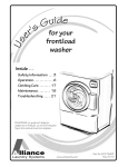
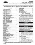
3 . EASY OPERATION BY LCD WIRELESS REMOTE CONTROLLER
Once the controls are set, the same operation mode can be repeated by simply turning the POWER SW on.
When batteries are replaced all of the controls memories should be canceled and "I FEEL CONTROL" mode is automatically
selected.
I
7
1
k
Sends sianal to control the air conditioner.
the signal is send t o indoor unit.
F
lndicates the selected
1 lndicates
FAN mode is only for straight COOLING
TYPE (MS-O9DW)
p
the selected
I FAN speed
@Button raises the temperature
@Button lowers the temperature
lndicatesthe timer mode
1
I 1
'00 COO!
, OKAY , TOO WARY 1
II
1 A selector for automatic ON/OFF of the air I
conditioner.
NORMAL : Continuos operation regardless of the timer setting
AUTO STOP : 12hr Automatic OFF Timer
AUTO START : 12hr Automatic ON Timer
time and displays the
remaining time in timer
E e this Button to set the time for timer
control operation.
@ : Increase by one hour each
@ : Decrease by one hour each
time the Button is pressed
I
-
operation of the unit, the desired temperature can be changed by pressing the folThe desired temperature will
from
the current room temperature.
COOL increase by about 2'F-4°F
O K n ~ The present temperature will be
IA
Button t o change the AUTO VANE
direction.
I
II
I
Switch to the air conditioner power ON/
Turns ON when pressed once and tums
I
memorized by microprocessor.
The desired temperature will
from
the current room temperature.
WARM decrease by about 2'F-4°F
*This instruction uses MSH-12DN LCD
wireless remote controller.
3
SPECIFICATIONS
i
-
'L
MODEL
-
ITEM
'
Capacities
-
1 47' *'
-COP
-INDOOR UNIT
- External finish
Power supply
- Max.
- fuse size (time delay)
- Min. ampacity
Fan motor
-Auxiliary
heater
-
W
W
8,800
1
10,900 (14,300)
55
Airflow Lo-Me-Hi
(17')
F.L.A.
A(kW)
CFM
CFM
in. I
in. I
in.
in.
Ibs.
V,Phase,Hz
A
- power supply
- Max. fuse size (time delay)
- Min. ampacity
F.L.A.
Model
Winding resistance (at 68°F)
R.L.A.
L.R.A.
Compressor
-
--Refrigerant control
- Defrost method
Dimensions
,
- Weight
0.5
I
-
0.4
lbs.
in.
ft.
h.
Heating
-
29
MUH-OSDW-U1
Munseil 5Y 6.5/1
115,1,60
I
15.0
13.5
20.0
16.0
0.8
KH419WAD
C-R 0.95 C-S 5.18
10
37
RHS135WAE
C-R 0.79 C-S 4.1 5
12
42
Capillary tube
I
Reverse cyde
29-15/16
9-1/16
71-1/4
-.
., .
I
73
W~relesstype
12V DC
Not supplied (optional parts)
1/4
3/8
-.
.
Flared
Flared
Max. 16
Max.33
Operating Range
Coding
I
I
26
MU49DW-U1
(heating) - lndoor : 7WFDB. 60'FWB. Outdoor : 47'FDB. 43'FWB
*2.Rating cond'ions (heating) - lndoor : 7WFDB, W W B , Outdoor : ITFDB, 15'FWB
*3.Hming capacity and power consumption in ( ) include auxiliary electric heater operation at 115V.
lndoor air intake temperature
90FDB, 71'FWB
67'FDB, 57'FWB
EKYFDB, 67.AWB
7WFDB. 6WFWB
8.7(1 .O)
5/8
33-1/2
5-1/8
15
* 1.Rating condiins (cooling) - lndoor : 8WFDB. 67'FWB. Outdoor : 95'FDB, 75'FWB
Maximum
Minimum
Maximum
Minimum
12.0
170-220-265
1!50-190-235
in
a,,.
U
I ,
I
3.04 (1.811 MSH-OSDW-U1
170-220-265
150-190-235
in.
in.
REMOTE CONTROLLER
Contml voltage (by built in transformer)
REFRIGERANT PIPING
' Liquid
Pipe size
Gas
Indoors
Connection method
Outdoom
Between the indoor Height difference
Piping length
& outdoor units
Notes
1
Woodgrain or silky White
115,1,60
15.0
W
D
,.--.
9.8 f9.91
V, Phase, Hz
A
D
H
- Fan motor
Yur
MS-OSDW-U1
- Cond. drain conn. ODI W
- Weight
UNIT
- OUTDOOR
- External finish
I
-
*2
Dry
I wn
Dimensions
10.5
- f10.591
.
.v--,.,
--a.
h
-
MSH-OSDW-U1
I
-
-F F R * ~I4FFRl
-
II
9,000
p
p
Power
consumption
-
BTU/h I
BTU/h 1
Cooling * l
Heating 47' *
Heating 17' *
Cooling*
Heating 47
Heating 17' * 2
MS-OSDW-U1
Outdoor air intake temperature
115'FDB
67'FDB
75FDB. 6FFWB
17'FDB. 1GFWB
79
i
-
-
-
MODEL
ITEM
Cooling
*'
'
Heating 47"*
Heating 1 7 " * ~
Cooling*
Heating 47" *
Heating 17"*2
Capacity
'
-
Power
consumption
'
EER*' (SEER)
COP
47"' 117")
INDOOR UNlT
External finlsh
Power supply
Max. fuse size (time delay)
Min. ampacity
Fan motor
Auxiliav heater
1
1
Airtlow Lo-Me-Hi
*2
Dv
Wet
Cond. drain conn. OD
Dimensions
' 1
BTU/h
BTU/h
BTU/h
W
W
W
W
D
H
MSH-12DN-U1
11,8OO/12,5OO
14,000/14,500
12,000/12,500~17,100/177600)*3
14,400/15,000(19.500/20.100)*3
6,240/6,500(11,340/11 .600)*3
8,600/9.m(1 3.700/14,100)*~
1,270/1,300
1,550/1.600
1,220/1,260(2,720/2,760)
1,480/1,540(2.980/3,040)*3
1,020/1,060(2,520/2,560)
1,280/1 .340(2.780/2.840)*~
9.0/9.0 (9.1/9.11
9.3/9.6 [9.5/9.7)
2.85/2.85 (2.0/2.01
2.9/2.9 [1.8/1.81
MSH-I2DN-U1
MSH-15DN-U1
Woodgrain or silky White
115,1,60
20.0
I
16.8
17.0
I
V, Phase,Hz
A
F.L.A.
A(kW)
CFM
CFM
in.
in.
in.
in.
Ibs.
Weight
OUTDOOR UNIT
Extemal finish
Power supply
V.Phase, Hz
A
Max. fuse size (time delay)
Min. ampacity
FLA
Fan motor
Model
Windtng reststance (at 68°F) il
Compressor
R.L.A
L RA
Refrigerant control
Defrost method
W
tn
in
D
D~mensions
H
in
Ibs.
Weight
REMOTE CONTROLLER
Control voltage (by built in transformer)
REFRIGERANT PIPING
Liquid
in. I
Pi~e
size
I
I ..
Connection method
Between the indoor
& outdoor units
Notes
MSH-15DN-U1
I
0.5
I
310-380-470
270-330-420
I
37
MUH-12DN-Ul
I
15.0
12.0
Cooling
Heating
-
-
04
RH-231NAB
C-R 1.73 C-S 3.25
10.0
34.0
Capfllary tube
Reverse cycle
33-1/2
11-7/16
23-7/8
104
Wtreless type
12V DC
Not supplied (optional parts)
..
1/4
.
1-
Flared
Flared
Max. 16
Max.49
h.
h.
lndoor air intake temperature
SWFDB, 71'WB
67"FDB. 57'FWB
WFDB, 67'AWB
7VFDB, 6OFWB
20.0
13.0
RH- I89NAB
C-R 2.07 C-S 3 . M
8:8
30.0
Operating Range
Maximum
Minimum
Muxirnum
Minimum
37.5
MUH-15DN-U1
Munsell 5Y 6.5/1
208/230,1,60
* 1.Rating conditions (cooling) - Indoor : 8CTFDB, 67'FWB. Outdoor : 95'FDB. 7 5 ' M B
(heating) - lndoor : 7CTFDB. GOFWB, Outdoor : 47'FDB, 43'WB
* 2.Rating conditions (heating) - lndoor : 7CTFDB, 6CTFWB. Outdoor : 1TFDB, 1 5 ' M B
* 3.lndudes auxiliaw electric heater operations 115V.
.
280-340-400
250-300-360
5/8
39-3/8
7
14-3/16
Indoors
Height difference
Piping length
0.4
13.0 (1.5)
Outdoor air intake temperature
11S'FDB
67'FDB
75'FDB. 6 5 ' W B
17'FDB. IVFWB
I
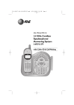
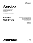
DATA
1. PERFORMANCE CURVE
Cooling capacity
SHF at rating condition = 0.71
Airflow = 265 CFM
Bypass Factor = 0.1 15
Outdoof D.B entering temp.rF)
Cooling capacity
Heating capacity
SHF at rating condition = 0.68
Airflow = 265 CFM
Bypass Factor = 0.1 1
Airflow = 250 CFM
70
70
15
Outdoor D.B entering temp.
6
25
35
45
55
Outdoor W.B entering temp.
('F)
Heating capacity
Airflow = 470
Outdoor D.8 entering temp.rF)
Outdoor W.B entering temp.
('F)
Heating capacity
Ai*
= 400
Outdoor D.6 entering temp. ('F)
Outdoor W.B entering temp. ('F)
2. OPERATING RANGE
(1) POWER SUPPLY
I
I
Indoor unit
Outdoor unit
I
Models
(
MSH-O9DW
MSH-12DN
Rating
Guaranteed voltage
I
115V 1 phase 60Hz
Min. 103V- Max. 127V
t
MU-O9DW
MUH-O9DW
MUH-12DN
MUH-15DN
Min. 198V - Max. 253V
(2) OPERATION
Function
1
Indoor
Entering air temp.
Condition
Standard temp.
Outdoor
DB ('F)
WB ('F)
DB ("F)
67
80
WB ('F)
-
95
Maximum temp.
95
71
115
-
Minimum temp.
67
57
67
-
I
i
I
Cooling
Maximum humidi
I
Heating
-
78%
I
I
43
60
47
70
60
17
15
80
-
75
65
High temp.
70
Low temp.
(Minimum temp.)
Maximum temp.
1
La
3. OUTLET AIR SPEED AND COVERAGE RANGE
I
Model
Function
/
Airflow
ICFM)
/
(8)
DV
400
15
26
Wet
360
14
24
MSH-15DN- (U1I
.The air coverage range is the value up to the position
where the air speed is 1 ft/sec. when air is blown out
horizontally from the unit properly at the High speed
position.
The coverage range should be used only as a general
guideline since it varies according to the size of the
room and furniture installed inside the room.
Air speed Covera e
(ft/sec) /range
m
4. ADDITIONAL REFRIGERANT CHARGE (R-22
I
I
Model
Outdoor unit
precharged
(up t o 25 ft)
(02))
1
I
Refrigerant piping length (one way)
25 f t
3 0 ft
33 ft
2 Ibs 12 oz
0
1
1
MSH-O9DW- lUll
3 Ibs
0
3
5
Model
Outdoor unit
precharged
(up to 25 ft)
I
-
MS-O9DW-
a
MSH-12DN- jU1J
3 Ibs 1 2 0 ~
MSH-1SDN-
3 Ibs 8 oz
I
Refrigerant piping length (one way)
25 ft
3 0 ft
3 5 ft
4 0 ft
4 5 ft
49 f t
0
3
5
8
11
13
5. MAX. REFRIGERANT PIPING LENGTH & MAX. HEIGHT DIFFERENCE
I
Model
length (ft)
Height
difference (ft)
(A)
Additional piping
Max. length
A
* It does .not matter whether the indoor unit or outdoor unit
is higher.
9
M~del
MS-WDW-U1
('h=N
M n g
Cooling
Heating
BTU/h
9.000
8.800
10,900(14,300)
-
0.71
0.68
SHF
Total
I
I kw I
I Input
0.86
amit
I
input
-
kw
I
0.04
0.04
I
0.04(1.04)
0.4
Am. heater wnwt
A
-
-
I
MUH-OSDW-U1
115.1.60
115.1.60
0.82
I
0.86
I
1.01
A
6.5
6.7
8.1
Fan w m t
A
0.8
0.8
0.8
Condensing pressure
PSlG
263
246
263
Suction pressure
PSlG
80
93
60
Discharge temp.
'F
186
192
187
Condonsing temp.
'F
102
104
110
Suction temp.
'F
52
60
36
Comp. shell bottom temp.
'F
163
188
174
Refrigerant charge
ft
25
25
-
2ibs 1202
31bs
Entering
DB
'F
80
air temp.
WB
'F
67
Discharge
air temp.
DB
'F
66
I
WB
-
Fan speed
Airflow (Hi)
DB
Entering
air temp.
WB
Fan speed
Airflow
67
60
56
114
ss
55
-
R.P.M.
1,680
1,780
1,770
CFM
265
265
265
'F
95
95
47
I
'F
I
'F
-
R.P.M.
710
710
CFM
920
920
-
-
43
710
920
POWER SUPPLY
5V
INDOOR UNIT
I
I
'i-i'
OWER SUPPLY
115V 1phase.60Hz
I
70
80
I
I
8.7
MU-OSDW-U1
kW I
I
0.4
Cornp. w m t
Ref. pipe length
outdoor side
I
115
0.4
I Input
1.05(2.05)
I
A
Outdoor nit
I
115
Fan current
Power supply (V.Phase.Hz)
Rcircuit
0.9
-
MSH-OSDW-U1
115
h w e r ~ p p h (V.
/ Phase. HZ)
Electrical
I
MS-OSDW-U1
lndoa writ
I
MSH-OSDW-U1
Unit
Item
MSH-WDW
MSH-12DN
MSH-15DN
Power supply voltage to serial signal circuit is
24V DC.
Between Ul and B;I on in-out terminal bed
should be 12V DC.
I
i
I
Model
I
kern
~pacitY
Total
-
I
kW
Input
Power supply (V, Phase, Hz)
I
115.1-60
I
kW
1
0.06
A
I
0.5
-
-
-
I
-
I
A
1
5.5/5.0
0.4
2OW230.1-60
5.3/4.9
1.44/1.50
1.51/1.56
1
6.9/6.5
1
6.6/6.3
0.4
Condensing pressure
PSlG
267
252
269
259
Suction pressure
PSlG
72
60
71
54
Discharge temp.
'F
192
190
194
186
Condensing temp.
'F
122
118
122
120
Suction temp.
'F
55
40
50
29
Comp. shell bottom temp.
'F
183
179
180
169
ft
25
-
25
31bs 1202
31bs 802
DB
'F
80
70
80
70
WE
'F
67
60
67
60
Discharge
air temp.
D8
'F
59
96
57
103
WB
'F
57
69
55
72
1.m
1.fxo
1.500
470
360
400
R.P.M.
Fan speed
1.m
470
CFM
Entering
air ternp.
I
I
I
~R.P.M.~
Fan speed
-
CFM
Airflow
860
1,270
1,270
POWER SUPPLY
MSH-12DN
MSH-15DN
'I
2 wire 12V DC*
POWER SUPPLY
208/230V, 1phase, 60Hz
OUTDOOR UNIT
I
I
860
I
1
I
Entering
air temp.
Airflow (Hi)
I
13.0
MUH-15DN
1.16/1.20
1
0.04(1.54)
0.4
Ref. pipe length
Outdoor side
I
0.4
0.4
Refrigerant charge
Indoor side
0.04
0.4
-
'
I
A
Fan current
.
0.5
13.0
1.21/1.24
kW
I Comp. current
Refrigerant
circuit
O.OS(1.56)
208/230- 1-60
Power supply (V, Phase, Hz)
I
MSH-15DN
MUH-12DN
Input
(i%$E)
1.55/1.6
115.1.60
I
Outdoor unit
I
I
I
-
A
Heating
14.030/14,500
0.71
(E%66) 1
MSH-12DN
I
I
Coding
I
I
Fan current
Aux. heater current
Electrical
circuit
1.27/1.3
MSH-15DN-U1
p
p
I
Input
-
Heating
1
11.800/12.500
0.72
I
1-Indoor unit
1
ICooling
-
SHF
-
unit
I
MSH-12DN-U1
I
860
860
1,270
1,270
I
I
1
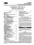
OUTLINES & DIMENSIONS
MODEL : MS(H)-O9DW- IU1/
INDOOR UNlT
1
10-11/16
Unit : inch
4
12-5/8
]\
Wall hole
st
Liquid line +1/4, 19-1 1/16 in.
Gas line +3/8, 16-3/4 in.
Insulation O.D. 6 1 2/16
Air outlet
MODEL : MU(H)-O9DW- lUll
OUTDOOR UNlT
REQUIRED SPACE
Drain hose 45/8
Insulation 0 . D. 4 1-3/ 16
I.D. 47/8
Ti?
Air intake
Air &et
/
Refrigerant pipe (Flared) 13/8
a
MODEL : MSH-1ZDN MSH-15DN
INDOOR UNlT
-
Unit : inch
3-1/2
L
Indoor unit
'
----
I
:
Installation plate
15-1/8
15
.
Wall hole
43
39-3/8
t
1
Installation
+7-4-@plate
Drain hose 45/8
--Wireless remote controller
l-iFh
la
3
insulation
&7/8
Air outlet
REQUIRED
MODEL : MUH-12DN MUH-15DN OUTDOOR UNlT
a
Air intake
n
Air odeti).
L
4 Installation anchor hdes
3 / 8 13/16
~
33-1/2
nit
center
13
CIRCUIT DIAGRAM -.
-I11:
t.
.
'
MODEL MS-OQDW-rn WIRING DIAGRAM
SKELETON WIRING DIAGRAM
pimmil
pimzzq
7
-
MODEL
MSH-OSDW-IU11 WIRING DIAGRAM
SKELETON WIRING DIAGRAM
pGEiq
piEmKJ
SYMBOL^I
NAME
C11
INDOOR FAN CAPACITOR
C61
COMP. CAPACITOR
C65
O W O R FAN CAPACITOR
ISYMBOL~
I
MF61
I
NAME
OUTDOOR FAN MOTOR
(INNER PROTECTOR)
NR11,61 VARISTOR
RT11
ROOM TEMP. THERMISFOR
NAME
SYMBOL
T I 1.61
Xll-14
X62
TRANSFORMER
INDOOR FAN RELAY
R.V.COIL RELAY
DSAR 11 INDOOR SURGE ABSORBER
FIT12
INDOOR COIL THERMISTOR
X63
SOLENOID COIL RELAY
DSAR 61 OUTDOOR SURGE ABSORBER
RT13
HEATER CONTROL THERMISTOR
21R
SOLENOID COIL
RT61
DEFROST THERMISTOR
2154
R.V. COIL
RT62
DISCHARGETEMP. THERMISTOR
FS
THERMAL FUSE (282'F 10A)
F11.61 FUSE (LA)
-
H
MC
MFl
HEATER
SEMI CONDUCTOR RELAY
COMPRESSOR MOTOR
TB1,3
INDOOR TERMINAL BED
INDOOR FAN MOTOR
(INNER FUSE)
TE2.4
OUTDOOR TERMINAL BED
52C
COMP. CONTACTOR
88H
HEATER CONTACTOR
-
SKELETON WIRING DIAGRAM
POWER POWER
SUPPLY SUPPLY
115V
208/230\1
60Hz
SlMsOL
C1l
NAME
SYMBOL
INDOOR FAN
CAPAMTOR
C61
COMP. CAPACITOR
C65
OUTWORFAN
CAPACITOR
INDOOR SURGE
ABSORBER
OUTDOOR SURGE
ABSORBER
F61
.
FS
~RISi378FlW
Fl1
INDOOR FUSE UlU
H
MC
MFl
MF61
MV
NRl1
NAME
60Hz
NAME
SYMBOL
SYMBOL
NAME
X64
OUTDOOR FAN R E L N
TB1.3
INDOORTERMINALBE0
21S4
TB2.4
OUTDOOR TERMINAL
BED
NU61
OWDOORVARlSrOR
SWl
HEATER
RTtl
COMPREWR MOTOR
RTlZ
ROOM TEMP.
THERMISmR
INDOOR 'OIL
THERMISTOR
VANEMOTOR
INDOOR VARISTOR
NAME
VANESWITCH
SYMBOL
OLITWOR F U S E ( W
INDOOR FAN MOTOR
(INNER FUSE)
OUTDOOR FAN MOTDA
(INNER PRorrCmR)
1
w T11.61
~
TRANSFORMER
~
R
o
L
RT13
~
RT61
%!%?&OR
RT62
~ ~ ~ ~ M ~ $ & w '
X16
VANE MOTOR RELAY
SSR61
&W:aR
RuAY
X62
R.V. COIL RELAY
~
~
~
INDOOR FAN RELAY
R.V COIL
THERMAL OVERCURRENT RELAY
52C
st>
COMP.MNTACTOR
HEATER CONTACTOR
Fl REFRIGERANT SYSTEM DIAGRAM
Indoor unit
1
Refrigerant pipe 63/8
(Option)
(with heat insulator)
Fusible plug
1
$allvalve
connection
\
Room t e m d
I
I
Accumulator
-
efr,gerant pipe 1/4 Ball valve Capillary tube (60.12 x (6 1/16 x 47-1 /4
with senrice
(Option)
(with heat insulator)
POrt
Refrigerant pipe 63/8
(Option)
(with heat insulator)
4-way valve
--
Flared connection
thermistor
RTl 1
II
Compressor (
I-
R.V. coil
heating ON
cooling OFF
2-way
--..(Option)
(with heat insulator)
polt)
-
40.12~1/16~35-7/16
Strainer
a low of refrigerant i d i n g )
---*Flow of refrigerant (heating)
---
Heater
control
thennintor
RT13
Room temp.
themiistor
RTl 1
Flared connection
(Option)
(with heat insulator)
port)
-
-
Capillary tube
MSH-12 : 60.12xd1/16~3-15/16
MSH-15 : 6 0 . 1 2 x ~ 0 . 0 7 1 ~ 3 - 1 5 / 1 6
----.
Flow of refrigerant (cooling)
Flow of refrigerant (heating)
Wireless Remote Controller
SENDING SECTION-)
Once the controls are set, the same operation mode can be
repeated by simply turning the POWER switch ON.
MASTER CONTROL Indoor unit receives the signal with a beep tone.
bunon
When the system turns off, "3 min. tim&elay function" will
operate to protect system from over load and compressor does
FAN CONTROL
not restart before 3 minutes.
LCD
INDICATOR
bunon
SET TEMP.
bunon
TIMER CONTROL
bunon
TIME S€lTtNG
bunon
VANE CONTROL
I FEEL CONTROL
bunon
TOO COOL
OKAY
TO0 WARM
bunon
-Con
1. "I FEEL CONTROL" operation
(1) Press POWER button on the remote controller. Power
lamp of the indoor unit will tum on with beep tone.
(2) Select the MASTER CONTROL button to "I FEEL
CONTROL". And I FEEL MONITOR lamp lights with
beep tone.
(3) The operation mode is decided by the initial room
temD. at startina
- up
. the operation.
Initial Room Temp.
POWER
bunon
COOL mode of
"I FEEL CONTROL"
73'F to 76°F
DRY mode of
"I FEEL CONTROL"
MGDW
: 5 5 ' ~to 76F
less than 73'F
I
HEAT mode of
I MSH-09.12.15 1 "I FEEL CONTROL" I
*Once the mode is fixed, the mode will not change by
room temp. afterwards.
*Under the AUTO START timer operation, the mode is
determined according to the room temperature 1 hour
before the set time.
When the system is stopped with the POWER button on
the remote controller, and restarted within 1 hour in "I
FEEL CONTROL" mode, the system operates in previous
mode automatically regardless of the room temp.
more than 7 6 F
I
MSH-12/15DN- Q
I INDOOR UNIT DISPLAY SECTION
POWER
When the system is restarted after 1 hour, the operation
mode is decided by the initial room temp. at starting up the
operation.
DEFROST
IDDOI
MSH-09DW
I FEEL MONITOR
Example
Previous operation
I
FEEL MONITOR
I
I
COOL mode of
"I FEEL CONTROL"
or COOL mode
i
OFF
MSH-12/1IDN
9
1 hour
I
i
Restart
COOL mode of
"I FEEL CONTROL"
ON
(4) The initial set temp. is decided by the initial room temp. within 2 min. after starting-up the system.
I
Mode
Initial set temp.
initial Room Temp.
# 1 After the system restarts by the remote controller, the system operates with the previous set temp. regardless of the
initial set temp.
E2 By room temperature compensation of 4 deg, room temperature of a living space is 75°F.
(5) 1 FEEL CONTROL buttons
In "IFEEL CONTROL" mode, set temp. is decided by the microprocessor based on the room temp. In addition, set temp.
is controlid by I FEEL CONrROL buttons when you feel too cool or too warm, and when you feel comfortable the &
button foces the comfortable temp.
When the I FEEL CONTROL bunon is pressed, I FEEL MONITOR lamp on the indoor unit pulsates for a second with beeps.
Variable control
1W COOL
TOO WARM
When the 0
or 0
button is pressed, the set temp. is changed based on the room temp. As the set temp. range
is variable, this is called "Variable control". The variable control operates only in "I FEEL CONTROL" mode.
In DRY mode of "I FEEL CONTROL". the set temp. range is fixed
2 deg ("F).
+
i e j--To raise the set temp 2 deg.
OKAY
-
5 deg. (.F)
..+To fix and memorize the comfortable present temp.
0
Too WARM...~o
lower the set temp. 2 deg.
0
-
5 deg. ("F)
Over shoot control
when1=button
(or'=
button, when heating) is pressed one or two I FEEL MONITOR lamps light, the indoor unit
operates to get lower (or higher, when heating) temp. than the set temp. temporarily ( 6 0 sec.) by the microprocessor
control. This is called "Over shoot control".
when1=
button is pressed during COOL mode of "I FEEL CONTROL", the tempera6tre change is as follows.
Room temp.----
6 deg.
-
('F)
Set temp.
MSH-09,12,15
When 100 COO'
button is pressed during HEAT mode of "I FEEL CONTROL" the temperature change is as follows.
Set temp.
6 deg.
Set temp. range MAX. 5'F
Room temp.
button is pressed during COOL mode of "IFEEL CONTROL" an4
The over shoot control does not operate when
1W WARM
button is pressed during HEAT mode of "I FEEL CONTROL".
20
- I FEEL MONITOR lamp on the indoor unit When I FEEL CONTROL button is pressed, I FEEL MONITOR lamp on the indoor unit pulsates with beeps and shows the temp.
control condition.
I FEEL MONITOR
lamp
\I \/ ,I
Shows difference between Set temp. and Room temp. is more than 3 deg. ('F)
During this condition, I FEEL button is not available.
Wait for about 15 min.
Shows dierence between Set temp. and Room temp. is 2 deg.
3 deg. ('F)
The buttons are available.
D D ~
Shows Room temp. is almost Set temp. The difference is less than 2 deg. ('F)
The buttons are available.
NOTE 0 During "I FEEL CONTROL" operation, thermostat (SET TEMP.) is not available. Use "I FEEL CONTROL"
buttons to set temp.
*Once the set temp. is set, the microprocessor memorizes the temp. and the system restarts at the same set
temp.
88°F in COOL DRY HEAT mode of "IFEEL CONTROL".
*The set temp. range is 61
0 When the main power is turned off, the settings are canceled. Set temp. will be initial set temp. again. See
page 20.
- COOL mode of "IFEEL CONTROL" -
-
D?@
-
Compressor &
Outdoor fan motor
Indoor fan motor
OFF
ON
j
I
OFF
I
Runs all the time in cooling mode
NOTE Coil frost prevention during COOL mode of "IFEEL CONTROL"
.When the indoor coil thermistor RT12 is below 47'F for MS-09, 37'F for MSH-09, 27'F for MSH-12/15
for 5 min. the coil frost prevention mode starts. The compressor stops for 5 min. and the indoor fan runs
at set speed. The coil frost prevention mode may continues past 5 min. untill the indoor coil thermistor RT12
exceeds 47'F for MS-09, 37'F for MSH-09, 27°F for MSH-12/15.
The first 5 minutes, termination of Coil Frost Prevention is controlled by time regardless of the termination
temperature. After that the termination is controlled by the temperature regardless of time.
Therefore, Coil Frost Prevention continues at least 5 minutes even if the temperature reaches termination
point within 5 minutes. After 5 minutes, Coil Frost Prevention terminates if the temperature reaches to
termination point, or the mode will be prolonged untill the temperature reaches to the termination point.
Indoor fan operates at the set speed by FAN CONTROL switch.
Followings are the fan speed in AUTO.
7 deg. ('F) .-HI
Room temp. minus Set temp. : more than 4
MED
Room temp. minus Set temp. : 4 deg. ('F) to 7 deg. ("F)
3 deg. (OF) ...--LO
Room temp. minus Set temp. : less than 2
- DRY mode of "IFEEL CONTROL" The system uses the same refrigerant circuit as the cooling circuit for dry operation.
The compressor and the indoor fan are controlled by temp. and by the microprocessor.
By such controls, indoor Row amounts will be reduced in order to lower humidity without much room temp. decrease.
The operation of the comp. and indoor fan is as follows on the next page.
-
--
Compressor operates by temperature control and time control.
In the first 2 min. the system is FAN mode and the indoor fan operates at VLO speed.
Then 2 min. later, the room temperature is read as the initial temperature.
@Set temp. is controlled to minus 2'F as initial set temp.
@When the thermostat is ON, the compressor repeats 8 min. ON/3 min. OFF cycle operation.
When the thermostat is OFF, the compressor repeats 4 min. OFF/1 min. ON cycle operation.
lndoor fan and outdoor operate in same cycle with compressor.
Indoor fan speed is VLO.
Operation Time Chart
1
1st ON
Example
Thermastet
OFF
!
Indoor fan
VLO speed
ON
ON
OFF
ON
OFF
ON
Outdoor fan
cornpresrror
:
OFF
j
:
i
i
1
2 8rnin. :
:
OFF
m
ON
:
I
OFF
ON
.., .,,
ON
:
I
.,.. .,.
.,
, *
#
I
I
,
7
i
NOTE *Coil frost prevention during DRY mode of "I FEEL CONTROL"
The operation is same as coil frost prevention during COOL mode of "I FEEL CONTROL" except the indoor
fan speed is VLo.
*In DRY mode of "I FEEL CONTROL", FAN CONTROL switch is not available.
- HEAT mode of "I FEEL CONTROL" 1. Indoor fan speed control
(1) Following are the fan speed in AUTO.
Temperature condition
Fan speed
HI
7 deg.
Room temp. minus set temp. : more than 4
7 deg. ..............................MED
Room temp. minus set temp. : 2
3 deg. ............-..LO
Room temp. minus set temp. : less than 2
(2) Cold air prevention control
The defrost lamp lights by the fan control.
The fan runs when the indoor coil thermistor RT12 temp. exceeeds 7TF, when the temp. is below 64F, the fan stops.
(3) New warm air control.
When compressor starts in heating operation or after defrosting, the fan changes the speed due to the indoor coil
thermistor RT12 temp. to blow out warm air.
After releasing of cold air prevention, when the indoor coil thermistor RT12 is 113'F or above, the fan speed shifts to the
set speed.
When the indoor coil thermistor RTI2 is less than 113F, the fan speed is controlled by time as below.
Time condition
Indoor fan speed
less
than 4 min......................... Lo
4 min. to 8 min. ........................ MED
more than 8 min.
HI
The upper limit of the fan speed is the setting speed.
If the thermostat turn off, this operation changes to flow soft control.
(4) Flow soft control
After a compressor turn off by the thermostat, the indoor fan operates at a lower speed than LO.
NOTE :This speed is called Very Low (VLO) in this manual. When the compressor runs, the fan operates at the setting
speed. Due to the cold air prevention control, the fan does not start until the indoor coil thermistor RTI2 temp.
exceeds 72'F.
(5) If turn off the POWER button during heat operation, the indoor fan operates for 30 sec. LO speed to eliminate heat.
-
-
............
C
........................
2. High pressure protection
During heating operation the solenoid valve for injection and the outdoor fan motor are controlled by the temperature of the
indoor coil thermistor RT12 for excess rise protection of compressor discharge pressure.
This high pressure protection control is as below.
Outdoor fan
Model
ON
OFF
121'F
126F
MSH-OSDW
117'F
122'F
MSH-12DN
127°F
133°F
MSH-15DN
High pressure protection time chart
Indoor coil tlwmktw
RT12 MSH-09 MSH-12 MSH-15
126F
722'F
733'F
'
121'F
117'F
127'F
115'F
-
-
lnjmim m
turn
Outdoor
OFFfan motor
I
Outdoor fan motor
turn ON
Injection sdenoid coil
turn OFF
injection sdenoid
mii ON
d wit
Outdoor fan motor
11
'
NOTE : When the outdoor fan is off, the heating defrost is not detected bv the defrost thermistor RT61.
Defrosting
Outdoor unit defrosting is controlled by outdoor P.C. board, it is detected by the defrost thermistor RT61 and discharge temp.
thermistor RT62.
Defrost starting conditions
When all conditions of a) -- dl are satisfied, the defrosting operation starts.
a) Under heat mode of "I FEEL CONTROL" and heat operation, the compressor cumulative time exceeds the defrost interval.
b) The defrost thermistor RT61 is below 27°F.
c) After releasing the high pressure protection of the outdoor fan operation, 180 sec : MSH-OSDW or 256 sec : MSH-12/
15DN elasped.
d) Regarding MSH-12/15DN, discharge temp. ttiermistor RT62 is below 185°F.
Defrost stopping conditions
When the condition e) or f) is satisfied, the defrosting operation stops.
e) The defrost thermistor RT61 is above 37°F.
f) The defrosting time exceeds 1 0 min.
The defrosting operation stops forcedly by timer.
Defrost interval
The defrost interval is calculated by defrosting time.
1. After starting of heating operation, the first and second defrost interval are fixed t o 6 0 min.
2. From the third interval, it is calculated so as that defrost time is 2 min.
Time
I underDefrost
2 min.
-
2
-- 3 min.
3
4 min.
I
Defrost Interval
Previous interval plus 1 0 min.
Same as previous
Previous inteml minus 1 0 min.
Previous interval minus 2 0 min.
over 4 min.
3. Max. and Min. of Defrost Interval
Max.
Mode
Min.
1
MSH-OSDW
I
MSH-12DN
MSH-I5DN
120 min.
4 0 min.
2 0 min.
I
Defrost time chart
Defrost thermistorI - *
37'F
I
-
.
2 min.
I
I
I
I
I
I
4 deg.
Set temp.
I
I
I
f
!
1
I ON
I
I
I
I
I
I
I
Defrost lamp
-pressor
-
I
I
I
OFF
!
I
I
I
I
1
I
I
I
ON
ON
j
,
8
II
I
w
I
,
I
,,
I
I
I
I
OFF
I
I
I
I
I
I
I
R.V coil
ON
I
I
i
r
I
!
Max. 10 min.
I
I
I
I
t
,
I
I
I
1
I
I
I
I
I
I
I
I
I
I
I
I
I
Outdoor fan motor
I
I,
I
I
1
I
I
I
I
8
1
1
I
I
I
I
I
I
'
I
I
I
I
I
I
I
I
I
8
Ia
I
I
I
I
@&on sobndi coil
I
I
I
I
,
I
I
I
I
indoor fan motor
ON
I
I
I
I
I
II
I
I
I
I
I
I
tI
I
I
,
I
Defrost counter
I
I
I
OFF
I
-
I
8
Defrost
preoperation
Auto vane position
I
,
I
I
:
-I
I
I
I
I
I
I
:
1
8
I
I
I
I
0
I
t
I
i
I
1
c
I
I
'
'
I New warm
;*
I
;
I
:
4
I
I
I
1 air control
I
;
,
I
I
I
I
I
I
I
i
I
1
1
:I
#
1
I
I
I
1
,
1
I
I
I
I
I
I
I
I
I
f
I
I
I
:
I
I .
I
I
I
I
I
I
I
I
(2)
;
I
I
I
I
!
1
I
I
1
*
I
:
I
I
a
,
I
-
Cold air.
M m
P
---------- :----
l i
'
!
I
I
iI iI ON
I
,
I
II
I
I
I
I
I
I
!OFF
I
II
I
o Defrost interval
1
I
'
I
I
(2)
I
I
I
I
1
1
I
i
,
I
I
I
I
The vane is controlled by
indoor thermistor RT12
after this line.
i
4. Heater control
(1) When all listed conditions are satisfied and 3 0 sec. elasped, power is supplied to the heater.
O l n heating mode
@Indoor fan speed is faster than LO.
@Room temp. thermostat is on.
@By temperature of Heater control thermistor RT13
ON
OFF (Heater ON/OFF)
131'F
140F
MSH-O9DW
142'F
151°F
MSH-12/15DN
@By differential between set temp. and room temp.
5 deg. ('F) : ON, below 4 deg. ('F) : OFF
@Not in heating defrost mode
(2) If one of above conditions are not satisfied, the heater tums off.
owhen system is stopped by pressing the power button, the indoor fan operates for 3 0 sec. in LO speed to eliminate
the remaining heat.
owhen the room temp. thermostat is off, the indoor fan operates at VLO (Very LO) speed.
(3) Power is not supplied t o the heater under following condition even if ail above condions are satisfied.
o w e n the in&mr coil, thermistor RT12 is over 1 0 4 F and the heater control thermistor RT13 is disconnected.
5 . Discharge Protection
When the discharge temp. is too high because of unit gas leakage or other reason, the discharge temp. thermistor RT62
stops compressor in order t o protect compressor from burning.
MSHO9-DW
MSH-12DN
Discharge protection operates in "I FEEL CONTROL", COOL, DRY, and HEAT mode.
2. COOL operation
(1) Press POWER button.
Power lamp of the indoor unit tums on with a beep tone.
Indoor fan continues to operate regardless of thermostat's OFF-ON.
Coil frost prevention is same as COOL mode of "I FEEL CONTROL".
(2) Select COOL mode.
(3) Set the SET TEMP. button.
The setting range is 59 -- 89'F.
*"IFEEL CONTROL" buttons are not available.
3. DRY operation
(1) Press POWER ON/OFF button.
Power lamp of the indoor unit tums on with beep tone.
(2) Select DRY mode.
(3) Indoor fan operates at VLO speed.
(4) After 2 min. the microprocessor reads the room temp.
and decides the set temp. Set temp. will be as follows.
65
70
75
80
85
Initial room temp.
90
95
Thermostat (SET TEMP.) is not available. The other operations are same as DRY mode of "I FEEL CONTROL".
100'F
25
4. HEAT operation
(1) Press POWER button
POWER lamp on the indoor unit tums on with a beep tone.
(2) Select HEAT mode.
DEFROST lamp on the unit lights during the cold air prevention control.
(3) Press SET TEMP. button to select the desired temperature.
The setting range is 59
89F.
"I FEEL CONTROL" button are not available.
(4) Indoor fan speed control, hight pressure protection, defrosting, heater control are same as HEAT mode of "I FEEL
CONTROL".
-
5. FAN operation MS-O9DW
(1) Press POWER ON/OFF button.
(2) Select FAN mode.
(3) Press SET TEMP. button to select the desired temperature.
The indoor fan stops when room temperature is lower than the set temp.
(4) Select the desired fan speed.
Followings are the fan speed in AUTO.
7 deg. --.HI
Room temp. minus set temp. : more than 4
Room temp. minus set temp. : 2 -- 7 deg:.-.......--..-.---.-.---MED
Room temp. minus set temp. : - 2 -- 3 deg....-........--...-..-LO
0 deg. --..STOP
Room temp. minus set temp. : less than - 2
Only indoor fan operates.
Outdoor unit does not operate.
-
6. TIMER
1. AUTO STOP operation
AUTO STOP mode has "SOFT SLEEP" citcuit which provides
comfortalbe temperature control for sleeping.
(1) Select the TIMER CONTROL to AUTO STOP.
(2) Set the time. Time setting is 1 hour unit for 12 hours
(3) "SOFT SLEEP" circuit operates in COOL and HEAT mobe. By this
circuit, system operates at the set temp. for the first 1 hour. Then,
in COOL mode the set temp. raises by 1 deg. haw- hourly to 2 deg.
range and in heat mode the set temp. falls by 1 deg. half-hourly to
4 deg. range.
In "I FEEL CONTROL" and DRY mode, the circuit does not operate.
2. AUTO START operation
(1) Select the TIMER CONTROL button to AUTO START.
(2) Set the time. Time setting is 1 hour unit for 12 hours.
13) In HEAT mode, warming up circuit operates.
--
NOTE TIMER setting will be canceled by power failure
Breaker Functioning.
7. AUTO VANE adjustment MSH-12DN
MSH-15DN
(1) The vane circuit / Auto vane direction
position '2,
The vane motor circuit
60'
90
:
Auto vane direction
(2) Vane control
Automatic control (Auto vane lamp is on.)
0 During COOL operation
The vane is at position '1 J initially
power ON
moves to position '2J retums to '1 J
0 During HEAT operation
Power ON the vane moves to position '2J
moves to '1 J
ountil the temp. of lndoor coil thermistor RT12 rises to 97°F : position '1 J
(on the indoor heat exchanger)
owhen the thermistor temp is 97'F : changes position '1 J *'2J
OUntil the temp. of lndoor coil thermistor RT12 falls to 86F : position '2J
(on the indoor heat exchanger)
owhen the thermistor temp is less than 86°F : changes position '2J -+'I
J
When contactor (52C) is off : position 1J
0 During defrosting : the vane is forced to return to position '1 J
The indoor fan speed is VLO while the vane is working.
+
+
-+
fixes on '1 J
-+
+
'
When thermistor (RT12) is 8.6F or below
Comp. contactor (52C) is off.
I
6W
90
'23
When Thermistor (RT12) is 97'F
or above.
lndoor coil Thermistor RT12 temp.
EMERGENCY-TEST operation
When the remote controller is missing, has failed or the batteries run down, set the emergency run selector switch on the
front of the indoor unit to heat or cool and press the emergency run on/off switch. The unit will start and the operation lamp
will light.
The first 30 min. of operation will be the test run operation. This operation is for servicing. The indoor fan runs at high
speed and the system is in continuous operation. The thermostat does not operate and the timer is reset to normal.
After 30 min. of test run operation the system shifts to emergency run operation with a set temperature of 75°F in heating
or cooling. The fan s h i to MED speed.
This operation continues until the emergency run on/off button is pressed or a button on the remote control is pressed, then
normal operation will start.
The coil frost prevention circuit operates in this mode.
-
EMERGENCY RUN
COOL
I
EMERGENCY
ONIOFF button
9. AUTO RESTART FANCTION (Optional)
How to restart units after power failure by Auto Restart.
ONNErnOR NO.
Model
1,
MS-09DW-
rn
MSH-O9DW-
rn
MSH-12DN- [CTil
MSH-15DN- QJ
1
CNl25
CN 105
CN107
1
MrnOD
Short the connector 5 - 7 on the electronic control P.C. board for connector
position, refer to page 38.
1
Short the connector 1 - 3 on the electronic control P.C. board.
For connector position, refer to page 40 for model MSH-O9DWmodel MSH-12/15DNSet the emergency run switch to "COOL" or "HEAT"
a.
rnor page 43 for
Operation
When power is restored the unit will operate in the emergency-test run mode. Even if the unit is turned off at the thermostat,
The heat or cool mode will be determined by the position of the emergency-test run
it will come on after a power failure.
selector switch. When a button on the remote contoller is pressed the unit will return to normal operation as the controller
has priority. See page 27 for emergency-test run operation.
lO.COMPULSORY DEFROSTING MODE FOR SERVICE
Defrosting mode can be accomplished regardless of the defrost interval restriction by short-circuiting the connector
(CN606) on the outdoor P. C. board which is located in outdoor unit.
This compulsory defrosting mode should be started by the pulse based on the temperature sensed at the defrost thermistor
*
( R T1~) . Therefore,
as far as RT61 senses higher than 27'F, the compulsory defrosting mode connot be achieved.
RT61 is attached to the outdoor heat exchanger. See page 42 and 45 for the position of the connector CN606.
*
Self check function
This function is to show defective point by lighting or flickening of the indoor unit power lamp, defrost lamp, or "I FEEL"
monitor lamp (monitor LED). If troubles written in the below table occur during operation, the self check result indicated. The
abnormal point indication disappears by pressing the power on/off button of the remote controller and when the unit is on.
*Before taking measures make sure that the symptom reappears, for accurate troubleshooting
Self Check Table
Abnormal point
POWER DEFROST
Serial signal
:m. '
a:
1.When serial signal from
outdoor unit stops for 4
-- 5 sec.
Flash
Cause
Detect method
Indication
1II:
OFF
Measures
I
lndoor Outdoor connection mis-wiring
Indoor Outdoor connection disconnecting
Connector rnisconnecting
Indoor electronie control
p.C. board defect
Outdoor P. C. board defect
Electrical parts defect
Check wiring (Visual
check and conductivity
check)
Check indoor board
Check outdoor board
Check electrical parts
lndoor unit power 2. Detects lndoor coil thermis- @Thermistordefect
Connector disconnecting
tor short or open circuit
turns off.
Connector misconnecting
every 2 sec. during operaindoor control P. C. board
tion.
defect
Check thermistor charactor
Reconnect connector
Reconnect connector
Check indoor board
Compressor no 3. Detects Discharge thermis- @Thermistordefect
Connector misconnecting
rotating
tor open : more than 10
Outdoor P.C. board delndoor unit
min. later from compressor
fect
power tums off
starting up.
Detects Discharge thermistor short : During Compressor operation.
Check thermistor charactor
Reconnect connector
Check outdoor board
Outdoor unit
does not run
D D O
I FEEL MONrrOR
When serial signal stops for
set. after Ist
On Of
52C relay by POWER turning on.
'
lndoor coil
temp.
thermistor
Steady
Outdoor
thermistor
(Discharge
RT62)
MS-09 has only N0.2 check function.
'
(1) Operation does not start
MS-O9DW
MSH-OSDW lUll
-
-
Check power supply voltage on indoor
terminal bed.
Is there 115V AC between indoor
terminal bed
?
No
c Turn on power supply
-
Does+signal mark display for an instant
on Remote Controller when POWER button
pressed?
No
1
\
Is Batteries voltage
over 2.4V ?
Yes
No
Does emergency run start by
pressing EMERGENCY button 7
----"-I
tes
Replace Remote
I
Chedc voltage of control circuit
on Electronic control P.C. board.
Is there IOV DC between connector
for MSH-09.
CNlOl (pow) @+) @-) for MS09, @+) @-I
See the TEST POINT DIAGRAM VOLTAGE on page 38 for MS09, page 40
for MSH-09.
-
I
\
Does indoor unit receive siganl
with a beep tone when WWER
button pressed ?
.
Replace Electronic
control P.C. board.
ko
/
I
-
I
Redace Receiver board.
Power P.C. board.
*
J
9
(2) Operation does not start.
MSH-12DN
MSH-15DN
-
-a
"\
Check continuity of connector;
when you check to voltage.
1
Check power supply voltage on indoor
terminal bed.
Is there 115V AC between indoor terminal
beda-a?
No
Yes
Power supply turn on
.
Check primary voltage of transformer
on power P.C. board.
ISthere 1 15V AC between connector
,CN204 @ - @ ?
T
*
*
No
Check secondary voltage of transformer
on power P.C. board.
Is there 13V AC between connector CN204
No
Check fuse.
if no good, replace Fuse ( F l l ) .
-
Redace
Transfonner(T11)
Yes
Does emergency run stan by
pressing EMERGENCY button ?
No
m
- @R
EIecmxliicontrol P.C. board
and power P.C. board.
-
signal mark display for an instant
Does
on remote controller when POWER
button pressed ?
No
Replace the batteries.
-
Replace remote controller.
I
Indoor unit receive signal with
a beep tone when WWER button
pressed?
I
No
Replace Receiverboard.
i
-
(2) Outdoor fan does not operate (compressor operates)
MSH-OSDW
MSH-12DN
MSH-15DN
Below listed are not troubles
1. Heating defrost
During heating defrost operation, the outdoor fan stops. Refer to defrost time chart on page 24.
2. High pressure protection
During heating operation, when high pressure protectionworks the outdoor fan stop. Refer to high pressure protection tim
chart on page 23.
- lUl
- lUl
t
Is ther 1 15V AC for MSH-09, 208/230V AC for MSH-12/15
between Mack - ~
t connector
e
CN711 of outdoor fan
motor
O
Yes
Check outdoor
fan motor.
w
Q
No
(Coding) NO
Heating operation ?
I
Yes (Heating)
High pressure protection
condiin
Normal
No
Yes
Defrosting condition
r
1
Normal
PI'*
3. Compressor does not operate (Indoor and outdoor fan operates)
MSH-OSDW lUl
MSH-12DN lUl
MSH-15DN lUl
-
-
[Noticel
Check continuity of connector,
when you check to voltage.
Pn?ss EMERGENCY ON/OFF button
3 rnin. timedelay function operates
Test mode operates for 3 0 min.
Check voltage to Contactor 52C.
Is there 12V DC between connector
CN720
@-I on outdoor P.C. board ?
No
Replace OutdoM P.C. board
a+)
-
\
I
Yes
I
Check voltage compressor terminal.
Is there 1 15V AC for MSH-OQDW, 208/230V
for MSH-12/15DN W e e n compressor terminal
C-R?
+
Check Contector 52C
and thermal ovenxlW reiay.
Ifnogoodr@-per*;.
Compressor and outdoor fan do not operate (Only indoor fan operates)
MS-OSDW-
I
I
Press EMERGENCY ON/OFF button.
3 min. timedelay function operates.
Test mode operates for 30 min.
i
isthere 115~~~bennreen&l - a o f
outdoor terminal bed 7
No
+
Turn on outdoor
Power ~ p p h / .
Yes
Check voltage to contactor 52C.
Isthere12VDCbeMreenUJ-C[]of
outdoor terminal bed 7
No
-P
Check Contactor 52C.
If no good repiace
Contactor 52C.
b
Check continuity of
indoor and outdoor unit
connection.
I No
Isthere 12V DC between m+l
indoor temdnal bed 7
- @-I
Yes
of
;
No
1
No
Check resistance of room temp. thermistor RT11.
See the thermistor resistance on page 38.
Yes
t
I
1
Replace Indoor ektrork control
P.C. board.
1
b
Replace Room temp.
thermistor RTl1.
i
i
4. Heater does not work. (compressor and fan operate)
MSH-OSDW IU;I1
-
t
Heating selected ?
Is blow out air temp.
140' F for MSH-OSDW
151'F for MSH-12/15DN or below ?
Is set temp, minus room temp.
larger than 5°F ?
Check voltage to heater.
Is there 115V AC between heater
connector
- CJ] 7
Yes
I
t
Is there continuity to
fuse (FS) ?
Replace fuse (FS)
of heater assembly
I
Yes
Is there continuity to
heater (H) ?
I
/
Check voltaae to heater contactor 88H
for M S H - O ~ D W - ~or
1 88H1. 88H2,
for MSH-12/15DN-Ul.
Is there 12V DC betweeen heater contactor
\
I
No
Yes
Replace Electronic control P.C. board.
I
i
Replace Heater contactor
88H or 88H 1, 88H2.
Check resistance of heater control
thermistor RT13.
See the thermistor resistance on page 40, 43.
I
Replace heager (H)
N m l
1
0
I
Replace Heater control
thermistor RT13.
I
5. Heating operation does not work. (Cooling operation works)
MSH-OSDW
MSH-12DN
MSH-1SDN
I
- JU11
- lUl
- JU11
I
Set the SELECTOR to HEAT.
Ress the EMERGENCY ON/OFF button.
Yes
\
I
Check voltage R.V. coil.
Is there 115V AC for MSH-09. 208/23W AC
for MSH-12/15DN betwem connector CN72 1
@ Q on wtdoor P.C. b o d 7
-
Yes
I
I
No
b
Replace Outdoor P.C. board.
3
RELAY OPERATION
MS-O9DWMSH-O9DWMSH-12DN- DI
MSH-15DN-
I
a
AUTO or set speed
For 2 min. is OFF, when
DRY &
DRY mede of
I FEEL CONTROL
VLO speed.
system tum on first.
ON
*
ON
3 min. OFF operation
VLO links with 52C contactor.
OFF
Repeats 4 min. OFF 1
min. ON operation
ON
ON
AUTO or set speed.
OFF
OFF
VLO speed
I
HEAT & HEAT
mode of I FEEL
CONTROL
MSH-09/12/ 15
ON
FAN
MS-09
AUTO or set speed
OFF
OFF
OFF
NOTE : When the compressor is OFF, "3 min. time-delay circuit" operates.
COIL FROST PREVENTION mode are as follows
62C CONTACTOR
THERMOSTAT
MODE
I
OFF for minimum 5
min. after 5 min. pas-
COOL &
COOL mode
of I FEEL
CONTROL
sed, remains off until
indoor coil thermistor
termination temp.
When indoor coil thermistor temp. reach termination temp. it turns
on.
DRY &
DRY mode of
I FEEL
CONTROL
...&
Indoor fan relav mode
1 Indoor fan weed I
I
I
HI
i
-
LO
VLO
OFF
Relav'tuming ON
I
X14 for MS-09 and MSH-09
X I 5 for MSH-12/15
I
X12
Xl1
1
All fan relays are turn off
Auto or set speed
VLO speed
I
TEST POINT DIAGRAM AND VOLTAGE
MS-OSDW@~~
Electronic contol P.C. board
s.wr,,
Themistor RTl 1
60
70 7780
90
Temperature ('F)
I
CN~OI
POW1
3
-
Auto restart conneaor
Shorten the connector CN 125
betweeno-0
10V DC power supply of control circuit
5V DC reference voltage
----- dock signal circuit
Temperature ('F)
100
MS-OQDW-/U11
Power P.C . board
ll5V AC
Indoor fan mator
mltasa
1-aFan connector
Electronic control P.C. board
4'
10V DC Power supply of
control circuit
ON : 12V DC Heater contactor
OFF : OV DC
Power P.C. board
F
-
*I
1%
f', s!
:m
ii
-
r'
L
(
.I
l l 5 V AC
Indoor fan motor
voltage
Defmst thermistor RT6 1
Discharge temp. thtWtllii RT62
R.V. wil
ll5V AC
Compulsory defrost terminal
CN606
-
Solenoid coil
115V AC
Outdoor fan motor
1 15V AC
BLK~BLK
w1-1~21JBLKB
Electronic control P. C. board
4uto restart
mnector CN107
shorten me connector
D-Q
-
-Room temp.
thermistor RTl 1
-
-Indoor coil
thermistor RT12
- Heater control
thermistw RT13
Discharge temp. mennistor RT62
Temperature CF)
-IBLK
BLKI
R.V. coil
208/230V
Outdoor fan motor
208/230V AC
C
INDOOR UNIT PARTS
(WG,SW)
MS-OSDW-
a
MSH
L
1
L
1
VOL AZ8Z
-
WEIZL-MZS
VB8Z 1-MZS
1
L
L
L
L
L
1
L
L
1
1
1
L
L
L
L
1
L
L
L
1
L
Z
1
1
Z
L
1
1
1
L
1
L
Z
L
Z
L
L
L
Pl
L
1
1
L
L
1
1
1
Pl
1
1
1
1
1
L
1
1
1
L
1
1
1
1
1
1
L
Z
EBl
181
18 1
l!my l!l
L
L
Z
l
1
Z
L
L
L
1
L
1
1
z
L
Z
L
L
PL
L
L
PL
L
1
1
L
L
1
1
L
1
L
Z
1
H88
SJ
H
EL l t l
Z lltl
ZLltf
1L l U
llltl
1 13
1
1
L
1
L
PI
1 LX
MX
ilx
W!L
L LJ
1 LJW
LLJW
L
Z
Z
L
1
MS
syerua'
DM
~n
MS
1
DM
Ln
Ma6WHSW Ma6O-SW
l!un/m
t l 3 D N V H 3 H 1-H tlOOaNl
tl3DNVH3H l V 3 H tlOOaNl
t l 0 1 3 V l N 0 3 tl31Q3H
3SnJ l V W t l 3 H l
tl31WH
t l O l S I W t l 3 H l l O t l l N 0 3 831-H
tlOlSIWtl3Hll103 kiOOaNl
tlOlSIWtl3Hll103 HOOaNl
tlOlSIWtl3Hl 'dW31 WOOtl
tlOlSIWtl3Hl 'dW31 WOOtl
tl0113VdV3 NVJ 8OOaNl
a t l V 0 8 '3'd H3A1333tl
a t l V 0 8 '3'd H311MS '8 AVldSla
atlVO8 '3'd H U M S % AVldSla
XOB d W V l
(tl00aNI) a 3 8 lVNIWtl31
(tl00aNI) a 3 8 lVNIWtl31
(ti00aNI) a 3 8 lVNIWtl31
a t l V 0 8 ' 3 ' d tl3MOd
CltlV08 ' 3 ' d tl3MOd
tlOlSltlVA
(VZ) 3SnJ tlOOaNI
a t l V 0 8 '3'd l O t l l N 0 3 13313
a t l V 0 8 '3'd l O t l l N 0 3 13313
lNnOW DNltlW8
DNltiQ38 3,4331s
NVJ M o l d 3 N I l
NVJ M O l J 3NIl
l N n O W 13388ntl
UOlOW NVJ tlOOaNl
tlOlOW NVJ tlOOaN1
a t l v n ~NVJ
( U S ) 3NVA 3CllflD
A18W3SSV 3lZZON
AlBW3SSV31ZZON
3SOH NlVtla
3 1 M d NOllVllVlSNI
Al8W3SSV X 0 8
Al8W3SSV XOB
(MS) 3NVA 3DNVH3
(DM) 3NVA 3DNVH3
tl3lllJ
(MS) Al8W3SSV 13NVd l N O t l J
(DM) A18W3SSV 13NVd l N O t l J
(MS) A18W3SSV 13NVd l N O t l J
(DM) Al8W3SSV 13NVd lNOUJ
OZ9
OZ9
ZPE
Z8E
O8E
80E
LO6
80E
80E
LO&
09E
899
6ZE
6ZE
6ZE
9LE
PLE
9LE
OW
OW
99P
Z8E
0SP
09P
609
PO9
ZOE
ZOE
909
OOE
OOE
190
OW
9EZ
9EZ
EOL
0L6
PEZ
PEZ
WO
OtrO
OOL
000
000
000
000
09P M Z l
9LP M Z l
69E M Z l OE
0 9 9 M Z l 6Z,
099 M Z l 8Z
9E9 M Z l LZ
8E9 M Z l
gZ
6L9 M Z l
8E9 M Z l
sZ
6L9 M Z l
9E9 M Z l PZ
OON LZW EZ
9E9 M Z l
ZZ
6L9 M Z l
9E9 M Z l LZ
PES LZW OZ
9Z9 M Z l
6L9 M Z l
9E9 M Z l
81
6L9 M Z l
09P M Z l LL
9 19 M Z l 9 1
9E9 M Z l
6L9 M Z l
9EO LZW PL
ZZ8 LZW E l
OLE LZW
h
z1
0 8 9 LZN
9EO LZW 1 1
9E9 M Z l
0L
6L9 M Z l
6
009 MZI
9&9 M Z l 8
9E9 M Z l
P9P M Z l
8LP lZW 9 OLE LZW 9
9E9 M Z l
6L9 M Z l
L LP M Z l
9 LP M Z l
91P M Z l Z
9E9 M Z l
9E9 M Z l
6L9 M Z l
089 M Z l
,
~use!a
~UUIM
uoialeyg
u!
loql'J43
a t u e ~sued
'ON
Wed
'ON
OUTDOOR UNIT PARTS
MU-OQDW
lo.
Parts No.
Symbol
in
Skeleton
wiring
Diagram
Parts Name
Q'tylunit
MU-09
MUH-09
DW-Ul
DW-U 1
Remarks
J
1 T2W 464
232
CABINET
1
1
M21 478
297
TOP PANEL
1
1
1
1
2
3
T2W 41 6
521
FAN GUARD
1
4
M21 A00
245
SERVICE PANEL
1
5 T2W 679 301
-
OUTDOOR FAN MOTOR
MF61
6
T2W 635
301
OUTDOOR FAN MOTOR
MF61
7
M21 601
501
PROPELLER
1
M21 41 6
630
OUTDOOR HEAT EXCHANGER
1
M21 61 6
630
OUTDOOR HEAT EXCHANGER
8 .
1
1
1
-
A
-
9
T2W 457
641
CHARGE PLUG
1 0 T2W 460
374
OUTDOOR TERMINAL BED
OUTDOOR TERMINAL BED
1
-
1
1
TB2
1
1
TB4
1
1
11 M21 534
375
T2W 464
340
T2W 460
340
13 T2W 635
465
14 T2W 680
353
COMP. CAPACITOR
C6 1
1
1
1
15 I T2W 382
342
COMP. CONTACTOR
52C
1
1
16 I T2W 679
350
IL
1
/
THERMAL OVERCURRENT REUY
1 THERMAL OVERCURRENT RELAY
/ OUTDOOR SURGE ABSORBER
(
OUTDOOR MOTOR CAPACITOR
I
1.
I
51C I
( DSAR61 I
1
51C
C65
I
642
19 T2W 636
389
2 0 T2W 636
488
SOLENOID COIL
21 T2W 460
661
VALVE (GAS)
1
1
22 T2W 460
662
VALVE (LIQUID)
1
1
23 T2W 460
246
VALVE COVER
1
1
A 2 4 1 M21 987
936
25 T2W 460
645
1
I
1
1I
R.V. COIL
CAPILLARY TUBE*
I
I
21S4
1
1
I
1
'
1
I
1
I
t
1
504
I I T92
1 T2W
502
453
464
290
T2W 460
290
BASE ASSEMBLY
28 T2W 41 6
509
OUTER NOZZLE
29 M21 478
644
SOLENOID VALVE
1
30 T2W 460
961
4 WAY VALVE
1
31 T2W 636
307
&"
LI
-
-
1
1
COMPRESSOR
] M e 1
COMPRESSOR
I
BASE ASSEMBLY
MC
I
1
I
1
1
1
I
I
I R H S - 1 3 5 ~I~ ~
I
IKH-419WAD
1
1
1
1
1
-*
DEFROSTTHERMISTOR
P
1
I
I I T92
]
I
1
1
RESTRICTOR VALVE ASSEMBLY*
272
I
I
I
1
I
21 R
II
-
1
18 I T2W 41 6
I
30pF 330V
1 5/1F 250V
1
451
FUSIBLE PLUG
--
1
17 T2W 636
I
--
1
X62,X63,SSR61
T61.NR618F61
OUTDOOR P.C. BOARD
i
i
RT61
1
/
'
-
REMOTE CONTROLLER
MS-O9DWMSH-O9DW- f
VJ
I I
No.
1
-
Parts No.
T2W 679
Parts Name
426
WIRELESS REMOTE CONTROLLER
T2W 635 426
WIRELESS REMOTE CONTROLLER
M21 N28 017
BATTERY COVER
Symbol
~n
~keieton
W~ring
Diagram
I
Q'ty/unit
MS-09
MSH-~~
DW-U
OW-U I
1
1
1
1
1
I
Remarks
ACCESSARY PARTS
MS-O9DWMSH-O9DW-
a
a
No.
Parts Name
Parts No.
Symbol
n
Sk@Fon
MS-09
wnng
Diagram
.
O'ty/unit
lIW-Ul
MSH-09
DW-U1
1
1
1
1
2
M21 478
919
MO1 t C,..nNTRnl
RE"'
..,---..l FR ~011...--.-. ...HARDWARE
PUTTY
3
M21 478
917
PIPING TAPE
1
1
4
M2 1 480
708
PlPE FIXING BAND
3
3
5
M21 480
973
PlPE HOLE COVER
1
1
6
M21 480
977
WALL HOLE SLEEVE
1
1
7
M21 480
703
DRAIN HOSE
1
1
M21 N28 083
Remarks
61
INDOOR UNIT PARTS
MSH-12DN(WG,SW)
MSH-15DN(SW)
I svrnbo~I
I
I
Q'n//unit
Parts Name
Parts No.
0.1
000
FRONT PANEL ASSEMBLY (SW)
T2W 660
000
FRONT PANEL ASSEMBLY (WG)
T2W 516
100
FILTER (SW)
T2W 517
100
FILTER (WG)
T2W 510
067
SCREW CAP (SW)
T2W 51 1
067
SCREW CAP (WG)
970
INSTALLATION PLATE
1
234
BOX ASSEMBLY (SW)
1
2 .
3
-
1
1
T2W 659
1
1
1
1
1
3
3
3PCS set
3
-
T2W 516
T2W 521
-
1
1
1
-
T2W 522
234
BOX ASSEMBLY (WG)
T2W 521
975
UNDER COVER (SW)
T2W 522
975
UNDER COVER (WG)
T2W 595
004
-
T2W 516
620
T2W 538
620
1
1
1
1
PANEL COVER
1
1
INDOOR HEAT EXCHANGER
1
1
1
-
8
1
INDOOR HEAT EXCHANGER
-
M21 B19
750
WATER SHIELD
1
1
1
10 T2W 521
91 1
PIPE SUPPORT
1
1
1
9
3PCS set
INDOOR UNIT PARTS
MSH-12DN- IU7] (WG.SW)
MSH-15DN- IU7] (SW)
1
I
~vrnbolI
Q1ty/unit
MSH-12DN m5h-1~ D 'N
Skeleton
U1
U1
Wiring
D~agram SW WG SW
In
lo.
Parts Name
Pans No.
1
I
t
235
NOZZLE ASSEMBLY (SW)
T2W 660
235
NOZZLE ASSEMBLY (SW)
T2W 521
703
DRAIN HOSE
1
T2W 516
040
VANE ASSEMBLY (SW)
1
T2W 517
040
VANE ASSEMBLY (SW)
4
T2W 516
041
VANE SPRING ARM HOLDER SET
5
T2W 659
303
VANE MOTOR
T2W 521
042
GUIDE VANE SET (SW)
T2W 522
042
GUIDE VANE SET (WG)
T2W 521
302
LINE FLOW FAN
T2W 659
300
INDOOR FAN MOTOR
MF11
T2W 661
300
INDOOR FAN MOTOR
MFll
1
2
3
6
7
8
9
1 M21
453
505
1
RUBBER MOUNT (MOTOR)
1
1
T2W 659
1
1
1
1
1
MV
1
1
1
1
1
1
1
I
1
1
1
1
1
S4W-26B-AA
1
1
2
/
2
[
2
1
1
1
11 M21 BOO 509
BEARING MOUNT
1
1
1
12 T2W 659
339
TRANSFORMER
1
1
1
7
5 479
21 5
14 T2W 635
350
INDOOR FAN CAPACITOR
C11
1
1
1
5 1 M21 534
375
INDOOR TERMINAL BED
163
1
1
1
15-2 T2W 659
374
INDOOR TERMINAL BED
TB 1
1
1
1 .
1 6 , T2W 659
329
DISPLAY P.C. BOARD
468
171 ~ 2 NOO
1
1
HEATER CONTACTOR
TI1
,
I
,
1
,
l
1
1
1
g
RECEIVER P.C. BOARD
320
SLIDE KNOB
1
1
1
19 T2W 659
443
SWITCH P.C. BOARD
1
1
1
2 0 T2W 659
782
SWITCH HOLDER
1
1
1
21 T2W 659
440
POWER P.C. BOARD
1
1
1
22 T2W 416
382
INDOOR FUSE
1
1
1
T2W 659
450
ELECTRONIC CONTROL P.C. BOARD
1
1
T2W 661
450
ELECTRONIC CONTROL P.C. BOARD
23
S4W-23 B-AA
I 8 8 H l I 2 1 2 I 2 I
18 T2W 521
- -
earn
1
SLEEVE BEARING
1
with micro sw an(
1
1 0 M21 BOO 504
3
Remahs
F11
2A
-
1
2 4 M21 N28 307
1
ROOM TEMP. THERMISTOR
1
I R T l l I l I l I l I
25 M21 N29 307
INDOOR COIL THERMISTOR
RT12
1
1
1
26 T2W 659
307
HEATER CONTROL THERMISTOR
RT13
1
1
1
27 T2W 659
380
HEATER
H
2
2
2
28 T2W 659
383
THERMAL FUSE
FS
1
1
1
1
378'F 15A
OUTDOOR UNIT PARTS
MUH-12DN
MUH-15DN
9
I Symbol (
0.1
Parts Name
Parts No.
1
Q'ty/unit
in
I Dt,":L 1
/
/
M U H - ~ ~M U H - ~ ~
DN-Ul
DN-Ul
skeleton
1 T2W 510
232
CABINET
1
1
2
T2W 521
245
SERVICE PANEL
1
1
3
T2W 521
249
SIDE PANEL
1
1
4
T2W 521
509
OUTER NOZZLE
1
1
5
T2W 659
301
OUTDOOR FAN MOTOR
1
1
6
R01
093
115
PROPELLER
1
1
7
T2W 659
290
BASE ASSEMBLY
1
1
MF61
I T92
542
452
1 COMPRESSOR
T92
660
452
COMPRESSOR
T2W 521
630
OUTDOOR HEAT EXCHANGER
1
1
10 M21 975
961
4 WAY VALVE
1
1
1 1 T2W 460
662
VALVE (LIQUID)
1
1
12 T2W 521
661
VALVE (GAS)
1
1
13 T2W 457
641
CHARGE PLUG
2
2
14 T2W 416
642
FUSIBLE PLUG
1
1
T ~ W 572
-
353
COMP. CAPACITOR
C6 1
T2W 500
353
COMP. CAPACITOR
C6 1
8
9
Remarks
S6N-50F-DA
I
MC
1
RH-189NAB
1
30pF38OV
15
1
25pF37OV
16 1 T2W 659
375 1 OUTDOOR TERMINAL BED
17 T2W 534
375
OUTDOOR TERMINAL BED
TB4
1
.1
18 T2W 359
340
COMP. CONTACTOR
52C
1
1
19 T2W 659
451
1 OUTDOOR P.C. BOARD
201 T7W 867
242-
1
R.V COIL
]
1
1
I
1
22 1 ~
2 275
1
642
TB2
I
21S4
DISCHARGE TEMP. THERMISTOR
(
RT62
RESTRICTOR VALVE
I
I
2 1 M 2 1 N29 308
1
I
I
1
1
1
1
I
I
(
1
1
I
I
I
1
1
1
1
1
2
2
2 4 M21 987
936
CAPILLARY TUBE
1
1
25 M21 988
936
CAPILLARY TUBE
M21 394
330
27 T2W 635
465
-
,
1
THERMAL OVERCURRENT RELAY
THERMAL OVERCURRENT RELAY
OUTDOOR SURGE ABSORBER
-
-
1
(
51C
1
I
1
I
CAPILLARY TUBE
330
I
I
936
657
VF-12HU DC12V251
1
23 M21 195
I FA21
1
I
I
51C
1
DSAR61
1
1
40.12x40.055
1-29-1 7/32
40.12xq51/16
1-126
40.12 x 40.071
1-138
IMRA-98922
MRA-9892
1
28) ~ 2 N28
1
308 1 DEFROST THERMISTOR
'When servicing,cut the tube according to the length specified in the REFRIGERANT SYSTEM DIAGRAM. See page 18.
2=
1
I
REMOTE CONTROLLER
MSH-12DN- IU1J
MSH-15DN- IU1J
-
'i
'
II
-
100 COOL
OKAY
TW WARM
000
C
!iYi!Q
AMITSUBISHI
ELECTRIC
Symbol
40-1
in
Parts No.
Parts Name
WIRELESS REMOTE CONTROLLER
BATTERY COVER
I
Q'Q
MSH-15
DN-U 1
Remarks
Symbol
Parts No.
Parts Name
lNO.l
1
I
~n
Skeleton
-
Q'ty/unit
1
MSH-12
DN-UI
1
MSH-15
DN-Ul
I
I
1
1
1
1
1
1
PIPE FIXING BAND
3
3
PIPING TAPE
1
1
WALL HOLE COVER
1
1
1
1
,
-*.*-----,--
BRAIN HOSE
I
I
WALL HOLE SLEEVE
REMOTE CONTROLLER MOUNTING
HARD WARE
PUTTY
--
I
-l
Remarks
OPTIONAL PARTS
1. REFRIGERANT PIPES
The air conditioner has flared connections its indoor and outdoor sides.
Please use the optional extension pipe as follows.
Applicable
models
Parts NO.
Pipe length
/
Pipe Size 0.D
/
(in.)
cross-section A. Gas (in.) B. Liquid (in.) ln~~lation
1 6 ft
MSH-OSDW
MAC-852PI-US
23 ft
MAC-853PI-US
33 ft
R-22
bZ)
I
I
MAC-85
1PI-US
~ s - 0 9 ~
~
Additional
refrigerant
char e
3/8
1 for MS-09
5 for MSH-09
C
0
C 1-7/32
D 1-1/16
5
13
AMITSUBISHI
ELECTRIC CORPORATION
New publication, effective Jul. 1989.
Specifications subject to change without notice.
3400 Lawrenceville Suwanee Road ● Suwanee, Georgia 30024
Toll Free: 800-433-4822 ● Toll Free Fax: 800-889-9904
www.mrslim.com
Specifications are subject to change without notice.