1
Yaesu FT-101 HF Transceiver Home Page, NW2M
4 di 14
http://www.qsl.net/nw2m/
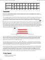
FT-101E/EE/EX
(Mid)
S/N 15,000-20,000
PB1056 PB1314A PB1180B PB1183B PB1315A PB1181B PB1184A PB1076B
PB1192
PB1534
FT-101E/EE/EX
(Late)
S/N 20,001&Up
PB1056 PB1314A PB1180B PB1183C PB1315A PB1181B PB1184A PB1076B
PB1582
PB1534A
FT-101F/FE/FX (All)
PB1056 PB1547 PB1180B PB1183 PB1315B PB1181B PB1184A PB1076B PB1582B PB1534A
S/N All Numbers
The FT-101 is a hybrid radio that employs a solid state transmitter, receiver, and a tube final amplifier. The solid state
features of the radio offer high-performance, low-current characteristics, while the tube amplifier provides a nearly "bulletproof" transmitter and tuner stage.
The tube amplifier consists of a 12BY7A pre-driver stage that feeds a pair of 6JS6C tubes providing a nominal output power
of 130 watts PEP SSB, 90 watts CW, 40 watts AM. The 6JS6C tubes are matched to 50 Ohms through a conventional
pi-output network. The pi-network transforms the 3000 ohm output impedance of the tubes to a 50 Ohm feed system,
provides harmonic attenuation, and can actually match to a variety of output impedances from 25 to 100 Ohms with ease.
The transceivers were made with plug-in boards that could be sent to the factory for replacement or repair. This modular
design was unprecedented in the amateur community, which explains why so many FT-101's are still in use today. In fact,
board extenders could be purchased to extend any board above the main chassis for measurement, alignment, and repair.
For any plug-in board, all voltages, grounds, and signal traces were routed through a single edge connector (facing down into
the main chassis). This removed the need for wires and cables to these circuit boards. This yielded a clean and trim internal
upper chassis. The bulk of the wiring harness is below the deck of the main chassis where all main circuit board edge
connectors are fed. Yes, there are many wires!
FT-101 Block Diagram 54k
FT-101 Top Chassis Photo 106k
FT-101 Bottom Chassis Photo 91k
Please print landscape, margins set to 0.25", 300 or 600 DPI gray scale
The most complicated device in this radio is the Band Selector Switch. This is a 12-position rotary switch that runs from the
front of the radio to the back. It has 13 sections (wafers A thru M) which route everything from DC voltages, oscillator
sections, crystals, tuning circuits, and RF Power in the high-voltage tank and output circuits. One band selector switch
position is used for: 160M, 80M, 40M, 20M, 15M, 10A, 10B, 10C, 10D, 11M or AUX, and WWV receive-only. Each
position allows the main VFO to cover 500kHz on any band.
The entire transceiver was made of metal. Covers, chassis, shields, shafts, etc., are all metal. Even the plastic RF/S-meter
trim and knobs have brass metal inserts. At 35 pounds, there is a lot of metal in this radio! The 10 major circuit boards are
mounted with threaded hardware to the main chassis. Very rugged indeed. A clear plastic sheet covers the entire painted
surface of the faceplate. A well-cared-for FT-101 will still have this clear plastic front.
Because critical circuit designs were kept to a manageable size, hams had no problem in offering circuit changes, isolating
and repairing problems. This knowledge base was so active that in January 1972, Milton Lowens WA2AOQ, founded the
International Fox Tango Club and the Fox Tango Newsletter. The Fox Tango Newsletters were published for 14 years
covering the early FT-101's thru the latest Yaesu Transceivers in 1985. By then, surface mount technology and circuit
complexity outpaced many ham's ability to maintain this level of equipment. In doing so, new chapters in circuit densities,
solid state transmitters, and LSI chips were born, which closed the door (and the covers) to many radios.
Built-in AC and DC power supplies.
True RF Speech Processor.
20/07/2010 12.36