1
SPLIT-TYPE, COOLING AIR CONDITIONERS
No. OC134
REVISED EDITION-A
TECHNICAL & SERVICE MANUAL
Series PC Ceiling Suspended
Indoor unit
[Model names]
PC-2GJA
PC-2.5GJA
PC-3GJA
PC-4GJSA
PC-5GJSA
PC-6GJSA
[Service Ref.]
PC-2GJA1
PC-2.5GJA1
PC-3GJA1
PC-4GJSA1
1998 PC-5GJSA1
PC-6GJSA1
1997
This manual does not cover the
following outdoor units.
When
serving them, please refer to the
service
manual
No.OC127(REVISED EDITION-A) .
[Service Ref.]
PU-2VJA2
PU-2NJA1
PU-2.5VJA2
PU-2.5NJA1
PU-3NJA1
PU-3YJA3
PU-3VJA2
PU-4TJSA2
PU-4VLJSA2
PU-4YJSA3
PU-5YJSA
PU-5TJSA
PU-6YJSA
PU-6TJSA
CONTENTS
INDOOR UNIT
Revision:
●PC-5GJSA1,PC-6GJSA1
are added.
●The first edition has been partially modified.
●Please destroy OC134.
TIMER
TEMP
12
29
11
28
COOL
10
27
DRY
9
26
FAN
8
25
7
24
6
23
5
22
4
21
3
20
2
19
1
18
TIMER/TEMP.
UP
POWER
HIGH
ON/OFF
MODE
SELECT
LOW
FAN
SPEED
ON
LOUVER
1. FEATURES ···········································2
2. PART NAMES AND FUNCTIONS ········4
3. SPECIFICATIONS·································6
4. DATA ·····················································9
5. OUTLINES AND DIMENSIONS··········12
6. WIRING DIAGRAM·····························17
7. REFRIGERANT SYSTEM DIAGRAM ······18
8. OPERATION FLOW-CHART ··············20
9. MICROPROCESSOR CONTROL·······23
10. TROUBLE SHOOTING ·······················29
11. DISASSEMBLY PROCEDURE ···········30
12. PARTS LIST········································35
13. OPTIONAL PARTS ·····························46
DOWN
AUTO
STOP
START
TIMER
MODE
MITSUBISHI ELECTRIC
REMOTE CONTROLLER
The Slim Line.
From Mitsubishi Electric.
1
FEATURES
Series PC Ceiling Suspended
TIMER
TEMP
12
29
11
28
10
27
9
26
8
25
7
24
6
23
5
22
4
21
3
20
2
19
1
18
TIMER/TEMP.
POWER
COOL
DRY
FAN
UP
HIGH
ON/OFF
MODE
SELECT
LOW
FAN
SPEED
ON
LOUVER
DOWN
AUTO
STOP
START
TIMER
MODE
MITSUBISHI ELECTRIC
Indoor unit
Service Ref.
PC-2GJA1
PC-2.5GJA1
PC-3GJA1
PC-4GJSA1
PC-5GJSA1
PC-6GJSA1
Remote controller
Cooling Capacity (50 / 60Hz)
W
Btu/h
5,600/5,400
19,100/18,400
6,500/7,000
22,200/23,900
7,200/7,800
24,600/26,600
9,800/10,800
33,400/36,800
12,400/13,500
42,300/46,100
14,600/15,200
49,800/51,900
Note: Rating condition
Indoor : 27°C D.B., 19°C W.B.
Outdoor : 35°C D.B., 24°C W.B.
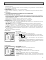
1. ADVANCED REMOTE CONTROLLER
(1) Ultra-thin 12mm (1/2”) remote controller
The streamelined, square controller is designed to blend with any interior. Also, the sophisticated microprocessor allows you to easily carry
TIMER/TEMP.
out a wide range of operations.
POWER
ON/OFF
12
29
(2) Attractive LED display
COOL
11
28
Every operation condition is indicated on the LED display.
MODE
DRY
10
27
SELECT
(3) Simultaneous display of set temperature and room temperature
FAN
9
26
8
25
The set temperature is indicated by continuous light and the room temUP
HIGH
FAN
7
24
SPEED
perature is indicated by a flashing light. In this way, accurate temperaLOW
6
23
DOWN
ture conditions are always available at a glance and fine temperature
5
22
ON
LOUVER
4
21
regulation is possible.
AUTO
3
20
STOP
(4) Convenient 12-hour ON-OFF timer
TIMER
2
19
MODE
START
1
18
The timer switches on and off automatically at the times you set. Once
the timer is set, the remaining time is shown on the LED display.
MITSUBISHI ELECTRIC
(5) Self-diagnostic feature indicates faults instantly
If a problem occurs, the unit will stop operating and the temperature
display will change to a self-diagnosis indicator, which shows the location of the trouble.
(6) Useful memory feature for storing instructions
The previous set value is memorized so that constant temperature control can be achived. For example, if a power failure occurs, the temperature will not have to be readjusted afterwards.
(7) Cables between remote controller and indoor unit
The polar, 12-core type remote controller cables makes installation simple and troublefree. Also, the cables can be
extended up to 50m. (optional)
TIMER
2
TEMP
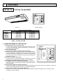
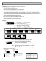
1. AIR OUTLET
New PC series models have 1 air outlet (auto vane switching of horizontal air flow / down flow by switched by auto vane)
instead of 2 (horizontal, and down flows).
2. EASY TO CLEAN ; FLOCKLESS VANE
Protruding portion A
Unifies the air speed
with the vane.
B
+
With our original air current control mechanism, a flockless vane is
Flockless vane
newly adapted.
The flockless vane prevents the condensation on the vane.
A
By changing the vane to the flockless type, the unit can be cleaned
Air outlet
much easier with mild household detergent.
=
Protruding portion B
Sending the air to the upper
area of the vane
Prevents the air comes from
outside the unit
3. NEW MATERIALS FOR BETTER OIL RESISTANCE
We have changed the materials of grill, filer, fan and fan casing from ABS to P.P. (polypropylene) for better oil resistance. As
a result, oil crazing is cut in half.
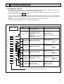
4. SIMPLIFIED INSTALLATION WORK (DIRECT SUSPENDING METHOD)
Simplified the installation work by changing the suspending method to the direct suspending method (suspending the unit
directly from the suspension fixture).
In this way, the unit can be attached to the suspension fixture without removing the installation parts off (Only the side cover
is removed). This method is much simpler than the ¨One-time installation method¨.
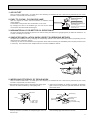
5. IMPROVING EFFICIENCY OF PIPING WORK
New PC series models have 1 air outlet (auto vane switching of horizontal air flow / down flow by switched by auto vane)
instead of 2 (horizontal, and down flows).
1 Removed the knockout work by separating the piping space 2 Improved the flexibility by making it possible for drainage
from the air outlet for efficiency of the piping work.
pipe to exit not only from the right side back but also from
the left side back.
Side panel
Back panel
G
Open
L
U-cut
Drain pan
L
G
D
Open
D
L : Liquid pipe
G: Gas pipe
D: Drain pipe
w Knockout work is needed for the top part. When optional
drain-up machine is installed, the refrigerant pipe exits out
from the top.
Joint coupliy
(attached)
Insulation
cover
Band
(attached)
Rubber plug
Insulation cover
(attached)
Drain pipe
(purchased locally)
w Please move the rubber plug for the unit to the right joint
when drainage pipe exits from the left side.
3
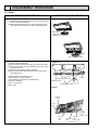
6. QUITENESS ; 43dB : PC-3GJA1(HIGH NOTCH)
Quiteness of the New PC series product is significant. It is because we have adapted the new shape air outlet and changed
the air coures.
Auto vane
Swing
7. EASY MAINTENANCE ; NO MAINTENANCE NECESSARY FOR 2500 HOURS
The new long-life air filter can be used continuously 2500 hours without maintenance (at general office situation).
8. CHOICE OF FILTER
High performance filter can be purchased optionally for the special needs.
Locations
Busy
shops etc···
Regular
office, shops
2
Appropriate filter
High performance
filter
Standard longlife
filter
Capability
Weighing
method 70%
Weighing
method 30%
Filter
2500 hours
2500 hours
Maintenance
The filter can be used
again after cleaning.
The filter can be used
again after cleaning.
How to attach to the unit
Remove the standard long life filter
before attach this optional parts.
It is already attached to
the unit
PART NAMES AND FUNCTION
● Indoor (Main) Unit
Left/right guide vanes
Change the direction of airflow
from the horizontal blower.
Air outlet
Long-life filter
Removes dust and foreigh matter from air coming in
through the grille (Recommended cleaning interval :
Approx, every 2,500 operating hours)
Up/down guide vanes
Change the direction of airflow from the
vartical blower.
4
Air intake
Intake grille
● Remote controller
Settings remain in effect until changed. Air
conditioner can be operated by simply pushing
ON/OFF button once settings have been
made.
Display Panel
Operating panel
ON / OFF button
Pushing button starts
operation. Pushing again
stops operation. Green
lamp remains lit during
operation.
TIMER / TEMP.
This button is used to change
between display of room temperatue and display of remaining timer time durining “AUTO
STOP” operation. Green lamps
light in selected display mode.
Lamps display remaining
timer time or room temperature.
Remaining timer time display
Lamps indicate time remaining
until timer stops timed operation.
Green lamps corresponding to
remaining number of hours light.
MODE SELECT button
TIMER
TEMP
12
29
11
28
COOL
10
27
DRY
9
26
FAN
8
25
7
24
6
23
5
22
4
21
3
20
2
19
1
18
TIMER/TEMP.
UP
POWER
HIGH
ON/OFF
MODE
SELECT
LOW
FAN
SPEED
ON
LOUVER
DOWN
AUTO
STOP
START
TIMER
MODE
Room Temperature display
Lamps display temperatue setings and actual room temperatues.
Temperatue settings.
Green lamps light.
Temperatue in room.
Green lamps flash.
MITSUBISHI ELECTRIC
UP and DOWN buttons
(Example display readings are
for explanations only; actual display readings will differ.)
Temperature control (While ”TEMP” green lamp is
lit.)
Use UP and DOWN buttons to set desired temperature between 18 and 29oC.
Timed operation (While green “TIMER” lamp is lit.)
Use UP and DOWN buttons to set timed operation
between one and twelve hours.
This button is used to
change between cooling.
ventilation and DRY(or heating)operation modes.One of
three green lamps light to
indicate mode in effect.
FAN SPEED button
This button is used to
change between low and
high fan speeds. One of
two green lamps lights to
indicade fan speed in
effect.
Swing Louver Button
Used to automatically
disperse airflow vertically.
Air is blown in one
direction when louver is
not turning. Lamp lights
effect.
TIMER MODE button
Used for selecting timed
starting or stopping.Green
lamp light to indicate
timer mode selected.
Attention:
Pushing UP and DOWN buttons together for more than two seconds will initate “trial run” or “inspection” mode. Avoid
pushing these buttons simultaneously during normal operation. Push ON / OFF button to cancel trial run or inspection
mode if initiated by accident.
All green lamps turn off when air conditioner is stopped.
Avoid operation of buttons with fingernails or other sharp object. Sharp object may scratch operating panel.
*Heating operation mode is only available for models with built-in electric heater.
5
3
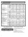
SPECIFICATIONS
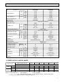
1. STANDARD SPECIFICATIONS
Service Ref.
Item
W
Btu/h
W
Btu/h
W
Btu/h
50Hz
Cooling capacity w1
60Hz
Cooling capacity w4
60Hz
Total input (50/60Hz) w2
Service Ref.
External finish
Fan motor output
50Hz
Outdoor unit
Indoor unit
Airflow Lo-Hi
60Hz
External static pressure
Operation control & Thermostat
50Hz
Noise level Low-High
60Hz
O.D.
Cond. drain connector
W
D
Dimensions
H
Weight
Service Ref.
External finish
Refrigerant (R-22) control
50/60Hz
Crankcase Heater w3
50/60Hz
Compressor output
Protection devices
Fan motor output
50Hz
Airflow
60Hz
50/60Hz
Noise level
W
D
Dimensions
H
Weight
m/min
CFM
m/min
CFM
Pa(mmAq)
dB(A)
dB(A)
mm(in.)
mm(in.)
mm(in.)
mm(in.)
kg(lbs.)
W
kW
kW
K/min(CFM)
K/min(CFM)
dB(A)
mm(in.)
mm(in.)
mm(in.)
kg(lbs.)
PC-2GJA1
Models
50Hz
60Hz
O
O
O
O
O
O
O
PC-2,2.5,3
1ph220V / 1ph220V
1ph220V / 1ph220V
6,500
7,200
9,800
22,200
24,600
33,400
7,000
7,800
10,800
23,900
26,600
36,800
6,200
6,500
9,300
21,200
22,200
31,700
2.58/3.07
3.30/3.60
3.49/4.47
PC-2.5GJA1
PC-3GJA1
PC-4GJSA1
Munsell 0.70Y 8.59/0.97
0.054
0.07
0.07
0.09
10-13
14-18
14-18
20-25
353-459
494-635
494-635
706-883
10-13
14-18
14-18
20-25
353-459
494-635
494-635
706-883
0 (Direct blow)
Remote control & Built-in
37-42
37-43
37-43
40-45
37-42
37-43
37-43
40-45
26 (1)
26 (1)
26 (1)
26 (1)
1000 (39-3/8)
1310 (51-9/16)
1310 (51-9/16)
1310 (51-9/16)
680 (26-3/4)
680 (26-3/4)
680 (26-3/4)
680 (26-3/4)
210 (8-1/4)
210 (8-1/4)
210 (8-1/4)
270 (10-5/8)
27 (60)
34 (75)
34 (75)
37 (82)
PU-2VJA2,PU-2NJA1 PU-2.5VJA2,PU-2.5NJA1 w9 PU-3JA-type w10 PU-4JSA-type
Munsell 5Y 7/1
Capillary tube
32/32/32/38
32/38
2.0/1.5
2.0/1.7
2.7/2.7
2.2/2.2
w5
w5
w7(V)/w6(Y,T)
w5
0.065
0.085
0.065+0.065
0.085
45 (1588)
50 (1765)
95 (3352)
50 (1765)
45 (1588)
50 (1765)
95 (3352)
50 (1765)
49/50
52/53
54/55
52/53
870 (34-1/4)
870 (34-1/4)
870 (34-1/4)
870 (34-1/4)
295+24 (11-5/8 add 1)
650 (25-5/8)
850 (33-7/16)
1258 (49-1/2)
850 (33-7/16)
60 (132)
71 (157)
94 (207)
73 (161)
PC-4,5,6
1ph220V / 3ph380V
1ph220V / 3ph220V
Rating conditions (JISB8616)
w3. The capacity of crankcase heater (W)
6
PC-4GJSA1
PC-3GJA1
5,600
19,100
5,400
18,400
4,300
14,700
2.54/2.60
PC-2GJA1
Notes : w1. Rating condition (JISB8616)
Indoor : 27 C (80 F) D.B., 19 C (66 F) W.B.
Outdoor : 35 C (95 F) D.B., 24 C (75 F) W.B.
Refrigerant piping length (one way) : 5m (16ft)
w2. Total input based indicated voltage (In/Out)
O
PC-2.5GJA1
w4. Rating condition (SSA385, 386)
Indoor : 29 C (84 F) D.B., 19 C (66 F) W.B.
Outdoor : 46 C (115 F) D.B., 24 C (75 F) W.B.
Refrigerant piping lenght (one way ) : 5m (16ft)
O
O
O
O
O
O
O
O
w5. Inner thermostart, HP switch, LP switch
w6. Thermal switch, Reversed-phase protector, HP switch, LP
switch
Thermal relay
w7. Thermal switch, HP switch, LP switch,
Inner thermostat
w8. Thermal switch, HP switch,Inner thermostat
w9. PU-3JA-type···PU-3VJA2, PU-3YJA3, PU-3NJA1,
w10. PU-4JSA-type···PU-4VLJSA2, PU-4YJSA3, PU-4TJSA2
Service Ref.
Item
50Hz
Cooling capacity w1
60Hz
Cooling capacity w4
60Hz
W
Btu/h
W
Btu/h
W
Btu/h
Total input (50/60Hz) w2
Service Ref.
External finish
Fan motor output
Airflow Lo-Hi
Indoor unit
PC-6GJSA1
12,400
42,300
13,500
46,100
11,600
39,600
4.76/5.89
PC-5GJSA1
14,600
49,800
15,200
51,900
13,400
45,700
5.31/6.41
PC-6GJSA1
Munsell 0.70Y 8.59/0.97
50Hz
Outdoor unit
PC-5GJSA1
60Hz
External static pressure
Operation control & Thermostat
50Hz
Noise level Low-High
60Hz
O.D.
Cond. drain connector
W
D
Dimensions
H
Weight
Service Ref.
External finish
Refrigerant (R-22) control
50/60Hz
Crankcase Heater w3
50/60Hz
Compressor output
Protection devices
Fan motor output
50Hz
Airflow
60Hz
50/60Hz
Noise level
W
D
Dimensions
H
Weight
0.15
27-34
953-1,200
27-34
953-1,200
K/min
CFM
K/min
CFM
Pa(mmAq)
dB(A)
dB(A)
mm(in.)
mm(in.)
mm(in.)
mm(in.)
kg(lbs.)
W
kW
kW
K/min(CFM)
K/min(CFM)
dB(A)
mm(in.)
mm(in.)
mm(in.)
kg(lbs.)
0.15
27-34
953-1,200
27-34
953-1,200
0 (Direct blow)
Remote control & Built-in
41-46
42-48
41-46
42-48
26(1)
26(1)
1,620(63-3/4)
1,620(63-3/4)
680(26-3/4)
680(26-3/4)
270(10-5/8)
270(10-5/8)
43(95)
45(99)
PU-5YJSA,PU-5TJSA
PU-6YJSA,PU-6TJSA
Munsell 5Y 7/1
Capillary tube
—
—
3.5
4.2/4.0
w8
w8
0.10+0.10
0.10+0.10
100(3530)
100(3530)
100(3530)
100(3530)
55
56
970(38-3/16)
970(38-3/16)
345+24(13-9/16+1)
345+24(13-9/16+1)
1,258(49-1/2)
1,258(49-1/2)
114
117
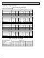
2. POWER SUPPLY & MODEL NAMES
Power supply
50Hz
60Hz
1ph.
Indoor unit Service Ref.
PC-2GJA1
PC-2.5GJA1
PC-3GJA1
PC-4GJSA1 PC-5GJSA1
PC-6GJSA1
Outdoor unit Service Ref.
220,230,240V
PU-2VJA2
PU-2.5VJA2
PU-3VJA2
PU-4VLJSA2
—
—
—
—
PU-3YJA3
PU-4YJSA3
PU-5YJSA
PU-6YJSA
3ph.
380/220, 400/230, 415/240V
1ph.
220V
PU-2NJA1
PU-2.5NJA1
PU-3NJA1
—
—
—
3ph.
220V
—
—
—
PU-4TJSA2
PU-5TJSA
PU-6TJSA
Notes : 1. Power supply key N
: 1ph, 220V/60Hz
T : 3ph, 220V/60Hz
V(L) : 1ph, 220, 230, 240V/50Hz Y : 3ph, 380/220, 400/230, 415/240V, 50Hz, 4wires
2. Primary power supplies for all indoor units are single-phase.
7
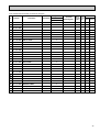
3. ELECTRICAL SPECIFICATIONS
Rating conditions — JIS B8616 Indoor : 27°C (80°F) D.B., 19°C (66°F) W.B.
Outdoor : 35°C (95°F) D.B., 24°C(75°F) W.B.
Serises PC Indoor unit (Single phase)
Power supply (1 Phase)
V : 220V , 50Hz
Service Ref.
Current
Input
Starting current
PC-2GJA1 PC-2.5GJA1 PC-3GJA1 PC-4GJSA1 PC-5GJSA1 PC-6GJSA1
A
0.38
0.51
0.51
0.68
0.96
0.96
kW
0.10
0.12
0.12
0.14
0.20
0.20
A
1.10
1.17
1.17
1.36
2.00
2.00
PU-2
PU-2.5
PU-3
PU-4
PU-5
PU-6
Outdoor unit to be connected
Power supply (1 Phase)
V : 230V , 50Hz
Service Ref.
Current
Input
Starting current
PC-2GJA1 PC-2.5GJA1 PC-3GJA1 PC-4GJSA1 PC-5GJSA1 PC-6GJSA1
A
0.41
0.53
0.53
0.69
1.01
1.01
kW
0.12
0.13
0.13
0.15
0.22
0.22
A
1.15
1.22
1.22
1.42
2.10
2.10
PU-2
PU-2.5
PU-3
PU-4
PU-5
PU-6
Outdoor unit to be connected
Power supply (1 Phase)
V : 240V , 50Hz
Service Ref.
Current
Input
Starting current
PC-2GJA1 PC-2.5GJA1 PC-3GJA1 PC-4GJSA1 PC-5GJSA1 PC-6GJSA1
A
0.43
0.55
0.55
0.70
1.06
1.06
kW
0.14
0.15
0.15
0.16
0.25
0.25
A
1.20
1.27
1.27
1.48
2.20
2.20
PU-2
PU-2.5
PU-3
PU-4
PU-5
PU-6
Outdoor unit to be connected
Power supply (1 Phase)
N : 220V , 60Hz
Service Ref.
Current
Input
Starting current
PC-2GJA1 PC-2.5GJA1 PC-3GJA1 PC-4GJSA1 PC-5GJSA1 PC-6GJSA1
A
0.61
0.70
0.70
0.95
1.20
1.20
kW
0.15
0.16
0.16
0.20
0.26
0.26
A
Outdoor unit to be connected
1.03
1.11
1.11
1.27
1.91
1.91
PU-2
PU-2.5
PU-3
PU-4
PU-5
PU-6
Rating conditions — SSA385, 386
Indoor : 29°C (84°F) D.B., 19°C (66°F) W.B.
Outdoor : 46°C (115°F) D.B., 24°C(75°F) W.B.
Power supply (1 Phase)
N : 220V , 60Hz
Service Ref.
Current
Input
Starting current
PC-2GJA1 PC-2.5GJA1 PC-3GJA1 PC-4GJSA1 PC-5GJSA1 PC-6GJSA1
A
0.61
0.70
0.70
0.95
1.20
1.20
kW
0.15
0.16
0.16
0.20
0.26
0.26
A
1.03
1.11
1.11
1.27
1.91
1.91
PU-2
PU-2.5
PU-3
PU-4
PU-5
PU-6
Outdoor unit to be connected
8
4
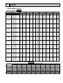
DATA
1. PERFORMANCE DATA
Cooling capacity 50Hz
Service Ref.
Temperature
Outdoor D.B.
Indoor W.B.
16°C (60.8°F)
18°C (64.4°F)
21°C
19°C (66.2°F)
(69.8°F)
19.4°C (67°F)
20°C (68°F)
22°C (71.6°F)
16°C (60.8°F)
18°C (64.4°F)
25°C
19°C (66.2°F)
(77°F)
19.4°C (67°F)
20°C (68°F)
22°C (71.6°F)
16°C (60.8°F)
18°C (64.4°F)
30°C
19°C (66.2°F)
(86°F)
19.4°C (67°F)
20°C (68°F)
22°C (71.6°F)
16°C (60.8°F)
18°C (64.4°F)
32.2°C
19°C (66.2°F)
(90°F)
19.4°C (67°F)
20°C (68°F)
22°C (71.6°F)
16°C (60.8°F)
18°C (64.4°F)
35°C
19°C (66.2°F)
(95°F)
19.4°C (67°F)
20°C (68°F)
22°C (71.6°F)
16°C (60.8°F)
18°C (64.4°F)
40°C
19°C (66.2°F)
(104°F)
19.4°C (67°F)
20°C (68°F)
22°C (71.6°F)
16°C (60.8°F)
18°C (64.4°F)
40.6°C
19°C (66.2°F)
(105°F)
19.4°C (67°F)
20°C (68°F)
22°C (71.6°F)
16°C (60.8°F)
18°C (64.4°F)
45°C
19°C (66.2°F)
(113°F)
19.4°C (67°F)
20°C (68°F)
22°C (71.6°F)
16°C (60.8°F)
18°C (64.4°F)
46°C
19°C (66.2°F)
(115°F)
19.4°C (67°F)
20°C (68°F)
22°C (71.6°F)
16°C (60.8°F)
18°C (64.4°F)
50°C
19°C (66.2°F)
(69.8°F)
19.4°C (67°F)
20°C (68°F)
22°C (71.6°F)
16°C (60.8°F)
18°C (64.4°F)
52°C
19°C (66.2°F)
(125.5°F)
19.4°C (67°F)
20°C (68°F)
22°C (71.6°F)
PC-2GJA1
C.F.
T.C.
(T.I.)
0.81
5.6
0.82
6.0
0.83
6.2
0.83
6.2
0.84
6.4
0.86
6.7
0.84
5.5
0.85
5.9
0.86
6.0
0.86
6.1
0.87
6.2
0.89
6.6
0.90
5.3
0.92
5.6
0.93
5.8
0.93
5.9
0.94
6.0
0.96
6.4
0.93
5.2
0.95
5.5
0.96
5.7
0.97
5.8
0.97
5.9
0.99
6.3
0.96
5.1
0.99
5.4
1.00
5.6
1.00
5.7
1.01
5.8
1.04
6.2
1.03
4.9
1.06
5.2
1.07
5.4
1.08
5.4
1.08
5.5
1.11
5.9
1.04
4.8
1.06
5.2
1.08
5.3
1.08
5.4
1.09
5.5
1.12
5.9
1.10
4.6
1.12
4.9
1.14
5.1
1.15
5.2
1.16
5.3
1.20
5.7
1.11
4.6
1.14
4.9
1.15
5.1
1.16
5.1
1.17
5.2
1.21
5.6
1.16
4.4
1.19
4.7
1.21
4.9
1.22
4.9
1.23
5.0
1.28
5.4
1.19
4.3
1.22
4.6
1.24
4.7
1.25
4.8
1.26
4.9
1.31
5.3
PC-2.5GJA1
T.C.
C.F.
(T.I.)
6.5
0.81
6.9
0.82
7.2
0.83
7.3
0.83
7.4
0.84
7.8
0.86
6.4
0.84
6.8
0.85
7.0
0.86
7.1
0.86
7.2
0.87
7.7
0.89
6.1
0.90
6.6
0.92
6.8
0.93
6.9
0.93
7.0
0.94
7.4
0.96
6.0
0.93
6.4
0.95
6.6
0.96
6.7
0.97
6.9
0.97
7.3
0.99
5.9
0.96
6.3
0.99
6.5
1.00
6.6
1.00
6.7
1.01
7.2
1.04
5.6
1.03
6.0
1.06
6.2
1.07
6.3
1.08
6.4
1.08
6.9
1.11
5.6
1.04
6.0
1.06
6.2
1.08
6.3
1.08
6.4
1.09
6.8
1.12
5.4
1.10
5.7
1.12
5.9
1.14
6.0
1.15
6.1
1.16
6.6
1.20
5.3
1.11
5.7
1.14
5.9
1.15
6.0
1.16
6.1
1.17
6.5
1.21
5.1
1.16
5.4
1.19
5.6
1.21
5.7
1.22
5.8
1.23
6.3
1.28
4.9
1.19
5.3
1.22
5.5
1.24
5.6
1.25
5.7
1.26
6.1
1.31
PC-3GJA1
C.F.
T.C.
(T.I.)
0.81
7.2
0.82
7.7
0.83
7.9
0.83
8.0
0.84
8.2
0.86
8.7
0.84
7.1
0.85
7.5
0.86
7.8
0.86
7.9
0.87
8.0
0.89
8.5
0.90
6.8
0.92
7.3
0.93
7.5
0.93
7.6
0.94
7.7
0.96
8.2
0.93
6.7
0.95
7.1
0.96
7.4
0.97
7.5
0.97
7.6
0.99
8.1
0.96
6.5
0.99
7.0
1.00
7.2
1.00
7.3
1.01
7.4
1.04
7.9
1.03
6.2
1.06
6.7
1.07
6.9
1.08
7.0
1.08
7.1
1.11
7.6
1.04
6.2
1.06
6.6
1.08
6.9
1.08
6.9
1.09
7.1
1.12
7.6
1.10
5.9
1.12
6.4
1.14
6.6
1.15
6.7
1.16
6.8
1.20
7.3
1.11
5.9
1.14
6.3
1.15
6.5
1.16
6.6
1.17
6.7
1.21
7.2
1.16
5.6
1.19
6.0
1.21
6.2
1.22
6.3
1.23
6.5
1.28
6.9
1.19
5.5
1.22
5.9
1.24
6.1
1.25
6.2
1.26
6.3
1.31
6.8
PC-4GJSA1
C.F.
T.C.
(T.I.)
0.81
9.8
0.82
10.5
0.83
10.8
0.83
10.9
0.84
11.1
0.86
11.8
0.84
9.6
0.85
10.2
0.86
10.6
0.86
10.7
0.87
10.9
0.89
11.6
0.90
9.3
0.92
9.9
0.93
10.2
0.93
10.3
0.94
10.5
0.96
11.2
0.93
9.1
0.95
9.7
0.96
10.0
0.97
10.2
0.97
10.3
0.99
11.0
0.96
8.9
0.99
9.5
1.00
9.8
1.00
9.9
1.01
10.1
1.04
10.8
1.03
8.5
1.06
9.1
1.07
9.4
1.08
9.5
1.08
9.7
1.11
10.3
1.04
8.4
1.06
9.0
1.08
9.3
1.08
9.5
1.09
9.6
1.12
10.3
1.10
8.1
1.12
8.6
1.14
8.9
1.15
9.1
1.16
9.3
1.20
9.9
1.11
8.0
1.14
8.6
1.15
8.9
1.16
9.0
1.17
9.2
1.21
9.8
1.16
7.6
1.19
8.2
1.21
8.5
1.22
8.6
1.23
8.8
1.28
9.4
1.19
7.4
1.22
8.0
1.24
8.3
1.25
8.4
1.26
8.6
1.31
9.2
PC-5GJSA1
T.C.
C.F.
(T.I.)
12.4
0.81
13.3
0.82
13.7
0.83
13.8
0.83
14.1
0.84
14.9
0.86
12.2
0.84
13.0
0.85
13.4
0.86
13.6
0.86
13.8
0.87
14.7
0.89
11.7
0.90
12.5
0.92
12.9
0.93
13.1
0.93
13.3
0.94
14.2
0.96
11.5
0.93
12.3
0.95
12.7
0.96
12.8
0.97
13.1
0.97
13.9
0.99
11.2
0.96
12.0
0.99
12.4
1.00
12.6
1.00
12.8
1.01
13.6
1.04
10.7
1.03
11.5
1.06
11.9
1.07
12.0
1.08
12.3
1.08
13.1
1.11
10.7
1.04
11.4
1.06
11.8
1.08
12.0
1.08
12.2
1.09
13.0
1.12
10.2
1.10
10.9
1.12
11.3
1.14
11.5
1.15
11.7
1.16
12.5
1.20
10.1
1.11
10.8
1.14
11.2
1.15
11.3
1.16
11.5
1.17
12.4
1.21
9.1
1.16
9.8
1.19
10.2
1.21
10.3
1.22
10.5
1.23
10.9
1.28
8.1
1.19
8.7
1.22
9.0
1.24
9.1
1.25
9.3
1.26
9.7
1.31
PC-6GJSA1
T.C.
C.F.
(T.I.)
14.7
0.81
15.6
0.82
16.1
0.83
16.3
0.83
16.6
0.84
17.6
0.86
14.3
0.84
15.3
0.85
15.8
0.86
16.0
0.86
16.3
0.87
17.3
0.89
13.8
0.90
14.7
0.92
15.2
0.93
15.4
0.93
15.7
0.94
16.7
0.96
13.6
0.93
14.5
0.95
14.9
0.96
15.1
0.97
15.4
0.97
16.4
0.99
13.2
0.96
14.1
0.99
14.6
1.00
14.8
1.00
15.1
1.01
16.1
1.04
12.6
1.03
13.5
1.06
14.0
1.07
14.2
1.08
14.4
1.08
15.4
1.11
12.6
1.04
13.4
1.06
13.9
1.08
14.1
1.08
14.4
1.09
15.3
1.12
12.0
1.10
12.9
1.12
13.3
1.14
13.5
1.15
13.8
1.16
14.7
1.20
11.9
1.11
12.7
1.14
13.1
1.15
13.3
1.16
13.5
1.17
14.6
1.21
10.7
1.16
11.5
1.19
12.0
1.21
12.1
1.22
12.4
1.23
12.8
1.28
9.5
1.19
10.2
1.22
10.6
1.24
10.7
1.25
11.0
1.26
11.4
1.31
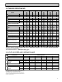
Cooling Capacity Correction Factors 50Hz
Service Ref.
PC-2GJA1
PC-2.5GJA1
PC-3GJA1
PC-4GJSA1
PC-5GJSA1
PC-6GJSA1
5m(16ft)
1.0
1.0
1.0
1.0
1.0
1.0
Refrigerant piping length (one way)
10m(33ft) 15m(49ft) 20m(66ft) 25m(82ft) 30m(98ft) 35m(115ft) 40m(131ft) 45m(148ft) 50m(164ft)
—
—
—
—
0.985
0.975
0.964
0.954
0.944
—
—
—
—
0.983
0.972
0.961
0.951
0.940
—
—
—
—
0.978
0.962
0.948
0.934
0.921
—
0.935
0.926
—
0.984
0.974
0.964
0.954
0.944
0.962
0.908
0.896
0.884
0.875
0.948
0.934
0.921
0.978
0.880
0.864
0.850
0.840
0.950
0.931
0.912
0.896
0.970
9
Cooling capacity
60Hz
PC-3GJA1
PC-4GJSA1
PC-2GJA1
PC-2.5GJA1
PC-5GJSA1
Service Ref.
T.C.
C.F.
C.F.
C.F.
C.F.
T.C.
T.C.
T.C.
C.F.
T.C.
Temperature
(T.I.)
(T.I.)
(T.I.)
(T.I.)
(T.I.)
Outdoor D.B.
Indoor W.B.
13.6
0.81
0.81
0.81
0.81
7.0
7.8
10.8
0.81
5.4
16°C (60.8°F)
14.4
0.82
0.82
0.82
0.82
7.5
8.3
11.5
0.82
5.8
18°C (64.4°F)
21°C
14.9
0.83
0.83
0.83
0.83
7.7
8.6
11.9
0.83
6.0
19°C (66.2°F)
(69.8°F)
15.1
0.83
0.83
0.83
0.83
7.8
8.7
12.0
0.83
6.0
19.4°C (67°F)
(68°F)
15.3
0.84
0.84
0.84
0.84
7.9
8.9
12.3
0.84
6.1
20°C
(
)
16.2
0.86
0.86
0.86
0.86
8.4
9.4
13.0
0.86
6.5
22°C
71.6°F
16°C (60.8°F)
13.2
0.84
0.84
0.84
0.84
6.9
7.7
10.6
5.3
0.84
18°C (64.4°F)
14.1
0.85
0.85
0.85
0.85
7.3
8.2
11.3
5.6
0.85
25°C
19°C (66.2°F)
14.6
0.86
0.86
0.86
0.86
7.6
8.4
11.7
5.8
0.86
(77°F)
19.4°C (67°F)
14.8
0.86
0.86
0.86
0.86
7.7
8.5
11.8
5.9
0.86
(68°F)
20°C
15.0
0.87
0.87
0.87
0.87
7.8
8.7
12.0
6.0
0.87
22°C (71.6°F)
16.0
0.89
0.89
0.89
0.89
8.3
9.2
12.8
6.4
0.89
12.8
0.90
0.90
0.90
0.90
6.6
7.4
10.2
0.90
5.1
16°C (60.8°F)
13.6
0.92
0.92
0.92
0.92
7.1
7.9
10.9
0.92
5.4
18°C (64.4°F)
30°C
(
)
14.0
0.93
0.93
0.93
0.93
7.3
8.1
11.2
0.93
5.6
19°C
66.2°F
(86°F)
14.2
0.93
0.93
0.93
0.93
7.4
8.2
11.4
0.93
5.7
19.4°C (67°F)
(68°F)
14.5
0.94
0.94
0.94
0.94
7.5
8.4
11.6
0.94
5.8
20°C
15.4
0.96
0.96
0.96
0.96
8.0
8.9
12.3
0.96
6.2
22°C (71.6°F)
16°C (60.8°F)
12.5
0.93
0.93
0.93
0.93
6.5
7.2
10.0
0.93
5.0
18°C (64.4°F)
13.4
0.95
0.95
0.95
0.95
6.9
7.7
10.7
0.95
5.3
32.2°C
19°C (66.2°F)
13.8
0.96
0.96
0.96
0.96
7.2
8.0
11.0
0.96
5.5
(90°F)
19.4°C (67°F)
14.0
0.97
0.97
0.97
0.97
7.3
8.1
11.2
0.97
5.6
(68°F)
20°C
14.3
0.97
0.97
0.97
0.97
7.4
8.2
11.4
0.97
5.7
22°C (71.6°F)
15.2
0.99
0.99
0.99
0.99
7.9
8.8
12.1
0.99
6.1
16°C (60.8°F)
12.2
0.96
0.96
0.96
0.96
6.3
7.1
9.8
4.9
0.96
18°C (64.4°F)
13.1
0.99
0.99
0.99
0.99
6.8
7.5
10.5
5.2
0.99
35°C
19°C (66.2°F)
13.5
1.00
1.00
1.00
1.00
7.0
7.8
10.8
5.4
1.00
(95°F)
(
)
19.4°C
67°F
13.7
1.00
1.00
1.00
1.00
7.1
7.9
10.9
5.5
1.00
(68°F)
20°C
13.9
1.01
1.01
1.01
1.01
7.2
8.1
11.1
5.6
1.01
22°C (71.6°F)
14.9
1.04
1.04
1.04
1.04
7.7
8.6
11.9
5.9
1.04
11.7
1.03
1.03
1.03
1.03
6.1
6.8
9.4
1.03
4.7
16°C (60.8°F)
12.5
1.06
1.06
1.06
1.06
6.5
7.2
10.0
1.06
5.0
18°C (64.4°F)
40°C
12.9
1.07
1.07
1.07
1.07
6.7
7.5
10.3
1.07
5.2
19°C (66.2°F)
(104°F)
13.1
1.08
1.08
1.08
1.08
6.8
7.6
10.5
1.08
5.2
19.4°C (67°F)
(68°F)
13.4
1.08
1.08
1.08
1.08
6.9
7.7
10.7
1.08
5.3
20°C
14.3
1.11
1.11
1.11
1.11
7.4
8.2
11.4
1.11
5.7
22°C (71.6°F)
(
)
16°C
60.8°F
11.6
1.04
1.04
1.04
1.04
6.0
6.7
9.3
1.04
4.7
18°C (64.4°F)
12.4
1.06
1.06
1.06
1.06
6.4
7.2
9.9
1.06
5.0
40.6°C
19°C (66.2°F)
12.9
1.08
1.08
1.08
1.08
6.7
7.4
10.3
1.08
5.1
(105°F)
19.4°C (67°F)
13.0
1.08
1.08
1.08
1.08
6.8
7.5
10.4
1.08
5.2
(
)
20°C
68°F
13.3
1.09
1.09
1.09
1.09
6.9
7.7
10.6
1.09
5.3
22°C (71.6°F)
14.2
1.12
1.12
1.12
1.12
7.4
8.2
11.3
1.12
5.7
16°C (60.8°F)
11.1
1.10
1.10
1.10
1.10
5.8
6.4
8.9
1.10
4.4
18°C (64.4°F)
11.9
1.12
1.12
1.12
1.12
6.2
6.9
9.5
1.12
4.8
45°C
19°C (66.2°F)
12.3
1.14
1.14
1.14
1.14
6.4
7.1
9.9
1.14
4.9
(113°F)
19.4°C (67°F)
12.5
1.15
1.15
1.15
1.15
6.5
7.2
10.0
1.15
5.0
(68°F)
20°C
12.7
1.16
1.16
1.16
1.16
6.6
7.4
10.2
1.16
5.1
22°C (71.6°F)
13.6
1.20
1.20
1.20
1.20
7.1
7.9
10.9
1.20
5.5
11.0
1.11
1.11
1.11
1.11
5.7
6.4
8.8
1.11
4.4
16°C (60.8°F)
(
)
11.8
1.14
1.14
1.14
1.14
6.1
6.8
9.4
1.14
4.7
18°C
64.4°F
46°C
12.1
1.15
1.15
1.15
1.15
6.3
7.1
9.8
1.15
4.9
19°C (66.2°F)
(115°F)
12.3
1.16
1.16
1.16
1.16
6.4
7.1
9.9
1.16
4.9
19.4°C (67°F)
(68°F)
12.5
1.17
1.17
1.17
1.17
6.5
7.3
10.1
1.17
5.0
20°C
(
)
13.5
1.21
1.21
1.21
1.21
7.0
7.8
10.8
1.21
5.4
22°C
71.6°F
16°C (60.8°F)
9.9
1.16
1.16
1.16
1.16
5.5
6.1
8.4
1.16
4.2
18°C (64.4°F)
10.7
1.19
1.19
1.19
1.19
5.9
6.5
9.0
1.19
4.5
50°C
19°C (66.2°F)
11.1
1.21
1.21
1.21
1.21
6.1
6.8
9.4
1.21
4.7
(69.8°F)
19.4°C (67°F)
11.2
1.22
1.22
1.22
1.22
6.2
6.9
9.5
1.22
4.7
(68°F)
20°C
11.4
1.23
1.23
1.23
1.23
6.3
7.0
9.7
1.23
4.8
22°C (71.6°F)
11.8
1.28
1.28
1.28
1.28
6.7
7.5
10.4
1.28
5.2
16°C (60.8°F)
8.8
1.19
1.19
1.19
1.19
5.3
5.9
8.2
1.19
4.1
18°C (64.4°F)
9.4
1.22
1.22
1.22
1.22
5.7
6.4
8.8
1.22
4.4
52°C
(
)
19°C
66.2°F
9.8
1.24
1.24
1.24
1.24
5.9
6.6
9.2
1.24
4.6
(125.5°F)
19.4°C (67°F)
9.9
1.25
1.25
1.25
1.25
6.0
6.7
9.3
1.25
4.6
(68°F)
20°C
10.1
1.26
1.26
1.26
1.26
6.1
6.9
9.5
1.26
4.7
22°C (71.6°F)
10.5
1.31
1.31
1.31
1.31
6.6
7.3
10.2
1.31
5.1
Notes:1.T.C. : Total capacity (x kW)...Btu/h=(W)x0.86
C.F. (T.I.) : Correction factors of Total input + Outdoor unit input)
2.(oF)=32+9/5(oC)
Lower limit...Indoor 21oC(70oF) D.B.,15.5oC(60oF) W.B., Outodoor 21oC(70oF) D.B.
3.Guaranteed operating range (cooling):
Upper limit...Indoor 35oC(95oF) D.B.,22.5oC(72.5oF) W.B.,Outodoor 52oC(125.5oF) D.B.
{
Cooling Capacity Correction Factors
Service Ref.
PC-2GJA1
PC-2.5GJA1
PC-3GJA1
PC-4GJSA1
PC-5GJSA1
PC-6GJSA1
10
5m(16ft)
1.0
1.0
1.0
1.0
1.0
1.0
PC-6GJSA1
T.C.
C.F.
(T.I.)
15.3
0.81
16.2
0.82
16.8
0.83
17.0
0.83
17.3
0.84
18.3
0.86
14.9
0.84
15.9
0.85
16.4
0.86
16.6
0.86
16.9
0.87
18.0
0.89
14.4
0.90
15.3
0.92
15.8
0.93
16.0
0.93
16.3
0.94
17.4
0.96
14.1
0.93
15.1
0.95
15.5
0.96
15.7
0.97
16.0
0.97
17.1
0.99
13.8
0.96
14.7
0.99
15.2
1.00
15.4
1.00
15.7
1.01
16.7
1.04
13.2
1.03
14.1
1.06
14.6
1.07
14.7
1.08
15.0
1.08
16.0
1.11
13.1
1.04
14.0
1.06
14.5
1.08
14.7
1.08
15.0
1.09
16.0
1.12
12.5
1.10
13.4
1.12
13.9
1.14
14.1
1.15
14.4
1.16
15.3
1.20
12.4
1.11
13.3
1.14
13.7
1.15
13.8
1.16
14.1
1.17
15.2
1.21
11.2
1.16
12.0
1.19
12.4
1.21
12.6
1.22
12.9
1.23
13.3
1.28
9.9
1.19
10.6
1.22
11.0
1.24
11.2
1.25
11.4
1.26
11.8
1.31
}
60Hz
Refrigerant piping length (one way)
10m(33ft) 15m(49ft) 20m(66ft) 25m(82ft) 30m(98ft) 35m(115ft) 40m(131ft) 45m(148ft) 50m(164ft)
0.985
0.975
0.964
0.954
0.944
—
—
—
—
0.978
0.963
0.948
0.934
0.921
—
—
—
—
0.971
0.950
0.931
0.913
0.896
—
—
—
—
0.980
0.966
0.952
0.939
0.826
0.914
0.902
—
—
0.971
0.950
0.931
0.913
0.896
0.880
0.864
0.850
0.840
0.960
0.933
0.908
0.885
0.864
0.845
0.828
0.812
0.800
2. STANDARD OPERATION DATA
Service Ref.
PC-2GJA1
Total
Electrical circuit
PC-6GJSA1
W
5,600 4,300 6,500 6,200 7,200 6,500 9,800 9,300 12,400 11,600 14,600 13,400
Input
kW
2.54
3.12
2.58
3.60
3.30
Indoor unit Service Ref.
PC-2GJA1
PC-2.5GJA1
phase, Hz
1,50
1,60
1,50
1,60
1,50
4.25
PC-3GJA1
3.43
5.17
4.76
6.94
5.31
7.54
PC-4GJSA1
PC-5GJSA1 PC-6GJSA1
1,60
1,50
1,60
1,50
1,60
1,50
1,60
Volts
V
220
220
220
220
220
220
220
220
220
220
220
220
Amperes
A
0.38
0.61
0.51
0.70
0.51
0.70
0.68
0.95
0.96
1.20
0.96
1.20
PUPU- PUPU- PUPU- PU- PU- PU- PU- PU- PU2VJA2 2NJA1 2.5VJA2 2.5NJA1 3VJA2 3NJA1 4YJSA3 4TJSA2 5YJSA 5TJSA 6YJSA 6TJSA
Outdoor unit Service Ref.
phase, Hz
Amperes
Refrigerant circuit
PC-4GJSA1 PC-5GJSA1
Capacity
Volts
Indoor side
PC-3GJA1
Cooling Cooling Cooling Cooling Cooling Cooling Cooling Cooling Cooling Cooling Cooling Cooling
MODE
Outdoor
side
PC-2.5GJA1
1,50
1,60
1,50
1,60
1,50
1,60
3,50
3,60
3,50
3,60
3,50
3,60
V
220
220
220
220
220
220
380
220
380
220
380
220
A
11.3
13.6
11.4
15.8
15.1
20.9
5.7
14.0
8.15 19.61 8.63 21.45
MPa.G
(kgf/F•G)
MPa.G
(kgf/F•G)
1.93
(19.7)
0.44
(4.5)
2.49
(25.4)
0.53
(5.4)
1.96
(20.0)
0.5
(5.1)
2.68
(27.3)
0.52
(5.3)
1.96
(20.0)
0.44
(4.5)
2.54
(25.9)
0.44
(4.5)
1.80
(18.3)
0.51
(5.2)
2.40
(24.4)
0.51
(5.2)
1.83
(18.7)
0.46
(4.7)
2.41
(24.6)
0.43
(4.4)
1.96
(20.0)
0.41
(4.2)
2.41
(24.6)
0.42
(4.3)
Discharge temperature
°C
68.6
77.7
72.3
94.3
63.9
82.0
67.5
88.4
72.9
94.8
75.4
94.8
Condensing temperature
°C
51.6
60.5
52.4
57.6
52.3
61.6
48.3
54.5
48.8
60.1
51.1
60.3
Suction temperature
°C
3.3
8.3
8.6
10.2
3.7
3.6
7.3
6.0
3.1
1.7
2.3
1.6
Ref. pipe length
m
5
5
5
5
5
5
5
5
5
5
5
5
D.B.°C
27
29
27
29
27
29
27
29
27
29
27
29
W.B.°C
19
19
19
19
19
19
19
19
19
19
19
19
D.B.°C
9.7
13.8
12.0
15.3
10.7
12.8
10.5
11.7
13.7
14.9
12.2
12.6
D.B.°C
35
46
35
46
35
46
35
46
35
46
35
46
W.B.°C
24
24
24
24
24
24
24
24
24
24
24
24
Discharge pressure
Suction pressure
Intake air temperature
Discharge air temperature
Intake air temperature
The unit of pressure has been changed to MPa based on SI(International System of unit) in accordance with I.S.O.(International
Organization for Standardization).
The conversion factor is : 1(MPa•G)=10.2(kgf / F•G)
60Hz
50Hz
Frequency
3. OUTLET AIR SPEED AND COVERAGE RANGE
Configuration
Ceiling suspended
Service Ref.
PC-2GJA1
PC-2.5GJA1
PC-3GJA1
PC-4GJSA1
3
PC-5GJSA1 PC-6GJSA1
Airflow
m /min
13
18
18
25
34
34
Air speed
m/sec.
3.7
3.8
3.8
4.1
4.38
4.38
Coverage
m
8.8
10.4
10.4
12.6
15.2
15.2
range
ft
29
34.5
34.5
41.6
50.0
50.0
Airflow
m /min
13
18
18
25
34
34
Air speed
m/sec.
3.7
3.8
3.8
4.1
4.38
4.38
Coverage
m
8.8
10.4
10.4
12.6
15.2
15.2
range
ft
29
34.5
34.5
41.6
50.0
50.0
3
The air coverage range is the value up to the position
where the air speed is 0.25 m/sec. when air is blown out
horizontally from the unit at Hi notch position.
The coverage range should be used as a general guideline since it varies according to the size of the room and
furniture inside the room.
11
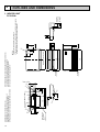
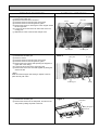
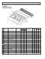
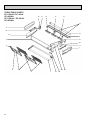
When electrical
box is pulled
down
6-7
928
1
Electrical box 70
525
Celling
8
Electrical box [FRONT VIEW]
32
161
3
2
226
86
2
138
171
263
352
5
1 4
Gap to ceiling
Air intake
Air outlet
918
1000
904
983
933 (suspension bolt pitch)
140
6
70
15
85
(3/8F) liquid
(5/8F) gas
(Drainage)
182
201
241
NOTES:
1. Use M10 or W3/8 screws for anchor bolt.
2. Please be sure when installing the drain-up machine (option parts).
refrigerant pipe will be only upper drain pipe arrangement.
5 Refrigerant-pipe connection (liquid pipe side/flared connection)
6 Knock out hole for upper drain pipe arrangement
7 Knock out hole for left drain pipe arrangement
8 Knock out hole for wiring arrangement
131
17
150
Drainage pipe connection (26mm I.D.)
Drainage pipe connection (for the left arrangement)
Knock out hole for left drain-piping arrangement
Refrigerant-pipe connection (gas pipe side/flared connection)
179
42
3879
38
1
46 175
80
320
180
210
1
2
3
4
81 76
254
1. INDOOR UNIT
PC-2GJA1
680
12
157
5
OUTLINES AND DIMENSIONS
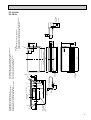
When electrical
box is pulled
down
2
1235
1
Electrical box
525
Celling
70
8
[ FRONT VIEW ]
226
2
86
138
171
263
416
5
1 4
Air outlet
Gap to ceiling
Air intake
131
Electrical box
32
161
3
179
42
3879
38
1
46 175
17
6~7
150
1228
1310
1214
1290
1240 (suspension bolt pitch)
140
70
6
210
80
15
85
(3/8F liquid)
(5/8F gas)
(Drainage)
182
201
241
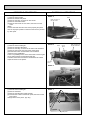
NOTES:
1. Use M10 or W3/8 screws for anchor bolt.
2. Please be sure when installing the drain-up machine (option parts).
refrigerant pipe will be only upper drain pipe arrangement.
5 Refrigerant-pipe connection (liquid pipe side/flared connection)
6 Knock out hole for upper drain pipe arrangement
7 Knock out hole for left drain pipe arrangement
8 Knock out hole for wiring arrangement
81 76
254
320
180
680
Drainage pipe connection (26mm I.D.)
Drainage pipe connection (for the left arrangement)
Knock out hole for left drain-piping arrangement
Refrigerant-pipe connection (gas pipe side/flared connection)
157
1
2
3
4
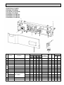
PC-2.5GJA1
PC-3GJA1
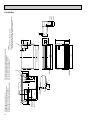
13
3
239
2
When electrical
box is pulled
down
42
93
1
Electrical box
525
160
70
229
1235
Celling
8
[ FRONT VIEW ]
38 140
2
687
38
86
138
171
263
5
4
Gap to ceiling
192
Air intake
Air outlet
1
1
236
17
1228
1310
1214
1240 (suspension bolt pitch)
150
Electrical box
140
70
6
320
207
680
45
80
6~7
16
87
(3/8F liquid)
(5/8F gas)
(Drainage)
182
198
245
5 Refrigerant-pipe connection (liquid pipe side/flared connection)
6 Knock out hole for upper drain pipe arrangement
7 Knock out hole for left drain pipe arrangement
NOTES:
8 Knock out hole for wiring arrangement
1. Use M10 or W3/8 screws for anchor bolt.
2. Please be sure when installing the drain-up machine (option parts).
refrigerant pipe will be only upper drain pipe arrangement.
81 96
254
Drainage pipe connection (26mm I.D.)
Drainage pipe connection (for the left arrangement)
Knock out hole for left drain-piping arrangement
Refrigerant-pipe connection (gas pipe side/flared connection)
217
14
270
1
2
3
4
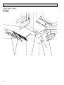
PC-4GJSA1
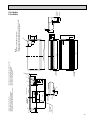
239
When electrical
box is pulled
down
42
Electrical box
93
6~7
1
Electrical box
525
160
3
2
229
1545
70
Celling
[ FRONT VIEW ]
2
8
38 140
38
86
138
171
263
687
5
1
4
1
236
Gap to ceiling
192
Air intake
Air outlet
45
1535
1620
1524
1547(suspension bolt pitch)
18
140
70
6
16
87
(3/8F liquid)
(3/4F gas)
(Drainage)
182
198
245
NOTES:
1. Use M10 or W3/8 screws for anchor bolt.
2. Please be sure when installing the drain-up machine (option parts).
refrigerant pipe will be only upper drain pipe arrangement.
80
320
207
680
150
5 Refrigerant-pipe connection (liquid pipe side/flared connection)
6 Knock out hole for upper drain pipe arrangement
7 Knock out hole for left drain pipe arrangement
8 Knock out hole for wiring arrangement
217
Drainage pipe connection (26mm I.D.)
Drainage pipe connection (for the left arrangement)
Knock out hole for left drain-piping arrangement
Refrigerant-pipe connection (gas pipe side/flared connection)
270
1
2
3
4
81 96
254
PC-5GJSA1
PC-6GJSA1
15
2.REMOTE CONTROLLER
12(15/32)
96.5
90.5
3
3.6
Upper side wiring
arrangement
opening
12(15/32)
8
Rear side wiring
arrangememt opening
6
COOL
10
27
DRY
9
26
FAN
8
25
7
24
6
23
5
22
4
21
3
20
2
19
1
18
TIMER/TEMP.
UP
POWER
HIGH
ON/OFF
46
28
MODE
SELECT
LOW
FAN
SPEED
ON
LOUVER
DOWN
AUTO
STOP
START
TIMER
MODE
4.6
29
11
83.5(3-9/32)
TEMP
12
108(4-1/4)
117(4-5/8)
69
TIMER
3
75
3
3
11.6
9.2
MITSUBISHI ELECTRIC
108(4-1/4)
117(4-5/8)
Fixing hole
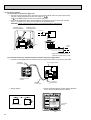
Remote controller cable installation
●For exposed remote controller cable installation
●For recessed remote controller cable installation
Exposed remote controller
cable
Remote controller cable
Conduit tube
(local arrangement)
TIMER
TEMP
12
29
11
28
COOL
10
27
DRY
9
26
8
25
7
24
6
23
5
22
4
21
3
20
2
19
1
18
TIMER/TEMP.
POWER
FAN
UP
HIGH
ON/OFF
MODE
SELECT
LOW
FAN
SPEED
ON
LOUVER
DOWN
AUTO
STOP
START
TIMER
MODE
MITSUBISHI ELECTRIC
Switch box
(local arrangement)
Cable connection is only from the top.
(right, left and bottom not possible)
Set screw (match with switch box),
local arrangement.
Note:The cable for the remote controller is 5m (16ft)and 12-core with connection O.D. 5.8.
16
6
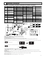
WIRING DIAGRAM
PC-2GJA1 / PC-2.5GJA1 / PC-3GJA1 / PC-4GJSA1 / PC-5GJSA1 / PC-6GJSA1
SYMBOL
NAME
C
SYMBOL
FAN MOTOR CAPACITOR
NAME
SYMBOL
NAME
SYMBOL
NAME
RUN INDICATOR LED
SWC<I.B>
OPTION SWITCH
CN120<I.B> REMOTE CONTROLLER TRANS- LD3<R.B>
COOLING INDICATOR LED
SW1<I.B>
FUNCTION SWITCH
MISSION WIRE CONNECTOR
LD4<R.B>
FAN MODE INDICATOR LED
SW2<I.B>
UNIT SWITCH
CN2<I.B>
TIMER ADAPTOR CONNECTOR
LD5<R.B>
FAN HIGH INDICATOR LED
SW3<I.B>
EMERGENCY OPERATION SWITCH
CN2A<I.B>
TRANSMISSION WIRE No.1
LD6<R.B>
LOUVER RUN INDICATOR LED
SW1<R.B>
ON / OFF SWITCH
CONNECTOR
LD7<R.B>
INDICATOR MODE TEMPERATURE LED
SW2<R.B>
OPERATION MODE SWITCH
TRANSMISSION WIRE No.2
LD8<R.B>
INDICATOR MODE TIMER LED
SW3<R.B>
FAN HIGH/LOW SWITCH
X1<I.B>
DRAIN-UP MACHINE RELAY
CN2B<I.B>
LD1<R.B>
TB4
INDOOR / OUTDOOR CONNECTING WIRE TERMINAL BLOCK
RT1
ROOM TEMPERATURE THERMISTOR
(0 /15k ,25 /5.4k
RT2
DETECT)
INDOOR COIL THERMISTOR
(0 /15k ,25 /5.4k
DETECT)
CONNECTOR
LD9<R.B>
DRY INDICATOR LED
SW4<R.B>
LOUVER ON / OFF SWITCH
X4<I.B>
FAN MOTOR RELAY
CNP<I.B>
DRAIN-UP MACHINE CONNECTOR
LD10<R.B>
FAN LOW INDICATOR LED
SW5<R.B>
INDICATOR SWITCH
ZNR
VARISTOR
CN28<I.B>
TIME SHORTENING CONNECTOR LD11<R.B>
OFF TIMER INDICATOR LED
SW6<R.B>
TEMPERATURE / TIMER
DP
OPTION DRAIN-UP MACHINE
CN50<I.B>
DRAIN SENSOR CONNECTOR
LD12<R.B>
SETTING UP SWITCH
DS
OPTION DRAIN SENSOR
CN51<I.B>
MULTIPLE CONNECTOR
LD13-24<R.B> TEMPERATURE / TIMER RE-
TEMPERATURE / TIMER
W/B
OPTION WIRELESS REMOTE
ON TIMER INDICATOR LED
CN120<R.B> REMOTE CONTROLLER TRANS-
SW7<R.B>
CONTROLLER BOARD
SETTING DOWN SWITCH
MAINING TIME INDICATOR LED
MISSION WIRE CONNECTOR
MF
FAN MOTOR
SW8<R.B>
TIMER CONTINUOUS ON / OFF SWITCH CNB(W.B)
F1,2<I.B>
FUSE (6.3A 250V)
MV
VANE MOTOR
R.B
REMOTE CONTROLLER BOARD
LED1(W.B)
RUN INDICATOR LED
CN70<I.B>
WIRELESS REMOTE CONT-
SWA<I.B>
HIGH CELING TYPE SWITCH
T
TRANSFOMER
SW2(W.B)
COOL OPERATION SWITCH
ROLLER CONNECTOR
JR<I.B>
FUNCTION SELECTOR
TB2
POWER SUPPLY TERMINAL BLOCK RU(W.B)
I.B
L
N
RED
ORN
YLW
1 3 5
CNP 1 3
D.U.M
CND 1 3
6
RED
RED
BRN
BRN
TRANS
ON
OFF
1 2 34 5 6 7 8
ON
OFF
1 2 34 5 6 7 8
1 2 34 5 6 7 8
LD8
LD7
SW5
SW1
CN120
LD1
SW2
SW3
SW4
SW8
LD3
LD9
LD4
LD5
LD6
LD10
LD11
RT1
SW6
SW7
RT2
LD12
STD
OP
BLK
BLK
2
1
R.B
LD13
LD14
LD15
LD16
LD17
LD18
LD19
LD20
LD21
LD22
LD23
LD24
12345
YLW
TO OUTDOOR UNIT
CONNECTING WIRES
DC12V
CN28
12345678
L.TEST
1 2 34 5 6
INTAKE
3
2
1
OUTDOOR UNIT
ORN TB4
2 1
SW2
CN2
TWIN-1
SW1
ON
OFF
TIMER
TWIN-2
JR
SWC
CN2A
CN20
SWA
CN2B
1 2 34 5 6 7 8
6GJSA1
Remote control transmissing wire 12VDC with 12 core connector
2 1
PIPE
WIRELESS
123
1 2 34 5 6 7 8
5GJSA1
REMOTE CONTROLLER
12
1 3 2 1
CN21
2 1
CN50
DRAIN
CN30
OUTDOOR
CN51
MULTIPLE
5 4 3 2 1
CN70
1 2 34 5 6 7 8
4GJSA1
INDOOR UNIT
12
TO.RC
1
CN6V
SW3
ON
OFF
TRANS
ZNR
ON
OFF
3GJA1
2.5GJA1
ON
OFF
ON
OFF
SW1
fig:*3
F1
VANE
X1
MV
4 3 2 1 CN4T
X1
X4
2GJA1
ON
OFF
SW1
Service Ref.
6
T
6
X4
Service Ref.
TB2
CN120
F2
GRN/YLW
1 3 CNT
POWER
POWER SUPPLY
(1 PHASE)
AC220-240V 50Hz
AC220V 60Hz
14.7VAC
WHT
YLW
RED
BLU
RED
WHT
BLK
C
11.8VAC
220V
230V
240V
MF
FAN1
BEAM RECIEVE UNIT
JUMPER RESISTORS
INDOOR CONTROLLER BOARD
I.B
INDOOR BOARD CONNECTOR
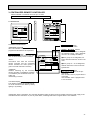
[Emergemcy operation procedure]
(2) Turn on outdoor unit side circuit breaker, then indoor unit side circuit breaker in this order.
(3) During emergency operation, indoor fan runs at high speed but automatic vane remains stop.
(4) If vane closed, open the vane by hand slowly.
(5) Thermostat will not function.
(6) Emergency cooling should be limited to 10 hours maximum (The Indoor unit heat exchanger may freeze).
(7) If the ,microcomputer doctor detects the abnomality of the drain-up machine during cool mode. do not execute emergency operation (It causes drain overflow).
NOTES :
1. Since the indoor fan motor (MF) is connected with 220V power, using 230, 240V power will require a setting change of the dip switch (SW1<I.B>) on the indoor controller board
as shown in fig : w1.
fig : w1
SW1
ON
ON
Indoor fan motor (MF) for 230, 240V.
OFF
1 2 3 4 5 6 7 8
OFF
1 2 3 4 5 6 7 8
2. Since the indoor transformer (T) is connected with 220V power, if 230, 240V power used. Change the wiring connection showing fig : W2.
fig : w2
When power supply is
240V
230V
240
YELLOW
230
ORANGE
220
RED
3. Since the outdoor side electric wiring may change be sure to check the outdoor unit electric wiring for servicing.
4. Symbols used in wiring diagram above are.
: Connector ,
: Terminal block
5. Emergency operation
If remote controller or microcomputer fails but there is no other trouble,. emergency operation is possible by setting dip switch (SW3<I.B>) on the indoor controller board.
[Check items]
(1)Compressor and fan.
(2)Check the abnomality using self diagnostic function. When the result of self diagnosis indicates protective device such as freeze protection, emergency operation is not possible
unless the cause is removed.
(3)Emergency operation will be continuous operation mode due to power ON/OFF (ON/OFF with remote controller is not possible).
[Emergency operation procedure]
(1)Set the dip switch(SW3<I.B>) on the indoor controller board to1 2 onand 3 off for cooling.
17
7
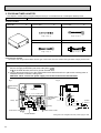
REFRIGERANT SYSTEM DIAGRAM
PC-2GJA1 / PU-2NJA1, PU-2VJA2
Refrigerant pipe 15.88 (5/8)
(With insulator) option
Flexible tube
Low pressure
switch
Ball
valve
Check
plug
High
pressure
switch
Charge
plug
Outdoor heat
exchanger
Indoor heat
exchanger
Flared
connection
Strainer
Flared
connection
Distributor
with strainer
Accumulator
Compressor
Capillary tube
for injection
O.D.4
Ball valve
(with service port)
I.D.2 –R430
flow of refrigerant
Refrigerant pipe 9.52 (3/8)
(With insulator) option
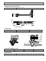
PC-2.5GJA1, PC-3GJA1, PC-4GJSA1 / PU-2.5NJA1, PU-2.5VJA2, PU-3NJA1,PU-3VJA2,
PU-3YJA3,PU-4TJSA2, PU-4VLJSA2, PU-4YJSA3
PC-2.5/3GJA
PC-4GJA
Refrigerant pipe 15.88 (5/8)
Refrigerant pipe 19.05 (3/4)
Flexible tube
Low pressure
switch
Ball
valve
Indoor heat
exchanger
Indoor coil
thermistor
RT2
Thermal switch
(Only PU-4VLJSA)
Charge
plug
High pressure
switch
Check
plug
Strainer
Flared
connection
Outdoor heat
exchanger
Flared
connection
Accumulator
Compressor
Capillary tube for
injection
Distributor
with strainer
w
Capillary
tube
Only PU-2.5
PU-3
PU-4YJSA,
4TJSA
Ball valve
(with service port)
Refrigerant pipe 9.52 (3/8)
(With insulator) option
18
flow of refrigerant
w
Capillary tube size
PU-2.5 (O.D.3.2 I.D.1.6 –R760) 2pcs
PU-3 (O.D.3.2 I.D.1.8 –R800) 2pcs
PU-4YJSA, 4VLJSA, 4TJSA (O.D.3.2 I.D.2.0 –R840)
2pcs
PC-5GJSA1, 6GJSA1 / PU-5YJSA, PU-5TJSA
PU-6YJSA, PU-6TJSA
INDOOR UNIT
Refrigerant pipe 19.05 (3/4F)
(With insulator) option
Flexible tube
Distributor
with strainer
Check plug
Charge
plug
Ball
valve
Indoor heat
exchanger
OUTDOOR UNIT
Thermal
switch
Outdoor heat
exchanger
High
pressure
switch
Flared
connection
Flared
connection
Accumulator
Compressor
Capillary tube
PU-5Y·TJSA
(O.D. 4.0 oI.D. 2.4 –R840)o2pcs
PU-6YJSA
(O.D. 4.0 oI.D. 2.4 –R1200)o2pcs
PU-6TJSA
(O.D. 4.0 oI.D. 2.4 –R740)o2pcs
Ball valve
(with service port)
Refrigerant pipe 9.52 (3/8F)
(With insulator) option
Strainer
DPR
Capillary tube
PU-5Y·TJSA (O.D. 4.0 oI.D. 2.4 –R400)
PU-6Y·TJSA (O.D. 4.0 oI.D. 2.4 –R200)
: flow of refrigerant
19
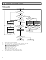
8
OPERATION FLOW-CHART
Models : PC-GJA
1. Main operation
Start
1
NO
POWER SUPPLY
Live
YES
<w1>
TIMER MODE
button ON
YES
NO
During
operation
<w2>
NO
Protection device
Self hold reset
ON/OFF
button ON
YES
YES
STOP
<w3>
YES
Protection device
Self hold
Abnormal
operation mode
NO
NO
AUTO STOP lamp ON
AUTO START lamp ON
Auto stop timer
1 12Hr up/ press
12 1Hr down/ press
Auto start timer
1 12Hr up/ press
12 1Hr down/ press
Set time Elapsed time=0
Set time Elapsed time=0
YES
POWER lamp ON
Self-diagnostic function
Indicate & Memory
EMERGENCY
ALL STOP
NO
STOP
<w4>
<w5>
MODE SELECT
button
DRY
COOL
COOL OPERATION
w1
w2
w3
w4
20
DRY OPERATION
Refer to page 26 for timer mode details.
The unit starts operation by pressing the ON / OFF switch when unit is OFF.
The factors which cause "abnormal operation mode" are as follows.
●Outdoor unit abnormal operation.
●Fault of room temperature thermistor (RT1).
●Fault of indoor coil thermistor (RT2).
●Indoor coil frost protection mode.
●Drain water overflow prevention mode.
Refer to page 28 for abnormal operation mode details.
The compressor will not start for 3 minutes after the stop.
YES
NO
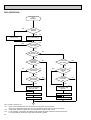
COOLING OPERATION
COOL operation
NO
Initial
COOLING
w8
YES
Vane initial
setting
NO
Fan speed
LOW
YES
NO
Downward discharge
1 hour
YES
Vane horizontal
airflow
Vane setting notch
w9
NO
Compressor
thermostat
ON
NO
Allowance
cancel
NO
YES
YES
3-minute
time delay
YES
6-minute
time delay
NO
3-minute
compressor
operation
NO
NO
w10
YES
Allowance
period
NO
6 minute
time delay
Allowance set
YES
Coil frost protection
YES
Coil frost
prevention
NO
w11
NO
Cooling area
NO
YES
10-minute
compressor
operation
YES
NO
1 min continue
YES
Allowance cancel
FAN speed
LOW
Coil frost
protection
NO
YES
NO
16-minute
compressor
operation
Indoor coil NO
tempreature is
10°C or higher
YES
Indoor pipe
temperature is
1°C or lower
NO
Compressor ON
YES
YES
Coil frost
prevention
FAN speed
LOW 5 min
elapse
NO
YES
Outdoor unit
trouble
3-minute
time delay
Coil frost
prevention release
Compressor OFF
1
w8 When operation stops or changes to cooling or dry mode, the auto vane turns to a horizontal angle. If operation changes
during auto vane SWING, the auto vane will continue to swing.
w9 When operating TEST RUN, the thermostat will be continuously ON.
w10 After 3 minute compressor operation, if the indoor coil thermistor reads -15°C or below for 3 minutes, the compressor will
stop for 6 minutes.
w11 Cooling area : Indoor coil temperature is more than 5 degrees above the room temperature.
FAN area
: Indoor coil temperature is within 5 degrees either way of the room temperature.
21
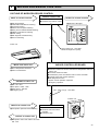
DRY OPERATION
DRY
operation
NO
Initial dry
operation
w8
YES
Vane
setting notch
Vane initial setting
YES
Room tempereature is
18°C or lower
w12
NO
NO
During
compressor ON
YES
3-minute
compressor
operation
NO
NO
YES
NO
w9
Compressor &
thermostat ON
YES
Compressor &
thermostat
ON
NO
Compressor ON
time completes
10-minute
compressor
OFF
NO
YES
YES
w13
10-minute compressor
OFF timer start
Compressor ON
time set
Compressor OFF
Compressor ON
w14
w14
Fan speed LOW
1
w8—9 Refer to page 24~25.
w12
When room temperature is 18°C or below, the compressor cannot operate.
When room temperature rises over 18°C, the compressor starts after a 3-minute time delay.
w13
Compressor ON time is decided by room temperature. Refer to page 24~25.
w14
In dry operation, compressor ON makes the fan speed LOW and compressor OFF stops the fan.
It is not possible to set the fan speed with the remote controller
22
w9
NO
YES
Fan STOP
YES
3-minute
time delay
9
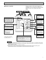
MICROPROCESSOR CONTROL
1.OUTLINE OF MICROPROCESSOR CONTROL
REMOTE CONTROLLER
INPUT to remote controller
OUTPUT to remote controller
● Transmits and receives orders.
● OFF-ON switching.
● COOL/DRY-FAN selector switching.
● Thermostat setting.
● HIGH-LOW fan speed switching.
● Swing louvers SWING-FIXED switching.
● TIMER mode selector switching.
● Timer setting.
● Self diagnostic troubleshooting.
● Test run switching.
● Indication LED lights.
TIMER
TEMP
12
29
11
28
COOL
10
27
DRY
9
26
FAN
8
25
7
24
6
23
5
22
4
21
3
20
2
19
1
18
TIMER/TEMP.
UP
POWER
HIGH
ON/OFF
MODE
SELECT
LOW
FAN
SPEED
ON
LOUVER
DOWN
AUTO
STOP
START
TIMER
MODE
MITSUBISHI ELECTRIC
Indoor unit
12VDC
Polar, twelve (12) - core cable
Maximum length 50m (164ft)
INDOOR CONTROLLER BOARD
INPUT from indoor unit
● Room temperature thermistor.
● Indoor coil thermistor.
● Receives orders from remote controller and temperature data from
indoor unit.
● Processes orders and data.
● Transmits the power of indication LED to remote controller
● Controls indoor and outdoor operation.
● Self diagnostic function.
w System control operation.<Optional>
w Emergency operation.
OUTPUT to indoor unit
Fan : ON - OFF.
Fan speed : HIGH - LOW
Swing louver : ON-OFF
Emergency stop.
Non - polar, two (2) - core cable
12VDC
●
●
●
●
INPUT from outdoor unit
● Compressor protection device working
Outdoor unit
OUTDOOR UNIT
● Receives order from indoor
controller.
● Emergency stop.
OUTPUT to outdoor unit
● Compressor motor and outdoor fan motor :
ON - OFF
23
2. INDOOR UNIT CONTROL
2-1COOL operation
<How to operate>
1 Press POWER ON/OFF button.
2 Press MODE SELECT button to set operation mode to COOL.
TIMER
TEMP
12
29
11
28
COOL
10
27
DRY
9
26
FAN
8
25
7
24
6
23
5
22
4
21
3
20
2
19
1
18
TIMER/TEMP.
POWER
UP
HIGH
ON/OFF
MODE
SELECT
LOW
FAN
SPEED
ON
LOUVER
3 Check
START
lamp is ON and set desired temperature with UP
or DOWN button.
NOTES : 1. When
TIMER
lamp is ON, press TIMER/TEMP button
to change the display to temperature mode.
2. Set temperature changes by 1°C in the range 18 ~ 29°C
each time UP or DOWN button is pressed.
3. The lighting lamp shows the set temperature, and the
flashing lamp shows the room temperature.
When the room temperature is equal to the set temperature, the lamp keeps lighting, 0.5 seconds brightly and
0.5 seconds faintly.
DOWN
AUTO
STOP
TEMP.
TIMER
MODE
MITSUBISHI ELECTRIC
<COOL operation time chart>
Operation starts by
POWER button
ON.
Room temperature
becomes equal to
set temperature.
Room temperature
rises above set
temperature.
Operation stops by
POWER button
OFF.
ON
Thermostat
OFF
LOW or HIGH
LOW or HIGH
ON
Indoor fan
OFF
Depends on remote controller setting
ON
Louver
OFF
Compressor
OFF
ON
MIN. 3 minutes w1
w1 Even if the room temperature rise above the set temperature during this period, the compressor will not start until this period has ended.
(1) Compressor control
1 3-minute time delay
To prevent overload, the compressor will not start within 3 minutes after stop.
2 The compressor runs when room temperature is higher than set temperature.
The compressor stops when room temperature is equal to or lower than the set temperature.
3 The compressor stops in check mode or during protective functions.
4 Coil frost prevention
To prevent indoor coil frost, the compressor will stop when the indoor coil thermistor (RT2) reads 1°C or below after the
compressor has been continuously operated for at least 16 minutes or more. The coil frost prevention is released under any
of the following conditions.
● The indoor coil thermistor rises to 10°C or above.
● The room temperature becomes equal to or lower than the set temperature.
● COOL mode is stopped or changed to another mode.
NOTE : By cutting the jumper wire JRO2 on the indoor controller board, the temperature to start coil frost prevention
changes from 1°C to -3°C.
5 Coil frost protectiony
When indoor coil temperatuer becomes -15°C or below, coil frost protection will proceed as follows.
<Start condition>
After the compressor has been continuously operated for 3 minutes or more, and the indoor coil temperature has been -15°C
or below for 3 minutes, the coil frost protection will start.
<Coil frost protection>
Compressor stops for 6 minutes, and then restarts.
If the start condition is satisfied again during the first 10 minutes of compressor operation, both the indoor and outdoor units
stop, displaying a check code of ¨P6¨ on the remote controller.
24
<Termination conditions>
Coil frost protection is released when the start condition is not satisfied again during the allowance, or when the COOL mode
stops or changes to another mode.
(2) Indoor fan control
Indoor fan speed LOW/HIGH depends on the remote controller setting.
However, if an outdoor unit abnormality is detected, the indoor fan speed will be LOW, regardless of the remote controller
setting.
(3) Louver control
Louver operation (SWING LOUVER ON / OFF) depends on the remote controller setting.
w Louver comes to the holizontal position automatically after 1 hour operation in law mode.
(4) Detecting abnormalities in the outdoor unit
After the compressor has been continuously operated for 3 minutes, if the difference between the indoor coil temperature
and room temperature is out of RANGE C for 1 minute, the indoor fan speed will turn to LOW. Five minutes later, if the difference is still out of RANGE C,the outdoor unit is functioning abnormally. Thus, the compressor will stops and the remote
controller still display this occurrence.
RANGE A : Indoor coil temperature is more than 5 degrees above room temperature.
RANGE B : Indoor coil temperature is within 5 degrees either way of room temperature.
RANGE C : Indoor coil temperature is more than 5 degrees below room tempetature.
(5) Drain pump control
The drain pump works in COOL or DRY operation. When COOL or DRY operation stops or changes to another mode, the
drain pump continues to operate for 3 more minutes.
<Drain sensor>
When both the drain pump and unit are operating, the drain sensor detects the temperature. This temperature tells
whether the drain water level is above or under the drain sensor. If the drain water level rises above the drain sensor due
to a drain pump malfunction, the unit will enter the check mode. The operation will stop and only the drain pump will continu to operate for 3 more minutes. When either of the following conditions are satisfied, the drain sensor is deamed to be
under water.
● Though the drain sensor has been heated by the drain sensor heater for more than 40 seconds, its temperature rise is
less than 20 degrees.
● The drain sensor temperature is below 63°C.
2-2 DRY operation
<How to operate>
1 Press POWER ON/OFF button.
2 Press MODE SELECT button to set operation mode to DRY.
TIMER
TEMP
12
29
11
28
10
27
9
26
8
25
7
24
6
23
5
22
4
21
3
20
2
19
1
18
TIMER/TEMP.
POWER
COOL
DRY
FAN
UP
HIGH
ON/OFF
MODE
SELECT
LOW
FAN
SPEED
ON
LOUVER
DOWN
AUTO
STOP
START
TIMER
MODE
MITSUBISHI ELECTRIC
3 Check
TEMP.
NOTES : 1. When
lamp is ON and set desired temperature with UP or DOWN button.
TIMER
lamp is ON, press TIMER/TEMP button to change the display
to temperature mode.
2. Set temperature changes by 1°C in the range 18 ~ 29°C each time UP or
DOWN button is pressed.
3. The lighting lamp shows the set temperature, and the flashing lamp shows the
room temperature.
When the room temperature is equal to the set temperature, the lamp keeps
lighting, 0.5 seconds brightly and 0.5 seconds faintly.
2-3 FAN operation
<How to operate>
1 Press POWER ON/OFF button.
2 Press MODE SELECT button to set operation mode to FAN.
TIMER
TEMP
12
29
11
28
COOL
10
27
DRY
9
26
FAN
8
25
7
24
6
23
5
22
4
21
3
20
2
19
1
18
TIMER/TEMP.
UP
POWER
HIGH
ON/OFF
MODE
SELECT
LOW
FAN
SPEED
ON
LOUVER
DOWN
AUTO
STOP
START
TIMER
MODE
MITSUBISHI ELECTRIC
NOTES : Temperature can not be set in FAN operation.
! Indoor fan control
The indoor fan speed LOW/HIGH depends on the remote controller setting.
@ Louver control
The louver operation ON/OFF depends on the remote controller setting.
# Drain pump control
The drain pump does not work in FAN operation. As an exception, when COOL mode
changes to FAN mode, the drain pump continues to operate for the first 3 minutes in FAN
operation.
25
2-4 TIMER operation
<Timer function>
AUTO STOP ·········The air conditioner stops after the set time lapses.
AUTO START ········The air conditioner starts after the set time lapses.
<How to operate AUTO STOP timer>
TIMER
TEMP
12
29
11
28
COOL
10
27
DRY
9
26
FAN
8
25
7
24
6
23
5
22
4
21
3
20
2
19
1
18
TIMER/TEMP.
UP
POWER
HIGH
1 While ● POWER lamp is lighting, press TIMER MODE button.
TIMER
AUTO
and
lamps turn ON.
STOP w
ON/OFF
MODE
SELECT
LOW
FAN
SPEED
ON
LOUVER
2 Set the time for the AUTO STOP timer with the UP or DOWN button.
NOTE : The time setting is in 1 hour units up to 12 hours.
3 With the lapse of time, the timer lamps turn OFF one by one, showing
the remaining time.
4 To cancel the AUTO STOP timer and continue operation, press the
TIMER MODE button.
To cancel the AUTO STOP timer and stop operation, press the
POWER ON/OFF button.
<How to operate AUTO START timer>
DOWN
AUTO
STOP
START
TIMER
MODE
MITSUBISHI ELECTRIC
1 While ● POWER lamp is OFF, press TIMER MODE button.
TIMER
AUTO
and
lamps turn ON.
START w I
2 Set the time for the AUTO START timer with the UP or DOWN button.
NOTE : The time setting is in 1 hour units up to 12 hours.
3 With the lapse of time, the timer lamps turn OFF one by one, showing
the remaining time.
4 To cancel the AUTO START timer and keep the unit OFF, press the
TIMER MODE button.
To cancel the AUTO START timer and start operation, press the
POWER ON/OFF button.
<Remaining time display>
The green lamps show the remaining time until the time is up. When the time is up, the green lamps are all off.
TIMER
Green
lamps
w
TEMP
TIMER
w
TEMP
TIMER
w
TEMP
TIMER
w
TEMP
12
29
12
29
12
29
12
29
11
28
11
28
11
28
11
28
10
27
10
27
10
27
10
27
9
26
9
26
9
26
9
26
8
25
8
25
8
25
8
25
7
24
7
24
7
24
7
24
6
23
6
23
6
23
6
23
5
22
5
22
5
22
5
22
4
21
4
21
4
21
4
21
3
20
3
20
3
20
3
20
2
19
2
19
2
19
2
19
1
18
1
18
1
18
1
18
Remaining time:2 hour
59 minutes to 2 hour
1 hour 59 minutes
to 1 hour
59 minutes to 0
Time counting
is completed.
NOTE : When AUTO STOP timer is active, the remaining time display can be changed to the temperature display by pressing
DISPLAY SELECT button.
26
2-5 Test run
The unit starts the test run by pressing both the UP and DOWN buttons simultaneously for more than two seconds during
TIMER
w
lamp ON or the unit OFF.
▲
● The test run automatically stops in 2 hours.
● Set temperature is not displayed during test run.
● To cancel the test run, press the POWER ON/OFF button.
<Initial setting>
The units are set as follows by the factory.
1) Initial operation mode: FAN
3) Swing louver
: OFF
2) Fan speed
: LOW
4) Set temperature: 28°C
2-6 Emergency operation
When the remote controller or microprocessor malfunctions and no other trouble exists, emergency operation
is available by setting the dipswitch on the indoor controller board.
[Check items]
! Make sure the compressor and the fans are running
normally.
@ Locate the trouble with the self-doagnostic function. If
the self-diagonostic function indicates that the protection device (such as coil frost protection)is functioning, the sources must be removed before attempting
emergency operation.
Emergency operation ON/OFF is activated not with
the remote controller but with the circuit breaker.
INDOOR CONTROLLER BOARD
SW3
[Emergency operation procedure]
! Cooling operation is available by setting the dipswitch
SW3 1 and 2 ON and 3 OFF on the indoor controller board.
@ To start emergency operation, turn the outdoor sidecircuit breakerON first, and then the indoor side circuit breaker ON.
# During emergency operation, the indoor fan runs on HIGH speed, the compressor runs continuously, and the louver
stops.
When the drain pump is attached, it works in emergency operation.
$ Thermostat will not function.
% Do not use emergency cooling operation for more than 10 hours, as the indoor coil may freeze.
w If the self-diagnostic function shows a drain pump malfunction, do not attempt emergency operation, as the drain may
overflow.
2-7 Auto Restart function
Unit can be start / stop by turning the breaker ON / OFF.
! Cutting the JR06 on the indoor board.
Unit can be start / stop using a remote controller. Only If the unit was already being operated before power off, the unit resta
automatically as soon as power is back.
JR06
Available
Not available
Auto restart
Not effective
Effective
@ Short all the CN2 on the indoor board.
Unit can not be start/ stop using remote controller.
Unit will restart automatically whether the unit is
operated or stopped when the power is cut off.
Optional timer adapter
PAC-SA89TA-E
ORN
BRN
RED
1
CN2 2
3
I.B.
27
2-8 Function of jumper wire and dipswitch on indoor controller board
1. Jumper wire
1 JR1...Jumper wire for the auto vanes.
Cut JR01 for the unit WITHOUT auto vanes.
2 JR2...Jumper wire for the temperature to start coil frost prevention
Cutting JR02 changes the temperature from +1°C to -3°C.
3 JR3...Jumper wire for set temperature adjustment in HEAT mode.
In HEAT operation, heated air stagnates in the upper part of the room. The indoor unit installed in the upper part of the
room will detect the air temperature higher than the actual temperature in the living space. This difference is about 4
degrees. Therefore, the temperature detected by the room temperature thermistor should be corrected 4 degrees down.
The unit with JR04 attached will make this adjustment.
4 JR4...Jumper wire for the indoor fan speed during thermostat OFF in HEAT mode
Cutting JR04 changes the speed from Extra-Low to Low.
5 JR5...Jumper wire for detecting abnormalities in the outdoor unit
Cutting JR05 makes this detection unavailable. (Occurrence of abnormality can not be detected. )
6 JR6...Jumper wire for auto restart function
Cutting JR06 makes the auto restart function available.
2. Dipswitch
1 SW1 (Function switch)
SW1-1) Switch for power supply
ON : 220V
OFF : 230V, 240V
SW1-2) Switch for single or twin control
ON : Twin control
OFF : Single control
SW1-3) Switch for unit number in twin control
(This switch is valid when SW1-2 is ON. )
ON : Unit No. 2
OFF : Unit No. 1
SW1-4, SW1-5,SW1-6) Switch for capacity of each model
ON
OFF
1 2 3 4 5 6 7 8
PC-2GJA1
PC-2.5GJA1
ON
OFF
PC-3GJA1
ON
OFF
4 5 6
ON
OFF
ON
OFF
4 5 6
SW1-7, SW1-8)
PC-4GJSA1
ON
OFF
4 5 6
PC-5GJSA1
ON
OFF
4 5 6
PC-6GJSA1
ON
OFF
4 5 6
Pair number of the wiress remote controller
ON
OFF
7 8
0
2 SW2 (Unit switch)
ON
OFF
7 8
1 2 3 4 5
7 8
1
2
SW2-1)
SW2-2)
ON
OFF
ON
OFF
SW2-3)
SW2-4)
SW2-5)
7 8
3
Switch for air conditioner with or without electric heater
ON : Unit with electric heater
OFF : Unit without slectric heater (PC-GJ(S)A)
Switch for air conditioner with or without heat pump
(Keep this switch OFF for PC-GJ(S)A)
ON : Unit with heat pump OFF : Unit without heat pump
Switch for function code (Keep this switch OFF for PC-GJ(S)A)
ON : 1
OFF : 0
Switch for function code (Keep this switch OFF for PC-GJ(S)A)
ON : 1
OFF : 0
Switch for function code (Keep this switch ON for PC-GJ(S)A)
ON : 1
OFF : 0
3 SW3 (Emergency operation switch)
Normal operation
For emergency cooling
1 2 3
ON
OFF
4 SWA : for ceiling height
3...High ceiling
2...Standard
1...Low ceiling
28
1 2 3
ON
OFF
5 SWC : optional filter element
STD...Without filter element
OP...With filter element
For ceiling height
High ceiling
3.5m
Standard
2.8m
Low ceiling
2.3m
4 5 6
10
TROUBLESHOOTING
1. self-diagnostic function
! When trouble occurs during operation, the unit stops and enters the self-diagnostic mode, and displays the trouble location with the timer lamps on the remote controller. All the other lamps are OFF.
@ To activate the self-diagnostic function for service, press the UP and DOWN buttons simultaneously for more than two
TIMER
w
▲
seconds during operation with
lamp ON.
# The timer lamps show the latest trouble. Trouble data is memorized until the next trouble occurs, even when the breaker
turns OFF. To clear the memory, press the UP and DOWN buttons simultaneously for more than two seconds during the
test run.
$ All buttons except the POWER ON/OFF button are unavailable during the self-diagnostic mode.
% To release the self-diagnostic mode, press the POWER ON/OFF button.
Unit Trouble location
TEMP.
i
▲
TIMER
w
Transmission error
in twin control
▲
29
11
28
10
27
9
26
8
25
7
24
6
23
5
22
4
21
3
20
2
19
1
18
Unit
No.2
● Poor connector contact
● Thermistor malfunction
● Check connector
● Check thermistor
➔ No trouble ➔ replace indoor
controller
board.
● Poor connector contact
● Thermistor malfunction
● Check connector
● Check thermistor
➔ No trouble ➔ replace indoor
controller
board.
● Poor connector contact
● Thermistor malfunction
● Check connector
● Check thermistor
➔ No trouble ➔ replace indoor
controller
board.
Drain
overflow
protection
● Drain pump malfunction
● Drain sensor improperly
mounted
● Check drain pump
● Check drain sensor
➔ No trouble ➔ replace indoor
controller
board.
Coil frost
or overheat
prevention
● Air passage short cycle
● Air filter clogged
● Indoor fan malfunction
● Remove blockage
● Check air filter
● Check indoor fan
Indoor coil
thermistor
(RT2)
Unit
No.1 Drain sensor
(DS)
Unit
No.2
Unit
No.1
Unit
No.2
Unit
No.1
Unit
No.2
● Check dipswitch setting
● Check wiring
● Check wiring
● Check outdoor unit
● Check outdoor coil thermistor
Unit
Room
No.1 temperature
thermistor
Unit
(RT1)
No.2
Unit
No.1
Measures
● Wrong wiring between
indoor/outdoor units
● Outdoor unit abnormality
detection
● Malfunction of outdoor coil
thermistor
● Reversed phase detected
Outdoor unit
12
Cause
● Wrong wiring between No. 1
and No. 2 units
● Poor connector contact
(Indicates that the unit is in self-diagnostic mode)
29
11
DISASSEMBLY PROCEDURE
PC-3GJA1
OPERATING PROCEDURE
1. Removing the air intake grill
(1) Slide the intake grill holding knobs (at two locations) backward to open the intake grill.
(2) When the intake grill left open, push the stoppers on the
rear hinges (at two locations) to pull out the intake grill.
PHOTOS&ILLUSTRATIONS
Figure 1
intake grill
slide
intake grill
holding knobs
Hinges
Pull out the intake grill
2. Removing the electrical box
(1) Remove the air intake grill.
(2) Remove the screw from the beam and remove the beam.
(3) Remove the screws from the electrical cover, and remove
the electrical cover.
(4) Disconnectors including CN6V and CN21.
(5) Remove the screws from the electrical box and pull out
the electrical box.
<Electrical parts in the electrical box>
Terminal block (for power supply)
Terminal block (for in/outdoor connecting wire)
Operation condenser
Indoor control board
Power Trans
Figure 2
beam
Slide to the left
screw(electrical cover)
clamp
electrical cover
screw(electrical box)
Photo 1
Operation
condenser
Power
trans
Terminal
block
(remote control)
Indoor
control
board
30
Terminal
block
terminal
(power supply)
block
(in / out conncting)
OPERATING PROCEDURE
3. Removing the fan motor
(1) Remove the intake grill.
(2) Disconnect the fan motor connector.
(3) Unscrew screws for removing the motor guard.
(4) Unscrew screws for removing the fan guard.
(5) Remove the screw for removing the motor support at both
left and right side.
(6) Loosen the set screws at the fan motor side of the connecting joint.
(7) Slide the fan motor to the left side and pull it out.
PHOTOS&ILLUSTRATIONS
Photo 2
Motor gurd
Screws
Motor
Set screws
Motor support
4. Removing the sirocco fan
(1) Remove the air intake grill.
(2) Remove 1 beam.
(3) Unscrew screws for removing the motor guard.
(4) Unscrew screws for removing the fan guard.
(5) Remove the lower casing while pressing the stoppers at
upper side of the casing.
(6) Loosen the set screws at the connecting joint.
(7) Remove the sirocco fan and shaft together by sliding the
shaft to the left.
Connecting joint
Photo 3
Fan guard
Motor guard
(Note)
Make sure that the upper side casing is snaped to the fan
plate securely with catch.
Sirocco fan
Motor
Casing
Bearing
Connecting joint
5. Removing the side panel
(1) Remove the air intake grill.
(2) Remove the screw from the side panel, and remove the
side panel by sliding the panel to the front.
Figure 2
side panel
sliding the panel
to the front
screw
31
OPERATING PROCEDURE
6. Removing the vane motor
(1) Remove the air intake.
(2) Remove the left side panel.
(3) Remove the relay connector of vane motor.
(4) Remove the electrical box.
(5) Remove the screws of vane motor, then remove vane
motor.
(Note)
Connect the lead wires and connectors properly and place
them in the proper position so that the wires are not pinched
by other parts.
PHOTOS&ILLUSTRATIONS
Photo 4
Screw
Relay connector of
the vane motor
Vane motor
7. Removing the indoor coil thermistor
(1) Remove the air intake grill.
(2) Remove the right side panel.
(3) Remove the relay connector of the indoor coil thermistor.
(4) Remove the screw, and remove the check panel.
(5) Extract the indoor coil thermistor from the holder.
<Caution for the installation>
There is a possibility for the short circuit when connector gets
wet by water through the thermistor lead wire.
Therefore, lead wire of the indoor coil thermistor should be
traped as shown in the picture.
Photo 5
Screw
Check
panel
Relay connector of
the pipe thermistor
Left side
panel
Photo 6
Hold
8. Removing the under panel
(1) Remove the air intake grill.
(2) Remove the beam.
(3) Remove the side panel (right and left).
(4) Unscrew the screws of the under panel, then remove the
lower panel.
wWeight of the lower panel : app. 2kg.
Photo 7
indoor coil thermistor
Screw
Under panel
32
Trap
OPERATING PROCEDURE
9. Removing the drain pan
(1) Remove the air intake grill.
(2) Remove the beam.
(3) Remove the side panel (right and left).
(4) Remove the under panel. Remove the screws of the right
and left side drain pan.
(5) Remove the insiation in center of the drain pan, and after
removing the screw, remove the drain pan.
PHOTOS&ILLUSTRATIONS
Photo 8
(Note)
Please aware that there might be drain left in the drain pan
when you remove the drain pan.
Screw
10. Removing the guide vane
(1) Remove the intake grill.
(2) Remove the beam.
(3) Remove the side panel (right and left).
(4) Remove the under panel.
(5) Remove the drain pan.
(6) Remove the screw from the guide vane, then remove the
guide vane.
Drain pan
Screw
Photo 9
Drain pan
11. Removing the Auto vane
(1) Remove the intake grill.
(2) Remove the left side panel.
(3) Remove the left side box.
(4) Remove the under panel.
(5) Remove the screw from the auto vane.
(6) Slide the auto vane to the right side and pull the auto vane
out.
Screw
(Insulation)
Screw
Guide vane
Photo 10
Screw
Auto vane
33
OPERATING PROCEDURE
12. Removing the heat exchanger
(1) Remove the air intake grill.
(2) Remove the beam.
(3) Remove the side panel. (right and left)
(4) Disconnect the relay connector.
(5) Remove the under panel.
(6) Remove the drain pan.
(7) Unscrew the screw of the pipe cover, and remove the pipe
cover.
(8) Unscrew the screw of the pipe support, and remove the
pipe support.
(9) Unscrew the screw of the heat exchange, and remove the
heat exchanger.
Remove the heat exchange with care, since this is quite
heavy. Removing work should be done with more than 2
people.
w Weight of heat exchanger : ApR.5.3kg.
34
PHOTOS&ILLUSTRATIONS
Photo 11
Pipe
support
Screws
Pipe cover
Screws
Heat
exchanger
12
PARTS LIST
FAN PARTS
PC-2GJA
PC-2GJA1
9
6
4
5
2
13
8
4
1
3
5
12
11
10
7
Part numbers that are circled not shown in the figure.
Q'ty / set
No.
Part No.
Part Name
Specification
PC-2
GJA, GJA1
1 T7W 23J 762 FAN MOTOR
D09B4P54MS
1
2 R01 17J 130 MOTOR LEG
1
3 R01 43E 126 PIECE (MOTOR)
1
4 R01 17J 110 CASING
2
5 R01 17J 114 SIROCCO FAN
2
6 R01 17J 202 INDOOR COIL THERMISTOR
1
7 R01 17J 529 DRAIN PAN ASSY
1
8 R01 18J 202 ROOM TEMPERATURE THERMISTOR
1
9 T7W 26J 480 HEAT EXCHANGER
1
10 R01 17J 524 DRAIN PLUG
1
11 T7W 17J 675 FAN GUARD
1
12 T7W 18J 675 FAN GUARD
1
13 T7W 19J 675 FAN GUARD
1
Remarks
(Drawing No.)
Wiring RecomDiagram mended
Symbol Q'ty
Price
Unit Amount
MF
RT2
RT1
35
FAN PARTS
PC-2.5GJA, PC-2.5GJA1
PC-3GJA, PC-3GJA1
11
18
5
9
1
2
10
4 •14
13
6
8
17
7
15
12
3
16
Part numbers that are circled not shown in the figure.
Q'ty / set
No.
Part No.
Part Name
Specification
PC-2.5
PC-3
GJA,GJA1 GJA,GJA1
Remarks
(Drawing No.)
Wiring RecomDiagram mended
Symbol Q'ty
MF
1
1
2 R01 29J 116 FAN JOINT
1
1
3 R01 29J 100 SHAFT (FAN)
1
1
4 R01 705 103 SLEEVE BEARING
1
1
5 R01 29J 130 MOTOR LEG
1
1
6 R01 29J 114 SIROCCO FAN
2
2
7 R01 33J 114 SIROCCO FAN
1
1
8 R01 17J 110 CASING
3
3
9 R01 17J 202 INDOOR COIL THERMISTOR
1
1
RT2
10 R01 18J 202 ROOM TEMPERATURE THERMISTOR
1
1
RT1
T7W 29J 480 HEAT EXCHANGER
1
1 T7W 30J 762 FAN MOTOR
11
DC9C4P70MS
1
T7W 33J 480 HEAT EXCHANGER
12 R01 29J 529 DRAIN PAN ASSY
1
1
13 R01 17J 524 DRAIN PLUG
1
1
14 R01 29J 145 BEARING SUPPORT
1
1
15 T7W 20J 675 FAN GUARD
1
1
16 T7W 21J 675 FAN GUARD
2
2
17 T7W 18J 675 FAN GUARD
1
1
18 R01 43E 126 PIECE (MOTOR)
1
1
36
Price
Unit Amount
FAN PARTS
PC-4GJSA
PC-4GJSA1
11
18
5
9
1
2
10
4 •14
13
6
8
17
7
15
12
3
16
Q'ty / set
No.
Part No.
Part Name
Specification
PC-4
GJSA, GJSA1
1 T7W 39J 762 FAN MOTOR
D10B4P90MS
1
Remarks
(Drawing No.)
Wiring RecomDiagram mended
Symbol Q'ty
Price
Unit Amount
MF
2 R01 29J 116 FAN JOINT
1
3 R01 29J 100 SHAFT
1
4 R01 705 103 SLEEVE BEARING
1
5 R01 35J 130 MOTOR LEG
1
6 R01 35J 114 SIROCCO FAN
2
7 R01 39J 114 SIROCCO FAN
1
8 R01 35J 110 CASING
3
9 R01 17J 202 INDOOR COIL THERMISTOR
1
RT2
10 R01 18J 202 ROOM TEMPERATURE THERMISTOR
1
RT1
11 T7W 37J 480 HEAT EXCHANGER
1
12 R01 35J 529 DRAIN PAN ASSY
1
13 R01 17J 524 DRAIN PLUG
1
14 R01 35J 145 BEARING SUPPORT
1
15 T7W 22J 675 FAN GUARD
1
16 T7W 23J 675 FAN GUARD
2
17 T7W 24J 675 FAN GUARD
1
18 R01 43E 126 PIECE (MOTOR)
1
37
FAN PARTS
PC-5GJSA,PC-6GJSA
PC-5GJSA1,PC-6GJSA1
12
20
10
11
19
16
17
4·15
14
18
13
Q'ty / set
No.
Part No.
Part Name
1 T7W 43J 762 FAN MOTOR
Specification
PC-5
PC-6
GJSA,
GJSA1
GJSA,
GJSA1
Remarks
(Drawing No.)
Wiring RecomDiagram mended
Symbol Q'ty
MF
1
1
2 R01 29J 116 FAN JOINT
1
1
3 R01 29J 100 SHAFT
1
1
4 R01 705 103 SLEEVE BEARING
1
1
5 R01 41J 130 MOTOR LEG
1
1
6 R01 41J 114 SIROCCO FAN
1
1
7 R01 39J 114 SIROCCO FAN
1
1
8 R01 35J 114 SIROCCO FAN
2
2
9 T7W B07 110 CASING
4
4
10 R01 17J 202 INDOOR COIL THERMISTOR
1
1
RT2
11 R01 14N 202 ROOM TEMPERATURE THERMISTOR
1
1
RT1
T7W 41J 480 HEAT EXCHANGER
1
12
D10B4P150MS
T7W 45J 480 HEAT EXCHANGER
1
13 R01 41J 529 DRAIN PAN ASSY
1
1
14 R01 17J 524 DRAIN PLUG
1
1
15 R01 35J 145 BEARING SUPPORT
1
1
16 T7W 25J 675 FAN GUARD
1
1
17 T7W 23J 675 FAN GUARD
2
2
18 T7W 24J 675 FAN GUARD
1
1
19 T7W 26J 675 FAN GUARD
1
1
20 R01 43E 126 PIECE (MOTOR)
1
1
38
Price
Unit Amount
ELECTRICAL PARTS
PC-2GJA, PC-2GJA1
PC-2.5GJA, PC-2.5GJA1
PC-3GJA, PC-3GJA1
PC-4GJSA, PC-4GJSA1
PC-5GJSA, PC-5GJSA1
PC-6GJSA, PC-6GJSA1
5
4
3
2
1
6
7
9
8
10
Q'ty / set
No.
Part No.
Part Name
Remarks
Specification PC-2 PC-2.5/3 PC-4 PC-5/6
GJA
GJA
GJSA GJSA (Drawing No.)
1 T7W 27K 310 CONTROLLER BOARD
2 T7W 520 239 FUSE
250V 6.3A
3 T7W 23J 260 TRANSFORMER
4
—
CONTROL BOX
R01 30L 255 CAPACITOR
3+ 400V
Wiring RecomDiagram mended
Symbol Q'ty
GJA1
GJA1
1
1
1
1
I.B
1
1
1
1
F1,2<I.B>
1
1
1
1
T
1
1
1
1
(BG00N015G12)
C
1
1
T7W 43J 255 CAPACITOR
C
1
C
6 T7W 521 716 TERMINAL BLOCK
3P(L,N,;)
1
1
1
1
TB2
7 T7W 512 716 TERMINAL BLOCK
2P(1,2)
1
1
1
1
TB5
1
—
8
—
(BG02A804G12)
1
BOX COVER
(BG02A804G14)
1
1
—
Unit Amount
GJSA1 GJSA1
1
5 T7W 39J 255 CAPACITOR
Price
9 T7W 20K 200 REMOTE CONTROLLER
1
1
1
1
10 T7W 139 305 REMOTE CONTROLLER CORD 12m
1
1
1
1
(BG02A804G13)
R.B
39
STRUCTURAL PARTS
PC-2GJA
PC-2GJA1
2
19 13 15
4
12
16
28
24
10
11
5
23
17
14
7
18
8
1
26
25
9
40
6
27
3
20
Part numbers that are circled not shown in the figure.
Q'ty / set
No.
Part No.
Part Name
Specification
PC-2
GJA, GJA1
1
R01 17J 661 RIGHT SIDE PANEL
1
2
R01 17J 662 LEFT SIDE PANEL
1
3
R01 17J 669 UNDER PANEL
1
4
R01 17J 676 REAR PANEL
1
5
R01 17J 500 L.L. FILTER
1
6
R01 18J 500 L.L. FILTER
1
7
R01 17J 691 GRILLE ASSY
1
8
R01 18J 691 GRILLE ASSY
1
9
R01 17J 054 GRILLE CATCH
4
10 R01 17J 651 FRONT PANEL
1
11 R01 17J 085 GUIDE VANE ASSY-6R.
1
12 R01 18J 086 GUIDE VANE ASSY-6L.
1
13 R01 29J 223 VANE MOTOR
1
14 R01 17J 067 RIGHT SIDE BOX
1
15 R01 17J 068 LEFT SIDE BOX
1
16 R01 17J 002 AUTO VANE
1
17 R01 17J 061 GRILLE HINGE
2
18 R01 17J 808 RIGHT LEG
1
19 R01 17J 809 LEFT LEG
1
20 R01 17J 070 WIRELESS BOARD CASE
1
21 R01 17J 523 JOINT SOCKET
1
22 R01 17J 072 DRAIN HOSE COVER
1
23 R01 18J 665 SIDE PLATE-R.
1
24 R01 18J 666 SIDE PLATE-L.
1
25 R01 17J 668 SERVICE PANEL
1
Remarks
(Drawing No.)
Wiring RecomDiagram mended
Symbol Q'ty
Price
Unit Amount
MV
26
—
BEAM(GA)
2
(BG17H464H08)
27
—
REAR SUPPORT
1
(BG02H454H04)
28
—
VANE SUPPORT
1
(BG02R321G06)
41
STRUCTURAL PARTS
PC-2.5GJA / PC-3GJA
PC-4GJSA
PC-2.5GJA1 / PC-3GJA1
PC-4GJSA1
16
11
13
14
12
27
2
18
15
23
5
4
10
24
17
8
1
9
25
6
3
42
7
19
26
22
Part numbers that are circled not shown in the figure.
Q'ty / set
No.
Part No.
Part Name
Specification PC-2.5/3
PC-4
GJA,GJA1 GJSA,GJSA1
1
2
R01 17J 661 RIGHT SIDE PANEL
4
5
R01 29J 676 REAR PANEL
1
2
2
1
1
1
1
R01 36J 651 FRONT PANEL
6 R01 17J 691 GRILLE ASSY
2
2
7 R01 29J 669 UNDER PANEL
1
1
8 R01 17J 061 GRILLE HINGE
4
4
9 R01 17J 054 GRILLE CATCH
4
4
10
11
R01 17J 067 RIGHT SIDE BOX
1
1
R01 35J 067 RIGHT SIDE BOX
R01 17J 068 LEFT SIDE BOX
1
1
R01 35J 068 LEFT SIDE BOX
12 R01 17J 085 GUIDE VANE ASSY-6R.
1
1
13 R01 18J 086 GUIDE VANE ASSY-6L.
1
1
14 R01 29J 087 GUIDE VANE ASSY-6C.
1
1
15
16
R01 29J 002 AUTO VANE
1
1
R01 35J 002 AUTO VANE
R01 29J 223 VANE MOTOR
MV
1
1
R01 35J 223 VANE MOTOR
17 R01 17J 808 RIGHT LEG
1
1
18 R01 17J 809 LEFT LEG
1
1
19 R01 17J 070 WIRELESS BOARD CASE
1
1
20 R01 17J 523 JOINT SOCKET
1
1
21 R01 17J 072 DRAIN HOSE COVER
1
1
22
23
R01 18J 665 SIDE PLATE-R.
1
1
1
R01 35J 666 SIDE PLATE-L.
24 R01 17J 668 SERVICE PANEL
MV
1
R01 35J 665 SIDE PLATE-R.
R01 18J 666 SIDE PLATE-L.
1
1
25
—
BEAM(GA)
2
2
(BG17H464H08)
26
—
REAR SUPPORT
1
1
(BG02H454H04)
—
VANE SUPPORT
2
—
VANE SUPPORT
27
Unit Amount
1
R01 35J 676 REAR PANEL
R01 29J 651 FRONT PANEL
Price
1
R01 35J 662 LEFT SIDE PANEL
3 R01 17J 500 L.L. FILTER
Wiring RecomDiagram mended
Symbol Q'ty
1
R01 35J 661 RIGHT SIDE PANEL
R01 17J 662 LEFT SIDE PANEL
Remarks
(Drawing No.)
(BG02R321G06)
2
(BG02R805G04)
43
STRUCTURAL PARTS
PC-5GJSA/PC-6GJSA
PC-5GJSA1/PC-6GJSA1
20
14
16
12
11
29
2
17
13
25
10
4
24
6
18
15
8
26
19
27
1
28
21
5
9
44
7
3
Part numbers that are circled not shown in the figure.
Q'ty / set
No.
Part No.
Part Name
Specification
PC-5/6
GJSA,GJSA1
1 R01 35J 661 RIGHT SIDE PANEL
1
2 R01 35J 662 LEFT SIDE PANEL
1
3 R01 41J 669 UNDER PANEL
1
4 R01 41J 676 REAR PANEL
1
5 R01 17J 500 L.L.FILTER
2
6 R01 18J 500 L.L.FILTER
1
7 R01 17J 691 GRILLE ASSY
2
8 R01 18J 691 GRILLE ASSY
1
9 R01 17J 054 GRILLE CATCH
6
10 R01 41J 651 FRONT PANEL
1
11 R01 41J 085 GUIDE VANE ASSY-5R.
1
12 R01 42J 086 GUIDE VANE ASSY-5L.
1
13 R01 43J 087 GUIDE VANE ASSY-5C.
2
14 R01 35J 223 VANE MOTOR
1
15 R01 35J 067 RIGHT SIDE BOX
1
16 R01 35J 068 LEFT SIDE BOX
1
17 R01 41J 002 AUTO VANE
1
18 R01 17J 061 GRILLE HINGE
6
19 R01 17J 808 RIGHT LEG
1
20 R01 17J 809 LEFT LEG
1
21 R01 17J 070 WIRELESS BOARD CASE
1
22 R01 17J 523 JOINT SOCKET
1
23 R01 17J 072 DRAIN HOSE COVER
1
24 R01 35J 665 SIDE PLATE-R.
1
25 R01 35J 666 SIDE PLATE-L.
1
26 R01 17J 668 SERVICE PANEL
1
Remarks
(Drawing No.)
Price
Unit Amount
MV
—
BEAM(GA)
3
(BG17H464H08)
28
—
REAR SUPPORT
1
(BG02H454H04)
29
—
VANE SUPPORT
3
(BG02R805G04)
27
Wiring RecomDiagram mended
Symbol Q'ty
45
13
OPTIONAL PARTS
1. REFRIGERANT PIPES
Service Ref. : PC-2GJA1 / PC-2.5GJA1 / PC-3GJA1
Part No.
PAC-05FFS-E
Pipe length
5m
Pipe size O.D.
Connection method
PAC-07FFS-E
7m
Liquid:{9.52
Indoor unit:Flared
PAC-10FFS-E
10m
Gas:{15.88
Outdoor unit:Flared
PAC-15FFS-E
15m
Service Ref. : PC-4GJSA1/PC-5GJSA1/PC-6GJSA1
Part No.
PAC-SC51PI-E
Pipe length
5m
Pipe size O.D.
Connection method
PAC-SC52PI-E
7m
Liquid:{9.52
Indoor unit:Flared
PAC-SC53PI-E
10m
Gas:{19.05
Outdoor unit:Flared
PAC-SC54PI-E
15m
Note 1. How to connect refrigerant pipes.
Factory supplied optional refrigerant pipings contain refrigerant at the above atmospheric pressures. As long as connection takes no more than 5 minutes, no air will enter, and there will be no need for air purging.
Remove the blind caps and make the connections within 5 minutes. After the connections for the indoor and outdoor
units are made, open the stop valve on the outdoor unit to allow refrigerant gas to flow.
If piping length exceeds 5m, an additional charge of refrigerant in needed.
Note 2. The following main parts are contained in the optional refrigerant piping kit.
Heat insulating cover, vinyl tapes, nipples, sleeve and flange (for wall hole), connecting cables.
2. REMOTE CONTROLLER EXTENSION CABLE
When installing the remote controller at a distance from the air conditioner, use the designated extension cable with
connector.
Part No.
Length
46
PAC-905EC
12m
PAC-906EC
20m
PAC-918EC
30m
PAC-919EC
50m
3. CENTRALIZED REMOTE CONTROLLER
Allows individual or combined control of up to 16 units.
Part No.
PAC-805RC
113
56.3
12
3-1. Dimensions
23.5
POWER
ON/OFF
ENGAGED
11
POWER
ON/OFF
ENGAGED
GROUP
DUAL CENTRAL
CONTROLLER
OPERATION
AHEAD
ACTIVE
BYPASS
1 2 3 4 5 6 7 8 9 10
DUAL
CENTRAL
GROUP
SELECTION
ACTIVE BYPASS
PROGRAM
TIMER
DUAL CENTRAL
CONTROLLER
OPERATION
BACK
AHEAD
ACTIVE
BYPASS
113
ACTIVE BYPASS
PROGRAM
TIMER
GROUP
BACK
8
GROUP
SELECTION
117
1 2 3 4 5 6 7 8 9 10
DUAL
CENTRAL
MITSUBISHI ELECTRIC
10 9 8 7 6 5 4 3 2 1
117
3-2. Names and Functions
POWER ON/OFF switch
Operation ON/OFF switch.
"ENGAGED" indicator
When this indicator is lit, transmission is in
progress and all switches are inoperative.
DUAL/CENTRAL switch
This change-over switch governs the operation of the accessory remote controller.
▲BACK ▼AHEAD buttons
These buttons are used to designate
the attached unit(s). (They designate
the unit to be centrally controlled.)
POWER
ON/OFF
ENGAGED
GROUP
1 2 3 4 5 6 7 8 9 10
"DUAL"
Instructions from both the accessory
remote controller and the centralized
remote controller are valid. (Priority is
given to the last instruction received.)
"CENTRAL"
ON/OFF switching by the accessory
remote controller is invalidated. Operation
is controlled by the centralized remote controller only.
Initial setting is "DUAL".
GROUP
SELECTION
ACTIVE BYPASS
PROGRAM
TIMER
DUAL CENTRAL
CONTROLLER
OPERATION
BACK
AHEAD
●When group “00” is designated; collective ON/OFF instruction is sent to all
units.
ACTIVE
BYPASS
DUAL
CENTRAL
MITSUBISHI ELECTRIC
●When group “01”-“16“ is designated;
ON/OFF instruction is sent to the designated units.
ACTIVE/BYPASS switch
This change-over switch for the program timer.
Use “ACTIVE” when a program timer is
connected.
Use “BYPASS” when a program timer
is not connected.
LCD Matrix Display
This display indicates the operational status of all connected units either by steady
lighting or by flashing.
Independent “DUAL / CENTRAL” and “ACTIVE / BYPASS” setting of all the groups is possible. When the power supply to the
centralized remote controller is cut, due to power failure, all settings will return to original “DUAL” and “BYPASS”.
47
3-3 Connection method
(1) Connections in the power supply cord.
1. Connect the power supply cord to the power supply terminal-block and fix it in-place with a tie-lap.
Connect a single phase 200V AV (220, 230, 240V) to A N .
As E is the GND terminal, be sure to ground the earth wire.
2. Connect the transmission line to the transmission terminal-block and fix it in-place with a tie-lap.
Use a Ω1.6 (AWG 14) or above two-wire cable for the transmission line.
CAUTION : Never connect the power supply cord to the transmission terminal-block.
TERMINAL-BLOCK
FOR TRANSMISSION
TERMINAL-BLOCK
OF POWER SUPPLY
Transmission
A
T
N
240
230
Tie-lap
(Y)
(O)
220
(R)
200
E
(W) (BR)
5A
TRANSFORMER
Fuse(5A)
A
POWER
SUPPLY
N
Tie-lap
E
Wiring has to be changed when
a 200,230 or 240V power is used.
(2) Connection method of centralized remote controller and power supply board.
1. Connect the centralized remote controller and power supply board with a non-polar, two-wire cable.
Power supply board box
To adaptor's
terminal-block
POWER
ON/OFF
ENGAGED
GROUP
1 2 3 4 5 6 7 8 9 10
GROUP
SELECTION
ACTIVE BYPASS
PROGRAM
TIMER
DUAL CENTRAL
CONTROLLER
OPERATION
BACK
AHEAD
ACTIVE
BYPASS
DUAL
CENTRAL
10 9 8 7 6 5 4 3 2 1
Centralized remote
controller
To adaptor's
terminal-block
Non-polar,
two-wire cable
2. Wiring diagram
3. Set the maximum address number with the dipswitch
SW17 on the centralized remote controller.
POWER
ON/OFF
ENGAGED
GROUP
1 2 3 4 5 6 7 8 9 10
Centralized
remote controller
GROUP
SELECTION
ACTIVE BYPASS
PROGRAM
TIMER
DUAL CENTRAL
CONTROLLER
OPERATION
BACK
AHEAD
ACTIVE
BYPASS
DUAL
CENTRAL
Power supply
board
10 9 8 7 6 5 4 3 2 1
48
Dip switch
SW17
4. Set the address number (from SW1-1 to SW1-6) in
the dipswitch when a centralized remote controller is
being used.
The address is the control number of each unit in the
centralized control system.
As the address serves as a time-delay device as
well, sequential starts (all units are triggered collectively by one single ON instruction)must be set with
different address numbers (greater than 0) for each
adapter.
10 9 8 7 6 5 4 3 2 1
ON
SW1
Levers No. 1-6 can set the following addresses respectively
with binary notations.
Toggle No.6 ON No.5 ON No.4 ON No.3 ON No.2 ON No.1 ON
Address
32
16
8
4
2
1
(Ex.1) 3 = 2 + 1
(Ex.2) 9 = 8 + 1
(Ex.3) 15 = 8 + 4 + 2 + 1
10 9 8 7 6 5 4 3 2 1
10 9 8 7 6 5 4 3 2 1
10 9 8 7 6 5 4 3 2 1
ON
ON
ON
5. Dimensions
(Unit : mm)
65
18
86
ho 15
le
220
95
3holes
27
22
22
4Fixing screw holes
5.5
35
35
12
7 74
230
40 27
15
80
70
40
15
Fig. 4
120
2 2holes 2.9
8
30 200
(3) Connection from adaptor
Fig.3
To program timer or
centralized remote
controller
Adaptor
200~240V AC
CN30 CN50
3-core cable 2
5-core cable 5
CN51
Remote controller
Indoor unit
Max. length of each calbe is 10m.
4.TIMER ADAPTER
This adapter is needed for system control and for operation via external contacts.
Part No.
PAC-SA89TA-E
ORN
1
BRN
2
RED
3
49
5. PROGRAM TIMER ADAPTER
This adapter is needed when a program timer(PAC-815PT)or a centralized remote controller(PAC-805RC)is used.
Part No.
PAC-825AD
5-1 Parts included
1 ADAPTER ·························1P
2 3-core cable···························1P
3 3-core cable···························1P
Length : 2m (6' 7")
Length : 2m (6' 7")
4 4-core cable···························1P
5 5-core cable···························1P
Length : 2m (6' 7")
Length : 2m (6' 7")
5-2 Connection method
Connection and wiring methods differ with the type of the indoor unit used. Confirm the type before carrying out the work.
(1) Connections in the adapter box
1. Connect the power supply cord to the terminal-block and fix it in-place with a tie-lap.
Connect a single phase 200V (220, 230, 240V) AV to A N .
As E is the GND terminal, be sure to ground the earth wire.
2. Connect the transmission line to the transmission terminal-block and fix it in-place with a tie-lap (when a
centralized remote controller is being used.
CAUTION : Never connect the power supply cord to the transmission terminal-block
Fig-1
CN22
SW1
TRANS
Dip switch
(AG)
CN1 CN21 CN51 CN30 CN42 CN50 CN40
A
N
Tie-lap
TERMINAL-BLOCK
FOR POWER
SUPPLY
Transmission
T
(W)
(B)
(Y)
220
240
TRANS
SW1
200
CN22
TERMINAL-BLOCK
FOR
TRANSMISSION
Fig-2
E
5A
A
POWER
SUPPLY
N
Tie-lap
Transmission cord
Fuse(5A)
TRANSFORMER
50
E
POWER SUPPLY CORD
Wiring has to be changed when 200V power supply is used.
6.REMOTE INDICATION ADAPTER
This adapter is used for remote indication (operation / check).
Part No.
PAC-559AD
BRN
RED
BRN
RED
ORN
YLW
ORN
YLW
GRN
5
JST
XHP-3
GRN
5
2
<Wiring>
GREEN
5
YELLOW
CN51
X1
RL
X2
GL
X1
X2
ORANGE
1
connector (5P)
RED
BROWN
Power
supply
Electrical insulation is needed.
Optional multiple display
adapter
Wiring at the actual place
The maximum distance between
indoor board and relay is 10m.
7.DRAIN PUMP
Applied Service Ref.
PC-2/2.5/3GJA1
PC-4/5/6GJSA(1)
Part No.
PAC-SE85DM-E
PAC-SE86DM-E
Motor
Casing
(Inverted corn shape)
Rotating blabe
(Inverted triangle plate)
Drain water
Flow of drain water
Suction port
8.HIGH PERFORMANCE FILTER
Part No.
PAC-SE80KF-E
PAC-SE80KF-E
PAC-SE82KF-E
Applicable Service Ref.
PC-2GJA1
PC-2.5/3/4GJ(S)A1
PC-5 / 6GJSA
9.WIRELESS KIT
Part No.
PAC-SW93J-E
51
HEAD OFFICE MITSUBISHI DENKI BLDG.MARUNOUCHI TOKYO100 TELEX J24532 CABLE MELCO TOKYO
cCopyright 1997 MITSUBISHI ELECTRIC ENGINEERING CO., LTD.
Issued in Jun. 1997. No. OC134 2420
Issued in Sep. 1997. No. OC134 Revised edition-A 2420
Printed in Japan
New publication, effective Sep. 1997
Specifications subject to change without notice