1
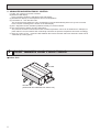
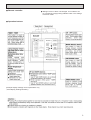
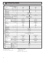
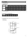
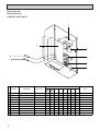
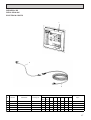
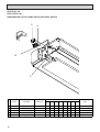
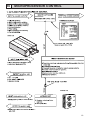
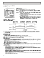
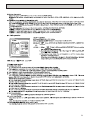
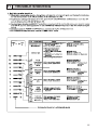
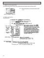
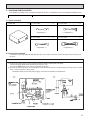
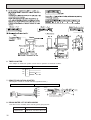
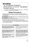
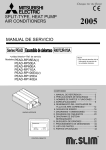
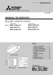
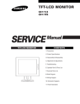
ADVANCE AND EVER ADVANCING
2000
SPLIT-TYPE, AIR CONDITIONERS
TECHNICAL & SERVICE MANUAL
This manual does not cover the
following outdoor units. When
servicing them, please refer to
the service manual No.OC149B
and this manual as a set.
PU-2VJA2.UK
PU-2.5VJA2.UK
<indoor unit> Service ref.
Models
PED-2EJA1.UK
PED-2.5EJA1.UK
CONTENTS
INDOOR UNIT
1. FEATURES ················································· 1
2. PART NAMES AND FUNCTIONS ·············· 2
3. SPECIFICATIONS ······································ 4
4. DATA ··························································· 5
5. REFRIGERANT SYSTEM DIAGRAM ······· 8
6. OUTLINES AND DIMENSIONS ················· 9
7. WIRING DIAGRAM ···································· 10
8. DISASSEMBLY INSTRUCTIONS ············· 11
9. PARTS LIST ·············································· 14
10. MICROPROCESSOR CONTROL·············· 19
11. TROUBLE SHOOTING ······························ 25
12. OPTIONAL PARTS ···································· 27
The Slim Line.
From Mitsubishi Electric
TM
REMOTE CONTROLLER
1 FEATURES
lndoor unit
Remote controller
Models
Cooling capacity (240V)
W
Btu/h
18,800
5,500
22,200
6,500
PED-2EJA1.UK
PED-2.5EJA1.UK
1. TOTALLY INVISIBLE INDOOR UNIT BEHIND THE CEILING
The totally hidden indoor unit that lies above the ceiling surface enables you to utilize full floor space while allowing for
flexible interior design. This new feature is recommended for stores and offices where the user's own imagination is
allowed to be incorporated.
2. MOST SUITABLE FOR SIMULTANEOUS TWO ROOM AIR CONDITIONING
Using air ducts for cooling airflow that matches the structure and purpose of the room, enables you to provide two air
outlets for simultaneous cooling of two rooms.
Air outlet duct
air outlet
air outlet
Air intake duct
air intake
3. HIGH EXTERNAL STATIC PRESSURE
The exceptional external static pressure of 70Pa allows long ducts to be used more extensively to achieve convenient
location of indoor units. (The factory setting is 30Pa.)
4. DRAIN WATER LIFT-UP MECHANISM (OPTION KIT)
This allows more versatility when selecting drain piping layouts.
1
5. ADVANCED MICROPROCESSOR CONTROL
(1) Ultra - thin 12mm(1/2" )remote controller.
(2) Attractive LED display .
Every operation condition is indicated on the LED display.
(3) Simultaneous display of set temperature and room temperature.
(4) Convenient 12 - hour ON-OFF timer.
This convenient timer allows the unit to be switched on and off automatically,at the time you set. Once the
timer is set,the remaining time is shown on the LED display..
(5) Self - diagnostic function indicates problems instantly on remote controller.
(6) The useful memory feature can store instructions.
The previous set value is memorized so that constant temperature control can be obtained. For example,if a
power failure occurs, this feature will conveniently memorize the previous temperature and reset accordingly.
(7) There is a polar 12 core - conductor cable between the remote controller and indoor board.The cable can be
extended up to 50m.(option)
2 PART NAMES AND FUNCTIONS
● Indoor Unit
Air outlet
or
Air intake
(sucks the air from inside the room into the unit)
2
● Remote controller
● Settings remain in effect until changed. Air conditioner can
be operated by simply pushing ON/OFF button once settings
have been made.
● Operation buttons
(Example display readings are for explanations only
;actual display readings will differ.)
3
3
SPECIFICATION
Model
Item
Cooling capacity
✻4
OUTDOOR UNIT
INDOOR UNIT
Total input
✻4
Power supply
Input
Running current
Starting current
External finish
Heat exchanger
Fan (drive) ~No.
Fan motor output
✻1
Airflow (Low-High)
External static pressure
✻2
Operation control & Thermostat
Noise level (Low-High) ✻ 3, ✻5
Cond. drain conn. O.D.
W
Dimensions
D
H
Weight
Model name
Power supply
Input
Running current
Starting current
External finish
Refrigerant control
Compressor
Model
Motor output
Starter type
Btu/h
W
kW
18,800
5,500
2.63
22,200
6,500
2.69
kW
A
A
0.15
0.63
1.1
~/N, 50Hz, 220-240V
Weight
Refrigerant
Charge
Pipe size O.D.
Connection method
Between the indoor
& outdoor unit
0.17
0.72
1.6
Galvanized sheets
Plate fin coil
Centrifugal (direct)x2
kW
CMM,(CFM)
Pa(mmAq)
0.076
13.5- 17(476-600)
dB (A)
mm, (in)
mm, (in)
mm, (in)
mm, (in)
kg, (lbs)
36-40
0.116
17-21 (600-740)
30(3)/70(7) at Hi-notch
Remote control&Built-in
37-41
32(1-1/4)
935(36-13/16)
700(27-9/16)
295(11-5/8)
33(73)
PU-2VJA.UK
~/N
50Hz
220-240V
2.48
10.8
52
1175(46-1/8)
700(27-9/16)
295(11-5/8)
42(93)
PU-2.5VJA.UK
~/N
50Hz
220-240V
2.52
10.7
52
Munsell 5Y 7/1
Capillary tube
Hermetic
NHJ41VMDT
1.9
Line Start
kW
Protection devices
Dimensions
REFRIGERANT
PIPING
PED-2.5EJA1.UK
kW
A
A
Inner thermostat,HP switch,LP switch
Plate fin coil
Heat exchanger
Fan (drive) ~No.
Fan motor output
Airflow
Noise level
W
D
H
kW
CMM,(CFM)
dB (A)
mm, (in)
mm, (in)
mm, (in)
kg, (lbs)
Propeller(direct)X1
0.085
50(1765)
52
870(34-1/4)
295+24(11-5/8 add 1)
850(33-7/16)
71(157)
Propeller(direct)X1
0.065
45(1588)
49
870(34-1/4)
295+24(11-5/8 add 1)
650(25-5/8)
60(132)
R-22
kg, (lbs)
mm, (in)
mm, (in)
1.78(3.92)
2.4(5.29)
9.52(3/8)
15.88(5/8)
Flared
Flared
30
30
Liquid
Gas
Indoor side
Outdoor side
Height difference (m)
Piping length (m)
✻ 1. External static pressure at 70Pa.
✻ 2. Ex-works at 30Pa.
✻ 3. External static pressure at 30Pa.
4
PED-2EJA1.UK
✻ 4.Rating condition <JIS B 8615>
INDOOR : 27 ˚CDB, 19 ˚CWB
OUTDOOR : 35 ˚CDB
✻ 5.Noise level : Sound pressure level
4
DATA
1. PERFORMANCE DATA
1) COOLING CAPACITY
Service Ref.
PED2EJA1.UK
PED2.5EJA1.UK
Indoor
intake air
WB˚C
16
18
20
22
16
18
20
22
20
CA
5,599
5,957
6,320
6,688
6,617
7,039
7,468
7,904
Outdoor intake air DB˚C
30
35
CA
P.C.
CA
P.C.
2.54
4,989
2.38
5,225
2.61
5,324
2.44
5,566
2.66
5,676
2.49
5,929
2.72
6,050
2.54
6,309
2.60
5,896
2.43
6,175
2.66
6,292
2.49
6,578
2.72
6,708
2.54
7,007
2.79
7,150
2.60
7,456
25
P.C.
2.13
2.17
2.21
2.25
2.18
2.22
2.26
2.30
CA
5,445
5,803
6,171
6,562
6,435
6,858
7,355
7,754
P.C.
2.22
2.27
2.30
2.35
2.27
2.32
2.36
2.40
40
CA
4,741
5,071
5,418
5,786
5,603
5,993
6,403
6,838
P.C.
2.70
2.77
2.84
2.92
2.76
2.83
2.90
2.98
45
CA
4,488
4,813
5,154
5,511
5,304
5,688
6,091
6,513
P.C.
2.15
2.30
2.47
2.63
2.20
2.36
2.52
2.70
Note C A: Capacity(W)
P.C.: Power consumption(kW)
2) COOLING CAPACITY CORRECTION FACTORS
Service Ref.
PED- 2EJA1.UK
PED- 2.5EJA1.UK
5m
1.00
1.00
Refrigerant piping length(one way)
10m
15m
20m
25m
0.985
0.975
0.964
0.954
0.983
0.972
0.961
0.951
30m
0.944
0.940
2. PERFORMANCE CURVE (CAPACITY RATIO & TOTAL INPUT RATIO)
PED-2EJA1.UK
PED-2.5EJA1.UK
Cooling
CAPACITY(RATIO)
1.4
1.2
INDOOR WB (˚C)
22
20
18
16
1
0.8
0.6
1.4
INDOOR WB (˚C)
22
20
18
16
TOTAL INPUT(RATIO)
1.2
1
0.8
0.6
0.4
-5
5
15
25
35
46
OUTDOOR DB (˚C)
5
3. FAN PERFORMANCE AND CORRECTED AIR FLOW
PED-2EJA1.UK
Fan Performance <30Pa>
Corrected Air Flow
120
Correction factor
100
80
60
40
20
6
160
External static pressure (Pa)
(1Pa 0.1mmAg)
1.1
8
1.0
0.9
0.8
10
10 12 14 16 18 20
Air Flow (CMM)
Fan Performance <70Pa>
12 14 16 18
Air flow (CMM)
20
22
12 14 16 18
Air flow (CMM)
20
22
Heating
1.3
140
120
100
80
60
40
1.2
1.1
1.0
0.9
0.8
8
10
20
8
Capacity
input
Cooling
8
Correction factor
External static pressure (Pa)
(1Pa 0.1mmAg)
140
10 12 14 16 18 20 22
Air Flow (CMM)
Fan Performance <30Pa>
120
100
Corrected Air Flow
Correction factor
External static pressure (Pa)
(1Pa 0.1mmAg)
PED-2.5EJA1.UK
80
60
40
20
8
1.1
Capacity
input
Cooling
1.0
0.9
0.8
12 14 16 18 20 22
Air flow (CMM)
24 26
10 12 14 16 18 20 22 24
Air Flow (CMM)
Heating
120
100
80
60
40
20
10 12 14 16 18 20 22 24 26
Air Flow (CMM)
6
1.3
Correction factor
External static pressure (Pa)
(1Pa 0.1mmAg)
140
Fan Performance <70Pa>
1.2
1.1
1.0
0.9
0.8
12 14 16 18 20 22 24
Air flow (CMM)
26
4. ELECTRICAL DATA
Indoor ······220V 50Hz 1phase
Outdoor ··· 220V 50Hz 1phase
Indoor
PED-2EJA1.UK
PED-2.5EJA1.UK
Outdoor
PU-2VJA
PU-2.5VJA
Capacity(W)
5,400
6,300
Total input(kW)
2.57
2.61
Input(kW)
0.13
0.15
Current(A)
0.60
0.69
Starting current(A)
1.05
1.53
Input(kW)
2.44
2.46
Current(A)
11.3
11.4
48
48
Indoor
PED-2EJA1.UK
PED-2.5EJA1.UK
Outdoor
PU-2VJA
PU-2.5VJA
Capacity(W)
5,450
6,400
Total input(kW)
2.60
2.65
Input(kW)
0.14
0.16
Current(A)
0.61
0.70
Starting current(A)
1.07
1.56
Input(kW)
2.46
2.49
Current(A)
11.0
11.0
50
50
Indoor
PED-2EJA1.UK
PED-2.5EJA1.UK
Outdoor
PU-2VJA
PU-2.5VJA
Capacity(W)
5,500
6,500
Total input(kW)
2.63
2.69
Input(kW)
0.15
0.17
Current(A)
0.63
0.72
Starting current(A)
1.10
1.60
Input(kW)
2.48
2.52
Current(A)
10.8
10.7
52
52
Outdoor
Indoor
Models
Starting current(A)
Indoor ······230V 50Hz 1phase
Outdoor··· 230V 50Hz 1phase
Outdoor
Indoor
Models
Starting current(A)
Indoor·······240V 50Hz 1phase
Outdoor··· 240V 50Hz 1phase
Outdoor
Indoor
Models
Starting current(A)
7
5. STANDARD OPERATION DATA (COOLING)
Total
Models
W
5,500
6,500
Input
kW
2.63
2.69
PED-2EJA
PED-2.5EJA
1, 50
1, 50
Refrigerant circuit
Electrical circuit
Phase Hz
Outdoor Indoor side
side
PED-2.5EJA1.UK
Capacity
Indoor unit model
5
PED-2EJA1.UK
Volts
240
240
Amperes
0.63
0.72
PU-2VJA
PU-2.5VJA
1, 50
1, 50
Outdoor unit-model
Phase,Hz
Volts
240
240
Amperes
10.8
10.7
Discharge pressure
MPa
1.98
2.00
Suction pressure
MPa
0.46
0.51
Discharge temperature
˚C
77.3
78.6
Condensing temperature
˚C
52.5
53.1
Suction temperature
˚C
15.3
8.5
Ref.Pipe length
m
5
5
DB˚C
27.0
27.0
WB˚C
19.0
19.0
DB˚C
14.8
16.0
DB˚C
35.0
35.0
WB˚C
24.0
24.0
SHF
0.74
0.71
BF
0.32
0.27
Intake air temperature
Diischarge air temperature
Intake air temperature
REFRIGERANT SYSTEM DIAGRAM
PED-2EJA1.UK
PED-2.5EJA1.UK
Indoor unit
Refrigerant pipe
(option)
15.88mm(5/8)
(With heat insulator)
Flexible tube
Thermistor
RT2
Flared
connection
Distributor
Strainer
Refrigerant pipe
(option)
9.52mm(3/8)
(With heat insulator)
8
6
OUTLINES & DIMENSIONS
1. INDOOR UNIT
PED-2EJA1.UK
PED-2.5EJA1.UK
55
Access door
8
B
81
197
355
Lifting bolt hole
(14✕22)
18
56
Refrigerant piping flare connection (liquid ø9.52 copper tube):HP
Refrigerant piping flare connection (gas ø15.88 copper tube):LP
Drain R1(External thread)
Electrical parts box
Electric Heater···Only PEHD-EKHA Type
Drain Pump (Option)
Set
Drain Pipe (Option)···Use VP25(O.D.ø32 PVC TUBE)
Filter
365~465
2
3
4
5
6
7
C
159
1
81
10
C
D
E
830 804
290 1070 1044
10-ø3 (1.6, 2HP)
12-ø3 (2.5HP)
A
29
81
C
B
81
10
A
B
772 305
1012 280
50~150
450
Model
PED-2
PED-2.5
Service space:500 or more
450
A
282
288
256
176
Air inlet
E
13
D
30
10
163
7
Air outlet
277
45 80
85
227
2
40
3.5
21
In case of rear inlet
61
1
24
5
35
4
10
13
44 75
30
179
640
109
30
10-ø3 (1.6, 2HP)
12-ø3 (2.5HP)
10-ø3 (1.6, 2HP)
12-ø3 (2.5HP)
6
15
40
176
256
3
10
30
3.5
10
8
In case of bottom inlet
Air inlet
81
C
B
81
A
Keep duct-work length 850mm or more.
Be sure to apply the air filter (field supply) near the air inlet grille.
2. REMOTE CONTROLLER
9
7
WIRING DIAGRAM
MODELS:PED-2,2.5EJA1 WIRING DIAGRAM
I.B
4321
SW1
OFF
ON
321
SW3
OFF
ON
CN51
CN31
CND MULTIPLE HEATER
POWER
CN30
CN120
ZNR OUTDOOR
TO RC
OFF
ON
321
X6 X5
CNT
TRANS
DS
2
DP
RED
25 3 41 6
3 1
GRN/YLW
1
1 3 7
BLK
BLU
WHT
BRN
YLW
3
GRN/YLW
WHT
31
BRN
WHT
BRN
AC10.6V
RED
1
T
ORN
RED
GRY
GRY
BLK
BLK
432 1
AC14.5V
5 43 2 1
21
BLU
21
2 5 34 1 6
:OPTION PARTS
TRANSMISSION WIRES
12VDC 12CORE CONNECTOR
F2 1 2 3
F1
FAN1
CN4T
TRANS
CN20
CN50
INTAKE DRAIN
YLW
CN21
PIPE
BLU
RED
SW2
ORN
YLW
3 TB2
2
1
RED
BLU
L TB1
N
TO OUTDOOR UNIT
CONNECTING WIRES
12VDC(non-polar)
BREAKER
GRN/YLW
WHITE
PE
TO DUCT
R.B
LD8 LD7 CNR120
MF
RT2
RT1
External static
pressure 70Pa
C
External static
pressure 30Pa
NOTES
*
1.Since the indoor transfomer(T) is connected with 240V power.
if 220,230V
power is used, Change the wiring connection shown at fig: 1
240 YELLOW
fig: *1 When power supply is
230 ORANGE
230V
220 RED
220V
SYMBOL EXPLANATION(*·····Option parts)
SYMBOL
SYMBOL
NAME
LD11<R.B>
C
Capacitor (fan motor)
LD12<R.B>
Connector (remote controller)
CN120<I.B>
CN51<I.B>
Connector (centrally control)
LD13-24<R.B>
CNR120<R.B> Connector (remote controller)
MF
F1, 2<I.B>
Fuse <6.3A>
I.B
Indoor controller board
SW1(I.B)
LD1<R.B>
SW2(I.B)
Run indicator LED
LD3<R.B>
SW3(I.B)
Cooling indicator LED
LD4<R.B>
SW1(R.B)
Fan mode indicator LED
LD5<R.B>
SW2(R.B)
Fan high indicator LED
LD7<R.B>
Indicator mode temperature LED
SW3(R.B)
Indicator mode timer LED
LD8<R.B>
SW5(R.B)
LD9<R.B>
Dry indicator LED
R.B
LD10<R.B>
Fan low indicator LED
T
NAME
Off timer indicator LED
On timer indicator LED
Temperature/Timer remaining
time indicator LED
Indoor Fan motor
Function switch
Unit switch
Emergency operation switch
ON/OFF switch
Operation mode switch
Fan hige/low switch
Indicator switch
Remote controller board
Transformer
NOTES
1. Since the outdoor side electric wiring may change be sure
to check the outdoor unit electric wiring for servicing.
2. Symbols used in circuit diagram above are, :Terminal block,
:connector.
3. Emergency operation
If a trouble occurs with either the remote controller or
the indoor microcomputer and no other trouble exists,emergency operation for cooling can be performed by changing
the setting of dip switch (SW3<I.B>) on the indoor controller
board (emergency dry operation is not possible).
10
POWER SUPPLY
~(1phase)
220-240VAC 50Hz
SYMBOL
SW6(R.B)
SW7(R.B)
SW8(R.B)
TB1
TB2
RT1
RT2
X5,X6(I.B)
ZNR<I.B>
CNP
CN50
* DP
* DS
LD13
LD14
LD15
LD16
LD17
LD18
LD19
LD20
LD21
LD22
LD23
LD24
SW1
LD1
SW5 LD3
LD9
LD4
LD5
SW6
LD10
SW7
LD11
LD12
SW2
SW3
SW8
NAME
Temperature and timer setting up switch
Temperature and timer setting down switch
Timer continuous ON/OFF switch
Terminal block (power)
Terminal block (indoor/outdoor connecting line)
Thermistor (room temperature sensor
0˚C/15kΩ, 25˚C/5.4kΩ)
Thermistor (pipe temperature sensor
0˚C/15kΩ, 25˚C/5.4kΩ)
Auxiliary relay (fan motor)
Varistor
Drain pump connector
Drain sensor connector
Drain pump
Drain sensor
<Check items>
(1) Make sure that no other trouble exists with the outdoor unit.
Trouble with the outdoor unit prevents emergency operation.
(If any trouble exists with the outdoor unit,the trouble
location will be displayed on the remote controller and
the trouble position will be shown on the outdoor controller board LED.See electric circuit diagram of the outdoor
unit for details.)
(2) Make sure that there is no trouble with the indoor fan.
Emergency operation will be a continuous run with the power
ON/OFF(ON/OFFwith the remote controller is not possible).
<Emergency operation procedure>
(1) Set the dip switch(SW3<I.B>)on the indoor controller board
to 1 - 2 on and 3 off for cooling.
(2) Turn on the outdoor unit side circuit breaker.
(3) During emergency operation indoor fan runs at High speed.
(4) Thermostat will not function.Cold air blows out for defrosting during heating thus do not operate de frosting for
a long time.
(5) Emergency cooling should be limited to 10 hours maximum(the
indoor unit heat exchanger may freeze).
8
DISASSEMBLY INSTRUCTIONS
Figure1.
Disconnect the fan motor connecter
(and the booster heater connector)
Drain pan
catches (Hidden)
1
Heat exchanger
2
Bottom plate
assembly
Filter
Drain pan
catches (Hidden)
Bottom plate A
1. Removing the fan motor
1. Removing the 9 screws that fix the bottom plate A, and
remove it.
2. Removing the drain pan as follows:
(1) Remove the screw that fixes the drain pan.
(2) Slide the drain pan in the direction 1, Figure1 and
unhook the drain pan catch near the drain pipe.
(3) Slide the drain pan in the direction 2, Figure1 and
unhook the 2 catches on the other side of the drain
pipe.
3. Remove the 8 screws that fix the bottom plate assembly,
and remove it.
4. Disconnect the fan motor connector from the controller
box.
Drain pan
5. Remove the fan plate as follow:
Figure2.
1
Fan base
1
(1)Remove the 4 screws1
(2)Slide down the fan plate to remove.
6. Remove the sirocco fan setting screw and the
motor fixture setting screw to remove the motor
fixture.
Remove the other motor fixture as well, and then
remove the fan motor.
11
Figure3.
Fan base
Sirocco fan
Motor
Housing
assembly
Bush
Piece
Leg
Bush
Sirocco fan
Piece
12
Housing assembly
Figure4.
Drain socket
Pump cover
assembly
Drain pan cover
Drain pump
assembly
Drain hose
1
2
Rubber plug
Drain pan
2. Removing the drain water lift-up pump
1. Remove the drain pan. (Refer 1- 2.)
2. Disconnect the drain pump connector and drain sensor connector from the
controller box.
3. Remove the two screws of the pump cover assembly.
4. Remove the drain hose from drain socket.
5. Remove the three screws of the drain pump assembly.
6. Remove the earth screw and four nuts of the drain pump assembly.
7. Remove the drain pump from drain pump assembly.
13
9
PARTS LIST
PED-2EJA1.UK
PED-2.5EJA1.UK
EXTERNAL PARTS
5, 6
3, 4
9, 10
7, 8
1.2
Qt’y/set
No.
Part No.
Part Name
Drawing No.
PED-
PED-
2EJA1 2.5EJA1
1
S70 031 669 Bottom plate 1
W638939Z03
2
S70 011 669 Bottom plate 1
W638917Z03
3
S70 081 669 Bottom plate 2 ass’y
W638940G02
4
S70 091 669 Bottom plate 2 ass’y
W638918G02
5
S70 020 480 H.EX.General ass’y
W268511G02
6
S70 021 480 H.EX.General ass’y
W268511G03
7
S70 011 529 Drain pan ass’y
W638942G01
8
S70 021 529 Drain pan ass’y
W638920G01
9
S70 021 500 Filter
W638181G01
10 S70 031 500 Filter
W638181G02
11
14
1
1
1
1
1
1
1
1
1
1
Spec.
PED-2EJA1.UK
PED-2.5EJA1.UK
BLOWER PARTS
2, 3
5, 6
9, 10
7, 8
11
4
4
1
5, 6
1
7, 8
Qt'y/set
No.
Part No.
Part Name
Drawing No.
PED-
PED-
2EJA1 2.5EJA1
1 S07 652 131 Attachment
W353715H01
2
2 S70 051 677 Fan base ass'y
W638932G02
1
3 S70 061 677 Fan base ass'y
W638905G02
1
4 S70 922 105 Bush
W818836H01
2
5 S70 A88 114 Sirocco fan
W122296G01
2
6 S70 A89 114 Sirocco fan
W122297G01
7 S70 989 110 Housing ass'y
W638949G03
8 S70 985 110 Housing ass'y
W638949G04
9 S70 Y58 220 Motor
P714316X02
10 S70 Y56 221 Motor
P714774X01
11 S70 652 130 Motor support
W241060H03
2
2
2
2
2
1
<MF>
1
1
<MF>
1
12
13
14
15
PED-2EJA1.UK
PED-2.5EJA1.UK
CONTROL BOX PARTS
4
3
7
6
2
5
1
7
Qt’y/set
No.
Part No.
Part Name
1 S70 918 717 Terminalbed
Drawing No.
P436109X01
PED-
Spec.
PED-
2EJA1 2.5EJA1
1
1
<TB2>
2 S70 979 717 Terminalbed
P436110X01
1
1
<TB1>
3 S70 010 310 Controller
BG00L760G22
1
1
<I.B.>
4 S70 11K 799
BG65T178H03
1
1
<T>
5 S70 010 202 Thermistor S
BG71V161H04
1
1
<RT1>
6 S70 020 202 Thermistor H
BG71V162H08
1
1
<RT2>
7 S70 010 292 Ferrite core
P419114X01
2
2
8
9
10
16
Transformer
PED-2EJA1.UK
PED-2.5EJA1.UK
ELECTRICAL PARTS
1
3
2
Qt’y/set
No.
Part No.
Part Name
Drawing No.
PED-
Spec.
PED-
2EJA1 2.5EJA1
1 S70 010 713 Remote controller
BC00C006G34
1
1
J controller
2 S70 A00 305 Remote controller cable BG00K507G02
1
1
10m
3 S70 010 304 Cable ( for board )
1
1
0.5m
BG78R190G10
4
5
17
PED-2EJA1.UK
PED-2.5EJA1.UK
DRAIN WATER LIFT-UP PUMP PARTS (OPTIONAL PARTS)
3
4
1.2
5
Qt’y/set
No.
Part No.
Part Name
Drawing No.
PED-
PED-
2EJA1 2.5EJA1
1
1
1 S70 11K 355 Drain pump-94
BG56J144G13
2 S70 010 533
DB26F111H03
4
4
3 S70 K01 523 Drain socket ass’y
BB00P145G17
1
1
4 S70 W28 266 Drain sensor ass’y
DE00H343G21
1
1
5 S70 E69 558 Rubber plug
P312040X01
1
1
18
Cushion
Spec.
10
MICROPROCESSOR CONTROL
19
l
20
l
21
l
l
after
22
23
24
11
TROUBLE SHOOTING
25
26
12
OPTIONAL PARTS
1. REFRIGERANT PIPES
Part No.
PAC-05FFS-E
PAC-07FFS-E
PAC-10FFS-E
PAC-15FFS-E
5m
7m
10m
15m
Pipe length
Pipe size OD
Liquid:/ø9.52 Gas:/ø15.88
Connection method
Indoor unit:Flared Outdoor unit:Flared
Note 1.How to connect refrigerant pipes.
Factory supplied optional piping contains refrigerant at above atmospheric pressure. As long as the
connection takes no more than 5 minutes, no air will enter, and there will be no need for air purging.
Remove the blind caps and make the connections within 5 minutes. After the connections for the indoor and
outdoor units are made, open the stop valve on the outdoor unit to allow refrigerant gas to flow.
If piping length exceeds 5m, an additional charge of refrigerant is needed.
Note 2.The following main parts are contained in the optional refrigerant piping kit.
Heat insulating cover, vinyl tapes, nipples, sleeve and flange(for wall hole), connecting cables.
2. REMOTE CONTROLLER EXTENSION CABLE
When installing the remote controller at a distance from the air conditioner, use the designated extension cable with
connector.
Part No.
Length
PAC-905EC
PAC-906EC
12m
PAC-918EC
20m
30m
PAC-919EC
50m
3. TIMER
When using a program timer, a program timer adapter (PAC-825AD)is also needed.
Part No.
Model Name
PAC-SK65PT(with set back function)
Program timer
3-1 Program timer specifications
Part name
Program timer
Part No.
PAC-SK65PT
Exterior dimensions(mm)
120X120X15 (mm)
Installation
Wall mount
Type of clock
Quartz
Clock accuracy
±50second/month
Display-Time
Liquid crystal display
-Week
Liquid crystal display
-Timer
Liquid crystal display
Program cycle
24 hours
Timer setting unit
30 minutes
No. of set points
48/day
Power rating
5V DC
Set back function
Provided
3-2 Feature of program timer
(1) Daily timer function
Daily timer can be set in 30 minute units for up to 24 hours.
Each unit can be set for unit ON, unit OFF, or setback operation.
(2) Setback operation(PAC-SK65PT)
Set back operation is useful for reducing running costs.
e.g.AT a hotel with a 24-hour system
8:00~23:00 Cooling operation with set temperature at 26 ˚C
23:00~8:00 Setback operation with 2 degrees of setback
As shown in the chart on the right, the set temperature rises 2
degrees automatically during the setback operation. When the setback operation ends, normal operation will begin.
(3) Weekly timer function
Daily timer function can apply to each day of the week.
28˚C
26˚C
8:00
Normai
operation
23:00
Setback
operation
8:00
Normai
operation
27
3-3 HOW to connect program timer
(1) Install the program timer next to the remote controller the same way as the remote controller is installed.
(2) Connect the program timer and the remote controller with a 6-wire cable as shown in the figure below.
NOTE: While the program timer is connected to the remote controller,
the 24 hour ON/OFF timer on the remote controller will not
operate.
3-4 Names and functions
<PAC-SK65PTA>
28
4. CENTRALIZED REMOTE CONTROLLER
Allows individual or combined control of up to 16 units.
Part No.
PAC-805RC
4-1 Dimensions
113
12
23.5
56.5
11
8
113
117
Unit:mm
117
4-2 Functions
"ENGAGED" indicator
When this indicator is lit, transmisson is in
progress and all swiches are inoperative.
DUAL / CENTRAL
switch
This change-over switch governs the operation of the accessory remote controller.
"DUAL"
Instructions
from
both
the
accessory
remote controller and the centralized
remote
controller
are
valid.
(Priority
given to the last instruction received.)
"CENTRAL"
ON / OFF switching by the accessory
remote controller is invalidate. Operation is
controlled by the centralized remote controller only.
Inital setting is "DUAL"
LCD Matrix display
This display indicates the operational status of all connected units either by steady
lighting or by flashing.
POWER ON / OFF
switch
Operation ON / OFF switch.
BACK
AHEAD buttons
These buttons are used to designate the
attached unit (s). (They designate the unit
to be centrally controlled.)
•When group "00" is designated ; collective ON/OFF instruction is sent to all
units.
•When group "01" - "16" is designated ;
ON/OFF instruction is sent only to
the designated units.
ACTIVE / BYPASS switch
This change-over switch is for the program timer.
(It selects the timer operation on the
program timer.)
Use "BYPASS" when a program timer is
not connected.
"ACTIVE"
The switch turns ON/OFF commands
given
from
the
program
timer
automatically.
"BYPASS"
ON/OFF Operation is controlled by the
centralized remote controller only. Initial
setting is "BYPASS".
Independent "DUAL / CENTRAL" and "ACTIVE / BYPASS" setting of all the groups is prossible. When the power supply to
the centralized remote controller is cut due to power failure, all settings will return to the original "DUAL" and "BYPASS".
29
4-3 Connection method
(1) Connection in the power supply cord.
1. Connect the power supply cord to the power supply terminal-block and fix in-place with a tie-wrap. Connect a single
phase 200V AC(220, 230, 240V)to AN .
As E is the GND terminal,be sure to ground the earth wire.
2. Connect the transmission line to the transmission terminal-block and fix it in-place with a tie-wrap. Use a ø1.6
(AWG14)or above two-wire cable for the transmission line.
CAUTION: Never connect the power supply cord to the transmission terminal-block.
TERMINAL-BLOCK
FOR TRANSMISSION
TERMINAL-BLOCK
OF POWER SUPPLY
Transmission
Tie-wrap
POWER
SUPPLY
TRANSFORMER
Fuse(5A)
Tie-wrap
Wiring has to be changed when
a 200,230 or 240V power is used.
(2) Connection method of centralized remote controller and power supply board.
1. Connect the centralized remote controller and power supply board with a non-polar, two-wire cable.
TO adaptor's
terminal-block
Power supply board box
Non-polar
two-wire cable
3. Be sure to set the maximum address number with the dipswitch
SW17 on the centralized remote controller.
2. Wiring diagram
Centralized
remote controller
30
TO adaptor's
terminal-block
Power supply
board
Dip swirch
SW17
5. PROGRAM TIMER ADAPTER
This adapter is needed when a program timer(PAC-815PT)or a centralised remote controller(PAC-805RC)is used.
Part No.
PAC-825AD
5-1 Parts included
1 ADAPTER ···································x1
2 3-core cable ·································· x1
Length:2m(6' 7")
2 4-core cable ·································· x1
Length:2m(6' 7" )
2 3-core cable ·································· x1
Length:2m(6' 7")
2 5-core cable ·································· x1
Length:2m(6' 7")
5-2 Connection method
Connection and wiring methods differ with the type of the indoor unit used. Confirm the type before carrying out
the work.
(1) Connections in the adapter box
1. Connect the power supply cord to the terminal-block and fix in-place with a tie-wrap.
Connect a single phase 200V AC(220, 230, 240V) to LN.
As ; is the GND terminal, be sure to ground the earth wire.
2. Connect the transmission line to the transmission terminal-block and fix it in-place with a tie-wrap, when a centralized remote controller is being used.
CAUTION: Never connect the power supply cord to the transmission terminal-block.
31
6. TIMER ADAPTER
This adapter is needed for system control and for operation via external contacts.
Part No.
PAC-SA89TA-E
ORN
1
BRN
2
RED
3
7. REMOTE INDICATION ADAPTER
This adapter is used for remote indication(operation/check.)
Part No.
BRN
RED
ORN
YRW
GRN JST
XHP3
PAC-559AD
BRN
<Wiring>
RED
CN51
ORN
connector(5P)
GRN
± 25
Applied model
32
PED-2EJA1.UK, PED-2.5EJA1.UK
X1
RL
X2
GL
X1
X2
insulation is needed.
Wiring at the actual
place
The maximum distance between
indoor board and relay is 10m.
This allows more versatility when selecting drain piping layouts.
PAC-SK001DM-F
ORANGE
RED
BROWN Electrical
Optional multiple
display adaptor
8. DRAIN WATER LIFT-UP MECHANISM
Part No.
GREEN
YELLOW
1
YRW
5
5
Power
supply
TM
HEAD OFFICE MITSUBISHI DENKI BLDG. MARUNOUCHI TOKYO100 TELEX J24532 CABLE MELCO TOKYO
MEE00K028
Issued in Nov. 2000
Printed in Japan
New publication, effective Nov. 2000
Specifications subject to change without notice.