1
MPLAB Starter Kit for
dsPIC® Digital Signal Controllers
User’s Guide
© 2008 Microchip Technology Inc.
DS51700A
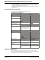
Note the following details of the code protection feature on Microchip devices:
•
Microchip products meet the specification contained in their particular Microchip Data Sheet.
•
Microchip believes that its family of products is one of the most secure families of its kind on the market today, when used in the
intended manner and under normal conditions.
•
There are dishonest and possibly illegal methods used to breach the code protection feature. All of these methods, to our
knowledge, require using the Microchip products in a manner outside the operating specifications contained in Microchip’s Data
Sheets. Most likely, the person doing so is engaged in theft of intellectual property.
•
Microchip is willing to work with the customer who is concerned about the integrity of their code.
•
Neither Microchip nor any other semiconductor manufacturer can guarantee the security of their code. Code protection does not
mean that we are guaranteeing the product as “unbreakable.”
Code protection is constantly evolving. We at Microchip are committed to continuously improving the code protection features of our
products. Attempts to break Microchip’s code protection feature may be a violation of the Digital Millennium Copyright Act. If such acts
allow unauthorized access to your software or other copyrighted work, you may have a right to sue for relief under that Act.
Information contained in this publication regarding device
applications and the like is provided only for your convenience
and may be superseded by updates. It is your responsibility to
ensure that your application meets with your specifications.
MICROCHIP MAKES NO REPRESENTATIONS OR
WARRANTIES OF ANY KIND WHETHER EXPRESS OR
IMPLIED, WRITTEN OR ORAL, STATUTORY OR
OTHERWISE, RELATED TO THE INFORMATION,
INCLUDING BUT NOT LIMITED TO ITS CONDITION,
QUALITY, PERFORMANCE, MERCHANTABILITY OR
FITNESS FOR PURPOSE. Microchip disclaims all liability
arising from this information and its use. Use of Microchip
devices in life support and/or safety applications is entirely at
the buyer’s risk, and the buyer agrees to defend, indemnify and
hold harmless Microchip from any and all damages, claims,
suits, or expenses resulting from such use. No licenses are
conveyed, implicitly or otherwise, under any Microchip
intellectual property rights.
Trademarks
The Microchip name and logo, the Microchip logo, Accuron,
dsPIC, KEELOQ, KEELOQ logo, MPLAB, PIC, PICmicro,
PICSTART, PRO MATE, rfPIC and SmartShunt are registered
trademarks of Microchip Technology Incorporated in the
U.S.A. and other countries.
AmpLab, FilterLab, Linear Active Thermistor, MXDEV,
MXLAB, SEEVAL, SmartSensor and The Embedded Control
Solutions Company are registered trademarks of Microchip
Technology Incorporated in the U.S.A.
Analog-for-the-Digital Age, Application Maestro, CodeGuard,
dsPICDEM, dsPICDEM.net, dsPICworks, dsSPEAK, ECAN,
ECONOMONITOR, FanSense, In-Circuit Serial
Programming, ICSP, ICEPIC, Mindi, MiWi, MPASM, MPLAB
Certified logo, MPLIB, MPLINK, mTouch, PICkit, PICDEM,
PICDEM.net, PICtail, PowerCal, PowerInfo, PowerMate,
PowerTool, REAL ICE, rfLAB, Select Mode, Total Endurance,
UNI/O, WiperLock and ZENA are trademarks of Microchip
Technology Incorporated in the U.S.A. and other countries.
SQTP is a service mark of Microchip Technology Incorporated
in the U.S.A.
All other trademarks mentioned herein are property of their
respective companies.
© 2008, Microchip Technology Incorporated, Printed in the
U.S.A., All Rights Reserved.
Printed on recycled paper.
Microchip received ISO/TS-16949:2002 certification for its worldwide
headquarters, design and wafer fabrication facilities in Chandler and
Tempe, Arizona; Gresham, Oregon and design centers in California
and India. The Company’s quality system processes and procedures
are for its PIC® MCUs and dsPIC® DSCs, KEELOQ® code hopping
devices, Serial EEPROMs, microperipherals, nonvolatile memory and
analog products. In addition, Microchip’s quality system for the design
and manufacture of development systems is ISO 9001:2000 certified.
DS51700A-page ii
© 2008 Microchip Technology Inc.
MPLAB STARTER KIT FOR
dsPIC® DIGITAL SIGNAL CONTROLLERS
USER’S GUIDE
Table of Contents
Preface ........................................................................................................................... 1
Chapter 1. Introduction
1.1 Overview ........................................................................................................ 7
1.2 Operational Requirements ............................................................................. 8
1.3 Board Setup ................................................................................................... 8
Chapter 2. Speech Record and Playback Demo
2.1 Running the Demo ......................................................................................... 9
2.2 Understanding the Demo ............................................................................. 10
2.3 Examining Demo Software Flow .................................................................. 11
Chapter 3. Develop an Application
3.1 Installing the Hardware and Software .......................................................... 15
3.2 Setting Up an Example Application for Debug ............................................. 16
3.3 Running the Example Application ................................................................ 17
3.4 Debugging the Example Application ............................................................ 17
3.5 Programming the Debugged Application ...................................................... 20
3.6 Creating Other dsPIC DSC Applications ...................................................... 20
3.7 Determining Device Support and Reserved Resources ............................... 20
3.8 Troubleshooting ............................................................................................ 21
3.9 Settings Dialog, Info Tab .............................................................................. 21
Chapter 4. Hardware
4.1 Audio Functional Overview ........................................................................... 23
4.2 Debug Functional Overview ......................................................................... 25
4.3 Board Components ...................................................................................... 26
Appendix A. Schematics
Figure A-1: Debug Input and Control Schematic – Part 1 .................................. 31
Figure A-2: Debug Input and Control Schematic – Part 2 .................................. 32
Figure A-3: USB Interface/Target Power Switching Schematic ......................... 32
Figure A-4: Speech Processing Schematic ........................................................ 33
Figure A-5: Flash Memory Schematics .............................................................. 33
Figure A-6: Output Compare Module PWM Filters Schematic ........................... 34
Figure A-7: Audio Codec Schematic .................................................................. 34
Figure A-8: Audio Input Schematic ..................................................................... 34
Figure A-9: Audio Output Schematic .................................................................. 35
Figure A-10: User LEDs, User Switches and Temp Sensor Schematics ........... 35
Index ............................................................................................................................. 37
Worldwide Sales and Service .................................................................................... 38
© 2008 Microchip Technology Inc.
DS51700A-page iii
MPLAB Starter Kit for dsPIC® DSCs User’s Guide
NOTES:
DS51700A-page iv
© 2008 Microchip Technology Inc.
MPLAB STARTER KIT FOR
dsPIC® DIGITAL SIGNAL CONTROLLERS
USER’S GUIDE
Preface
NOTICE TO CUSTOMERS
All documentation becomes dated, and this manual is no exception. Microchip tools and
documentation are constantly evolving to meet customer needs, so some actual dialogs
and/or tool descriptions may differ from those in this document. Please refer to our web site
(www.microchip.com) to obtain the latest documentation available.
Documents are identified with a “DS” number. This number is located on the bottom of each
page, in front of the page number. The numbering convention for the DS number is
“DSXXXXXA”, where “XXXXX” is the document number and “A” is the revision level of the
document.
For the most up-to-date information on development tools, see the MPLAB® IDE online help.
Select the Help menu, and then Topics to open a list of available online help files.
INTRODUCTION
This chapter contains general information that will be useful to know before you use the
MPLAB Starter Kit for dsPIC® Digital Signal Controllers. Items discussed in this chapter
include:
•
•
•
•
•
•
•
•
Document Layout
Conventions Used in this Guide
Warranty Registration
Recommended Reading
The Microchip Web Site
Development Systems Customer Change Notification Service
Customer Support
Document Revision History
DOCUMENT LAYOUT
This document describes how to use the starter kit as a development and demonstrative tool for dsPIC33F device’s speech and audio processing capabilities. The manual
layout is as follows:
• Chapter 1. Introduction – This chapter introduces the starter kit and provides an
overview of its features.
• Chapter 2. Speech Record and Playback Demo – This chapter describes a
simple program that demonstrates how to use the starter kit for speech capture
and playback.
• Chapter 3. Develop an Application – This chapter describes how to debug
application software on the starter kit using MPLAB® IDE.
© 2008 Microchip Technology Inc.
DS51700A-page 1
MPLAB Starter Kit for dsPIC® DSCs User’s Guide
• Chapter 4. Hardware – This chapter provides a functional overview of the starter
kit and identifies the major hardware components.
• Appendix A. Schematics – This appendix provides detailed schematic diagrams
of the starter kit.
CONVENTIONS USED IN THIS GUIDE
This manual uses the following documentation conventions:
DOCUMENTATION CONVENTIONS
Description
Arial font:
Italic characters
Initial caps
Quotes
Underlined, italic text with
right angle bracket
Bold characters
N‘Rnnnn
Text in angle brackets < >
Courier New font:
Plain Courier New
Represents
Examples
Referenced books
Emphasized text
A window
A dialog
A menu selection
A field name in a window or
dialog
A menu path
MPLAB® IDE User’s Guide
...is the only compiler...
the Output window
the Settings dialog
select Enable Programmer
“Save project before build”
A dialog button
A tab
A number in verilog format,
where N is the total number of
digits, R is the radix and n is a
digit.
A key on the keyboard
Click OK
Click the Power tab
4‘b0010, 2‘hF1
Italic Courier New
Sample source code
Filenames
File paths
Keywords
Command-line options
Bit values
Constants
A variable argument
Square brackets [ ]
Optional arguments
Curly brackets and pipe
character: { | }
Ellipses...
Choice of mutually exclusive
arguments; an OR selection
Replaces repeated text
Represents code supplied by
user
File>Save
Press <Enter>, <F1>
#define START
autoexec.bat
c:\mcc18\h
_asm, _endasm, static
-Opa+, -Opa0, 1
0xFF, ‘A’
file.o, where file can be
any valid filename
mcc18 [options] file
[options]
errorlevel {0|1}
var_name [, var_name...]
void main (void)
{ ...
}
WARRANTY REGISTRATION
Please complete the enclosed Warranty Registration Card and mail it promptly.
Sending in the Warranty Registration Card entitles you to receive new product updates.
Interim software releases are available at the Microchip web site.
DS51700A-page 2
© 2008 Microchip Technology Inc.
Preface
RECOMMENDED READING
This user's guide describes how to use the MPLAB Starter Kit for dsPIC Digital Signal
Controllers. Other useful documents are listed below. The following Microchip documents are available and recommended as supplemental reference resources.
Readme Files
For the latest information on using other tools, read the tool-specific Readme files in
the Readmes subdirectory of the MPLAB IDE installation directory. The Readme files
contain update information and known issues that may not be included in this user’s
guide.
dsPIC33F Family Reference Manual (DS70046)
Refer to this document for detailed information on dsPIC33F device operation. This
reference manual explains the operation of the dsPIC33F Digital Signal Controller
(DSC) family architecture and peripheral modules, but does not cover the specifics of
each device. Refer also to the appropriate device data sheet for device-specific
information and specifications.
dsPIC33F Family Data Sheet (DS70165)
This document provides an overview of the functionality of the dsPIC33F product
family. It includes device-specific information such as pinout diagrams, register maps,
electrical specifications and packaging, in addition to an overview of the CPU and
peripheral features.
dsPIC30F/33F Programmer’s Reference Manual (DS70157)
This manual is a software developer’s reference for the dsPIC30F and dsPIC33F 16-bit
DSC devices. It describes the instruction set in detail and also provides general
information to assist in developing software for the dsPIC30F/33F DSC family.
MPLAB® ASM30, MPLAB® LINK30 and Utilities User’s Guide (DS51317)
This document helps you use Microchip Technology’s language tools for dsPIC33F and
PIC24H devices based on GNU technology. The language tools discussed are the
MPLAB ASM30 Assembler, MPLAB LINK30 Linker, MPLAB LIB30 Archiver/Librarian
and other 16-bit device utilities.
MPLAB® C30 C Compiler User’s Guide and Libraries (DS51284)
This document helps you use Microchip’s MPLAB C30 C compiler to develop your
application. MPLAB C30 is a GNU-based language tool, based on source code from
the Free Software Foundation (FSF). For more information about FSF, see
www.fsf.org.
MPLAB® IDE User’s Guide (DS51519)
This document describes how to use the MPLAB IDE integrated development environment, as well as the MPLAB Project manager, MPLAB Editor and MPLAB SIM
simulator. Use these development tools to help you develop and debug application
code.
dsPIC® DSC Speech Coding Solutions User’s Guide (DS70295)
This document describes the dsPIC DSC Speech Encoding/Decoding Libraries including G.711, G.726A and Speex Speech Encoding/Decoding software application solutions. The individual libraries provide toll-quality voice compression and
decompression to help generate speech-based embedded applications on the
dsPIC30F and dsPIC33F families of digital signal controllers.
© 2008 Microchip Technology Inc.
DS51700A-page 3
MPLAB Starter Kit for dsPIC® DSCs User’s Guide
THE MICROCHIP WEB SITE
Microchip provides online support via our web site at www.microchip.com. This web
site is used as a means to make files and information easily available to customers.
Accessible by using your favorite Internet browser, the web site contains the following
information:
• Product Support – Data sheets and errata, application notes and sample
programs, design resources, user’s guides and hardware support documents,
latest software releases and archived software
• General Technical Support – Frequently Asked Questions (FAQs), technical
support requests, online discussion groups, Microchip consultant program
member listing
• Business of Microchip – Product selector and ordering guides, latest Microchip
press releases, listing of seminars and events, listings of Microchip sales offices,
distributors and factory representatives
DEVELOPMENT SYSTEMS CUSTOMER CHANGE NOTIFICATION SERVICE
Microchip’s customer notification service helps keep customers current on Microchip
products. Subscribers will receive e-mail notification whenever there are changes,
updates, revisions or errata related to a specified product family or development tool of
interest.
To register, access the Microchip web site at www.microchip.com, click on Customer
Change Notification and follow the registration instructions.
The Development Systems product group categories are:
• Compilers – The latest information on Microchip C compilers and other language
tools. These include the MPLAB C18 and MPLAB C30 C compilers; MPASM™
and MPLAB ASM30 assemblers; MPLINK™ and MPLAB LINK30 object linkers;
and MPLIB™ and MPLAB LIB30 object librarians.
• In-Circuit Emulators – The latest information on Microchip in-circuit emulators.
These include the MPLAB REAL ICE and MPLAB ICE 2000 in-circuit emulators.
• In-Circuit Debuggers – The latest information on Microchip in-circuit debuggers.
These include MPLAB ICD 2 and PICkit™ 2.
• MPLAB IDE – The latest information on Microchip MPLAB IDE, the Windows®
Integrated Development Environment for development systems tools. This list is
focused on the MPLAB IDE, MPLAB IDE Project Manager, MPLAB Editor and
MPLAB SIM simulator, as well as general editing and debugging features.
• Programmers – The latest information on Microchip programmers. These include
the MPLAB PM3 device programmer and the PICSTART® Plus and PICkit 1 and 2
development programmers.
DS51700A-page 4
© 2008 Microchip Technology Inc.
Preface
CUSTOMER SUPPORT
Users of Microchip products can receive assistance through several channels:
•
•
•
•
Distributor or Representative
Local Sales Office
Field Application Engineer (FAE)
Technical Support
Customers should contact their distributor, representative or field application engineer
(FAE) for support. Local sales offices are also available to help customers. A listing of
sales offices and locations is included in the back of this document.
Technical support is available through the web site at: http://support.microchip.com
DOCUMENT REVISION HISTORY
Revision A (February 2008)
• Initial Release of this Document
© 2008 Microchip Technology Inc.
DS51700A-page 5
MPLAB Starter Kit for dsPIC® DSCs User’s Guide
NOTES:
DS51700A-page 6
© 2008 Microchip Technology Inc.
MPLAB STARTER KIT FOR
dsPIC® DIGITAL SIGNAL CONTROLLERS
USER’S GUIDE
Chapter 1. Introduction
Thank you for purchasing Microchip Technology's MPLAB Starter Kit for dsPIC® Digital
Signal Controllers. This kit is intended to introduce and demonstrate the features of the
dsPIC33F Digital Signal Controllers (DSCs), and, in particular, some of the speech and
audio processing capabilities of dsPIC DSC devices. The starter kit demonstrates a
low-cost yet effective software technique for processing acceptable voice-quality audio.
Also, the board includes a 24-bit audio codec for high-quality audio applications. In
addition, the starter kit has on-board in-circuit debug circuitry so that you may develop
and debug your own application.
This chapter introduces the starter kit and provides an overview of its features. Topics
covered include:
• Overview
• Operational Requirements
• Board Setup
1.1
OVERVIEW
The MPLAB Starter Kit for dsPIC Digital Signal Controllers connects directly to the USB
port on a computer. The PC USB connection supplies communications and power to
the board.
The starter kit includes debug and programmer circuitry that allows applications to be
programmed onto the board’s dsPIC33F device and then debugged, all using MPLAB
IDE.
Audio input signals from an external microphone or audio equipment are routed to the
ADC module in the on-board dsPIC33F device for software processing. Alternatively,
applications can use the audio codec for converting the audio signal.
Output signals can be generated by the dsPIC33F device’s Output Compare module
as a Pulse-Width Modulated (PWM) digital waveform. This PWM signal is converted to
an analog signal by a low-pass filter on the starter kit board. Alternatively, applications
can output audio data using the audio codec. The output audio signal is then amplified
using a headphone amplifier circuit for playback on a headphone.
In addition to the Recommended Reading listed in the Preface, the following
manufacturers’ data sheets are also recommended as reference sources:
• National Semiconductor Corporation Data Sheet, LM4811 Boomer® Audio Power
Amplifier Series Dual 105mW Headphone Amplifier with Digital Volume Control
and Shutdown Mode (DS200061)
• Wolfson Microelectronics Data Sheet, WM8510 Mono CODEC with Speaker
Driver, Production Data December 2006, Rev. 4.1
© 2008 Microchip Technology Inc.
DS51700A-page 7
MPLAB Starter Kit for dsPIC® DSCs User’s Guide
1.2
OPERATIONAL REQUIREMENTS
To communicate with and program the MPLAB Starter Kit for dsPIC Digital Signal Controllers, the following hardware and software requirements must be met:
•
•
•
•
PC compatible system
An available USB port on PC or powered USB hub
CD-ROM drive
Windows® 2000 SP4, Windows XP SP2, and Windows Vista™ (32-Bit)*
Operating Systems
* Only initial testing has been performed on 32-bit Vista for this release. 64-bit
Vista is not supported at this time.
• Headphones (not included) – See Section 4.3.2.9 “Headphone Output Jack
(J8)” for requirements.
• Microphone (not included) – See Section 4.3.2.10 “Line/Microphone Input
Phone Jack (J9)” for requirements.
1.3
BOARD SETUP
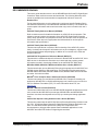
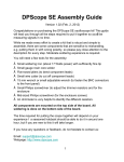
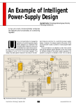
Figure 1-1 is a drawing of a set up MPLAB Starter Kit for dsPIC Digital Signal
Controllers. A microphone and headphone will need to be connected to the board (not
included). The USB connection provides communication and power to the board. The
demonstration software on the dsPIC33F device plays back speech stored on the
board’s serial Flash memory and allows recording and playback of recorded speech.
FIGURE 1-1:
MPLAB STARTER KIT FOR dsPIC® DIGITAL SIGNAL
CONTROLLERS SETUP
Headphone
(not included)
USB
Starter Kit
dsPIC33F
Microphone
(not included)
MPLAB® IDE
DS51700A-page 8
© 2008 Microchip Technology Inc.
MPLAB STARTER KIT FOR
dsPIC® DIGITAL SIGNAL CONTROLLERS
USER’S GUIDE
Chapter 2. Speech Record and Playback Demo
This chapter describes the Speech Record and Playback Demonstration application
that is preloaded on the dsPIC33F device. This application demonstrates how to use
the starter kit for speech capture, speech playback, speech encoding and decoding,
and using the serial Flash memory to store speech samples. Topics covered include:
•
•
•
•
2.1
Running the Demo
Understanding the Demo
Examining Demo Software Flow
Other Demo Code Examples
RUNNING THE DEMO
To run the demo, follow these basic steps:
1. Connect a microphone to socket J9. Connect a headphone to socket J8. Ensure
that potentiometer R56 is set to the factory setting, i.e., the arrow on the
potentiometer points to the arrow on the board.
2. Power up the starter kit by connecting the board to the USB port of a computer.
You should briefly see a pop-up balloon in the system tray (lower right of desktop)
that states (1) new hardware has been found, (2) drivers are being installed, and
(3) new hardware is ready for use. If you do not see these messages and then
the starter kit does not work, try reconnecting the USB. If this does not work, see
Section 3.8 “Troubleshooting”.
3. When powered up, the application will repeatedly play back an introductory
message.
To use the application, follow these steps:
1. To record speech, press switch S1 and wait till the Red LED turns off (the serial
Flash memory is being erased) and the Yellow LED turns on. The application will
now record the microphone audio signals and store them in the serial Flash
memory.
2. Press switch S2 to playback and listen to the stored speech samples. The Green
LED turns on during playback.
3. Pressing switch S1 again erases the serial Flash memory and prepares the
system for another recording.
© 2008 Microchip Technology Inc.
DS51700A-page 9
MPLAB Starter Kit for dsPIC® DSCs User’s Guide
2.2
UNDERSTANDING THE DEMO
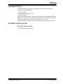
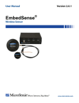
The dsPIC33F device on the starter kit is pre-programmed with a Speech Record and
Playback Demonstration application. The CD that accompanies the starter kit contains
the application code. As shown in Figure 2-1, this sample application uses the board to
capture an input microphone signal using the audio codec. The application program
running on the device does the following:
• Reads an introductory speech message stored on the serial Flash memory and
uses the audio codec to play back the audio signal.
• If speech recording is desired, the application compresses the incoming digital
signal from 16 bits to 8 bits using the G.711 μ-law encoding algorithm and stores
the encoded speech samples on the serial flash memory.
• If playback is desired, the application reads the serial Flash memory device and
decodes the read samples using the G.711 μ-law decoding algorithm. The
application then uses the audio codec to play back the speech signal.
FIGURE 2-1:
SPEECH RECORD AND PLAYBACK DEMO OVERVIEW
STARTER KIT BOARD
dsPIC33F
Data
G.711
μ-LAW
ENCODE
DCI
AUDIO
CODEC
Control
G.711
μ-LAW
DECODE
2
I C™
SPI
Serial Flash Memory
The board also features circuitry for audio playback using the Pulse-Width Modulation
technique. This technique can be used to implement a low-cost audio playback system.
For a demo of this technique, access the starter kit’s CD-ROM.
The demo program consists of three basic software elements: WM8510 Codec Driver,
G.711 Speech Encoder and Decoder, and Serial Flash Memory Driver.
2.2.1
WM8510 Codec Driver
The WM8510 Codec Driver configures the WM8510 audio codec and provides an interface for reading and writing audio data to the codec. The driver is implemented in
WM8510CodecDrv.c and the interface is defined in WM8510CodecDrv.h. The driver
uses the DCI module on the dsPIC33F device module to process data and the I2C™
module as a codec control bus. The demo application configures the codec for a 8 KHz
sampling rate.
DS51700A-page 10
© 2008 Microchip Technology Inc.
Speech Record and Playback Demo
2.2.2
G.711 Speech Encoder and Decoder
The G.711 Encoder and Decoder implement the ITU-T G.711 Speech Compression
algorithm. This algorithm is an example of a waveform coder and provides a compression ratio of 2:1. The algorithm is implemented in G711.s and its interface is defined
by G711.h
2.2.3
Serial Flash Memory Driver
The Serial Flash Memory driver uses the SPI peripheral on the dsPIC33F device to
interface with the external serial Flash memory device. The driver requires a buffer for
its operation and this buffer must be allocated by the application. The driver allows the
application to perform operations such as read, chip erase, sector erase and status
check.
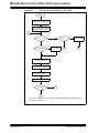
2.3
EXAMINING DEMO SOFTWARE FLOW
The Speech Record and Playback Demonstration application uses the WM8510
codec, G.711 speech encoding and decoding libraries, and the serial Flash memory
drivers to read, output and store speech signals with the starter kit. The application will
encode a microphone signal, store the encoded samples in serial flash memory and
play back the decoded samples to a headphone output. The G.711 μ-law algorithm is
used for encoding and decoding speech samples. Figure 2-2 and Figure 2-3 are flow
charts of the demo application.
© 2008 Microchip Technology Inc.
DS51700A-page 11
MPLAB Starter Kit for dsPIC® DSCs User’s Guide
FIGURE 2-2:
APPLICATION FLOW CHART – PART ONE
START
Initialize Audio Codec Driver
Initialize Flash Memory Driver
Start Audio Codec Driver
Start Flash Memory Driver
B*
No
No
Record = 1?
Playback = 1?
Yes
Play back
Intro Message
Yes
No
Is Flash Erased?
Erase Flash
Red LED On
A*
C*
Yes
Yellow LED On
Read Codec Data
G.711 μ-Law Encode
Store In Flash
Output Audio Data
No
Is Flash Full?
C*
Yes
A*
*Refer to the corresponding letter in Figure 2-3: “Application Flow Chart – Part Two” for the
continuation of the flow chart.
DS51700A-page 12
© 2008 Microchip Technology Inc.
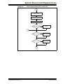
Speech Record and Playback Demo
FIGURE 2-3:
APPLICATION FLOW CHART – PART TWO
A
Read Serial Flash
Green LED On
G.711 μ-Law Decode
Output Audio Data to Codec
Yes
End of Message?
Rewind Playback
Pointer
No
C
Yes
Switch 1 Active?
Record = 1
Stop Playback
No
Yes
Switch 2 Active?
Playback = 1
Stop Record
No
B
© 2008 Microchip Technology Inc.
DS51700A-page 13
MPLAB Starter Kit for dsPIC® DSCs User’s Guide
2.4
OTHER DEMO CODE EXAMPLES
The starter kit software CD includes other demo code examples.
The SASK Record Play Demo with Intro Code Example demonstrates the low-cost
speech capture and playback option. It uses the dsPIC DSC 12-bit ADC to capture
speech samples. The data is stored in the serial Flash memory. The application then
uses the Output Compare module in Pulse-Width Modulation (PWM) mode to generate
a PWM signal representing the speech signal.
Note:
Jumper J6 should in the OCPWM position to use this demo.
The SASK Intro Speech Prog code example can be used to program the introductory
message into the serial Flash. This is useful in a case where the entire serial Flash has
been erased and it is desirable to set up the introductory message again.
Note:
DS51700A-page 14
The SASK Intro Speech Prog code example performs a full chip erase on
the serial Flash. In order to prevent accidental serial Flash chip erase when
the board is taken in and out of Reset, erase the dsPIC33F program Flash
via MPLAB IDE after the running the SASK Intro Speech Prog code
example. Refer to the readme.txt files in the project folder for more
details.
© 2008 Microchip Technology Inc.
MPLAB STARTER KIT FOR
dsPIC® DIGITAL SIGNAL CONTROLLERS
USER’S GUIDE
Chapter 3. Develop an Application
The MPLAB Starter Kit for dsPIC® Digital Signal Controllers may be used with MPLAB
IDE, the free integrated development environment available on Microchip’s website.
MPLAB IDE allows the starter kit to be used as an in-circuit debugger as well as a
programmer for the featured device.
In-circuit debugging allows you to run, examine and modify your program for the device
embedded in the starter kit hardware. This greatly assists you in debugging your
firmware and hardware together.
Special starter kit software interacts with the MPLAB IDE application to run, stop and
single-step through programs. Breakpoints can be set and the processor can be reset.
Once the processor is stopped, the register’s contents can be examined and modified.
For more information on how to use MPLAB IDE, reference the following
documentation:
• MPLAB® IDE User’s Guide (DS51519)
• MPLAB® IDE Quick Start Guide (DS51281)
• MPLAB® IDE On-line Help
This chapter includes the following:
•
•
•
•
•
•
•
•
•
3.1
Installing the Hardware and Software
Setting Up an Example Application for Debug
Running the Example Application
Debugging the Example Application
Programming the Debugged Application
Creating Other dsPIC DSC Applications
Determining Device Support and Reserved Resources
Troubleshooting
Settings Dialog, Info Tab
INSTALLING THE HARDWARE AND SOFTWARE
To install the hardware:
If you have not already set up the hardware to run the demo, follow these steps:
1. Connect a microphone to socket J9. Connect a headphone to socket J8. Ensure
that potentiometer R56 is set to the factory setting, i.e., the arrow on the
potentiometer points to the arrow on the board.
2. Power up the starter kit by connecting the board to the USB port of a computer.
You should briefly see a pop-up balloon in the system tray (lower right of desktop)
that states (1) new hardware has been found, (2) drivers are being installed, and
(3) new hardware is ready for use. If you do not see these messages and then
the starter kit does not work, try reconnecting the USB. If this does not work, see
Section 3.8 “Troubleshooting”.
3. When powered up, the application will repeatedly play back an introductory
message.
To install the software:
Run CD-ROM enclosed with the starter kit and install software as directed.
© 2008 Microchip Technology Inc.
DS51700A-page 15
MPLAB Starter Kit for dsPIC® DSCs User’s Guide
3.2
SETTING UP AN EXAMPLE APPLICATION FOR DEBUG
The MPLAB IDE software that is installed on your PC by the starter kit CD-ROM automatically opens an example application that you may use to examine debug features
of the starter kit.
To prepare the application for debug:
1. Launch MPLAB IDE. The example application project and related workspace will
open. For information on projects and workspaces, see the MPLAB IDE
documentation mentioned at the beginning of this chapter.
2. Select Project>Build All to build the application code. The build’s progress will be
visible in the Build tab of the Output window.
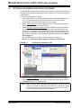
3. Select Debugger>Select Tool>Starter Kits. MPLAB IDE will change to add starter
kit debug features (Figure 3-1): (1) the status bar will show Starter Kits as the
debug tool, (2) a Starter Kit debug toolbar will be added, (3) the Debugger menu
will change to add Starter Kit debug functions and (4) the Output window will display communication status between MPLAB IDE and the stater kit on the Starter
Kit Debugger tab.
Also, several device resources are used for debug. For details, see
Section 3.7 “Determining Device Support and Reserved Resources”.
FIGURE 3-1:
STARTER KIT AS DEBUG TOOL
2
4
3
1
4. Select Debugger>Program to program the application code into the dsPIC33F
DCS device on the starter kit. The debug programming progress will be visible in
the Starter Kit tab of the Output window.
Note:
DS51700A-page 16
Debug executive code is automatically programmed in the upper program
memory of the starter kit device when the starter kit is selected as a debugger. Debug code must be programmed into the target device to use the
in-circuit debugging capabilities of the starter kit.
© 2008 Microchip Technology Inc.
Develop an Application
3.3
RUNNING THE EXAMPLE APPLICATION
The starter kit executes in either real-time (Run) or steps (Step Into, Step Over, Animate.) Real-time execution occurs when you select Run in MPLAB IDE. Once the
device code is halted, either by Halt or a breakpoint, you can step.
The following toolbar buttons can be used for quick access to commonly used debug
operations:
Debugger Menu
Toolbar Buttons
Run
Halt
Animate
Step Into
Step Over
Reset
To see how these options function, do the following:
1. Select Debugger>Reset>Processor Reset or click the Reset button to reset the
program.
2. Select Debugger>Run or click the Run button. Observe how the application
operates.
3. Select Debugger>Halt or click the Halt button to stop the program execution. A
green solid arrow will mark the line of code in the File window where the program
halted.
4. Select Debugger>Step Into or click the Step Into button to step the program execution once. The green solid arrow will move down one line of code in the File
window. Click the button several times to step through some code.
5. Select Debugger>Reset>Processor Reset click the Reset button to reset the
program again. The arrow will disappear, meaning the device is reset.
3.4
DEBUGGING THE EXAMPLE APPLICATION
For the example code given, everything works fine. However, when you are developing
code, it will likely not work the first time and need to be debugged. MPLAB IDE provides
an editor and several debug features such as breakpoints and Watch windows to aid
in application code debugging.
This section includes:
• Editing Application Code
• Using Breakpoints and Mouseovers
• Using Watch Windows
© 2008 Microchip Technology Inc.
DS51700A-page 17
MPLAB Starter Kit for dsPIC® DSCs User’s Guide
3.4.1
Editing Application Code
To view application code so it may be edited, do one of the following:
• Select Edit>New to create new code or Edit>Open to search for and open an
existing code file.
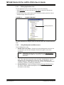
• Double click on a file in the Project window to open an existing code file. See an
example Project window in Figure 3-2.
FIGURE 3-2:
EXAMPLE PROJECT
Existing Code File
For more information on using the editor to create and edit code, see MPLAB Editor
Help.
3.4.2
Using Breakpoints and Mouseovers
To set a breakpoint in code:
1. Double Click in the Gutter – Double click in the window gutter next to the line
of code where you want the breakpoint. Double click again to remove the
breakpoint.
Note:
Double click must be set up for breakpoints. See Edit>Properities,
ASM/C/BAS File Type tab, checkbox for “Double-click Toggles
Breakpoint”.
2. Pop-up Menu – Place the cursor over the line of code where you want the breakpoint. Then, right click to pop up a menu and select “Set Breakpoint”. Once a
breakpoint is set, “Set Breakpoint” will become “Remove Breakpoint” and
“Disable breakpoint”. Other options on the pop-up menu under Breakpoints are
for deleting, enabling or disabling all breakpoints.
3. Breakpoint Dialog – Open the Breakpoint dialog (Debugger>Breakpoints) to
set, delete, enable or disable breakpoints. See MPLAB IDE Help for more
information on this dialog.
DS51700A-page 18
© 2008 Microchip Technology Inc.
Develop an Application
A breakpoint set in code will appear as a red hexagon with a “B” as shown in Figure 3-3.
FIGURE 3-3:
EXAMPLE BREAKPOINT
Once code is halted, hovering over variables pops up the current value of those
variables (see Figure 3-3.)
Note:
3.4.3
This feature must be set up. See Edit>Properties, Tooltips tab, check the
“Enable Variable Mouseover Values” checkbox.
Using Watch Windows
To use a Watch window:
1. The Watch window is made visible on the desktop by selecting View>Watch. It
contains four selectable Watch views (via tabs) in which to view variables (SFRs,
symbols and absolute addresses).
2. Select an SFR or Symbol from the list and click the related Add button to add it
to the Watch window. Or click in the “Address” column and enter an absolute
address.
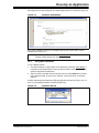
A Watch window populated with an SFRs and Symbols will look like Figure 3-4. For
more on using Watch windows, see MPLAB IDE Help.
FIGURE 3-4:
© 2008 Microchip Technology Inc.
EXAMPLE WATCH
DS51700A-page 19
MPLAB Starter Kit for dsPIC® DSCs User’s Guide
3.5
PROGRAMMING THE DEBUGGED APPLICATION
When the program is successfully debugged and running, the next step is to program
the device for stand-alone operation in the finished design. When doing this, the
resources reserved for debug are released for use by the application. To program the
application, use the following steps:
1. Disable Starter Kits as a debug tool by selecting Debugger>Select Tool>None.
2. Select Starter Kits as the programmer in the Programmer>Select Programmer
menu.
3. Select Programmer>Program.
Now the starter kit will run independently.
3.6
CREATING OTHER dsPIC DSC APPLICATIONS
This starter kit is just one way to use Microchip dsPIC DSCs in an application. Other
tools and resources exist to support these devices.
• dsPIC DSC Demo Boards – Many boards are available for developing applications. See our website (http://www.microchip.com/) under Design>Development
Tools>Demo Boards>dsPIC DSC.
• MPLAB C30 C Compiler, Full Version – More optimization options than the student version for full-scale development. See http://www.microchip.com/c30.
• Application Notes – Example applications with code for using dsPIC DSC features. See our website (http://www.microchip.com/) under Design>App Notes &
Source Code>16-bit PIC MCUs & dsPIC DSCs.
3.7
DETERMINING DEVICE SUPPORT AND RESERVED RESOURCES
Due to the built-in in-circuit debugging capability of ICD devices and the ICSP™
function offered by the debugger, the starter kit uses some on-chip resources when
debugging. It also uses program memory and file register locations in the target device
during debugging. These locations are not available for use by user code. In the
MPLAB IDE, registers marked with an “R” in register displays represent reserved
registers.
For information on device resources that are needed for in-circuit debugging, please
refer to the MPLAB ICD 2 Help, found in MPLAB IDE under Help>Topics. The device
reserved resource information found under “Resources Used By MPLAB ICD 2” is the
same for the starter kit.
DS51700A-page 20
© 2008 Microchip Technology Inc.
Develop an Application
3.8
TROUBLESHOOTING
Debug Connection Problems
While using the starter kit as a debugger, you may get the error “Unable to Enter Debug
Mode” when programming the device. This can result from communication being lost
between the starter kit and MPLAB IDE. To resolve this:
1. Unplug the USB cable from the starter kit.
2. Plug the USB cable back into the starter kit.
MPLAB IDE should automatically reconnect to the starter kit. If this does not work, do
the following:
1. Check the USB connection between the PC and starter kit at both ends.
2. If using a USB hub, make sure it is powered.
3. Make sure the USB port is not in use by another device.
Programming Problems
If during the course of developing your own application you can no longer program the
device on the starter kit, you may have set device configuration bits to code protect or
some other state that prevents programming. To view the settings of the configuration
bits, select Configure>Configuration Bits.
3.9
SETTINGS DIALOG, INFO TAB
When you select Debugger>Settings or Programmer Settings, you will open the Starter
Kit Settings dialog.
Currently, there is only one (Info) tab on this dialog, displaying the following
information:
• Firmware Version: The version of firmware on the starter kit board.
• Debug Exec Version: The version of the debug executive that is loaded into the
dsPIC33F device program memory to enable debug operation.
© 2008 Microchip Technology Inc.
DS51700A-page 21
MPLAB Starter Kit for dsPIC® DSCs User’s Guide
NOTES:
DS51700A-page 22
© 2008 Microchip Technology Inc.
MPLAB STARTER KIT FOR
dsPIC® DIGITAL SIGNAL CONTROLLERS
USER’S GUIDE
Chapter 4. Hardware
This chapter provides a functional overview of the MPLAB Starter Kit for dsPIC® Digital
Signal Controllers and identifies the major hardware components. Topics covered
include:
• Audio Functional Overview
• Debug Functional Overview
• Board Components
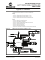
4.1
AUDIO FUNCTIONAL OVERVIEW
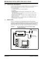
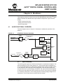
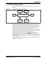
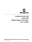
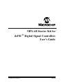
The block diagram shown in Figure 4-1 illustrates the mainstream operation of the
starter kit.
FIGURE 4-1:
STARTER KIT BLOCK DIAGRAM
LINE/MIC
SELECT
MICROPHONE
LINE/MICROPHONE
AMPLIFIER
J7
LINE INPUT
ANTIALIASING
LOW-PASS
FILTER
3 db to 23 db
TEMPERATURE
SENSOR
In
Out
AUDIO
CODEC
AN0
AN4
DCI
dsPIC33F
Device
I2C™
HEADPHONES
HEADPHONE
AMPLIFIER
SPI
J6
LOWPASS
FILTER
-33 db to 12 db
4.1.1
4 Mbit
FLASH
MEMORY
OUTPUT
SELECT
OC1
Speech Sampling
The incoming audio signal can come from a line input or a condenser microphone. The
speech sampling input is jumper selected (J7). The selected signal is amplified by a
non-inverting AC amplifier (Line/Microphone Amplifier) and routed to the ADC module
on the dsPIC33F device through an anti-aliasing filter. This sixth-order Sallen-Key
low-pass filter has a cut-off frequency of 3300 Hz. The output of the anti-aliasing filter
is connected to input AN0 of the ADC module on the device. If the input to the amplifier
is a condenser microphone, a bias voltage provides a working supply voltage for the
microphone. The line input does not require this bias voltage.
© 2008 Microchip Technology Inc.
DS51700A-page 23
MPLAB Starter Kit for dsPIC® DSCs User’s Guide
The amplifier has a variable gain from 3 db to 23 db, which can be adjusted to control
microphone sensitivity or boost a low line-input signal. The output of the amplifier is
biased at 1.65V.
4.1.2
Speech Playback
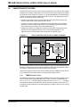
The mainstream speech playback interface processes the PWM digital signal from the
Output Compare module of the dsPIC33F device. A low-pass filter demodulates the
PWM signal as shown in Figure 4-2. The low-pass filter behaves like an integrator
whose output signal amplitude depends on the duty cycle of the input PWM waveform.
The PWM frequency should be an integral multiple of the audio sampling rate.
FIGURE 4-2:
PWM DEMODULATION
PWM SIGNAL FROM OCPWM
LOW-PASS FILTER
DEMODULATED AUDIO SIGNAL
R
C
The output of the low-pass filter feeds the headphone amplifier The headphone
amplifier drives an audio headphone. This amplifier can drive up to 75 mW into a 32
ohm headphone. The amplifier uses a digital volume control that is controlled by I/O
lines from the dsPIC33F device.
4.1.3
Codec
The audio codec can be used for a higher-end audio application. The input to the audio
codec is the output of the line/microphone pre-amplifier. The output feeds the
headphone amplifier. The codec must interact with the application program running on
the dsPIC33F device. Commands from the application program control the codec
operating parameters (such as communication protocol, sampling rate, volume control,
level control, filter settings, etc.). Command information is exchanged over the
Inter-Integrated Circuit™ (I2C™) module on the device.
The codec converts the incoming audio signal to a digital signal for the Digital
Converter Interface (DCI) module of the dsPIC33F device. Audio output from the
application program is sent to the codec via the DCI module. The codec converts this
digital signal to audio for the headphone amplifiers.
4.1.4
4 Mb Serial Flash Memory
The starter kit includes 4 Mb serial Flash memory that can be used for storing data. The
memory interfaces with the SPI bus on dsPIC33F device and might typically be used
by applications that require storage of speech samples for playback purposes.
DS51700A-page 24
© 2008 Microchip Technology Inc.
Hardware
4.2
DEBUG FUNCTIONAL OVERVIEW
The block diagram shown in illustrates the debugging/programming operation of the
starter kit.
STARTER KIT DEBUG BLOCK DIAGRAM
USB Mini-B
Jack
12 MHz
Crystal
3.3V LDO
Regulator
Status
LEDs
SPI
PIC18F67J50 Device
Serial EEPROM
25LC010A
ICSP™
FIGURE 4-3:
dsPIC33F
Device
The starter kit, with its built-in debugger/programmer, provides an all-in-one solution for
debugging and programming applications using MPLAB IDE. Also, no additional
external power supply is needed as power is supplied by the host PC’s USB port.
The starter kit's debugging/programming operations are controlled by a PIC18F67J50
MCU running at 48 MHz. The PIC18F67J50's built-in USB engine provides the
communications interface between the starter kit and the host PC.
Power to the starter kit is provided via USB whose nominal 5 volt unregulated supply
is regulated by a Microchip MC1727 3.3 volt low-dropout (LDO) linear regulator. Proper
starter kit main system power is indicated by the green LED ‘D1’.
The PIC18F67J50 MCU accomplishes debugging or programming of the target
dsPIC33FJ256GP506 by controlling the target’s MCLR, PGC1/EMUC1, and
PGD1/EMUD1 signals. Target power is switched on/off via a low VCE saturation PNP
transistor configured as a high-side switch. Target clocking is also provided by the
PIC18F67J50 MCU.
A Microchip 25LC010A serial EEPROM is used to store the starter kit’s serial number
and debug control information.
© 2008 Microchip Technology Inc.
DS51700A-page 25
MPLAB Starter Kit for dsPIC® DSCs User’s Guide
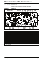
4.3
BOARD COMPONENTS
Figure 4-4 identifies the key starter kit hardware components.
FIGURE 4-4:
D2
STARTER KIT
D3
D4
A1
A2
A3
A4
A5
A6
A7
A8
A9
D1
D5
A10
M
D7
Ref
D6
A15
Component
A14 A13
Ref
A12
A11
Component
D1
Mini-B USB Connector (J1)
A5
D2
MCP1727 (U1)
A6
Output Select Jumper (J6)
Codec (U9)
D3
STATUS LED – Debug (D2)
A7
Headphone Amplifier (U11)
D4
STATUS LED – System Power (D1)
A8
Line/Microphone Input Select Jumper (J7)
Headphone Output Jack (J8)
D5
PIC18F67J50 MCU (U2)
A9
D6
Low Vce Saturation PNP Transistor Switch (Q1)
A10
Line/Microphone Input Phone Jack (J9)
D7
25LC010A Serial EEPROM (U3)
A11
User LEDs (D3,D4 and D5)
A1
Flash Memory (U5)
A12
Microphone Gain Control (R56)
A2
Digital Signal Control (U6)
A13
Line/Microphone Pre-Amplifier (U10:A)
A3
Temperature Sensor (U7)
A14
Anti-Aliasing Low-Pass Filter (U10:B,C,D)
A4
PWM Low Pass Filter (U8:A,B)
A15
User Switches (S2 and S1)
D# = Debug components
A# = Audio components
DS51700A-page 26
© 2008 Microchip Technology Inc.
Hardware
4.3.1
Debug Components
The following components support the debug function of the starter kit. See Appendix
A. “Schematics” for debug schematics.
4.3.1.1
MINI-B USB CONNECTOR (J1)
Provides system power and bidirectional communication between the host PC and
starter kit.
4.3.1.2
MCP1727 (U1)
3.3V Linear regulator. Regulates the USB unregulated voltage to 3.3 volts (with respect
to VSS) and supplies the starter kit with system power.
4.3.1.3
STATUS LED – DEBUG (D2)
When lit, indicates that communication between the starter kit and MPLAB IDE has
been successfully established.
4.3.1.4
STATUS LED – SYSTEM POWER (D1)
When lit, indicates that the starter kit is powered via the USB.
4.3.1.5
PIC18F67J50 MCU (U2)
Controls the programming/debugging operations of the target dsPIC33FJ256GP506
digital signal controller.
4.3.1.6
LOW Vce SATURATION PNP TRANSISTOR SWITCH (Q1)
Provides target power (via high-side switching) to the dsPIC33FJ256GP506 (and
ancillary circuitry) via control by the PIC18F67J50 programming/debugging MCU.
4.3.1.7
25LC010A SERIAL EEPROM (U3)
Provides nonvolatile parameter storage for the PIC18F67J50 MCU.
4.3.2
Audio Components
The following components support the audio portion of the starter kit. See Appendix
A. “Schematics” for audio schematics.
4.3.2.1
FLASH MEMORY (U5)
The starter kit includes a serial Flash memory chip (Ref A1). The power supply for U5
is provided by regulator U4. The regulator provides the required amount of current for
flash programming operation.
4.3.2.2
DIGITAL SIGNAL CONTROL (U6)
The dsPIC33F256GP506 digital signal controller (Ref A2) provides the computation
and processing resource for application development on the starter kit. This DSC
features 256 KB of program flash and 16 KB RAM. The application can either use the
on-chip FRC or the external 12 MHz signal as clock source.
4.3.2.3
TEMPERATURE SENSOR (U7)
The starter kit includes a temperature sensor (Ref A3) that interfaces to the ADC
module on the dsPIC33F device. The temperature sensor is a Microchip TC1047.
© 2008 Microchip Technology Inc.
DS51700A-page 27
MPLAB Starter Kit for dsPIC® DSCs User’s Guide
4.3.2.4
PWM LOW PASS FILTER (U8:A,B)
The PWM signal from the Output Compare module on the dsPIC33F device on the
board is demodulated by the PWM low-pass filter (Ref A4). This fourth-order filter uses
two op-amps (U8:A and U8:B) on the MCP6022 quad op-amp IC.
4.3.2.5
OUTPUT SELECT JUMPER (J6)
The Output Select Jumper (Ref A5) determines whether the input signal for the
Headphone Amplifiers comes from the PWM filter or the audio codec. Default setting
is CODEC.
4.3.2.6
CODEC (U9)
The starter kit includes an audio codec (Ref A6) that interfaces to the DCI module (data
interface) and I2C bus (control interface) of the dsPIC33F device. It is AC coupled to
the output of the Line/Microphone Amplifier (MIC2).
The codec is a Wolfson WM8510 and uses a 12 MHz clock signal generated by U2 for
clocking.
4.3.2.7
HEADPHONE AMPLIFIER (U11)
The Headphone Amplifier (Ref A7) is a National Semiconductor LM4811 70-mW stereo
amplifier with digital volume control. The input to the amplifier is controlled by the
setting of Output Select Jumper J6. The output of the amplifier is available at
Headphone stereo jack (J8).
Gain is controlled by the logic levels applied through the device I/O ports to the CLK
and UP/DN pins of U11. Each time the CLK line goes logic high, the gain increases or
decreases by 3 dB, depending on the logic level of UP/DN line. The gain can be
adjusted over a range of +12 db to -33 db in 16 discrete gain settings.
4.3.2.8
LINE/MICROPHONE INPUT SELECT JUMPER (J7)
The Line/Microphone Input Select jumper (Ref A8) determines if the Microphone/Line
Pre-Amplifier (U10-A) operates as a line amplifier or a microphone amplifier. If the MIC
option is selected, a bias voltage of +3.3V is applied to the Microphone/Line Input
Socket (J9). Default setting is MIC.
4.3.2.9
HEADPHONE OUTPUT JACK (J8)
The Headphone jack (Ref A9) is a 3.5 mm stereo connector. A 32-ohm headphone can
be connected to this socket.
4.3.2.10
LINE/MICROPHONE INPUT PHONE JACK (J9)
The Line/Microphone Input (Ref A10) is a 3.5 mm mono input phone jack (SJ3504).
This connection accepts either a condenser microphone or a line level signal.
4.3.2.11
USER LEDS (D3,D4 AND D5)
The starter kit features three general purpose LEDs which are connected to the I/O
ports on the dsPIC33F device. The user application can use these LEDs for indication
purposes.
DS51700A-page 28
© 2008 Microchip Technology Inc.
Hardware
4.3.2.12
MICROPHONE GAIN CONTROL (R56)
MIC ADJ Potentiometer R56 (Ref A12) controls the gain of the Line/Microphone
Pre-Amplifier (U10:A). The default setting is with the arrow on the potentiometer
pointing to the arrow on the board.
Note:
4.3.2.13
Setting the gain too high can cause the output of the amplifier to saturate
and clip.
LINE/MICROPHONE PRE-AMPLIFIER (U10:A)
The Microphone/Line Pre-amplifier (Ref A13) is implemented using one of the four
op-amps on the MCP6024 quad op-amp IC (U10). The output of this non-inverting AC
amplifier is biased at 1.65V. The gain of the amplifier is controlled by Potentiometer
R56, as given by Equation 4-1.
EQUATION 4-1:
INPUT PRE-AMPLIFIER GAIN
( R56 + R50 )
Gain = 1 + ⎛ -------------------------------⎞
⎝
⎠
R44
4.3.2.14
ANTI-ALIASING LOW-PASS FILTER (U10:B,C,D)
The Anti-Aliasing Low-Pass filter uses three of the four operational amplifiers on the
MCP6024 quad op-amp IC (U10). The output of the Line/Microphone Pre-Amplifier
(Ref A14) uses an anti-aliasing low-pass sixth order Sallen-Key structure to filter the
signal and provide a cut-off frequency of 3300 Hz.
4.3.2.15
USER SWITCHES (S2 AND S1)
The starter kit features two press switches which are connected to the I/O ports on the
dsPIC33F device. The function of these switches is defined by the user application.
© 2008 Microchip Technology Inc.
DS51700A-page 29
MPLAB Starter Kit for dsPIC® DSCs User’s Guide
NOTES:
DS51700A-page 30
© 2008 Microchip Technology Inc.
MPLAB STARTER KIT FOR
dsPIC® DIGITAL SIGNAL CONTROLLERS
USER’S GUIDE
Appendix A. Schematics
The following schematic diagrams are included in this appendix:
Debug
• Figure A-1: Debug Input and Control Schematic – Part 1
• Figure A-2: Debug Input and Control Schematic – Part 2
• Figure A-3: USB Interface/Target Power Switching Schematic
Audio
•
•
•
•
•
•
•
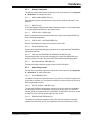
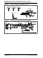
FIGURE A-1:
Figure A-4: Speech Processing Schematic
Figure A-5: Flash Memory Schematics
Figure A-6: Output Compare Module PWM Filters Schematic
Figure A-7: Audio Codec Schematic
Figure A-8: Audio Input Schematic
Figure A-9: Audio Output Schematic
Figure A-10: User LEDs, User Switches and Temp Sensor Schematics
DEBUG INPUT AND CONTROL SCHEMATIC – PART 1
PIC18F67J50
© 2008 Microchip Technology Inc.
DS51700A-page 31
MPLAB Starter Kit for dsPIC® DSCs User’s Guide
FIGURE A-2:
DEBUG INPUT AND CONTROL SCHEMATIC – PART 2
PIC18F67J50 Bypass/Decoupling Capacitors
Serial EEPROM
Status LED - Debug
FIGURE A-3:
USB Interface
(Bus Powered)
DS51700A-page 32
USB INTERFACE/TARGET POWER SWITCHING SCHEMATIC
3.3V LDO
Linear Regulator
Status LED System Power
Host MCU Switchable
3.3V Regulated Supply
© 2008 Microchip Technology Inc.
Schematics
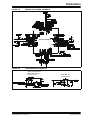
FIGURE A-4:
SPEECH PROCESSING SCHEMATIC
dsPIC33FJ256GP506
FIGURE A-5:
FLASH MEMORY SCHEMATICS
4 Mbit High Speed SPI
Serial Flash Memory
4 Mb (512k x 8)
© 2008 Microchip Technology Inc.
Flash Memory
3.3V Regulator
DS51700A-page 33
MPLAB Starter Kit for dsPIC® DSCs User’s Guide
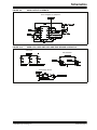
FIGURE A-6:
OUTPUT COMPARE MODULE PWM FILTERS SCHEMATIC
FIGURE A-7:
AUDIO CODEC SCHEMATIC
FIGURE A-8:
AUDIO INPUT SCHEMATIC
MIcrophone/Line Input Pre-Amplifier
Anti-Aliasing Filter
10
DS51700A-page 34
© 2008 Microchip Technology Inc.
Schematics
FIGURE A-9:
AUDIO OUTPUT SCHEMATIC
Power Amplifier for Headphone
FIGURE A-10:
USER LEDS, USER SWITCHES AND TEMP SENSOR SCHEMATICS
User LEDs
User Switches
Temperature Sensor
© 2008 Microchip Technology Inc.
DS51700A-page 35
MPLAB Starter Kit for dsPIC® DSCs User’s Guide
NOTES:
DS51700A-page 36
© 2008 Microchip Technology Inc.
MPLAB STARTER KIT FOR
dsPIC® DIGITAL SIGNAL CONTROLLERS
USER’S GUIDE
Index
A
O
Audio Codec Schematic........................................... 34
Audio I/O Schematics .........................................34, 35
OCPWM Filters Schematic ...................................... 34
B
Playback................................................................... 24
Programmer ............................................................. 20
PWM .......................................................................... 7
Bias Voltage............................................................. 23
Board Components .................................................. 26
Breakpoints .............................................................. 17
C
Codec....................................................................7, 24
Configuration Bits..................................................... 21
Customer Notification Service.................................... 4
Customer Support ...................................................... 5
D
Debug ...................................................................7, 25
Executive .......................................................... 16
Input and Control Schematic .......................31, 32
Reserved Resources ........................................ 20
Setup ................................................................ 16
Digital Volume Control ............................................. 24
Documentation
Conventions ........................................................ 2
Layout ................................................................. 1
F
Flash Memory .......................................................... 24
Flash Memory Schematic......................................... 33
Flow Chart................................................................ 11
G
G.711 μ-law algorithm .............................................. 10
H
Halt........................................................................... 17
Hardware Installation ............................................... 15
Headphone ................................................................ 7
Host Computer Requirements.................................... 8
P
R
Reading, Recommended ........................................... 3
Reserved Resources................................................ 20
Reset........................................................................ 17
Run........................................................................... 17
S
Schematic Diagrams ................................................ 31
Serial EEPROM ....................................................... 25
Software Installation................................................. 15
Speech Processing Schematic ................................ 33
Speech Sampling ..................................................... 23
Speech Sampling Interface Schematic .............. 31, 32
Step.......................................................................... 17
T
Target Power Switching Schematic ......................... 32
Temperature Sensor Schematic .............................. 33
Troubleshooting ....................................................... 21
U
Unable to Enter Debug Mode................................... 21
USB...................................................................... 7, 25
USB Interface Schematic ......................................... 32
W
Warranty Registration ................................................ 2
Watch Window ......................................................... 17
WWW Address........................................................... 4
I
Install........................................................................ 15
Internet Address......................................................... 4
L
Line Input ................................................................. 23
M
Manufacturers’ Data Sheets ...................................... 7
Microchip Internet Web Site ....................................... 4
Microphone ................................................................ 7
MPLAB IDE ...........................................................7, 15
© 2008 Microchip Technology Inc.
DS51700A-page 37
WORLDWIDE SALES AND SERVICE
AMERICAS
ASIA/PACIFIC
ASIA/PACIFIC
EUROPE
Corporate Office
2355 West Chandler Blvd.
Chandler, AZ 85224-6199
Tel: 480-792-7200
Fax: 480-792-7277
Technical Support:
http://support.microchip.com
Web Address:
www.microchip.com
Asia Pacific Office
Suites 3707-14, 37th Floor
Tower 6, The Gateway
Harbour City, Kowloon
Hong Kong
Tel: 852-2401-1200
Fax: 852-2401-3431
India - Bangalore
Tel: 91-80-4182-8400
Fax: 91-80-4182-8422
India - New Delhi
Tel: 91-11-4160-8631
Fax: 91-11-4160-8632
Austria - Wels
Tel: 43-7242-2244-39
Fax: 43-7242-2244-393
Denmark - Copenhagen
Tel: 45-4450-2828
Fax: 45-4485-2829
India - Pune
Tel: 91-20-2566-1512
Fax: 91-20-2566-1513
France - Paris
Tel: 33-1-69-53-63-20
Fax: 33-1-69-30-90-79
Japan - Yokohama
Tel: 81-45-471- 6166
Fax: 81-45-471-6122
Germany - Munich
Tel: 49-89-627-144-0
Fax: 49-89-627-144-44
Atlanta
Duluth, GA
Tel: 678-957-9614
Fax: 678-957-1455
Boston
Westborough, MA
Tel: 774-760-0087
Fax: 774-760-0088
Chicago
Itasca, IL
Tel: 630-285-0071
Fax: 630-285-0075
Dallas
Addison, TX
Tel: 972-818-7423
Fax: 972-818-2924
Detroit
Farmington Hills, MI
Tel: 248-538-2250
Fax: 248-538-2260
Kokomo
Kokomo, IN
Tel: 765-864-8360
Fax: 765-864-8387
Los Angeles
Mission Viejo, CA
Tel: 949-462-9523
Fax: 949-462-9608
Santa Clara
Santa Clara, CA
Tel: 408-961-6444
Fax: 408-961-6445
Toronto
Mississauga, Ontario,
Canada
Tel: 905-673-0699
Fax: 905-673-6509
Australia - Sydney
Tel: 61-2-9868-6733
Fax: 61-2-9868-6755
China - Beijing
Tel: 86-10-8528-2100
Fax: 86-10-8528-2104
China - Chengdu
Tel: 86-28-8665-5511
Fax: 86-28-8665-7889
Korea - Daegu
Tel: 82-53-744-4301
Fax: 82-53-744-4302
China - Hong Kong SAR
Tel: 852-2401-1200
Fax: 852-2401-3431
Korea - Seoul
Tel: 82-2-554-7200
Fax: 82-2-558-5932 or
82-2-558-5934
China - Nanjing
Tel: 86-25-8473-2460
Fax: 86-25-8473-2470
Malaysia - Kuala Lumpur
Tel: 60-3-6201-9857
Fax: 60-3-6201-9859
China - Qingdao
Tel: 86-532-8502-7355
Fax: 86-532-8502-7205
Malaysia - Penang
Tel: 60-4-227-8870
Fax: 60-4-227-4068
China - Shanghai
Tel: 86-21-5407-5533
Fax: 86-21-5407-5066
Philippines - Manila
Tel: 63-2-634-9065
Fax: 63-2-634-9069
China - Shenyang
Tel: 86-24-2334-2829
Fax: 86-24-2334-2393
Singapore
Tel: 65-6334-8870
Fax: 65-6334-8850
China - Shenzhen
Tel: 86-755-8203-2660
Fax: 86-755-8203-1760
Taiwan - Hsin Chu
Tel: 886-3-572-9526
Fax: 886-3-572-6459
China - Wuhan
Tel: 86-27-5980-5300
Fax: 86-27-5980-5118
Taiwan - Kaohsiung
Tel: 886-7-536-4818
Fax: 886-7-536-4803
China - Xiamen
Tel: 86-592-2388138
Fax: 86-592-2388130
Taiwan - Taipei
Tel: 886-2-2500-6610
Fax: 886-2-2508-0102
China - Xian
Tel: 86-29-8833-7252
Fax: 86-29-8833-7256
Thailand - Bangkok
Tel: 66-2-694-1351
Fax: 66-2-694-1350
Italy - Milan
Tel: 39-0331-742611
Fax: 39-0331-466781
Netherlands - Drunen
Tel: 31-416-690399
Fax: 31-416-690340
Spain - Madrid
Tel: 34-91-708-08-90
Fax: 34-91-708-08-91
UK - Wokingham
Tel: 44-118-921-5869
Fax: 44-118-921-5820
China - Zhuhai
Tel: 86-756-3210040
Fax: 86-756-3210049
01/02/08
DS51700A-page 38
© 2008 Microchip Technology Inc.
Mouser Electronics
Authorized Distributor
Click to View Pricing, Inventory, Delivery & Lifecycle Information:
Microchip:
DM330011