1
dsPICDEM.net™ 1
and dsPICDEM.net™ 2
Connectivity Development Board
User’s Guide
2004 Microchip Technology Inc.
DS51471A
Note the following details of the code protection feature on Microchip devices:
•
Microchip products meet the specification contained in their particular Microchip Data Sheet.
•
Microchip believes that its family of products is one of the most secure families of its kind on the market today, when used in the
intended manner and under normal conditions.
•
There are dishonest and possibly illegal methods used to breach the code protection feature. All of these methods, to our
knowledge, require using the Microchip products in a manner outside the operating specifications contained in Microchip’s Data
Sheets. Most likely, the person doing so is engaged in theft of intellectual property.
•
Microchip is willing to work with the customer who is concerned about the integrity of their code.
•
Neither Microchip nor any other semiconductor manufacturer can guarantee the security of their code. Code protection does not
mean that we are guaranteeing the product as “unbreakable.”
Code protection is constantly evolving. We at Microchip are committed to continuously improving the code protection features of our
products. Attempts to break Microchip’s code protection feature may be a violation of the Digital Millennium Copyright Act. If such acts
allow unauthorized access to your software or other copyrighted work, you may have a right to sue for relief under that Act.
Information contained in this publication regarding device
applications and the like is intended through suggestion only
and may be superseded by updates. It is your responsibility to
ensure that your application meets with your specifications.
No representation or warranty is given and no liability is
assumed by Microchip Technology Incorporated with respect
to the accuracy or use of such information, or infringement of
patents or other intellectual property rights arising from such
use or otherwise. Use of Microchip’s products as critical
components in life support systems is not authorized except
with express written approval by Microchip. No licenses are
conveyed, implicitly or otherwise, under any intellectual
property rights.
Trademarks
The Microchip name and logo, the Microchip logo, Accuron,
dsPIC, KEELOQ, microID, MPLAB, PIC, PICmicro, PICSTART,
PRO MATE, PowerSmart, rfPIC, and SmartShunt are
registered trademarks of Microchip Technology Incorporated
in the U.S.A. and other countries.
AmpLab, FilterLab, MXDEV, MXLAB, PICMASTER, SEEVAL,
SmartSensor and The Embedded Control Solutions Company
are registered trademarks of Microchip Technology
Incorporated in the U.S.A.
Analog-for-the-Digital Age, Application Maestro, dsPICDEM,
dsPICDEM.net, dsPICworks, ECAN, ECONOMONITOR,
FanSense, FlexROM, fuzzyLAB, In-Circuit Serial
Programming, ICSP, ICEPIC, Migratable Memory, MPASM,
MPLIB, MPLINK, MPSIM, PICkit, PICDEM, PICDEM.net,
PICLAB, PICtail, PowerCal, PowerInfo, PowerMate,
PowerTool, rfLAB, rfPICDEM, Select Mode, Smart Serial,
SmartTel and Total Endurance are trademarks of Microchip
Technology Incorporated in the U.S.A. and other countries.
SQTP is a service mark of Microchip Technology Incorporated
in the U.S.A.
All other trademarks mentioned herein are property of their
respective companies.
© 2004, Microchip Technology Incorporated, Printed in the
U.S.A., All Rights Reserved.
Printed on recycled paper.
Microchip received ISO/TS-16949:2002 quality system certification for
its worldwide headquarters, design and wafer fabrication facilities in
Chandler and Tempe, Arizona and Mountain View, California in
October 2003. The Company’s quality system processes and
procedures are for its PICmicro® 8-bit MCUs, KEELOQ® code hopping
devices, Serial EEPROMs, microperipherals, nonvolatile memory and
analog products. In addition, Microchip’s quality system for the design
and manufacture of development systems is ISO 9001:2000 certified.
DS51471A-page ii
2004 Microchip Technology Inc.
dsPICDEM.net™ 1 AND dsPICDEM.net 2
CONNECTIVITY DEVELOPMENT BOARD
USER’S GUIDE
Table of Contents
Preface ........................................................................................................................... 1
Chapter 1. Introduction
1.1 Introduction ..................................................................................................... 7
1.2 Highlights ........................................................................................................ 7
1.3 Overview ........................................................................................................ 7
1.4 dsPICDEM.net Package Contents ................................................................. 8
1.5 dsPICDEM.net Board Functionality ................................................................ 8
1.6 dsPICDEM.net Demonstration Programs ..................................................... 10
1.7 Reference Documents .................................................................................. 11
Chapter 2. Tutorial
2.1 Introduction ................................................................................................... 13
2.2 Highlights ...................................................................................................... 13
2.3 Tutorial Overview ......................................................................................... 13
2.4 Creating the Project ...................................................................................... 13
2.5 Building the Code ......................................................................................... 19
2.6 Device Configuration and Programming ...................................................... 22
2.7 Debugging the Code .................................................................................... 27
2.8 Summary ...................................................................................................... 30
Chapter 3. Quick Start Program
3.1 Introduction ................................................................................................... 31
3.2 Highlights ...................................................................................................... 31
3.3 Quick Start Program Overview ..................................................................... 31
3.4 Creating the Project ...................................................................................... 32
3.5 Building the Code ......................................................................................... 38
3.6 Device Configuration and Programming ...................................................... 40
3.7 Interacting with the Code .............................................................................. 45
3.8 Quick Start Demonstration Features and Peripherals .................................. 45
3.9 Data and Control Flow .................................................................................. 46
3.10 Summary .................................................................................................... 48
Chapter 4. HTTP Web Server Demonstration
4.1 Introduction ................................................................................................... 49
4.2 Highlights ...................................................................................................... 49
4.3 Demonstration Overview .............................................................................. 49
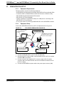
4.4 Demonstration Setup .................................................................................... 50
4.5 Configuring your Laptop or Desktop PC ....................................................... 51
4.6 HTTP Web Server Demonstration ............................................................... 52
2004 Microchip Technology Inc.
DS51471A-page iii
dsPICDEM.net 1 and dsPICDEM.net 2 Connectivity Dev Board User’s Guide
4.7 Debugging Tips ............................................................................................ 57
4.8 Troubleshooting ........................................................................................... 58
4.9 Using HTTP Web Server in Your Application ............................................... 59
Chapter 5. FTP Server
5.1 Introduction ................................................................................................... 61
5.1 Highlights ...................................................................................................... 61
5.2 Application Overview .................................................................................... 61
5.3 Demonstration Setup .................................................................................... 62
5.4 Configuring your Laptop or Desktop PC ....................................................... 63
5.5 FTP Server Demonstration ........................................................................... 64
5.6 Summary ...................................................................................................... 70
Chapter 6. V.22bis Soft Modem Demonstration
6.1 Introduction ................................................................................................... 71
6.1 Highlights ...................................................................................................... 71
6.2 Demonstration Overview .............................................................................. 71
6.3 Demonstration Configurations ...................................................................... 72
6.4 Demonstration Procedures ........................................................................... 74
6.5 Reprogramming the dsPIC30F6014 ............................................................. 76
6.6 Description of dsPIC30F Soft Modem .......................................................... 78
6.7 dsPIC30F Soft Modem AT Command Set ................................................... 79
6.8 Troubleshooting the Connection .................................................................. 81
6.9 Regulatory Compliance Reference Information ........................................... 84
6.10 ITU-T Specifications ................................................................................... 86
Chapter 7. dsPICDEM.net Development Hardware
7.1 dsPICDEM.net Hardware Components ........................................................ 87
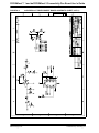
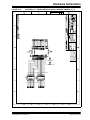
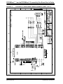
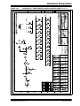
Appendix A. Hardware Schematics
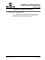
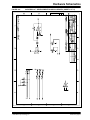
A.1 Board Layout and Schematics ..................................................................... 93
Index ...........................................................................................................................107
Worldwide Sales and Service ...................................................................................109
DS51471A-page iv
2004 Microchip Technology Inc.
dsPICDEM.net™ 1 AND dsPICDEM.net 2
CONNECTIVITY DEVELOPMENT BOARD
USER’S GUIDE
Preface
INTRODUCTION
This user’s guide supports the dsPICDEM.net 1 and dsPICDEM.net 2 connectivity
development boards. These boards provide basic platforms that enable the application
developer to create and evaluate both connectivity and non-connectivity based
solutions. This chapter previews the contents of the manual, tells you how to obtain
valuable customer support and recommends useful reference information.
HIGHLIGHTS
Items discussed in this chapter are:
•
•
•
•
•
•
About This Guide
Warranty Registration
Recommended Reading
The Microchip Web Site
Development Systems Customer Notification Service
Customer Support
ABOUT THIS GUIDE
This user’s guide describes how to use the dsPICDEM.net 1 and dsPICDEM.net 2
connectivity development boards. The document is organized as follows:
• Chapter 1: Introduction – This chapter introduces the dsPICDEM.net 1 and
dsPICDEM.net 2 connectivity development board and provides a brief description
of the hardware.
• Chapter 2: Tutorial – This chapter presents a step-by-step process for getting
your dsPICDEM.net 1 and dsPICDEM.net 2 connectivity development board up
and running with the MPLAB® In-Circuit Debugger 2 (MPLAB ICD 2).
• Chapter 3: Quick Start Program – This chapter describes the operational functionality of a demonstration program included on the dsPICDEM.net Development
Kit Software CD. The demonstration program exercises several capabilities of the
dsPIC30F by interacting with peripheral devices on the development board.
• Chapter 4: HTTP Web Server Demonstration – This chapter describes the
operational functionality of a sample HTTP Web Server based embedded
application that is included on the dsPICDEM.net Development Kit Software CD.
• Chapter 5: FTP Server Demonstration – This chapter describes the operational
functionality of a sample FTP Server based embedded application that is included
on the dsPICDEM.net Development Kit Software CD.
• Chapter 6: V.22bis Soft Modem Demonstration – This chapter describes the
operational functionality of a sample PSTN based application that is
preprogrammed into the dsPIC30F6014 device.
• Chapter 7: dsPICDEM.net™ Development Hardware – This chapter describes
the hardware included on the of the dsPICDEM.net 1 and dsPICDEM.net 2
boards.
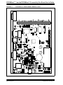
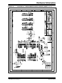
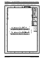
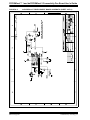
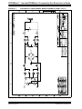
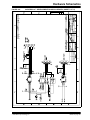
• Appendix A: Hardware Schematics – This Appendix contains hardware layout
and schematic diagrams of the dsPICDEM.net 1 and dsPICDEM.net 2.
2004 Microchip Technology Inc.
DS51471A-page 1
PICDEM.net™ 1 and dsPICDEM.net 2 Connectivity Dev Board User’s Guide
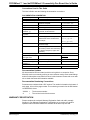
Conventions Used in This Guide
This User's Guide uses the following documentation conventions:
DOCUMENTATION CONVENTION
Description
Code (Courier font):
Plain characters
Angle brackets: < >
Square brackets [ ]
Curly brackets and pipe
character: { | }
Lower case characters
in quotes
Ellipses...
0xnnn
Represents
Examples
Sample code
Filenames and paths
Variables
Optional arguments
Choice of mutually exclusive
arguments; an OR selection
Type of data
#define START
c:\autoexec.bat
<label>, <exp>
pic30-as [main.s]
errorlevel {0|1}
Used to imply (but not show)
additional text that is not relevant to
the example
list
["list_option...,
"filename"
"list_option"]
A hexadecimal number where n is a
0xFFFF, 0x007A
hexadecimal digit
A variable argument; it can be either a char isascii (char,
type of data (in lower case characters) ch);
or a specific example (in upper case
characters)
Italic characters
Interface (Arial font):
Underlined, italic text
with right arrow
Bold characters
Characters in angle
brackets < >
Documents (Arial font):
Italic characters
A menu selection from the menu bar
File > Save
A window or dialog button to click
A key on the keyboard
OK, Cancel
<Tab>, <Ctrl-C>
Referenced books
MPLAB IDE User’s Guide
Documentation Updates
All documentation becomes dated, and this user’s guide is no exception. Since
Microchip tools are constantly evolving to meet customer needs, some actual dialogs
and/or tool descriptions may differ from those in this document. Please refer to our web
site to obtain the latest documentation available.
Documentation Numbering Conventions
Documents are numbered with a “DS” number. The number is located on the bottom of
each page, in front of the page number. The numbering convention for the DS Number
is DSXXXXXA, where:
XXXXX
=
The document number.
A
=
The revision level of the document.
WARRANTY REGISTRATION
Please complete the enclosed Warranty Registration Card and mail it promptly.
Sending in your Warranty Registration Card entitles you to receive new product
updates. Interim software releases are available at the Microchip web site.
DS51471A-page 2
2004 Microchip Technology Inc.
Preface
RECOMMENDED READING
This user’s guide describes how to use the dsPICDEM.net 1 and dsPICDEM.net 2
Connectivity Development Board. Other useful documents include:
dsPIC30F Family Reference Manual (DS70046)
Consult this document for detailed information on dsPIC30F device operation. This
reference manual explains the operation of the dsPIC30F MCU family architecture and
peripheral modules but does not cover the specifics of each device. Refer to the
appropriate device data sheet for device-specific information.
dsPIC30F Data Sheet, Motor Control and Power Conversion Family (DS70082)
Consult this document for detailed information on the dsPIC30F Motor Control and
Power Conversion devices. Reference information found in this data sheet includes:
•
•
•
•
Device memory map
Device pinout and packaging details
Device electrical specifications
List of peripherals included on the device
dsPIC30F Data Sheet, General Purpose and Sensor Families (DS70083)
Consult this document for detailed information on the dsPIC30F Sensor and General
Purpose devices. Reference information found in this data sheet includes:
•
•
•
•
Device memory map
Device pinout and packaging details
Device electrical specifications
List of peripherals included on the device
dsPIC30F5011, dsPIC30F5013 Data Sheet, High Performance Digital Signal
Controllers (DS70116)
This data sheet contains specific information for the dsPIC30F5011/5013 Digital Signal
Controller (DSC) devices.
dsPIC30F6011, dsPIC30F6012, dsPIC30F6013, dsPIC30F6014 Data Sheet, High
Performance Digital Signal Controllers (DS70117)
This data sheet contains specific information for the dsPIC30F6011/6012/6013/6014
Digital Signal Controller (DSC) devices.
dsPIC30F Programmer’s Reference Manual (DS70030)
This manual is a software developer’s reference for the dsPIC30F 16-bit MCU family
of devices. This manual describes the instruction set in detail and also provides general
information to assist you in developing software for the dsPIC30F MCU family.
dsPIC30F Family Overview (DS70043)
This document provides an overview of the functionality of the dsPIC® product family.
It helps determine how the dsPIC30F 16-bit Digital Signal Controller Family fits a
specific product application. This document is a supplement to the dsPIC30F Family
Reference Manual.
MPLAB® ASM30, MPLAB® LINK30 and Utilities User's Guide (DS51317)
This document helps you use Microchip Technology’s language tools for dsPIC devices
based on GNU technology. The language tools discussed are:
•
•
•
•
MPLAB ASM30 Assembler
MPLAB LINK30 Linker
MPLAB LIB30 Archiver/Librarian
Other Utilities
2004 Microchip Technology Inc.
DS51471A-page 3
PICDEM.net™ 1 and dsPICDEM.net 2 Connectivity Dev Board User’s Guide
MPLAB C30 C Compiler User’s Guide (DS51284)
This document details the use of Microchip’s MPLAB C30 C Compiler for dsPIC
devices to develop an application. MPLAB C30 is a GNU-based language tool, based
on source code from the Free Software Foundation (FSF). For more information about
the FSF, see www.fsf.org.
Other GNU language tools available from Microchip are:
• MPLAB ASM30 Assembler
• MPLAB LINK30 Linker
• MPLAB LIB30 Librarian/Archiver
dsPIC™ Language Tools Libraries (DS51456)
DSP, dsPIC peripheral and standard (including math) libraries for use with dsPIC
language tools.
GNU HTML Documentation
This documentation is provided on the language tool CD-ROM. It describes the
standard GNU development tools, upon which these tools are based.
MPLAB® IDE Simulator, Editor User’s Guide (DS51025)
Consult this document for more information pertaining to the installation and
implementation of the MPLAB Integrated Development Environment (IDE) Software.
To obtain any of these documents, visit the Microchip web site at www.microchip.com.
THE MICROCHIP WEB SITE
Microchip provides online support on the Microchip World Wide Web (WWW) site. The
web site is used by Microchip as a means to make files and information easily available
to customers. To view the site, you must have access to the Internet and a web
browser, such as, Netscape® Navigator or Microsoft® Internet Explorer. The Microchip
web site is available at:www.microchip.com.
The web site provides a variety of services. Users may download files for the latest
development tools, data sheets, application notes, user's guides, articles and sample
programs. A variety of information specific to the business of Microchip is also
available, including listings of Microchip sales offices, distributors and factory
representatives.
Technical Support
• Frequently Asked Questions (FAQ)
• Online Discussion Groups – conferences for products, development systems,
technical information and more
• Microchip Consultant Program Member Listing
• Links to other useful web sites related to Microchip products
Engineer’s Toolbox
• Design Tips
• Device Errata
Other Available Information
• Latest Microchip Press Releases
• Listing of Seminars and Events
• Job Postings
DS51471A-page 4
2004 Microchip Technology Inc.
Preface
DEVELOPMENT SYSTEMS CUSTOMER NOTIFICATION SERVICE
Microchip started the customer notification service to help our customers stay current
on Microchip products with the least amount of effort. Once you subscribe, you will
receive E-mail notification whenever we change, update, revise or have errata related
to your specified product family or development tool of interest.
Go to the Microchip web site at (www.microchip.com) and click on Customer Change
Notification. Follow the instructions to register.
The Development Systems product group categories are:
•
•
•
•
•
Compilers
Emulators
In-Circuit Debuggers
MPLAB
Programmers
Here is a description of these categories:
Compilers – The latest information on Microchip C compilers and other language
tools. These include the MPLAB C17, MPLAB C18 and MPLAB C30 C compilers;
MPASM™ and MPLAB ASM30 assemblers; MPLINK™ and MPLAB LINK30 object
linkers; MPLIB™ and MPLAB LIB30 object librarians.
Emulators – The latest information on Microchip in-circuit emulators. This includes the
MPLAB ICE 2000 and MPLAB ICE 4000.
In-Circuit Debuggers – The latest information on Microchip in-circuit debuggers.
These include the MPLAB ICD and MPLAB ICD 2.
MPLAB – The latest information on Microchip MPLAB IDE, the Windows Integrated
Development Environment for development systems tools. This list is focused on the
MPLAB IDE, MPLAB SIM and MPLAB SIM30 simulators, MPLAB IDE Project Manager
and general editing and debugging features.
Programmers – The latest information on Microchip device programmers. These
include the PRO MATE® II device programmer and PICSTART® Plus development
programmer.
2004 Microchip Technology Inc.
DS51471A-page 5
PICDEM.net™ 1 and dsPICDEM.net 2 Connectivity Dev Board User’s Guide
CUSTOMER SUPPORT
Users of Microchip products can receive assistance through several channels:
•
•
•
•
•
Distributor or Representative
Local Sales Office
Field Application Engineer (FAE)
Corporate Applications Engineer (CAE)
Hotline
Customers should call their distributor, representative or field application engineer
(FAE) for support. Local sales offices are also available to help customers. See the
sales offices and locations listed on the back of this publication.
Corporate Applications Engineers (CAEs) may be contacted at (480) 792-7627.
In addition, there is a Systems Information and Upgrade Line. This line provides system
users a listing of the latest versions of all of Microchip's development systems software
products. Plus, this line provides information on how customers can receive any
currently available upgrade kits.
The Hotline Numbers are:
1-800-755-2345 for U.S. and most of Canada.
1-480-792-7302 for the rest of the world.
DS51471A-page 6
2004 Microchip Technology Inc.
dsPICDEM.net™ 1 AND dsPICDEM.net 2
CONNECTIVITY DEVELOPMENT BOARD
USER’S GUIDE
Chapter 1. Introduction
1.1
INTRODUCTION
This chapter introduces several connectivity capabilities that can easily be
implemented with the use of the dsPICDEM.net Connectivity Development Board.
1.2
HIGHLIGHTS
This chapter discusses:
•
•
•
•
•
1.3
Overview
dsPICDEM.net Package Contents
dsPICDEM.net Board Functionality
dsPICDEM.net Demonstration Programs
Reference Documents
OVERVIEW
The dsPICDEM.net 1 and dsPICDEM.net 2 connectivity development boards are tools
designed to help the application developer create and evaluate both connectivity and
non-connectivity based solutions using dsPIC30F High Performance Digital Signal
Controllers. The dsPICDEM.net 1 board supports the Federal Communications
Commission (FCC) and Japan Approval Institute for Telecommunications Equipment
(JATE) country specific Public Switched Telephone Network (PSTN). The
dsPICDEM.net 2 board supports the Common Technical Regulation 21 (CTR-21)
PSTN. Both boards support the Realtek 10-base T Ethernet Network Interface
Controller (NIC).
Every country has telecommunication laws that prohibit the connection of unapproved
telecommunication devices, including modems, to the phone line. Approval by a
country's telecommunications regulatory agency may entail hardware/firmware
modifications to your end-system modem in order to comply with their
telecommunication laws relative to radio-frequency interference, pulse dial make/break
ratios, redial capabilities, etc.
The words “approved or compliant for use in country XYZ” mean that the modem has
been modified to comply with the telecommunication laws of that country. Thus, a
modem approved by the FCC to work in the USA, for example, is not automatically
approved by the BZT to work in Germany.
Note:
2004 Microchip Technology Inc.
For the sample applications described in this manual, connect to an analog
line only. You could damage the modem if you use a non-analog line
(e.g., digital or PBX multiline).
DS51471A-page 7
PICDEM.net™ 1 and dsPICDEM.net 2 Connectivity Dev Board User’s Guide
The boards come with an ITU-T compliant V.22bis/V.22 modem module and
demonstration code pre-programmed on the installed dsPIC30F6014 device. This
sample application lets you to connect and transfer data between the dsPIC30F Soft
Modem and an ITU-T compliant reference modem. Application source code is included
on the supplied development kit software CD.
The Development Kit Software CD also includes additional sample applications, a
tutorial module and complete product documentation. The additional sample
applications will familiarize you with the CMX-MicroNet HTTP Web and FTP Servers,
which demonstrate two TCP/IP protocol based applications over the 10-Base T
Ethernet Datalink layer. Product tutorials provide hands-on experience in debugging
with the MPLAB ICD 2.
1.4
dsPICDEM.net PACKAGE CONTENTS
The following items comprise the dsPICDEM.net Connectivity Development Board
package:
• The dsPICDEM.net 1 or dsPICDEM.net 2 Printed Circuit Board (supports both
embedded internet and ethernet connections).
• A pre-programmed dsPIC30F6014 device on an adapter board that plugs into the
main development board
• A CAT5 “crossover” network cable (RJ45 connectors) for networking the board.
• 9 VDC Power Supply
• RS-232 Interface Cable
• dsPICDEM.net Development Kit Software CD containing demonstration
connectivity solutions from Microchip and it’s partners along with a product tutorial
and complete documentation.
1.5
dsPICDEM.net BOARD FUNCTIONALITY
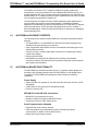
The dsPICDEM.net Development Board (Figure 1-1) provides a basic platform for
developing and evaluating solutions that use dsPIC30F6014 16-bit Digital Signal
Controllers. The dsPICDEM.net Development Board includes the following
capabilities:
Power Supply
• Single on-board +5V regulator for VDD and AVDD with direct input from 9V, AC/DC
wall adapter
• 9 VDC power source input jack for development board
• Power-on indicator LED
MPLAB ICD 2 and ICE 4000 Connections
• MPLAB ICD 2 programming connector
• Emulation header connection to MPLAB ICE 4000
• Pad location for 80-pin TQFP dsPIC device
Serial Communication Channels
• Single RS-232 communication channel
• 6-pin terminal block and configuration jumper for RS-485 and RS-422
communication on UART1 from the dsPIC device
• Single CAN communication channel
DS51471A-page 8
2004 Microchip Technology Inc.
Introduction
Public-Switched Telephone Network (PSTN)
•
•
•
•
Silicon Laboratories Si3035 DAA/AFE chipset (dsPICDEM.net 1 board)
Silicon Laboratories Si3034 DAA/AFE chipset (dsPICDEM.net 2 board)
Speaker for monitoring call progress
Si3021 reset push button switch
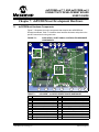
FIGURE 1-1:
dsPICDEM.net DEVELOPMENT BOARD
10-BaseT Ethernet
• Realtek RTL8019AS 10-Base T single-chip Network Interface Controller and
transceiver
• Four link status LEDs
• RJ-45 (10-Base T) modular connector
Analog
•
•
•
•
Two 5 kΩ Potentiometers (RP1 and RP2)
Microchip MCP42050 Digital Potentiometer (dual-channel output)
Microchip TC1047A Thermal Sensor (U2)
Microchip MCP602 op amp configured as low-pass filter for thermal sensor (U12)
Device Clocking
• 7.3728 MHz crystal, X3, for dsPIC device
• Socket U16, clock oscillator for dsPIC device (alternate clock source, X3
removed)
• Pad for 32.768 kHz crystal (XTAL2) and load caps
2004 Microchip Technology Inc.
DS51471A-page 9
PICDEM.net™ 1 and dsPICDEM.net 2 Connectivity Dev Board User’s Guide
Miscellaneous
•
•
•
•
•
•
•
•
1.6
Reset push button switch
Three red LEDs (LED1-LED3)
Three push button switches (S1-S3) for external input stimulus
64k x 16 External SRAM
Microchip 24LC515 Serial EE memory device
2 x 16 character LCD
2 x 50 prototyping header for user hardware expansion (header not installed)
Prototype area for user hardware
dsPICDEM.net DEMONSTRATION PROGRAMS
The dsPICDEM.net Development Board is supplied with several sample application
programs for the dsPIC30F6014 to help you jump-start your own solutions. You will
need the MPLAB C30 Compiler to program these applications into the dsPIC30F
device. You can download a full-featured 60-day trial version of MPLAB C30 from the
Microchip web site (www.microchip.com). Follow the download links under
Products/Development Tools/Software.
Source code is provided on the Development Kit Software CD for all these
demonstration programs:
• Tutorial – The tutorial introduces the new user to the basic skills needed to work
with the dsPIC30F. It provides step-by-step instructions for programming the
dsPIC30F chip with the MPLAB IDE and MPLAB C30 and debugging the program
with the MPLAB ICD 2. See Chapter 2. “Tutorial”.
• dsPIC30F Quick Start – Building on the tutorial, the dcPIC30F demonstration
uses a sample application to illustrate functionality of the dsPIC30F and its
peripherals interacting with components on the dsPICDEM.net board. This
application is described fully in Chapter 3. “Quick Start Program”.
• HTTP Web Server Demonstration – This sample application illustrates an
embedded web server that supports remote monitoring and control over a
10-Base T Ethernet connection. This demonstration program uses the
CMX-MicroNet TCP/IP Stack configured for HTTP Web Server protocol. This
sample application is described fully in Chapter 4. “HTTP Web Server
Demonstration”.
• FTP Server Demonstration – This demonstration illustrates an embedded FTP
server application that provides remote monitoring and control over a 10-Base T
Ethernet connection. This sample application uses the CMX-MicroNet TCP/IP
Stack configured for FTP Server protocol. This demonstration is described fully in
Chapter 5. “FTP Server Demonstration”.
• V.22bis Soft Modem Demonstration – The dsPIC30F6014 plug-in device is
pre-programmed with an ITU-T compliant V.22bis/V.22 modem demonstration that
lets you to connect and transfer data between the dsPIC30F Soft Modem and an
ITU-T compliant reference modem. This demonstration is described fully in
Chapter 6. “V.22bis Soft Modem Demonstration”.
DS51471A-page 10
2004 Microchip Technology Inc.
Introduction
1.7
REFERENCE DOCUMENTS
The following documentation is available to support your use of the dsPICDEM.net
Development Board:
•
•
•
•
•
•
•
•
•
•
•
dsPIC30F Family Reference Manual (DS70046)
dsPIC30F Data Sheet, Motor Control and Power Conversion Family (DS70082)
dsPIC30F Data Sheet, General Purpose and Sensor Families (DS70083)
dsPIC30F5011, dsPIC30F5013 Data Sheet, High Performance Digital Signal
Controllers (DS70116)
dsPIC30F6011, dsPIC30F6012, dsPIC30F6013, dsPIC30F6014 Data Sheet, High
Performance Digital Signal Controllers (DS70117)
dsPIC30F Programmer’s Reference Manual (DS70030)
dsPIC High Performance 16-bit Digital Signal Controller Family Overview
(DS70043)
MPLAB C30 C Compiler User’s Guide (DS51284)
MPLAB ASM30, MPLAB LINK30 and Utilities User’s Guide (DS51317)
MPLAB ICD 2 In-Circuit Debugger Quick Start Guide (DS51268)
MPLAB ICE Emulator User’s Guide (DS51159)
You can obtain these reference documents from your nearest Microchip sales office
(listed in the back of this document) or by downloading them from the Microchip web
site (www.microchip.com).
2004 Microchip Technology Inc.
DS51471A-page 11
PICDEM.net™ 1 and dsPICDEM.net 2 Connectivity Dev Board User’s Guide
NOTES:
DS51471A-page 12
2004 Microchip Technology Inc.
dsPICDEM.net™ 1 AND dsPICDEM.net 2
CONNECTIVITY DEVELOPMENT BOARD
USER’S GUIDE
Chapter 2. Tutorial
2.1
INTRODUCTION
This chapter is a self-paced tutorial intended to get you started using the
dsPICDEM.net Development Board. The tutorial demonstrates basic techniques for
using the dsPIC30F development tools with the connectivity board.
2.2
HIGHLIGHTS
This chapter discusses:
•
•
•
•
•
•
2.3
Tutorial Overview
Creating the Project
Building the Code
Programming the Chip
Debugging the Code
Summary
TUTORIAL OVERVIEW
This tutorial combines step-by-step instructions for using the dsPIC development tools
with files provided on the Development Kit Software CD to exercise key features of the
MPLAB IDE, MPLAB ICD 2 and MPLAB C30 for programming and debugging the
dsPIC30F chip.
There are three or four steps to this tutorial, depending on the debug tool being used.
1.
2.
3.
4.
Create a project in MPLAB
Assemble and link the code
Program the chip if the MPLAB ICD 2 is being used
Debug the code with the MPLAB ICD 2
The MPLAB ICD 2 is used in the tutorial to illustrate debugging.
2.4
CREATING THE PROJECT
The first step is to create a project and a workspace in MPLAB. Usually, you will have
one project in one workspace. A project contains the files needed to build an application
(source code, linker script files, etc.) along with their associations to various build tools
and build options. A workspace contains one or more projects and information on the
selected device, debug tool and/or programmer, open windows and their location, and
other IDE configuration settings. MPLAB IDE contains a Project Wizard to help create
new projects.
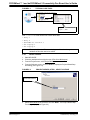
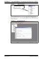
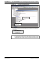
Before starting, copy the Tutorial files from the dsPICDEM.net Sample Applications
folder on the dsPICDEM.net Development Kit Software CD to your c:\ drive (see
Figure 2-1).
2004 Microchip Technology Inc.
DS51471A-page 13
PICDEM.net™ 1 and dsPICDEM.net 2 Connectivity Dev Board User’s Guide
FIGURE 2-1:
TUTORIAL CODE FILES
Copy Tutorial folder from CD
to your C:\ drive
Your c:\Tutorial folder should now contain these files:
•
•
•
•
•
delay.c
delay.h
dsPICDEM net Tutorial.c
LCD Display.c
LCD Display.h
Note:
2.4.1
1.
2.
3.
4.
Files copied from the CD are read only; you will need to change the
attributes of files that need to be edited.
Select a Device
Start MPLAB IDE
Close any workspace that might be open (File>Close Workspace).
From the Project menu, select Project Wizard.
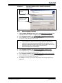
From the Welcome screen, click the Next> to display the Project Wizard Step
One dialog (see Figure 2-2).
FIGURE 2-2:
PROJECT WIZARD, STEP 1, SELECT A DEVICE
Select dsPIC30F6014
5. Select dsPIC30F6014 as the device and click Next>. The Project Wizard Step
Two dialog displays (see Figure 2-3).
DS51471A-page 14
2004 Microchip Technology Inc.
Tutorial
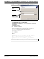
FIGURE 2-3:
PROJECT WIZARD, STEP 2, SELECT LANGUAGE
TOOLSUITE
Select Microchip C30
Toolsuite
Specify file locations for
Assembler, Compiler
and Object Linker
2.4.2
Select Language Toolsuite
1. From the Active Toolsuite pull-down menu, select Microchip C30 Toolsuite. This
toolsuite includes the compiler, assembler and linker that will be used.
2. From Toolsuite Contents, select MPLAB ASM 30 Assembler (pic30-as.exe).
3. In the Location group, click Browse... and navigate to:
C:\pic30_tools\Bin\pic30-as.exe
Note:
C:\ is the drive implemented for this tutorial example. The specific location
on your system will depend on where you installed the MPLAB C30
compiler. If you haven’t purchased the MPLAB C30 compiler, you can
download a full-featured 60-day trial version from the Microchip web site
(www.microchip.com). Follow the download links under
Products/Development Tools/Software.
4. From Toolsuite Contents, select MPLAB C30 Compiler (pic30-gcc.exe).
5. In the Location block, click Browse... and navigate to:
C:\pic30_tools\Bin\pic30-gcc.exe
6. From Toolsuite Contents, select MPLAB LINK30 Object Linker (pic30-Id.exe).
7. In the Location block, click Browse... and navigate to:
C:\pic30_tools\Bin\pic30-ld.exe.
8. Click Next> to continue. The Project Wizard Step Three dialog displays (see
Figure 2-4).
2004 Microchip Technology Inc.
DS51471A-page 15
PICDEM.net™ 1 and dsPICDEM.net 2 Connectivity Dev Board User’s Guide
FIGURE 2-4:
PROJECT WIZARD, STEP 3, NAME YOUR PROJECT
Type a name for your
project...
...and save it in the Project
Directory (C:\Tutorial)
2.4.3
Name Your Project
1. In the Project Name text box, type MyTutorial.
2. Click Browse... and navigate to C:\Tutorial to place your project in the
Tutorial folder.
3. Click Next> to continue.
2.4.4
Add Files to Project
1. On the Project Wizard Step Four dialog (see Figure 2-5), locate the
C:\Tutorial folder and add these files to the right side.
dsPICDEMnet Tutorial.c
LCD Display.c
LCD Display.h
delay.c
delay.h
2. Navigate to the C:\pic30_tools\support\gld folder and add file
p30f6014.gld to include the linker script file in the project.
3. Navigate to the C:\pic30_tools\support\h folder and add file
p30f6014.h to include the header file in the project.
Note:
DS51471A-page 16
The linker script file and header file locations for your environment may be
different. The location will depend on where you installed the C30 compiler.
2004 Microchip Technology Inc.
Tutorial
FIGURE 2-5:
PROJECT WIZARD, STEP 4, ADD FILES TO PROJECT
Add the Tutorial files and
dsPIC30F6014 support
files for the to your newly
created project
4. There should now be seven files in the project. Click Next> to continue. The
Project Wizard Summary screen (Figure 2-6) displays the parameters of your
project.
FIGURE 2-6:
PROJECT WIZARD SUMMARY SCREEN
Project named “MyTutorial”
for dsPIC30F6014 device
will be saved to C:\Tutorial
5.
Click Finish.
After the project wizard completes, the MPLAB project window shows the project and
all the added files (see Figure 2-7).
2004 Microchip Technology Inc.
DS51471A-page 17
PICDEM.net™ 1 and dsPICDEM.net 2 Connectivity Dev Board User’s Guide
FIGURE 2-7:
PROJECT WINDOW
Project window displays the source
files, header files and linker script file
you added to your project
At this point a project and workspace have been created in MPLAB. MyTutorial.mcw
is the workspace file and MyTutorial.mcp is the project file. Double-click the
dsPICDEMnet Tutorial.c file in the project window to open it. MPLAB should look
similar to Figure 2-8.
FIGURE 2-8:
DS51471A-page 18
MPLAB WORKSPACE
2004 Microchip Technology Inc.
Tutorial
2.5
BUILDING THE CODE
In this project, the code is built in two stages, as shown in Figure 2-9. First the source
files are compiled into object files, then the object files are linked.
FIGURE 2-9:
CODE BUILDING PROCESS
dsPICDEM.net Tutorial.c
Compile
STAGE ONE
COMPILE
dsPICDEM.net Tutorial.o
delay.c
LCD display.c
Compile
LCD display.o
STAGE TWO
LINK
STAGE ONE
COMPILE
Compile
delay.o
Link
MyTutorial.cof
MyTutorial.hex
The MyTutorial.hex output file contains the data necessary to program the device.
The MyTutorial.cof output file contains additional information that lets you debug
the code at the source code level.
Before building, there are compiler and linker settings that must be specified. These
settings indicate where to find the C library files and where to reserve space for the
extra debug code when the MPLAB ICD 2 (In-Circuit Debugger) is used.
2.5.1
Set Project Build Options
The tutorial project does not explicitly use any libraries, but the C compiler startup
library code is always automatically linked into the project. Use the Project>Build
Options>Project menu to specify the location of the library files as shown in
Figure 2-10.
2004 Microchip Technology Inc.
DS51471A-page 19
PICDEM.net™ 1 and dsPICDEM.net 2 Connectivity Dev Board User’s Guide
FIGURE 2-10:
BUILD OPTIONS
Let the project know where the
library files are located
1. Select the Build Options General tab.
2. Add a Library Path by browsing to:
C:\pic30_tools\lib
Note:
The library path for your environment may be different. The location will
depend on where you installed the C30 compiler.
3. Select the MPLAB LINK30 tab to display the linker settings (see Figure 2-11).
DS51471A-page 20
2004 Microchip Technology Inc.
Tutorial
FIGURE 2-11:
MPLAB LINK30 BUILD OPTIONS
Check Link for ICD2
4. Check Link for ICD2 to tell the linker to reserve space for the debug code used
by the MPLAB ICD 2 In-Circuit Debugger.
5. Click OK.
2.5.2
Build the Project
At this point the project is ready to build.
1. From the Project menu select Make. The Build Output window displays (see
Figure 2-12).
2. Observe the progress of the build.
3. When the BUILD SUCCEEDED message displays you are ready to program the
device.
2004 Microchip Technology Inc.
DS51471A-page 21
PICDEM.net™ 1 and dsPICDEM.net 2 Connectivity Dev Board User’s Guide
FIGURE 2-12:
BUILD OUTPUT
If you experience problems with the build, double check all the steps in this tutorial and
ensure that you are using the latest versions of the development tools. The latest
upgrades are available on the Microchip web site (www.microchip.com).
If there are errors in the source code, you can double-click the error messages in the
Output window and MPLAB will point to the offending line in the source code. This
should not happen if the files were copied from the dsPICDEM.net Development Kit
CD.
2.6
DEVICE CONFIGURATION AND PROGRAMMING
After you have built the code you must set up the configuration bits and then connect
the tool you plan to use for programming, running and debugging the code.
Note:
2.6.1
Before proceeding, make sure that the USB driver for the MPLAB ICD 2 has
been installed on your PC (see the MPLAB ICD 2 User’s Guide (DS51331)
for more details regarding the installation of the USB driver).
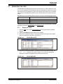
Set Up Device Configuration
From the Configure menu select Configuration Bits to view the configuration bits (see
Figure 2-13). Accept the settings resulting from your build. However, make sure these
device categories are set up as shown here:
DS51471A-page 22
Category
Setting
Oscillator Source
Primary Oscillator
Primary Oscillator Mode
XT w/PLL 4x
Watchdog Timer
Disabled
Comm Channel Select
Use PGC/EMUC and PGD/EMUD
2004 Microchip Technology Inc.
Tutorial
FIGURE 2-13:
CONFIGURATION SETTINGS
After building the code and setting the configuration bits, use the MPLAB ICD 2
debugger to program the device and run and debug the code on the dsPICDEM.net
Demonstration Board.
2.6.2
Enabling the MPLAB ICD 2 Connection
The MPLAB ICD 2 can be used to program and debug the dsPIC30F6014 device
in-circuit on the dsPICDEM.net board.
Note:
Before proceeding, make sure that the USB driver for the MPLAB ICD 2 has
been installed on your PC (see the MPLAB ICD 2 User’s Guide (DS51331)
for details regarding the installation of the USB driver).
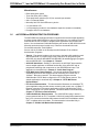
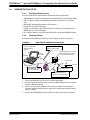
1. Connect the MPLAB ICD 2 to the PC with the USB cable (see Figure 2-14).
2. Connect the MPLAB ICD 2 to modular connector labeled ICD on the
dsPICDEM.net board with the provided short RJ-11cable.
3. Apply power to the board.
FIGURE 2-14:
TUTORIAL DEMONSTRATION SETUP
PC running MPLAB® IDE
Connect MPLAB® ICD 2 to
PC with USB cable
dsPICDEM.net™ Connectivity
Development Board
running Tutorial program
USB Port
J14
ICD
Power Cable
9 VDC
115 VAC
MPLAB ICD 2
Connect MPLAB® ICD 2 to board
with provided RJ-11 cable
2004 Microchip Technology Inc.
Apply power to the board
DS51471A-page 23
PICDEM.net™ 1 and dsPICDEM.net 2 Connectivity Dev Board User’s Guide
4. From the Debugger>Select Tool menu, select MPLAB ICD 2 as the debug tool.
5. From the Debugger menu, select Connect. MPLAB should report that it found the
dsPIC30F6014 as shown in Figure 2-15.
Note:
MPLAB may need to download new firmware if this is the first time the
MPLAB ICD 2 is being used with a dsPIC30F device. Allow it to do so. If
any errors are shown, double-click the error message to get more
information.
FIGURE 2-15:
ENABLING MPLAB ICD 2
6. From the Debugger menu, select Settings to display the ICD Debugger settings
(see Figure 2-16).
FIGURE 2-16:
MPLAB ICD 2 DEBUGGER SETTINGS
Make sure this option is selected:
Allow MPLAB ICD 2 to select
memories and ranges
DS51471A-page 24
2004 Microchip Technology Inc.
Tutorial
7. On the Program tab, ensure that Allow ICD 2 to select memories and ranges
is selected. This setting will speed up programming by addressing only a small
part of the total program memory.
8. Program the part (Debugger>Program). The Output window shows the results of
the programming cycle as shown in Figure 2-17. The part is now programmed
and is ready to run.
FIGURE 2-17:
MPLAB ICD 2 PROGRAM READY
9. Run the code (Debugger>Run). The MPLAB Output window should indicate that
the target is running (see Figure 2-18).
2004 Microchip Technology Inc.
DS51471A-page 25
PICDEM.net™ 1 and dsPICDEM.net 2 Connectivity Dev Board User’s Guide
FIGURE 2-18:
TUTORIAL PROGRAM RUNNING
Project status bar
shows program running
Output window shows
program running
On the board, LED2 should start blinking and the LCD display should display the
following text:
dsPICDEM.net
Tutorial
Note:
DS51471A-page 26
When debugging with MPLAB ICD 2, it is always necessary to reprogram
the part with the new code after each build. MPLAB will remind you with a
message that states “Program memory has changed since last operation.”
2004 Microchip Technology Inc.
Tutorial
2.7
DEBUGGING THE CODE
The MPLAB ICD 2 debugger/programmer can be used to run, halt, and step the code.
You can set a breakpoint so that program execution halts after the code has executed
the instruction at the breakpoint. A green arrow points to the next line to be executed.
The contents of the RAM and registers can be viewed when the processor has been
halted.
MPLAB ICD 2 uses the following function keys to access the main debugging functions:
<F5>
Halt
<F6>
Reset
<F7>
Single Step
<F9>
Run
There are more functions available by right clicking on a line of source code. The most
important of these are Set Breakpoint and Run to Cursor.
2.7.1
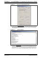
Display the Code
1. From the View menu, select Program Memory. The Program Memory window
displays.
2. Select the Symbolic tab at the bottom of the window.
3. Press <F5> to halt the processor. The program stops and the green arrow points
to the next instruction, as shown in Figure 2-19.
FIGURE 2-19:
PROGRAM HALTED
4. Press <F6> to reset the program. The green arrow moves to address 00000, the
goto _reset instruction, as shown in Figure 2-20. The linker inserted this
instruction to make the program branch to the start of the code.
FIGURE 2-20:
2004 Microchip Technology Inc.
PROGRAM RESET
DS51471A-page 27
PICDEM.net™ 1 and dsPICDEM.net 2 Connectivity Dev Board User’s Guide
2.7.2
Step the Program
1. Press <F7> to single step the code. The green arrow moves to line 129, _reset
mov.w #0x850,w15, as shown in Figure 2-21.
This code comes from a library (archive) file, libpic30.a, which is
automatically linked into C30 compiler projects. This code line initializes the stack
pointer and is part of the initialization code that the C30 compiler uses to set up
the stack and initialize data. Notice line 135, call main. This instruction calls
the main() routine from the dsPICDEMnet Tutorial.c source file.
FIGURE 2-21:
PROGRAM SINGLE STEPPED
2. Open the dsPICDEMnet Tutorial.c source file. Double click on the file name
in the Project Window if the file is not already open.
3. Select and right click line TMR1 = 0;, then choose Run to Cursor., as shown
in Figure 2-22.
FIGURE 2-22:
RUN TO CURSOR COMMAND
Right-click TMR1 = 0
and select
Run to Cursor
The code runs briefly until it reaches the specified line. It then halts with the green
arrow pointing to the next line, as shown in Figure 2-23.
DS51471A-page 28
2004 Microchip Technology Inc.
Tutorial
FIGURE 2-23:
PROGRAM HALTED AT CURSOR LOCATION
Green arrow shows
where program halts
4. From the View menu select Watch to open a Watch Window.
5. Select PR1 from the SFR pull-down list, then click Add SFR. The PR1 register
is added to the Watch Window, as shown in Figure 2-24.
6. Press <F7> twice. Watch the PR1 value change to 0x3840 as the green arrow
moves to PR1 = FCY/512; in the code window.
FIGURE 2-24:
2.7.3
WATCH WINDOW DISPLAY
Set Breakpoint
1. To set a breakpoint, right-click a line and select Set Breakpoint from the pop-up
menu.
Note:
An alternate method is to simply double click the line. This feature may
need to be enabled by using the Edit>Properties menu.
For this example, find the following line of code and set a breakpoint.
IFS0bits.T1IF = 0;
2004 Microchip Technology Inc.
DS51471A-page 29
PICDEM.net™ 1 and dsPICDEM.net 2 Connectivity Dev Board User’s Guide
A red stop sign should appear in the gutter (grey bar on the left) of the source
code window, as shown in Figure 2-25.
2. Press <F9> to run the code. The program will halt on the instruction following the
breakpoint.
In this example, every time <F9> is pressed to run the code, the program runs
through the timing delay loop once before reaching the breakpoint. It toggles
LED2 each time.
FIGURE 2-25:
2.8
SETTING BREAKPOINT
SUMMARY
This tutorial has demonstrated several features of the MPLAB IDE programmer and the
MPLAB C30 compiler. It also demonstrated the use of the MPLAB ICD 2 debugger with
the dsPICDEM.net board. After completing this tutorial you should be able to:
•
•
•
•
•
•
•
•
Create a project using the project Wizard.
Compile and link the code and set the configuration bits.
Set up MPLAB to use the MPLAB ICD 2.
Program the chip with the MPLAB ICD 2.
View the code execution in program memory and source code.
View registers in a Watch Window.
Set a breakpoint and make the code halt at a chosen location.
Use the function keys to Reset, Run, Halt and Single Step the code.
You can now add functionality to this simple project to create your own application.
To familiarize yourself with several dsPIC peripherals and associated board functions
proceed to Chapter 3. “Quick Start Program”. The quick start sample project in
Chapter 3 provides several code module building blocks to help you accelerate your
proficiency with the dsPICDEM.net board.
DS51471A-page 30
2004 Microchip Technology Inc.
dsPICDEM.net™ 1 AND dsPICDEM.net 2
CONNECTIVITY DEVELOPMENT BOARD
USER’S GUIDE
Chapter 3. Quick Start Program
3.1
INTRODUCTION
This chapter describes a demonstration program made up of several Assembly and C
module building blocks that exercise dsPIC30F peripherals and associated hardware
on the dsPICDEM.net Development Board. These code modules are intended to
increase your comfort level with the dsPIC by getting you started initializing and
controlling peripherals. Additional code modules are provided to initialize and perform
loopback tests on board hardware such as the 64Kx16 SRAM, RealTek 10-Base T NIC
and Si303x Data Access Arrangement (DAA) and Analog Front End (AFE) circuits.
3.2
HIGHLIGHTS
This chapter discusses:
•
•
•
•
•
•
•
•
3.3
Quick Start Program Overview
Creating the Project
Building the Code
Device Configuration and Programming
Interacting with the Code
Quick Start Demonstration Features and Peripherals
Data and Control Flow
Summary
QUICK START PROGRAM OVERVIEW
The quick start program is provided to accelerate your proficiency in working with the
dsPIC30F device and dsPICDEM.net Development Board to create your own
embedded solutions. The building block code modules can be used to initialize and
control several dsPIC peripherals and associated board functions.
The quick start program will also increase your familiarity with the dsPIC software
development tools. You will use the MPLAB IDE to create a quick start project. You will
use the MPLAB C30 compiler to build the quick start program. And you will use the
MPLAB ICD 2 debugger to program the dsPIC30F chip and debug the program on the
board. If you have not yet purchased the MPLAB C30 compiler you will need to
download and install the full-feature 60-day trial available from the Microchip web site.
The quick start program basically displays information on the LCD screen and toggles
LEDs in response to specific actions. Source files are provided on the dsPICDEM.net
Development Kit Software CD in the dsPICDEM.net Board Sample Applications/Quick
Start folder. Full source code is provided to assist in debugging.
The source files are used with a linker script file (p30f6014.gld) and a header file
(p30f6014.h) from the MPLAB C30 compiler to form a simple quick start project. As
you work with the step-by-step instructions you will become increasingly familiar with
key features of the dsPIC30F.
2004 Microchip Technology Inc.
DS51471A-page 31
PICDEM.net™ 1 and dsPICDEM.net 2 Connectivity Dev Board User’s Guide
There are three or four steps to this quick start, depending on the debug tool being
used:
1.
2.
3.
4.
Create a project in MPLAB
Assemble and link the code
Program the chip if the MPLAB ICD 2 is being used
Debug the code with the MPLAB ICD 2
The MPLAB ICD 2 is used in the quick start procedures to illustrate debugging.
3.4
CREATING THE PROJECT
The first step is to create a project and a workspace in MPLAB. Usually, you will have
one project in one workspace. A project contains the files needed to build an application
(source code, linker script files, etc.) along with their associations to various build tools
and build options. A workspace contains one or more projects and information on the
selected device, debug tool and/or programmer, open windows and their location, and
other IDE configuration settings. MPLAB IDE contains a Project Wizard to help create
new projects.
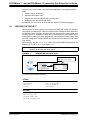
Before starting, copy the Quick Start folder on the dsPICDEM.net Development Kit
Software CD to your c:\ drive (see Figure 3-1).
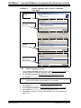
Note:
Files copied from the CD are read only; you will need to change the
attributes of files that need to be edited.
FIGURE 3-1:
DEMONSTRATION CODE FILES
Copy Quick Start folder
from CD to your C:\ drive
The folder should contain these files:
h files:
• defines.h
• delay.h
• lcd.h
• nic_init_param.h
• nic_strings.h
• strings.h
inc files
• device_Fcy.inc
• Si3021_mode.inc
• Si3021_outputs.inc
DS51471A-page 32
2004 Microchip Technology Inc.
Quick Start Program
source files
•
•
•
•
•
•
•
•
•
•
•
•
•
•
1khz.s
2khz.s
bin2dec.c
Dac_Update.c
delay.c
device_config.s
display.s
init_Adc.s
init_Dci.s
init_INTpin.s
init_Ports.s
init_RealTek_NIC.c
init_Si3021.s
init_Spi1.s
3.4.1
1.
2.
3.
4.
•
•
•
•
•
•
•
•
•
•
•
•
•
•
init_Sram.c
init_Timers.s
init_Uart.s
isr_Adc.s
isr_Dci.s
isr_INTpin.s
isr_RealTek_NIC.s
isr_Timers.s
isr_Uart1_tx.s
lcd.c
main.c
TestCAN.c
TestUart1.c
traps.c
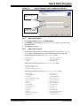
Select a Device
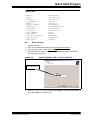
Start MPLAB IDE.
Close any workspace that might be open (File>Close Workspace).
From the Project menu, select Project Wizard.
From the Welcome screen, click the Next> to display the Project Wizard Step
One dialog (see Figure 3-2).
FIGURE 3-2:
PROJECT WIZARD, STEP 1, SELECT A DEVICE
Select dsPIC30F6014
5. Select dsPIC30F6014 as the device and click Next>. The Project Wizard Step
Two dialog displays (see Figure 3-3).
2004 Microchip Technology Inc.
DS51471A-page 33
PICDEM.net™ 1 and dsPICDEM.net 2 Connectivity Dev Board User’s Guide
FIGURE 3-3:
PROJECT WIZARD, STEP 2, SELECT LANGUAGE
TOOLSUITE
Select Microchip C30
Toolsuite
Specify file location for
Assembler
Specify file location for
Compiler
Specify file location for
Object Linker
3.4.2
Select Language Toolsuite
1. From the Active Toolsuite pull-down menu, select Microchip C30 Toolsuite. This
toolsuite includes the compiler, assembler and linker that will be used.
2. Set Toolsuite Contents to MPLAB ASM 30 Assembler (pic30-as.exe).
3. Set Location to: C:\pic30_tools\Bin\pic30-as.exe.
Note:
4.
5.
6.
7.
8.
DS51471A-page 34
C:\ is the drive implemented for this example. The specific location of the
MPLAB C30 compiler may be different on your system.
Reset Toolsuite Contents to MPLAB C30 Compiler (pic30-gcc.exe).
Set Location to: C:\pic30_tools\Bin\pic30-gcc.exe.
Reset Toolsuite Contents to MPLAB LINK30 Object Linker (pic30-Id.exe).
Set Location to: C:\pic30_tools\Bin\pic30-ld.exe.
Click Next> to continue. The Project Wizard Step Three dialog displays (see
Figure 3-4).
2004 Microchip Technology Inc.
Quick Start Program
FIGURE 3-4:
PROJECT WIZARD, STEP 3, NAME YOUR PROJECT
Type a name for your
project...
...and save it in the Project
Directory (C:\Quick Start)
3.4.3
Name Your Project
1. In the Project Name text box, type MyQuickStart.
2. Click Browse... and navigate to C:\Quick Start to place your project in the
Quick Start folder.
3. Click Next> to continue.
3.4.4
Add Files to Project
1. On the Project Wizard Step Four dialog (see Figure 3-5), locate the C:\Quick
Start folder and add all the hex, source and include files to the right side.
Select and add all the files in the Quick Start/h folder:
• defines.h
• delay.h
• lcd.h
• nic_init_param.h
• nic_strings.h
• strings.h
Select and add all the files in the Quick Start/inc folder:
• device_Fcy.inc
• Si3021_mode.inc
• Si3021_outputs.inc
Select and add all the files in the Quick Start/source folder:
•
•
•
•
•
•
•
•
•
•
•
•
•
•
bin2dec.c
Dac_Update.c
delay.c
init_RealTek_NIC.c
init_Sram.c
lcd.c
main.c
TestCAN.c
TestUart1.c
traps.c
1khz.s
2khz.s
device_config.s
display.s
2004 Microchip Technology Inc.
•
•
•
•
•
•
•
•
•
•
•
•
•
•
init_Adc.s
init_Dci.s
init_INTpin.s
init_Ports.s
init_Si3021.s
init_Spi1.s
init_Timers.s
init_Uart.s
isr_Adc.s
isr_Dci.s
isr_INTpin.s
isr_RealTek_NIC.s
isr_Timers.s
isr_Uart1_tx.s
DS51471A-page 35
PICDEM.net™ 1 and dsPICDEM.net 2 Connectivity Dev Board User’s Guide
2. Navigate to the C:\pic30_tools\support\gld folder and add file
p30f6014.gld to include the linker script file in the project.
3. Navigate to the C:\pic30_tools\support\h folder and add file
p30f6014.h to include the header file in the project.
Note:
The linker script file and header file locations for your environment may be
different. The location will depend on where the C30 compiler is installed.
FIGURE 3-5:
PROJECT WIZARD, STEP 4, ADD FILES TO PROJECT
Add the Quick Start files
and dsPIC30F6014
support files to your newly
created project
4. Click Next> to continue. The Project Wizard Summary screen (Figure 3-6)
displays the parameters of your project.
FIGURE 3-6:
PROJECT WIZARD SUMMARY SCREEN
Project named
“MyQuickStart” for
dsPIC30F6014 device will
be saved to C:\Quick Start
5.
DS51471A-page 36
Click Finish.
2004 Microchip Technology Inc.
Quick Start Program
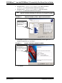
After the project wizard completes, the MPLAB project window shows the project and
all the added files (see Figure 3-7).
FIGURE 3-7:
PROJECT WINDOW
Project window displays the files you
added to your MyQuickStart project
At this point a project and workspace have been created in MPLAB.
MyQuickStart.mcw is the workspace file and MyQuickStart.mcp is the project file.
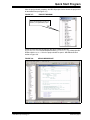
Double-click the main.c file in the project window to open it. MPLAB should look
similar to Figure 3-8.
FIGURE 3-8:
2004 Microchip Technology Inc.
MPLAB WORKSPACE
DS51471A-page 37
PICDEM.net™ 1 and dsPICDEM.net 2 Connectivity Dev Board User’s Guide
3.5
BUILDING THE CODE
In this project, the code is built in two stages. First the source files are compiled into
object files, then the object files are linked.
The MyQuickStart.hex output file contains the data necessary to program the
device. The MyQuickStart.cof output file contains additional information that lets
you debug the code at the source code level.
Before building the program, compiler and linker settings must be specified. These
settings indicate where to find the C library files and where to reserve space for the
extra debug code when the MPLAB ICD 2 (In-Circuit debugger) is used.
3.5.1
Set Project Build Options
The Quick Start project does not explicitly use any libraries, but the C compiler startup
library code is always automatically linked into the project. Use the Project>Build
Options>Project menu to display the Build Options dialog.
1. Select the General tab.
2. Type or browse to the file locations shown in Figure 3-9.
FIGURE 3-9:
BUILD OPTIONS
Let the project know where the
output files will be located
Note:
The library path for your environment may be different. The location will
depend on where you installed the C30 compiler.
3. Select the MPLAB LINK30 tab to display the linker settings.
4. Check Link for ICD2 to tell the linker to reserve space for the debug code used
by the MPLAB ICD 2 In-Circuit Debugger (see Figure 3-10).
5. Click OK.
DS51471A-page 38
2004 Microchip Technology Inc.
Quick Start Program
FIGURE 3-10:
MPLAB LINK30 BUILD OPTIONS
Check Link for ICD2
3.5.2
Build the Project
At this point the project is ready to build.
1. From the Project menu select Build All. The Build Output window displays (see
Figure 3-11).
2. Observe the progress of the build.
3. When the BUILD SUCCEEDED message displays you are ready to program the
device.
FIGURE 3-11:
BUILD OUTPUT
If you experience any problems with the build, double-click the error messages in the
Output window and MPLAB will point to the offending line in the source code. This
should not happen if the files were copied from the dsPICDEM.net Development Kit
CD. Double check all the steps in this section and ensure that you are using the latest
versions of the development tools. The latest upgrades are available on the Microchip
web site (www.microchip.com).
2004 Microchip Technology Inc.
DS51471A-page 39
PICDEM.net™ 1 and dsPICDEM.net 2 Connectivity Dev Board User’s Guide
3.6
DEVICE CONFIGURATION AND PROGRAMMING
After you have built the code you must set up the configuration bits and then connect
the tool you plan to use for programming, running and debugging the code.
Note:
3.6.1
Before proceeding, make sure that the USB driver for the MPLAB ICD 2 has
been installed on your PC (see the MPLAB ICD 2 User’s Guide (DS51331)
for more details regarding the installation of the USB driver).
Set Up Device Configuration
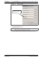
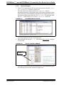
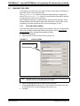
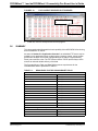
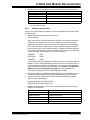
From the Configure menu select Configuration Bits to view the configuration bits and
set up the bits as shown in Figure 3-12. The settings that will most likely need to change
are:
Oscillator Source
Primary Oscillator
Primary Oscillator Mode
XT w/PLL 8x
Watchdog Timer
Disabled
Comm Channel Select
Use PGC/EMUC and PGD/EMUD
FIGURE 3-12:
CONFIGURATION SETTINGS
After building the code and setting the configuration bits, the MPLAB ICD 2 debugger
can be used to run and debug the code on the dsPICDEM.net Demonstration Board.
Follow the instructions in one of the next two sections depending on which tool you are
using.
3.6.2
Enabling the MPLAB ICD 2 Connection
The MPLAB ICD 2 can be used to program and debug the dsPIC30F6014 device
in-circuit on the dsPICDEM.net board.
Note:
Before proceeding, make sure that the USB driver for the MPLAB ICD 2 has
been installed on your PC (see the MPLAB ICD 2 User’s Guide (DS51331)
for details regarding the installation of the USB driver).
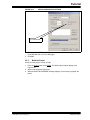
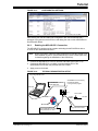
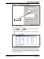
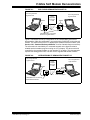
1. Connect the MPLAB ICD 2 to the PC with the USB cable (see Figure 3-13).
2. Connect the MPLAB ICD 2 to modular connector labeled ICD on the
dsPICDEM.net board with the provided short RJ-11 cable.
3. Apply power to the board.
DS51471A-page 40
2004 Microchip Technology Inc.
Quick Start Program
FIGURE 3-13:
dsPICDEM.net™ DEVELOPMENT BOARD CONNECTED TO
MPLAB® ICD 2
PC running MPLAB® IDE
Connect USB cable to PC
dsPICDEM.net™ Connectivity
Development Board
running Quick Start program
J14
ICD
Power Cable
9 VDC
115 VAC
USB Cable
MPLAB® ICD 2
RJ-11 Cable
Connect RJ-11 cable to
MPLAB® ICD 2
Apply power to the board
4. From the Debugger>Select Tool menu, select MPLAB ICD 2 as the debug tool.
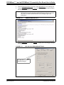
5. From the Debugger menu, select Connect. MPLAB should report that it found the
dsPIC30F6014 as shown in Figure 3-14.
Note:
MPLAB may need to download new firmware if this is the first time the
MPLAB ICD 2 is being used with a dsPIC30F device. Allow it to do so. If
any errors are shown, double-click the error message to get more
information.
FIGURE 3-14:
ENABLING MPLAB ICD 2
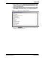
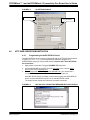
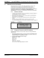
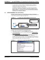
6. From the Debugger menu, select Settings to display the ICD Debugger settings
(see Figure 3-15).
7. On the Program tab, ensure that “Allow ICD 2 to select memories and ranges” is
selected. This setting will speed up programming by addressing only a small part
of the total program memory.
2004 Microchip Technology Inc.
DS51471A-page 41
PICDEM.net™ 1 and dsPICDEM.net 2 Connectivity Dev Board User’s Guide
FIGURE 3-15:
MPLAB ICD 2 DEBUGGER SETTINGS
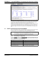
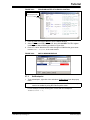
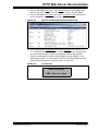
8. Program the part (Debugger>Program). The Output window shows the results of
the programming cycle as shown in Figure 3-16. The part is now programmed
and is ready to run.
FIGURE 3-16:
OUTPUT WINDOW
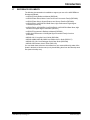
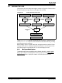
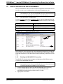
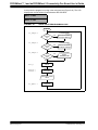
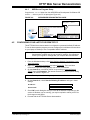
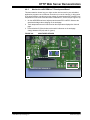
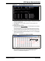
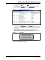
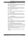
9. Run the code (Debugger>Run). The program initializes and tests the peripherals,
as depicted in Figure 3-17. Note the responses on the dsPICDEM.net board as
the program executes. These responses are indicated along the right side of the
flow chart. The code modules are identified along the left side of the flow chart.
DS51471A-page 42
2004 Microchip Technology Inc.
Quick Start Program
FIGURE 3-17:
PERIPHERAL INITIALIZATION AND TEST PROGRAM FLOW
main.c
START
init_ports.s
Initialize Ports &
W Registers
init_timers.s
Initialize
Timers 1, 2 & 3
LEDS ILLUMINATE
LED2 and LED3 BLINK
Initialize
LCD
lcd.c
Test
SRAM
init_Sram.s
SRAM TEST RESULT DISPLAYS
Display
SRAM FAIL
No
SRAM
Test
Pass?
Yes
Display
SRAM PASS
Initialize & Test
NIC
init_RealTek_NIC.c
NIC TEST RESULT DISPLAYS
Display
LOOPBACK FAIL
No
NIC
Loopback
Pass?
Yes
Display
LOOPBACK PASS
Initialize & Test
CAN
TestCAN.c
CAN TEST RESULT DISPLAYS
Display
LOOPBACK FAIL
No
CAN
Loopback
Pass?
Yes
Display
LOOPBACK PASS
init_uart.s
Initialize & Test
UART1
testuart1.c
UART1 TEST RESULT DISPLAYS
Display
LOOPBACK FAIL
No
UART1
Loopback
Pass?
Yes
Display
LOOPBACK PASS
Initialize
DCI
init_DCI.s
Initialize Si3021
DAA/AFE
init_Si3021.s
FRAME LOCK STATUS DISPLAYS
Display
FAIL Message
init_INTpin.s
init_Spi1.s
init_Adc.s
No
ISOcap
Frame
Lock?
Display
LOCK Message
Initialize INTx
Pins for Interrupt
Initialize
SPI1 Module
Initialize
ADC Module
RUNNING
2004 Microchip Technology Inc.
Yes
RP1 and RP2 VALUES DISPLAY
DS51471A-page 43
PICDEM.net™ 1 and dsPICDEM.net 2 Connectivity Dev Board User’s Guide
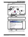
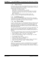
At this point the program is running in the main loop (see Figure 3-18). The LCD
displays the current values of potentiometers RP1 and RP2:
RP1= 3.44v
RP2= 2.14v
FIGURE 3-18:
QUICK START PROGRAM MAIN LOOP
RUNNING
S1 DEPRESSED
isr_INTpin.s
INT1
Interrupt?
(S1)
Yes
Execute OFF-HOOK
and Display Message
No
S2 DEPRESSED
isr_INTpin.s
INT2
Interrupt?
(S2)
Yes
Execute ON-HOOK
and Display Message
No
S3 DEPRESSED
isr_INTpin.s
INT3
Interrupt?
(S3)
Yes
Display
TEMPERATURE
No
delay.c
display.s
bin2dec.c
Delay
200 ms
Call Display
Conversion
Display RP1 & RP2
Values
Dac_Update.c
DS51471A-page 44
Update
Digital Pot
2004 Microchip Technology Inc.
Quick Start Program
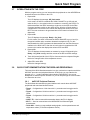
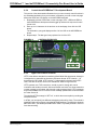
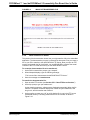
3.7
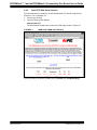
INTERACTING WITH THE CODE
With the program running you can interact with the peripherals on the dsPICDEM.net
board and observe the results on the LCD.
1. Depress S1.
The LCD displays the message: Off_Hook mode.
In this mode, the dsPIC commands the Si3021 DAA/AFE to go off-hook and
seize the line (i.e., the typical routine for a modem to connect to the PSTN). For
this demonstration the dsPIC transmits a single tone to the AFE via the Data
Converter Interface module on the dsPIC device. After the off-hook routine is
completed the LCD reverts to the routine that displays the values of RP1 and
RP2. The tone continues to be generated and can be heard until switch S2 is
depressed.
2. Depress S2.
The LCD displays the message: Ready... On_Hook.
For this routine, the dsPIC commands the Si3021 DAA/AFE to go on-hook (i.e.,
the typical condition when a modem releases the telephone line). For this
demonstration the dsPIC terminates the data transfer from the Data Converter
Interface to the Si3021 AFE. After the on-hook routine is completed the LCD
reverts to the routine that displays the values of RP1 and RP2.
3. Depress S3.
The LCD displays the temperature as measure by sensor U2 followed by the
Ready... On_Hook message and then reverts to the RP1 and RP2 readings.
4. Touch U2 (located just left of the LCD) for a few seconds, then depress S3 again.
Notice the changed value of the temperature sensor.
5. Adjust RP1 and/or RP2.
Notice the changed value(s).
3.8
QUICK START DEMONSTRATION FEATURES AND PERIPHERALS
The intent of the Quick Start demonstration is to give you hands-on experience with the
dsPIC30F processor and peripheral features. At this point, you can examine the
program (main.c) and/or individual code modules in MPLAB IDE. You can set
breakpoints to examine specific activities. Or you can step through the code modules
one instruction at a time.
3.8.1
dsPIC30F Peripheral Features
The Quick Start demonstration program initializes and controls these dsPIC30F
peripherals and associated board functions:
• Timer1 – Configured as a 16-bit timer with 1:1 prescaler used as toggle rate for
LED1.
• Timer2 – Configured as 16-bit timer with a 1:1 prescaler used as toggle rate for
LED2.
• Timer3 – Configured as 16-bit timer with a 1:1 prescaler used as toggle rate for
LED3.
• UART1 TX – Used to transmit demonstration data to the PC for display.
• SPI™ 1 – Used to communicate to the MCP42050 Dual Channel Digital
potentiometer.
• 12-bit ADC – Used to convert multiple analog signals, such as potentiometer and
temperature values (TC1047A temperature sensor).
2004 Microchip Technology Inc.
DS51471A-page 45
PICDEM.net™ 1 and dsPICDEM.net 2 Connectivity Dev Board User’s Guide
• Data Converter Interface – Interfaced to an external Si303x DAA/AFE chipset for
PSTN interface control and monitor.
• INTx pins – Used for detecting switch S1-S3 inputs.
• PORTD pins, RD0-RD15 – Used to interface to 64Kx16 SRAM, 10-base T NIC
and 2x16 LCD.
3.9
DATA AND CONTROL FLOW
3.9.1
Power-up Sequence
Table 3-1 provides more details on the power-up peripheral initialization sequence
illustrated in Figure 3-17.
TABLE 3-1:
Seq
POWER-UP PERIPHERAL INITIALIZATION SEQUENCE
Module or Board
Function
1
2
3
4
Timer1
Timer2
Timer3
2x16 LCD
5
64Kx16 SRAM
6
10-base T NIC
7
UART1
8
Data Converter
Interface (DCI)
9
10
External interrupt
pins INT1-INT3
SPI™ 1
11
12-bit ADC
3.9.2
Initialization Process
Configured to count to 2.2 mS and reset.
Configured to count to 3.95 mS and reset.
Configured to count to 2.2 mS and reset.
Initialization of 2x16 character LCD, via PORTD pins
RD0-RD15.
Initialization and test of 64Kx16 SRAM, via PORTD pins
RD0-RD15. Testing is performed by writing and reading back
a specific incrementing pattern.
Initialization and test of 10-base T NIC, via PORTD pins
RD0-RD15. Testing is performed by performing internal
loop-back tests as supported by the NIC.
The transmitter is configured for interrupt-driven operation at
38400 baud.
Configured for Slave mode. Configured to communicate to the
Si303x DAA/AFE chipset operating in Master mode. Some
DAA/AFE self test routines are executed.
Configured to interrupt on the falling edge and used for
switches S1-S3, respectively.
Configured for communication with MCP42050 Dual Channel
Digital potentiometer.
Configured to continuously sample channels AN3
(temperature sensor U2), AN4 (RP1) and AN5 (RP2).
Main Loop Code Execution
Table 3-2 explains the step-by-step execution sequence of the Main Loop shown in
Figure 3-18
TABLE 3-2:
Seq.
Program Task
1
Check state of variable “hook_status”, which is modified in either INT1, INT2 and
INT3 Interrupt Service Routines.
12-bit ADC collects a sample each from the digital potentiometer RP1 and RP2 and
temperature sensor, U2.
Data obtained from ADC is converted to ASCII for display by UART and LCD.
LCD is updated with Potentiometer RP1 and RP2 values.
SPI 1 transmit RP1 and RP2 values to dual channel digital potentiometer. Monitor of
potentiometer output is via PW0 and PW1 test points on board.
2
3
4
5
DS51471A-page 46
MAIN LOOP CODE EXECUTION SEQUENCE
2004 Microchip Technology Inc.
Quick Start Program
3.9.3
Interrupts Used in the Demonstration Program
3.9.3.1
EXTERNAL INTERRUPTS TO MAIN ROUTINE
External interrupts INT1-INT3 are controlled by switches S1-S3 respectively.
Each switch is monitored by the respective Interrupt pin, INT1-INT3. For each switch
detected the variable “hook_status” is modified in the ISR. The variable “hook_status”
is then monitored in the main loop and based upon the variable state one of three
actions are taken.
3.9.3.2
12-BIT ADC INTERRUPTS
The 12-bit module is configured to continually sample and convert channels AN3
(temperature sensor U2), AN4 (RP1) and AN5 (RP2). When all three signals have been
converted an ADC module based interrupt occurs and the ISR code simply saves off
the converted values to variables defined in data memory. Outside the interrupt this
“raw” data is converted to ASCII by a simple conversion routine and then used by the
UART and LCD display code modules.
3.9.3.3
UART TRANSMIT INTERRUPTS
Approximately every 200 mS, data is transmitted via the UART to the HyperTerminal
session window. The term “data” refers to the following:
• Analog data such as RP1 and RP2 voltages
• Temperature sensor data, U2
3.9.3.4
TIMER1
Timer1 is a 16-bit timer that uses the instruction cycle as its time-base. It is configured
to time out and generate an interrupt every 2.2 milliseconds. The Timer1 Interrupt
Service Routine (ISR) simply toggles LED1 and clears the associated interrupt flag.
3.9.3.5
TIMER2
Timer2 is a 16-bit timer that uses the instruction cycle as its time-base. It is configured
to time out and generate an interrupt every 3.95 milliseconds. The Timer2 Interrupt
Service Routine (ISR) increments a variable, tests bit 9 of this variable and if set toggles
LED2. If LED2 is toggled the ISR resets this same variable to zero. Finally the
associated interrupt flag is cleared.
3.9.3.6
TIMER3
Timer3 is a 16-bit timer that uses the instruction cycle as its time-base. It is configured
to time out and generate an interrupt every 2.2 milliseconds. The Timer3 Interrupt
Service Routine (ISR) increments a variable, tests bit 9 of this variable and if set toggles
LED3. If LED3 is toggled the ISR resets this same variable to zero. Finally the
associated interrupt flag is cleared.
2004 Microchip Technology Inc.
DS51471A-page 47
PICDEM.net™ 1 and dsPICDEM.net 2 Connectivity Dev Board User’s Guide
3.10
SUMMARY
This quick start demonstration program is aimed at getting users more familiar with the
dsPIC peripherals and dsPICDEM.net Development Board functions. In working
through this demonstration you should also become more comfortable with features of
MPLAB IDE and the MPLAB C30 compiler and the use of the MPLAB ICD 2 debugger
with the dsPICDEM.net board.
After working with the Quick Start program you will have:
• Increased your understanding of how the dsPIC30F works with its peripherals.
• Gained a further understanding of how to initialize and control dsPIC30F
peripherals and associated board functions.
• Reduced the learning cycle for getting started with your development using the
dsPIC30F product family.
DS51471A-page 48
2004 Microchip Technology Inc.
dsPICDEM.net™ 1 AND dsPICDEM.net 2
CONNECTIVITY DEVELOPMENT BOARD
USER’S GUIDE
Chapter 4. HTTP Web Server Demonstration
4.1
INTRODUCTION
This chapter describes a sample program that demonstrates Web-based monitoring
and control of an embedded application operating with the CMX-MicroNet TCP/IP
Stack configured for Hyper Text Transfer Protocol (HTTP) Web Server protocol.
4.2
HIGHLIGHTS
Information in this chapter includes:
•
•
•
•
•
•
•
4.3
Demonstration Overview
Demonstration Setup
Configuring your Laptop or Desktop PC
HTTP Web Server Demonstration
Debugging TIPS
Troubleshooting
Using HTTP Web Server in Your Application
DEMONSTRATION OVERVIEW
This demonstration program runs on the dsPIC30F6014 using the CMX-MicroNet
TCP/IP Stack configured for HTTP Web Server protocol to support remote monitoring
and control of the application over an Ethernet connection.
The CMX-MicroNet TCP/IP Stack is designed for optimized use of Flash and RAM
Memory on dsPIC30F devices. This software runs directly on the processor with no
gateways or PCs required. The stack can be run in stand-alone mode or work in
conjunction with an RTOS. This demonstration uses approximately 4.2K instructions in
Flash and 300 bytes in RAM, not including the HTML, java applets and.jpg and.gif
images.
In this demonstration the dsPIC “serves-up” HTML pages to a browser and implements
two basic HTML form methods: GET and POST. The GET and POST methods are
demonstrated in the form of requests from and updates to the HTML page displayed
on a browser. These functions enable you to monitor and change functions on the
dsPICDEM.net board.
The GET method retrieves information from the potentiometers, temperature sensor
and switches to illustrate monitoring functionality. The POST method uploads
information to the LCD and LEDs on the board to illustrate control and updating
functionality. For this demonstration the HTML page served-up by the dsPIC device is
stored in the Flash Program Memory. Alternatively, the dsPICDEM.net board provides
a 24LC515 Serial I2C EE 64 Kbyte Memory device that can be used to store the HTML
pages.
2004 Microchip Technology Inc.
DS51471A-page 49
PICDEM.net™ 1 and dsPICDEM.net 2 Connectivity Dev Board User’s Guide
4.4
DEMONSTRATION SETUP
4.4.1
Equipment Requirements
The HTTP Web Server demonstration requires the following equipment:
• dsPICDEM.net Development Board Kit with dsPIC30F6014 Plug-in-Module (PIM)
• CAT-5 crossover cable (or standard Ethernet cable and access to a network or
hub)
• MPLAB IDE Integrated Development Environment
• MPLAB ICD 2 In-Circuit Debugger
• Laptop or Desktop PC with RS-232 serial port or USB port for connecting to the
MPLAB ICD 2 In-Circuit Debugger
• RJ-11 phone cable for connecting the MPLAB ICD 2 to the dsPICDEM.net board
4.4.2
Equipment Setup
Connect the dsPICDEM.net board to your PC or laptop as shown in Figure 4-1.
FIGURE 4-1:
WEB SERVER DEMONSTRATION SETUP
PC running MPLAB®
IDE and Internet
Explorer
USB Port
Connect board to PC with
CAT-5 crossover cable
dsPICDEM.net™ Connectivity
Development Board running
web server demonstration
Ethernet
connection
J14
Power Cable
J15
ICD
Connect MPLAB® ICD 2
to PC with USB cable
ICD 2
9 VDC
115 VAC
Apply power to board
Connect MPLAB® ICD 2 to
board with RJ-11 phone cable
1. Connect the MPLAB ICD 2 to your PC with the USB cable.
2. Using the short RJ-11 phone cable, connect the MPLAB ICD 2 to RJ-11 modular
connector ICD on the board.
3. Connect one end of the supplied CAT-5 crossover cable to RJ-45 modular
connector J15 on the board and the other end to the Ethernet network card on
the PC or Laptop.
4. Connect the dsPICDEM.net power cable to the power input connector (J14).
DS51471A-page 50
2004 Microchip Technology Inc.
HTTP Web Server Demonstration
4.4.3
WEB Server Program Setup
Copy the WEB Server folder from the dsPICDEM.net Development Kit Software CD
to the C:\ drive on your PC or laptop (see Figure 4-2).
FIGURE 4-2:
WEB SERVER DEMONSTRATION CODE
Copy WEB Server folder from
CD to your C:\ drive
4.5
CONFIGURING YOUR LAPTOP OR DESKTOP PC
This HTTP Web Server demonstration is configured to operate with a Static IP address.
To run the demonstration program you must configure the local Network Connections
on your laptop or Desktop to use a compatible Static IP address.
Note:
Before reconfiguring your network connection settings for this
demonstration, make a note of your current PC settings. You will want to
restore your original PC settings after you complete this demonstration.
To reconfigure your network connections, follow these steps:
1. From the Windows desktop, click Start>Settings>Network Connections> Local
Area Connection.
2. Right-click Local Area Connection and select Properties. The Local Area
Connection Properties dialog displays your current connections.
3. On the General tab, scroll down the list of connections to Internet Protocol
TCP/IP, then click Properties. The Internet Protocol (TCP/IP) Properties dialog
displays, as shown in Figure 4-3.
Note:
Record your current settings so you can restore them later.
4. On the General tab, check Use the following IP address: and type in these
settings:
IP Address:
216
. 233
.
5
Subnet mask:
255
. 255
. 255
.
32
.
0
5. Check OK in each dialog box until you close all the windows. Depending on the
version of Windows you are running, you may be required to reboot your PC for
the changes to take effect.
6. Proceed with the HTTP Web Server demonstration.
2004 Microchip Technology Inc.
DS51471A-page 51
PICDEM.net™ 1 and dsPICDEM.net 2 Connectivity Dev Board User’s Guide
FIGURE 4-3:
IP SETTINGS DIALOG
Check this option
Type IP address
4.6
HTTP WEB SERVER DEMONSTRATION
4.6.1
Programming the dsPIC30F6014 Device
The dsPIC30F6014 device must be programmed with the HTTP Web demonstration
program (webdemo.hex). If you have previously loaded this program on a
dsPIC30F6014 device you can proceed directly to Section 4.6.2 “Start HTTP Web
Server Session”.
1. Apply power to the board. The green POWER LED illuminates.
2. Launch MPLAB IDE on your PC. From the Configure menu, choose Select
Device, then select dsPIC30F6014.
3. Select Programmer>Select Programmer>MPLAB ICD 2. You should see a
connection message in the output window, as shown in Figure 4-4.
If the MPLAB ICD 2 does not initially connect and recognize the dsPIC30F6014
device, click the MPLAB ICD 2 puck icon on the MPLAB IDE toolbar.
The output window should then indicate a successful connection.
FIGURE 4-4:
DS51471A-page 52
MPLAB ICD 2 CONNECTION MESSAGE WITH dsPIC30F6014
2004 Microchip Technology Inc.
HTTP Web Server Demonstration
4. From the MPLAB IDE File menu, select Import. Browse to the C:\WEB Server
directory where you saved the webdemo.hex file, select it and click Open.
5. From the MPLAB IDE Configure menu, select Configuration Bits and verify the
device configuration settings shown in Figure 4-5.
FIGURE 4-5:
SETTING CONFIGURATION BITS IN MPLAB IDE
6. From the MPLAB IDE Programmer menu select Program. The webdemo.hex
file downloads to the dsPIC30F6014. The Output Window records the process
as it occurs and indicates completion by displaying “MPLAB ICD 2 Ready”.
7. Remove the MPLAB ICD 2 cable from the board then press “RESET” on the
demonstration board to run the program. The LCD on the dsPICDEM.net board
indicates that the program is running, as shown in Figure 4-6.
FIGURE 4-6:
LCD DISPLAY
CMX-MicroNet
WEB Server Demo
2004 Microchip Technology Inc.
DS51471A-page 53
PICDEM.net™ 1 and dsPICDEM.net 2 Connectivity Dev Board User’s Guide
4.6.2
Start HTTP Web Server Session
This demonstration is intended to run with Windows 98, NT, and XP using Internet
Explorer 5 or 6 or Netscape 4.7.
1. Launch your browser.
2. Type the following URL address:
http://216.233.5.31
The dsPIC30F6014 Web Server returns the HTML page shown in Figure 4-7.
FIGURE 4-7:
WEB PAGE FROM dsPIC30F6014
If you encounter a connection problem refer to Section 4.8 “Troubleshooting”.
DS51471A-page 54
2004 Microchip Technology Inc.
HTTP Web Server Demonstration
4.6.3
Monitor the dsPICDEM.net™ Development Board
This demonstration shows how you might monitor devices used in your embedded
application program over an Ethernet connection (or over the internet). In this portion
of the demonstration you will monitor the voltage on potentiometers RP1 and RP2, the
temperature on sensor U12 and the status of switches S1, S2 and S3 (see Figure 4-8).
1. On the dsPICDEM.net board, adjust potentiometers RP1 and RP2. Observe the
associated voltage value changing on the web page.
2. Touch temperature sensor U2 and monitor the temperature displayed on the web
page.
3. Press switches S1-S3 and observe the switch indicators on the web page
change between Off (red) and On (green).
FIGURE 4-8:
MONITORED DEVICES
POTS RP1-RP2
SWITCHES S1-S3
TEMPERATURE SENSOR U2
2004 Microchip Technology Inc.
DS51471A-page 55
PICDEM.net™ 1 and dsPICDEM.net 2 Connectivity Dev Board User’s Guide
4.6.4
Control the dsPICDEM.net™ Development Board
This portion of the demonstration illustrates how you can remotely control functions in
an embedded application from your browser. Information you enter on the web page
affects the LEDs and LCD display on the dsPICDEM.net board.
1. Repeatedly click the LEDs button on the web page. LED1, LED2 and LED3 on
the dsPICDEM.net development board toggle up and down in sequence for each
mouse click.
2. Enter up to 16 characters in the text box on the web page, then click the LCD
button.
The information you typed displays as line 2 of the LCD on the dsPICDEM.net
board.
3. Repeat step 2. The last typed entry replaces line 2 of the LCD.
FIGURE 4-9:
CONTROLLED DEVICES
LEDS 1-3
INFORMATION TYPED ON WEB PAGE
DISPLAYS ON LCD
4.6.5
Hyper Text Transfer Protocol
HTTP is the defacto standard for transferring World Wide Web documents, although it
is designed to be extensible to almost any document format. HTTP Version 1.1 is
documented in RFC 2068. HTTP Version 1.0 (deprecated) is documented in RFC
1945. See also the W3C’s work on the standard at: www.w3.org/Protocols/.
HTTP operates over TCP connections, usually to port 80, though this can be
overridden and another port used. After a successful connection, the client transmits a
request message to the server, which sends a reply message back. HTTP messages
are human-readable. An HTTP server can be manually operated with a command such
as Telnet Server 80.
The simplest HTTP message is "GET url”, to which the server replies by sending the
named document.
In HTML, you can specify two different submission methods for a form. The method is
specified inside a form element, using the METHOD attribute. The difference between
METHOD="GET" (the default) and METHOD="POST" is primarily defined in terms of
form data encoding.
DS51471A-page 56
2004 Microchip Technology Inc.
HTTP Web Server Demonstration
4.7
DEBUGGING TIPS
Use a packet sniffer to monitor all the transmitted frames and observe exactly what is
going on in real-time (see Figure 4-10). A packet sniffer can be used with the PC-side
TCP/UDP client/server test programs that are included with the MicroNet software. A
number of good packet sniffers are available as freeware.
Freeware Packet Sniffers for Windows include:
•
•
•
•
•
AnalogX PacketMon (www.analogx.com)
Anasil (www.sniff-tech.com)
CommView (www.tamosoft.com)
Ethereal (www.ethereal.com)
Sniff'em (www.sniff-em.com)
Commercially available packet sniffers include:
• Klos Technologies' SerialView, PacketView (www.klos.com)
• Windows Packet sniffing library for C#, C++, VB (www.packet-sniffing.com)
For additional information on packet sniffers, refer to:
www.robertgraham.com/pubs/sniffing-faq.html
FIGURE 4-10:
2004 Microchip Technology Inc.
ETHEREAL FREEWARE PACKET SNIFFER
DS51471A-page 57
PICDEM.net™ 1 and dsPICDEM.net 2 Connectivity Dev Board User’s Guide
4.8
TROUBLESHOOTING
The HTTP Web Server program has been tested on a dsPICDEM.net connectivity
board like the one you have received. No problems have been encountered (hence
none expected when you run the demonstration).
The Java applets used in the HTTP Web Server program have been tested with
Internet Explorer 5 and 6 and Netscape 4.7 from Windows 98, NT, and XP platforms.
Depending on the Java settings in your browser, you may experience the following
error message when the browser begins communication with the dsPIC30F-based
Web Server and attempts to load the Java applet:
Loading class dsPICDEMO
Exception:java.lang.NullPointerException
To remedy this error condition, use this procedure:
Note:
The exact steps may be slightly different depending on the version of Windows, the browser type and browser version you are using.
1. Open the Internet Properties (XP) dialog box.
From your browser select Tools>Internet Options.
From Windows select Start>Settings>Control Panel>Internet
Options>Advanced.
Ensure that Java console enabled (requires restart) is selected (see
Figure 4-11). Click OK and allow the browser to restart.
FIGURE 4-11:
DS51471A-page 58
BROWSER JAVA SETTINGS
2004 Microchip Technology Inc.
HTTP Web Server Demonstration
Next, go to Control Panel and select the Java Plug-in application. Open this application
and select the Cache tab. Ensure the “Enable Caching” box is deselected. Once
complete click on the Apply and close this control panel.
Retry the browser refresh function and see if the entire HTML page is now displayed
correctly.
FIGURE 4-12:
4.9
JAVA PLUG-IN BROWSER SETTINGS
USING HTTP WEB SERVER IN YOUR APPLICATION
Operating the dsPIC30F with the CMX MicroNet TCP/IP stack gives you the ability to
send data across the Internet. However, you must decide how to use it in your design.
If you are simply looking for an interactive method of monitoring real time values as they
are changing within your target device, you may want to utilize the HTTP protocol and
server already developed. By setting up a series of URLs or “links”, you can have the
HTTP module format the information in the form of HTML files.
If you require a more efficient or a secure form of interaction, you could set up a
proprietary method of communication and deliver it within the payload of the TCP
packet itself. A Windows application could be created in order to communicate, interact
and manage a group of your devices on the Net. One step further may be to give the
ability of the devices themselves to interact with each other.
2004 Microchip Technology Inc.
DS51471A-page 59
PICDEM.net™ 1 and dsPICDEM.net 2 Connectivity Dev Board User’s Guide
NOTES:
DS51471A-page 60
2004 Microchip Technology Inc.
dsPICDEM.net™ 1 AND dsPICDEM.net 2
CONNECTIVITY DEVELOPMENT BOARD
USER’S GUIDE
Chapter 5. FTP Server Demonstration
5.1
INTRODUCTION
This chapter describes a sample program that demonstrates remote monitoring and
control of an embedded application using File Transfer Protocol (FTP) communication.
5.1
HIGHLIGHTS
Information in this chapter includes:
•
•
•
•
•
5.2
Application Overview
Demonstration Setup
Configuring your Laptop or Desktop PC
FTP Server Demonstration
Summary
APPLICATION OVERVIEW
This demonstration program illustrates file transfers between an embedded application
on the dsPIC30F6014 and a remote computer. The embedded application uses the
CMX-MicroNet TCP/IP Stack configured as an FTP Server. The FTP server
“associates” system application data with a virtual file system implemented in the
dsPIC Flash memory.
A typical dsPIC30F FTP application allows data files produced by the dsPIC device and
stored in the virtual file system to be retrieved remotely for such tasks as data logging,
inventory control, performance analysis, and more, on the remote computer system.
Some applications may update Program Flash on a remote dsPIC device from a central
server location. In other applications, FTP activity may execute on a scheduled basis
using automatic error detection/correction to ensure that data is properly transmitted
and received.
CMX-MicroNet FTP Server is fully compliant with Internet Engineering Task Force
(IETF) and Request for Comments (RFC) standards and supports Windows-, DOS-,
UNIX- and Linux-based FTP clients. For detailed information on these standards, refer
to: www.ietf.org/ and www.faqs.org/rfcs/, respectively.
This sample application demonstrates two main activities supported by the
dsPIC30F6014 FTP Server:
• Retrieving a file on the FTP server from an FTP client
• Transmitting data to the FTP server from an FTP client
This demonstration is set up to run with a Microsoft Windows FTP client or at the
command prompt.
2004 Microchip Technology Inc.
DS51471A-page 61
PICDEM.net™ 1 and dsPICDEM.net 2 Connectivity Dev Board User’s Guide
5.3
DEMONSTRATION SETUP
5.3.1
Equipment Requirements
This demonstration requires the following equipment:
•
•
•
•
•
dsPICDEM.net Development Board Kit with dsPIC30F6014 Plug-in-Module (PIM)
Crossover Cable (or standard Ethernet cable and access to a network or hub)
MPLAB IDE Integrated Development Environment
MPLAB ICD 2 In-Circuit Debugger
Laptop or Desktop PC with RS-232 serial port or USB port for connecting to the
MPLAB ICE 2 In-Circuit Emulator
• RJ-11 phone cable for connecting the MPLAB ICD 2 to the dsPICDEM.net board.
5.3.2
Equipment Setup
Connect the dsPICDEM.net board to your PC or laptop as shown in Figure 5-1.
FIGURE 5-1:
FTP SERVER DEMONSTRATION SETUP
PC running MPLAB® IDE
and DOS Command
Prompt
USB Port
Connect board to PC with
CAT-5 crossover cable
dsPICDEM.net™ Connectivity
Development Board running
FTP Ssrver demonstration
Ethernet
connection
J14
Power Cable
J15
ICD
9 VDC
115 VAC
Apply power to board
Connect MPLAB® ICD 2
to PC with USB cable
Connect MPLAB® ICD 2
to board with RJ-11 phone
cable
1. Connect the MPLAB ICD 2 to your PC with the USB cable.
2. Using the short RJ-11 phone cable, connect the MPLAB ICD 2 to RJ-11 modular
connector ICD on the board.
3. Connect one end of the supplied CAT-5 crossover cable to RJ-45 modular
connector J15 on the board and the other end to the Ethernet network card on
the PC or Laptop.
4. Connect the dsPICDEM.net power cable to the power input connector (J14).
DS51471A-page 62
2004 Microchip Technology Inc.
FTP Server Demonstration
5.3.3
FTP Server Program Setup
Copy the FTP Server folder from the dsPICDEM.net Development Kit Software CD
to the C:\ drive on your PC or laptop (see Figure 5-2).
FIGURE 5-2:
FTP SERVER DEMONSTRATION CODE
Copy FTP Server folder from
CD to your C:\ drive
5.4
CONFIGURING YOUR LAPTOP OR DESKTOP PC
The FTP server demonstration is configured to operate with a Static IP address. To run
the sample program you must configure the local network connections on your laptop
or desktop computer to use a compatible Static IP address.
Note:
5.4.1
Before you reconfigure your network connection settings for this sample
program, make a note of your current PC settings. You will want to restore
your original PC settings after you complete the demonstration.
Network Connections
To reconfigure your network connections, follow these steps:
1. From the Windows desktop, click Start>Settings>Network Connections> Local
Area Connection.
2. Right-click Local Area Connection and select Properties. The Local Area
Connection Properties dialog displays your current connections.
3. On the General tab, scroll down the list of connections to Internet Protocol
TCP/IP, then click Properties. The Internet Protocol (TCP/IP) Properties dialog
displays, as shown in Figure 5-3. Make a note of your current settings so you
can restore them later.
4. On the General tab, check Use the following IP address: and type in these
settings:
IP Address:
216
. 233
.
5
Subnet mask:
255
. 255
. 255
.
32
.
0
5. Check OK in each dialog box until you close all the windows. Depending on the
version of Windows you are running, you may be required to reboot your PC for
the changes to take effect.
6. Proceed with the FTP Server demonstration.
2004 Microchip Technology Inc.
DS51471A-page 63
PICDEM.net™ 1 and dsPICDEM.net 2 Connectivity Dev Board User’s Guide
FIGURE 5-3:
IP SETTINGS DIALOG
Check button
5.5
Type IP address
FTP SERVER DEMONSTRATION
5.5.1
Programming the dsPIC30F6014 Device
This exercise requires that the dsPIC30F6014 device be programmed with the FTP
demonstration program (ftpdemo.hex). If you have previously loaded this program on
a dsPIC30F6014 device you can proceed directly to Section 5.5.2 “Start FTP Server
Session”.
1. Apply power to the board. The green POWER LED illuminates.
2. Launch MPLAB IDE on your PC. From the Configure menu, choose
Select Device, then select dsPIC30F6014.
3. From the MPLAB IDE Debugger menu, choose Select Tool, then select
MPLAB ICD 2. You should see a connection message in the output window, as
shown in Figure 5-4.
DS51471A-page 64
2004 Microchip Technology Inc.
FTP Server Demonstration
If the MPLAB ICD 2 does not initially connect and recognize the dsPIC30F6014
device, click the MPLAB ICD 2 puck icon on the MPLAB IDE toolbar.
The output window should then indicate a successful connection.
FIGURE 5-4:
MPLAB ICD 2 CONNECTION MESSAGE WITH dsPIC30F6014
4. From the MPLAB IDE File menu, select Import. Browse to c:\FTP Server and
open ftpdemo.hex.
5. From the MPLAB IDE Configure menu select "Configuration Bits” and verify the
device configuration settings shown in Figure 5-5.
FIGURE 5-5:
FTP SERVER CONFIGURATION BITS SETTINGS
6. From the MPLAB IDE Debugger menu select Program. The ftpdemo.hex file
downloads to the dsPIC30F6014. The Output Window records the process as it
occurs and indicates completion by displaying "MPLAB ICD 2 Ready”.
7. Press <F6> to reset the program, then press <F9> to run the program. The LCD
on the dsPICDEM.net board indicates that the program is running, as shown in
Figure 5-6.
FIGURE 5-6:
LCD DISPLAY FOR FTP DEMONSTRATION
CMX-MicroNet
FTP Server Demo
2004 Microchip Technology Inc.
DS51471A-page 65
PICDEM.net™ 1 and dsPICDEM.net 2 Connectivity Dev Board User’s Guide
5.5.2
Start FTP Server Session
After programming the demonstration into the dsPIC30F6014, follow these steps:
1. If CMX-MicroNet FTP Server is not running, press <F6> (Reset) followed by
<F9> (Run).
2. From Windows, open a DOS command session.
3. From the command line prompt, type “ftp 216.233.5.31” to connect to the
dsPIC30F6014 FTP Server.
When the connection is made you will be prompted for your user name and
password.
4. For the user name type “cmx”.
5. When prompted for the password, type “password”.
Note:
Both the user and password are case-sensitive. Be sure both entries are
lower case.
Upon successful sign-on you will have connected to the FTP Server running on
the dsPIC30F6014 device. You will see a transaction sequence similar to that
shown in Figure 5-7.
FIGURE 5-7:
LOG ON FTP SERVER SESSION
Successful connection
Successful sign-on
This screen shows when the connection is made and when the user is successfully logged on. This program only uses commands necessary to receive files
from and send files to the dsPIC30F device. For information on the command set
supported by CMX-MicroNet FTP Server, refer to the “FTP FUNCTIONS” section
of the CMX-MicroNet TCP/IP STACK Manual.
DS51471A-page 66
2004 Microchip Technology Inc.
FTP Server Demonstration
5.5.3
Receive File From FTP Server
This portion of the demonstration shows how you might retrieve a file from the FTP
Server virtual file system in dsPIC30F6014 memory.
1. At the ftp> prompt, type “dir”.
2. The FTP Server returns a listing of the files in its virtual file system, as shown in
Figure 5-8.
FIGURE 5-8:
RECEIVING A FILE FROM THE FTP SERVER
3. At the next ftp> prompt, type get index.htm.
As the file downloads, the DOS screen displays status milestones: command
received (200), file ready to send (150), and file transferring (226).
4. When the file transfer is complete, the status displays the number of bytes
transferred, how long it took, and the transfer rate achieved. At the next ftp>
prompt, type “quit” to close the FTP session, but leave the DOS session running.
5. In Windows, locate and view the transferred file using a graphics program (see
Figure 5-9). This file is located in the directory from which you ran the DOS
command FTP session (c:\).
2004 Microchip Technology Inc.
DS51471A-page 67
PICDEM.net™ 1 and dsPICDEM.net 2 Connectivity Dev Board User’s Guide
FIGURE 5-9:
5.5.4
IMAGE OF TRANSFERRED FILE
Send a File to FTP Server
This portion of the demonstration shows how you might transfer a file to the embedded
application. The demonstration process is conducted in three parts. First you create a
file on your PC to transfer to the dsPIC30F6014 FTP Server. Next you open an FTP
session and transfer the file. And finally, you use MPLAB IDE to examine the actual
contents of the FTP virtual file memory on the dsPIC30F6014 device.
To create the demonstration file to be transferred:
1. At the DOS command line prompt, type “notepad”.
2. When Notepad displays, type the following message:
“This is a test file to demonstrate the dsPIC30F6014 FTP Server.”
3. Save the message as c:\testdemo.txt.
To transfer the demonstration file:
1. Open another FTP session (see Section 5.5.2 “Start FTP Server Session”).
2. At the ftp> prompt, type “put testdemo.txt”.
As the transfer progresses, milestones are displayed sequentially. When the file
transfer is complete, the status displays the number of bytes transferred, how
long it took, and the transfer rate achieved.
3. At the next ftp> prompt, type “dir” to verify that the file is now in the FTP server
virtual data memory. The listing shows that the file is included, as shown in
Figure 5-10.
DS51471A-page 68
2004 Microchip Technology Inc.
FTP Server Demonstration
FIGURE 5-10:
FTP SEND DEMONSTRATION SESSION
4. At the ftp> prompt, type “quit” to end the FTP session. Then type “exit” to close
the DOS command prompt.
5. Go to MPLAB IDE and press <F5> to halt the FTP Server program in the
dsPIC30F6014.
To examine FTP Server memory:
1. In MPLAB IDE select View > File Registers. The File Registers window displays
the contents of the FTP Server virtual file.
The information displayed in red represents new data in FTP Server memory.
Information related to this demonstration starts around address location 0x850.
2. Page down the File Registers window to until you see the values displayed in red.
Examine the ASCII data to look for the file name (testdemo.txt) in the ASCII
area, as shown in Figure 5-11.
FIGURE 5-11:
FTP VIRTUAL FILE DIRECTORY ENTRY
Shows testdemo.txt file
3. Next, scroll down to the next block of red data (approximately at address
0x2000-0x2100). Examine the ASCII area to find the content of the
testdemo.txt file, as shown in Figure 5-12.
2004 Microchip Technology Inc.
DS51471A-page 69
PICDEM.net™ 1 and dsPICDEM.net 2 Connectivity Dev Board User’s Guide
FIGURE 5-12:
FILE CONTENT RECEIVED BY FTP SERVER
Content of testdemo.txt
file
4. In MPLAB, close the workspace and exit the program.
5.6
SUMMARY
This demonstration has illustrated the basic capability of the dsPIC30F6014 functioning
as an embedded FTP Server.
As stated in Section 5.2 “Application Overview” an embedded FTP server may be
suitable in such applications such as data logging, inventory control, remote system
performance analysis and remote reprogramming of the dsPIC Program Memory
Flash, just to mention a few. The FTP Server uses the TCP/IP protocol layer, which
ensures an ordered reliable delivery of the data.
The Program Memory Flash and Data RAM resources requirements for the
CMX-MicroNet Stack is presented in Table 5-1.
TABLE 5-1:
RESOURCES FOR THE CMX-MICRONET STACK
Flash
UDP/IP + Core
4470 bytes
TCP/IP + Core
7827 bytes
UDP/TCP/IP + Core
8685 bytes
PPP
6681 bytes
Modem
447 bytes
HTTP Server
3888 bytes
Virtual File
885 bytes
Ethernet
2652 bytes
DHCP Client
2202 bytes
FTP Server
3657 bytes
TFTP Client
723 bytes
BOOTP
684 bytes
SMTP
1918 bytes
Utility
1314 bytes
RAM (not including buffer sizes)
DS51471A-page 70
UDP/SLIP
56 bytes
TCP/HTTP/PPP
304 bytes
Ethernet
38 bytes
2004 Microchip Technology Inc.
dsPICDEM.net™ 1 AND dsPICDEM.net 2
CONNECTIVITY DEVELOPMENT BOARD
USER’S GUIDE
Chapter 6. V.22bis Soft Modem Demonstration
6.1
INTRODUCTION
This chapter describes the dsPIC30F Soft Modem demonstration running on the
dsPICDEM.net Development Board. The demonstration software is a subset of the
dsPIC30F data modem library offered by Microchip. The dsPIC30F data modem library
is composed of ITU-T compliant algorithms for V.21, V.22, V.22bis, V.23, V.32 and
V.32bis modem recommendations and Bell standard 103. The dsPIC30F data-modem
included as part of the dsPICDEM.net Connectivity Development Board and
demonstrated in this section supports V.22bis and all lower data pump modulations.
Full source code for V.22bis and lower data pump modulations is provided on the
dsPICDEM.net Development Kit Software CD. V.32bis is not part of this demonstration
package but is available for purchase.
For detailed information on the soft modem refer to the dsPIC30F Soft Modem User’s
Guide provided on the dsPICDEM.net Development Kit Software CD.
6.1
HIGHLIGHTS
Information covered in this chapter includes:
•
•
•
•
•
•
•
•
•
6.2
Demonstration Overview
Demonstration Configurations
Demonstration Procedures
Reprogramming the dsPIC30F6014
Description of dsPIC30F Soft Modem
dsPIC30F Soft Modem AT Command Set
Troubleshooting the Connection
Regulatory Compliance Reference Information
ITU-T Specifications
DEMONSTRATION OVERVIEW
This demonstration illustrates the ability of the dsPIC30F Soft Modem to connect to
another modem for transmitting and receiving data over the PSTN. The demonstration
program implements real-time ITU-T V.22bis Transmit and Receive Data Pump
Modulations. For specific information related to key features and performance metrics
for the dsPIC30F Soft Modem see Section 6.6 “Description of dsPIC30F Soft
Modem”.
2004 Microchip Technology Inc.
DS51471A-page 71
PICDEM.net™ 1 and dsPICDEM.net 2 Connectivity Dev Board User’s Guide
Some possible applications implied by this demonstration include:
•
•
•
•
•
•
•
•
•
6.3
POS Terminals
Set Top Boxes
Drop Boxes
Fire Panels
Internet-enabled home security systems
Internet-connected power, gas and water meters
Internet-connected vending machines
Smart Appliances
Industrial Monitoring
DEMONSTRATION CONFIGURATIONS
The soft modem demonstration is set up to run either as a pair of dsPIC30F devices
running the soft modem and connected end-to-end, or as a dsPIC30F device
communicating with a remote terminal equipped with a standard reference modem.
The LEDs and switches on the dsPICDEM.net board are not used for the soft modem
demonstration.
6.3.1
Equipment Requirements
The soft modem demonstration requires the following equipment:
• dsPICDEM.net Development Board for originate/answer modem
• dsPICDEM.net Development Board or standard reference modem for
answer/originate modem
• PC or laptop for configuring and controlling dsPIC30F soft modem(s) via AT
commands
• PC or laptop for configuring and controlling standard reference modem via AT
commands
• Analog phone line for each originate and answer modem
• RJ-11 phone cable for each dsPICDEM.net board and standard reference modem
(not provided)
Note:
6.3.2
Connect dsPICDEM.net to an analog line only. Using a non-analog line
(e.g., digital, PBX Multi line) may damage the modem.
Selecting the Demonstration Configuration
Figure 6-1 illustrates the set-up configuration for operating the end-to-end soft modem
demonstration. This configuration requires the modem software on both
dsPICDEM.net boards. The soft modem is controlled by AT commands entered on the
Windows HyperTerminal (or suitable alternative terminal emulator) running on the PC
or Laptop. This demonstration requires two analog phone lines, one each for the
originate and answer modems.
DS51471A-page 72
2004 Microchip Technology Inc.
V.22bis Soft Modem Demonstration
FIGURE 6-1:
END-TO-END DEMONSTRATION SET UP
PC running Windows
HyperTerminal
RS232
PC running Windows
HyperTerminal
Analog
Telephone
Exchange
or TAS
RS232
RJ-11
dsPICDEM.net™ Connectivity
Board running Soft Modem
Figure 6-2 illustrates the set-up configuration for the interoperability soft modem
demonstration. With this configuration, one terminal is the dsPIC30F running the soft
modem. The other terminal is a PC or laptop with a standard reference modem. (See
Section 6.8.1 “Standard Reference Modems” for a list of tested reference modems).
The soft modem is controlled by AT commands entered on the HyperTerminal or
suitable terminal emulator program running on a PC or laptop. The other terminal is
controlled by the terminal emulator on the opposite PC or laptop. This demonstration
requires two analog phone lines, one each for the originate and answer modems.
FIGURE 6-2:
INTEROPERABILITY DEMONSTRATION SET UP
PC running Windows
HyperTerminal
RS232
PC running Windows
HyperTerminal
Analog
Telephone
Exchange
or TAS
RS232
RJ-11
Standard
Reference Modem
dsPICDEM.net™ Connectivity
Board with Soft Modem
2004 Microchip Technology Inc.
DS51471A-page 73
PICDEM.net™ 1 and dsPICDEM.net 2 Connectivity Dev Board User’s Guide
6.4
DEMONSTRATION PROCEDURES
Follow these steps to exercise the soft modem functionality in real time. The
dsPIC30F6014 device plugged into the dsPICDEM.net board has been
pre-programmed with the V.22bis data-modem for this demonstration. If the
demonstration program has been replaced by another application, you will need to
reprogram the dsPIC30F6014 (see Section 6.5 “Reprogramming the
dsPIC30F6014” for instructions on programming the soft modem into the dsPIC).
6.4.1
Initialize the Hardware
1. Configure the demonstration for end-to-end operation, as shown in Figure 6-1,
or interoperability, as shown in Figure 6-2.
2. Make sure the 2x2 shunts on J17 and J19 are inserted in vertical alignment
(perpendicular to the LCD display)
3. Apply power to the dsPICDEM.net Board(s) and/or the standard reference
modem.
4. Press and release the RESET switch located to the right of the LCD.
The LCD acknowledges that the soft modem is initialized, as shown in Figure 6-3
FIGURE 6-3:
LCD DISPLAY
dsPIC30F V.22bis
Soft-Modem Demo
6.4.2
Configure the Terminal for dsPIC30F Soft Modem
These procedures assume, but do not require, that you are using the Windows
HyperTerminal.
1. Start HyperTerminal on both PCs. If you are set up for interoperability and are
using a standard reference modem on one terminal, consult the modem user
manual for specifics on configuring the modem.
2. Configure HyperTerminal with these settings:
Bits per second = 19200
Data bits = 8
Parity = None
Stop bits = 1
Flow Control = Hardware
Set the Comm Channel appropriately for each PC.
DS51471A-page 74
2004 Microchip Technology Inc.
V.22bis Soft Modem Demonstration
3. Execute these AT commands on each HyperTerminal and note the response.
Command*
Response
AT<ENTER>
OK
AT&F<ENTER>
OK
ATX0
OK
ATS0=1
OK
*Refer to Section 6.7 “dsPIC30F Soft Modem AT Command Set” for descriptions of
AT commands supported.
6.4.3
Initiate Communication
At this point, the dsPIC30F Soft Modem is ready to establish a dial connection with
another modem.
1. Initiate dialing with the following AT command:
ATD<dial string>
where <dial string> indicates the telephone number of the remote soft modem.
By default, ‘auto answer after one ring’ is enabled. The remote soft modem
answers the call after one ring and connects in V.22bis and V.42 (LAPM) Mode.
ITU-T Recommendation V.42 contains a High Level Data Link Control (HDLC)
protocol referred to as Link Access Procedure for Modems (LAPM) and defines
error-correcting protocols for modems The following result codes are displayed
on both the Hyper Terminals upon a successful connection.
CARRIER
2400
PROTOCOL
LAPM
CONNECT
19200
You should hear the call negotiation and training sequence on the call progress
speaker. If you are using a standard reference modem on one terminal, the connection message transmitted and displayed on the PC may be slightly different
but should present this same basic information. See Section 6.8.6 “Response
Messages for Successful Modem Connections” for an example of a
connection message provided by a USR 5686E type modem.
2. With the two modems connected, test data transfer by typing information on one
terminal and verifying that the same data is displayed on the other terminal.
3. Test file transfer by creating a brief text file and using following file transfer
options on the HyperTerminal.
HyperTerminal>Transfer>Send Text File
HyperTerminal>Transfer>Capture File
4. Repeat the test procedure for the other modulation protocols by executing the
following AT commands:
Protocol
Command
V.22bis-2400 bps
AT+MS=2,0,300,2400
V.22bis-1200 bps
AT+MS=2,0,300,1200
V.23 bps
AT+MS=3,0,300,1200
V.21 bps
AT+MS=0,0,300,300
Bell 103-300 bps
AT+MS=1,0,300,300
2004 Microchip Technology Inc.
DS51471A-page 75
PICDEM.net™ 1 and dsPICDEM.net 2 Connectivity Dev Board User’s Guide
5. You may need to reset and reconfigure the standard reference modem for
enabling these specific data modulations. Consult the standard reference
modem user’s manual for this information.
An example of configuring a USR modem for V.21 and V.23 is presented in
Section 6.8.4 “V.23 Connection Between dsPIC30F Soft Modem and US
Robotics Modem” and Section 6.8.5 “V.21 connection Between dsPIC30F
Soft Modem and US Robotics Modem”
6.5
REPROGRAMMING THE dsPIC30F6014
Should you need to reprogram the dsPIC30F6014 device begin by copying the
PC-Based Soft Modem folder from the dsPICDEM.net Development Kit Software CD
to the C:\drive on your PC or laptop (see Figure 6-4).
FIGURE 6-4:
PC-BASED SOFT MODEM DEMONSTRATION CODE
Copy V.22bis Soft Modem
folder from CD to your C:\
drive
The easiest way to get the soft modem demonstration up and running is to program the
provided .hex file into the dsPIC device using this procedure:
1. Apply power to the board. The green POWER LED illuminates.
2. Launch MPLAB IDE on your PC. From the menu bar select Configure>Select
Device>dsPIC30F6014.
3. Select Programmer>Select Tool>MPLAB ICD 2. You should see a connection
message in the MPLAB IDE output window, as shown in Figure 6-5.
If the MPLAB ICD 2 does not initially connect and recognize the dsPIC30F6014
device, click the MPLAB ICD 2 puck icon on the MPLAB IDE toolbar. The output
window should then indicate a successful connection.
FIGURE 6-5:
DS51471A-page 76
MPLAB ICD 2 CONNECTION MESSAGE WITH dsPIC30F6014
2004 Microchip Technology Inc.
V.22bis Soft Modem Demonstration
4. From the MPLAB IDE File menu, select Import. Select V22bisdemo.hex and
click Open.
5. From the MPLAB IDE Configure menu, select Configuration Bits and verify the
device configuration settings shown in Figure 6-6.
FIGURE 6-6:
CONFIGURATION BITS WINDOW
Recapture
6. From the MPLAB IDE Programmer menu select Program. The
V22bisdemo.hex file downloads to the dsPIC30F6014. The Output Window
records the process as it occurs and indicates completion by displaying “MPLAB
ICD 2 Ready”.
7. Remove the MPLAB ICD 2 cable from the board then press RESET on the
demonstration board to run the program. The LCD on the dsPICDEM.net board
indicates that the program is running, as shown in Figure 6-7.
FIGURE 6-7:
LCD DISPLAY
dsPIC30F V.22bis
Soft-Modem Demo
At this point you are ready to run the soft modem demonstration, as described in
Section 6.4 “Demonstration Procedures”.
2004 Microchip Technology Inc.
DS51471A-page 77
PICDEM.net™ 1 and dsPICDEM.net 2 Connectivity Dev Board User’s Guide
6.6
DESCRIPTION OF dsPIC30F SOFT MODEM
The Microchip data modem library includes ITU-T compliant algorithms for V.21, V.22,
V.22bis, V.23, V.32 and V.32bis modem recommendations as well as Bell standard 103.
These are the important parameters:
•
•
•
•
•
•
•
V.21, V.23 and Bell 103 are Frequency Shift Keying (FSK) modems.
V.32, V.32bis and V.22bis are Quadrature Amplitude Modulated (QAM) modems.
V.22 is a Phase Shift Keyed (PSK) modem.
V.21, V.22, V.22bis, V.32 and V.32bis are two-wire, full-duplex modems.
V.23 is full-duplex when it operates with a 75-bps backwards channel.
V.22bis includes fallback to V.22, V.23 and V.21 standards.
V.32bis optionally falls back to V.22bis, V.22, V.23 and V.21 standards.
These key parameters are further detailed in Table 6-1.
TABLE 6-1:
Algorithm(1)
V.21/Bell 103(4)
V.22/V.22bis
V.23(4)
V.32
v.32BIS
SOFT MODEM FEATURES AND PERFORMANCE
Performance
Data Rate
Half/Full
Data
(bps)
Duplex
Modulation
300
1200
2400
1200
600
9600
4800
14400
1200
9600
7200
4800
Memory(2) (Kbytes)
Program
Data
MIPS
Full
FSK
13
1.0
4.5
Full
PSK/QAM
22
1.7
7
Half
FSK
15
1.0
4.5
Full
QAM/TCM
31
3.2
12
Full
QAM/TCM
36
3.6
15
v.42
n/a
14
2.0
1.5
DP + V.42 API
n/a
7
1.2
AT Command Set
n/a
7
0.15
Note 1: Data pump modules, V.21, V.22, V.22bis, V.23, V.32, V.32bis and Bell 103 are
implemented in Assembly language. V.42, Data Pump and AT Command APIs are
implemented in C language.
2: The program/data memory usage for the V-series data pumps is NOT cumulative,
due to the sharing of components internally.
3: Memory size does not account for application which combines data pump, V.42 and
AT commands (if required).
4: V.21/Bell 103 and V.23 data pumps do not require V.42.
DS51471A-page 78
2004 Microchip Technology Inc.
V.22bis Soft Modem Demonstration
6.7
dsPIC30F SOFT MODEM AT COMMAND SET
The AT commands listed in Table have been selected to serve embedded soft modem
applications on the dsPIC30F product family. These commands are a subset of the
overall AT command set. Although the command set includes support for up to V.32bis,
only V.22bis is supported in this demonstration.
TABLE 6-2:
AT COMMAND SET FOR dsPIC30F SOFT MODEM
Command
Description
En
Command Echo
E0 – Inhibits the echoing of commands to the computer
E1 – Echoes commands to the computer
Hn
Hang Up And Hook Control
H – Modem hangs up and go on-hook.
H0 – Causes the modem to go on-hook
H1 – Causes the modem to go off-hook
Ln
Control Speaker Volume
L0 – Speaker Turn off
L1 – Low
L2 – Medium (Default)
L3 – High
In
Information and Identification
This command has various options which are used to instruct the modem to
provide specific information about itself
I0 – Displays the modem controller firmware revision
I3 – Same as I0
I4 – Current modem settings
I6 – Link diagnostics
Qn
Quiet Mode
Determines whether the modem sends result codes and status codes
(OK, BUSY, RING, etc.) to the terminal.
Q0 – Display result codes, user sees command responses (e.g., OK)
Q1 – Result codes are suppressed, user does not see responses
Vn
Result Code Form
Selects whether the modem sends long form (in words) or short form
(numeric) result codes the terminal.
V0 – Numeric result codes
V1 – English result codes (e.g., CONNECT, BUSY etc.)
A
Answer
Modem goes off hook, transmits answer tone and waits for a carrier
response from the remote modem.
Dnnn..
Dial
Dials a telephone number and attempts to connect. The dial command must
be the last command on the line.
To cancel the Dial command, press any key.
To dial 5588257, type ATD5588257
T
Local Loop Back
Modem Starts Local loop back
On
Enter Connect State and Retrain
O0 – Leave online command mode and return to online data mode.
O1 – Issues the retrain command
2004 Microchip Technology Inc.
DS51471A-page 79
PICDEM.net™ 1 and dsPICDEM.net 2 Connectivity Dev Board User’s Guide
TABLE 6-2:
Command
AT COMMAND SET FOR dsPIC30F SOFT MODEM (CONTINUED)
Description
Wn
Negotiation Progress Message Control
W0 – CONNECT result code reports DTE speed; disable the display of all
extended result codes.
W1 – CONNECT result code reports DTE speed, enable the display of
CARRIER and PROTOCOL extended codes only.
W2 – CONNECT result code reports DCE speed; disable the display of all
the extended result codes.
Xn
Dial Tone And Busy Tone Detection
X0 – Busy detect and dial tone detect disabled
X1 – Busy detect and dial tone detect disabled
X2 – Busy detect disabled and dial tone detect enabled
X3 – Busy detect enabled and dial tone detect disabled
X4 – Busy detect and dial tone detect enabled
&F
Modem Reset
Restore settings to defaults (Modem reset).
&Kn
Modem Flow Control
This command determines how the flow control between the computer and
the local modem is handled.
&K0 – Disable local flow control
&K3 – Enable RTS/CTS (Hardware) flow control (default)
&K4 – Enable XON/XOFF (Software) flow control
&Qn
Communication Mode
Q5 – Modem negotiates an Error-corrected link (default)
Q6 – Selects asynchronous operation
+MS_1,2,3,4,
Select Modulation
+MS=<mod>,<automod>,<minrate>,<maxrate>
Where,
<mod>
- Is specified modulation
<automod> - Enables the auto mode operation. This mode is always
enabled.
<minrate> - Sets the lowest modem speed
<maxrate> - Sets the highest modem speed
<Mod>
Modulation
Possible Rates (bps)
0
V.21
300
2
V.22bis
2400 or 1200
V.23
1200
31
9
V.32
9600 or 4800
By default V.32-9600 mode is selected and V.22bis/V.23/V.21 modes can be
selected by the following commands respectively
V.32bis-14400 bps - AT+MS=9,0,300,14400
V.32bis-12000 bps - AT+MS=9,0,300,12000
V.32bis-9600 bps
- AT+MS=9,0,300,9600
V.32bis-7200 bps
- AT+MS=9,0,300,7200
V.32-9600 bps
- AT+MS=8,0,300,9600
V.32-4800 bps
- AT+MS=8,0,300,4800
V.22bis -2400 bps
- AT+MS=2,0,300,2400
V.22bis-1200 bps
- AT+MS=2,0,300,1200
V.23 bps
- AT+MS=3,0,300,1200
V.21 bps
- AT+MS=0,0,300,300
Bell 103 -300 bps
- AT+MS=1,0,300,300
Note 1: For V.23, originating mode transmits at 75 bps and receives at
1200 bps. Answering mode transmits at 1200 bps and receives
at 75 bps.
DS51471A-page 80
2004 Microchip Technology Inc.
V.22bis Soft Modem Demonstration
TABLE 6-2:
AT COMMAND SET FOR dsPIC30F SOFT MODEM (CONTINUED)
Command
ATSn=x
ATSn?
6.8
Description
S-Registers
These registers are used set some of the simple modem configurations.
Command writes the value ‘x’ to the specified S-register (n).
Command displays the value of S-register (n)
S0
Ring to Auto-answer On
Sets the number of rings required before the modem answers.
Auto answer ring count.
Default Value: S0 = 1
S1
Ring Counter
Counts and stores the number of rings from an incoming call.
S6
Wait Before Dialing
Sets the number of seconds the modem waits for dial tone before dialing.
Default Value S6 = 1
S7
Wait for Carrier After Dial/Answer
Sets the number of seconds the modem waits for a carrier or answers
before returning on-hook and sending a NO CARRIER result code.
Default Value S7 = 60
S91
Transmit Signal Level
This register is used to specify the transmit signal level in –dBm value.
Default Value S91 = 12 (-12 dBm)
+++
Escape Sequence
This is a three character escape code used to enter into the command
mode from the data mode.
TROUBLESHOOTING THE CONNECTION
The dsPIC30F Soft Modem has undergone multiple levels of testing, ranging from
extensive bench testing using standard, off-the-shelf reference modems to full ITU-T
compliance testing. The reference modems used in the testing are listed in Table 6-3.
Reference modems are not all equal in terms of data pump (DP) modulations they
support as power-on default. For example, the US Robotics External 56K modem,
model 5686E, supports V.21 and V.23, but only if it is enabled via suitable AT
commands. Attempts to connect with V.21 and V.23 will fail until these DP modulations
have been enabled.
Also the US Robotics External 56K modem, model 5686E, does not support V.32 9600
bps (NTCM). The modem will disconnect after the rate exchange sequence during the
V.32 hand shake, since this is an invalid speed setting in V.32 mode. It connects at
9600 bps (TCM) in V.32bis mode.
This troubleshooting section does not address every specification or operational
feature of the reference modems. It is intended to be a starting point should you
experience some basic connection issues.
2004 Microchip Technology Inc.
DS51471A-page 81
PICDEM.net™ 1 and dsPICDEM.net 2 Connectivity Dev Board User’s Guide
6.8.1
Standard Reference Modems
The dsPIC30F Soft Modem has undergone extensive testing to ensure ITU-T
compliance and robust system operation. During performance and interoperability
testing, the reference modems listed in Table 6-3 were used in both the originate and
answer modes while communicating with the dsPIC30F Soft Modem on the
dsPICDEM.net Connectivity Board.
TABLE 6-3:
REFERENCE MODEMS
Reference Modem
Model
U.S. Robotics
5686E
U.S. Robotics
0839
U.S. Robotics
98117203
Description
External V.90/V.92 56k Fax/Modem
External Sportster 33.6 Fax/Modem
External Sportster Voice 33.6 Fax/Modem
Zoom
2949
External V.90 Fax/Modem
Zoom
3049
External V.92 Fax/Modem
D-Link
DMF-336/E
External 33.6 Fax/Modem
D-Link
DMF-560/ES
3Com
455630-01
6.8.2
External 56k Data/Fax/Voice Modem
External 56k Fax/Modem
ITU-T V.8 Support
Currently the dsPIC30F Soft Modem falls back to other modulations only through V.8
handshake. Therefore the dsPIC30F Soft Modem will not be able to establish a
connection in any DP modulation mode with reference modems that do not support the
V.8 handshake.
For example, D-Link and Zoom reference modems do not support the V.23 modulation
selection through V.8 handshake when they are in originating mode. Therefore the
dsPIC30F Soft Modem in answer mode will not be able to establish a V.23 connection
with these reference modems. However in answer mode, these reference modems do
support the falling back to V.23 modulations through V.8 handshake. Therefore the
dsPIC30F Soft Modem in originate mode is able to establish a V.23 connection with
these reference modems.
6.8.3
Data Flow Control
By default, the dsPIC30F Soft Modem uses hardware flow control for data transfer. The
dsPIC30F Soft Modem uses the UART flow control pins (RTS & CTS) on the
dsPICDEM.net connectivity board. This configuration requires that a two-position shunt
be installed in the vertical position on jumpers J17 and J19. Also, it is necessary to
enable the hardware flow control in HyperTerminal (or other terminal emulation
program running on the PC).
It is possible to change the flow control mode of the dsPIC30F Soft Modem to Xon/Xoff
by using a specific AT command (AT&Kn) and selecting a corresponding flow control
mode in the HyperTerminal.
DS51471A-page 82
2004 Microchip Technology Inc.
V.22bis Soft Modem Demonstration
6.8.4
V.23 Connection Between dsPIC30F Soft Modem and US
Robotics Modem
Following are AT commands for enabling V.23 between the dsPIC03F Soft Modem and
US Robotics Model 5686E Reference Modem. If the AT command is valid,
HyperTerminal displays 'OK' as the response message. If the AT command is invalid or
unsupported, HyperTerminal displays 'ERROR' as the response message.
Supported AT commands for V.23 connection on US Robotics Modem:
AT Command
Function
AT&F1
Enable factory default settings
ATS0=1
Enable auto answer after one ring
ATS27=16
Enable the V.23 fallback
AT commands for V.23 connection on dsPIC30F Soft Modem:
AT Command
Function
AT&F
dsPIC30 Soft Modem default settings
AT+MS=3,0,300,1200
Force V.23 connection
6.8.5
V.21 connection Between dsPIC30F Soft Modem and US
Robotics Modem
Following are AT commands for enabling V.21 between the dsPIC30F Soft Modem and
US Robotics Model 5686E Reference Modem. If the AT command is valid,
HyperTerminal displays 'OK' as the response message. If the AT command is invalid or
unsupported, HyperTerminal displays 'ERROR' as the response message.
Supported AT commands for V.21 connection on US Robotics Modem:
AT Command
Function
AT&F1
Factory Default settings
ATS0=1
Enable auto answer after one ring
ATS27=1
Enable the V.21 fallback
Supported AT commands for V.21 connection on dsPIC30F Soft Modem:
AT Command
Function
AT&F
Enable dsPIC30F Soft Modem default settings
AT+MS=0,0,300,300 Force V.21 connection
Note:
2004 Microchip Technology Inc.
In almost all the modems, a V.42 LAPM connection is not supported for
V.21 and V.23 data pump modulation modes. Hence a connection will be
established in Non-V.42 mode (PROTOCOL NONE).
DS51471A-page 83
PICDEM.net™ 1 and dsPICDEM.net 2 Connectivity Dev Board User’s Guide
6.8.6
Response Messages for Successful Modem Connections
Table 6-3 lists connection messages displayed on the HyperTerminal when a
successful modem connection has been established between the dsPIC30F Soft
Modem and the US Robotics Model 5686E modem using the V22bis demonstration.
TABLE 6-4:
SUCCESSFUL CONNECTION RESPONSE MESSAGES
Data Pump Modulation
dsPIC30F Soft Modem
US Robotics Model 5686E
V.22bis 2400 bps
CARRIER 2400
PROTOCOL LAPM
CONNECT 19200
CONNECT 2400/ARQ/LAPM
V.22 1200 bps
CARRIER 1200
PROTOCOL LAPM
CONNECT 19200
CONNECT 1200/ARQ/LAPM
CARRIER 1200/75
PROTOCOL NONE
CONNECT 19200
(dsPIC30F Soft Modem is the
answer modem)
CONNECT 75/1200/NONE
(USRobotics is the originate
modem)
CARRIER 75/1200
PROTOCOL NONE
CONNECT 19200
(dsPIC30F Soft Modem is the
originate modem)
CONNECT 1200/75/NONE
(USRobotics is the answer
modem)
CARRIER 300
PROTOCOL NONE
CONNECT 19200
CONNECT
TBP
TBP
V.23 1200 bps
V.21 300 bps
Bell 103
6.9
REGULATORY COMPLIANCE REFERENCE INFORMATION
Every country has telecommunication laws that prohibit the connection of unapproved
telecommunication devices, including modems, to the phone line. Approval by a
country's telecommunications regulatory agency may entail hardware/firmware
modifications to your end-system modem in order to comply with telecommunication
laws. Approval could require modifications for radio-frequency interference, pulse dial
make/break ratios, redial capabilities, and so forth.
The words "approved or compliant for use in country XYZ" mean that the modem has
been modified to comply with the telecommunication laws of that country. An American
modem approved by the Federal Communications Commission (FCC) in the United
States and imported to Germany would not be a legal telecommunications device in
Germany. FCC approval in the USA does not imply BZT approved in Germany.
The Silicon Laboratories chipsets used with the dsPICDEM.net 1 and dsPICDEM.net 2
Connectivity Boards are compliant with FCC, Japan Approval Institute for
Telecommunications Equipment (JATE) and Common Technical Regulation (CTR_21)
country-specific Post, Telephone & Telegraph (PTT) specifications. The chipsets can
be fully programmed for AC termination, DC termination, ringer impedance and ringer
threshold, enabling the devices to meet worldwide telephone line interface
requirements. The devices interface directly to standard modem DSPs or system
interface circuits.
DS51471A-page 84
2004 Microchip Technology Inc.
V.22bis Soft Modem Demonstration
6.9.1
Federal Communications Commission
The Federal Communications Commission (FCC) rules (47 C.F.R. Part 68) governs the
direct connection of Terminal Equipment (TE) to the Public Switched Telephone
Network (PSTN), and to wireline carrier-owned facilities used to provide private line
services.
6.9.2
Industry Canada DOC CS-03
Approval of equipment for Canada is relatively straight-forward. Testing and
compliance should be in accordance with technical standard CS-03. The requirements
are well harmonized with FCC part-68. In many instances it is possible to use FCC
reports to obtain Industry Canada DOC CS-03 approval.
For additional information on FCC part-68 and approved test facilities refer to
www.fcc.gov.
6.9.3
Common Technical Regulation CTR-21
CTR-21 is a Common Technical Regulation that defines a harmonized standard for
analog access to the PSTN throughout the European Economic Area (EEA) and
Switzerland. In the past, analog standards were not harmonized. Manufacturers were
required to go to each country and test analog equipment to that country's unique
specifications. CTR-21 simplifies this process by enabling manufacturers to go to one
test lab and take one compliance test for all EEA member countries. The result is faster
product delivery throughout the EEA market.
6.9.4
Japan Approval Institute for Telecommunications Equipment
JATE is the institute that approves telecommunications equipment for use with Japan's
public telephone network. Approved equipment bears a JATE approval mark or
number. For more information on JATE refer to: www.jate.or.jp/index_e.html or Nippon
Telegraph and Telephone (NTT) Corporation: www.ntt.co.jp/index_e.html.
2004 Microchip Technology Inc.
DS51471A-page 85
PICDEM.net™ 1 and dsPICDEM.net 2 Connectivity Dev Board User’s Guide
6.10
ITU-T SPECIFICATIONS
Table 6-5 lists the ITU-T specifications used for development of the soft modem and
DTMF implementation on the dsPIC30F product family
TABLE 6-5:
ITU-T SPECIFICATIONS
ITU-T Specification
DS51471A-page 86
Name Of The Document
ITU-T V.32bis
A duplex modem operating at data signalling rates of up to 14400
bit/s for use on the general switched telephone network and on
leased point-to-point 2-wire telephone-type circuits.
ITU-T V.32
A family of 2-wire, duplex modems operating at data signalling
rates of up to 9600 bit/s for use on the general switched telephone
network and on leased telephone-type circuits.
ITU-T V.22bis
2400 bits per second duplex modem using the frequency division
technique standardized for use on the general switched telephone
network and on point-to-point 2-wire leased telephone-type
circuits.
ITU-T V.21
300 bits per second duplex modem standardized for use in the
general switched telephone network.
ITU-T V.23
600/1200-baud modem standardized for use in the general
switched telephone network.
ITU-T V.8
Procedures for starting sessions of data transmission over the
public switched telephone network.
ITU-T V.25
Automatic answering equipment and general procedures for
automatic calling equipment on the general switched telephone
network including procedures for disabling of echo control devices
for both manually and automatically established calls.
ITU-T V.42
Error-correcting procedures for DCEs using
asynchronous-to-synchronous conversion.
ITU-T V.56bis
Network transmission model for evaluating modem performance
over 2-wire voice grade connections.
ITU-T V.56ter
Test procedure for evaluation of 2-wire 4 kHz voice band duplex
modems.
ITU-T Q.23
Technical features of push-button telephone sets.
ITU-T Q.24
Multi-frequency push-button signal reception.
2004 Microchip Technology Inc.
dsPICDEM.net™ 1 AND dsPICDEM.net 2
CONNECTIVITY DEVELOPMENT BOARD
USER’S GUIDE
Chapter 7. dsPICDEM.net Development Hardware
7.1
dsPICDEM.net Hardware Components
Figure 7-1 illustrates the major components that comprise the dsPICDEM.net
Development Board. Table 7-1 identifies these hardware elements and points to the
specific instructions for using each item.
FIGURE 7-1:
dsPIC30F6014 16-BIT SIGNAL CONTROLLER HARDWARE
COMPONENTS
17
16
18
19
1
21
20
2
15
3
4
14
5
13
12
TABLE 7-1:
11
10
9
8
7
6
dsPICDEM™.net DEVELOPMENT BOARD HARDWARE
No.
Hardware Element
No.
Hardware Element
1
2
3
4
5
6
7
8
9
10
11
CAN Port (Section 7.1.2)
10-Base T Ethernet (Section 7.1.12)
Oscillator (Section 7.1.18)
Emulation Header (Section 7.1.15)
Sample Devices (Section 7.1.21)
Prototyping Area (Section 7.1.20)
64kx16 External SRAM (Section 7.1.14)
Push Button Switches (Section 7.1.6)
Reset Switch (Section 7.1.19)
LEDs (Section 7.1.7)
Analog Potentiometers (Section 7.1.5)
12
13
14
15
16
17
18
19
20
21
LCD Graphic Display (Section 7.1.9)
Temperature Sensor (Section 7.1.4)
PSTN Telephone Interface (Section 7.1.11)
Power On Indicator (Section 7.1.17)
Power Supply (Section 7.1.16)
RS-232 Serial Port (Section 7.1.1)
Serial EE Memory (Section 7.1.13)
RS-485/RS-422 Port (Section 7.1.3)
Digital Potentiometer (Section 7.1.8)
ICD 2 Connector (Section 7.1.10)
2004 Microchip Technology Inc.
DS51471A-page 87
PICDEM.net™ 1 and dsPICDEM.net 2 Connectivity Dev Board User’s Guide
7.1.1
RS-232 Serial Port
A single RS-232 serial communication channel is provided on the dsPICDEM.net
Development Board. This serial communication channel, labeled J5, can be configured
as an RS-232 or RS-485/RS-422 communication channel via jumpers J17, J18 and
J19. The following jumper connections are required for RS-232 serial communications:
•
•
•
•
J19, shunt pins 1-2 for Tx channel support
J19, shunt pins 3-4 for Rx channel support
J17, shunt pins 1-2 for Request-to-Send (RTS) support
J17, shunt pins 3-4 for Clear-to-Send (CTS) support
Note:
The shunts for J17 and J19 must be connected vertically.
• J18, shunt pins 2-3 for Rx connection to the dsPIC device
Jumper 19 connects the dsPIC UART channel 1 U1RX and U1TX pins to an RS-232
level shifting IC, U7. The serial port is configured as DCE, and can be connected to a
PC using a straight-through cable. If hardware handshaking is required, inserting
shunts on jumper J17 will connect CTS and RTS to port pins RA9 and RA10 on the
dsPIC device. These pins can support CTS/RTS through a bit-bang control approach.
Both pins are connected to IC U7.
7.1.2
CAN Port
The CAN RXD and TXD lines of the MCP2551 are connected to the dsPIC CANRX and
CANTX pins. CAN bus signals, CANH and CANL, are available on the DB9 connector
J4. The CANH and CANL bus can be locally terminated with a 120 ohm by inserting
jumper, J3.
7.1.3
RS-485/RS-422 Port
Signals for the RS-485/RS-422 port are available on the 6-pin terminal block labeled
TB1. The terminal block is configurable from RS-485 to RS-422 by removing the
jumper on J2. Inserting jumper J1 will terminate the bus with a 120 ohm resistor.
The RX485 and TX485 lines of the MAX489E can be tied to the dsPIC UART channel 1
U1RX and U1TX pins by the following jumper settings:
• J19, shunt pins 1-2 for Tx channel support
• J19, shunt pins 3-4 for Rx channel support
Note:
The shunts for J19 must be connected vertically.
• J18, shunt pins 1-2 for Rx connection to the dsPIC device
MAX489E receiver and driver output enables are controlled by port pins RG0 and RG1,
respectively.
7.1.4
Temperature Sensor
This is a -40°C to +125°C linear output temperature sensor (TC1047A) connected to
analog channel AN3 of the dsPIC device. The output of the temperature sensor, U2, is
fed through a second order low-pass filter before connection to the dsPIC device. The
LP filter cutoff frequency is set at 10 Hz. The output voltage range for the TC1047A is
typically 750 mV at +25°C. The TC1047A exhibits a typical 10 mV/C voltage slope.
DS51471A-page 88
2004 Microchip Technology Inc.
dsPICDEM.net Development Hardware
7.1.5
Analog Potentiometers
Two 5 kOhm potentiometers are connected to analog channels AN4 and AN5. The
voltage output range for each potentiometer is between 0 VDC and 5 VDC. The voltage
source is provided by VR1, through a low-pass filter. VR1 is the main voltage regulator
for all components on the development board.
7.1.6
Push Button Switches
Three switches, S1-S3, are connected to port pins RA12-RA14, respectively on the
dsPIC device. The signal lines are normally pulled up to +5 VDC through 10 kΩ
resistors. Pressing the switch will short the line to ground. Port pins RA12-RA14 are
configured as the INT1-INT3 external interrupt pins.
7.1.7
LEDs
Three red LEDs, LED1-LED3, are connected to port pins RC2 to RC4, respectively on
the dsPIC device. The LED anodes are tied to VDD through a 1.2K resistor.
7.1.8
Digital Potentiometer
A dual channel digital potentiometer, MCP42050, is provided on the development
board. Control of the digital potentiometer is via the dsPIC SPI 1 communication
channel. The outputs of the digital potentiometer are applied to test points PW0 and
PW1.
7.1.9
LCD Graphic Display
A 2 x 16 character dot matrix LCD display is provided on the development board. The
dsPIC device accesses the LCD via PORTD pins RD0-RD7. The three LCD control
signals, RS, RW and E are connected to dsPIC port pins RA6, RB11 and RA7
respectively.
7.1.10
ICD Connector
By way of the modular connector ICD, the MPLAB ICD 2 can be connected for low-cost
programming and debugging of the dsPIC device. Programming and debugging the
dsPIC device is through dedicated use of the PGC/EMUC/RB1 and PGD/EMUD/RB0
pins on the development board.
7.1.11
Public-Switch Telephone Network (PSTN) Interface
The dsPICDEM.net Development board is available in 2 configurations, one using the
Si3035 chipset for the FCC and JATE compliant designs and the other using Si3034
chipset for worldwide applications.The dsPIC communicates with this port with its Data
Converter Interface (DCI).
The Si3035 chipset is composed of the Si3012 DAA and a Si3021 AFE ICs. The dsPIC
communicates to the Si3021 AFE via its DCI peripheral module.The Si3034 chipset is
composed of a Si3014 DAA and the same Si3021 AFE.
A speaker is provided on the development board and provides for call progress
monitoring.
For detailed operation, please refer to the Si3034 and Si3035 data sheets available on
www.silabs.com.
2004 Microchip Technology Inc.
DS51471A-page 89
PICDEM.net™ 1 and dsPICDEM.net 2 Connectivity Dev Board User’s Guide
7.1.12
10-Base T Ethernet
An Ethernet interface is provided using the Realtek RTL8019 ethernet controller. This
is accessed via the bidirectional bus on PORTD. For detailed operation of this device
please see the RTL8019 data sheet from Realtek
• STATUS LEDs: Four LEDs are provided:
- LINK STATUS – This LED can be used for link status.
- XMIT and RX – When the board is connected correctly, these are normally lit,
and flash OFF (inverted logic), when the board is transmitting or receiving a
packet (respectively).
- BNC – This LED is enabled as default and indicates medium type.
Connection to the Ethernet is supported via the RJ-45 modular connector.
7.1.13
Serial EE Memory Device
A Microchip 24LC515 serial EEPROM provides 512 Kbit (64 Kbyte) of storage for
constants such as Web pages, linearization tables for sensors and custom data tables.
The 24LC515 is programmable via a two-wire serial I2CTM interface.
7.1.14
64k x 16 External SRAM
A Cypress 1 Mbit (64k words) CY7C1021B CMOS Static RAM is provided and can be
used to store temporary data for product development or diagnostic purposes. The
CY7C1021B is accessible via a multiplexed bus on PORTD pins RD0-RD15. The
SRAM control signals, CE, OE and WE are provided by the dsPIC PORTB pins RB9,
RB10 and RB11 respectively.
Two 74HCT573 Octal D-latches are implemented for latching the SRAM address. The
high and low byte control signals, BHE and BLE, of the SRAM are tied to ground,
through zero ohm resistors. Reads and writes to the SRAM are performed in the x16
data mode.
The following is a typical sequence of steps for accessing the external SRAM device:
1.
2.
3.
4.
5.
6.
7.
8.
Place 16-bit address on PORTD and set pin direction (TRISD) as outputs
Assert ALE (RB12) to a logic ‘1’ from a logic ‘0’ to latch address
Assert control signal OE (RB10) to a logic ‘0’ for a read or logic ‘1’ for a write
For a write, place data on PORTD
Assert CE (RB9) to a logic ‘0’ to select SRAM chip
If performing a read, read data on PORTD
If performing a write, assert control signal WE (RB11) to a logic ‘1’ from a logic ‘0’
Assert control signal CE (RB9) to a logic ‘1’ to deselect the SRAM
7.1.15
Emulation Header
Headers J10-J13 provide for a connection to the MPLAB ICE 4K In-Circuit Emulator.
The emulation headers also support the processor adaptor boards (see Section
7.1.21 “Sample Devices”). The processor adaptor boards enable quick change out of
the 80-pin TQFP device.
DS51471A-page 90
2004 Microchip Technology Inc.
dsPICDEM.net Development Hardware
7.1.16
Power Supply
The dsPICDEM.net Development Board is powered by a +9V AC/DC wall adapter. A
single +5 VDC regulator provides all board components with +5 VDC. Analog
components are sourced from this same regulator through a low-pass filter circuit.
Separate analog and digital ground planes are connected through a single point.
Jumper J6 allows the supplied power source to be bypassed and an alternate supply
to be provided.
7.1.17
Power-on Indicator
A green LED is connected to the input of the regulators to indicate the presence of
power.
7.1.18
Oscillator
• Crystal oscillator (7.3728 MHz) supplied.
• Thru holes and pads provided for user furnished watch-type crystal and two
capacitors for SOSC1 and SOSC2.
• Socket and pads for an output pull up resistor for user furnished crystal oscillator
to processor.
• External clock connections from J8.
TABLE 7-2:
OSCILLATOR SELECTIONS
Oscillator Selection on
dsPICDEM™
Modifications on dsPICDEM™
Crystal
R61, R62, R67, C42, C41 and XTAL2 open, U16 empty.
Crystal in XTAL3, caps in C40 and C39.
Mini Crystal
R67, R61, R62, C40, C39 and XTAL3 open, U16 empty.
Crystal in XTAL2, caps in C42 and C41.
Canned Oscillator
R67, R61, R62, C42, C41, C40, C39, XTAL2 and
XTAL3 open, U16 installed.
RC
R61, R62, C42, C41, C40, XTAL2 and XTAL3 open,
U16 empty. Cap in C39 and resistor in R67.
External Clock
R67, C42, C41, C40, C39, U16, XTAL2 and XTAL3
open. 0 ohm installed for R61 and R62.
7.1.19
Reset Switch
This switch is tied to the MCLR pin on the dsPIC controller, and is used to reset the
device.
7.1.20
Prototyping Area
A prototyping area and associated header are provided which enables additional ICs
and attachment boards to be added.
7.1.21
Sample Devices
A sample dsPIC device programmed with the demonstration code is included in the
dsPICDEM.net Development Board Kit. The 80-pin TQFP is soldered to a 1.5″ x 1.5″
adaptor PCB which is inserted onto the emulation header, J11 and J13-J15. Careful
device handling should be used for inserting and extracting the adaptor board.
The orientation of the adaptor board is important. The Microchip logo and device part
numbering should be aligned to read from left to right before the insertion of the adapter
board.
2004 Microchip Technology Inc.
DS51471A-page 91
PICDEM.net™ 1 and dsPICDEM.net 2 Connectivity Dev Board User’s Guide
NOTES:
DS51471A-page 92
2004 Microchip Technology Inc.
dsPICDEM.net™ 1 AND dsPICDEM.net 2
CONNECTIVITY DEVELOPMENT BOARD
USER’S GUIDE
Appendix A. Hardware Schematics
A.1
BOARD LAYOUT AND SCHEMATICS
A.1.1
dsPICDEM.net 1 and dsPICDEM.net 2 Development Board
The following figures show the parts layout (silk screen) and schematics for the
dsPICDEM.net 1 and dsPICDEM.net 2 Development Board.
2004 Microchip Technology Inc.
DS51471A-page 93
PICDEM.net™ 1 and dsPICDEM.net 2 Connectivity Dev Board User’s Guide
FIGURE A-1:
DS51471A-page 94
dsPICDEM.net™ DEVELOPMENT BOARD LAYOUT
2004 Microchip Technology Inc.
Hardware Schematics
FIGURE A-2:
dsPICDEM.net™ DEVELOPMENT BOARD SCHEMATIC (SHEET 1 OF 11)
2004 Microchip Technology Inc.
DS51471A-page 95
PICDEM.net™ 1 and dsPICDEM.net 2 Connectivity Dev Board User’s Guide
FIGURE A-3:
DS51471A-page 96
dsPICDEM.net™ DEVELOPMENT BOARD SCHEMATIC (SHEET 2 OF 11)
2004 Microchip Technology Inc.
Hardware Schematics
FIGURE A-4:
dsPICDEM.net™ DEVELOPMENT BOARD SCHEMATIC (SHEET 3 OF 11)
2004 Microchip Technology Inc.
DS51471A-page 97
PICDEM.net™ 1 and dsPICDEM.net 2 Connectivity Dev Board User’s Guide
FIGURE A-5:
DS51471A-page 98
dsPICDEM.net™ DEVELOPMENT BOARD SCHEMATIC (SHEET 4 OF 11)
2004 Microchip Technology Inc.
Hardware Schematics
FIGURE A-6:
dsPICDEM.net™ DEVELOPMENT BOARD SCHEMATIC (SHEET 5 OF 11)
2004 Microchip Technology Inc.
DS51471A-page 99
PICDEM.net™ 1 and dsPICDEM.net 2 Connectivity Dev Board User’s Guide
FIGURE A-7:
DS51471A-page 100
dsPICDEM.net™ DEVELOPMENT BOARD SCHEMATIC (SHEET 6 OF 11)
2004 Microchip Technology Inc.
Hardware Schematics
FIGURE A-8:
dsPICDEM.net™ DEVELOPMENT BOARD SCHEMATIC (SHEET 7 OF 11)
2004 Microchip Technology Inc.
DS51471A-page 101
PICDEM.net™ 1 and dsPICDEM.net 2 Connectivity Dev Board User’s Guide
FIGURE A-9:
DS51471A-page 102
dsPICDEM.net™ DEVELOPMENT BOARD SCHEMATIC (SHEET 8 OF 11)
2004 Microchip Technology Inc.
Hardware Schematics
FIGURE A-10:
dsPICDEM.net™ DEVELOPMENT BOARD SCHEMATIC (SHEET 9 OF 11)
2004 Microchip Technology Inc.
DS51471A-page 103
PICDEM.net™ 1 and dsPICDEM.net 2 Connectivity Dev Board User’s Guide
FIGURE A-11:
DS51471A-page 104
dsPICDEM.net™ DEVELOPMENT BOARD SCHEMATIC (SHEET 10 OF 11)
2004 Microchip Technology Inc.
Hardware Schematics
FIGURE A-12:
dsPICDEM.net™ DEVELOPMENT BOARD SCHEMATIC (SHEET 11 OF 11)
2004 Microchip Technology Inc.
DS51471A-page 105
PICDEM.net™ 1 and dsPICDEM.net 2 Connectivity Dev Board User’s Guide
NOTES:
DS51471A-page 106
2004 Microchip Technology Inc.
dsPICDEM.net™ 1 AND dsPICDEM.net 2
CONNECTIVITY DEVELOPMENT BOARD
USER’S GUIDE
Index
A
CAN Port........................................................... 88
Digital Potentiometer......................................... 89
Emulation Header ............................................. 90
ICD Connector .................................................. 89
LCD Graphic Display ........................................ 89
LEDs ................................................................. 89
Oscillator Options.............................................. 91
Power Supply.................................................... 91
Power-on Indicator............................................ 91
Prototyping Area ............................................... 91
Push Button Switches ....................................... 89
Reset Switch ..................................................... 91
RS-232 Serial Ports .......................................... 88
RS-485/RS-422 Port ......................................... 88
Sample Devices ................................................ 91
Si3000 Voice-band Codec .......................... 89, 90
Temperature Sensor ......................................... 88
Analog Devices .......................................................... 9
B
Board Hardware ......................................................... 9
C
CAN Channel ............................................................. 8
Crossover Cable ........................................................ 8
Customer Notification Service.................................... 5
Customer Support ...................................................... 6
D
Data and Control Flow ............................................. 46
Power-up Peripheral Initialization ..................... 46
Demonstration Setup
Tutorial .............................................................. 23
Web Server ....................................................... 50
Development Board Features
10-Base T Ethernet............................................. 9
Analog Devices ................................................... 9
Device Clocking .................................................. 9
MPLAB ICD 2 Connection
MPLAB ICD 2 Connection ........................... 8
MPLAB ICE4000 Connections
MPLAB ICE 4000 Connection ..................... 8
Power Supply Circuit .......................................... 8
Serial Communication Channels......................... 8
Voice-band Codec .............................................. 9
Development Board Layout ..................................... 94
Development Board Schematic................................ 95
Devlopment Board Features
PTSN .................................................................. 9
Digital Potentiometers ................................................ 9
Documentation
Updates .............................................................. 2
I
Interface Cable........................................................... 8
Internet Address......................................................... 4
L
Language Toolsuite............................................ 15, 34
LCD .......................................................................... 10
LCD Display
FTP Server Demonstration ............................... 65
Web Server Demonstration............................... 53
LED
Power-On............................................................ 8
LED Indicators.......................................................... 10
Link Status LEDs........................................................ 9
Low-Pass Filter .......................................................... 9
M
Emulation Header ...................................................... 8
External SRAM ........................................................ 10
Microchip Web Site .................................................... 4
MPLAB ICD 2........................................................... 11
MPLAB ICE 4000 ....................................................... 8
MPLAB ICE User’s Guide ........................................ 11
MPLAB IDE User’s Guide .......................................... 4
F
O
Free Software Foundation ......................................... 4
FTP Server Demonstration
LCD Display ...................................................... 65
Overview ........................................................... 61
Overview .................................................................. 13
FTP Server Demonstration ............................... 61
Web Server Demonstration............................... 49
G
Packet Sniffers ......................................................... 57
Power Supply ............................................................. 8
Project ................................................................ 13, 32
Project Wizard.................................................... 13, 32
Prototyping Header .................................................. 10
PTSN.......................................................................... 9
E
GNU Language Tools ................................................ 4
H
Hardware Board Components
Analog Potentiometer Input .............................. 89
2004 Microchip Technology Inc.
P
DS51471A-page 107
PICDEM.net™ 1 and dsPICDEM.net 2 Connectivity Dev Board User’s Guide
Push Button
Reset................................................................. 91
Pushbutton Switches................................................ 10
R
Recommended Reading............................................. 3
Reference Documents.............................................. 11
Reset Switch ............................................................ 10
RJ-45 (10-Base T) Connector .................................... 9
RS-232 Connection .................................................... 8
RS-422 Connection .................................................... 8
RS-485 Connection .................................................... 8
S
Serial EE Memory .................................................... 10
Si3021 Reset Switch .................................................. 9
Si3034 DAA/AFE Chipset........................................... 9
Si3035 DAA/AFE Chipset........................................... 9
DS51471A-page 108
T
Temperature Sensor ................................................ 88
Thermal Sensor (U12)................................................ 9
Troubleshooting
Web Server Demonstration............................... 58
Tutorial ............................................................... 13, 31
U
UART1........................................................................ 8
W
Warranty Registration................................................. 2
Web Page
Web Server Demonstration............................... 54
Web Server Demonstration
LCD Display ...................................................... 53
Overview ........................................................... 49
Web Page ......................................................... 54
Workspace ......................................................... 13, 32
WWW Address ........................................................... 4
2004 Microchip Technology Inc.
Index
NOTES:
2004 Microchip Technology Inc.
DS51471A-page 109
WORLDWIDE SALES AND SERVICE
AMERICAS
China - Beijing
Korea
Corporate Office
Unit 706B
Wan Tai Bei Hai Bldg.
No. 6 Chaoyangmen Bei Str.
Beijing, 100027, China
Tel: 86-10-85282100
Fax: 86-10-85282104
168-1, Youngbo Bldg. 3 Floor
Samsung-Dong, Kangnam-Ku
Seoul, Korea 135-882
Tel: 82-2-554-7200 Fax: 82-2-558-5932 or
82-2-558-5934
China - Chengdu
200 Middle Road
#07-02 Prime Centre
Singapore, 188980
Tel: 65-6334-8870 Fax: 65-6334-8850
2355 West Chandler Blvd.
Chandler, AZ 85224-6199
Tel: 480-792-7200
Fax: 480-792-7277
Technical Support: 480-792-7627
Web Address: www.microchip.com
3780 Mansell Road, Suite 130
Alpharetta, GA 30022
Tel: 770-640-0034
Fax: 770-640-0307
Rm. 2401-2402, 24th Floor,
Ming Xing Financial Tower
No. 88 TIDU Street
Chengdu 610016, China
Tel: 86-28-86766200
Fax: 86-28-86766599
Boston
China - Fuzhou
2 Lan Drive, Suite 120
Westford, MA 01886
Tel: 978-692-3848
Fax: 978-692-3821
Unit 28F, World Trade Plaza
No. 71 Wusi Road
Fuzhou 350001, China
Tel: 86-591-7503506
Fax: 86-591-7503521
Atlanta
Chicago
333 Pierce Road, Suite 180
Itasca, IL 60143
Tel: 630-285-0071
Fax: 630-285-0075
Dallas
4570 Westgrove Drive, Suite 160
Addison, TX 75001
Tel: 972-818-7423
Fax: 972-818-2924
Detroit
Tri-Atria Office Building
32255 Northwestern Highway, Suite 190
Farmington Hills, MI 48334
Tel: 248-538-2250
Fax: 248-538-2260
Kokomo
2767 S. Albright Road
Kokomo, IN 46902
Tel: 765-864-8360
Fax: 765-864-8387
Los Angeles
18201 Von Karman, Suite 1090
Irvine, CA 92612
Tel: 949-263-1888
Fax: 949-263-1338
San Jose
1300 Terra Bella Avenue
Mountain View, CA 94043
Tel: 650-215-1444
Fax: 650-961-0286
Toronto
6285 Northam Drive, Suite 108
Mississauga, Ontario L4V 1X5, Canada
Tel: 905-673-0699
Fax: 905-673-6509
ASIA/PACIFIC
Australia
Suite 22, 41 Rawson Street
Epping 2121, NSW
Australia
Tel: 61-2-9868-6733
Fax: 61-2-9868-6755
China - Hong Kong SAR
Unit 901-6, Tower 2, Metroplaza
223 Hing Fong Road
Kwai Fong, N.T., Hong Kong
Tel: 852-2401-1200
Fax: 852-2401-3431
Singapore
Taiwan
Kaohsiung Branch
30F - 1 No. 8
Min Chuan 2nd Road
Kaohsiung 806, Taiwan
Tel: 886-7-536-4818
Fax: 886-7-536-4803
Taiwan
Taiwan Branch
11F-3, No. 207
Tung Hua North Road
Taipei, 105, Taiwan
Tel: 886-2-2717-7175 Fax: 886-2-2545-0139
EUROPE
China - Shanghai
Austria
Room 701, Bldg. B
Far East International Plaza
No. 317 Xian Xia Road
Shanghai, 200051
Tel: 86-21-6275-5700
Fax: 86-21-6275-5060
Durisolstrasse 2
A-4600 Wels
Austria
Tel: 43-7242-2244-399
Fax: 43-7242-2244-393
Denmark
China - Shenzhen
Regus Business Centre
Lautrup hoj 1-3
Ballerup DK-2750 Denmark
Tel: 45-4420-9895 Fax: 45-4420-9910
Rm. 1812, 18/F, Building A, United Plaza
No. 5022 Binhe Road, Futian District
Shenzhen 518033, China
Tel: 86-755-82901380
Fax: 86-755-8295-1393
China - Shunde
Room 401, Hongjian Building, No. 2
Fengxiangnan Road, Ronggui Town, Shunde
District, Foshan City, Guangdong 528303, China
Tel: 86-757-28395507 Fax: 86-757-28395571
China - Qingdao
Rm. B505A, Fullhope Plaza,
No. 12 Hong Kong Central Rd.
Qingdao 266071, China
Tel: 86-532-5027355 Fax: 86-532-5027205
India
Divyasree Chambers
1 Floor, Wing A (A3/A4)
No. 11, O’Shaugnessey Road
Bangalore, 560 025, India
Tel: 91-80-22290061 Fax: 91-80-22290062
Japan
Benex S-1 6F
3-18-20, Shinyokohama
Kohoku-Ku, Yokohama-shi
Kanagawa, 222-0033, Japan
Tel: 81-45-471- 6166 Fax: 81-45-471-6122
France
Parc d’Activite du Moulin de Massy
43 Rue du Saule Trapu
Batiment A - ler Etage
91300 Massy, France
Tel: 33-1-69-53-63-20
Fax: 33-1-69-30-90-79
Germany
Steinheilstrasse 10
D-85737 Ismaning, Germany
Tel: 49-89-627-144-0
Fax: 49-89-627-144-44
Italy
Via Quasimodo, 12
20025 Legnano (MI)
Milan, Italy
Tel: 39-0331-742611
Fax: 39-0331-466781
Netherlands
P. A. De Biesbosch 14
NL-5152 SC Drunen, Netherlands
Tel: 31-416-690399
Fax: 31-416-690340
United Kingdom
505 Eskdale Road
Winnersh Triangle
Wokingham
Berkshire, England RG41 5TU
Tel: 44-118-921-5869
Fax: 44-118-921-5820
02/17/04
DS51471A-page 110
2004 Microchip Technology Inc.
Mouser Electronics
Authorized Distributor
Click to View Pricing, Inventory, Delivery & Lifecycle Information:
Microchip:
DM300004-1 DM300004-2