1
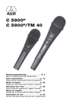
SPC 4
BEDIENUNGSANLEITUNG . . . . . . . . . . . . S. 2
Bitte vor Inbetriebnahme des Gerätes lesen!
USER INSTRUCTIONS
. . . . . . . . . . . . . . . .
p. 1 0
Please read the manual before using the equipment!
MODE D’EMPLOI
. . . . . . . . . . . . . . . . . . . . . .
p. 1 8
Veuillez lire cette notice avant d’utiliser le système!
ISTRUZIONI PER L’USO
. . . . . . . . . . . . . .
p. 2 6
Prima di utilizzare l’apparecchio, leggere il manuale!
MODO DE EMPLEO
. . . . . . . . . . . . . . . . . . . .
p. 3 4
¡Sirvase leer el manual antes de utilizar el equipo!
INSTRUÇÕES DE USO
. . . . . . . . . . . . . . . .
S. 4 2
Favor leia este manual antes de usar o equipamento!
Table of Contents
FCC Statement ......................................................................................................10
1 Safety and Environment ....................................................................................11
1.1 Safety..........................................................................................................11
1.2 Environment................................................................................................11
2 Description .........................................................................................................12
2.1 Introduction.................................................................................................12
2.2 Packing List ................................................................................................12
2.3 Optional Accessories..................................................................................12
2.4 SPC 4..........................................................................................................12
2.4.1 Front Panel ........................................................................................12
2.4.2 Rear Panel .........................................................................................12
3 Getting Started ...................................................................................................13
3.1 Important Notes..........................................................................................13
3.2. Rack Mounting a Single Antenna Combiner...............................................13
3.3 Rack Mounting Two Antenna Combiners Side by Side..............................13
3.4 Setting Up Antennas...................................................................................13
3.4.1 Placement..........................................................................................13
3.4.2 Mounting Antennas on Floor Stands .................................................14
3.4.3 Wall/Ceiling Mounting........................................................................14
3.5 Wiring..........................................................................................................14
3.6 Powering.....................................................................................................15
3.6.1 Using an AC Adapter .........................................................................15
3.6.2 Using the PSU 4000 ..........................................................................15
4 Operating Notes .................................................................................................16
4.1 Powering Up and Down..............................................................................16
4.1.1 Systems with Distributed Power Supplies.........................................16
4.1.2 Systems with PS 4000 Central Power Supplies ................................16
4.2 Status LED..................................................................................................16
5 Cleaning ..............................................................................................................17
6 Specifications.....................................................................................................17
FCC Statement
This equipment has been tested and found to comply with the limits for a Class B
digital device, pursuant to Part 74 of the FCC Rules. These limits are designed to
provide reasonable protection against harmful interference in a residential installation. This equipment generates, uses, and can radiate radio frequency energy and,
if not installed and used in accordance with the instructions, may cause harmful interference to radio communications. However, there is no guarantee that interference will not occur in a particular installation. If this equipment does cause harmful
interference to radio or television reception, which can be determined by turning
the equipment off and on, the user is encouraged to try to correct the interference
by one or more of the following measures:
• Reorient or relocate the receiving antenna.
• Increase the separation between the equipment and the receiver.
• Connect the equipment into an outlet on a circuit different from that to which the
receiver is connected.
• Consult the dealer or an experienced radio/TV technician for help.
Shielded cables and I/O cords must be used for this equipment to comply with the
relevant FCC regulations.
Changes or modifications not expressly approved in writing by AKG Acoustics may
void the user’s authority to operate this equipment.
10
AKG SPC 4
1 Safety and Environment
!
1. Do not spill any liquids on the equipment and do not drop any objects through the
ventilation slots in the equipment.
2. The equipment may be used in dry rooms only.
3. The equipment may be opened, serviced, and repaired by authorized personnel
only. The equipment contains no user-serviceable parts.
4. Before connecting the equipment to power, check that the primary voltage stated
on your power supply is identical to the AC mains voltage available where you will
use the equipment.
5. Operate the equipment with a DC power supply with an output voltage of 12
VDC/1.4 A or the PSU 4000 central power supply from AKG. Using a power supply with a different output voltage may cause serious damage to the unit.
6. If any solid object or liquid penetrates into the equipment, shut down the sound
system immediately. Disconnect the equipment from the power outlet immediately and have the equipment checked by AKG service personnel.
7. If you will not use the equipment for a long period of time, disconnect the equipment from the power outlet. Please note that the equipment will not be fully isolated from power when you set the power switch to OFF.
8. Do not place the equipment near heat sources such as radiators, heating ducts,
or amplifiers, etc. and do not expose it to direct sunlight, excessive dust, moisture, rain, mechanical vibrations, or shock.
9. To avoid damage due to overheating, make sure never to cover or block the ventilation louvers on the equipment front panel.
10. To avoid hum or interference, route all cables away from power lines of any type.
If you use cable ducts, be sure to use separate ducts for the audio lines.
11. Clean the equipment with a moistened (not wet) cloth only. Be sure to disconnect
the AC adapter from the power outlet before cleaning the equipment! Never use
caustic or scouring cleaners or cleaning agents containing alcohol or solvents
since these may damage the enamel and plastic parts.
12. Use the equipment for the applications described in this manual only. AKG cannot accept any liability for damages resulting from improper handling or misuse.
1.1 Safety
1. The AC adapter will draw a small amount of current even when the equipment is
switched off. To save energy, disconnect the AC adapter from the power outlet if
you will leave the equipment unused for a long period of time.
2. When scrapping the equipment, separate the case, circuit boards, and cables,
and dispose of all components in accordance with local waste disposal rules.
3. The packaging of the equipment is recyclabe. Dispose of the packaging in an appropriate container provided by the local waste collection/recycling entity and
observe all local legislation relating to waste disposal and recycling.
1.2 Environment
AKG SPC 4
11
2 Description
2.1 Introduction
Thank you for purchasing an AKG product. This Manual contains important instructions for setting up and operating your equipment. Please take a few minutes to read
the instructions below carefully before operating the equipment. Please keep the
Manual for future reference. Have fun and impress your audience!
2.2 Packing List
1 SPC 4 antenna combiner
1 19" rack mounting kit
2.3 Optional Accessories
2.4 SPC 4
•
Check that the packaging contains all of the items listed above. Should any of
these items be missing, please contact your AKG dealer.
•
For optional accessories, refer to the current AKG catalog or folder, or visit
www.akg.com. Your dealer will be glad to help.
The SPC 4 is an antenna combiner designed for the IVM 4 in-ear monitor system.
The antenna combiner allows you to combine the output signals of up to four SST 4
stereo transmitters into a single antenna signal. The SPC 4 will only operate with the
SRA 2 W passive directional antenna or RA 4000 W passive omnidirectional antenna
from AKG.
The SPC 4 can be powered either from an AC adapter with an output voltage of
12 VDC/≥1.4 A (not included) or the optional PSU 4000 central power supply.
2.4.1 Front Panel
Fig. 1: SPC 4 front panel.
1
Refer to fig. 1.
1
2
3
2
3
ON/OFF: Pushbutton for switching power to the unit on and off.
Status LED: This tricolor LED indicates the following operating conditions:
Green: Power to the unit is on, the operating temperature is within the safe range.
Orange: Critical operating temperature, the unit may overheat.
Red: The unit has overheated or is connected to an antenna not approved by
AKG. Switch power to the unit off to avoid damage to the unit.
Ventilation grill: The unit incorporates a ventilator for cooling the electronic circuitry.
2.4.2 Rear Panel
Fig. 2: Inputs and outputs
on the SPC 4 rear panel.
Refer to fig. 2.
4
4
5
6
7
12
5
5
5
5
7
6
ANTENNA OUT: BNC output connector for an SRA 2 W or RA 4000 W transmitting antenna. You may also connect this output to a transmitter input on another
SPC 4.
INPUT 1-4: BNC inputs for connecting one to four SST 4 stereo transmitters.
DC ONLY 12 V/1.4 A SPC 4: DC input for an AC adapter with a 12 VDC/≥1.4 A
output (not included) for powering the SPC 4.
DC ONLY 12 V/2 A SST: DC input for connecting the optional PSU 4000 central
power supply for powering the SST 4 transmitters connected to the SPC 4.
AKG SPC 4
3 Getting Started
3.1 Important Notes
1. Make all antenna cable connections before connecting the unit to power.
2. Do not connect to the SPC 4 to any antenna other than the SRA 2 W or
RA 4000 W from AKG. Using other antenna types may cause malfunctioning
of the SPC 4.
3. Position the unit such that the front panel ventilation grill cannot be covered. Obstructing the air intake may cause the unit to overheat.
!
1. Unscrew the four rubber feet (1) from the antenna combiner bottom panel.
2. Unscrew the two fixing screws (2) from each side panel.
3. Use the fixing screws (2) to screw the short bracket (3) to one side panel and the
long bracket (4) to the other side panel. The brackets are contained in the supplied rack mounting kit.
4. Install the antenna combiner in your rack.
3.2. Rack Mounting a
Single Antenna Combiner
Refer to fig. 6.
1. Unscrew the four rubber feet (1) from each antenna combiner's bottom panel and
remove the screws (5) from the rubber feet (1).
2. Unscrew the two fixing screws (2) from the right-hand side panel of one antenna
combiner and from the left-hand side panel of the other antenna combiner.
3. Remove the plastic covers (3) from the side panels with the fixing screws (2) still
on.
4. Insert one connecting strip (4) into each free slot in the side panel of the first antenna combiner, making sure to align the hole in each connecting strip (4) with the
appropriate threaded hole in the antenna combiner bottom panel.
5. Fix the two connecting strips (4) on the first antenna combiner using two of the
screws (5) you removed from the rubber feet.
6. To join the two antenna combiners, slide the connecting strips (4) on the first antenna combiner through the free slots in the side panel of the second antenna
combiner. Make sure to align the hole in each connecting strip (4) with the appropriate threaded hole in the bottom panel of the second antenna combiner.
7. Fix the two connecting strips (4) on the second antenna combiner using two of
the screws (5) you removed from the rubber feet.
8. Screw a short bracket (6) to the outer side panel of each antenna combiner using
for each bracket two of the screws (2) you removed from the antenna combiner
side panels.
9. Install the antenna combiners in your rack.
3.2. Rack Mounting a
Single Antenna Combiner
Refer to fig. 6.
The following hints on placing the antenna apply to any multichannel system, no matter how many channels it may use.
3.4 Setting Up Antennas
Reflections off metal parts, walls, ceilings, etc. or the shadow effects of musicians and
other people may weaken or cancel the direct transmitter signal. For best results,
place the antenna as follows:
3.4.1 Placement
1. Place the antenna near the performance area (stage).
2. Place the antenna at least 5 ft. (1.5 m) away from any big metal objects, walls,
scaffolding, ceilings, etc.
3. Do not place the antenna in a wall recess.
4. Place the antenna at least 5 ft. (1.5 m) away from any equipment that may emit
RF radiation such as lighting racks, fluorescent lamps, digital effects units, or
PCs.
AKG SPC 4
13
3 Getting Started
3.4.2 Mounting Antennas
on Floor Stands
•
When mounting the antenna on a floor stand, be sure to proceed as follows:
1. Use the supplied SA 63 or the integrated stand
adapter to mount the antenna on the boom of a boom
stand.
2. Pull the boom out all the way to one side to make
sure the antenna will be at least 28 inches (70 cm)
away from the stand.
3. Extend the stand high enough to place the boom at
least 6 ft. (1.8 m) above the floor.
4. Wind the antenna cable around the boom. Do not
allow the cable to sag below the boom because this
may degrade the reception quality.
≥ 70cm
˛
˛
˛
≥ 150cm
˛
Fig. 3: Antenna mounted
on a floor stand.
1. Mount the antenna at least 10 cm (4 in.) in front of and
at a minimum lateral distance of 50 cm (20 in.) from
any walls or other plane surfaces, metal grids, or
metal scaffolding.
˛
3.4.3 Wall/Ceiling
Mounting
˛
≥ 10cm
˛
˛
≥ 50cm
˛
˛
≥ 50cm
Fig. 4: Minimum distances
from plane surfaces.
˛
2. Make sure the antenna will sit at least 15 cm (6 in.)
above the floor or 50 cm (20 in.) from the ceiling (or
15 cm (6 in.) if you route the cable to the antenna from
above).
˛
˛
≥ 50 (15) cm
≥ 15cm
3.5 Wiring
Note:
˛
Fig. 5: Minimum distances
from floor and ceiling.
1. Connect the ANTENNA output on each transmitter to one of the INPUT connectors on the antenna combiner.
Use the shortest possible RG58 antenna cables.
2. If several signals are radiated by a shared antenna, intermodulation of the various
carrier frequencies will cause spurious emissions.
To avoid technical and legal problems (official limits for RF output and spurious
emissions), set the RF OUTPUT level on each transmitter as follows (also refer to
the IVM 4 User Manual):
•
Transmitters
Max. RF OUTPUT per transmitter
2 to 4
20 mW
≥4
10 mW
If you need to use a multichannel system with a higher RF output, please contact
AKG Sales at [email protected].
3. Connect the antenna to the ANTENNA OUT connector on the antenna combiner.
Important!
14
!
•
Please note that these antennas may boost their RF output (ERP) in their
preferred directions. In order to keep RF output within legal limits, make
sure to use antenna cables of the correct length for each type of cable, e.g.,
RG58: 16 ft. (5 m) for an RA 4000 W or 33 ft. (10 m) for an SRA 2 W.
AKG SPC 4
3 Getting Started
•
To power the SPC 4 you can use either a suitable AC adapter or the optional
PSU 4000 central power supply.
3.6 Powering
•
Do not use any AC adapter other than a type delivering an output voltage of
12 VDC and an output current of 1.4 A or higher.
Check that the AC mains voltage stated on your power supply is identical to
the AC mains voltage available where you will use your system. Using the
power supply with a different AC voltage may cause irreparable damage to
the unit.
If you connected neither a suitable standard AC adapter nor a PSU 4000 to
DC ONLY 12 V/2 A SST, you will need to power each transmitter from a separate power supply.
3.6.1 Using an AC Adapter
Important!
•
•
!
1. Plug the DC cable of your AC adapter into the DC ONLY 12 V/1.4 A SPC 4 jack
on the antenna combiner rear panel.
2. Connect the AC adapter to a convenient AC outlet.
1. Connect the DC OUT 1 jack on the PSU 4000 to the DC ONLY 12 V/2 A SST jack
on the antenna combiner rear panel.
2. Connect the DC OUT 2 or DC OUT 3 jack on the PSU 4000 to the DC ONLY
12 V/1.4 A SPC 4 jack on the antenna combiner rear panel.
AKG SPC 4
3.6.2 Using the PSU 4000
Refer to fig. 8 and the
PSU 4000 User Manual.
15
4 Operating Notes
4.1 Powering Up
and Down
Important!
!
•
To prevent damage from overloading the antenna combiner power supply,
always switch power to the various components of your system on and off
in the order described in sections 4.1.1 and 4.1.2.
4.1.1 Systems with Distributed Power Supplies
Powering Up:
1. Press the ON/OFF key on the antenna combiner to switch power to the antenna
combiner ON.
The status LED will be lit green.
2. Switch ON all transmitters connected to the antenna combiner.
Powering Down:
1. Switch OFF all transmitters connected to the antenna combiner.
2. Press the ON/OFF key on the antenna combiner to switch power to the antenna
combiner OFF.
The status LED will extinguish.
4.1.2 Systems with
PSU 4000 Central
Power Supplies
Powering Up:
1. Switch the PSU 4000 central power supply ON.
2. Press the ON/OFF key on the antenna combiner to switch power to the antenna
combiner ON.
The status LED will be lit green.
3. Switch ON all transmitters connected to the antenna combiner.
Powering Down:
1. Switch OFF all transmitters connected to the antenna combiner.
2. Press the ON/OFF key on the antenna splitter to switch power to the antenna
splitter OFF.
The status LED will extinguish.
3. Switch the PSU 4000 central power supply OFF.
4.2 Status LED
Green
The antenna combiner is
ON and connected to an
antenna approved by
AKG. The operating temperature is within the safe
range.
Orange
The operating temperaSwitch power to the anture has reached a critical tenna combiner OFF and
level.
make sure that the ventilation grill is not obstructed.
Red
The antenna combiner
has overheated.
Switch power to the antenna combiner OFF and
make sure that the ventilation grill is not obstructed and the power
supply is connected correctly.
The antenna connected to
the antenna combiner is
not a type approved by
AKG is .
Switch power to the antenna combiner OFF and
connect an SRA 2 W or
RA 4000 W antenna.
Power to the antenna
combiner is OFF.
Switch power to the antenna combiner ON.
Dark
The antenna combiner is Connect the antenna
not connected to a power combiner to your power
supply.
supply.
The DC cable(s) is/are not Connect or replace the
connected or defective.
DC cable(s).
The AC adapter or
PSU 4000 is defective.
16
Contact your nearest AKG
Service Center.
AKG SPC 4
5 Cleaning
1. Disconnect the unit from power.
2. To clean the receiver surfaces, use a soft cloth moistened (not soaked!) with water.
•
Never use any caustic or scouring cleaners or cleaning agents containing alcohol or solvents since these may damage the enamel and plastic parts.
! Important!
6 Specifications
Type:
Carrier range:
System gain:
RF inputs:
RF outputs:
Power requirement:
Power supply (for SST 4s):
Dimensions:
Weight:
4 to 1 antenna combiner
500 MHz to 865 MHz
0 dB
4 BNC sockets, 50 ohms
1 BNC socket, 50 ohms
12 VDC/900 mA
12 VDC/2 A
200 x 190 x 44 mm (7.8 x 7.5 x 1.7 in.)
1,193 g (2.63 lbs)
This product conforms to the standards listed in the Declaration of Conformity. To
order a free copy of the Declaration of Conformity, visit http://www.akg.com or contact [email protected].
AKG SPC 4
17
A
C
B D
Fig. 6
A
B
C
D
Fig. 7
50
AKG SPC 4
SRA 2 W
SST 4
SST 4
SST 4
SST 4
DC ONLY 12 V/1.4 A
SPC 4
DC ONLY 12 V/2 A
PSU 4000
DC OUT 2
DC OUT 1
Fig. 8
AKG SPC 4
51
Mikrofone · Kopfhörer · Drahtlosmikrofone · Drahtloskopfhörer · Kopfsprechgarnituren · Akustische Komponenten
Microphones · Headphones · Wireless Microphones · Wireless Headphones · Headsets · Electroacoustical Components
Microphones · Casques HiFi · Microphones sans fil · Casques sans fil · Micros-casques · Composants acoustiques
Microfoni · Cuffie HiFi · Microfoni senza filo · Cuffie senza filo · Cuffie-microfono · Componenti acustici
Micrófonos · Auriculares · Micrófonos inalámbricos · Auriculares inalámbricos · Auriculares con micrófono · Componentes acústicos
Microfones · Fones de ouvido · Microfones s/fios · Fones de ouvido s/fios · Microfones de cabeça · Componentes acústicos
AKG Acoustics GmbH
Lemböckgasse 21–25, A-1230 Vienna/AUSTRIA, phone: (+43-1) 86654-0*
e-mail: [email protected]
AKG Acoustics, U.S.
8500 Balboa Boulevard, Northridge, CA 91329, U.S.A, phone: (+1 818) 920-3212
e-mail: [email protected]
For other products and distributors worldwide visit www.akg.com
Technische Änderungen vorbehalten. Specifications subject to change without notice. Ces caractéristiques sont susceptibles de modifi-cations. Ci
riserviamo il diritto di effettuare modifiche tecniche. Nos reservamos el derecho de introducir modificaciones técnicas. Especificações sujeitas a
mudanças sem aviso prévio.
Printed in Austria.
03/07/9100 U 1230