1
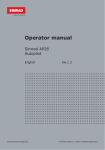
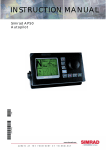
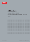
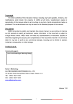
Addendum
Simrad NSE8 and NSE12
For NSE 2.0 Features
English
www.simrad-yachting.com
A brand by Navico - Leader in Marine Electronics
Contents
1
Installing autopilot in the NSE system ............................................3
Wiring the autopilot system ................................................................ 3
Verifying the autopilot connection........................................................ 3
Commissioning the autopilot ............................................................... 3
Dockside setup ................................................................................. 4
Seatrials .......................................................................................... 6
Manually adjusting steering parameters ............................................. 10
2
Using the autopilot ....................................................................... 13
Autopilot indication on NSE panels ..................................................... 13
Safe operation with the autopilot ....................................................... 13
The autopilot panel .......................................................................... 14
Autopilot mode overview .................................................................. 15
Selecting autopilot modes ................................................................ 15
Using the autopilot in Standby mode .................................................. 16
Follow-up steering (FU) .................................................................... 16
AUTO mode (auto compass) .............................................................. 16
NoDrift mode .................................................................................. 20
Navigating with the NSE ................................................................... 20
Sailing with the autopilot .................................................................. 22
Wind steering and navigation ............................................................ 24
Control of steering performance ........................................................ 24
Using the NSE in an AP24/AP28 system .............................................. 25
3
Using BEP CZone ........................................................................... 26
The BEP CZone panel ....................................................................... 27
Operating the modes function ........................................................... 28
System overview options.................................................................. 28
The BEP CZone dashboard ................................................................ 29
Editing the new dashboard ............................................................... 29
4
New Navionics features ...............................................................30
Navionics Fish-n-Chips ..................................................................... 30
Setting extension lines on chart ........................................................ 30
5
New radar features ....................................................................... 31
Target tracking on radar and chart panels .......................................... 31
True Motion .................................................................................... 31
Using Fast scan mode ...................................................................... 31
Table of contents | 1
6
Using StructureScan ..................................................................... 32
StructureScan panel ........................................................................ 32
The StructureScan image ................................................................. 32
Pausing StructureScan .................................................................... 32
Setting up the StructureScan display ................................................. 33
Using Structure palettes................................................................... 34
Using the cursor on the StructureScan panel ...................................... 34
Optimizing the StructureScan image .................................................. 35
Recording the StructureScan data ..................................................... 36
2 | Table of contents
1 Installing autopilot in the NSE system
If an AC12 or AC42 autopilot computer is connected to the NSE system, autopilot
functionality will be included in the NSE.
The NSE can be connected to a full autopilot system including an AP24 or AP28 control
head, or the NSE can be used as the only control head in the autopilot system.
Wiring the autopilot system
The AC12/AC42 is connected to the NSE system using the SimNet network.
For more information about how to install and wire the units, refer to the separate AC12/
AC42 Installation manual (part no 20222568) and to the NSE Installation manual (part no
988-0175-03).
x2
x2
MENU
WIN
Verifying the autopilot
connection
MENU
WIN
When an AC12 or AC42 is connected to the
NSE system, the NSE will automatically detect
the autopilot and an Autopilot menu item will
be included in the Settings menu.
If no Autopilot item is available in the menu,
establish the connection by running the auto
select process.
The auto select process may also be used if
the list of data sources needs to be updated
when a unit has been physically replaced.
If the AC12/42 later is disconnected the
Autopilot menu item will remain available, but
only a few of the menu items will be available.
Commissioning the autopilot
Before you perform any commissioning of the autopilot, the hardware installation
and electrical connections must be completed as described above and in the separate
AC12/24 Installation manual.
When the autopilot installation is confirmed, the commissioning procedures must be
performed. Failure in setting up the autopilot correctly may prohibit the autopilot from
functioning properly.
The setup of the autopilot computers (AC12/42) can be done from the NSE unit or from
the AP24 or AP28 control head if such is included in the system. The following sections
describe how you configure the autopilot from the NSE unit. If you select to setup the
system from an AP24 or AP28 control head, refer to the AP24 Operator manual (part no
20222535) or the AP28 Operator manual (part no 20222527).
If you connect the NSE to an already commissioned autopilot system, you only have to
do an automatic source selection as described above before the autopilot is ready to be
used.
Autopilot installation | 3
Dockside setup
You initiate the required dockside procedures from the commissioning dialog. Completed
procedures are labelled with a tick.
x2
MENU
WIN
When the autopilot computer is delivered from factory AND ANY TIME AFTER AN
AUTOPILOT RESET HAS BEEN PERFORMED, you will have to run a complete setup again.
All steps in all commissioning procedures are clearly described on-screen, and you will
be guided step by step through the process.
1
Press the STBY/AUTO key to ensure that the autopilot is in standby mode
2
Activate the autopilot commissioning dialog as shown above
3
Select boat type
-
4
The boat type setting is used by the system to select appropriate preset steering
parameters. It will also affect available autopilot features.
Perform the rudder calibration
a Rudder feedback calibration
-
Used if you have a rudder feedback unit installed. This calibration is used to ensure
that the physical rudder movement corresponds to the rudder angle displayed on
the NSE unit.
b VRF (Virtual Rudder Feedback) calibration
-
The Virtual Feedback option enables your autopilot to steer without a conventional
rudder feedback unit. This function is designed for vessels up to 40 ft. powered by
outboard or stern drives only.
-
The Virtual Feedback option will only be available when there is no feedback unit
connected at first time turn on or at turn on after an autopilot reset.
Installing a feedback unit will enhance the performance of the autopilot and provide an
accurate rudder angle indicator on the autopilot display. Unless impractical or impossible,
a rudder feedback unit should be installed.
5
Set the drive voltage
-
6
Refer to the drive unit table in the AC12/AC42 Installation manual or to your drive
unit documentation for information.
Run the rudder test as described in the on-screen instructions
If the boat uses power assisted steering, it is important that the engine or electric motor
used to enable the power assist steering is turned on prior to this test.
4 | Autopilot installation
Stand CLEAR of the wheel and do not attempt to take manual control of the
wheel during this test!
-
When this test is started the autopilot computer will issue a series of PORT and
STBD rudder commands and automatically verify correct rudder direction. It
detects minimum power to drive the rudder and reduces the rudder speed if it
exceeds the maximum preferred speed (8°/sec.) for autopilot operation. The
system will also detect whether the drive unit is a reversible motor or if a solenoid
valve is operated.
Rudder drive setup
The rudder drive setup controls how the autopilot computer
controls the steering system.
Drive voltage
Voltage specified for your drive unit.
The Drive unit voltage setting does not apply when the system
operates solenoids on a continuous running pump/steering gear.
Hence, the output voltage to the solenoids will be the same as the
input voltage.
Refer to the drive unit table in the AC12/AC42 Installation manual or to your drive unit
documentation for information.
Selection of improper voltage level for your drive unit may damage both the
drive unit and the AC12/42 even if the protection circuits are activated.
Drive engage
Clutch
Auto
This is the default setting and it allows you to steer the boat
with the helm or wheel when in STBY mode (FU and NFU
modes) as well as in all auto steering modes
This option is typically used to switch between two rudder
speeds on a continuous running pump, used when different
rudder speeds are required for automatic and Follow-up/NonFollow-up steering
Motor output
Shows the amount of power needed to achieve the correct rudder speed. The reading is
obtained from the Rudder test.
The automatically set value may be increased or decreased.
Rudder deadband
This parameter is used to prevent the rudder from hunting. The reading is obtained from
the Rudder test which optimizes the deadband to the speed of the boat and the pressure
on the rudder.
If the auto-setting does not perform properly due to high inertia from the wheel or a
loose steering gear, it can be adjusted manually. Find the lowest possible value that
will prevent the rudder from continuous hunting. A wide deadband will cause inaccurate
steering.
The rudder deadband setting is not available when the autopilot is configured for Virtual
Rudder Feedback.
Autopilot installation | 5
Seatrials
A seatrial can only be performed if the dockside settings are completed and confirmed.
The seatrial must always be performed in open waters at a safe distance from other
traffic.
You can switch the autopilot to standby mode and take manual control of the boat at any
time during the seatrial by pressing the STBY/AUTO key.
The following seatrial calibration should be done:
-
Compass calibration; used to automatically compensate for on-board magnetic
interference
-
Compass offset adjustment, used to compensate for a fixed offset in the final
heading readout
-
Wind calibration to compensate for a fixed mechanical offset of the Wind vane *
-
Boat speed calibration *
-
Transition HI/LO speed setting (the speed at which you want to change the set of
steering parameters)
-
Automatic tuning of the steering parameters
-
Setting the seastate filer
-
Saiboat setup
* Described in the separate NSE Installation manual.
Compass calibration
Before the compass calibration is started, make sure that there is enough open water
around the vessel to make a full turn.
The calibration should be done in calm sea conditions and with minimal wind to obtain
good results. Follow the on-screen instruction, and use about 60-90 seconds to make a
full circle.
x2
MENU
WIN
6 | Autopilot installation
During the calibration, the compass will measure the magnitude and direction of the local
magnetic field. Refer graphic on next page.
-
If the local magnetic field is stronger than the earth’s magnetic field (the local field
is reading more than 100%), the compass calibration will fail
-
If the local field is reading more than 30%, you should look for any interfering
magnetic objects and remove them, or you should move the compass to a different
location. The (local) field angle will guide you to the local interfering magnetic
object.
Calibration must be made on the compass that is active for the autopilot. If another
model compass from Simrad or another manufacturer is installed, refer to the instruction
for that compass regarding calibration.
LUBBER LINE
20%
Magnitude of local field
in % of earth’s magnetic
field.
10
Direction of local field
with respect to lubber
line. It can also be on the
reciprocal.
In certain areas and at high latitudes the local magnetic interference becomes more
significant and heading errors exceeding ±3° may have to be accepted.
Compass mounting offset
After compass calibration, the difference between the compass lubber line and the boat’s
center line should be compensated for.
1
Find the bearing from the boat position to a visible object. Use a chart or a chart
plotter
2
Steer the boat so that the center line of the boat is aligned with the bearing line
pointing towards the object
3
Change the offset parameter so that the bearing to the object and the compass
readout becomes equal. Refer graphic above
Make sure that both the compass heading and the bearing to the object have the same
unit (°M or °T).
Autopilot installation | 7
Setting the transition HI/LO speed
This is the speed at which the system automatically
changes from LO to HI steering parameters.
On power boats it is recommended that you set a value
that represents the speed where the hull begins to plane
or the speed where you change from slow to cruising
speed.
On sailboats the transition speed should be set to 3-4
knots to give the best response in a tack.
res
LO
res
HI
po
ns e
po
ns e
Transition to LO parameters
with increasing speed: 10kn
Transition speed set to 9kn
Transition to HI parameters
with decreasing speed: 8kn
Active response parameter set is shown in the autopilot popup, and the following
abbreviations are used:
HI-A
High response parameters set automatically
LO-A
Low response parameters set automatically
HI-M
High response parameters set manually
LO-M
Low response parameter set manually
Autotuning
The autotune feature will run the boat through several tests and then automatically set
the most important steering parameters.
Autotune is not required for the autopilot to function as it is preset with steering
parameters that should steer most boats in the 30-50 foot range.
You can manually set all parameters that are set during autotuning. Refer next page.
Seastate filter
The Seastate filter is used to reduce rudder activity and autopilot
sensitivity in rough weather.
8 | Autopilot installation
OFF
Seastate filter is disabled. This is default
AUTO
Reduces rudder activity and autopilot
sensitivity in rough weather by an adaptive
process. The AUTO setting is recommended if
you want to use the seastate filter
MANUAL
Linked to the steering response control
settings described previously. It may be used
to manually find the optimum combination of
course keeping and low rudder activity in rough
but steady sea conditions
Setting sailing parameters
Sailing parameter settings are only available if the
boat type is set to Sail.
Tack time
When performing a tack in WIND mode, the rate of
turn (tack time) can be adjusted. This will give singlehanded sailors time to handle the boat and the sails
during a tack.
A turn performed without shifting wind side, will also
be made at a controlled turn rate.
Range
Change per step
Default
Units
2 - 50
1
12
seconds
Tack angle
This value is used to preset the course change used when tacking in AUTO mode. By
pressing the left/right arrow keys the course will change as much as this value.
Range
Change per step
Default
Units
50 - 150
1
100
°
Wind function
With wind function set to Auto, the autopilot will automatically select between apparent
and true wind steering. Auto is default and recommended for cruising.
When the boat is running, it will also be surfing on the waves. This may lead to
significant changes in boat speed, and thereby also changes in apparent wind angle. True
wind steering is therefore used when running, while steering to apparent wind is used
when beating or reaching.
Apparent wind steering is preferred when you want to achieve maximum boat speed. The
autopilot tries to maintain a constant apparent wind angle to get maximum thrust from a
given trim of the sails.
When sailing in closed waters, the apparent wind angle may change temporarily due to
wind gusts. It may then be preferred to sail to the true wind.
VMG optimizing
You can optimize the VMG to wind. When selected the function will be active for 5–10
minutes after a new wind angle has been set and only when beating.
Layline steering
Layline steering is useful when navigating. Cross Track Error (XTE) from the navigator
will keep the boat on the track line. If the XTE from the navigator exceeds 0.15 nm, the
autopilot will calculate the layline and track towards the waypoint.
Autopilot installation | 9
Manually adjusting steering parameters
The autotune function in the autopilot is so refined that the majority of boats will need
no further adjustments of the steering parameters. On some boats, however, or at
particular sea conditions a fine tuning of the steering parameters may improve the
performance of the autopilot.
x2
MENU
WIN
Transition speed
Refer previous description.
Rudder
This parameter determines the ratio between commanded rudder and the heading error.
The higher rudder value the more rudder is applied.
If the value is too small it will take a long time to compensate for a heading error, and
the autopilot will fail to keep a steady course.
If the value is set too high the overshoot will increase and the steering will be unstable.
Counter rudder
Counter rudder is the amount of rudder used to try to prevent the boat from yawing
around the set course. Higher counter rudder settings result in more rudder being
applied.
The best way of checking the value of the Counter rudder setting is when making turns.
The figures illustrate the effects of various Counter Rudder settings;
A: Counter rudder too low; overshoot response
B: Counter rudder too high; sluggish and creeping response
C: Correct setting or counter rudder; ideal response
A
10 | Autopilot installation
B
C
Auto trim
This parameter defines how fast the autopilot shall correspond after having registered a
heading error.
The standard value is 40 seconds which should work well on most boats. Rule of thumb:
Set to same value (seconds) as the boat’s length in feet. On boats operating on VRF the
value should be set to 20 seconds.
Rate limit
Sets the maximum allowed rate of turn.
The value should be kept at 6.0°/second unless there is a need for more rapid response
in turns.
Minimum rudder
This parameter filters small rudder commands to prevent high rudder activity.
Some boats may have a tendency to not respond to small rudder commands around
the “course keeping” position because of a small rudder, a rudder deadband, whirls/
disturbance of the water-stream passing the rudder or it is a single nozzle water jet boat.
By increasing the Minimum rudder parameter you may improve the course keeping
performance on some boats. This will however increase the rudder activity.
Minimum wind angle to port and starboard
These parameters should be set identical to the minimum apparent wind angle that will
keep the sails well shaped and give an acceptable thrust. The parameters will vary from
boat to boat.
The settings are used for the tack-prevent function. They also applies when the autopilot
is operating in WindNAV mode. Refer to the Operating the autopilot section.
You can select different minimum wind angles for port and starboard. The difference
between port and starboard will be taken into account when calculating the Distance To
Turn (DTT).
Navigation change limit
This parameter defines the maximum course change where the autopilot is allowed to
automatically change the course when the NSE follows a route (NAV steering).
If the required course change to next waypoint in a route is more than the set limit, you
are prompted to verify that the upcoming course change is acceptable.
Autopilot installation | 11
Blank page
12 | Autopilot installation
2 Using the autopilot
If an AC12 or AC42 autopilot computer is connected to the NSE system, autopilot
functionality will be included in the NSE.
The Autopilot feature is designed to maintain an accurate course in various sea
conditions with minimal helm movements. As the autopilot steers so accurately, it will
save fuel and get you to your destination faster, especially when navigating to a waypoint
or following a route.
Autopilot indication on NSE panels
The autopilot pop up
You can only operate the autopilot when the pop up is
active.
You use different key presses to activate the pop-up;
-
a short press on the STBY/AUTO key activates STBY
mode and the pop-up
-
a long press on the STBY/AUTO key activates the
pop-up in current mode.
You remove the pop-up from a page by pressing the X key.
The autopilot popup shows active mode, heading, rudder and various steering
information depending on active autopilot mode.
x2
MENU
WIN
The pop-up has a fixed position on the page, and it can be shown on all pages except
when an Autopilot panel is active.
Autopilot mode indication in top of the page
Autopilot information is by default shown in top of the pages when
the autopilot pop-up is not displayed.
You can select to turn this information off.
Compass symbol on the chart panel
You can select to show a compass symbol around you boat on the
chart panel. The compass symbol will be removed when the cursor
is active on the panel.
Safe operation with the autopilot
An autopilot is a useful navigational aid, but DOES NOT under any circumstances replace a human navigator.
Switching from automatic mode to manual operation
You can switch the autopilot to STBY mode from any automatic operation by a short
press on the STBY/AUTO key.
Autopilot operation | 13
Locking an NSE unit
x2
MENU
WIN
If several NSE units or AP24/AP28 control units are included
in the system, a non-active NSE unit can be locked to prevent
unauthorised operation of the autopilot.
When the unit is locked this is indicated with a lock symbol and
with text in the pop up.
When the lock function is in use, no automatic modes can be selected from the NSE unit.
The lock function is not available on an active NSE unit!
If the NSE unit is part of an AP24/AP28 system, the unit can be locked from the AP24/
AP28 control unit. Refer to Locking remote stations at the end of this chapter.
The autopilot panel
The autopilot panel can be used to display information when you are navigating. The
panel can be added to the NAV page groups or to any other pages groups as described in
the NSE Operator manual.
Data fields
The autopilot panel shows destination name, heading and rudder information. The
following abbreviations are used:
14 | Autopilot operation
CTS
Course to steer
DTD
Distance to destination
SOG
Speed over ground
COG
Course over ground
DTW:
Distance to next waypoint
XTE:
Cross track error
Autopilot mode overview
The autopilot has several steering modes. Number of modes and features within the
mode depend on boat type and available input as shown below.
MODE
FEATURE
BOAT TYPE
MOTOR
DESCRIPTION
SAIL
REQUIRED INPUT
Passive mode used when
steering the boat at the helm
STAND BY
x
x
Controls the rudder
movement by using the
arrow keys
Rudder feedback
FOLLOW-UP
(FU)
x
x
Sets rudder angle by using
the arrow keys
Rudder feedback
AUTO
(COMPASS)
x
x
Keeps the boat on set
heading
x
x
Cancels the turn and
continues on the heading
read from the compass
Power steering
(NFU)
Heading capture
Turn (Pattern)
Moves the boat automatically Heading, speed
in pre-defined turn steering
patterns (Motorboats only)
x
x
Changes commanded
heading with a pre-defined
value
x
x
Keeps the boat on a straight
bearing line
x
x
Resumes NoDrift mode after
a heading change
x
x
Steers the boat to a specific
Heading, speed,
waypoint location, or through position, waypoint/
a route of waypoints
route information
x
Steers the boat to maintain
the set wind angle
x
Mirrors the set wind angle to
the opposite side of the bow
x
Heading, speed,
Steers the boat to a specific
wind angle,
waypoint location, or through
waypoint/route
a route of waypoints
information
Turn (Tacking)
NO DRIFT
Dodging
NAVIGATION
WIND
Tacking
WIND NAV
Heading, speed,
position
Heading, speed,
wind angle
Controlling steering performance in automatic modes
The autopilot should be configured during installation and setup. Some parameters may
adjusted during operation to increase the steering performance. Refer description at the
end of this section.
Selecting autopilot modes
You select an automatic mode or a feature from the Autopilot Mode selection menu.
MENU
WIN
Autopilot operation | 15
Using the autopilot in Standby mode
The autopilot must be in STBY mode when you steer the boat at
the helm.
You can switch the autopilot to STBY mode from any operation by
a short press on the STBY/AUTO key.
Power steering (NFU)
If you press the arrow keys when the autopilot is in STBY mode,
the system will switch to NFU (Non-Follow-Up). You can then use
the arrow keys to control the rudder, and the rudder will move
as long as the key is pressed.
You return to STBY mode by a short press on the STBY/AUTO
key.
Follow-up steering (FU)
You can select Follow-up steering from the Autopilot menu.
When FU is active you can use the rotary knob to set rudder
angle. The rudder will move to the commanded angle and then
stop.
While in Follow-up mode you cannot take manual control
of the wheel.
You return to STBY mode by a short press on the STBY/AUTO key.
AUTO mode (auto compass)
When the AUTO key is pressed, the autopilot selects the current
boat heading as the set course and maintains the rudder angle.
This gives a bumpless transfer at the mode change.
The autopilot will keep the boat on the set course until a new
mode is selected or a new course is set with the course knob or
the PORT or STBD keys.
Once the course is changed to a new set course, the boat will
automatically turn to the new heading and maintain the new course.
Heading capture
When in AUTO or NoDrift mode the heading capture feature allows you to automatically
cancel the turn you are in by an instant press on the rotary knob. The autopilot will
cancel the turn to continue on the heading read from the compass the very moment you
pressed the rotary knob. This is a useful feature if you are not sure of the exact turn you
have to make to hit e.g. an inlet or a dock.
Turn pattern steering (power boats)
The autopilot includes a number of automatic turn steering features for power boats
when the pilot is in AUTO mode.
The turn steering option will not available if the boat type is set to sailboat.
16 | Autopilot operation
Initiating a turn
The illustration below shows how you start the spiral turn steering from the Autopilot
menu.
You select the turn direction and start the turn by using the left or right arrow keys or
the rotary knob.
MENU
WIN
Stopping the turn
You can at any time during a turn press the AUTO/STBD key to return to standby mode
and manual steering.
Turn variables
All turn steering options, except the C-turn, have settings that you may adjust before
you start a turn and at any time when the boat is in a turn. Refer to the example above.
U turn
U-Turn changes the current set course to be
180° in the opposite direction.
The turn rate is identical to default rate of
turn (ROT) setting. This cannot be changed
during the turn.
C-turn
C-turn makes the boat turn in a circle.
You can adjust the turn rate (ROT) before
the turn is initiated and during the turn.
Increasing the turn rate makes the boat to a
smaller circle.
Turn parameter
Rate of turn (ROT)
Range
Change
per step
Default
Units
10 - 600
5
90
°/min
Autopilot operation | 17
Spiral-turn
Spiral-turn makes the boat turn in a spiral with a decreasing or increasing radius. This
feature may be used for circling fish or when searching an object on the seabed.
If the Change radius is set to zero, the boat will turn in a circle. Negative values indicate
decreasing radius while positive values indicate increasing radius.
Turn parameter
Initial radius
Change of radius per turn
Range
Change per step
Default
33 ft - 3281 ft
10
656 ft
10 m - 1000 m
10
200 m
-164 ft - +164 ft
5
66 ft
-50 m - +50 m
2
20 m
Zigzag-turns
While sailing in a zigzag pattern,
you set the initial course change
before the turn is started.
C
During the turn you can alter
the course change and the leg
distance.
A
The main course can be changed
by turning the rotary knob.
B
A = Initial course change
B = Course change
C = Leg distance
Turn parameter
Course change
Leg distance
Range
Change per step
Default
4° - 140°
4
28°
82 ft - 9843 ft
50
1641 ft
25 m - 3000 m
25
500 m
Square-turn
The square-turn feature makes
the boat automatically turn 90°
after having travelled a defined leg
distance.
You can at any time during the
turn change the distance of the
leg until the boat makes a new
90° turn. You can also at any time
change the main course by turning
the rotary knob.
Turn parameter
Leg distance
18 | Autopilot operation
Range
Change per step
Default
82 ft - 9843 ft
50
1641 ft
25 m - 3000 m
25
500 m
Lazy S-turn
In the lazy-s turn the boat will yaw
around the main course.
You set the selected course change
before the turn is started.
During the turn you can alter the
course change and the turn radius.
The main course can be changed
by turning the rotary knob.
Turn parameter
Course change
Radius
Range
Change per step
Default
4° - 160°
4
28°
16 ft - 1641 ft
5
656 ft
5 m – 500 m
10
200 m
Depth Contour Tracking, DCT
TM
If the system has input from an echo sounder, the autopilot can be set to follow a depth
contour.
Do not use this feature unless the seabed is suitable. Do not use it in rocky
waters where the depth is varying significantly over a small area.
Slope
Narrow
channel
Ridge
Use the following process to initiate DCT steering;
1
Ensure that you have depth reading on the NSE unit or on a separate depth
instrument
2
Steer the boat to the depth you want to track, and in the direction of the depth
contour (main course)
3
Activate AUTO mode, select DCT steering and monitor the depth reading
4
Use the Starboard or Port buttons to initiate the DCT steering depending on if the
bottom slopes to starboard or to port
The following parameters are available for DCT steering:
Turn parameter
Depth gain
Contour Cross Angle
Range
Change per step
Default
5 - 95
5
5
0° - 50°
1
0
Autopilot operation | 19
Depth gain
This parameter determines the ratio between commanded rudder and the deviation from
the selected depth contour. The higher depth gain value the more rudder is applied.
If the value is too small it will take a long time to compensate for drifting off the set
depth contour, and the autopilot will fail to keep the boat on the selected depth.
If the value is set too high the overshoot will increase and the steering will be unstable.
Contour Cross Angle (CCA)
The CCA is an angle that is added to or subtracted from the set course.
With this parameter you can make the boat yaw around the reference depth with lazy-s
movements.
The larger the CCA the bigger yawing will be allowed. If you the CCA set to zero there is
no S-ing.
NoDrift mode
This mode combines the autopilot and the positioning
information from the GPS.
When NoDrift is activated, the autopilot will draw an invisible
bearing line based on current heading from the boat’s position.
Unlike in AUTO (compass) mode the autopilot will now use the
position information to calculate the cross track error, and
automatically keep your track straight.
You can use the arrow keys or the rotary knob to reset the bearing line while in NoDrift
mode.
Dodging
If you need to avoid an obstacle when
using NoDrift mode, you can press STBY
and power steer or use the helm until the
obstacle is passed.
If you return to NoDrift mode within 60
seconds you can select to continue on
previous set bearing line.
If you don’t respond the dialog will
disappear and the autopilot will go to
NoDrift mode with current heading as set
bearing line.
If your dodging maneuver takes more than 60 seconds, the autopilot will remain in
Standby mode.
Navigating with the NSE
You can use the autopilot feature to automatically steer the boat to a specific waypoint
location, or through a route of waypoints. The position information received from the
GPS will be used to change the course to steer to keep the boat on the track line and
direct to the destination waypoint.
To obtain satisfactory navigation steering, the following points must be fulfilled prior to
entering the NAV mode:
-
The autosteering must be tested and determined satisfactory
-
The GPS must be in full operating mode and transmitting position and navigation
data to the NSE
You can start navigation from any panel by pressing the GOTO key. The go to cursor
option will only be available when the cursor is active on a Chart, Radar or Echosounder
panel. For more information about navigating with the NSE refer to the separate
Operator manual.
You can also start navigating from the autopilot menu.
20 | Autopilot operation
When the Navigation mode is initiated, the pilot will automatically keep the vessel on
the leg. When your vessel reaches the arrival circle for a waypoint, the pilot will give an
audible warning and display an alert screen with the new course information.
If the required course change to the next waypoint is less than the Navigation change
limit, the autopilot will automatically change the course. If the required course change to
next waypoint in a route is more than the set limit, you are prompted to verify that the
upcoming course change is acceptable.
For more information about navigation parameters and how to navigate with the NSE,
refer to the Navigation section in the Operator manual.
Navigational steering should only be used in open waters. When selecting NAV
mode, the pilot maintains the current set course and prompts the user to accept
the course change towards the destination waypoint.
The waypoint arrival circle
x2
MENU
WIN
The Arrival radius defines the point at which a turn is initiated when you are navigating a
route.
WP1
WP2
ARRIVAL
CIRCLES
The arrival circle should be adjusted according to boat speed. The higher the speed, the
wider the circle. The intention is to make the autopilot start the heading change in due
time to make a smooth turn onto the next leg.
The figure below may be used to select the appropriate waypoint circle when creating
the route.
BOAT SPEED
IN KNOTS
30
25
20
15
10
ARRIVAL CIRCLE,
RADIUS IN 1/100 NM
5
1
2
3
4
5
6
7
8
9
10
11
12
13
Example: With the speed of 20 knots you should use a waypoint circle with radius 0.09
nm.
The distance between any waypoints in a route must not be smaller than the radius of
the waypoint arrival circle when using automatic waypoint shift.
Autopilot operation | 21
Sailing with the autopilot
Several sailing parameter should be defined before entering Wind or WindNav mode.
These parameters are described in the separate Autopilot installation section.
Wind vane steering
The WIND mode is only available if the system has been set up for sailboat in the
Autopilot Installation menu.
Before the WIND mode is started it must be verified that valid input from wind
transducer is available.
Initiate wind steering as follows;
1
Adjust the boat heading until wind angle is according to the angle you want to
maintain
2
Press the MENU key, and select Wind
MENU
WIN
The set course to steer (CTS) and set wind angle are entered from the compass heading
and the wind transducer at the moment the WIND mode is selected. From that point the
autopilot will change the course to maintain the wind angle as the wind direction may
change.
Tacking
The tack function is only available when the system is set up for SAIL boat type.
Tacking should only be performed into the wind and must be tried out in calm sea
conditions with light wind to find out how it works on your boat. Due to a wide range of
boat characteristics (from cruising to racing boats) the performance of the tack function
may vary from boat to boat.
You can initiate the tack function both from AUTO and from WIND mode. The illustration
below shows how the function is started from AUTO mode.
MENU
WIN
In both modes you can interrupt the tack operation as long as the tack dialog is open
by selecting the opposite tacking direction. When interrupted the boat will return to the
previous set heading.
22 | Autopilot operation
Tacking in Auto mode
Tacking in AUTO mode is different
from tacking in WIND mode. In
AUTO mode the tack angle is fixed
and as defined by the user. Refer
to the sailing setup description in
the separate Autopilot Installation
section.
When tacking direction is selected
the autopilot changes the current
set course according to the set fixed
tacking angle.
Tacking in Wind mode
Tacking in WIND mode as compared to AUTO mode can be performed when sailing with
apparent or true wind as the reference. The true wind angle should be less than 90
degrees.
The rate of turn during the tack will be given by the Tack time defined in the sailing
parameter setup (refer illustration above). The tack time is also controlled by the speed
of the boat to prevent loss of speed during a tack.
When you initiate the tacking, the autopilot will immediately mirror the set wind angle to
the opposite side of the bow.
Gybing
Gybing is possible when the true wind angle is larger than 120°.
The time to make a gybe is determined by the speed of the boat to make it as quick as
possible within control.
Tack and gybe prevent
You should use the autopilot with care when beating and running.
If the sails are unbalanced when beating, yaw forces from the sails can drive the boat
into the wind. If the boat is driven beyond the set minimum wind angle, the thrust from
the sails will suddenly disappear and reduces the boat speed. The boat will then be more
difficult to steer as the rudder will become less effective.
The tack prevent function in WIND mode has been implemented to avoid such situations.
It will react immediately when the apparent wind angle becomes 5° less than the set
minimum wind angle, and more rudder will be commanded.
When running, it is difficult to steer the boat with waves coming sideways or from
behind. The waves may yaw the boat into an unwanted gybe; this can be hazardous for
both the crew and the mast.
The gybe prevent function will be activated when the actual apparent wind angle
becomes greater than 175° or gets opposite to the set wind angle. More rudder will be
commanded to prevent an unwanted gybe.
The tack and gybe prevent functions are not a guarantee against getting into a
hazardous situation. If the effect of the rudder and/or drive unit is not adequate, a
dangerous situation may occur. Pay particular attention in such situations.
Autopilot operation | 23
Wind steering and navigation
In Wind Nav the autopilot steers the boat given both wind data and track data from a
GPS/chart plotter.
In Wind Nav mode the autopilot calculate the initial course change needed to navigate
towards the active waypoint, but the pilot will also utilize the current wind direction in
the calculation.
Control of steering performance
When operating in an automatic mode the pilot utilizes
two different sets of steering parameters (HI/LO). The
parameters control the response of the boat at different
speeds or wind directions. The two parameter sets can be
automatically or manually selected, and each set can be
manually adjusted.
The speed at which the autopilot automatically changes
from LO to HI parameters is determined by the transition
speed setting.
At no speed input the autopilot defaults to LO steering
parameters when engaging an automatic mode from STBY.
This is a safety feature to prevent oversteering.
Active response parameter set is shown in the autopilot
popup, and the following abbreviations are used:
HI-A
High response parameters set automatically
LO-A
Low response parameters set automatically
HI-M
High response parameters set manually
LO-M
Low response parameter set manually
Power boats
On power boats the automatic selection of HI or LO is determined solely by the speed of
the boat as shown in the graphics below.
LO
HI
p
res
on
se
p
res
on
se
Transition to LO parameters
with increasing speed: 10kn
Transition speed set to 9kn
Transition to HI parameters
with decreasing speed: 8kn
24 | Autopilot operation
Sailboats
When sailing in WIND mode, the parameter set is determined by the speed of the boat
and the direction of the wind as illustrated below. So if you lose too much speed e.g.
when tacking, the parameters will change to HI to gain sufficient rudder response. This
should be observed when setting the transition speed on sailboats.
x2
LO parameters
MENU
HI parameters
WIN
Manually adjusting the response
You can manually fine tune each of the two (HI/LO) parameter
sets by selecting nine different levels. Level 4 is default
with parameter values as set by the autotune function. If no
autotune is made (not recommended) the level 4 values are
the factory default values.
A low response level reduces the rudder activity and provides a more “loose”
steering.
A high response level increases the rudder activity and provides a more “tight”
steering. A too high response level will make the boat start S-ing.
Manually selecting parameter set
By default the system switches between HI/LO parameter set based on
speed (motor boats) or speed and wind (sail boats). You can however
select to manually set which parameter set that shall be used.
HI or LO must be selected if no speed input is available.
Using the NSE in an AP24/AP28 system
Command transfer
If your NSE unit is connected to an autopilot system including an
AP24 or AP28 control unit, only one control unit can be active at the
same time. An inactive unit is indicated with an envelope symbol in
the display.
You can take command from an inactive NSE unit with active autopilot pop-up by turning
the rotary key.
If the pop-up not is displayed you can take command from the NSE unit by pressing and
holding the STBD/AUTO key to bring up the mode selection menu, and then confirming
active mode.
Locking remote stations
The AP24/AP28 includes a Remote Lock function that will disable all
other control units. A locked unit is indicated with a key symbol.
When the remote lock function is enabled on AP24/AP28 no transfer
of command to NSE or other AP heads on the system can take place,
only the active AP control unit stays in command.
You can only unlock the remote stations from the AP24/AP28 unit in command.
Autopilot operation | 25
3 Using BEP CZone
The BEP CZone icon will only show if enabled in Advanced setup of the Systems Settings
menu.
BEP CZone is a NMEA 2000 compliant (SimNet) system that controls and monitors circuit
information on your vessel. It also contains onboard diagnostics, multifunction timer
capabilities, dimmer circuits and uses multi-voltages (9-32V DC). If the BEP CZone
system is connected to your NSE unit, you can access various functions.
Typical electrical layout configuration
ZONE ONE
ZONE TWO
ZONE THREE
ZONE FOUR
ZONE FIVE
SWITCH CLUSTER
SWITCH
CONTROL
FOR
LIGHT ONE
LIGHT
DIMMER
MAIN DC CIRCUIT
BREAKER PANEL
LIGHT
TIMER
FAN
WATER
PUMP
BATTERY
DISTRIBUTION
PANEL
TELEVISION
NEGATIVE
DISTRIBUTION BAR
STEREO
BATTERY BANK
Problems with typical electrical layout configuration:
-
Conductor sizes are large due to long distances between loads and control/
protection devices.
-
Long cable runs, multiple conductors and complex inter-helm switching of common
circuits.
-
Switch panel wiring is complicated and time consuming to install.
Contour Zone system layout configuration
ZONE ONE
ZONE TWO
ZONE THREE
SWITCH
CONTROL
FOR
LIGHT ONE
ZONE FOUR
ZONE FIVE
SWITCH CLUSTER
LIGHT
LIGHT
SWITCH
CONTROL
INTERFACE
SIGNAL
INTERFACE
NMEA 2000
NETWORK
FAN
NMEA
T-CONNECTOR
BATTERY
DISTRIBUTION
PANEL
WATER
PUMP
OUPUT
INTERFACE
TELEVISION
STEREO
BATTERY BANK
26 | Using BEP CZone
NEGATIVE
DISTRIBUTION
BAR
NEGATIVE
DISTRIBUTION BAR
Video | 26
BEP CZone provides:
-
A single data cable connection replacing complex switch panel wiring.
-
The grouping of multiple loads into common areas (Zones) with Output Interface
(OI) modules.
-
Heavy duty battery mains cable replaced by smaller multiple conductors.
The BEP CZone panel
The CZone panel provides monitoring and control functions for the BEP CZone system.
PAGES
The BEP CZone panel can also be set up in one of the other page groups accessed by the
DAK keys. It can be set up as single panel or as one of the panels in a multi-panel page.
You can also use the INFO page to access additional display information on BEP CZone;
it provides an added Dashboard 4 on your INFO page. For more information refer to the
instrument panel section of the NSE Operation Manual.
Initial configuration can be only done by the BEP CZone display interface (DI), or a laptop
configuration utility.
Using shortcut keys on numeric keypad
You can access modes and system overview options by using your numeric
keypad. For example, you can access Systems in Operation by pressing 7 or
Control, Monitor by pressing 8.
1MOB
2 ABC
3 DEF
4 GHI
5 JKL
6 MNO
7 PQRS 8 TUV
STBY
AUTO
0
9WXYZ
PWR
Using BEP CZone | 27
Operating the modes function
These modes allow one press activation of circuits simplifying control. For example, you
could activate the Cruise mode, turning on all the circuits that are needed to operate
your vessel while cruising. However, when you leave the vessel you can select Systems
Off mode which will shut down all non 24h circuits.
These modes provide a one press functionality that also allows multiple circuits to be
controlled efficiently. Modes are configured at the time of installation. All available
modes will be displayed on the CZone panel.
If there are more than 5 modes configured on screen the rest of the modes will move to
the More Modes option.
MODE FUNCTIONS
MORE
MODES
SYSTEM OVERVIEW
OPTIONS
(7,8,9)
System overview options
Systems In Operation (7)
This mode enables you to monitor all on board parameters including tank levels
displayed in graphical, percentage and volume remaining formats.
Control, Monitoring (8)
The left side of the display shows control options while the right side shows monitoring
information.
Alarms (9)
The Alarm displays visual and audible alarms that can be set for high and low levels.
28 | Using BEP CZone
The BEP CZone dashboard
In the previous version of NSE there were 3 predefined layouts to display gauges
showing information about vessel, navigation and angler requirement.
NSE 2.0 provides 4 dashboards; the added dashboard shows BEP CZone information.
POWER
SOURCES
AC POWER
DISPLAY
BATTERY POWER
DISPLAY
FUEL BAR
Editing the new dashboard
You can customize BEP CZone dashboard by changing the data for each of the gauges.
Available editing options will depend on the type of gauge and which data sources are
connected to your system. To find out how to customize a dashboard, refer to the Using
instrument panel section of the NSE Operation Manual.
Using BEP CZone | 29
4 New Navionics features
NSE 2.0 supports additional Navionics features that enable you to view Fish-n-Chips
chart data; and access extension line menu options.
Navionics Fish-n-Chips
MENU
WIN
NSE 2.0 supports Navionics Fish-n-Chips (US only). Fish-n-Chips provides high detail,
high resolution bathymetric data which shows contours of the seabed.
If enabled, you may notice some other chart features disappear, and it may clutter the
screen.
Fish-n-Chips data is standard on Navionics Platinum Plus cards.
x2
MENU
Setting extension lines on chart
WIN
When Navionics is enabled, you can activate extension lines to show course over ground
on the chart panel.
For further information refer to the NSE Operation Manual.
30 | New Navionics features
5 New radar features
NSE 2.0 provides new radar improvements that include:
MENU
•
MARPA target tracking; this can now be activated and viewed on both radar and
chart panel.
•
True and Relative options for radar motion which enables you to view your vessel
moving across the screen in relation to land.
•
BR24 can now rotate faster to provide better detail in Fast Scan mode.
WIN
Target tracking on radar and chart panels
NSE 2.0 now enables you to activate MAPA target tracking through the
radar overlay on the chart page.
Target tracking on chart panel
Target tracking on radar panel
True Motion
True motion has been added in addition to relative motion.
If true motion is selected you will be able to view your vessel moving on the radar
screen while the land and it’s environment is stationary. This represents a more ‘real’
representation of the movement of your vessel in relation to surrounding targets.
Using Fast scan mode
If you have a BR24 radar installed on your vessel, you will be able to activate Fast scan.
It works by increasing the speed of the BR24 radar scanner when the range is set to
1.5nm or less. When activated, this option aids in collision avoidance by giving you more
updates on target movements within your vicinity.
Usingradar
echosounder
New
features | 31
6 Using StructureScan
StructureScan must be activated in Advanced setup in the System Settings menu before
the StructureScan display and menu items are available on the NSE unit.
StructureScan provides underwater panoramic views from your vessel that are not
available in normal echosounder functionality.
StructureScan has two functional views: Sidescan and DownScan; both views can be
used in conjunction with your NSE echosounder to provide more sonar imaging options.
StructureScan can save waypoints, review history and create sounder logs.
StructureScan panel
StructureScan is accessed via the ECHO key.
x2
ECHO
StructureScan can also be set up in one of the other page groups accessed by the DAK
keys. It can be set up as a single panel or as one of the panels in a mult-panel page.
Refer to the Customizing your NSE system section.
The StructureScan image
StructureScan enables you to view under your vessel; it provides extra views on the
panel, either moving from right to left on the panel (SideScan mode), or from top to
bottom (DownScan mode).
SIDESCAN
(LEFT +
RIGHT)
MENU
WIN
DOWNSCAN
(DOWN)
Pausing StructureScan
It is not possible to turn OFF the StructureScan transmission from the NSE unit. When
the StructureScan is connected and configured the StructureScan information will be
transferred to the NSE system as long as structureScan is running.
You can freeze the StructureScan image, allowing you to examine the structures and
other images in more depth and detail.
This function is useful when you need to position a waypoint exactly on the
Structurescan SideScan or DownScan views, and if you are using the cursor to measure
a distance between 2 elements on the image.
When the image is paused, it will continue to run and the depth reading on the panel will
be updated.
32 | Using StructureScan
Setting up the StructureScan display
The StructureScan panel can be setup with different views; either as a single view (Left
Only, Right Only or Down), or double view (Left + Right). This view presents the left and
right side of your vessel underwater.
MENU
WIN
SideScan
Enables you to view the structure and terrain without having to navigate your vessel over
the top of your destined course. It has high-resolution detail with 152 m side-to-side
underwater views. It is designed to cover more water in less time; and provide views
in both the left and right sides under your vessel, using the water column in centre of
display.
DownScan
Broadcasts a beam downwards that displays a high-detail sonar image scanning focused
down below your vessel. It provides you with the same high resolution that is displayed
from right to left of display panel.
Zoom
You can selEct different zooming levels on the StructureScan image.
SELECTED
ZOOM
LEVEL
By default the zoom level is set to Off.
Setting StructureScan range
The range setting determines the depth shown on the display.
Auto
If you select Auto, the system will automatically display the whole range from the water
surface to the bottom. Auto range will automatically be turned off once you adjust the
range manually.
Manually changing the range
You can increase or decrease the range by pressing the zoom keys.
IN
OUT
Pressing and holding one of the zoom keys will toggle between auto and manual range.
Autorange is resumed by pressing the “0” key.
When manually changing the range the lower depth line will be moved upwards or
downwards. The upper depth line will always be at the water surface.
This options allows you to focus on echoes at the upper part of the water column.
The StructureScan frequency
Structurescan supports transducer two frequencies. 455kHZ is ideal for greater depth
and distance and 800kHZ provides better definition.
Using StructureScan | 33
Using Structure palettes
Several display structure templates with varying degrees of
color and brightness are available.
x2
MENU
WIN
Using the cursor on the StructureScan
panel
The cursor is by default not shown on the structureScan image.
When you press one of the arrow keys the cursor will be visible, the depth at the cursor
position will be shown, the information window and the
history bar will be activated.
You use the arrow keys to move the cursor in any direction
on the display.
To remove the cursor and cursor elements from the panel,
press the X key.
Using the cursor to position a waypoint
You can position a waypoint at the cursor position by pressing the
PLOT key as described in the Waypoints, routes and tracks
section.
When the key is pressed the waypoint symbol and ID are
positioned at the cursor position.
Viewing StructureScan history
Whenever the cursor is shown on a StructureScan panel, the red
scroll bar is also shown. The scroll bar shows the image you are
currently viewing in relation to the total StructureScan image history stored.
Depending of the view selected either DownScan or SideScan modes— when the scroll
bar is on the far right side (DownScan) or at the bottom of the screen (SideScan)— all
indicates that you are viewing the latest soundings.
Therefore, if you move the cursor to the left side of the screen (DownScan mode) the
history bar will start scrolling towards left, and the automatic scrolling as new soundings
are received will be turned off. Conversely, if you move the cursor upwards (in SideScan
mode) the history bar will start scrolling upwards, and the automatic scrolling as new
soundings are received will be turned off.
To resume StructureScan scrolling, move the cursor until the red history bar reaches
either the right side of the image (DownScan) or bottom of the image (SidenScan), or
press the X key.
Measuring distance
MENU
WIN
The cursor can be used to measure the distance between the position of two
observations on the StructureScan image. It is easier to use the measure function when
the sounder image is paused.
Use the following process to measure a distance:
1
Move the cursor to the first measuring point
2
Start the Measure function
3
Move the cursor towards the second measuring
point
-
A line will be drawn from the first point to the
cursor, and the distance will be listed in the
Information window
You can reset the measurement by pressing the Tick key.
When you press the X key the echosounder will resume to normal scrolling.
34 | Using StructureScan
Optimizing the StructureScan image
Several parameters can be adjusted to optimize the StructureScan image.
Color
The strength of the echo is symbolized by colors. A strong
return will be shown with a reddish-brown color, while a
weak signal will be light blue (depending on which palette
you select).
The more you increase the color, the more echoes will be
displayed as reddish-brown.
Adjusting the color settings
Color is adjustable by using the rotary knob.
The active control will expand and display it’s name in full. You can then adjust the value
by turning the knob. If no adjustments are made within 3 seconds the controls will return
to default size.
Noise rejection
StructureScan signal interference from bilge pumps, engine vibration
and air bubbles can clutter the StructureScan image.
The noise rejection option filters the impact of StructureScan signal
interference by reducing the on-screen clutter.
Flip left/Right function
This function controls the orientation of both StructureScan functions:
SideScan and DownScan.
If your transducer is installed with the cable end pointing away from
the back of your vessel; the Flip left/right function will ensure that
what is on the left or right side of your vessel matches what is on your
display.
MENU
WIN
Clarity
Wave action, boat wakes and temperature inversion can cause on-screen clutter near the
surface.
The surface clarity option reduces surface clutter by decreasing the sensitivity of the
receiver near the surface.
Using StructureScan | 35
Recording the StructureScan data
You can record structurescan data and save the file internally in the NSE unit.
x2
MENU
WIN
You can select how many bytes per seconds that are to be used when saving the log
file. More bytes yield better resolution, but will cause the record file to increase in size
compared to using lower byte settings.
When the StructureScan image is being recorded, there will be a flashing red symbol and
a logging message will appear periodically at the bottom of the screen.
The sounder recording is stopped by repressing the MENU key.
36
36 |Using
| UsingStructureScan
StructureScan
Viewing the recorded sounder data
The recorded sounder images are stored internally in the NSE unit, and can be reviewed
when selected
The log file is displayed as a paused image, and you get access to the replay and echo
options by pressing the MENU key.
You exit the replay mode by pressing the X key.
Using StructureScan | 37
Addendum, NSE8 and NSE12. For NSE 2.0 Features. English. Part no 988-0181-02A
*988-0181-02A*