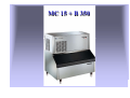
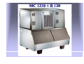
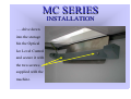
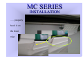
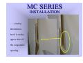
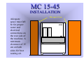
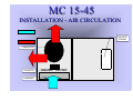
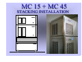
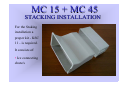
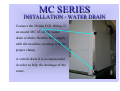
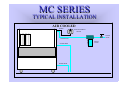
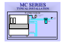
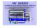
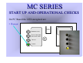
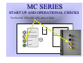
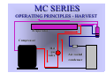
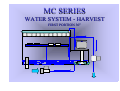
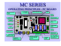
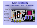
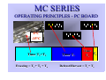
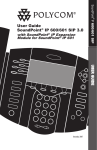
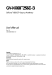
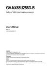
1
MC SERIES
CUBERS
TECHNICAL SERVICE TRAINING
Welcome to another Scotsman technical service presentation. This one will cover the MC
Series Ice Cube Machines models MC 15, MC 45 and MC 1210.
MC 15 + B 350
MC 45 + B 550
MC 1210 + B 120
MC SERIES
TOPICS
On the next slides are shown the following steps by steps
procedures:
• UNPACKING
• INSTALLATION
• START UP AND OPERATIONAL CHECKS
• OPERATING PRINCIPLES and COMPONENTS
• MAINTENANCE
• SERVICE ANALYSIS
MC SERIES
TOPICS
On the next slides are shown the following steps by steps
procedures:
• UNPACKING
• INSTALLATION
• START UP AND OPERATIONAL CHECKS
• OPERATING PRINCIPLES and COMPONENTS
• MAINTENANCE
• SERVICE ANALYSIS
MC SERIES
TOPICS
On the next slides are shown the following steps by steps
procedures:
• UNPACKING
• INSTALLATION
• START UP AND OPERATIONAL CHECKS
• OPERATING PRINCIPLES and COMPONENTS
• MAINTENANCE
• SERVICE ANALYSIS
MC SERIES
TOPICS
On the next slides are shown the following steps by steps
procedures:
• UNPACKING
• INSTALLATION
• START UP AND OPERATIONAL CHECKS
• OPERATING PRINCIPLES and COMPONENTS
• MAINTENANCE
• SERVICE ANALYSIS
MC SERIES
TOPICS
On the next slides are shown the following steps by steps
procedures:
• UNPACKING
• INSTALLATION
• START UP AND OPERATIONAL CHECKS
• OPERATING PRINCIPLES and COMPONENTS
• MAINTENANCE
• SERVICE ANALYSIS
MC SERIES
TOPICS
On the next slides are shown the following steps by steps
procedures:
• UNPACKING
• INSTALLATION
• START UP AND OPERATIONAL CHECKS
• OPERATING PRINCIPLES and COMPONENTS
• MAINTENANCE
• SERVICE ANALYSIS
MC SERIES
UNPACKING
MC SERIES
UNPACKING
The machines are supplied
in a carton box secured by
two plastic strips to a
wooden base. Check first
the outside conditions of
carton box and wooden
base then cut the two
plastic strips, remove the
tape and then the carton
box.
MC 45
MC SERIES
UNPACKING
Visually
inspect the
exterior of the
machine then
remove the
two side
panels………
……..and the
vertical ice
chute…..
MC SERIES
UNPACKING
…..unscrew
the unit frame
from the
wooden
base….
MC SERIES
UNPACKING
…..then remove
from the inside of
the machine all the
polystyrene
protection as well
as the….
…..the Optical Ice
Level Control
bracket and the
securing screws
and fiber washers.
MC SERIES
UNPACKING
The Modular Cuber
machines require for the
installation the use of a
companion storage bin
to store the ice
produced.
Storage bin required
are:
•B 350/550 for MC
15/45
•B 120 for MC 1210
B 550
MC SERIES
UNPACKING
Unpack the
storage bin and
visually inspect
the exterior then
remove from
the inside the
carton box
containing the
plastic deflector
as well as the
legs and rubber
strip.
MC SERIES
UNPACKING
Unloose the two screws holding
the drain fitting protection and
remove it
MC SERIES
INSTALLATION
MC SERIES
INSTALLATION
Install the four
legs sockets on
the bottom base
of the storage bin
as well as the
metal legs.
MC SERIES
INSTALLATION
Place the storage bin
in its definitive
location then install
on top of the same the
ice machine.
MC SERIES
INSTALLATION
Place
between
the
machine
and the
storage bin
the metal
bracket of
the Ice
Level
Control.
MC SERIES
INSTALLATION
Secure the
machine to
the storage
bin by means
of the two
screws
supplied.
MC SERIES
INSTALLATION
Insert the
two plastic
clips into the
two square
holes of the
S.S. bracket
then ….
MC SERIES
INSTALLATION
……cut the plastic strip
securing the Optical Ice
Level Control to the suction
line of the machine.
MC SERIES
INSTALLATION
Cut the rubber plug
located on the right side of
the ice chute rectangular
opening then….
MC SERIES
INSTALLATION
…..drive down
into the storage
bin the Optical
Ice Level Control
and secure it with
the two screws
supplied with the
machine.
MC SERIES
INSTALLATION
Install on the
upper front side
of the Ice Chute
rectangular
opening the Ice
Cubes plastic
deflector
supplied with
the storage bin
pay attention
to…..
MC SERIES
INSTALLATION
….. properly
hook it on
the front
edge.
MC SERIES
INSTALLATION
Install again
the vertical
ice chute
with its
cover…..
MC SERIES
INSTALLATION
….. paying
attention to
hook it on the
upper side of
the evaporator
opening .
MC SERIES
INSTALLATION
Check the data plate
of the machine
located on the rear
panel for correct
voltage as well as for
the proper wiring/fuse
size.
Remember that all
machines require a
solid earth wire.
MC SERIES
INSTALLATION
Check
Checkfor
forthe
thecorrect
correctwater
waterand
andambient
ambientconditions
conditionsthat
thatshould
shouldbe:
be:
•• Min.
Min. ambient
ambient temperature
temperature
10ºC
10ºC (50F)
(50F)
•• Max.
Max. ambient
ambienttemperature
temperature
40ºC
40ºC (100F)
(100F)
•• Min.
Min. water
water temperature
temperature
5ºC
5ºC (40F)
(40F)
•• Max.
Max. water
water temperature
temperature
35ºC
35ºC (90F)
(90F)
•• Min.
Min. water
water pressure
pressure
11bar
bar(14
(14 PSI)
PSI)
•• Max.
Max. water
water pressure
pressure
55bar
bar (70
(70 PSI)
PSI)
MC 15-45
INSTALLATION
Adequate
space must left
be for proper
water and
electrical
connections on
the rear side of
the machine. A
minimum
clearance of 15
cm on both
sides for best
routing air.
Min. space 15 cm
MC 15-45
INSTALLATION - AIR CIRCULATION
COLD
COLD AIR
AIR
HOT
HOT AIR
AIR
COMPRESSOR
FAN MOTOR
CONDENSER
ICE CHUTE
OPENING
MC 1210
INSTALLATION
Adequate space
must be left for
proper water and
electrical
connections on
the rear side of
the machine as
well as for best
routing air.
MC 1210
INSTALLATION - AIR CIRCULATION
COLD
COLD AIR
AIR
COMPRESSOR
HOT
HOT AIR
AIR
COMPRESSOR
FAN MOTOR
CONDENSER
ICE CHUTE
OPENING
ICE CHUTE
OPENING
MC 15 + MC 45
STACKING INSTALLATION
MC 15 + MC 45
STACKING INSTALLATION
For the Staking
installation a
proper kit - KSC
11 - is required.
It consists of:
• Ice connecting
chute/s
MC 15 + MC 45
STACKING INSTALLATION
• Ice connecting chute/s
• Interface PC Boards
made by SYEN…
….. and by Pro.El.Ind.
MC 15 + MC 45
STACKING INSTALLATION
• Ice connecting chute/s
• Interface PC Board
• Gasket
MC 15 + MC 45
STACKING INSTALLATION
• Ice connecting chute/s
• Interface PC Board
• Gasket
• Extension optical cable
MC 15 + MC 45
STACKING INSTALLATION
The Ice connecting
chute/s must be installed
through the bottom
rectangular opening of
the Top machine and it
connects the Ice Chute of
the upper machine with
the one of the bottom
machine.
MC 15 + MC 45
STACKING INSTALLATION
The Interface PC
Board must be
installed in the bottom
machine. The Optical
Ice Level Control
must be connected to
its inlet and, the two
Main PC Boards of
bottom and upper
machine to the outlets,
in order to switch off
both machines as soon
as the ice is stored
between the two eyes
of the optical ice level
control.
STACKING INSTALLATION
MAIN
MAIN PC
PC
BOARD
BOARD
INTERFACE
INTERFACE
PC
PC BOARD
BOARD
MAIN
MAIN PC
PC
BOARD
BOARD
ICE
ICE LEVEL
LEVEL
CONTROL
CONTROL
MC 15 + MC 45
STACKING INSTALLATION
ATTENTION!!!
ATTENTION!!!
It
It isis IMPERATIVE
IMPERATIVE that
that all
all the
the three
three PC
PC Boards
Boards ((
Ice
Ice Machines
Machines ones
ones ++ the
the Interface
Interface PC
PC Board)
Board)
MUST
MUST BE
BE of
of the
the same
same supplier
supplier (SYEN
(SYEN or
or
Pro.El.
Ind.).
Pro.El.Ind.).
The
The use
use of
of mixed
mixed PC
PC Boards
Boards can
can cause
cause the
the tripping
tripping
OFF
OFF of
of one
one or
or both
both machines
machines at
at Storage
Storage Bin
Bin Full
Full
with
with no
no ice
ice between
between the
the Optical
Optical Ice
Ice Level
Level control.
control.
MC 15 + MC 45
STACKING INSTALLATION
The gaskets must be
installed in the space
remaining between the
bottom base of the
upper machine and the
front panel of the
lower unit so to seal
completely any gap in
between.
MC 15 + MC 45
STACKING INSTALLATION
The Extension cable must be used
only when a current Electronic
machine is installed on top of an
Old Electro-mechanic unit when
the standard length of the cable of
the optical ice level control is too
short to connected it to the PC
Board.
The electrical connection must be
installed in a dry environment in
order to avoid any possibility of
“faulty contact”.
Electronic
Electro-mechanic
MC SERIES
INSTALLATION
Level the unit on both
directions front to
rear and right to left
side using the
adjustable legs.
MC SERIES
INSTALLATION - ELECTRICAL
Install, on the cable supply
with the machine, an
adaguate electrical plug
according to the local
standards and regulations.
Maximum voltage variation
should be ±10%.
Machine must be
individually fuse protected.
MC SERIES
INSTALLATION - WATER IN
Connect the water inlet 3/4”
male threat of the water inlet
solenoid valve to the water
supply line by means of the
rubber hose provided with
machine.
Install on water supply line
closed to the machine a water
valve (tap).
MC SERIES
INSTALLATION - WATER DRAIN
Connect the 20 mm O.D. fitting (2
on model MC 45) of the water
drain with the flexible hose supply
with the machine securing it by its
proper clamp.
A vented drain it is recommended
in order to help the drainage of the
water.
MC SERIES
TYPICAL INSTALLATION
AIR COOLED
POWER
HAND DISCONNECT
SWITCH
WATER
VALVE
WATER INLET
WATER
WATER DRAIN
WATER DRAIN
FILTER
MC SERIES
INSTALLATION - WATER IN
On the water cooled
version there is a
separate 3/4” male
thread water inlet fitting
connected directly to the
water regulating valve
that must be connect to
the water supply line by
means a second rubber
hose provided with
machine and.…..
MC SERIES
INSTALLATION - WATER OUT
…..a second separate drain
hose must be connected to
the outlet 3/4” male fitting
located on the upper side of
the water regulating valve.
MC SERIES
TYPICAL INSTALLATION
WATER COOLED
POWER
HAND DISCONNECT
SWITCH
WATER
WATER INLET
VALVE
WATER
WATER DRAIN
WATER DRAIN
FILTER
MC SERIES
START UP AND
OPERATIONAL
CHECKS
MC SERIES
START UP AND OPERATIONAL CHECKS
• Open the water tap/valve.
• Switch ON the power on the
electrical supply line.
MC SERIES
START UP AND OPERATIONAL CHECKS
The Ice Machine will start up automatically through the 5 minutes
“Water Filling Phase”.
MC SERIES
START UP AND OPERATIONAL CHECKS
The components energized
during the first 5’ are:
• PC Board
MC SERIES
START UP AND OPERATIONAL CHECKS
The components energized during
the first 5’ are:
• PC Board
• Water Inlet Solenoid Valve
MC SERIES
START UP AND OPERATIONAL CHECKS
The components energized
during the first 5’ are:
• PC Board
• Water Inlet Solenoid
Valve
• Water Drain/Purge
Solenoid Valve
MC SERIES
START UP AND OPERATIONAL CHECKS
The components energized
during the first 5’ are:
• PC Board
• Water Inlet Solenoid Valve
• Water Drain/Purge
Solenoid Valve
• Hot Gas Solenoid
Valve
MC SERIES
START UP AND OPERATIONAL CHECKS
During the first 5’ the water
goes through the Water Inlet
Valve then….
….flows into the small orifice
of the “Flow Control” located
on the outlet port of the same.
MC SERIES
START UP AND OPERATIONAL CHECKS
Following the copper inlet tube .... where it flows onto the plastic
the incoming water arrive on the evaporator platen dribbling down
upper side of the evaporator…. through the holes located on the
opposite side.
MC SERIES
START UP AND OPERATIONAL CHECKS
Dribbled water is
collected down into
the water sump
where is located
the overflow stand
pipe that assures
the proper water
level and quantity
for the next
freezing cycle.
MC SERIES
START UP AND OPERATIONAL CHECKS
After the first 5’ of water filling
phase the machine start up
automatically on freezing cycle
with the following electrical
components in operation:
• Compressor
MC SERIES
START UP AND OPERATIONAL CHECKS
• Compressor
• Water Pump
MC SERIES
START UP AND OPERATIONAL CHECKS
• Compressor
• Water Pump
• Fan Motor (on air cooled
version only)
MC SERIES
START UP AND OPERATIONAL CHECKS
• Compressor
• Water Pump
• Fan Motor (on air cooled
version only)
• Contactor
MC SERIES
START UP AND OPERATIONAL CHECKS
The operation of the
fan motor is controlled
by a condenser
temperature sensor
located within the fins
of condenser that
transmit a signal to the
PC Board to activate in
ON-OFF mode the fan
motor so to keep
between two pre-set
values the condenser
temperature and
pressure.
MC SERIES
START UP AND OPERATIONAL CHECKS
On PC Board the LED energized are:
• Power
PUSH
FREEZING CYCLE
TOO HI COND TEMP
TOO HI EVAP TEMP
BIN FULL
POWER
MC SERIES
START UP AND OPERATIONAL CHECKS
On PC Board the LED energized are:
• Power
• Freezing
PUSH
FREEZING CYCLE
TOO HI COND TEMP
TOO HI EVAP TEMP
BIN FULL
POWER
MC SERIES
START UP AND OPERATIONAL CHECKS
Water is
circulating by
the water pump
into the inverted
tin plated copper
molds of the
evaporator….
MC SERIES
START UP AND OPERATIONAL CHECKS
….while the
refrigerant is
flowing into
the serpentine
welded on the
upper side of
the tin plated
copper molds.
MC SERIES
START UP AND OPERATIONAL CHECKS
After
approximately 5
minutes after the
start up of the
freezing cycle, the
temperature of the
evaporator
serpentine drops
down to 0ºC….
0ºC
MC SERIES
START UP AND OPERATIONAL CHECKS
….with the blinking of the small RED LED located in the center of
PC Board.
MC SERIES
START UP AND OPERATIONAL CHECKS
Approximately 5
minutes the
temperature of the
evaporator
serpentine drops
down to - 15ºC….
-15ºC
MC SERIES
START UP AND OPERATIONAL CHECKS
….with the light ON steady of the small RED LED located in the
center of PC Board.
MC SERIES
START UP AND OPERATIONAL CHECKS
The machine remains in
the freezing cycle till its
completion for an
additional time
according to the set up of
the first four DIP
SWITCH of the PC
Board.
MC SERIES
START UP AND OPERATIONAL CHECKS
Once completed the freezing cycle
the machine enters into the
defrost or harvest cycle with the
following electrical components
in operation:
• Compressor
MC SERIES
START UP AND OPERATIONAL CHECKS
• Compressor
• Water Inlet Solenoid valve
MC SERIES
START UP AND OPERATIONAL CHECKS
• Compressor
• Water Inlet Solenoid
valve
• Water Drain/Purge
Solenoid Valve
MC SERIES
START UP AND OPERATIONAL CHECKS
• Compressor
• Water Inlet Solenoid valve
• Water Drain/Purge Solenoid
Valve
• Hot Gas Valve
MC SERIES
START UP AND OPERATIONAL CHECKS
According to the setting of
the DIP SWITCH no 9 the
Water Pump can remain in
operation to discharge the
water not used on the
previous freezing cycle
during the first....
MC SERIES
START UP AND OPERATIONAL CHECKS
….15” of the
harvest cycle when OFF = 15 seconds
the DIP SWITCH is
in OFF position or
30” when in ON
position.
ON = 30 seconds
MC SERIES
START UP AND OPERATIONAL CHECKS
The length of the
defrost or harvest
cycle is
SWITCH 5 AND 6
A
B
C
D
controlled by the
PC Board
according to the
setting of the DIP
SWITCH 5 and 6
and it is related
to …..
MC SERIES
START UP AND OPERATIONAL CHECKS
…..the time that the
machine takes to drop
the evaporating
temperature from 0ºC
to -15ºC (time T2) as
shown on the table.
LENGTH OF HARVEST CYCLE ACCORDING TO THE TIME
TO DROP THE EVAP. TEMPERATURE FROM 0ºC TO -13ºC
LENGTH
HARVEST
CYCLE
PROGRAMS
A
B
C
D
180”
165”
150”
135”
120”
105”
90”
Up to 6’
6’-7’
7’-8’
8’-9’
9’-10’
10’-12’
>12’
***
Up to 3’
3’-3’15’
3’15”-3’30”
3’30”-4’30”
430”-6’
>6’
Up to 9’
9’-10’
10’-11’
11’-12’
12’-13’
13’-15’
>15’
***
***
***
***
Up to 3’
3-4’
>4’
MC SERIES
START UP AND OPERATIONAL CHECKS
It’s possible to extend the length of the defrost cycle by means of
the DIP SWITCH 7 and 8 as per below chart.
DIP SWITCH
7
8
ON
ON
OFF
ON
ON
OFF
OFF
OFF
ADDITIONAL DEFROST TIME
0
30"
60"
90"
MC SERIES
START UP AND OPERATIONAL CHECKS
During the defrost
or harvest cycle
the combined
action of
refrigerant in Hot
Gas state and
incoming Water
are going to
partially melt the
ice cubes in
contact with the
tin plated copper
molts with the
dropping down of
the same through
the curtain.
MC SERIES
START UP AND OPERATIONAL CHECKS
Holding an
hand full of
ice cubes
between the
I/R Optical
Ice Level
Sensor during
the defrost
cycle it is
possible to
test its
operation.
MC SERIES
START UP AND OPERATIONAL CHECKS
The Bin Full YELLOW LED starts to blink.
PUSH
FREEZING CYCLE
TOO HI COND TEMP
TOO HI EVAP TEMP
BIN FULL
POWER
MC SERIES
START UP AND OPERATIONAL CHECKS
After 1 minute of continuous interruption of the infrared beam between
transmitter and received (Bin Full YELLOW LED always blinking) the
machine switch off at storage bin full with the light ON STEADY of
BIN FULL YELLOW LED.
PUSH
FREEZING CYCLE
TOO HI COND TEMP
TOO HI EVAP TEMP
BIN FULL
POWER
MC SERIES
OPERATING
PRINCIPLES
and
COMPONENTS
MC SERIES
OPERATING PRINCIPLES - FREEZE
Evaporator
Compressor
Hot
gas
valve
Air cooled
condenser
MC SERIES
OPERATING PRINCIPLES - HARVEST
Evaporator
Compressor
Hot
gas
valve
Air cooled
condenser
MC SERIES
WATER SYSTEM - FREEZE
MC SERIES
WATER SYSTEM - HARVEST
FIRST PORTION 30”
MC SERIES
WATER SYSTEM - HARVEST
SECOND PORTION
MC SERIES
OPERATING PRINCIPLES - PC BOARD
MICROPROCESSOR
MICROPROCESSOR
EPROM
EPROM
0°C-BLINKING
0°C-BLINKING
-13°C-STEADY
-13°C-STEADY
RESET
RESETPUSH
PUSHBUTTON
BUTTON
TRIAC
TRIAC
FUSE
FUSE
FREEZING
FREEZING
TRANSFORMER
TRANSFORMER
ALARM
ALARM
WATER
WATERPUMP
PUMP
RELAY
RELAY
BIN
BINFULL
FULL
COMPRESSOR
COMPRESSOR
RELAY
RELAY
POWER
POWER
FUSE
FUSE
I/R ADJUSTER
I/R ADJUSTER
EVAPORATOR
EVAPORATOR
SENSOR
SENSORSOCKET
SOCKET
CONDENSER
CONDENSER
SENSOR
SENSORSOCKET
SOCKET
RESISTANCE
RESISTANCE
VARISTOR
VARISTOR
OPTICAL
OPTICALICE
ICELEVEL
LEVEL
CONTROLSENSOR
CONTROLSENSOR
SOCKET
SOCKET
TERMINAL
TERMINAL
BOARD
BOARD
HOT GAS, WATER
HOT GAS, WATER
INLET AND PURGE
INLET AND PURGE
VALVES RELAY
VALVES RELAY
MC SERIES
OPERATING PRINCIPLES - PC BOARD
SWITCH
SWITCH55AND
AND66
LENGTH
LENGTHOF
OFTHE
THE
HARVEST
HARVESTCYCLE
CYCLE
ACCORDING
ACCORDINGTO
TOTHE
THE
TIME
TIMETT2
2
SWITCH
SWITCH1,1,2,2,33AND
AND44
SETTING
SETTINGOF
OFTHE
THE
TIMED
TIMEDPORTION
PORTIONOF
OF
FREEZING
FREEZINGCYCLE
CYCLE
SWITCH
SWITCH77AND
AND88
EXTENTION
EXTENTIONTIME
TIMEOF
OF
HARVEST
HARVESTCYCLE
CYCLEBY
BY0”,
0”,
30”,
60”
OR
90”
30”, 60” OR 90”
SWITCH
SWITCH99
OPERATING
OPERATINGTIME
TIME
OF
OFWATER
WATERPUMP
PUMP
DURING
HARVEST
DURING HARVEST
OFF
OFF==15”
15”
ON
ON==30”
30”
SWITCH
SWITCH10
10
CONDENSER
CONDENSER
SAFETY
SAFETYCUT
CUTOUT
OUT
TEMPERATURE
TEMPERATURE
(60ºC
(60ºCWATER
WATER- OFF
OFFAND
AND70ºC
70ºC
AIR
AIR- -ON)
ON)
MC SERIES
OPERATING PRINCIPLES - PC BOARD
Time T1
From start
up of
freezing
cycle till the
blinking of
0°C Red
LED
MC SERIES
OPERATING PRINCIPLES - PC BOARD
Time T2
From
blinking of
Red LED
till the light
ON steady
of -15°C
Red LED
MC SERIES
OPERATING PRINCIPLES - PC BOARD
Time Ta
LENGTH OF TIMED PORTION OF FREEZING
CYCLE – FIRST 4 SWITCHES
Added time controlled by
the PC Board according
25’
23’
21’
to the setting of the DIP
SWITCH 1, 2, 3 and 4.
19’
17’
13’
11’
7’
5’
15’
9’
3’
MC SERIES
OPERATING PRINCIPLES - PC BOARD
Time Ts
Harvest Time TS is
controlled by the PC
Board and it is inversely
proportional to the Time
T2 of the Freeze Cycle
(from 0ºC to -13ºC) as per
the combination A of the
Table.
Time TS is NOT
adjustable.
LENGTH OF HARVEST CYCLE ACCORDING TO THE TIME
TO DROP THE EVAP. TEMPERATURE FROM 0ºC TO -13ºC
LENGTH
HARVEST
CYCLE
PROGRAMS
A
B
C
D
180”
165”
150”
135”
120”
105”
90”
Up to 6’
6’-7’
7’-8’
8’-9’
9’-10’
10’-12’
>12’
***
Up to 3’
3’-3’15’
3’15”-3’30”
3’30”-4’30”
430”-6’
>6’
Up to 9’
9’-10’
10’-11’
11’-12’
12’-13’
13’-15’
>15’
***
***
***
***
Up to 3’
3-4’
>4’
MC SERIES
START UP AND OPERATIONAL CHECKS
It’s possible to extend the length of the harvest cycle (Te) by
means of the DIP SWITCH 7 and 8 as per below chart.
DIP SWITCH
7
8
ON
ON
OFF
ON
ON
OFF
OFF
OFF
ADDITIONAL DEFROST TIME
0
30"
60"
90"
MC SERIES
OPERATING PRINCIPLES - PC BOARD
0°C
0°C
-15°C
-15°C
Time T1+T2
Freezing = T1 + T2 + Ta
Time Ta
Time
Te
Ts
Defrost/Harvest = Ts + Te
MC SERIES
OPERATING PRINCIPLES - ALARM
TOO HI COND. TEMPERATURE
Whenever the
condensing temperature
rise up to 70ºC (air
cooled version) or 60ºC
(water cooled version)
the PC Board will
switch OFF
immediately the entire
machine with the light
ON of the Red
ALARM LED.
FREEZING CYCLE
TOO HI COND TEMP
TOO HI EVAP TEMP
BIN FULL
POWER
MC SERIES
OPERATING PRINCIPLES - ALARM
TOO HI EVAP. TEMPERATURE
In case the evaporating
temperature remains
higher then 0ºC after 15
minutes from the
beginning of the freezing
cycle the PC Board will
switch OFF immediately
the entire machine with
the blinking of the Red
ALARM LED.
FREEZING CYCLE
TOO HI COND TEMP
TOO HI EVAP TEMP
BIN FULL
POWER
MC SERIES
OPERATING PRINCIPLES - ALARM
CONDENSER SENSOR OUT OF ORDER
In case both the
Red and Yellow
LED are light
FREEZING CYCLE
ON steady the
TOO HI COND TEMP
TOO HI EVAP TEMP
condenser sensor is
BIN FULL
out of order and
need to be
replaced.
POWER
MC SERIES
OPERATING PRINCIPLES - ALARM
EVAPORATOR SENSOR OUT OF ORDER
In case both the
Red and Yellow
LED are
blinking the
evaporator sensor
is out of order and
need to be
replaced.
FREEZING CYCLE
TOO HI COND TEMP
TOO HI EVAP TEMP
BIN FULL
POWER
MC SERIES
OPERATING PRINCIPLES - BIN FULL
As soon as the
ice cubes are in
between the
transmitter and
receiver sensor
of the Optical
Ice Level
Control….
MC SERIES
OPERATING PRINCIPLES - BIN FULL
….immediately
the Bin Full
FREEZING CYCLE
Yellow LED
TOO HI COND TEMP
TOO HI EVAP TEMP
starts to blink
BIN FULL
and after…..
POWER
MC SERIES
OPERATING PRINCIPLES - BIN FULL
….one minute
the PC Board
FREEZING CYCLE
switch OFF the
TOO HI COND TEMP
entire machine
with the light
ON of BIN
FULL Yellow
LED.
TOO HI EVAP TEMP
BIN FULL
POWER
MC SERIES
OPERATING PRINCIPLES - BIN FULL
When ice is
scooped out
from the
storage bin….
MC SERIES
OPERATING PRINCIPLES - BIN FULL
…. after six-seven
seconds the machine
restart in the
FREEZING CYCLE
operation from the
TOO HI COND TEMP
beginning of the
freezing cycle when
the evaporator
temperature is
above 0ºC ....
TOO HI EVAP TEMP
BIN FULL
POWER
MC SERIES
OPERATING PRINCIPLES - BIN FULL
….….or from the
harvest cycle when
the evaporating
FREEZING CYCLE
temperature is
TOO HI COND TEMP
TOO HI EVAP TEMP
below 0ºC in order
BIN FULL
to avoid any
possibility of double
freezing cycle.
POWER
MC SERIES
OPERATING PRINCIPLES - POWER OFF
In case of black out in power the machine re-starts (when power
is back) through the 5 minutes water filling phase with the
compressor:
ON
When the evaporator temperature is < 0ºC
OFF
When the evaporator temperature is > 0ºC
MC SERIES
OPERATING PRINCIPLES - POWER OFF
In case of black out in power the machine re-starts (when power
is back) through the 5 minutes water filling phase with the
compressor:
ON
When the evaporator temperature is < 0ºC
OFF When the evaporator temperature is > 0ºC
MC SERIES
COMPONENTS - REFRIGERANT SYSTEM
LOCATION OF REFRIGERANT COMPONENTS
The components of the refrigerant
system of the MC series Models are
composed by:
• COMPRESSOR
MC SERIES
COMPONENTS - REFRIGERANT SYSTEM
LOCATION OF REFRIGERANT COMPONENTS
• COMPRESSOR
• CONDENSER
MC SERIES
COMPONENTS - REFRIGERANT SYSTEM
LOCATION OF REFRIGERANT COMPONENTS
• COMPRESSOR
• CONDENSER
• EVAPORATOR
MC SERIES
COMPONENTS - REFRIGERANT SYSTEM
LOCATION OF REFRIGERANT COMPONENTS
• COMPRESSOR
• CONDENSER
• EVAPORATOR
• SUCTION LINE AND
CAPILLARY TUBE
MC SERIES
COMPONENTS - REFRIGERANT SYSTEM
LOCATION OF REFRIGERANT COMPONENTS
• COMPRESSOR
• CONDENSER
• EVAPORATOR
• SUCTION LINE AND
CAPILLARY TUBE
• DRIER
MC SERIES
COMPONENTS - REFRIGERANT SYSTEM
LOCATION OF REFRIGERANT COMPONENTS
• COMPRESSOR
• CONDENSER
• EVAPORATOR
• SUCTION LINE AND CAPILLARY
TUBE
• DRIER
• HOT GAS VALVE
MC SERIES
COMPONENTS - WATER SYSTEM
The components of the water system
of the MC Series Models are
composed by:
• WATER INLET VALVE
MC SERIES
COMPONENTS - WATER SYSTEM
• WATER INLET VALVE
• WATER SUMP
MC SERIES
COMPONENTS - WATER SYSTEM
• WATER INLET VALVE
• WATER SUMP
• WATER PUMP
MC SERIES
COMPONENTS - WATER SYSTEM
• WATER INLET
VALVE
• WATER SUMP
• WATER PUMP
• SPRAY BAR
MC SERIES
COMPONENTS - WATER SYSTEM
• WATER INLET
VALVE
• WATER SUMP
• WATER PUMP
• SPRAY BAR
• OVERFLOW
MC SERIES
COMPONENTS - WATER SYSTEM
• WATER INLET
VALVE
• WATER SUMP
• WATER PUMP
• SPRAY BAR
• OVERFLOW
• WATER DRAIN
VALVE
MC SERIES
COMPONENTS - ELECTRONIC CONTROLS
The components of
the Electronic
System of the MC
Series Models are
composed by:
• PC BOARD
MC SERIES
COMPONENTS - ELECTRONIC CONTROLS
• PC BOARD
• EVAPORATOR
SENSOR
MC SERIES
COMPONENTS - ELECTRONIC CONTROLS
• PC BOARD
• EVAPORATOR
SENSOR
• CONDENSER
SENSOR
MC SERIES
COMPONENTS - ELECTRONIC CONTROLS
• PC BOARD
• EVAPORATOR
SENSOR
• CONDENSER
SENSOR
• OPTICAL ICE
LEVEL
CONTROL
MC SERIES
END FIRST
HALF