1
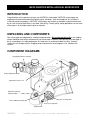
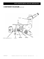
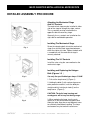
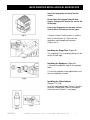
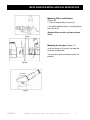
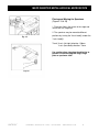
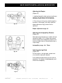
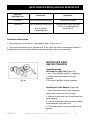
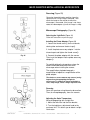
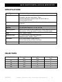
MEC2
INVERTED METALLURGICAL
MICROSCOPE
MANUAL
73 Mall Drive, Commack, NY 11725 • 631-543-2000 (P) • 631-589-6975 (F)
www.unitronusa.com • [email protected]
MEC2 INVERTED METALLURGICAL MICROSCOPE
CONTENTS
SAFETY NOTES .................................................................................................................. 3
CARE AND MAINTENANCE ................................................................................................ 3
INTRODUCTION .................................................................................................................. 4
UNPACKING AND COMPONENTS ..................................................................................... 4
COMPONENT DIAGRAMS ............................................................................................... 4-5
ASSEMBLY .......................................................................................................................... 5
DETAILED ASSEMBLY PROCEDURE ................................................................................ 6
ADJUSMENT AND OPERATION
TURNING ON THE LAMP ............................................................................................. 10
ADJUSTING THE BRIGHTNESS .................................................................................. 10
ADJUSTING THE TENSION ADJUSTMENT COLLAR ................................................. 10
ADJUSTING THE ILLUMINATION ................................................................................ 11
PLACING AND MOVING THE SPECIMEN ................................................................... 12
ADJUSTING THE DIOPTER ......................................................................................... 13
ADJUSTING THE INTERPUPILLARY DISTANCE ....................................................... 13
SWITCHING THE LIGHT PATH.................................................................................... 13
MICROSCOPE VIDEO AND PHOTOGRAPHY ............................................................ 14
SPECIFICATIONS .............................................................................................................. 16
TROUBLESHOOTING........................................................................................................ 17
MAINTENANCE.................................................................................................................. 18
SERVICE ............................................................................................................................ 18
WARRANTY ....................................................................................................................... 12
UNITRON®
73 Mall Drive, Commack, NY 11725 • 631-543-2000 • www.unitronusa.com
2
MEC2 INVERTED METALLURGICAL MICROSCOPE
SAFETY NOTES
1. Open the shipping carton carefully to prevent any accessory, i.e. objectives or eyepieces, from
dropping and being damaged.
2. Keep the instrument out of direct sunlight, high temperature or humidity, and dusty environments.
3. If any specimen solutions or other liquids splash onto the stage, objective or any other component,
disconnect the power cord immediately and wipe up the spillage. Otherwise, the instrument may be
damaged.
4.
LAMP REPLACEMENT -- CAUTION: the glass envelope of the lamp may be extremely
hot. DO NOT attempt to change the lamp before it is completely cooled or without
wearing adequate skin protection.
5. All electrical connectors (power cord) should be inserted into an electrical surge protector to prevent
damage due to voltage fluctuations.
6.
FUSE REPLACEMENT -- For safety when replacing the fuse (ONLY replace with the
same size, type and rating of original fuse), be sure the main switch is in the off position,
disconnect the power cord from outlet, and replace the fuse. Reconnect the power cord
and turn unit on.
7. Confirm that the input voltage indicated on your microscope corresponds to your line voltage. The
use of a different input voltage other than indicated will cause severe damage to the microscope.
NOTE: Always plug the stereomicroscope power cord into a suitable grounded electrical outlet. A
grounded 3-wire cord is provided.
CARE AND MAINTENANCE
1. Do not attempt to disassemble any component including eyepieces, objectives or focusing assembly.
2. Keep the instrument clean; remove dirt and debris regularly. Accumulated dirt on metal surfaces
should be cleaned with a damp cloth. More persistent dirt should be removed using a mild soap
solution. Do not use organic solvents for cleansing.
3. The outer surface of the optics should be inspected and cleaned periodically using an air stream from
an air bulb. If dirt remains on the optical surface, use a soft, lint free cloth or cotton swab dampened
with a lens cleaning solution (available at camera stores). All optical lenses should be swabbed using
a circular motion. A small amount of absorbent cotton such as a Q-tip or cotton swab, makes a useful
tool for cleaning recessed optical surfaces. Avoid using an excessive amount of solvents as this may
cause problems with optical coatings or cemented optics or the flowing solvent may pick up grease
making cleaning more difficult.
4. Store the instrument in a cool, dry environment. Cover the microscope with the dust cover when not
in use.
5. UNITRON® microscopes are precision instruments which require periodic servicing to maintain
proper performance and to compensate for normal wear. A regular schedule of preventative
maintenance by qualified personnel is highly recommended. Your authorized UNITRON® distributor
can arrange for this service.
UNITRON®
73 Mall Drive, Commack, NY 11725 • 631-543-2000 • www.unitronusa.com
3
MEC2 INVERTED METALLURGICAL MICROSCOPE
INTRODUCTION
Congratulations on the purchase of your new UNITRON® microscope. UNITRON® microscopes are
engineered and manufactured to the highest quality standards. Your microscope will last a lifetime if
used and maintained properly. UNITRON® microscopes are carefully assembled, inspected and tested
by our staff of trained technicians in our New York facility. Careful quality control procedures ensure each
microscope is of the highest quality prior to shipment.
UNPACKING AND COMPONENTS
Your microscope arrived packed in a molded shipping carton. Do not discard the carton: the shipping
carton should be retained for reshipment of your microscope if needed. Avoid placing the microscope in
dusty surroundings or in high temperature or humid areas as mold and mildew can form. Carefully
remove the microscope from the shipping carton and place the microscope on a flat, vibration-free
surface.
COMPONENT DIAGRAMS
Interpupillary Distance Indicator
Diopter Adjustment Collar
Light Path Selector Lever
Illumination Intensity
Adjustment Dial
Fine Focusing Knob
Tension Adjustment Collar
Coarse Focusing Knob
On/Off Switch
UNITRON®
73 Mall Drive, Commack, NY 11725 • 631-543-2000 • www.unitronusa.com
4
MEC2 INVERTED METALLURGICAL MICROSCOPE
COMPONENT DIAGRAMS (continued)
Analyzer
Condenser Adjsutment Lever
UNITRON®
Polarizer
Aperture
Diaphragm
Field
Diaphragm
Filter
73 Mall Drive, Commack, NY 11725 • 631-543-2000 • www.unitronusa.com
5
MEC2 INVERTED METALLURGICAL MICROSCOPE
DETAILED ASSEMBLY PROCEDURE
Attaching the Mechanical Stage
And X-Y Controls
The mechanical stage may be installed in either
side of the stage to enlarge the stage surface.
The x-y controls must be installed on the
opposite side of theauxiliary stage.
Generally, the x-y controls are installed on the
right side for comfortable operation.
Installing The Mechanical Stage
Fig. 1
Screw the clamping bolts into to the mechanical
stage, then into the fixed stage from below on
either the right or left side. Tighten the bolts with
a screwdriver until the mechanical stage is
securely attached.
Installing The X-Y Controls
Install the ruler using the same method as the
mechanical stage.
Installing and Replacing the Halogen
Bulb (Figures 1-3)
Fig. 2
Use only the specified halogen lamp: 6V 30W
1. Pull out the lamp house① (Figure 1)
2. Holding the bulb ① with a piece of gauze or
other protective material, insert the bulb pins
straight and fully into the pin holes③ on the
lamp house. (Figure 2)
CAUTION: The bulb, lamp housing and
nearby parts will be very hot during usage.
Fig. 3
UNITRON®
3. When replacing the lamp, turn the main
switch to “O (off) and remove the power cord.
Allow the lamp, lamp house and adjacent areas
to sufficiently cool before handling. The lamp
can become very hot and will cause burns.
73 Mall Drive, Commack, NY 11725 • 631-543-2000 • www.unitronusa.com
6
MEC2 INVERTED METALLURGICAL MICROSCOPE
Insert the lamp gently but firmly into the
socket.
Do not touch the halogen bulb with bare
fingers. Doing so will shorten the service life
of the lamp.
If you leave fingerprints on the lamp surface,
clean it with a soft cloth or lint free paper.
4. Align the socket ① with the pins ③, and the
Fig. 4
bolts ② with the jacks ④. Then insert the
lamphouse cover completely into place.
(Figures 3 & 4)
Installing the Stage Plate (Figure 5)
The stage plate ① is installed by placing it in the
center of fixed stage.
Fig. 5
Installing the Eyepieces (Figure 6)
1. Remove the protective caps on the eyepiece
tubes.
2. Insert the eyepieces into eyepiece tubes until
they are completely inserted.
Fig. 6
Installing the Video Adapter
(Figures 7, 8, & 9)
Insert the video adapter tube (Figure 7) into the
trinocular viewing head (Figure 8) and tighten
the thumb screw (Figure 9 – next page).
Fig. 8
Fig. 7
UNITRON®
73 Mall Drive, Commack, NY 11725 • 631-543-2000 • www.unitronusa.com
7
MEC2 INVERTED METALLURGICAL MICROSCOPE
Mounting Filters and Polarizer
(Figure 10)
1. Insert a standard filter(s) into slot (1)
2. For polarized observation, insert the polarizer
filter into slot (2).
Standard filters are blue, yellow and green
filters
Fig. 9
Mounting the Analyzer (Figure 11)
Insert the analyzer (3) into the slot under the
trinocular viewing head.
The analyzer may be used alone or with the
polarizer.
Fig. 10
Fig. 11
UNITRON®
73 Mall Drive, Commack, NY 11725 • 631-543-2000 • www.unitronusa.com
8
MEC2 INVERTED METALLURGICAL MICROSCOPE
Connecting the Power Cord
(Figures 12, 13 & 14)
The electric cord should never be bent,
twisted, crushed or subjected to stress.
1. Set the main switch① to “O” (off) before
connecting the power cord.
2. Insert the power cord into the receptacle②.
Fig. 12
3. Insert the BNC cord plug (3) into the BNC
connector (4).
Ensure the power cord is connected to a
properly grounded electrical outlet.
Replacing the Fuse (Figures 12 & 13)
Fig. 13
Ensure the main switch① is set to “O” (Off) and
the power cord is disconnected before replacing
the fuse. With a flat-head screwdriver, remove
the fuse holder (5), replace with a new fuse,
then re-install the fuse holder.
Fuse rating: 250V, 500mA
Connecting the Power Cord
(Figure 14)
Insert the power cord (6) into a properly
grounded 3-prong electrical outlet (7).
Fig. 14
UNITRON®
73 Mall Drive, Commack, NY 11725 • 631-543-2000 • www.unitronusa.com
9
MEC2 INVERTED METALLURGICAL MICROSCOPE
ADJUSTMENT
AND OPERATION
Turning On The Lamp
(Figure 15)
Connect the power cord, then set the main
switch① on the side of the base to the “on”
Fig. 15
position (“-”).
Adjusting The Brightness
(Figure 16)
Rotate the brightness adjustment knob (2)
clockwise to increase the brightness.
Conversely, rotating the knob decreases the
brightness.
Using the lamp at its lowest acceptable
intensity will increase the life of the lamp.
Fig. 16
Adjusting the Tension
Adjustment Collar
(Figure 17)
The tension of the coarse focusing knob
(3) has already been properly adjusted.
Use the supplied tension adjustment wrench to
adjust the tension adjustment collar (4).
Fig. 17
Rotating the collar clockwise increases the
tension on the coarse focusing knob. A counterclockwise rotation will decrease the tension on
the coarse focus knob.
The coarse focusing knob is too loose if the
nosepiece descends on its own or if the
specimen loses its focus shortly after focusing
with the fine focus knob (5). Adjust the tension
adjustment collar so these do not occur.
UNITRON®
73 Mall Drive, Commack, NY 11725 • 631-543-2000 • www.unitronusa.com
10
MEC2 INVERTED METALLURGICAL MICROSCOPE
Adjusting the Illumination
(Figure 18)
1. Make sure the field of view is bright and
evenly illuminated, and has no filament shadow.
If there is filament shadow, adjust the condenser
adjustment knob③ to its proper position.
Fig. 18
2. To obtain a clear, sharp image, adjust the
field iris diaphragm① and aperture iris
diaphragm (2) to their proper positions. One or
both diaphragms may need to be adjusted to
obtain the sharpest image.
Aperture Iris Diaphragm: The aperture iris diaphragm is not used to control the brightness of the
image. It controls the aperture angle of the incident rays. The diaphragm is not adjusted properly
until the incident rays just fill the objective lens. At this position, the contrast and sharpness of the
image will be the best. The aperture diaphragm should be re-adjusted when changing objectives.
Field Iris Diaphragm: The field iris diaphragm is used to control the size of the field of view,
reduce the reflected rays and glare, thereby increasing the contrast of the image. Generally, the field
iris diaphragm is at the proper setting when the rays just fill the field of view of the eyepieces.
.
UNITRON®
73 Mall Drive, Commack, NY 11725 • 631-543-2000 • www.unitronusa.com
11
MEC2 INVERTED METALLURGICAL MICROSCOPE
Placing and Moving the Specimen
(Figures 19 & 20)
1. Place the slide in the center of the stage and
secure with the stage clip.
2. The specimen may be moved to different
Fig. 19
positions by turning the X-axis knob① and/or the
Y-axis knob②.
Travel: X-axis (left-right) direction: 120mm
Y-axis (front-back) direction: 78mm
Use caution when changing the objective to
prevent it from touching the stage, stage
plate or specimen slide.
Fig. 20
UNITRON®
73 Mall Drive, Commack, NY 11725 • 631-543-2000 • www.unitronusa.com
12
MEC2 INVERTED METALLURGICAL MICROSCOPE
Adjusting the Diopter
(Figure 21)
1. Looking through the right ocular only with your
right eye, use the coarse and fine focusing
adjustment knobs to focus on the specimen.
2. Then with your left eye only, look through the
left ocular. If the image is not sharp, rotate the
Fig. 21
diopter adjustment ring① to focus on the
specimen.
Diopter adjustment range: ±5
Adjusting the Interpupillary Distance
(Figure 22)
While observing with both eyes, hold the left and
right prism holders (2 & 3), rotate them around
the axis to adjust the interpupillary distance until
the left and right fields of view coincide to form a
single image.
Interpupillary range:48~75mm
Fig. 22
Switching the Light Path
(Figure 23)
Pull out or push in the light path selector lever
(4) to select the light path required.
For the binocular observation, push the lever in
completely .For video or microphotography, pull
the lever out completely.
Fig. 23
UNITRON®
73 Mall Drive, Commack, NY 11725 • 631-543-2000 • www.unitronusa.com
13
MEC2 INVERTED METALLURGICAL MICROSCOPE
Light Path
Selecting Lever
Illumination
Application
Pushed In
100% for binocular observation
Binocular observation
Pulled Out
20% for binocular observation
Binocular observation and video
(CCTV) or microphotography
simultaneously
80% for video or
microphotography
Polarization Observation
1. Insert the polarizer and analyzer as described on page 8 (Figures 10 & 11).
2. The analyzer hand wheel can be rotated from 0 °to 90°. When the field of view becomes the darkest,
the polarization position has been obtained and polarized observation can be performed.
MICROSCOPE VIDEO
AND PHOTOGRAPHY
Video Microscopy
Selecting the Light Path (Figure 24)
1. Push in the light path selector (1) completely.
2. Using binocular observation, focus your
specimen.
Fig. 24
3. Pull out the light path selector completely.
Installing the Video Adapter (Figure 25)
1. Loosen the thumb screw ① on the trinocular
viewing tube, and remove the dust cap②.
2. Remove the dust covers on the both ends of the
video adapter③.
3. Insert the flanged end into the trinocular viewing
head and tighten the thumb screw.
4. The threaded video C-mount should be facing
upwards.
UNITRON®
73 Mall Drive, Commack, NY 11725 • 631-543-2000 • www.unitronusa.com
14
MEC2 INVERTED METALLURGICAL MICROSCOPE
Focusing (Figure 25)
Observing through binocular position, focus the
specimen until a sharp image is obtained. Then
check the image on the monitor to which the
microscope is connected. If the image is not sharp,
rotate the video adapter (4) until the image is sharp.
Microscope Photography (Figure 26)
Selecting the Light Path (Figure 24)
Follow the instructions on previous page
Installing the Photo Adapter (Figure 26)
1. Loosen the thumb screw ① on the trinocular
viewing tube and remove the dust cap②.
2. Install the photo accessory adapter into the
trinocular port and tighten the thumb screw①.
Fig. 25
3. Connect the photo adapter with the camera.
Then insert the adapter into the photo accessory
adapter③.
To avoid disturbing the image focus, place the
camera viewfinder toward the front of the
microscope when installing the camera.
The magnification of photomicrograph =
magnification of objective x magnification of the
photo adapter.
The shutter on some cameras may cause a jarring
impact when photographing through the
microscope. To weaken the impact and obtain a
clear, sharp image, select a longer exposure time.
Focusing
Focus the specimen using binocular observation.
Then, for microphotography, focus the camera.
Adjusting the Color Temperature
When photographing with sunlight film:
1. Mount the blue filter into the filter bracket.
Fig. 26
UNITRON®
2. Turn the brightness adjustment knob to the
maximum limit. This allows you to obtain sunlight
illumination.
73 Mall Drive, Commack, NY 11725 • 631-543-2000 • www.unitronusa.com
15
MEC2 INVERTED METALLURGICAL MICROSCOPE
SPECIFICATIONS
Optical System
Infinity Optical System
Viewing Tube
Siedentopf style; Trinocular Tube; Inclined 30º; Diopter Range: ±5;
Interpupillary distance range: 48mm -75mm
Standard configuration light distribution: Binocular 100% or
Binocular/photo 20%/80%
Eyepiece
Extra Wide Field 10x with 20mm field of view with diopter adjustment and
eyeguards
Nosepiece
Quintuple nosepiece with positive click stops
Objective
Plan achromatic objectives: 5x, 10x, 20x, 40x
Focusing System
Coaxial coarse and fine focusing adjustment; Vertical objective movement;
Coarse focus: 377mm per roation; Fine focus: 0.2mm per rotation
Stage
Area: 160mm x 250mm
Mechanical Ruler
X/Y Coaxial Control; Right hand low position
Movement range: 120mm x 78mm
Illumination
6 volt 30 watt halogen; variable intensity;
External lamp housing for Kohler illumination
Filters
Blue, yellow, green and ground glass
OBJECTIVES
Magnification
Aperture Number
(N.A.)
Working Distance
(mm)
Conjugate Distance
(mm)
5x
0.12
15.4
8
10x
.25
11
8
20x
0.4
6
8
40x
0.6
3.7
8
UNITRON®
73 Mall Drive, Commack, NY 11725 • 631-543-2000 • www.unitronusa.com
16
MEC2 INVERTED METALLURGICAL MICROSCOPE
TROUBLESHOOTING
Under certain conditions, performance of this unit may be adversely affected by factors other than
defects. If a problem occurs, please review the following list and take remedial action as needed. If you
cannot solve the problem after checking the entire list, please contact your local dealer for assistance.
OPTICAL
PROBLEM
CAUSE
CORRECTIVE MEASURE
Darkness at the periphery or uneven
brightness in the field of view
Revolving nosepiece not in click
stop position
Turn the nosepiece to click-stop
position so the objective is in the
optical path
Dirt or dust on the viewfield
Dirt or dust on the lens, eyepiece,
condenser, objective, collector lens
or specimen
Clean the lens
Poor image quality
Condenser aperture is closed or
open too much
Open or close properly
Condenser is positioned too low
Position the condenser at the upper
limit
Specimen rises from stage surface
Secure the specimen with the holder
Revolving nosepiece is not in the
click-stop position
Turn the nosepiece to the click-stop
position
Blue filter not used
Use daylight blue filter
Lamp intensity is too low
Adjust the light intensity by turning
the intensity control dial
Image is too bright
Lamp intensity is too high
Adjust the light intensity by turning
the intensity control dial
Insufficient brightness
Lamp intensity is too low
Adjust the light intensity by turning
the intensity control dial
Aperture diaphragm closed too far
Open to the proper setting
Condenser position is too low
Position the condenser to the upper
limit
No electrical power
Check power cord connection
Lamp bulb burnt out
Replace bulb
Fuse blown out
Replace fuse
Slippage of focus when using the
coarse focusing knob
Tension adjustment is set too low
Increase the tension on the focusing
knobs
Fine focus is ineffective
Tension adjustment is set too high
Loosen the tension on the focusing
knobs
IMAGE PROBLEMS
Image moves while focusing
Image tinged yellow
Lamp does not light when switched
on
UNITRON®
73 Mall Drive, Commack, NY 11725 • 631-543-2000 • www.unitronusa.com
17
MEC2 INVERTED METALLURGICAL MICROSCOPE
MAINTENANCE
Please remember to never leave the microscope with eyepieces removed and always protect the
microscope with the dust cover when not in use.
SERVICE
UNITRON® microscopes are precision instruments which require periodic servicing to keep them
performing properly and to compensate for normal wear. A regular schedule of preventative maintenance
by qualified personnel is highly recommended. Your authorized UNITRON® distributor can arrange for
this service. Should unexpected problems be experienced with your instrument, proceed as follows:
1. Contact the UNITRON® distributor from whom you purchased the microscope. Some
problems can be resolved simply over the telephone.
2. If it is determined that the microscope should be returned to your UNITRON® distributor or to
UNITRON® for warranty repair, pack the instrument in its original Styrofoam shipping carton. If you no
longer have this carton, pack the microscope in a crush-resistant carton with a minimum of three inches
of a shock absorbing material surrounding it to prevent in-transit damage. The microscope should be
wrapped in a plastic bag to prevent Styrofoam dust from damaging the microscope. Always ship the
microscope in an upright position; NEVER SHIP A MICROSCOPE ON ITS SIDE. The microscope or
component should be shipped prepaid and insured.
LIMITED MICROSCOPE WARRANTY
This microscope is warranted to be free from defects in material and workmanship for a period of five (5) years for
mechanical and optical components and one (1) year for electrical components from the date of invoice to the
original (end user) purchaser. This warranty does not cover damage caused in-transit, misuse, neglect, abuse or
damage resulting from improper servicing or modification by other then UNITRON® approved service personnel.
This warranty does not cover any routine maintenance work or any other work, which is reasonably expected to be
performed by the purchaser. Normal wear is excluded from this warranty. No responsibility is assumed for
unsatisfactory operating performance due to environmental conditions such as humidity, dust, corrosive chemicals,
deposition of oil or other foreign matter, spillage or other conditions beyond the control of Unitron Ltd. This
warranty expressly excludes any liability by Unitron Ltd. for consequential loss or damage on any grounds, such as
(but not limited to) the non-availability to the End User of the product(s) under warranty or the need to repair work
processes. Should any defect in material, workmanship or electronic component occur under this warranty contact
your UNITRON® distributor or UNITRON® at (631) 543-2000. This warranty is limited to the continental United
States of America. All items returned for warranty repair must be sent freight prepaid and insured to Unitron Ltd.,
73 Mall Drive, Commack, NY 11725 – USA. All warranty repairs will be returned freight prepaid to any destination
within the continental United States of America. For all foreign warranty repairs, return freight charges are the
responsibility of the individual/company who returned the merchandise for repair.
UNITRON®
73 Mall Drive, Commack, NY 11725 • 631-543-2000 • www.unitronusa.com
18